TRS100 Installation, Setup and Operations...
22
0 TRS100 Installation, Setup and Operations Manual Wallboard Slurry Temperature Rise/Set System
Transcript of TRS100 Installation, Setup and Operations...

0
TRS100 Installation, Setup
and Operations Manual
Wallboard Slurry Temperature Rise/Set System

1
www.raytek.com For up-to-the-minute features Internet Address: www.raytek.com Worldwide Headquarters Raytek Corporation 1201 Shaffer Rd. PO Box 1820 Santa Cruz, CA 95061-1820 USA Tel: 1 800 227 8074 1 831 458 1110 Fax: 1 831 458 1239 [email protected]
Raytek China Company Yeqing Plaza, No.9 Wangjing Beilu Chaoyang District Beijing, China 100102 Tel: (8610) 64392255 Fax: (8610) 64370285 [email protected]
European Headquarters Raytek GmbH Blankenburger Staße 135 D-13127 Berlin, Germany Tel: 49 30 4 78 00 84 00 Fax: 49 30 4 71 02 51 [email protected]
Raytek Japan, Inc. Okajima Building 1-2-14 Nishihonmachi, Nishi-ku Osaka 550-0005, Japan Tel: 81 6 4390 5015 Fax: 81 6 4390 5016 [email protected]
South American Headquarters Raytek do Brasil Rua Francisco Prestes Maia, 75 Sorocaba, SP Brasil CEP 18040-650 Tel: 55 15 233 6338 Fax: 55 15 233 6826 [email protected]
Raytek United Kingdom PO Box 120 Milton Keynes Buckinghamshire MK1 1ZU United Kingdom Tel: 44 1908 630800 Fax: 44 1908 630900 [email protected]
Raytek de Mexico, S.A. de C.V. 13 Poniente #2313-2 Col. La Piedad Puebla, Pue. CP 72160 Mexico Tel: 52-222 230 4380 Fax: 52-222 230 4438 [email protected]
Raytek France 5 Avenue du 1 Mai Zae de Glaises 91120 Palaiseau, France Tel: 33 1 64 53 1540 Fax: 33 1 64 53 1544 [email protected]

2
WARRANTY Raytek warrants this instrument to be free from defects in material and workmanship under normal use and service for the period of one year from date of purchase. This warranty extends only to the original purchaser. This warranty shall not apply to fuses, batteries, or any product which has been subject to misuse, neglect, accident, or abnormal conditions of operation. In the event of failure of a product covered by this warranty, Raytek will repair the instrument when it is returned to an authorized Service Facility within one year of the original purchase, provided the warrantor’s examination discloses to its satisfaction that the product was defective. The warrantor may, at its option, replace the product in lieu of repair. With regard to any instrument returned within one year of the original purchase, said repairs or replacement will be made without charge. If the failure has been caused by misuse, neglect, accident, or abnormal conditions of operation, repairs will be billed at nominal cost. In such cases, an estimate will be submitted before work is started, if requested. THE FOREGOING WARRANTY IS IN LIEU OF ALL OTHER WARRANTIES, EXPRESSED OR IMPLIED, INCLUDING BUT NOT LIMITED TO ANY IMPLIED WARRANTY OF MERCHANTIBILITY, FITNESS, OR ADEQUACY FOR ANY PARTICULAR PURPOSE OR USE. RAYTEK SHALL NOT BE LIABLE FOR ANY SPECIAL, INCIDENTAL OR CONSEQUENTIAL DAMAGES, WHETHER IN CONTRACT, TORT, OR OTHERWISE. SOFTWARE WARRANTY Raytek warrants that the program disk is free from defects in material and workmanship, assuming normal use, for a period of one year. Except for this warranty, Raytek makes no warranty or representation, either expressed or implied, with respect to this software or documentation, including its quality, performance, merchantability, or fitness for a particular purpose. As a result, this software and documentation are licensed “as is,” and the licensee (i.e., the User) assumes the entire risk as to its quality and performance. The liability of Raytek under this warranty shall be limited to the amount paid by the User. In no event shall Raytek be liable for any costs including but not limited to those incurred as a result of lost profits or revenue, loss of use of the computer software, loss of data, the cost of substitute software, claims by third parties, or for other similar costs. Raytek software and documentation are copyrighted with all rights reserved. It is illegal to make copies for another person.

3
Table Of Contents: I. Introduction…………………………………………………………….5 II. Physical Layout……………………………………………………..…5 III. Software Overview……………………………………………………6 IV. Electrical Specifications…………………………………..…………..6 V. System Installation Requirements…………………………………….7 VI. TRS100 Hardware Installation…………………………..…………..7 VII. Electrical Installation…………………………………….…………..8 VIII. Software Installation…………………………………..……………9 IX. Software Setup and Graphical Description……………...…………..9 Maintenance Screens………………………………………………10 General Setup Screen………………………………………………11 Analog Data Screen………………………………………...………13 Graphics Sreen……………………………………………………..15 Alarm Corridor Setup Screen……………………………………..16 X. Operations Screens: Profile and Trend Chart……………...………..18 Profile Screen……………………………………………………………..18 Trend Screen……………………………………………………………...20 XI. Maintenance………………………………………………………………….21 Sensor Replacement………………………………………………………21 Sensor Lens Cleaning……………………….…………………………….22

4
I. TRS100 Introduction:
The gypsum wallboard manufacturing process involves the mixing of several components with water just prior to flowing it onto the paper and forming it into the final shape. Two of these dry-mix components are a catalyst-accelerator and a retardant. These two components (and several other variables as well) serve to create and control an “exothermic reaction”, during which the crystal structure of the gypsum is formed. The most common technology for monitoring this critical part of the manufacturing process is by periodic manual sampling with thermocouple measurement of these mixed components. If this measurement is taken every 30 minutes and then takes about 15 minutes to finish – then the process could feasibly be out of tolerance for up to 45 minutes without detection. With lost production, materials, labor, and energy all considered, the losses can easily amount to over $6000 for a single occurrence. The TRS100 is a hardware and software based system which performs continuous real-time monitoring, trending, and alarming for any out of tolerance mixer temperature rise/set conditions.
II. TRS100 Physical Layout:
The TRS100 system consists of an array of 9 Raytek infrared sensors communicating via RS485 on a single cable to an RS232 converter. The small wall mountable main panel will contain an I/O signal processor, a 485/232 converter, a 4-20mA isolator, a 24-volt power supply, 2 opto-coupled alarm relay outputs, field wiring terminals, and a serial output to be connected to a PC (PC is customer provided). The 8 forming line infrared sensors are mounted over the forming line conveyor section starting at the mixer and ending at the knife. Each of these sensors are pre-

5
mounted in a sealed box with external field-wiring terminals and a sight-tube in the bottom. The 9th (last) sensor is mounted in an environmentally protected, telescoping assembly, which is installed along with a target assembly on the infeed section just prior to the dryer. The customer is responsible for the physical mounting hardware, conduit, and field wiring. This system is designed to be fully customer installable.
Options and Accessories:
A. ST80 Handheld Portable Infrared Thermometer: For use during installation and setup.
B. OPC Output Option: TRS100 variables available for use in PLC/HMI/SCADA systems
III. Software Overview:
The TRS100 software is a Visual Basic developed program that generates a Time/Temperature graph representing the rise/set temperatures from the 9 infrared sensors. Each sensor point on the graph has an associated hi/lo alarm corridor (which the process should remain within). Both a visual screen alarm and electrical alarm outputs are provided. The software includes a product recipe database with recipe specific alarm corridors. These product recipe specific alarm corridors can be selected via a pull down scroll menu on the operating screens. This allows the user to have pre-programmed and customized alarm corridors specific to each of their processes. To facilitate this, the system will have an alarm setup screen that will only be accessible via the administrator password. The system software monitors the following process information: 1) Forming line speed 2) Ambient air temperature at each sensor 3) Product recipe 4) Customer defined alarm corridors.
IV. Electrical Specifications:
• Power Input: 100 – 240VAC / 50 – 60Hz • Power Consumption: 1.0-2.0A • Alarm Relay Outputs: 24VDC @ 0.250mA max • Linespeed Analog Input Signal: 4-20mA • Ambient Operating Range: 0 to 65 deg C (32 to 150 deg F).

6
V. TRS100 System Installation Requirements:
The average setup time is approximately eighteen man-hours but may vary depending on the plant size. Please review the following section prior to installing the system. TRS100 Components: • 8 Forming Line Sensor Assemblies • 1 Dryer in-Feed Sensor and Target Assembly • 1 Main Console Cabinet • Software CD • Documentation • ST80 Handheld Portable Infrared Thermometer (optional)
Plant Supplied Components: • All interconnect cabling and conduit • PC serial cable (RS232 standard 9 pin, male to female, length dependant upon
PC location to main cabinet) • Physical mounting hardware for forming line sensors • PC / Windows Platform: 98/NT/2000 or XP
System PC Requirements: • PC with Windows 98/NT/2000 or XP • 64MB of RAM minimum • 5 Gigabytes minimum of available hard disc space recommended Note: The PC may be a shared resource with other operations however 5 Gigabytes of free disc space is recommended.
VI. TRS100 Hardware Installation * Thoroughly review ALL INSTALLATION DRAWINGS AND NOTES prior to starting! Incorrect wiring can cause component damage. The drawings are located in the front of this manual.
To install the TRS100 system components: 1. Mount the main console wall-mount cabinet within close proximity to the PC.
The serial cable will need to reach from the cabinet to the PC. 2. Use the “Sensor Locations Drawing” in the front of this manual to find the ideal
locations for the forming line sensors. All notes must be followed for proper installation! The sensor spacing on the forming line is critical to the proper operation of the system. The sensors should be spaced so that the resolution is maximized for the temperature rise set curves. To maximize resolution, it is recommended that the sensors be more tightly grouped in high-temperature rise

7
acceleration areas. To determine optimum sensor locations on the forming line, use a handheld infrared temperature sensor (ST-80 recommended). The handheld IR sensor will allow you to determine the ideal TRS100 sensor locations.
3. Then install the mounting hardware for suspending the forming line sensors over
the forming line. The Forming Line Sensor Assemblies must be installed at a vertical height between 3 to 9 feet (1 to 3 meters). The sensors have a 10/1 distance to spot size, meaning that at a height of three feet the sensors look at a 3.6 inch spot size while at 9 feet the sensors look at a 10.6 inch spot size. See “Sensor Locations Drawing” notes for more information.
4. Mount the sensor box that is labeled “1” so it is looking at the mixer outlet slurry,
the box labeled “2” next down the line, and so on with the sensor box “8” mounted just prior to the knife. This is important you keep the order correct as these sensors are electronically addressed.
5. Use the “Sensor 9 Mounting Drawing” for information in order to mount the
final “set” temperature sensor on the dryer infeed section. All notes must be followed for proper installation!
VII. TRS100 Electrical Installation All Cable and Conduit information is in drawing TRS100 Wiring Diagram located in the front of this manual. The exact cable specifications are listed on the drawing. 1. Sensor Cable:
ATTENTION: DO NOT CONNECT THE 24VDC WIRES TO THE DATA +/- TERMINALS. ALSO – NEVER CONNECT OR DISCONNECT LIVE VOLTAGE TO THE SENSORS. THIS CAN PERMANENTLY DAMAGE THE SENSORS.
CAUTION: Do not run communications, signal, or DC cables along with AC Cables!
Use a single four-wire shielded cable as described in the drawing to hook up all 9 sensors to the main cabinet. There are clearly labeled and easy to use field terminals on the outside of each sensor box. The cable shield must be connected to the Shield terminal on each box. This gives the internal sensor electronics a common ground with the main console – which is necessary for sensor accuracy. The electronics are electrically isolated from the box mounting.

8
2. Main Cabinet: The main cabinet contains a single terminal strip for easy field wiring. An earth ground must be tied to the cabinet ground lug.
WARNING! The TRS100 Main Console Cabinet is powered with potentially dangerous AC voltage. Only a trained electrician should do this installation.
a. AC Input Power: 120/240VAC 50/60Hz connects to CB1 (L1) and TB9
(L2). This needs to be clean, PC dedicated power. b. Forming Linespeed Input: 4-20mA-linespeed-reference signal from the
forming line VFD or PLC output. Ensure positive and negative leads are landed correctly on TB6 + and TB7 -. This input is fused at 0.5A.
c. Hi/Lo Alarm Outputs: These are 24Vdc @ 0.250mA max output, from solid-state relays 1 (Lo) and 2 (Hi).
d. PC Serial Cable: This is a standard RS232 connection to be hooked up to your PC serial port. Cable length determined by PC location.
e. Sensor Communications and Power: Hook up sensor Data +/- and 24VDC +/- connections on TB1 thru TB5. The cable shield must be connected to TB1 - PE
VIII. Software Installation The TRS100 software has been designed specifically for the wallboard industry. It was done in Visual Basic so that the user does not need to purchase a separate ‘runtime key’. The software CD will auto-start the PC installation procedure once it is inserted on the CD-ROM drive of your PC. Follow the onscreen setup commands then reboot the PC as requested. The software will create and install a: C:\Program Files\Raytek\TRS100 directory. All TRS100 system files are located there. The installation will setup a desktop TRS100 icon. IX. Software Setup and Graphical Description This section will take you through your software setup procedures. Your TRS100 system has been designed for universal adaptability to different production line types, therefore it is necessary for you to “teach” the TRS100 software about your production line. 1. Start the software: Double click the TRS100 icon now located on your PC desktop
or select TRS100 in “Start Menu” “Programs”. 2. There are two distinctly different areas within the TRS100 software. The 2
operations screens, Profile and Trend Chart can be accessed without a password and are available to any user. The Maintenance menu contains setup screens that are all password protected. The TRS100 will always startup into the Profile screen.

9
3. Maintenance Screens: Hit the Maint button on the upper right hand side of the screen. You will now be prompted for a password. The factory default password for the Maintenance screens is 2222. This should be immediately changed by an authorized person to protect the setup parameters from tampering. Any 4-digit number can be used. This will give you access to the Maintenance Screen Menus, which can be selected with the tags on the bottom. The list below describes the different maintenance screens and their functions.

10
4. General Setup Screen: This screen is where your system is “taught” about your
process. The following list describes the functions on this screen.
a. Options: Select the Temp Units, Length Units, Time Display (most prefer 12hr), Printer Available (if network or local printer is hooked up to PC), Board Flow (always select Left to Right).
b. Sensor Locations: Determine the distance from your mixer to knife, enter this
distance. Then determine the distance of each sensor from the mixer outlet and enter this distance for sensors 1 through 8. Time the leading edge from the knife cut to the sensor 9 infeed sensor location. Enter this time in seconds for sensor 9.
c. Sensor 9 Triggering: The TRS100 automatically determines when a board is
present at the infeed sensor 9. Select Auto Setpoint Enabled. This automatically sets the Computed Auto-Trigger Temperature to the mid-value between minimum and maximum temperatures read at the sensor. The Minimum Temperature Differential should be set to ensure there is a large enough trigger temperature delta. If there are difficulties using the auto detection, the Auto Setpoint Enabled can be de-selected and a manual temperature value entered in as “Trigger Setpoint”.

11
d. Entering a New Product Recipe into the Recipe Database: Select “Create a Recipe”. You will now be prompted to enter your process recipe name (ie: ½ x 48 Standard). Up to 99 different recipes with specific temperature corridor alarms can be stored in the Recipe Database. To begin with, just enter your current recipe.
e. Delete Product Recipe: Use this to permanently delete the selected product
recipe from the recipe database.
f. Percent Set Damping: Increase this parameter up from 0 if you wish to have the system perform ‘smoothing’ of the % Set At Knife Calculation shown on the Profile and Trend Chart screens.
g. Change Administrator Password: Select this and you are prompted to enter
the old password (default = 2222) and then asked for your new password. Finally you are prompted to re-enter the new password. REMEMBER THIS PASSWORD!
h. Setup Alarms: Wait to do this until after all other system parameters have been setup. This procedure is discussed in section 7 Introduction to Operation.

12
5. Analog Data Screen: This maintenance screen allows the user to setup and monitor
the analog data being received from the sensors in addition to the line speed input signal processing and PC com-port options.
a. Damping Seconds: This is a smoothing function for the data coming from
the sensors. It is typically left at 0 seconds, but can be raised for the purpose of random communications errors.
b. Raw Data: This is the temperature read at each infrared sensor point on the
forming line. Once you have finished with the software setup, if you do not see these values, there is a problem with your sensor communications. Check your Com Port setting, the 24VDC power at the sensors, or the wiring of the sensor cable. A communications loss alarm will pop up on the TRS100 screen if the sensors are not communicating.
c. Ambient Temperature: This is the internal ambient air temperature read at
each sensor box with a separate resistive thermal device. This temperature data may be used to internally offset the raw process temperature data to compensate for unwanted ambient air temperature effects.
d. Correction Value: This is the weighting value applied to the ambient air
temperature compensation formula for each individual sensor location.

13
Setting this to “0” leaves the final temperature uncompensated. When adjusting, start with a value of 0.02 and move up in small increments until the desired ambient air temperature compensation effect is seen in the correlating PV.
NOTE: It is not recommend that you use this ambient air temperature correction adjustment to make the TRS100 values precisely match your thermocouple TRS values. Adjust it instead to raise the individual TRS100 profile points for any unwanted ambient air temperature drop effects.
e. PV (Process Variable): This is the final calculated temperature for each sensor location.
f. COM Errors: Indicates number of RS-485 communications errors
encountered with sensors since program was started.
g. COM Port: Select the serial port being used for the RS-232 interface with your PC.
h. Forming Line Speed Input Signal Settings:
Damping Seconds: This is a smoothing function for the input data. It is typically left at 0 seconds, but can be raised for the purpose of random communications errors or to make up for signal instability. Zero Voltage Offset: This allows the user to set an offset due to the input signal being scaled from 1 to 5 volts. For example: a 4-20 milliamp signal input will convert to 1 to 5 volts, therefore a zero offset of 1 (the default setting) should be used. Max Line Speed: The maximum line speed from your forming line drive should be entered here. This refers to the line speed at the maximum 20-milliamp output from your drive’s reference signal. Voltage: Shows the converted voltage from your 4-20mA input signal. (4-20mA is internally converted to 1-5 volts). Line Speed: Shows the calculated line speed from your reference input signal. This should reflect your actual forming line speed.

14
6. Graphics Screen: This maintenance screen allows the user to set up the chart
graphics for both the Profile and Trend Chart operating screens.
a. Profile Configuration: Profile Maximum Temperature: adjust this so that the Profile screen chart maximum is just above your process maximum (typically at sensor 9). Profile Minimum Temperature: adjust this so that the Profile screen chart minimum is just below your process temperature minimum (typically at sensor 1). Number Major Divisions: Sets the number of divisions on the vertical Y axis. Minor Divisions / Major Division: Sets the number of minor divisions between each major division.
b. Trend Chart Configuration:
Trend Chart Maximum Temperature: adjust this so that the Trend Chart screen chart maximum is just above your process maximum (typically at sensor 9). Trend Chart Minimum Temperature: adjust this so that the Trend Chart screen chart minimum is just below your process temperature minimum (typically at sensor 1).

15
Number Major Divisions: Sets the number of divisions on the vertical Y axis. Minor Divisions / Major Division: Sets the number of minor divisions between each major division.
7. Introduction To Operation: Your TRS100 system should now be tracing a process
temperature curve on the Profile screen. In order to setup your Hi/Lo Profile alarm corridor for each product recipe that you run, you must initially take a cup and thermocouple type measurement to ensure that your mixer slurry is running at optimum specification.
The TRS100 Profile curve will not necessarily be identical to your cup and
thermocouple curve – this is normal and expected.

16
a. Hi/Lo Alarm Corridor Setup: Go into Maintenance General screen and select the Setup Alarms button. This will take you to a modified Profile screen with Setpoint and Band adjustments of the alarm corridor for each of the nine measurement points.
Setpoint: These are all referenced from the sensor #1 mixer slurry temperature. For example: a setpoint of 5 degrees will make the mid-point of the alarm band for that sensor 5 degrees higher than the #1 mixer slurry temperature. So if sensor #1 is reading a slurry temperature of 100 degrees, and the Setpoint is at 5 degrees, the alarm band will be centered at 105 degrees for that sensor point. Band: This sets up the alarm tolerance band for each individual sensor point. For example: a band of 4.0 degrees sets up an alarm tolerance of +/- 4 degrees from the setpoint at that sensor point. It is suggested that you set the alarm bands as small as is realistically possible for your mixer process fluctuations. Once you are finished with the Setup Alarm screen, just select the Profile button on the upper left to exit.

17
OPERATION OF SYSTEM X. Profile and Trend Chart Screens
b. TRS Profile Screen: This is the primary operating screen showing the temperature rise and set curve with the alarm corridor. The corrected temperature value for each sensor and the process time in seconds from the mixer is shown on the bottom. The graph accurately depicts the sensor spacing from mixer to knife. The final set temperature at your dryer entrance is shown as the last point on the graph. This information is stored in the PC as a historical data file and can therefore be reviewed for as long as the system has been running on your process. This data is stored in historical data files and can be reviewed by using the +/- scroll buttons on the right. Adjust the amount of time your +/- scroll buttons increment with the time increment buttons on the far right. The date and time of the data being reviewed is shown in the upper right. To get back the realtime display, simply hit the Go to Realtime button that pops up. During startups or test runs, it may be wished to temporarily shut off the alarms. This is done with the Disable Alarms button.

18
A Hi temperature alarm will turn the graph background pink and a Lo temperature alarm will turn the graph background blue for visual indication of a problem. If the process is running within the alarm corridor, the graph background will remain black. The Recipe Drop Down menu is located on the upper right and shows the current recipe used for temperature measurement. This is an operator accessible menu. All temperature alarm corridor information is stored into these recipes. If you want to change the product recipe, click the arrow and select a new recipe. The changes then occur when the software automatically restarts. Note: If you want to create a new recipe see the General Setup Section 4. The Print button will print the displayed screen to a networked printer. The software calculates the process % Set At Knife for you and displays this on the top of the screen. This calculation is as follows: T1-T8 / T1-T9 = % Set at Knife Where: T1 = Mixer slurry temperature T8 = Knife set temperature T9 = Final Set temperature at the dryer entrance. In addition, the Line Speed value is shown at the top of the screen.
19
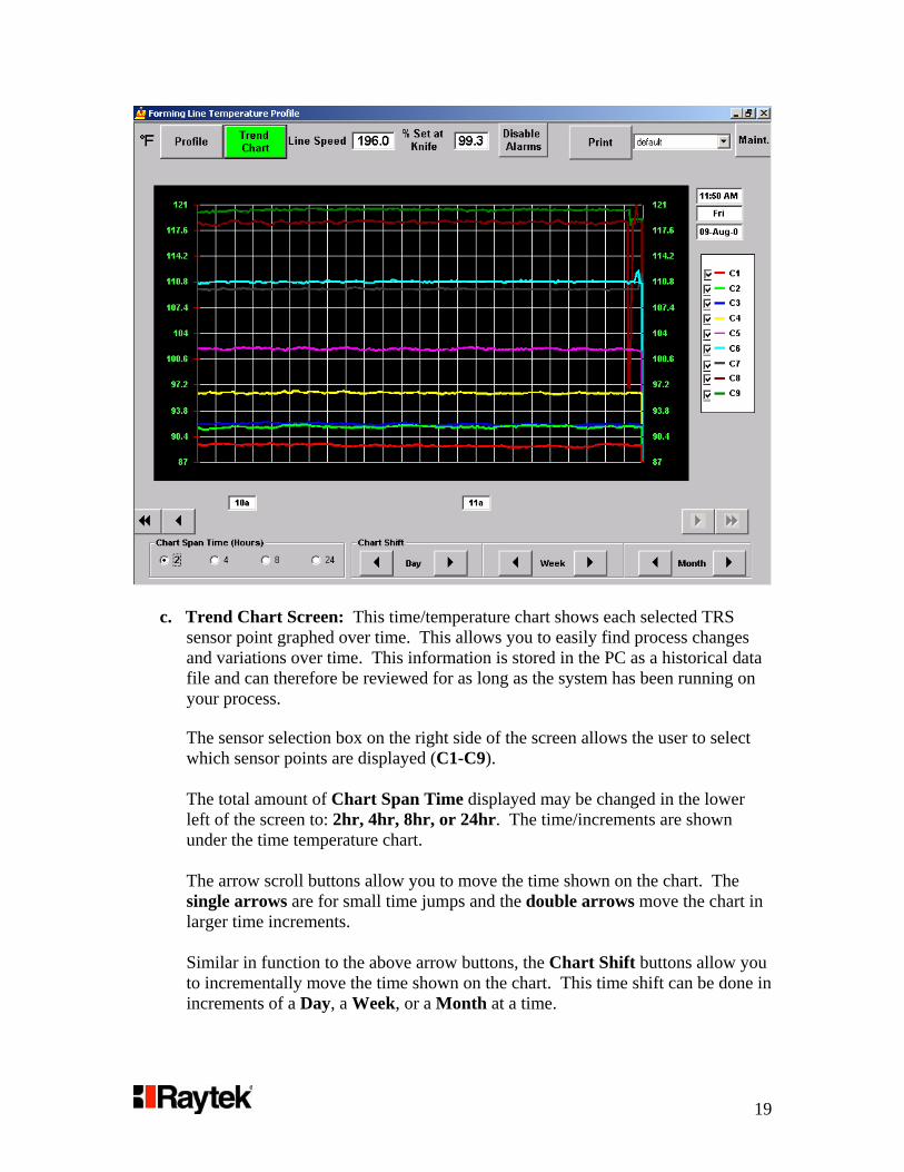
c. Trend Chart Screen: This time/temperature chart shows each selected TRS sensor point graphed over time. This allows you to easily find process changes and variations over time. This information is stored in the PC as a historical data file and can therefore be reviewed for as long as the system has been running on your process.
The sensor selection box on the right side of the screen allows the user to select which sensor points are displayed (C1-C9).
The total amount of Chart Span Time displayed may be changed in the lower left of the screen to: 2hr, 4hr, 8hr, or 24hr. The time/increments are shown under the time temperature chart. The arrow scroll buttons allow you to move the time shown on the chart. The single arrows are for small time jumps and the double arrows move the chart in larger time increments. Similar in function to the above arrow buttons, the Chart Shift buttons allow you to incrementally move the time shown on the chart. This time shift can be done in increments of a Day, a Week, or a Month at a time.
20
The Reset to Real Time button will be displayed anytime the chart is showing historical data. This button allows you to easily get back to the current trend chart.
X. Maintenance
1. Sensor Replacement: If you need to replace a sensor, you will first need to set the appropriate electronic address. The factory default for the sensor address will be “0”. Your other sensors are already addressed as: 1= 1, 2=2,…and 9=9.
WARNING: It is critical that the system power be turned off when removing or connecting any sensor wires. IMPORTANT: When in the Multidrop software Wizard, the Scan must be set to Single Sensor. a. Install Sensor, Scan for Devices and Establish Communications:
1. Install and wire-up the new sensor box with power off
2. Power up the TRS100 system and start the DataTemp Multidrop
Software (Start>Programs>Raytek>DataTemp Multidrop)
3. If the Starter Box with the options to ‘Create or Open a Configuration’ appears, close it by clicking on the X in the upper right hand of the Starter Box
4. The Startup Wizard will start, select COM1 port and the ASCII
protocol. Then click continue
5. Select 9600 Baud and ‘SINGLE’ Sensor from the pulldown menus if not already selected. Select ‘Scan Now for Devices’ button. Click continue
6. The small Communications Progress Box will appear and will
stop scanning after a single sensor has been detected. Since the replacement sensor has a default address of 0, it should be detected first
7. Do not select ‘Launch System Setup’ now, select Finish
b. The second section of the Multidrop software will now display the
temperature of the sensor and allow access to internal sensor settings.
1. Access sensor settings by selecting: SETUP >SETUP SENSOR >SENSOR1

21
2. Select the Advanced SetupTab
3. Click on Polling Number and select the proper Sensor number
(TRS100 Sensor 1 = address 1, 2 = address 2,…9 = address 9)
4. Select the Output Signals tab
5. Select Temperature Unit (F or C). You should be seeing the correct temperature reading.
6. Shut down the Multidrop software and restart the TRS100
software.
2. Sensor Lens Cleaning: Approximately every 60 days, your sensor lenses should be cleaned by using a CLEAN air purge method. The sensor lenses are located inside the black sight tube on each sensor box and at the end of the Sensor 9 dryer infeed assembly. We recommend using a can of clean compressed air – commonly found at computer or office supply stores. If using factory air, ensure there is no oil or particulates.