TROUBLESHOOTING AND SERVICE … TROUBLESHOOTING AND SERVICE INFORMATION FOR VOLTMASTER GENERATORS...
15
1 TROUBLESHOOTING AND SERVICE INFORMATION FOR VOLTMASTER GENERATORS All troubleshooting and service information is offered for the use of authorized Voltmaster service stations. Repairing Generators is not a "Do it Yourself" task. Exposed electrical wires and rotating parts present a danger for personal injury or death. Always wear safety glasses when servicing the generator and or battery. Only qualified electricians and/or authorized service stations are authorized to service these units.
Transcript of TROUBLESHOOTING AND SERVICE … TROUBLESHOOTING AND SERVICE INFORMATION FOR VOLTMASTER GENERATORS...

1
TROUBLESHOOTING AND SERVICE INFORMATION FOR VOLTMASTER GENERATORS
All troubleshooting and service information is offered for the use of authorized Voltmaster servicestations. Repairing Generators is not a "Do it Yourself" task. Exposed electrical wires androtating parts present a danger for personal injury or death. Always wear safety glasses whenservicing the generator and or battery. Only qualified electricians and/or authorized servicestations are authorized to service these units.

2
SUGGESTED REPAIR PROCEDURES FORA,LA,LV,LR, AB, AR, AE, G,V AND VX SERIES
GENERATORS1. Check engine speed (3690 RPM no load) and frequency 61.5 hertz no load. Important onmodels A25/40, 3720 RPM and 62 hertz no load.
2. Open end cover with receptacles exposed. See figure 1. Check lead wires 1,2,3 & 4according to the resistance chart as follows:
Lead wires 1 (black) to lead 2 (white)Lead wires 3 (white) to lead 4 (black)Orange to orange (exciter) Disconnect the red wires to the capacitor before checkingthe resistance in the wires.
Important On some models, lead wire 2(white) and 3 (white) are connected together. See figure2. To test the stator lead wires and leads 1,2,3 and 4 must not be connected together. See figure3.When checking lead wires, leads 2 and 3 are connected together (except A25/30) at thefactory. You must disconnect these leads when testing resistance of the various coils or you willget incorrect readings.
In addition to checking each coil, test each coil to the ground terminal on the aluminum endbracket to see if any winding has gone to ground. If any lead wire indicates positive continuity tothe ground, replace the stator.
3. Check the capacitor for the proper micro farand reading with a capacitor tester. If a capacitortester is not available, use an ohmmeter set at 10k and touch both terminals at the same time.See figure 4. The meter should bounce up with a reading and immediately drop off. If the meterdoes not indicate anything or remains holding a reading, the capacitor is defective and must bereplaced.
Figure 1 Figure 2
Figure 3 Figure 4

3
4. For a unit that has been out of service for a period of time, flashing the field is recommended.See attached instructions.
5. If the first four steps show no failures, remove the stator from the generators. With the statorremoved, the diodes must be checked. To test each diode without disconnecting it from thecircuit, use a 12-volt battery and a 45-watt light bulb (automotive type) as shown in illustration950204. The light should turn on in one direction, as shown. If you cannot test the diodes aspreviously indicated, you must disconnect the copper wires from one end of the diode. You mustalso disconnect the varister (surge suppressor) from the diode. With the wire removed use anohmmeter set to 10K and touch both terminals of the diode. Diodes pass current in one directiononly. If you do not get a reading, reverse the terminals of the meter. If you do not get anyreadings or if you get readings in both directions, the diode is defective. Be sure to check bothdiodes. If you have only one defective diode, it is strongly recommended to replace both diodes.If the positions of the diodes are reversed, you will block the current flow and get no output formthe generator. Pay careful attention to the marking to the current direction of each diode.
6. To check the winding on the rotor you must remove one end the diodes and varister. With anohmmeter check the readings for each coil. The rotor coils are identical. See chart for thevarious ohm readings. Prior to testing resistance in each coil, be sure to zero out your ohmmeter. All readings must be within 20% or less of the published ohms and be consistent (either atslightly higher or slightly lower, not some higher and some lower).

4Out of Use for a Long Period
If the generator set has not been used in over 6 months and the generator worked properly whenlast used, it is very likely that the capacitor is discharged. The capacitor needs to be "flashed" orreenergized.
On A, AB, LA, G, and V units, open the end cover where the receptacles are located. See picture#1. The capacitor is connected to the aluminum casting and has 2 red or orange wires from thegenerator exciter windings. Partially slide the 2 wires back exposing the metal contacts on thecapacitor. Caution! Exposed generator wires present a danger and great care must be taken tonot touch any exposed wires of the generator or electrical shock may occur. Be certain theground surface is dry. Start the engine with no load and apply 12 volts DC from a car battery toboth terminals. There is no polarity issue so it does not matter which terminals you touch.Danger-once you touch the capacitor terminals voltage will start and you have live wires exposed.There will be a small arcing when you touch the capacitor and you will hear a grunt sound fromthe generator. Stop the engine. Carefully slide the 2 wires completely back on the capacitor.Replace the end cover on the generator. Be sure the wires are away from the ball bearing androtor screw in the center of the casting and retighten the screw. Start the engine again and checkthe voltage from each receptacle for proper voltage (120/240 volts for 60 Hz and 110/220 for 50Hz). Note- If, the generator does not produce voltage a day or two after flashing the capacitor,you must replace the capacitor.
LR and LV ModelsThese units have the capacitor on the side of the generator. See figure #2.
5
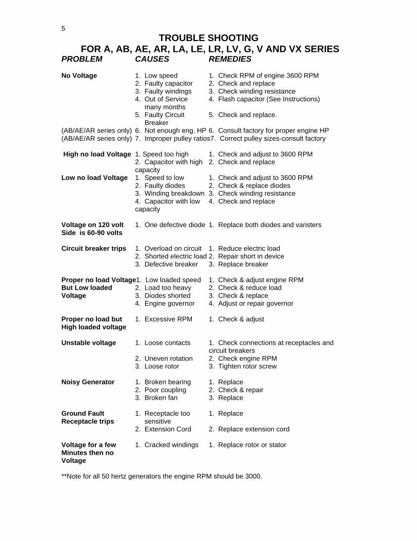
TROUBLE SHOOTING FOR A, AB, AE, AR, LA, LE, LR, LV, G, V AND VX SERIES
PROBLEM CAUSES REMEDIES
No Voltage 1. Low speed 1. Check RPM of engine 3600 RPM2. Faulty capacitor 2. Check and replace3. Faulty windings 3. Check winding resistance4. Out of Service 4. Flash capacitor (See Instructions) many months5. Faulty Circuit 5. Check and replace. Breaker
(AB/AE/AR series only) 6. Not enough eng. HP 6. Consult factory for proper engine HP(AB/AE/AR series only) 7. Improper pulley ratios7. Correct pulley sizes-consult factory
High no load Voltage 1. Speed too high 1. Check and adjust to 3600 RPM2. Capacitor with high 2. Check and replacecapacity
Low no load Voltage 1. Speed to low 1. Check and adjust to 3600 RPM2. Faulty diodes 2. Check & replace diodes3. Winding breakdown 3. Check winding resistance4. Capacitor with low 4. Check and replacecapacity
Voltage on 120 volt 1. One defective diode 1. Replace both diodes and varistersSide is 60-90 volts
Circuit breaker trips 1. Overload on circuit 1. Reduce electric load2. Shorted electric load 2. Repair short in device3. Defective breaker 3. Replace breaker
Proper no load Voltage1. Low loaded speed 1. Check & adjust engine RPMBut Low loaded 2. Load too heavy 2. Check & reduce loadVoltage 3. Diodes shorted 3. Check & replace
4. Engine governor 4. Adjust or repair governor
Proper no load but 1. Excessive RPM 1. Check & adjustHigh loaded voltage
Unstable voltage 1. Loose contacts 1. Check connections at receptacles andcircuit breakers
2. Uneven rotation 2. Check engine RPM3. Loose rotor 3. Tighten rotor screw
Noisy Generator 1. Broken bearing 1. Replace2. Poor coupling 2. Check & repair3. Broken fan 3. Replace
Ground Fault 1. Receptacle too 1. ReplaceReceptacle trips sensitive
2. Extension Cord 2. Replace extension cord
Voltage for a few 1. Cracked windings 1. Replace rotor or statorMinutes then noVoltage
**Note for all 50 hertz generators the engine RPM should be 3000.
6
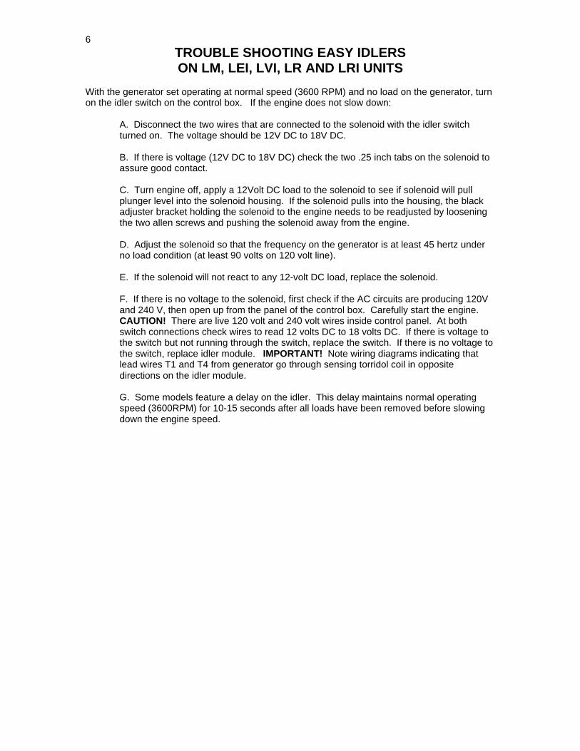
TROUBLE SHOOTING EASY IDLERSON LM, LEI, LVI, LR AND LRI UNITS
With the generator set operating at normal speed (3600 RPM) and no load on the generator, turnon the idler switch on the control box. If the engine does not slow down:
A. Disconnect the two wires that are connected to the solenoid with the idler switchturned on. The voltage should be 12V DC to 18V DC.
B. If there is voltage (12V DC to 18V DC) check the two .25 inch tabs on the solenoid toassure good contact.
C. Turn engine off, apply a 12Volt DC load to the solenoid to see if solenoid will pullplunger level into the solenoid housing. If the solenoid pulls into the housing, the blackadjuster bracket holding the solenoid to the engine needs to be readjusted by looseningthe two allen screws and pushing the solenoid away from the engine.
D. Adjust the solenoid so that the frequency on the generator is at least 45 hertz underno load condition (at least 90 volts on 120 volt line).
E. If the solenoid will not react to any 12-volt DC load, replace the solenoid.
F. If there is no voltage to the solenoid, first check if the AC circuits are producing 120Vand 240 V, then open up from the panel of the control box. Carefully start the engine.CAUTION! There are live 120 volt and 240 volt wires inside control panel. At bothswitch connections check wires to read 12 volts DC to 18 volts DC. If there is voltage tothe switch but not running through the switch, replace the switch. If there is no voltage tothe switch, replace idler module. IMPORTANT! Note wiring diagrams indicating thatlead wires T1 and T4 from generator go through sensing torridol coil in oppositedirections on the idler module.
G. Some models feature a delay on the idler. This delay maintains normal operatingspeed (3600RPM) for 10-15 seconds after all loads have been removed before slowingdown the engine speed.

7
TROUBLE SHOOTING THE LV150With automatic voltage regulators
PROBLEM CAUSE REMEDIES
Alternator does not 1. Interrupted fuse 1. Replace fuseExcite 2. Insufficient residual voltage 2. Increase speed by 15%
3. No residual voltage 3. For an instant apply on the + and –terminals of the electronic regulator a12-volt battery voltage with a 30Wresistor in series respecting thepolarities
4. Bad capacitor 4. Replace capacitor
After being excited 1. Connections are interrupted 1. Check connection cables as perAlternator does not attached drawingsExcite
Low voltage at no load1. Voltage potentiometer out 1. Reset voltageof setting2. Intervention of protection 2. Check RPM3. Winding failure. 3. Check windings
High Voltage at 1. Voltage potentiometer out 1. Reset voltageNo load of setting
2. Failed regulator 2. Replace regulator3. Engine RPM too high 3. Adjust RPM
Lower than rated 1. Voltage potentiometer out 1. Reset voltage potentiometer.Voltage at load of setting
2. Intervention by protection 2. Current too high, power factor lowerthan 0.8; speed lower than 4% of ratedspeed
3. Failed regulator. 3. Replace regulator4. Rotating bridge failure 4. Check diodes, disconnect cables.5. Engine RPM too low 5. Adjust RPM
Higher than rated 1. Voltage potentiometer out 1. Reset voltage potentiometerVoltage at load of setting
2. Failed regulator 2. Replace regulator3. Capacitor value too high 3. Replace capacitor
Unstable voltage 1. Speed variation in engine 1. Check uniformity of rotation2. Regulator out of setting 2. Regulate stability of regulator
by acting on "STABILITY"potentiometer with light bulb pluggedinto 120 volt receptacle
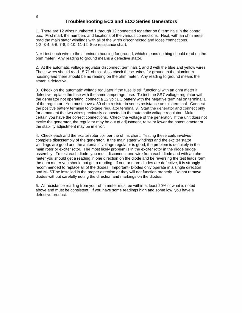
8Troubleshooting EC3 and ECO Series Generators
1. There are 12 wires numbered 1 through 12 connected together on 6 terminals in the controlbox. First mark the numbers and locations of the various connections. Next, with an ohm meterread the main stator windings with all of the wires disconnected and loose connections.1-2, 3-4, 5-6, 7-8, 9-10, 11-12 See resistance chart.
Next test each wire to the aluminum housing for ground, which means nothing should read on theohm meter. Any reading to ground means a defective stator.
2. At the automatic voltage regulator disconnect terminals 1 and 3 with the blue and yellow wires.These wires should read 15.71 ohms. Also check these wires for ground to the aluminumhousing and there should be no reading on the ohm meter. Any reading to ground means thestator is defective.
3. Check on the automatic voltage regulator if the fuse is still functional with an ohm meter ifdefective replace the fuse with the same amperage fuse. To test the SR7 voltage regulator withthe generator not operating, connect a 12 volt DC battery with the negative terminal on terminal 1of the regulator. You must have a 30 ohm resister in series resistance on this terminal. Connectthe positive battery terminal to voltage regulator terminal 3. Start the generator and connect onlyfor a moment the two wires previously connected to the automatic voltage regulator. Makecertain you have the correct connections. Check the voltage of the generator. If the unit does notexcite the generator, the regulator may be out of adjustment, raise or lower the potentiometer orthe stability adjustment may be in error.
4. Check each and the exciter rotor coil per the ohms chart. Testing these coils involvescomplete disassembly of the generator. If the main stator windings and the exciter statorwindings are good and the automatic voltage regulator is good, the problem is definitely in themain rotor or exciter rotor. The most likely problem is in the exciter rotor in the diode bridgeassembly. To test each diode, you must disconnect one wire from each diode and with an ohmmeter you should get a reading in one direction on the diode and be reversing the test leads formthe ohm meter you should not get a reading. If one or more diodes are defective, it is stronglyrecommended to replace all of the diodes. Important- Diodes only operate in a single directionand MUST be installed in the proper direction or they will not function properly. Do not removediodes without carefully noting the direction and markings on the diodes.
5. All resistance reading from your ohm meter must be within at least 20% of what is notedabove and must be consistent. If you have some readings high and some low, you have adefective product.
9
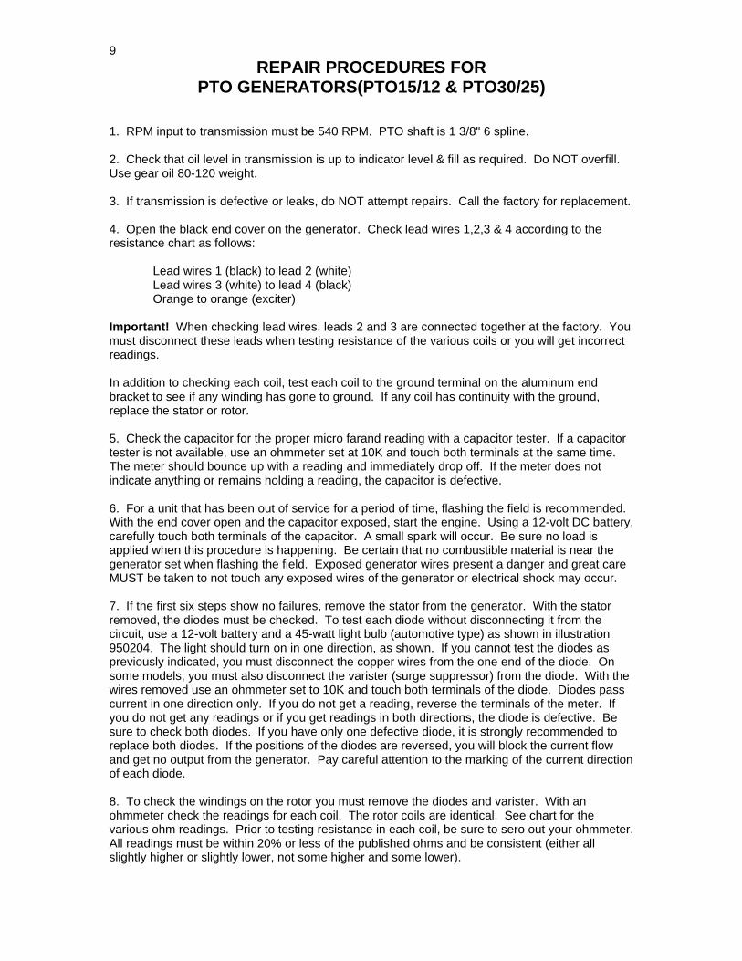
REPAIR PROCEDURES FORPTO GENERATORS(PTO15/12 & PTO30/25)
1. RPM input to transmission must be 540 RPM. PTO shaft is 1 3/8" 6 spline.
2. Check that oil level in transmission is up to indicator level & fill as required. Do NOT overfill.Use gear oil 80-120 weight.
3. If transmission is defective or leaks, do NOT attempt repairs. Call the factory for replacement.
4. Open the black end cover on the generator. Check lead wires 1,2,3 & 4 according to theresistance chart as follows:
Lead wires 1 (black) to lead 2 (white)Lead wires 3 (white) to lead 4 (black)Orange to orange (exciter)
Important! When checking lead wires, leads 2 and 3 are connected together at the factory. Youmust disconnect these leads when testing resistance of the various coils or you will get incorrectreadings.
In addition to checking each coil, test each coil to the ground terminal on the aluminum endbracket to see if any winding has gone to ground. If any coil has continuity with the ground,replace the stator or rotor.
5. Check the capacitor for the proper micro farand reading with a capacitor tester. If a capacitortester is not available, use an ohmmeter set at 10K and touch both terminals at the same time.The meter should bounce up with a reading and immediately drop off. If the meter does notindicate anything or remains holding a reading, the capacitor is defective.
6. For a unit that has been out of service for a period of time, flashing the field is recommended.With the end cover open and the capacitor exposed, start the engine. Using a 12-volt DC battery,carefully touch both terminals of the capacitor. A small spark will occur. Be sure no load isapplied when this procedure is happening. Be certain that no combustible material is near thegenerator set when flashing the field. Exposed generator wires present a danger and great careMUST be taken to not touch any exposed wires of the generator or electrical shock may occur.
7. If the first six steps show no failures, remove the stator from the generator. With the statorremoved, the diodes must be checked. To test each diode without disconnecting it from thecircuit, use a 12-volt battery and a 45-watt light bulb (automotive type) as shown in illustration950204. The light should turn on in one direction, as shown. If you cannot test the diodes aspreviously indicated, you must disconnect the copper wires from the one end of the diode. Onsome models, you must also disconnect the varister (surge suppressor) from the diode. With thewires removed use an ohmmeter set to 10K and touch both terminals of the diode. Diodes passcurrent in one direction only. If you do not get a reading, reverse the terminals of the meter. Ifyou do not get any readings or if you get readings in both directions, the diode is defective. Besure to check both diodes. If you have only one defective diode, it is strongly recommended toreplace both diodes. If the positions of the diodes are reversed, you will block the current flowand get no output from the generator. Pay careful attention to the marking of the current directionof each diode.
8. To check the windings on the rotor you must remove the diodes and varister. With anohmmeter check the readings for each coil. The rotor coils are identical. See chart for thevarious ohm readings. Prior to testing resistance in each coil, be sure to sero out your ohmmeter.All readings must be within 20% or less of the published ohms and be consistent (either allslightly higher or slightly lower, not some higher and some lower).
10
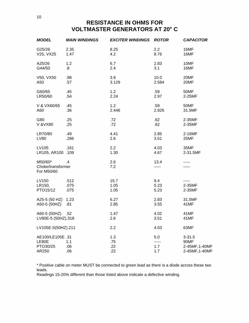
RESISTANCE IN OHMS FORVOLTMASTER GENERATORS AT 20° C
MODEL MAIN WINDINGS EXCITER WINDINGS ROTOR CAPACITOR
G25/26 2.35 8.25 2.2 16MFV25, VX25 1.47 4.2 8.76 16MF
A25/26 1.2 6.7 2.83 10MFG44/50 .8 2.4 3.1 16MF
V50, VX50 .98 3.9 10.0 20MFA50 .57 3.129 2.584 20MF
G60/65 .45 1.2 .59 50MFLR50/60 .54 2.24 2.97 2-25MF
V & VX60/65 .45 1.2 .59 50MFA60 .36 2.446 2.926 31.5MF
G80 .25 .72 .62 2-35MFV &VX80 .25 .72 .62 2-35MF
LR70/80 .49 4.41 2.85 2-16MFLV80 .286 2.6 3.51 25MF
LV105 .161 2.2 4.03 35MFLR105, AR100 .109 1.30 4.67 2-31.5MF
M50/60* .4 2.6 13.4 -----Choke/transformer 7.2 ----- -----For M50/60
LV150 .512 15.7 9.4 -----LR150, .075 1.05 5.23 2-35MFPTO15/12 .075 1.05 5.23 2-35MF
A25-5 (50 HZ) 1.23 6.27 2.83 31.5MFA50-5 (50HZ) .81 2.85 3.55 41MF
A60-5 (50HZ) .52 1.47 4.02 41MFLV80E-5 (50HZ).318 2.6 3.51 41MF
LV105E-5(50HZ).211 2.2 4.03 63MF
AE100/LE105E .31 1.3 5.0 3-31.5LE80E 1.1 .75 ----- 90MFPTO30/25 .06 .22 1.7 2-45MF,1-40MFAR250 .06 .22 1.7 2-45MF,1-40MF
* Positive cable on meter MUST be connected to green lead as there is a diode across these twoleads.Readings 15-20% different than those listed above indicate a defective winding.

11
RESISTANCE IN OHMS FORVOLTMASTER 4-POLE GENERATORS AT 20°C
ModelMainStator
MainRotor
Aux. Winding Stator
ExciterRotor
EC8-3,EC7-1 1.084 7.3252.02 15.71 1.453
EC13-3.EC11-1 0.443 9.811.542 15.71 1.453
EC15-3,EC12.5-1 0.283 1.264.06 10.6 0.39
EC29-3, EC24-1 0.1 1.862.17 10.6 0.39
EC40-3, EC30-1PT040-1,PT055-3 0.078 2.1630.929 10.6 0.39
EC50-3, EC40-1PT050·1, PT055-3 0.061 2.4730.993 11.35 0.47
EC65-3, EC50-1PT065-1,PT070-3 0.035 3.1710.79 11.35 0.47
EC80-3, EC67-1PT075-1,PT090-3 0.03 2.4770.965 15.28 0.41
EC100-3,EC83-1 0.02 2.9510.838 15.28 0.41
EC120-3,EC100-1PT0110-3 0.018 3.1650.796 15.28 0.41
EC145-3,EC120-1 0.015 3.5770.914 15.28 0.41
EC176-3,EC145-1 0.0131 3.960.79 15.28 0.41
EC215-3,EC180-1 0.009 5.0350.635 15.28 0.41
EC240-3, EC200-1 0.0075 5.5250.633 15.28 0.41
EC325-3, EC270-1 0.0042 7.0950.622 15.28 0.41
AVR
SR7
SR7
SR7
SR7
ModelMainStator
RotorWinding
Exciter Winding
CompoundAuxiliary
CompoundExciter
LR50-208, LR80-208 0.14 9.180.445 21.3 0.67LR50-480, LR80-480 0.712 9.180.445 109 0.67
ImpedanceGenerator
ImpedanceAuxiliary
W180, W240 0.3 9.180.022 0.03 0.83
LR120-208 0.11 11.490.474 19.5 0.67LR120-480 0.425 11.490.474 112.8 0.67
SR7
SR7
SR7
SR7
SR7
SR7
SR7
UVR
UVR
UVR
UVR
RESISTANCE IN OHMS FOR VOLTMASTER 3-PHASE GENERATORS AND WELDERS AT 20°C
Models produced in 2006 and later
Models produced in 2006 and later
12
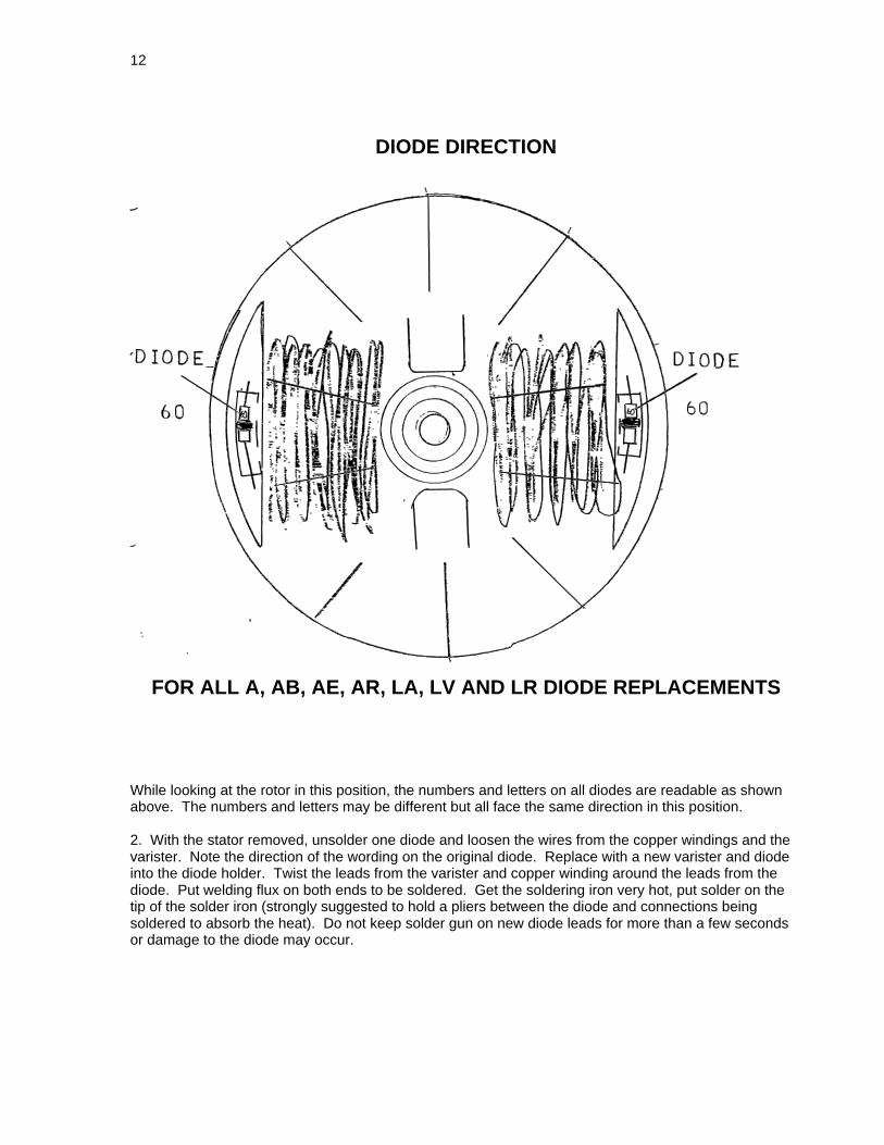
DIODE DIRECTION
FOR ALL A, AB, AE, AR, LA, LV AND LR DIODE REPLACEMENTS
While looking at the rotor in this position, the numbers and letters on all diodes are readable as shownabove. The numbers and letters may be different but all face the same direction in this position.
2. With the stator removed, unsolder one diode and loosen the wires from the copper windings and thevarister. Note the direction of the wording on the original diode. Replace with a new varister and diodeinto the diode holder. Twist the leads from the varister and copper winding around the leads from thediode. Put welding flux on both ends to be soldered. Get the soldering iron very hot, put solder on thetip of the solder iron (strongly suggested to hold a pliers between the diode and connections beingsoldered to absorb the heat). Do not keep solder gun on new diode leads for more than a few secondsor damage to the diode may occur.
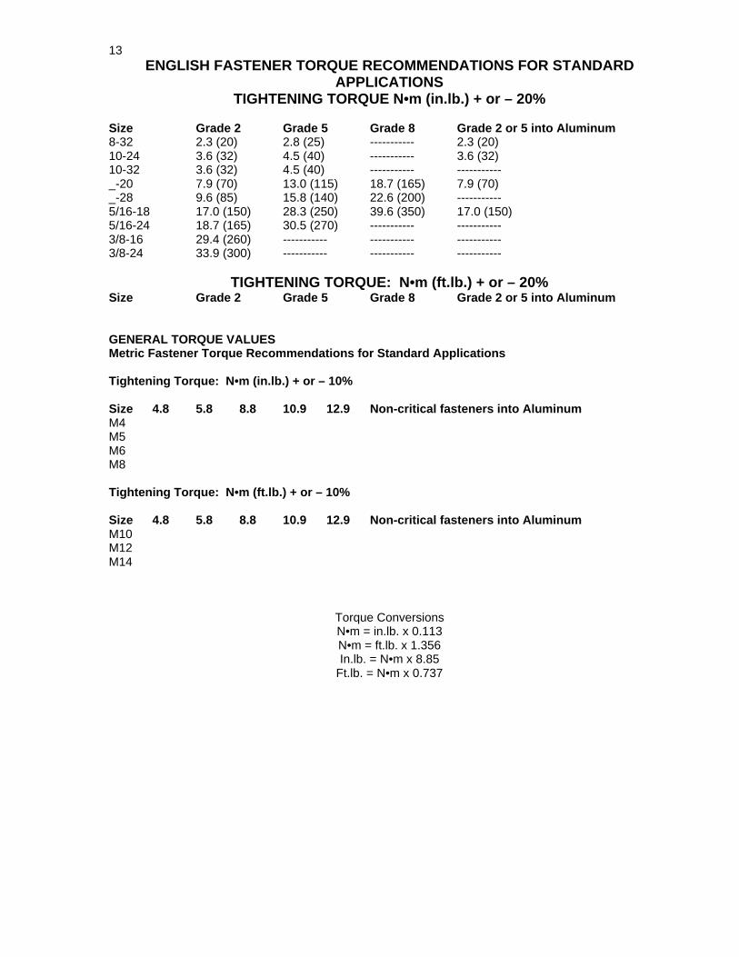
13ENGLISH FASTENER TORQUE RECOMMENDATIONS FOR STANDARD
APPLICATIONSTIGHTENING TORQUE N•m (in.lb.) + or – 20%
Size Grade 2 Grade 5 Grade 8 Grade 2 or 5 into Aluminum8-32 2.3 (20) 2.8 (25) ----------- 2.3 (20)10-24 3.6 (32) 4.5 (40) ----------- 3.6 (32)10-32 3.6 (32) 4.5 (40) ----------- -----------_-20 7.9 (70) 13.0 (115) 18.7 (165) 7.9 (70)_-28 9.6 (85) 15.8 (140) 22.6 (200) -----------5/16-18 17.0 (150) 28.3 (250) 39.6 (350) 17.0 (150)5/16-24 18.7 (165) 30.5 (270) ----------- -----------3/8-16 29.4 (260) ----------- ----------- -----------3/8-24 33.9 (300) ----------- ----------- -----------
TIGHTENING TORQUE: N•m (ft.lb.) + or – 20%Size Grade 2 Grade 5 Grade 8 Grade 2 or 5 into Aluminum
GENERAL TORQUE VALUESMetric Fastener Torque Recommendations for Standard Applications
Tightening Torque: N•m (in.lb.) + or – 10%
Size 4.8 5.8 8.8 10.9 12.9 Non-critical fasteners into AluminumM4M5M6M8
Tightening Torque: N•m (ft.lb.) + or – 10%
Size 4.8 5.8 8.8 10.9 12.9 Non-critical fasteners into AluminumM10M12M14
Torque ConversionsN•m = in.lb. x 0.113N•m = ft.lb. x 1.356In.lb. = N•m x 8.85
Ft.lb. = N•m x 0.737
14
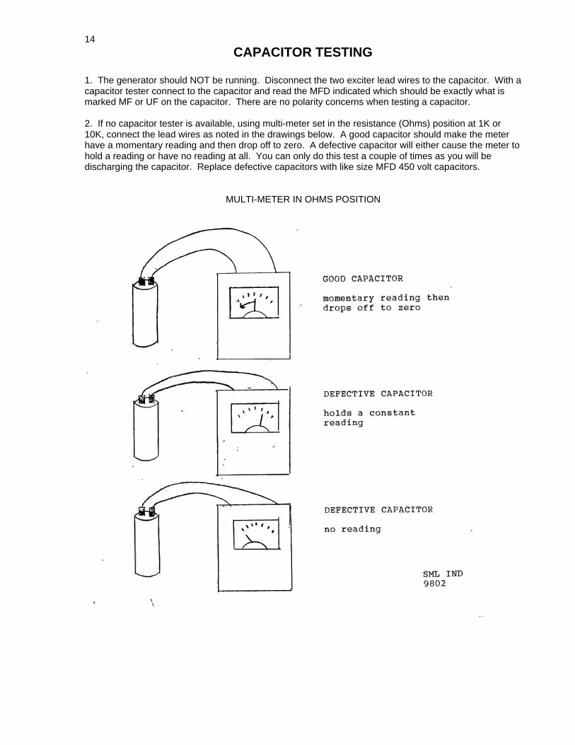
CAPACITOR TESTING
1. The generator should NOT be running. Disconnect the two exciter lead wires to the capacitor. With acapacitor tester connect to the capacitor and read the MFD indicated which should be exactly what ismarked MF or UF on the capacitor. There are no polarity concerns when testing a capacitor.
2. If no capacitor tester is available, using multi-meter set in the resistance (Ohms) position at 1K or10K, connect the lead wires as noted in the drawings below. A good capacitor should make the meterhave a momentary reading and then drop off to zero. A defective capacitor will either cause the meter tohold a reading or have no reading at all. You can only do this test a couple of times as you will bedischarging the capacitor. Replace defective capacitors with like size MFD 450 volt capacitors.
MULTI-METER IN OHMS POSITION

15
FIGURE 950204
DIODE TEST WITHOUT REMOVING THE DIODE FROM THE ROTOR
Connect a 12 volt DC battery and a 45 watt (automobile type) bulb as shown below. The light will turn onin one direction only as shown.