TRIM TRIO and SEALOK -...
130
TRIM TRIO and SEALOK interconnection system
Transcript of TRIM TRIO and SEALOK -...

TRIM TRIOand SEALOKinterconnectionsystem

Introduction
TRIM TRIO and SEALOK products are produced by the Interconnections division of FCI.The products are marketed through the International sales organisations of FCI as indicated on the backpage of this catalogue.
Connectors for Industrial markets
FCI Technology and CapabilityAlways attentive to the diversified needs of industrial equipment manufacturers, FC-Belgium has developed an unparalleled range of competitive options for signal andpower applications addressing electronic controls, scientific and medicalinstrumentation, servo drives and motors for machine tools and robots.
In house capabilities such as research and development, product and tool design,moulding, stamping, plating and assembly, created a substantial knowledge base inmaterial research of advanced plastics and moulding, as well as metal forming andplating techniques, that improve the performance capabilities of our connectorproducts.
State-of-the art computer techniques have improved the precision of our connectordesigns and have reduced the overall cycle for new product developments anddesign-in projects.
FCI Commitment to QualityFCI connectors for the Industrial markets are all produced with modern qualityassurance methods to obtain the product reliability required by our customers.This commitment to quality has pursued ISO 9001 certification, ensuring that manyaspects of our business are being continuously upgraded and refined to guaranteethe continuation of our quality improvement achievements.
FCI was created in 1989. Thecompany is now the second largestconnector manufacturer in the worldand is the only European Companyamongst the first 10 worldwide.Its activities are geared towards fivemajor sectors: electronics, industrial,military and aerospace, electricalequipment, microelectronics andautomotive.FCI has its headquarters in Paris andemploys more than 17,000 people inthe world.With more than 60 production plantsin 28 countries, FCI accounts forapproximately 50% of the total sales ofthe Framatome Group, of which theFCI company is a subsidiary.
FCI connects the world

OverviewG - Bantamate UTG - Metalok Bantam UTP - Full plastic Bantam
DescriptionMetal circular connector with metal bayonetcoupling system
RangeShell sizes: 8Contact arrangements: 8 (4 to 48)
FeaturesDerived from MIL - C 26482Intermateable with UTG / UTP and UTGSIP65 (waterprotected version) - 5 sizesSuitable for EMC requirementsMin 500 matings/unmatings
AccessoriesDifferent types of cable clamps Shielded cable clampDustcapsDiscrimination pins
DescriptionPlastic circular connector with metal bayonetcoupling system
RangeShell sizes: 8Contact arrangements: 11 (3 to 48)
FeaturesDerived from MIL - C 26482Intermateable with UTO / UTP IP65 (waterprotected version)Min 500 matings/unmatings3 VDE versions, 2 power versions
AccessoriesDifferent types of cable clamps DustcapsDiscrimination pins
DescriptionFull plastic circular connector with ruggedplastic bayonet coupling system
RangeShell sizes: 8Contact arrangements: 10 (3 to 48)
FeaturesDerived from MIL - C 26482Intermateable with UTO / UTGIP65 (waterprotected version)Min 250 matings/unmatings2 VDE versions
AccessoriesDifferent type of cable clamps DustcapsDiscrimination pins
UTGS - Shielded Bantam UTGW - SEALOK MBG - Banatamate II
DescriptionMetallised plastic circular connector withmetal bayonet coupling system for EMCrequirements
RangeShell sizes: 8Contact arrangements: 11 (3 to 48)
FeaturesDerived from MIL - C 26482Intermateable with UTOIP65 (waterprotected version)Suitable for EMC requirementsMin 500 matings/unmatings3 VDE versions
AccessoriesDustcapsDiscrimination pins
DescriptionPlastic circular high density connector withmetal bayonet coupling system, intermateablewith MIL - C - 26482 Series I connectors
RangeShell sizes: 7Contact arrangements: 7 (6 to 61)
FeaturesIntermateable and intermountable withMIL - C 26482 Series I connectorsIP65 (waterprotected version)Min 500 matings/unmatingsMilitary performance levels
AccessoriesDifferent types of cable clamps Dustcaps
DescriptionPlastic circular connector with metal quickmating feature
RangeShell sizes: 5Contact arrangements: 5 (4 to 46)
FeaturesMin 5000 matings/unmatingsQuick and easy mating with latching system
AccessoriesCable clamp
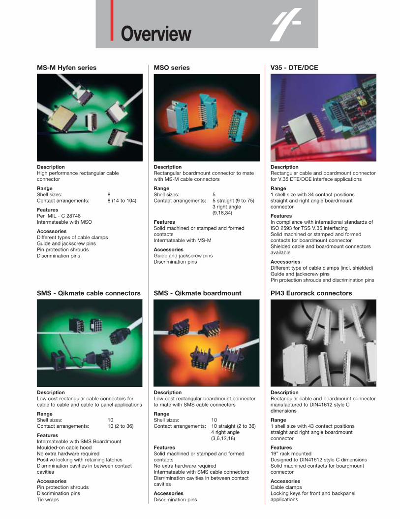
OverviewMS-M Hyfen series MSO series V35 - DTE/DCE
DescriptionHigh performance rectangular cableconnector
RangeShell sizes: 8Contact arrangements: 8 (14 to 104)
FeaturesPer MIL - C 28748 Intermateable with MSO
AccessoriesDifferent types of cable clamps Guide and jackscrew pinsPin protection shroudsDiscrimination pins
DescriptionRectangular boardmount connector to matewith MS-M cable connectors
RangeShell sizes: 5Contact arrangements: 5 straight (9 to 75)
3 right angle(9,18,34)
FeaturesSolid machined or stamped and formedcontactsIntermateable with MS-M
AccessoriesGuide and jackscrew pinsDiscrimination pins
DescriptionRectangular cable and boardmount connectorfor V.35 DTE/DCE interface applications
Range1 shell size with 34 contact positionsstraight and right angle boardmountconnector
FeaturesIn compliance with international standards ofISO 2593 for TSS V.35 interfacingSolid machined or stamped and formedcontacts for boardmount connectorShielded cable and boardmount connectorsavailable
AccessoriesDifferent type of cable clamps (incl. shielded) Guide and jackscrew pinsPin protection shrouds and discrimination pins
SMS - Qikmate cable connectors SMS - Qikmate boardmount PI43 Eurorack connectors
DescriptionLow cost rectangular cable connectors forcable to cable and cable to panel applications
RangeShell sizes: 10Contact arrangements: 10 (2 to 36)
FeaturesIntermateable with SMS BoardmountMoulded-on cable hoodNo extra hardware requiredPositive locking with retaining latchesDisrrimination cavities in between contactcavities
AccessoriesPin protection shroudsDiscrimination pinsTie wraps
DescriptionLow cost rectangular boardmount connectorto mate with SMS cable connectors
RangeShell sizes: 10Contact arrangements: 10 straight (2 to 36)
4 right angle(3,6,12,18)
FeaturesSolid machined or stamped and formedcontactsNo extra hardware requiredIntermateable with SMS cable connectorsDisrrimination cavities in between contactcavities
AccessoriesDiscrimination pins
DescriptionRectangular cable and boardmount connectormanufactured to DIN41612 style Cdimensions
Range1 shell size with 43 contact positionsstraight and right angle boardmountconnector
Features19” rack mountedDesigned to DIN41612 style C dimensionsSolid machined contacts for boardmountconnector
AccessoriesCable clampsLocking keys for front and backpanelapplications

Trim Trio + SealokIn house capabilities
R&DProduct engineeringTool designManufacturing engineering
Toolroom
Moulding
Stamping
Plating
Assembly

3
Index• Circular connectors Page
Circular introduction Circular introduction 1
Metal circular connector G – Bantamate 12
Plastic connector with metal coupling system UTG – Metalok Bantam 17
Full plastic circular connector UTP – Full plastic Bantam 21
Shielded connectors... how to assemble ... Shielding, how to assemble... 24
Shielded connectors for EMC requirements UTGS – Shielded Bantam 27
Specials Circular specials 31
Plastic high density connector with metal coupling system UTGW – Sealok 35
Circular accessories Circular accessories 40
Plastic connector with quick mating feature MBG – Bantamate II 48
• Rectangular connectors
Rectangular introduction Rectangular introduction 52
High performance cable connectors MS–M 53
Rectangular boardmount connectors MS0 61
V.35 DTE/DCE interface connectors V.35 DTE/DCE 66
Economical connectors SMS – Qikmate 72
Eurorack connectors PI43 87
• Contacts
Contacts introduction Contacts introduction 99
Machined TRIM TRIO contacts RM/RC 103
Stamped and formed TRIM TRIO contacts SM–M/SC–M 106
Coax TRIM TRIO contacts RMDX/RCDX 108
Stamped and formed SEALOK contacts SM–W/SC–W 114
Fibre optic TRIM TRIO contacts 8012 – Fibre optic 116
• Accessories
Discrimination keys for TRIM TRIO connectors Dicrimination keys 117
• Tooling
Tooling introduction Tooling introduction 119
Crimp and extraction tooling for TRIM TRIO and SEALOK contacts Crimptooling1 120

4
IntroductionTRIM TRIO – The principle
The TRIM TRIO interconnection system is afully integrated system, in which 4 contacttypes can be used in a variety of connectorstyles and sizes, ranging from 1 to 104contact positions.This interchangeability offers boundlessdesign possibilities with a large commonalitythroughout the entire range.
The commonality in the system isestablished in:– contact performance and wire range.– configuration of contact cavities in the
housings.– crimp tooling– assembly procedures.– quality assurance procedures.– field service and maintenance.– personnel training.
ProductsThe contacts, both male and female,accommodate a wire range of AWG14 up toAWG30. The 4 contact families are:– machined contacts for high performance
(up to 13 Amp current rating), with gold ortin plating.
– stamped and formed two–piece contacts,for more cost effective applications (up to13 Amp current rating).
– subminiature coaxial contacts, in amulti–piece and a mono–crimp version, forcoaxial or twisted–pair cables.
– Fibre optic contacts to accommodate1000 µ plastic fibres with a cable diameterof 2.2 mm.
The housings offer many options in contactcavities and backshell possibilities. The main versions are:– circular connectors:– • full metal– • plastic with metal coupling system– • full plastic– • metallised plastic for shielding– • plastic with quick mating feature– rectangular, high performance, rack and
panel and printed circuit board versions.– rectangular, low cost, rack and panel and
printed circuit board versions.– rectangular connectors for V.35
applications.– rectangular connectors for eurorack
applications.
(See TRIM TRIO selection matrix on the nextpage)
The beauty of the TRIM TRIO system meansthat the 4 contact types can be combined(both male and female) in any TRIM TRIOconnector type of any geometry.
The keywords in the TRIM TRIOinterconnection system are standardisation,versatility, reliability and economy.These words explain why the TRIM TRIOname is so well known, and its connectorsare used all over the world.
Standardisation• The same contact cavity for each type of
housing• identical crimp tooling for all types of
contacts except fibre optics
• reduced manufacturing methods• standardised operator training• international acceptance
Versatility• wide range in current capability• various contact platings• wire and cable accommodations• housings accommodate pin and socket
(male and female) contacts• variety of terminations• variations in mounting• number of sizes• discrimination keying• broad range of installation tooling• variety of possible applications
Reliability• proven materials• guaranteed quality assurance per
ISO 9001 certification• rigid inspection procedures• positive polarisation• pin protection• rugged mouldings• restricted entry contacts
Economy• low assembly cost• minimal tooling downtime• easy connecting and disconnecting• low wiring cost• simplified personnel education• low inspection cost• removable contacts• reduced number of components• low installed cost
5
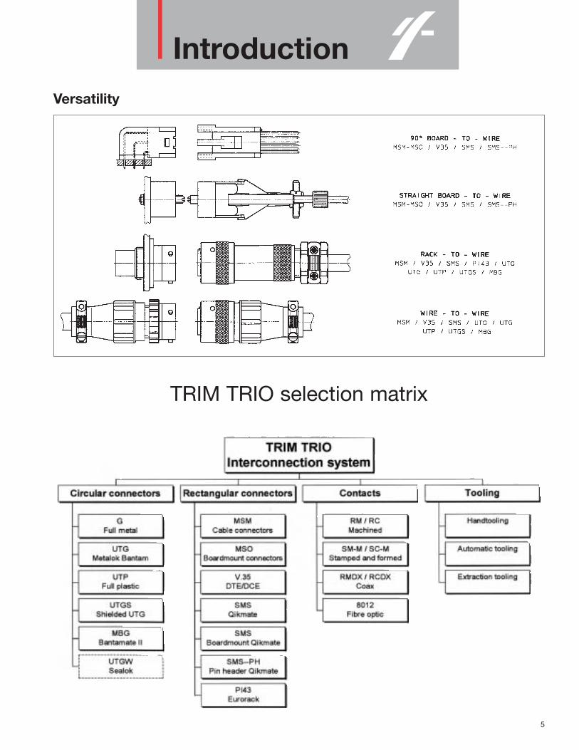
IntroductionVersatility
TRIM TRIO selection matrix

6
CircularDescription
The TRIM TRIO and SEALOK circularconnectors are an integrated group ofeconomical, reliable, versatile standardisedconnectors for a broad spectrum ofinterconnection applications. Being derived from MIL-C-26482, input andoutput connections can be made with alarge number of sizes ranging from:4 to 48 contact positions in TRIM TRIO4 to 46 contact positions in MBG Bantamate II6 to 61 contact positions in SEALOK
What are the links anddifferences between TRIM TRIO circular, MBG Bantamate II and SEALOK ?
To avoid misunderstandings on the circularconnector ranges, it has to be clearlyunderstood that there are inevitable linksand differences between all the circularproduct ranges (see fig).
Intermateability
• TRIM TRIO circular connectors areavailable in G, UTG, UTP and UTGS andare fully intermateable, interchangeableand intermountable.
• MBG Bantamate II with his unique quickmating feature plus high number of matingcycles is not mateable with other TRIMTRIO circular connectors.
• SEALOK is derived from UTG range inTRIM TRIO and is fully intermateable and intermountable with MIL-C-26482(62GB) and VG-95328 connectors.
Contacts
• TRIM TRIO and MBG Bantamate II circularconnectors are using the size 16 TRIMTRIO contacts available in machined,stamped and formed, coax and fibre opticversions.
• SEALOK uses size 20 SEALOK contacts,only available in stamped and formedversions.
Accessories
• TRIM TRIO and Sealok use the sameaccessories such as backshells anddustcaps.
• MBG Bantamate II has his own backshell
Tooling
• TRIM TRIO and MBG Bantamate II andSEALOK use all the same crimp barrelsper wire size and the same crimptooling.

7
Circular
Selection matrix Circular connectors
CIR
CU
LAR
IN
TR
OD
UC
TIO
N

8
CircularTRIM TRIO Insert arrangements and moulded-in contact identificationTRIM TRIO arrangements only available for UTG, UTGS and UTP
TRIM TRIO additional arrangements only available for UTG, UTGS and UTP
Contact identification positions shown are for mating face of pin contact, connectors, and wire face of socket contact connectors.

9
Circular
SEALOK insert arrangements
Trim Trio G Series Insert Arrangements
Marking on wiring face is moulded-in.Marking on mating face is mouded-in for socket versions. For pin versions, each mating face has an interfacial seal with silkscreen marking.
CIR
CU
LAR
IN
TR
OD
UC
TIO
N
*Also available in interfacial seal version. To order, add suffix number 21 to standard catalog number.
10-4 12-88 14-92* 16-19
18-22* 20-30* 22-38* 24-48*

10
CircularMating Dimensions TRIM TRIO and SEALOK
Shellsize
Dimensions in mm
A max. B max. C max. D max. E max. F max. G ±0.2 H max. J max.
10 57 72 57.5 72.5 106 13612 74 74.0 13914 63 81 63.5 81 24.3 11.4 118 15316 85 85 16118 67 88 31.8 67.5 89 126 16820 74 101 76 103 14.6 140 19122 79 117 82 110 26 151 20724 84 123 88 127 15.4 162 240
10-3VDE 57 72 57.5 72.5 31.7 11.4 106 13618-7 VDE 73.5 94,5 33 74 95.5 34 17.9 133 17520-20VDE 74 101 31.8 76 103 26 14.6 140 191

11
CircularTRIM TRIO cavity dimensions on wire face
SEALOK cavity dimensions on wire face
TRIM TRIO and SEALOK threading dimensionsShell size Shell thread size for backshells PG - thread on PG cable clamp
10 9/16 - 24 UNEF PG912 11/16 - 24 UNEF PG1114 13/16 - 20 UNEF PG13.516 15/16 - 20 UNEF PG1618 1-1/16 - 18 UNEF20 1-3/16 - 18 UNEF PG2122 1-5/16 - 18 UNEF24 1-7/16 - 18 UNEF PG29
CIR
CU
LAR
IN
TR
OD
UC
TIO
N

12
G - Bantamate
Metal circularconnector(Suitable for EMC requirements)
Description“G” Bantam industrial circular connectorsare a range of multiway connectors available in 8 shell sizes and 8 insertarrangements, interchangeable andintermountable with the Trim-Trio “UTG”,“UTGS” and “UTP industrial connectorfamilies.“G” is equipped with identical shells frommilitary connectors complying toMIL-C-26482 spec.Strong and rugged built to resist everyenvironmental and mechanical requirementfor indoor and outdoor applications.In combination with the shielded backshell ,“G” offers the perfect solution to EMCrequirements.
Features and benefits• Suitable for EMC requirements.• Shielded backshell is independent of the
cable diameter and its shielding.• Available in 8 shell sizes and 8 insert
arrangements.• Available in plug and receptacle version for
both male and female contacts.• Shells and accessories are made from tin
plated corrosion resistant Aluminium.• Plastic inserts with flammability rating:
UL94-V0.• Alu. bayonet ring:
- Metal wave spring loaded.- Locks with audible positive “click” - Assures 500 matings and unmatings
Performance characteristicsOperating temperature: -55°C to +125°C Insulation resistance: 5000 MΩ min.Test potential: 2000 VACDurability: 500 matings and unmatings. Vibration Per MIL-STD202resistance: method 204Thermal Per MIL-STD202shock: method 207Corrosion: Salt spray per MIL-STD 202
method 101Shielding effectiveness: 95 dB at 1 Mhz(see shielded connectors section)Degree of protection per DIN 40050:IP65 in mated condition. “21” version usedwith UTG-PG cable clamp
ConstructionShells and accessories: Alumimium alloyCoupling ring: Aluminium alloy Tri-lock pins: Stainless steelCoupling spring: Spring steelInsert: Glass-filled thermoset UL94-V0Finish: Cadmium plate (standard)
Contact accommodation • “G” connectors accept Trim-Trio crimp-
type removable snap-lock contacts (seecontacts section)
• Contacts to be ordered seperately.
How to order
21HNP1916A0G
Type: 0-1-2-6-4-3-7-8-9
Termination Class: A-B-F-L-J-JF-P
Shell Size: 10-12-14-16-18-20-22-24
Insert Arrangement: 4-88-92-19-22-30-38-48
Contact Type: P: pin - S: socket
Insert Polarization: N-W-X-Y-Z
Finish: H-E
Interfacial Seal (optional): Available in Shell sizes 14, 18, 20, 22 and 24

13
G - Bantamate
Cable plug for pin contacts (G6B- - - -P--)
Part number Shell Ø A ±0.2 B max.size
G6B10-4P-- 10 21.39G6B12-88P-- 12 24.74G6B14-92P-- 14 27.74G6B16-19P-- 16 31.12 31.06mmG6B18-22P-- 18 34.09 1.223 in.G6B20-30P-- 20 37.47G6B22-38P-- 22 40.44G6B24-48P-- 24 43.99
Cable plug for socket contacts (G6B- - - -S--)
Part number Shell Ø A ±0.2 B max.size
G6B10-4S-- 10 21.39G6B12-88S-- 12 24.74G6B14-12S-- 14 27.74 24.18mmG6B16-19S-- 16 31.12G6B18-22S-- 18 34.09G6B20-30S-- 20 37.47 25.93mmG6B22-38S-- 22 40.44G6B24-48S-- 24 43.99 27.53mm
G

14
G - Bantamate
Wall mounting receptacle for pin contacts (G0B- - - -P--)
Part number Shell A B C Ø D E F Ø Gsize max. ±0.25 ±0.2 ±0.15 ±0.25 •0.25 ±0.1
G0B10-4P-- 10 14.99 18.26 24.23G0B12-88P-- 12 19.05 20.62 26.59G0B14-92P-- 14 31.29 1.6 10.95 22.23 23.01 28.98G0B16-19P-- 16 25.40 24.61 31.34 3.05G0B18-22P-- 18 28.58 26.97 33.73G0B20-30P-- 20 14.12 31.75 29.36 36.91G0B22-38P-- 22 32.87 2.4 34.93 31.75 40.08G0B24-48P-- 24 14.96 38.10 34.93 43.26 3.73
Wall mounting receptacle for socket contacts (G0B- - - -S--)
Part number Shell A B C Ø D E F Ø Gsize max. ±0.25 ±0.2 ±0.15 ±0.25 •0.25 ±0.1
G0B10-4S-- 10 14.99 18.26 24.23G0B12-88S-- 12 19.05 20.62 26.59G0B14-92S-- 14 24.41 1.6 10.95 22.23 23.01 28.98G0B16-19S-- 16 25.40 24.61 31.34 3.05G0B18-23S-- 18 28.58 26.97 33.73G0B20-30S-- 20 27.74 14.12 31.75 29.36 36.91G0B22-38S-- 22 2.4 34.93 31.75 40.08G0B24-48S-- 24 29.34 14.96 38.10 34.93 43.26 3.73

15
G - Bantamate
Free hanging receptacle for pin contacts (G1B- - - -P--) - suitable for cable to cable applications
Part number Shell A B ±0.25 C ±0.2 Ø D ±0.15 Ø Esize max. max.
G1B10-4P-- 10 14.99 24.23G1B12-88P-- 12 19.05 26.59G1B14-92P-- 14 31.29 1.6 2.4 22.23 28.98G1B16-19P-- 16 25.40 31.34G1B18-22P-- 18 28.58 33.73G1B20-30P-- 20 31.75 36.91G1B22-38P-- 22 32.87 2.4 2.9 34.93 40.08G1B24-48P-- 24 38.10 43.26
Free hanging receptacle for pin contacts (G1B- - - -S--) - suitable for cable to cable applications
Part number Shell A B ±0.25 C ±0.2 Ø D ±0.15 Ø Esize max. max.
G1B10-4S-- 10 14.99 24.23G1B12-88S-- 12 19.05 26.59G1B14-92S-- 14 24.41 1.6 2.4 22.23 28.98G1B16-19S-- 16 25.40 31.34G1B18-22S-- 18 28.58 33.73G1B20-30S-- 20 27.74 31.75 36.91G1B22-38S-- 22 2.4 2.9 34.93 40.08G1B24-48S-- 24 29.34 38.10 43.26
G
16
G - Bantamate
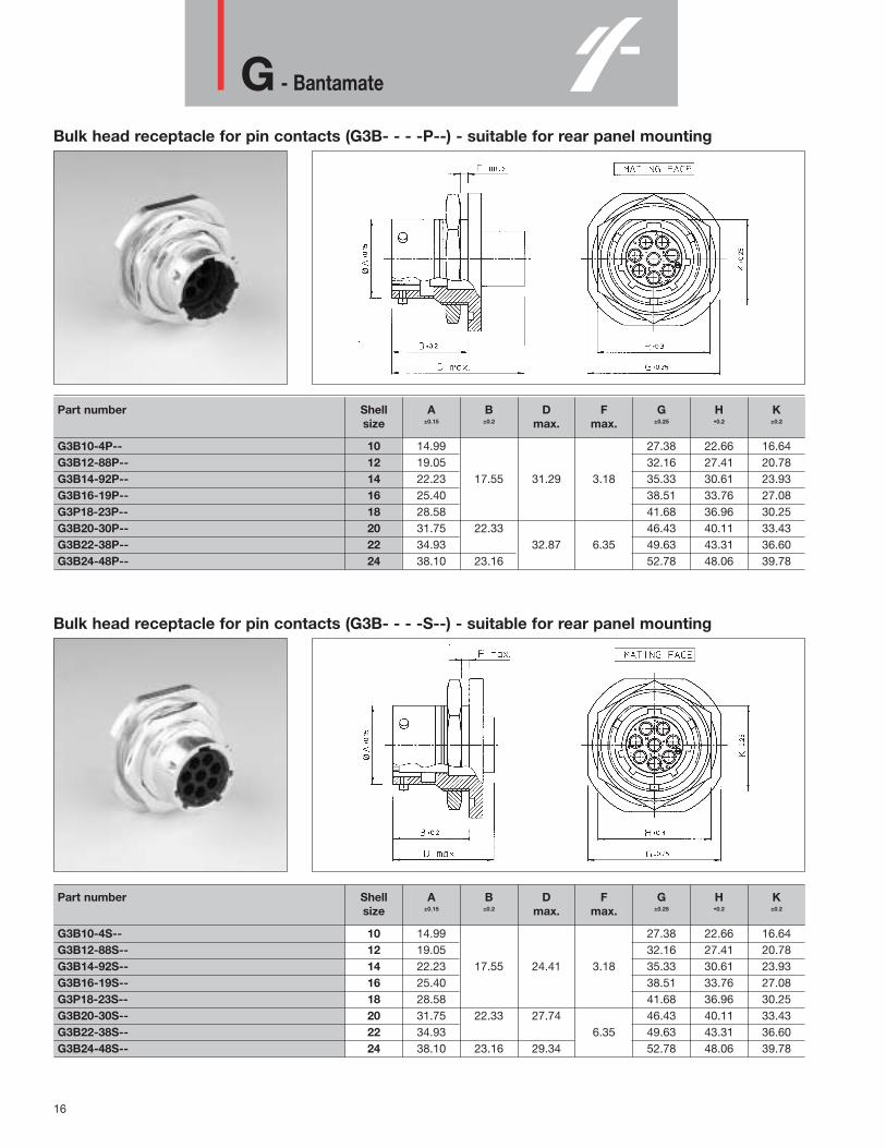
Bulk head receptacle for pin contacts (G3B- - - -P--) - suitable for rear panel mounting
Part number Shell A B D F G H Ksize ±0.15 ±0.2 max. max. ±0.25 •0.2 ±0.2
G3B10-4P-- 10 14.99 27.38 22.66 16.64G3B12-88P-- 12 19.05 32.16 27.41 20.78G3B14-92P-- 14 22.23 17.55 31.29 3.18 35.33 30.61 23.93G3B16-19P-- 16 25.40 38.51 33.76 27.08G3P18-23P-- 18 28.58 41.68 36.96 30.25G3B20-30P-- 20 31.75 22.33 46.43 40.11 33.43G3B22-38P-- 22 34.93 32.87 6.35 49.63 43.31 36.60G3B24-48P-- 24 38.10 23.16 52.78 48.06 39.78
Bulk head receptacle for pin contacts (G3B- - - -S--) - suitable for rear panel mounting
Part number Shell A B D F G H Ksize ±0.15 ±0.2 max. max. ±0.25 •0.2 ±0.2
G3B10-4S-- 10 14.99 27.38 22.66 16.64G3B12-88S-- 12 19.05 32.16 27.41 20.78G3B14-92S-- 14 22.23 17.55 24.41 3.18 35.33 30.61 23.93G3B16-19S-- 16 25.40 38.51 33.76 27.08G3P18-23S-- 18 28.58 41.68 36.96 30.25G3B20-30S-- 20 31.75 22.33 27.74 46.43 40.11 33.43G3B22-38S-- 22 34.93 6.35 49.63 43.31 36.60G3B24-48S-- 24 38.10 23.16 29.34 52.78 48.06 39.78

17
UTG - Metalok Bantam
Plastic connector withmetal couplingsystem
Description“UTG” Metalok Bantam plastic industrialcircular connectors with metal coupling area range of multiway connectors to providethe complete answer to the need forleightweight, robust circular connectors.They are available in 8 shell sizes, 11 insertarrangements all intermateable,interchangeable and intermountable with theTrim-Trio “UT0” and “UTP industrialconnector families.
Features and benefits• Available in 8 shell sizes and 11 insert
arrangements incl. 3 VDE versions and onepower version.
• Available in plug and receptacle versionsfor both male and female contacts.
• Connectors and accessories are mouldedfrom highly durable glass-filledthermoplastic.
• Flammability rating: UL94-V0.• UL approved-file Nr.: E31151• Metal bayonet ring:
- Metal wave spring loaded.- Locks with audible positive “click” - Assures 500 matings and unmatings
Performance characteristicsOperating temperature: -55°C to +125°C Insulation resistance: 5000 MΩ min.Test potential: 2000 VACDurability: 500 matings and unmatings. Vibration Per MIL-STD202resistance: method 204Thermal Per MIL-STD202shock: method 207Degree of protection per DIN 40050:IP65 in mated condition. “H” version used with UTG —PG cable clamp
ConstructionConnector body
Glass filled thermoplast UL94-V0Colour: black
Coupling ring: Nickel plated brassTri-lock pins: Stainless steelCoupling spring: Spring steel
Contact accommodation • “UTG” connectors accept Trim-Trio crimp-
type removable snap-lock contacts (seecontact section)
• Contacts to be ordered seperately.
How to order
- -- -
BB
- -- -N
PS
1212
1414
06
UTGUTG
Connector family :
Body variation: 0 : Wall mounting receptacle6 : Cable plug1 : Free hanging receptacle
Shell size:
Insert arrangement:
Type of contacts: P : Pin contactsS : Socket contacts
Plating N : Nickelplated bayonet ring (Plug Part Numbers Only)
Application No letter : Standard versionH : Water protected version (only receptacle)
Design variation No letter : Moulded-in contact marking (standard version)Others : Specials versions
Packing: No letter: Standard version: Each connector individualy packed in plastic bagB: Bulk packing per qty of 100 pcs
UT
G

18
UTG - Metalok Bantam
Cable plug for pin contacts (UTG6- - - -PN)
Part number Shell Ø A ±0.2 B max. Ø C ±0.15 Ø D ±0.15 E ±0.2
size
UTG6104PN / UTG6103PNVDE 10 21.6 10.9 12.2UTG6128PN 12 24.8 13.8 15.1UTG61412PN 14 28.0 31.8 17.0 18.3UTG61619PN 16 31.2 19.9 21.5 19.1UTG61823PN / UTG6187PNVDEU 18 34.3 31.8 / 33.0 22.4 24.0UTG62028PN / UTG62020PN 20 37.5 31.8 / 35.3 25.6 27.2UTG62235PN 22 40.7 31.8 26.5 30.4UTG62448PN 24 43.9 31.7 33.5
Cable plug for socket contacts (UTG6- - - -SN)
Part number Shell Ø A ±0.2 B max. Ø C ±0.15 Ø D ±0.15 E ±0.2
size
UTG6104SN / UTG6103SNVDE 10 21.6 23.9 / 26.75 10.9 12.2UTG6128SN 12 24.8 13.8 15.1UTG61412SN 14 28.0 23.9 17.0 18.3UTG61619SN 16 31.2 19.9 21.5 19.1UTG61823SN / UTG6187SNVDEU 18 34.3 23.9 / 29.0 22.4 24.0UTG62028SN / UTG62020SN 20 37.5 24.9 25.6 27.2UTG62235SN 22 40.7 28.5 30.4UTG62448SN 24 43.9 26.2 31.7 33.5
For bulk packing (qty 100 pcs) add B at the end of cat. Nr. eg. UTG61412PNB
For bulk packing (qty 100 pcs) add B at the end of cat. Nr. eg. UTG61412SNB

19
UTG - Metalok Bantam
Wall mounting receptacle for pin contacts (UTG0- - - -P)
Part number Shell A B C Ø D E F Ø G Ø H Ø Jsize max. ±0.15 ±0.2 ±0.15 ±0.25 •0.25 ±0.1 ±0.1 ±0.1
UTG0104P / UTG0103PVDE 10 15.0 18.3 23.8 17.3 15.1UTG0128P 12 2.3 19.0 20.6 26.2 21.8 18.2UTG01412P 14 31.7 11.3 22.2 23.0 28.6 25.0 21.4UTG01619P 16 25.3 24.6 31.0 3.2 28.1 24.6UTG01823P / UTG0187PVDEU 18 31.7/34.0 2.5 11.3/17.9 28.5 27.0 33.3 31.3 27.8UTG02028P / UTG02020P 20 33.3/34.3 14.5 31.7 29.4 36.5 34.5 30.9UTG02235P 22 33.3 3.5 34.9 31.8 39.7 37.7 34.1UTG02448P 24 15.3 38.0 34.9 42.9 3.9 40.9 37.3
For waterprotected version add “H” behind “P” e.g. UTG01412PH
Wall mounting receptacle for socket contacts (UTG0- - - -S)
Part number Shell A B C Ø D E F Ø G Ø H Ø Jsize max. ±0.15 ±0.2 ±0.15 ±0.25 •0.25 ±0.1 ±0.1 ±0.1
UTG0104S / UTG0103SVDE 10 24.3/27.6 15.0 18.3 23.8 17.3 15.1UTG0128S 12 2.3 19.0 20.6 26.2 21.8 18.2UTG01412S 14 24.3 11.3 22.2 23.0 28.6 25.0 21.4UTG01619S 16 25.3 24.6 31.0 3.2 28.1 24.6UTG01823S / UTG0187SVDEU 18 24.3/30.4 2.5 11.3/17.9 28.5 27.0 33.3 31.3 27.8UTG02028S / UTG02020S 20 27.0 14.5 31.7 29.4 36.5 34.5 30.9UTG02235S 22 28.0 3.5 34.9 31.8 39.7 37.7 34.1UTG02448S 24 30.4 15.3 38.0 34.9 42.9 3.9 40.9 37.3
For waterprotected version add “H” behind “P” e.g. UTG01412SH
For bulk packing (qty 100 pcs) add B at the end of cat. Nr. eg. UTG01412PB
For bulk packing (qty 100 pcs) add B at the end of cat. Nr. eg. UTG01412SB
UT
G

20
UTG - Metalok Bantam
Free hanging receptacle for pin contacts (UTG1- - - -P)
Part number Shell A B ±0.15 C ±0.2 Ø D ±0.15 Ø E ±0.15
size max.
UTG1104P / UTG1103PVDE 10 15.0 19.5UTG1128P 12 19.0 23.5UTG11412P 14 31.7 8.65 22.2 27.0UTG11619P 16 5.0 25.3 30.0UTG11823P / UTG1187PVDEU 18 31.7/34.0 8.65/15.35 28.5 33.0UTG12028P / UTG12020P 20 33.3/34.3 12.05 31.7 36.5UTG12235P 22 33.3 34.9 39.5UTG12448P 24 13.85 38.0 42.5
For waterprotected version add “H” behind “P” e.g. UTG11412PH
Free hanging receptacle for socket contacts (UTG1- - - -S)
Part number Shell A B ±0.15 C ±0.2 Ø D ±0.15 Ø E ±0.15
size max.
UTG1104S / UTG1103SVDE 10 24.3/27.6 15.0 19.5UTG1128S 12 19.0 23.5UTG11412S 14 24.3 8.65 22.2 27.0UTG11619S 16 5.0 25.3 30.0UTG11823S / UTG1187SVDEU 18 24.3/30.4 8.65/15.35 28.5 33.0UTG12028S / UTG12020S 20 12.05 31.7 36.5UTG12235S 22 25.9 34.9 39.5UTG12448S 24 13.85 38.0 42.5
For waterprotected version add “H” behind “P” e.g. UTG11412SH
For bulk packing (qty 100 pcs) add B at the end of cat. Nr. eg. UTG11412PB
For bulk packing (qty 100 pcs) add B at the end of cat. Nr. eg. UTG11412SB

21
UTP - Full plastic Bantam
Full plastic circular Trim Trio connector
Description“UTP” full plastic industrial circular connectors are a range of multiwayconnectors.“UTP” provides the complete answer to theneed for economical leightweight, robustcircular connectors and is unique in offering a plastic bayonet coupling ringincorporating a metal wave spring, whichlocks with an audible positive “click”. It is available in 8 shell sizes, 10 insertarrangements all intermateable,interchangeable and intermountable with the Trim-Trio “UT0” (full metal) and “UTG”(plastic with metal coupling ring) industrialconnector families.
Features and benefits• Available in 8 shell sizes and 10 insert
arrangements incl. 2 VDE versions.• Available in plug and receptacle versions
for both male and female contacts.• Connectors and accessories are moulded
from highly durable glass-filledthermoplastic.
• Flammability rating: UL94-V0.• Plastic bayonet ring:
- Vibration proof thermoplast- Metal wave spring loaded.- Locks with audible positive “click”
Performance characteristicsOperating temperature: -55°C to +125°C Insulation resistance: 5000 MΩ min.Test potential: 2000 VACDurability: 250 matings and unmatings. Degree of protection per DIN 40050:IP65 in mated condition. “H” version used with UTG-PG cable clamp
ConstructionConnector, Bayonet ring and accessories Gass filled thermoplast UL94-V0Colour: blackCoupling spring: Spring steel
Contact accommodation • “UTP” connectors accept Trim-Trio crimp-
type removable snap-lock contacts (seecontacts section)
• Contacts to be ordered seperately.
- -- -
BB
HPS
1212
1414
06
UTPUTP
Connector family :
Body variation: 0 : Wall mounting receptacle6 : Cable plug
Shell size:
Insert arrangement:
Type of contacts: P : Pin contactsS : Socket contacts
Application No letter : Standard versionH : Water protected version (only receptacle)
Design variation No letter : Moulded-in contact marking (standard version)Others : Specials versions
Packing: No letter: Standard version: Each connector individualy packed in plastic bagB: Bulk packing per qty of 100 pcs
How to order
UT
P

22
UTP - Full plastic Bantam
Cable plug for pin contacts (UTP6- - - -P)
Part number Shell Ø A ±0.2 B Ø C ±0.15 Ø D ±0.15 Ø E ±0.2
size max.
UTP6104P / UTP6103PVDE 10 26.7 10.9 12.2UTP6128P 12 31.4 13.8 15.1UTP61412P 14 34.5 31.8 17.0 18.3UTP61619P 16 37.8 19.9 21.5 19.1UTP61823P / UTP6187PVDEU 18 40.8 31.8 / 33.0 22.4 24.0UTP62028P 20 43.9 25.6 27.2UTP62235P 22 47.0 31.8 28.5 30.4UTP62448P 24 50.1 31.7 33.5
Cable plug for socket contacts (UTP6- - - -S)
Part number Shell Ø A ±0.2 B Ø C ±0.15 Ø D ±0.15 Ø E ±0.2
size max.
UTP6104S / UTP6103SVDE 10 26.7 10.9 12.2UTP6128S 12 31.4 13.8 15.1UTP61412S 14 34.5 23.9 17.0 18.3UTP61619S 16 37.8 19.9 21.5 19.1UTP61823S / UTP6187SVDEU 18 40.8 23.9 / 29.0 22.4 24.0UTP62028S 20 43.9 24.9 25.6 27.2UTP62235S 22 47.0 28.5 30.4UTP62448S 24 50.1 26.2 31.7 33.5
For bulk packing (qty 100 pcs) add B at the end of cat. Nr. eg. UTP61412PB
For bulk packing (qty 100 pcs) add B at the end of cat. Nr. eg. UTP61412SB

23
UTP - Full plastic Bantam
Wall mounting receptacle for pin contacts (UTP0- - - -P)
Part number Shell A B C Ø D E F Ø G Ø H Ø Jsize max. ±0.15 ±0.2 ±0.15 ±0.25 •0.25 ±0.1 ±0.1 ±0.1
UTP0104P / UTP0103PVDE 10 15.0 18.3 23.8 15.1UTP0128P 12 2.3 19.0 20.6 26.2 18.2UTP01412P 14 31.7 11.3 22.2 23.0 28.6 21.4UTP01619P 16 25.3 24.6 31.0 3.2 24.6UTP01823P / UTP0187PVDEU 18 31.7/34.0 2.5 11.3/17.9 28.5 27.0 33.3 27.8UTP02028P 20 14.5 31.7 29.4 36.5 30.9UTP02235P 22 33.3 3.5 34.9 31.8 39.7 34.1UTP02448P 24 15.3 38.0 34.9 42.9 3.9 37.3
For waterprotected version add “H” behind “P” e.g. UTP01412PH
Wall mounting receptacle for socket contacts (UTP0- - - -S)
Part number Shell A B C Ø D E F Ø G Ø H Ø Jsize max. ±0.15 ±0.2 ±0.15 ±0.25 •0.25 ±0.1 ±0.1 ±0.1
UTP0104S / UTP0103SVDE 10 24.3/27.6 15.0 18.3 23.8 15.1UTP0128S 12 2.3 19.0 20.6 26.2 18.2UTP01412S 14 24.3 11.3 22.2 23.0 28.6 21.4UTP01619S 16 25.3 24.6 31.0 3.2 24.6UTP01823S / UTP0187SVDEU 18 24.3/30.4 2.5 11.3/19.7 28.5 27.0 33.3 27.8UTP02028S 20 27.0 14.5 31.7 29.4 36.5 30.9UTP02235S 22 28.0 3.5 34.9 31.8 39.7 34.1UTP02448S 24 30.4 15.3 38.0 34.9 42.9 3.9 37.3
For waterprotected version add “H” behind “P” e.g. UTP01412SH
For bulk packing (qty 100 pcs) add B at the end of cat. Nr. eg. UTP01412PB
For bulk packing (qty 100 pcs) add B at the end of cat. Nr. eg. UTP01412SB
UT
P

24
Shielded connectors
Shielded circular TRIM TRIO connectorsUT0 and UTGS
DescriptionWith the increasing coverage of theelectromagnetic spectra and the constantlyincreasing use of electronic hardware, theneed for control on electronic equipment tooperate in electromagnetically noisierenvironments and greater control is one ofthe main issues.More and more electronic equipment will berequired to meet an EMC (Electro MagneticCompatibility) specification which controlsthe level of EM emmisions being upset byinterfering RF (Radio Frequency) and EM(Electro Magnetic) fields.A full solution to the problem consists in theconsideration of each and every aspectwithin a design, starting at the board leveland working outwards through theconnector to the enclosure and then on tothe power supply and signal cabling.As a result, UT0 and UTGS are availablewith shielded backshells including a“ two conical ferrule shielding system”.
Shielding effectiveness is a functionalmethod to characterise the shield leakage,since it offers us the relation between themeasured power progression from shieldingleakage and the reference power deliveredto the test-cel
Test set-upThe measurements are performed with thetriaxial setup.The connectors are embedded in arectangular testcell (see picture)For the circular connectors an innerconductor is contructed to obtain a 50(coaxial transmission line, to which a powerlevel Pin is delivered. The shield of theconnector and the walls from the triaxial cellform the second coaxial transmission line.The output power Pout at one end of the short-circuitedsecond transmission line is measured with aspectrum analyser. From the average ofthese quantities, the shielding effectivenessis calculated (see formula and resultingchart).
Formula: Shielding effectiveness in dB
Shielding effectiveness chart for UT0 and UTGS

25
Shielded connectors
How to assemble shielded connectors ...
Put all parts over the cable, including the coupling ring, as shown on the picture.Strip the outer jacket with the dimensions given in the table.
Recommended cable strip dimensions
Bend the braid backwards over the cable jacket.Strip the wires (refer to contact section).Crimp the contacts.
Insert contact into connector.Slide inner shielding ferrule over the connector.
Bend the braid back over the conical part of the inner shieldingferrule.Cut the shield so that it does not pass the front edge as shown
Wrap shielding around inner shielding ferrule using a conductivetape. .Make sure that the braid is wrapped equally around the ferrule toavoid misalignment when assembled.
SH
IELD
ED
CO
NN
EC
TO
RS

26
Shielded connectors
How to assemble shielded connectors ... (cont.)
Slide coupling ring forwards over the connector.Slide outer shielding ferrule over the shield.Push the cable a little foreward to avoid stress on wires, contactand braid after tightening the PG-tube.
Screw the sealing and the PG-nut into the PG-tube to achieve sealing. Tighten up cable clamp. Note: Tightening the PG-tube with its PG-nut and sealing might twist the
braid.
Shielded connector in assembled condition.
Recommended torque moments to tighten PG-tube onto connector.
Screw the PG-tube onto the connector using a strap wrench. Put the plug in an empty receptacle and fix the receptacle in a bench. Tighten the PG-tube with the recommended torque moments given intable and prevent the cable of twisting.For Strap wrench and torque meters cosult factory.
27
UTGS - Shielded Bantam
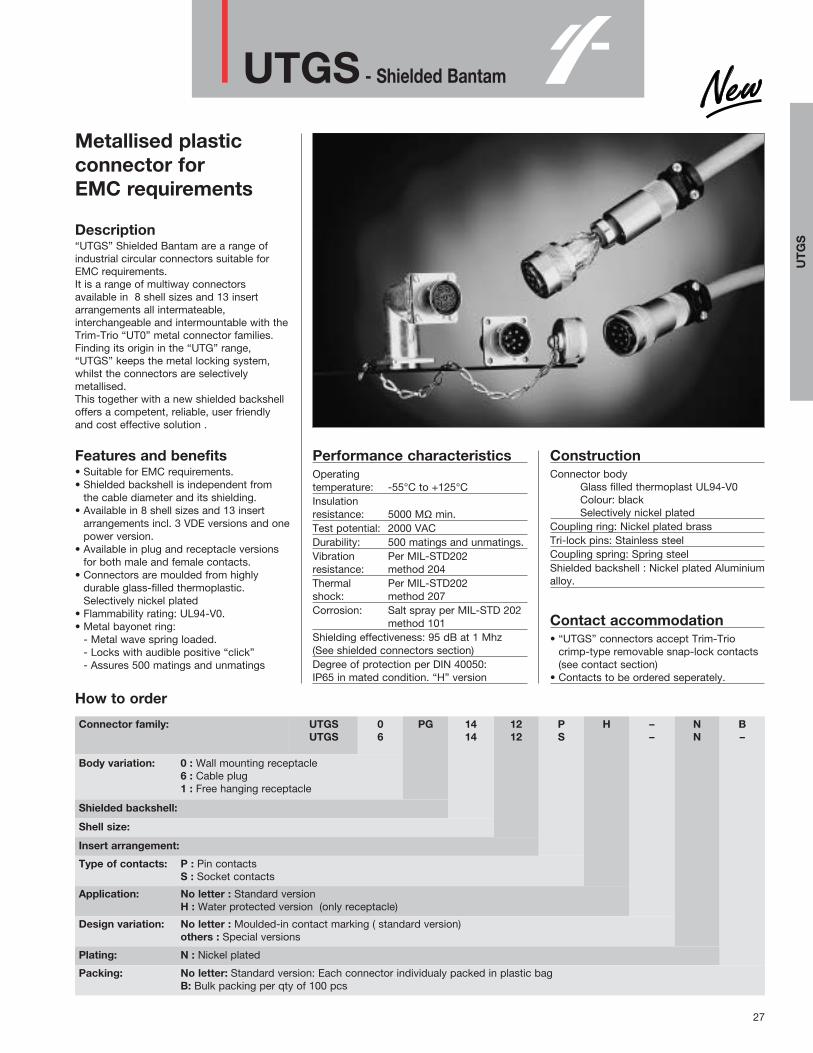
Metallised plasticconnector forEMC requirements
Description“UTGS” Shielded Bantam are a range ofindustrial circular connectors suitable forEMC requirements.It is a range of multiway connectorsavailable in 8 shell sizes and 13 insertarrangements all intermateable,interchangeable and intermountable with theTrim-Trio “UT0” metal connector families.Finding its origin in the “UTG” range,“UTGS” keeps the metal locking system,whilst the connectors are selectivelymetallised. This together with a new shielded backshelloffers a competent, reliable, user friendlyand cost effective solution .
Features and benefits• Suitable for EMC requirements.• Shielded backshell is independent from
the cable diameter and its shielding. • Available in 8 shell sizes and 13 insert
arrangements incl. 3 VDE versions and onepower version.
• Available in plug and receptacle versionsfor both male and female contacts.
• Connectors are moulded from highlydurable glass-filled thermoplastic.Selectively nickel plated
• Flammability rating: UL94-V0.• Metal bayonet ring:
- Metal wave spring loaded.- Locks with audible positive “click” - Assures 500 matings and unmatings
Performance characteristicsOperating temperature: -55°C to +125°C Insulation resistance: 5000 MΩ min.Test potential: 2000 VACDurability: 500 matings and unmatings. Vibration Per MIL-STD202resistance: method 204Thermal Per MIL-STD202shock: method 207Corrosion: Salt spray per MIL-STD 202
method 101Shielding effectiveness: 95 dB at 1 Mhz(See shielded connectors section)Degree of protection per DIN 40050:IP65 in mated condition. “H” version
ConstructionConnector body
Glass filled thermoplast UL94-V0Colour: blackSelectively nickel plated
Coupling ring: Nickel plated brassTri-lock pins: Stainless steelCoupling spring: Spring steelShielded backshell : Nickel plated Aluminiumalloy.
Contact accommodation • “UTGS” connectors accept Trim-Trio
crimp-type removable snap-lock contacts(see contact section)
• Contacts to be ordered seperately.
NN
B–
––
HPS
1212
1414
PG06
UTGSUTGS
Connector family:
Body variation: 0 : Wall mounting receptacle6 : Cable plug1 : Free hanging receptacle
Shielded backshell:
Shell size:
Insert arrangement:
Type of contacts: P : Pin contactsS : Socket contacts
Application: No letter : Standard versionH : Water protected version (only receptacle)
Design variation: No letter : Moulded-in contact marking ( standard version)others : Special versions
Plating: N : Nickel plated
Packing: No letter: Standard version: Each connector individualy packed in plastic bagB: Bulk packing per qty of 100 pcs
How to order
UT
GS

28
UTGS - Shielded Bantam
Shielded cable plug for pin contacts (UTGS6PG- - - -PN)
Part number Shell A B C D Ø E F Maxsize ±0.2 Max. ±0.15 ±0.15 cable Ø
UTGS6PG104PN / UTGS6PG103PNVDE 10 70/74.1 52.2/56.3 12.2 21.6 11.0UTGS6PG128PN 12 74 53.2 15.1 24.8 13.5UTGS6PG1412PN 14 81 58.2 31.8 18.3 28.0 14.5UTGS6PG1619PN 16 84 61.2 19.1 21.5 31.2 16.5UTGS6PG1823PN / UTGS6PG187PNVDEU 18 88/94.4 65.2/71.6 31.8/33.0 24.0 34.3 16.5UTGS6PG2028PN / UTGS6PG2020PN 20 101 70.9 31.8/35.3 27.2 37.5 22.0UTGS6PG2235PN 22 107 76.9 31.8 30.4 40.7 22.0UTGS6PG2448PN 24 120 81.9 33.5 43.9 29.5
- For ass’y procedure see shielded connectors sectionFor bulk packing (qty 100 pcs) add B at the end of cat. Nr. eg. UTGS6PG1412PNB
Shielded cable plug for socket contacts (UTGS6PG- - - -SN)
Part number Shell A B C D Ø E F Maxsize ±0.2 Max. ±0.15 ±0.15 cable Ø
UTGS6PG104SN / UTGS6PG103SNVDE 10 70 / 74.1 52.2 / 56.3 23.9/26.8 12.2 21.6 11.0UTGS6PG128SN 12 74 53.2 15.1 24.8 13.5UTGS6PG1412SN 14 81 58.2 23.9 18.3 28.0 14.5UTGS6PG1619SN 16 84 61.2 19.1 21.5 31.2 16.5UTGS6PG1823SN / UTGS6PG187SNVDEU 18 88 / 94.4 65.2 / 71.6 23.9/29.0 24.0 34.3 16.5UTGS6PG2028SN / UTGS6PG2020SN 20 101 70.9 24.9 27.2 37.5 22.0UTGS6PG2235SN 22 107 76.9 30.4 40.7 22.0UTGS6PG2448SN 24 120 81.9 26.2 33.5 43.9 29.5
- For ass’y procedure see shielded connectors sectionFor bulk packing (qty 100 pcs) add B at the end of cat. Nr. eg. UTGS6PG1412SNB

29
UTGS - Shielded Bantam
Shielded wall mounting receptacle for pin contacts (UTGS0- - - -PN)
Part number Shell A B C Ø D E F Ø G Ø H Ø Jsize max. ±0.15 ±0.2 ±0.15 ±0.25 ±0.25 ±0.1 ±0.1 ±0.1
UTGS0104PN / UTGS0103PNVDE 10 15.0 18.3 23.8 17.3 15.1UTGS0128PN 12 2.3 19.0 20.6 26.2 21.8 18.2UTGS01412PN 14 31.7 11.3 22.2 23.0 28.6 25.0 21.4UTGS01619PN 16 25.3 24.6 31.0 3.2 28.1 24.6UTGS01823PN / UTGS0187PNVDEU 18 31.7/34.0 2.5 11.3/17.9 28.5 27.0 33.3 31.3 27.8UTGS02028PN / UTGS02020PN 20 33.3/34.3 14.5 31.7 29.4 36.5 34.5 30.9UTGS02235PN 22 33.3 3.5 34.9 31.8 39.7 37.7 34.1UTGS02448PN 24 15.3 38.0 34.9 42.9 3.9 40.9 37.3
For waterprotected version add “H” behind “P” e.g. UTGS01412PHNFor bulk packing (qty 100 pcs) add B at the end of cat. Nr. eg. UTGS01412PNB
Shielded wall mounting receptacle for socket contacts (UTGS0- - - -SN)
Part number Shell A B C Ø D E F Ø G Ø H Ø Jsize max. ±0.15 ±0.2 ±0.15 ±0.25 ±0.25 ±0.1 ±0.1 ±0.1
UTGS0104SN / UTGS0103SNVDE 10 24.3/27.6 15.0 18.3 23.8 17.3 15.1UTGS0128SN 12 2.3 19.0 20.6 26.2 21.8 18.2UTGS01412SN 14 24.3 11.3 22.2 23.0 28.6 25.0 21.4UTGS01619SN 16 25.3 24.6 31.0 3.2 28.1 24.6UTGS01823SN / UTGS0187SNVDEU 18 24.3/30.4 2.5 11.3/17.9 28.5 27.0 33.3 31.3 27.8UTGS02028SN / UTGS02020SN 20 27.0 14.5 31.7 29.4 36.5 34.5 30.9UTGS02235SN 22 28.0 3.5 34.9 31.8 39.7 37.7 34.1UTGS02448SN 24 30.4 15.3 38.0 34.9 42.9 3.9 40.9 37.3
For waterprotected version add “H” behind “P” e.g. UTGS01412SHNFor bulk packing (qty 100 pcs) add B at the end of cat. Nr. eg. UTGS01412SNB
UT
GS

30
UTGS - Shielded Bantam
Shielded free hanging receptacle for pin contacts (UTGS1PG- - - -PN)
Part number Shell A B C max D ±0.15 Ø E ±0.2
size
UTGS1PG104PN / UTGS1PG103PNVDE 10 70 / 74.1 52.2 / 56.3 15.0UTGS1PG128PN 12 74 53.2 19.0UTGS1PG1412PN 14 81 58.2 31.7 22.2 8.65UTGS1PG1619PN 16 84 61.2 25.3UTGS1PG1823PN / UTGS1PG187PNVDEU 18 88 / 94.4 65.2 / 71.6 31.7 / 34.0 28.5 8.65 / 15.35UTGS1PG2028PN / UTGS1PG2020PN 20 101 70.9 31.7 12.05UTGS1PG2235PN 22 107 76.9 33.3 34.9UTGS1PG2448PN 24 120 81.9 38.0 13.85
Shielded free hanging receptacle for socket contacts (UTGS1PG- - - -SN)
Part number Shell A B C max D ±0.15 Ø E ±0.2
size
UTGS1PG104SN / UTGS1PG103SNVDE 10 70 / 74.1 52.2 / 56.3 24.3 / 27.6 15.0UTGS1PG128SN 12 74 53.2 19.0UTGS1PG1412SN 14 81 58.2 24.3 22.2 8.65UTGS1PG1619SN 16 84 61.2 25.3UTGS1PG1823SN / UTGS1PG187SNVDEU 18 88 / 94.4 65.2 / 71.6 24.3 / 30.4 28.5 8.65 / 15.35UTGS1PG2028SN / UTGS1PG2020SN 20 101 70.9 31.7 12.05UTGS1PG2235SN 22 107 76.9 25.9 34.9UTGS1PG2448SN 24 120 81.9 38.0 13.85
For waterprotected version add “H” behind “P” e.g. UTGS1PG1412PHNFor bulk packing (qty 100 pcs) add B at the end of cat. Nr. eg. UTGS1PG1412PNB
For waterprotected version add “H” behind “P” e.g. UTGS1PG1412SHNFor bulk packing (qty 100 pcs) add B at the end of cat. Nr. eg. UTGS1PG1412SNB

31
Specials - TRIM TRIO
TRIM TRIO special circularconnectors for: • Mixed power / signal• Boardmount applications
DescriptionBased upon design-in projects, this range ofspecial connectors is an extension of thelong established and popular TRIM TRIOcircular connector series, but with theadvantage of offering a number of additionalfeatures.
Features and benefitsTRIM TRIO connectors suitable for mixedpower / signal application.TRIM TRIO connectors with preloadedstamped and formed contacts forboardmount applicationDesign-in flexibility of TRIM TRIO
UTG size 24-7 with mixedpower / signal contacts.
DescriptionUTG size 24-7 is a standard shell size 24connector with a modified insertarrangement to accept 7 power contacts of3.6mm and 2 TRIM TRIO signal contacts.The power contacts are suitable for currentsup to 44 Amps.The central contact cavity is advancedmoulded for grounding purposes.UTG size 24-7 is VDE 0110 group C - 660Vapproved.
Typical performance characteristicsVDE 0110 Group C - 660 V approved.Central power cavity is advanced forgrounding purposes.For further characteristics refer to UTGseries.
Construction Refer to UTG series.
Power contacts 3.6mm for up to 44 AmpsPower contacts of 3.6mm are available asstandard contacts from the 8P/8PM series.Contacts are for AWG 10, 12 and 14.For all further information such asreferences, plating, crimptooling andextraction tooling refer to the 8P / 8GNcatalog.
TRIM TRIO size 16 signal contactsTrim-Trio crimp-type removable snap-lockcontacts (refer to TRIM TRIO contactssection)
• Contacts to be ordered seperately
UTG size 18-7 with mixedpower / signal contacts.
DescriptionUTG size 18-7 is a standard shell size 18connector with a modified insertarrangement to accept 2 power contacts of2.4mm and 5 TRIM TRIO signal contacts.The power contacts are suitable up to 26Amps and the housings are moulded toobtain 2 mating levels.UTG size 18-7 is per VDE 0110 group C -380V
Typical performance characteristicsPer VDE 0110 Group C - 380 V.2 mating levels.For further characteristics refer to UTGseries.
Construction Refer to UTG series.
Power contacts 2.4mm for up to 26 AmpsPower contacts of 2.4mm are available asstandard contacts from the 8P/8PM series.Contacts are for AWG 26 up to AWG 14.For all further information such asreferences, plating, crimptooling andextraction tooling refer to the 8P / 8GNcatalog.
TRIM TRIO size 16 signal contactsTrim-Trio crimp-type removable snap-lockcontacts (refer to TRIM TRIO contacts section)
• Contacts to be ordered seperately
UTP7 size 12-8 receptacle forboardmount applications
DescriptionUTP7 size 12-8 is a receptacle with a centralbulkhead instead of the standard squareflange with 4 mounting holes.This central bulkhead receptacle is suitablefor rear panel mounting and is preassembledwith size 16 stamped and formed dipsoldercontacts.The receptacle is standard supplied with aferrite ring at the back of the connector forEMC regulations.
Typical performance characteristicsFerrite ring at the back of the connector forEMC regulations.IP67 in mated conditions.For further characteristics refer to UTPseries.
Construction Refer to UTP series.
Performance characteristics for size 16stamped and formed dipsolder contactsCurrent rating 5 AmpsContact resistance 6 m ΩPlating: 0.4µ Au min in contact area, SnPb
on solder tail.
• For receptacle without ferrite ring, right-anglesolder tails or other plating specifications,consult factory
CIR
CU
LAR
SP
EC
IALS

32
Specials - TRIM TRIO
UTG size 24-7 with mixed power / signal contactsCable plug connector for pin contacts. Part number: UTG6247PN
Cable plug connector for socket contacts. Part number: UTG6247SN
Panel mount receptacle for pin contacts. Part number: UTG0247P
Panel mount receptacle for socket contacts. Part number: UTG0247S

33
Specials - TRIM TRIO
UTG size 18-7 with mixed power / signal contactsCable plug connector for pin contacts. Part number: UTG6187PNVDE34
Cable plug connector for socket contacts. Part number: UTG6187SNVDE34
Panel mount receptacle for pin contacts. Part number: UTG0187PVDE34
Panel mount receptacle for socket contacts. Part number: UTG0187SVDE34C
IRC
ULA
R S
PE
CIA
LS

34
Specials - TRIM TRIO
UTP7 size 12-8 receptacle for boardmount applicationsBulkhead panelmount receptacle with straight stamped and formed male dipsolder contacts. Part Number: UTP7128PHSE30K9
Bulkhead panelmount receptacle with right angle stamped and formed male dipsolder contacts. Part Number: Consult factory

35
UTGW - SEALOK
Plastic high densityconnector with metalcoupling Intermateable with MIL-C-26482
VG-9532862GB
Description“UTGW” SEALOK industrial circularconnectors are a range of multiwayconnectors, using N°20 SM-W/SC-WSEALOK contacts with a pin diameter of.040” (1.0mm).This high density connector provides thecomplete answer to the need forleightweight, robust and economical circularconnectors intermateable andintermountable with MIL-C-26482 Series I.62GB and VG-95328 connectors.
Features and benefits• Available in 7 shell sizes and 7 insert
arrangements.• Intermateable with MIL-C-26482 series I,
62GB and VG-95328 connectors.• Plastic connector with metal coupling
system.• Available in cable plug, wall mounting
receptacle and free hanging receptacleversions for both male and femalecontacts.
• Connectors and accessories are mouldedfrom highly durable glass-filledthermoplastic.
• Flammability rating: UL94-V0.• Bayonet ring:
- Metal wave spring loaded.- Locks with audible positive “click”
• Interfacial seal on pin mating face for theultimate in environmental protection.
• Interfacial seals have silkscreened cavitymarking.
Performance characteristicsOperating temperature: -55°C to +125°C Insulation resistance: 5000 MΩ min.Test potential: 2000 V RMSDurability: 500 matings and unmatings. Vibration Per MIL-STD1344Aresistance: Mehod 2004, Condition IIIThermal Per MIL-STD1344Ashock: Method 2005, Condition ASalt spray: Per MIL-STD1344A
Method 1001, 48 hrs (mated)Degree of protection per DIN 40050:IP67 in mated condition used with UTG-ST+ UTG-PG cable clamp
ConstructionConnector body
Glass filled thermoplast UL94-V0Colour: black
Interfacial seal: Neoprene rubberCoupling ring: Nickel plated brassTri-lock pins: Stainless steelCoupling spring: Spring steel
Contact accommodation • “UTGW” connectors only accept SEALOK
crimp type removable snap-lock SM-W /SC-W contacts (see contacts section)
• Contacts to be ordered seperately.
11
BB
PS
1919
1414
06
UTGWUTGW
Connector family
Body variation: 0 : Wall mounting receptacle6 : Cable plug1 : Free hanging receptacle
Shell size:
Insert arrangements:
Type of contacts: P : Pin contactsS : Socket contacts
Design variation: 1 : Interfacial sealing
Packing: No letter: Standard version: Each connector individualy packed in plastic bagB: Bulk packing per qty of 100 pcs
How to order
UT
GW

36
UTGW - SEALOK
Cable plug for pin contacts (UTGW6- - - -P1)
Part number Shell Ø A ±0.2 B Max. Ø C ±0.15 Ø D ±0.15 E ±0.2
size
UTGW6106P1 10 21.6 10.9 12.2UTGW61210P1 12 24.8 13.8 15.1UTGW61419P1 14 28.0 17.0 18.3UTGW61626P1 16 31.2 31.8 19.9 21.5 19.1UTGW62041P1 20 37.5 25.6 27.2UTGW62255P1 22 40.7 26.5 30.4UTGW62461P1 24 43.9 31.7 33.5
Cable plug for socket contacts (UTGW6- - - -S1)
Part number Shell Ø A ±0.2 B Max. Ø C ±0.15 Ø D ±0.15 E ±0.2
size
UTGW6106S1 10 21.6 10.9 12.2UTGW61210S1 12 24.8 13.8 15.1UTGW61419S1 14 28.0 23.7 17.0 18.3UTGW61626S1 16 31.2 19.9 21.5 19.1UTGW62041S1 20 37.5 24.9 25.6 27.2UTGW62255S1 22 40.7 26.5 30.4UTGW62461S1 24 43.9 26.2 31.7 33.5
For bulk packing (qty 100 pcs) add B at the end of cat. Nr. eg. UTGW61419S1B
For bulk packing (qty 100 pcs) add B at the end of cat. Nr. eg. UTGW61419P1B

37
UTGW - SEALOK
Wall mounting receptacle for pin contacts (UTGW0- - - -P1)
Part number Shell A B C Ø D E F Ø G Ø Jsize Max. ± 0.15 ± 0.2 ± 0.15 ± 0.25 ± 0.25 ± 0.1 ± 0.1
UTGW0106P1 10 15.0 18.3 23.8 15.1UTGW01210P1 12 2.3 19.0 20.6 26.2 18.2UTGW01419P1 14 31.7 11.3 22.2 23.0 28.6 21.4UTGW01626P1 16 25.3 24.6 31.0 3.2 24.6UTGW02041P1 20 14.5 31.7 29.4 36.5 30.9UTGW02255P1 22 33.3 3.5 34.9 31.8 39.7 34.1UTGW02461P1 24 15.3 38.0 34.9 42.9 3.9 37.3
Wall mounting receptacle for socket contacts (UTGW0- - - -S1)
Part number Shell A B C Ø D E F Ø G Ø Jsize Max. ± 0.15 ± 0.2 ± 0.15 ± 0.25 ± 0.25 ± 0.1 ± 0.1
UTGW0106S1 10 15.0 18.3 23.8 15.1UTGW01210S1 12 2.3 19.0 20.6 26.2 18.2UTGW01419S1 14 24.3 11.3 22.2 23.0 28.6 21.4UTGW01626S1 16 25.3 24.6 31.0 3.2 24.6UTGW02041S1 20 27.0 14.5 31.7 29.4 36.5 30.9UTGW02255S1 22 28.0 3.5 34.9 31.8 39.7 34.1UTGW02461S1 24 30.4 15.3 38.0 34.9 42.9 3.9 37.3
For bulk packing (qty 100 pcs) add B at the end of cat. Nr. eg. UTGW01419P1B
For bulk packing (qty 100 pcs) add B at the end of cat. Nr. eg. UTGW01419S1B
UT
GW

38
UTGW - SEALOK
Free hanging receptacle for pin contacts (UTGW1- - - -P1)
Part number Shell A B C Ø D Ø Esize Max. ± 0.15 ± 0.2 ± 0.15 ± 0.15
UTGW1106P1 10 15.0 19.5UTGW11210P1 12 19.0 23.5UTGW11419P1 14 31.7 8.65 22.2 27.0UTGW11626P1 16 5.0 25.3 30.0UTGW12041P1 20 12.05 31.7 36.5UTGW12255P1 22 33.3 34.9 39.5UTGW12461P1 24 13.85 38.0 42.5
Free hanging receptacle for socket contacts (UTGW1- - - -S1)
Part number Shell A B C Ø D Ø Esize Max. ± 0.15 ± 0.2 ± 0.15 ± 0.15
UTGW1106S1 10 15.0 19.5UTGW11210S1 12 19.0 23.5UTGW11419S1 14 24.3 8.65 22.2 27.0UTGW11626S1 16 5.0 25.3 30.0UTGW12041S1 20 12.05 31.7 36.5UTGW12255S1 22 25.9 34.9 39.5UTGW12461S1 24 13.85 38.0 42.5
For bulk packing (qty 100 pcs) add B at the end of cat. Nr. eg. UTGW11419P1B
For bulk packing (qty 100 pcs) add B at the end of cat. Nr. eg. UTGW11419S1B

39
UTGW - SEALOK
Intermateable cross reference list SEALOK versus MIL-C-26482 series 1
Sealok P/N Description Crimp 26482 S1 Solder 26482 S1
UTGW6106P1 MS3126*106P MS3116*610PUTGW61210P1 MS3126*1210P MS3116*1210PUTGW61419P1 MS3126*1419P MS3116*1419PUTGW61626P1 Cable plug for pin contacts MS3126*1626P MS3116*1626PUTGW62041P1 MS3126*2041P MS3116*2041PUTGW62255P1 MS3126*2255P MS3116*2255PUTGW62461P1 MS3126*2461P MS3116*2461P
UTGW6106S1 MS3126*106S MS3116*610SUTGW61210S1 MS3126*1210S MS3116*1210SUTGW61419S1 MS3126*1419S MS3116*1419SUTGW61626S1 Cable plug for socket contacts MS3126*1626S MS3116*1626SUTGW62041S1 MS3126*2041S MS3116*2041SUTGW62255S1 MS3126*2255S MS3116*2255SUTGW62461S1 MS3126*2461S MS3116*2461S
UTGW0106P1 MS3120*106P MS3110*610PUTGW01210P1 MS3120*1210P MS31101210PUTGW01419P1 MS3120*1419P MS3110*1419PUTGW01626P1 Wall mounting receptacle for pin contacts MS3120*1626P MS3110*1626PUTGW02041P1 MS3120*2041P MS3110*2041PUTGW02255P1 MS3120*2255P MS3110*2255PUTGW02461P1 MS3120*2461P MS3110*2461P
UTGW0106S1 MS3120*106S MS3110*610SUTGW01210S1 MS3120*1210S MS3110*1210SUTGW01419S1 MS3120*1419S MS3110*1419SUTGW01626S1 Wall mounting receptacle for socket contacts MS3120*1626S MS3110*1626SUTGW02041S1 MS3120*2041S MS3110*2041SUTGW02255S1 MS3120*2255S MS3110*2255SUTGW02461S1 MS3120*2461S MS3110*2461S
*Adaptable to standard 26482 termination
UT
GW

40
Circular - accessories
Plastic cable clamp with strain relief (UTG - - AC)
Part number Shell Cable range Ø A ± 0.4 L ± 0.5
size Ø
UTG10AC 10 3.0 - 8.7 21.0 40.0UTG12AC 12 3.0 - 12.8 24.0 40.0UTG14AC 14 4.0 - 13.8 27.0 46.0UTG16AC 16 5.0 - 17.0 30.2 46.0UTG18AC 18 5.0 - 19.0 33.3 50.0UTG20AC 20 5.0 - 21.0 36.5 55.0UTG22AC 22 5.0 - 23.0 39.7 60.0UTG24AC 24 8.0 - 27.0 42.9 65.0
Plastic cable clamp with strain relief nut for waterprotected (IP65) applications (UTG - - PG)
Part number Shell Sealing* L ± 1 A ± 0.5
size outer dia x inner dia’s
UTG10PG 10 13.5 x 5 x 8 54 21.0UTG12PG 12 16 x 7 x 10.5 x 13 57 24.0UTG14PG 14 18.5 x 7 x 105 x 13 x 16 62 27.0UTG16PG 16 20.5 x 8 x 10.5 x 13 x 16 68 30.2UTG18PG 18 20.5 x 8 x 10.5 x 13 x 16 71 33.3UTG20PG 20 26 x 11 x 15 x 18 x 22 82 36.5UTG22PG 22 26 x 11 x 15 x 18 x 22 88 39.7UTG24PG 24 35 x 19 x 23 x 27 x 31 103 42.9
*In order to accommodate different cable dia’s, the sealing exisits of different layers which can be pulled out easily.

41
Circular - accessories
Plastic cable clamp with strain relief nut for waterprotected (IP65) applications (UTG--ST)
Part number Shell Cable range Dia. A ± 0.5 L ± 1
size
UTG10ST 10 2 - 6 21.0 64UTG12ST 12 3 - 7 24.0 64UTG14ST 14 6 - 9 27.0 69UTG16ST 16 7 - 12 30.2 72UTG18ST 18 33.3 76UTG20ST 20 9 - 16 36.5 80UTG22ST 22 39.7 86UTG24ST 24 13 - 20 42.9 91
CIR
CU
LAR
AC
CE
SS
OR
IES

42
Circular - accessories
Right angle wall mounting adaptor for receptacle connectors (UT0--RA--)
Part number Shell size A ±0.5 Ø B ±0.25 Ø C ±0.25 Ø D ±0.1 Ø W ±0.1 Ø J ±0.1
UT010RAT 10 43.8 23.8 18.2 14.8 14.9UT012RAT 12 46.2 26.2 20.5 17.9 18.0UT014RAT 14 48.6 28.6 22.9 21.1 21.2UT016RAT 16 51.0 31.0 24.5 24.3 3.2 24.4UT018RAT 18 53.3 33.3 26.9 27.5 27.6UT020RAT 20 56.5 36.5 29.2 30.6 30.7UT022RAT 22 59.7 39.7 31.6 33.8 33.9UT024RAT 24 62.9 42.9 34.8 37.0 3.9 37.1
Metal shrink boot adaptor (UTG--AD)
Part number Shell size Ø A±0.2 B
UTG10AD 10 21.0UTG12AD 12 24.0 19.2UTG14AD 14 27.0UTG16AD 16 30.0 21.5UTG18AD 18 33.3UTG20AD 20 36.5 22.8UTG22AD 22 39.7UTG24AD 24 42.9 21.9
Standard plating is tin. For black anodised plating replace “T” by “AB” e.g. UT012RAABFor waterprotected version with O-seals add “H” e.g. UT012HRAT or UT012HRAAB
Standard plating is anodised black. For tin plating add “T” at the end of the part number e.g. UTG12ADT
43
Circular - accessories
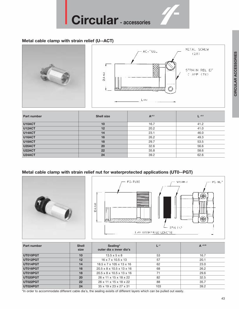
Metal cable clamp with strain relief (U--ACT)
Part number Shell size A±0.2 L ±0.3
U10ACT 10 16.7 41.2U12ACT 12 20.2 41.0U14ACT 14 23.1 46.0U16ACT 16 26.2 49.3U18ACT 18 29.7 53.5U20ACT 20 32.6 56.6U22ACT 22 35.8 58.6U24ACT 24 39.2 62.6
Metal cable clamp with strain relief nut for waterprotected applications (UT0--PGT)
Part number Shell Sealing* L ±1 A ±0.25
size outer dia x inner dia’s
UT010PGT 10 13.5 x 5 x 8 53 16.7UT012PGT 12 16 x 7 x 10.5 x 13 57 20.1UT014PGT 14 18.5 x 7 x 105 x 13 x 16 62 23.0UT016PGT 16 20.5 x 8 x 10.5 x 13 x 16 68 26.2UT018PGT 18 20.5 x 8 x 10.5 x 13 x 16 71 29.6UT020PGT 20 26 x 11 x 15 x 18 x 22 82 32.5UT022PGT 22 26 x 11 x 15 x 18 x 22 88 35.7UT024PGT 24 35 x 19 x 23 x 27 x 31 103 39.2
*In order to accommodate different cable dia’s, the sealing exisits of different layers which can be pulled out easily.
CIR
CU
LAR
AC
CE
SS
OR
IES

44
Circular - accessories
Shielded cable clamp only suitable for UTGS connectors (UTGS----PGN)
Part number Shell Sealing*
For pin contacts For socket contacts size Ø A L outer dia x inner dia’s
UTGS10PGN 10 8.8 54 13.5 x 5 x 8UTGS12PGN 12 12.0 57 16 x 7 x 10.5 x 13UTGS14PGN 14 14.4 62 18.5 x 7 x 105 x 13 x 16UTGS16PGN 16 16.4 68 20.5 x 8 x 10.5 x 13 x 16UTGS18PGN 18 16.8 71 20.5 x 8 x 10.5 x 13 x 16
UTGS20PGPN UTGS20PGSN 20 22.3 82 26 x 11 x 15 x 18 x 22UTGS22PGPN UTGS22PGSN 22 22.3 88 26 x 11 x 15 x 18 x 22UTGS24PGPN UTGS24PGSN 24 30.0 103 35 x 19 x 23 x 27 x 31
*In order to accommodate different cable dia’s, the sealing exisits of different layers which can be pulled out easily.
Shielded cable clamp only suitable for UT0 connectors (UT0S----PG00T)
Part number Shell Sealing*
For pin contacts For socket contacts size Ø A L outer dia x inner dia’s
UT0S10PG00T 10 8.8 54 13.5 x 5 x 8UT0S12PG00T 12 12.0 57 16 x 7 x 10.5 x 13UT0S14PG00T 14 14.4 62 18.5 x 7 x 105 x 13 x 16UT0S16PG00T 16 16.4 68 20.5 x 8 x 10.5 x 13 x 16UT0S18PG00T 18 16.8 71 20.5 x 8 x 10.5 x 13 x 16
UT0S20PGP00T UT0S20PGS00T 20 22.3 82 26 x 11 x 15 x 18 x 22UT0S22PGP00T UT0S22PGS00T 22 22.3 88 26 x 11 x 15 x 18 x 22UT0S24PGP00T UT0S24PGS00T 24 30.0 103 35 x 19 x 23 x 27 x 31
*In order to accommodate different cable dia’s, the sealing exisits of different layers which can be pulled out easily.

45
Circular - accessories
Metal right angle cable clamp with strain relief (L--LE)
Part number shell size A max B max C max Cable range
L10LE 10 18.3 61.4 64.0 7.2 - 11.1L12LE 12 21.4 63.1 66.0 9.9 - 14.2L14LE 14 24.7 66.6 75.8 13.0 - 15.8L16LE 16 27.7 76.2 79.2 14.6 - 19.0L18LE 18 31.0 81.6 96.3 17.8 - 23.8L20LE 20 34.1 83.1 97.9 17.8 - 23.8L22LE 22 37.4 87.4 106.6 19.0 - 31.7L24LE 24 40.4 87.4 108.2 19.0 - 31.7
CIR
CU
LAR
AC
CE
SS
OR
IES

46
Circular - accessories
Environmental dustcap for plugs (UTG6--DCG)
Part number Shell size A max. B
UTG610DCG 10 20.0UTG612DCG 12 24.0UTG614DCG 14 27.5 20.8UTG616DCG 16 30.5UTG618DCG 18 33.5UTG620DCG 20 36.5UTG622DCG 22 40.0 22.5UTG624DCG 24 43.0
For dustcap without chain skip “G” e.g. UTG612DC
Metal environmental dustcap for receptacles (UTG--DCG)
Part number Shell size A max.
UTG10DCG 10 20.8UTG12DCG 12 24.9UTG14DCG 14 28.1UTG16DCG 16 31.3UTG18DCG 18 34.4UTG20DCG 20 37.6UTG22DCG 22 40.8UTG24DCG 24 43.9
For dustcap without chain skip “G” e.g. UTG12DC

47
Circular - accessories
Plastic environmental dustcap for receptacles (UTP--DCG)
Part number Shell size Ø A ±0.2 B max.
UTP10DCG 10 26.7 19.3UTP12DCG 12 31.4 20.0UTP14DCG 14 34.5UTP16DCG 16 37.8UTP18DCG 18 40.8 20.2UTP20DCG 20 43.9UTP22DCG 22 47.0UTP24DCG 24 50.1 21.8
For dustcap without chain skip “G” e.g. UTP12DC
Sealing for square flange receptacle (UTFD1-B)
Part number shell size Ø F ±0.1 R ±0.25 S ±0.25 Ø V
UTFD12B 10 15.9 18.3 23.8UTFD13B 12 19.0 20.6 26.2UTFD14B 14 22.2 23.0 28.6UTFD15B 16 25.4 24.6 31.0 3.3UTFD16B 18 28.6 27.0 33.3UTFD17B 20 31.8 29.4 36.5UTFD18B 22 34.9 31.8 39.7UTFD19B 24 38.1 34.9 42.9 4.0
CIR
CU
LAR
AC
CE
SS
OR
IES

MBG - Bantamate II
48
Plastic connector withquick mating feature
DescriptionThe BANTAMATE II cylindrical plasticconnector has been designed for use inapplications requiring a high number ofmating cycles and rapid connections anddisconnections.Bantamate II meets minimum durabilityrequirements of 5000 mating/unmatingcycles by using a unique contact wipingsystem consisting of a lubricant saturatedfoam pad bonded to a spring loadedstripper plate within the receptacle or plug.On mating, the stripper plate is pushed deepinto the connector wiping a thin film oflubricant onto the male contacts.A distinctive shape provides mating ease inblind or difficult to reach applications.Some typical applications would include testequipment, medical diagnostic equipment,or any of the hardware interconnectionsfound in the modern electronic office.
Features and benefits• 5000 mating / unmating cycles• Lubricated male contacts with spring
actuated foam plate• Quick and easy installation with latching
mechanism• Easy mating due to the positive
polarisation, even in blind spots• Unmated male contacts are protected by
the spring actuated plate• Available with 4, 12, 19, 30, and 46
contact positions.• Applicable for front or rear panel mounting
as well as free hanging applications• UL recognised File number E31151• CSA certified LR54977
Performance characteristicsOperating temperature: -55°C to +125°C Insulation resistance: 5000 MΩ min.Test potential: 2000 VACDurability: Min. 5000 matings cycles Vibration 5-50Hz, 0,5 dA; 8 hours axisresistance: Thermal 5 cycles -55°C to +105°Cshock: Humidity: 10 days at 85% RH, +85°C
ConstructionConnector body and strain relief:
Glass filled thermoplast UL94-V0Colour: black
Locking latch Stainless steel,and hook: passivated Compression Spring: Music wire, Nickel platedLubricating pad: Polyurethane foamRivet: Brass, Tin platedStrain relief screws:Steel, Cadmium plated
Contact accommodation • “MBG” connectors accept Trim-Trio
crimp-type removable snap-lock contacts(see contact section)
• Contacts to be ordered seperately.
How to order
1P12MBGConnector family
Insert arrangement: 4, 12, 19, 30, 46 positions
Body variation: P: Plug bodyR: Receptacle bodyS: Strain relief
Design variation: 1: Standard version with male contacts in receptacle11: Reversed version with male contacts in plug

MBG - Bantamate II
49
Female plug connector for socket contacts (MBG--P1) - Standard versionMale plug connector for pin contacts (MBG--P11) - Reversed version
Part numberØ A ±0.25 B ±0.25Female plug
Male plug
MBG4P1MBG4P11 15.08 21.90
MBG12P1MBG12P11 19.43 27.25
MBG19P1MBG19P11 22.83 30.53
MBG30P1MBG30P11 27.94 35.51
MBG46P1MBG46P1 34.42 41.91
Panel mounting male receptacle connector for pin contacts (MBG--R1) - Standard versionPanel mounting female receptacle connector for socket contacts (MBG--R11) - Reversed version
Part numberØ A ±0.25 B max. C ±0.18 D ±0.30 Ø E ±0.18 F max.Male Receptacle Female Receptacle
MBG4R1MBG4R11 23.90 18.08 31.45 37.36 20.07 29.46
MBG12R1MBG12R11 32.49 26.54 30.76 36.86 24.64 34.93
MBG19R1MBG19R11 32.44 26.54 34.04 40.13 27.86 38.10
MBG30R1MBG30R11 35.61 28.65 38.00 44.91 38.10 43.31
MBG46R1MBG46R11 42.24 35.13 46.94 54.05 39.70 49.61
MB
G

MBG - Bantamate II
50
Strain relief (MBG--S1)
Part number Ø C Ø D E F Cable range Ø G Cable range Ø Gside A side B
MBG4S1 12.2 15.0 20.1 5.3 8.51/6.35 –MBG12S1 18.8 21.1 26.4 7.9 11.30/7.65 14.99/11.38MBG19S1 21.3 24.4 29.0 9.4 13.08/8.66 17.53/13.12MBG30S1 26.7 29.0 34.5 16.3 19.02/15.88 22.86/19.05MBG30S2 26.7 29.0 34.5 15.9 12.67/10.01 15.85/12.70MBG46S1 Not available
Insert arrangements and moulded-in contact identification
Contact identification positions shown are for mating face of plug and wiring face of receptacle.

MBG - Bantamate II
51
Panel cut-out dimensions for receptacle - Standard version (MBG--R1)
Part number Fig. J K L M N
MBG4R1 1 20.86 27.41 18.08 31.45 10.16MBG12R1 2 25.30 32.74 26.54 30.76 11.65MBG19R1 2 28.50 35.89 34.04 13.32MBG30R1 2 33.73 40.97 28.65 38.00 15.49MBG46R1 2 40.36 47.22 35.13 46.94 18.85
Panel cut-out dimensions for receptacle - Reversed version (MBG--R11)
Part number Fig. J K L M N
MBG4R11 1 20.86 27.41 18.08 31.45 10.16MBG12R11 2 25.30 32.74 26.54 30.76 11.65MBG19R11 2 28.50 35.89 34.04 13.32MBG30R11 2 33.73 40.97 28.65 38.00 15.49MBG46R11 2 40.36 47.22 35.13 46.94 18.85
MB
G

Rectangular
52
Overview rectangular TRIM TRIO connectors
Selection matrix Rectangular connectors

MS-M - Hyfen rectangular
53
High performance hyfen rectangularcable connectors
DescriptionMSM rectangular connectors offers anextremely reliable, rugged, and versatileconnection system .They are a range of multiway connectorsavailable in 8 sizes from 14 to 104 positions.MS-M cable connectors can be offered witha full range of hardware and accessories.Guiding pins and sockets, turnablejackscrews, a variety of cable hoods, pinprotection shrouds and discrimination pinsmake this connector range a truly versatilesystem.
Features and benefits• Connectors supplied pre-assembled
except for panel mount versions.• Available in 14-20-26-34-42-50-75 and
104 positions.• 34 contact positions suitable for V.35
applications (see V.35 section)• Full range of accessories available
including hoods, strain relief clamps, guidepins, jackscrews and pin protectionshrouds.
• MS-M hyfen complies with NFC 93426 -HE 621-622 and MIL-C-28748specifications.
Performance characteristicsOperating temperature: -55°C to +125°C Insulation resistance: 5000 MΩ min.Test potential: 2000 VACDurability: 500 matings and
unmatings.Vibration Per MIL-STD 202resistance method 204Shock: Per MIL-C-STD 202
method 207
ConstructionConnector Material : Glass filled PhenolicFlammability rating : UL94-V0Hoods: Aluminium alloy - anodizedCable clamps: Stainless steelPolarizing hardware: Brass nickel platedShrouds: Aluminium alloy
colour less anodized
Contact accommodation • “MS-M” Hyfen connectors accept Trim-
Trio crimp-type removable snap-lockcontacts (see contact section)
• Contacts to be ordered seperately.
How to order
MSMSD
14 PM 1 S9Series
Connector Density: 14-20-26-34-42-50-75
Plug/Receptacle: PM-RM
Variation Number:
Accessories/Shroud:
MS
-M

MS-M - Hyfen rectangular
54
Contact arrangement
The contact pos i t i on i dent i f i ca t i on l e t te r s o r numbers shown i n the above d i ag rams app ly toMS-M p l ug and receptac l e connecto rs . D imens iona l l y , co r respond ing types o f p l ug and receptac l emou ld i ngs a re the same and d i f f e r on l y i n tha t the contact pos i t i on l e t te r i ng/number i ng o f thep lug (MS-PM) i s a m i r ro r image o f tha t o f the receptac l e (MS-RM) . Note tha t p i ns and/o r socketscan be used i n e i the r the p l ug o r r eceptac l e mou ld i ng .
Note : Contact i dent i f i ca t i on i s shown fo r w i r i ng f ace o f the receptac l e and mat i ng f ace a tp l ug connecto r .

MS-M - Hyfen rectangular
55
Panel mount connectors with guiding hardware (MS--M1)
Part numberConnector Plug version for Receptacle version for A B D E Fig.
size male contacts female contacts14 MS14PM1 MS14RM1 23.8 31.8 20.1 11.720 MS20PM1 MS20RM1 31.75 39.65 27.95 11.7 1-226 MS26PM1 MS26RM1 33.3 41.3 27.2 15.034 MS34PM1 MS34RM1 42.8 50.8 35.7 19.0542 MS42PM1 MS42RM1 50.55 58.65 42.9550 MS50PM1 MS50RM1 57.95 65.85 50.85 18.9575 MS75PM1 MS75RM1 28.1 1-3
(*) Complete part number with “S” for connector with protective shroud.
Panel mount connectors with fixed jackscrew hardware (MS--M58)
Part numberConnector Plug version for Receptacle version for A B D E Fig.
size male contacts female contacts14 MS14PM58 MS14RM58 23.8 31.8 20.1 11.720 MS20PM58 MS20RM58 31.75 39.65 27.95 11.7 1-226 MS26PM58 MS26RM58 33.3 41.3 27.2 15.034 MS34PM58 MS34RM58 42.8 50.8 35.7 19.0542 MS42PM58 MS42RM58 50.55 58.65 42.9550 MS50PM58 MS50RM58 57.95 65.85 50.85 18.9575 MS75PM58 MS75RM58 28.1 1-3
(*) Complete part number with “S” for connector with protective shroud.
MS
-M

MS-M - Hyfen rectangular
56
Cable connector with metal butterfly hood and guiding hardware (MS--M120)
Part numberConnector Plug version for Receptacle version for A B E G max. H S max. R max. Fig.
size male contacts female contacts14 MS14PM120 MS14RM120 23.8 31.8 11.7 14.7 8.5 820 MS20PM120 MS20RM120 31.75 39.65 48.7 8.5 1-226 MS26PM120 MS26RM120 33.3 41.3 15.0 18 10 934 MS34PM120 MS34RM120 42.8 50.8 19.05 22.2 1342 MS42PM120 MS42RM120 50.55 58.65 56.7 1650 MS50PM120 MS50RM120 57.95 65.85 18.95 19.5 1175 MS75PM120 MS75RM120 28.1 31.8 21 1-3
(*) Complete part number with “S” for connector with protective shroud.
Cable connector with metal butterfly hood and fixed jackscrew hardware (MS--M140)
Part numberConnector Plug version for Receptacle version for A B E G max. H S max. R max. Fig.
size male contacts female contacts14 MS14PM140 MS14RM140 23.8 31.8 11.7 14.7 8.5 820 MS20PM140 MS20RM140 31.75 39.65 48.7 8.5 1-226 MS26PM140 MS26RM140 33.3 41.3 15.0 18 10 934 MS34PM140 MS34RM140 42.8 50.8 19.05 22.2 1342 MS42PM140 MS42RM140 50.55 58.65 56.7 1650 MS50PM140 MS50RM140 57.95 65.85 18.95 19.5 1175 MS75PM140 MS75RM140 28.1 31.8 21 1-3
(*) Complete part number with “S” for connector with protective shroud.

MS-M - Hyfen rectangular
57
MS
-M
MSD104 receptacle cable connector with central jackscrew (MS104RM-)
Connector Part number Orientation of guide socketssize
104 MSD104RM489 A, B, C, D
Other orientations of guide sockets on request
MSD104 plug cable connector without cable clamp (MS104PM-)
Connector Part number Orientation of guide socketssize
104 MSD104PM494 A, B, C, D
Other orientations of guide sockets on request

MS-M - Hyfen rectangular
58
MS104 cable connector with cable clamp (MS104PM-)
Connector Part number Orientation of guide pinssize
MS-M panel cut-out dimensions
Connector Fig. A B C D E Fsize
14 1 or 2 12.45 20.83 23.8020 1 or 2 12.45 28.70 31.7526 2 or 3 15.75 28.20 33.3234 4 36.60 42.82 49.3042 4 19.81 43.70 50.55 56.90 6.35 11.8950 4 51.56 57.95 64.3075 4 29.08 14.22 19.40
104 5 29.46 55.63 63.50 72.64 12.70 20.62
104 MS104PM494(*)GE10 A, B, C, D
Other orientations of guide sockets on request(*) Complete part number with “S” for connector with protective shroud.

MSO - Rectangular boardmount
59
Rectangular boardmountconnectors to mate withMSM cable connectors
DescriptionThe MSO series, derived from the MSMseries, is for straight or right-angledapplication on a printed circuit board.Pre-assembled MSO connectors with pin orsocket N(16 contacts are intermateable withthe existing MSM rectangular cableconnectors.The N° 16 TRIM TRIO .0625” (1.6mm)diameter contacts are available in eithersolid machined or stamped and formedversions.The polarizing hardware can be delivered ineither guiding or jackscrew versions.
Features and benefits• Connectors supplied pre-assembled with
dip solder contacts.• Contacts available in solid machined or
stamped and formed version.• Available in 9-18-34-50-75 positions.• For right-angled versions, there is a choice
of 9-18 and 34 contact positions.• 34 contact positions suitable for V.35
applications (see section V.35)• Polarising hardware prevent mismating.• UL94-V0 rated thermoplast.
Performance characteristicsOperating temperature: -55°C to +125°C Current rating: 7.5 AmpContact resistance: 3 mΩInsulation resistance: 5000 M min.Test potential: 2000 VACOperating voltage: 750 V RMSDurability: 500 matings and unmatings.
ConstructionConnector Material : Glass filled polysulfoneFlammability rating : UL94-V0Polarizing hardware: Brass nickel platedContacts: High conductive copper alloy
Plating tablePlating for solid machined contacts:
No digit (std) = Min. 0.4 µ Gold all over, over Nickel.
J = Gold flash all over, over Nickel.T = 3 - 5µ Tin all over
Plating for Stamped and formed contacts :K9 (std) = Min. 0.4µ Gold in contact
area,3 - 5µ SnPb on solder tail.
T = 3 - 5µ Tin all over
Intermateability • “MSO” with pre-assembled contacts are
intermateable with the “MSM” rectangularcable connectors equipped with Trim-Triocrimp-type removable snap-lock contacts(see contact section)
• Contacts to be ordered seperately.
How to order
MSO 34 M R G 58 SE1 K9Connector family
Contact arrangement
N° 16 contacts
Type of housing P: Plug body with male contacts R: Receptacle body with female contacts
Contact termination K: straight dipsolderG: Right angle dipsolder
Type of hardware 1: Guide pin and socket 58:Threaded jackscrew pin and socket
Design variation E1: Solid machined contactsSE1:stamped and formed contacts
Plating indication
MS
O

MSO - Rectangular boardmount
60
Straight boardmount with guiding hardware (MSO--M-K1--)
Part numberconnector Version with Version with
size solid machined contacts stamped and formed contacts A B C
male female male female9 MSO9MPK1E1 MSO9MRK1E1 MSO9MPK1SE1K9 MSO9MRK1SE1K9 9.5 33.3 25.418 MSO18MPK1E1 MSO18MRK1E1 MSO18MPK1SE1K9 MSO18MRK1SE1K9 15.234 MSO34MPK1E1 MSO34MRK1E1 MSO34MPK1SE1K9 MSO34MRK1SE1K9 19.0 50.8 42.850 MSO50MPK1E1 MSO50MRK1E1 MSO50MPK1SE1K9 MSO50MRK1SE1K9 18.9 65.8 57.975 MSO75MPK1E1 MSO75MRK1E1 MSO75MPK1SE1K9 MSO75MRK1SE1K9 19.4
For other platings: See plating table. Other solder tail lengths on request Selective loading on request
Straight boardmount with jackscrew hardware (MSO--M-K58--)
Part numberconnector Version with Version with
size solid machined contacts stamped and formed contacts A B C
male female male female9 MSO9MPK58E1 MSO9MRK58E1 MSO9MPK58SE1K9 MSO9MRK58SE1K9 9.5 33.3 25.418 MSO18MPK58E1 MSO18MRK58E1 MSO18MPK58SE1K9 MSO18MRK58SE1K9 15.234 MSO34MPK58E1 MSO34MRK58E1 MSO34MPK58SE1K9 MSO34MRK58SE1K9 19.0 50.8 42.850 MSO50MPK58E1 MSO50MRK58E1 MSO50MPK58SE1K9 MSO50MRK58SE1K9 18.9 65.8 57.975 MSO75MPK58E1 MSO75MRK58E1 MSO75MPK58SE1K9 MSO75MRK58SE1K9 19.4
For other platings: See plating table. Other solder tail lengths on request Selective loading on request

MSO - Rectangular boardmount
61
Right angle boardmount with guiding hardware (MSO--M-G1--)
Part numberconnector Version with Version with
size solid machined contacts stamped and formed contacts A B C D E F
male female male female9 MSO9MPG1E1 MSO9MRG1E1 33.3 23.0 38.0 16.0 10.0 25.418 MSO18MPG1E1 MSO18MRG1E1 18.034 MSO34MPG1E1 MSO34MRG1E1 MSO34MPG1SE1K9 MSO34MRG1SE1K9 50.8 19.3 55.5 20.5 10.5 42.8
For other platings: See plating table. Other solder tail lengths on request Selective loading on request
Right angle boardmount with jackscrew hardware (MSO--M-G58--)
Part numberconnector Version with Version with
size solid machined contacts stamped and formed contacts A B C D E F
male female male female9 MSO9MPG58E1 MSO9MRG58E1 33.3 23.0 38.0 16.0 10.0 25.418 MSO18MPG58E1 MSO18MRG58E1 18.034 MSO34MPG58E1 MSO34MRG58E1 MSO34MPG58SE1K9 MSO34MRG58SE1K9 50.8 19.3 55.5 20.5 10.5 42.8
For other platings: See plating table. Other solder tail lengths on request Selective loading on request
MS
O

MSO - Rectangular boardmount
62
MSO recommended drilling hole pattern
Size 9
Size 18

MSO - Rectangular boardmount
63
MSO recommended drilling hole pattern
Size 34
Size 50 Size 75
MS
O

V.35 - interface connectors
64
V.35 DTE/DCEInterface connectorsDescriptionThe Telecommunications StandardizationSector TSS V.35, formerly CCITT V.35 is theinternational standard termed “DataTransmission at 48 Kbps using 60-108 KhzGroup-Band Circuits. It makes use of a 34contact connection system speciallydesigned to be used for DTE/DCE thatinterface to high speed digital carriers foundin computer, modem and telecommunicationindustries.Being part of the TRIM TRIO wide range ofhigh reliable rectangular connectors, MSO34(boardmount connectors) and MS34 (cableconnectors) are in complete compliance tothis specification. To meet this specification, insulators havebeen manufactured with 34 contactpositions which can be loaded with theinternational accepted N° 16 TRIM TRIO.0625” (1.6mm) diameter contacts.The boardmount connectors (MSO34) areavailable in straight and right angle versionsequipped with either solid machined orstamped and formed male / femalecontacts.Filtered connectors are under development.The cable connectors (MS34) can be offeredwith a full range of hardware andaccessories. Guiding pins and sockets,turnable jackscrew system, different cablehoods with strain relief, pin protectionshrouds and discrimination pins make thisconnector range as complete as possible.
Features and benefits• Complete compliance with International
Standards of ISO 2593 for TSS V.35(formerly CCITT V.35) interfacing.
• In compliance with NFC 93426 - HE621-622 and MIL-C-28748 specifications.
• UL recognised.• UL94-V0 rated thermoplastic• Boardmount connectors supplied pre-
assembled with dipsolder contacts ineither: - Male or female contacts.
- Machined or stamped and formed contacts
• either: - Straight or right-angled• Stamped and formed contacts have
selective tin plating on solder tails, thuseliminating extra flux operations.
• Selective loading possible on request.• Filtered versions are under development.
Performance characteristicsOperating temperature: -55°C to +125°C Current rating: 7.5 AmpContact resistance: ≤ 3mΩOperating voltage: 750 V RMSInsulation resistance: 5000 MΩ min.Test potential: 2000 VACDurability: 500 matings and unmatings.
Plating tablePlating for solid machined contacts:
No digit (std) = Min. 0.4µ Gold all over,over Nickel.
J = Gold flash all over, over Nickel.T = 3 - 5µ Tin all over
Plating for Stamped and formed contacts :K9 (std) = Min. 0.4µ Gold in contact
area, 3 - 5µ SnPb on soldertail.
T = 3 - 5µ Tin all over
ConstructionMaterial : Glass-reinforced thermoplasticFlammability rating : UL94-V0Polarising hardware: Brass nickel platedContacts: High conductive copper alloy
Performance characteristicsOperating temperature: -55°C to +125°C Insulation resistatance: 5000 MΩ min.Test potential: 2000 VACDurability: 500 matings and unmatings.Vibration Per MIL-STD 202 resistance: method 204Shock: Per MIL-STD 202
method 207
Contact accommodation• “MS” Cable connectors accept Trim Trio
crimp-type removable snap-lock contacts• Contacts to be ordered separately
ConstructionConnector body: Glass-reinforced PhenolicFlammability rating : UL94-V0Cable hoods: Aluminium alloy or
Polyamide 6.6Cable clamps: Stainless steelProtection Shrouds: Aluminium alloy Polarising hardware: Brass nickel plated
Technical data on MSO34PC-Boardmount connectors
Technical data on MS34Cable connectors
IntermateabilityAll the references mentioned are perfectly intermateable, provided that 1 mated pair existsout of a plug half and a receptacle half.Mated pairs can be made for following applications:- Cable to cable- Cable to panel - Cable to straight or right-angled boardmount

V.35 - interface connectors
65
MSO34 Straight boardmount connectors
Part numberVersion with Version with Description
solid machined contacts stamped and formed contacts
MSO34MPK1E1 MSO34MPK1SE1K9 Guide pin, guide socket and male contacts
MSO34MRK1E1 MSO34MRK1SE1K9 Guide pin, guide socket and female contacts
MSO34MPK58E1 MSO34MPK58SE1K9 Jackscrew pin, jackscrew socket and male contacts
MSO34MRK58E1 MSO34MRK58SE1K9 Jackscrew pin, jackscrew socket and female contacts
For other platings: See plating table Other solder tail lengths on request Selective loading on request
MSO34 Right-angled boardmount connectors
Part numberVersion with Version with Description
solid machined contacts stamped and formed contacts
MSO34MPG1E1 MSO34MPG1SE1K9 Guide pin, guide socket and male contacts
MSO34MRG1E1 MSO34MRG1SE1K9 Guide pin, guide socket and female contacts
MSO34MPG58E1 MSO34MPG58SE1K9 Jackscrew pin, jackscrew socket and male contacts
MSO34MRG58E1 MSO34MRG58SE1K9 Jackscrew pin, jackscrew socket and female contacts
For other platings: See plating table Other solder tail lengths on request Selective loading on request
V.3
5

V.35 - interface connectors
66
MSO34 Shielded right-angle boardmount connectors (under development)For availability consult factory
Under development

V.35 - interface connectors
67
MS34 Cable connectors without strain relief hood
MS34 Cable connectors with cable clamp
Part numberVersion with Version with Description
male contacts female contacts
MS34PM1(*)GE00 MS34RM1(*)GE00 Guide pin and guide socket. No strain relief hood.
MS34PM58(*)GE00 MS34RM58(*)GE00 Jackscrew pin and jackscrew socket. No strain relief hood.
MS34PM007(*)GE00 MS34RM007(*)GE00 Turnable jackscrew pin and turnable jackscrew socket. No strain relief hood.
(*) Complete catalogue number with “ S “ for connector with protective shroud.
Part numberVersion with Version with Description
male contacts female contacts
MS34PM117(*)GE00 MS34RM117(*)GE00 Guide pin, guide socket and cable clamp
MS34PM127(*)GE00 MS34RM127(*)GE00 Jackscrew pin, jackscrew socket and cable clamp
MS34PM107(*)GE10 MS34RM107(*)GE10 Turnable jackscrew pin, turnable jackscrew socket and cable clamp.
(*) Complete catalogue number with “S” for connector with protective shroud.
V.3
5

V.35 - interface connectors
68
MS34 Cable connectors with metal butterfly hood
MS34 Cable connectors with plastic suitcase hood
Part numberVersion with Version with Description
male contacts female contacts
MS34PM120(*)GE00 MS34RM120(*)GE00 Guide pin, guide socket and butterfly hood
MS34PM140(*)GE00 MS34RM140(*)GE00 Jackscrew pin, jackscrew socket and butterfly hood.
MS34PM124(*)GE16 MS34RM124(*)GE16 Turnable jackscrew pin, turnable jackscrew socket and butterfly hood.
(*) Complete catalogue number with “S” for connector with protective shroud.
Part numberVersion with Version with Description
male contacts female contacts
MS34PMEH2(*) MS34RMEH2(*) Guide pin, guide socket and plastic suitcase hood.
MS34PMEH3(*) MS34RMEH3(*) Jackscrew pin, jackscrew socket and plastic suitcase hood.
MS34PMEH0(*) MS34RMEH0(*) Turnable jackscrew pin, turnable jackscrew socket and plastic suitcase hood.
(*) Complete catalogue number with “S” for connector with protective shroud.

V.35 - interface connectors
69
MS34 Cable connector with metal suitcase hood
Part numberVersion with Version with Description
male contacts female contacts
MS34PMEHM(*) MS34RMEHM(*) Anodised hood, plastic strain relief and turnable hardware
MS34PMSEHM(*) MS34RMSEHM(*) Shielded version with nickel plated hood, metal strain relief and turnable hardware
(*) Complete catalogue number with “ S “ for connector with protective shroud.
Contacts arrangement forcable connectors
Panel cut-out forcable connectors
Recommended PCB drillinghole pattern for MSO34
V.3
5
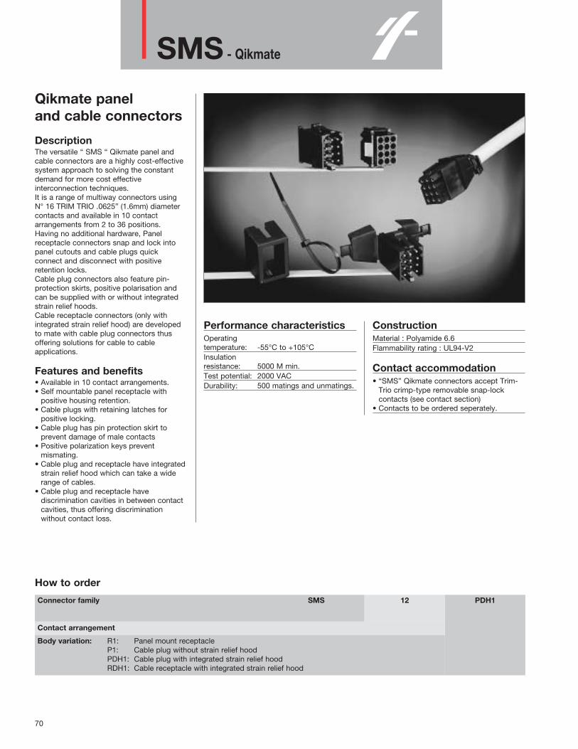
SMS - Qikmate
70
Qikmate paneland cable connectors
DescriptionThe versatile “ SMS “ Qikmate panel andcable connectors are a highly cost-effectivesystem approach to solving the constantdemand for more cost effectiveinterconnection techniques.It is a range of multiway connectors usingN° 16 TRIM TRIO .0625” (1.6mm) diametercontacts and available in 10 contactarrangements from 2 to 36 positions.Having no additional hardware, Panelreceptacle connectors snap and lock intopanel cutouts and cable plugs quickconnect and disconnect with positiveretention locks.Cable plug connectors also feature pin-protection skirts, positive polarisation andcan be supplied with or without integratedstrain relief hoods. Cable receptacle connectors (only withintegrated strain relief hood) are developedto mate with cable plug connectors thusoffering solutions for cable to cableapplications.
Features and benefits• Available in 10 contact arrangements.• Self mountable panel receptacle with
positive housing retention.• Cable plugs with retaining latches for
positive locking.• Cable plug has pin protection skirt to
prevent damage of male contacts• Positive polarization keys prevent
mismating.• Cable plug and receptacle have integrated
strain relief hood which can take a widerange of cables.
• Cable plug and receptacle havediscrimination cavities in between contactcavities, thus offering discriminationwithout contact loss.
Performance characteristicsOperating temperature: -55°C to +105°C Insulation resistance: 5000 M min.Test potential: 2000 VACDurability: 500 matings and unmatings.
ConstructionMaterial : Polyamide 6.6Flammability rating : UL94-V2
Contact accommodation • “SMS” Qikmate connectors accept Trim-
Trio crimp-type removable snap-lockcontacts (see contact section)
• Contacts to be ordered seperately.
How to order
SMS 12 PDH1Connector family
Contact arrangement
Body variation: R1: Panel mount receptacleP1: Cable plug without strain relief hoodPDH1: Cable plug with integrated strain relief hoodRDH1: Cable receptacle with integrated strain relief hood

SMS - Qikmate
71
Contact arrangements for cable plug connectors (SMS--P1 and SMS--PDH1)
Contact identifications shown are for mating face. Contact identifications of wiring face are identical as shown on the receptacle arrangements
SM
S
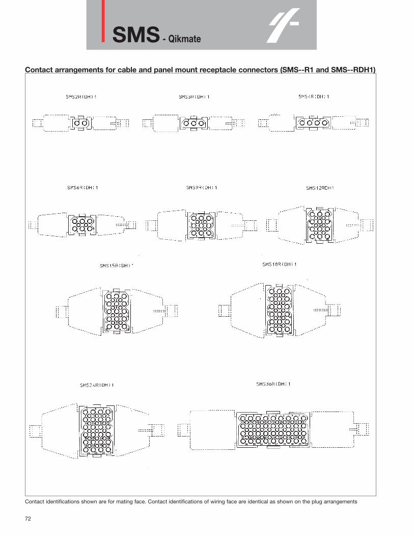
SMS - Qikmate
72
Contact arrangements for cable and panel mount receptacle connectors (SMS--R1 and SMS--RDH1)
Contact identifications shown are for mating face. Contact identifications of wiring face are identical as shown on the plug arrangements

SMS - Qikmate
73
SMS - Standard Qikmate intermateability chart
SM
S
(ONLY IN SIZES3, 6 , 12 AND 18)

SMS - Qikmate
74
Panel mount receptacle (SMS--R1)
Part number Number of A B C max. J ±0.13 K ±0.13
contact pos.
SMS2R1 2 11.0 11.4SMS3R1 3 16.2 5.8 15.2 16.5 11.6SMS4R1 4 21.2 21.7SMS6R1 6 10.9 20.3 16.5 16.7SMS9R1 9 16.0 25.4 21.6SMS12R1 12 16.2 21.1 30.5 26.7SMS15R1 15 26.2 35.6 16.7 31.8SMS18R1 18 31.2 40.6 36.9SMS24R1 24 21.2 21.7SMS36R1 36 46.6 21.1 30.5 47.1 26.7
Cable plug without strain relief hood ( SMS--P1 )
Part number Number of A C max.contact pos.
SMS2P1 2 15.0SMS3P1 3 18.6 17.8SMS4P1 4 23.7SMS6P1 6 22.9SMS9P1 9 27.9SMS12P1 12 18.6 33.0SMS15P1 15 38.1SMS18P1 18 43.2SMS24P1 24 23.7SMS36P1 36 49.1 33.0

SMS - Qikmate
75
Cable receptacle with integrated strain relief hood ( SMS--RDH1 )
Part number Number of Number of A B C D H Cable Recommendedcontact pos. disrimination range unirap
pos. cable te
SMS2RDH1 2 0 31.6 64.8 11.1 0.5 - 8.4SMS3RDH1 3 0 35.1 9.9 69.0 16.2 49..2 0.8 - 7.3 TF4BKDSMS4RDH1 4 0 38.2 74.4 21.2 1.5 - 10.0SMS6RDH1 6 2 34.6 15.0 72.6 50.9 1.7 - 9.2SMS9RDH1 9 4 35.8 20.0 75.3 52.2 3.9 - 14.3SMS12RDH1 12 6 38.1 25.1 72.0 16.2 52.7 4.0 - 15.0SMS15RDH1 15 8 35.9 30.2 81.3 55.2 5.0 - 16.2 TF5BKDSMS18RDH1 18 10 36.1 35.3 5.8 - 20.3SMS24RDH1 24 15 39.7 90.4 21.2 57.2 7.1 - 20.4SMS36RDH1 36 24 54.6 25.1 128.0 46.6 63.3 8.8 - 24.5
Cable plug with integrated strain relief hood ( SMS--PDH1 )
Part number Number of Number of A B C D H Cable Recommendedcontact pos. disrimination range unirap
pos. cable te
SMS2PDH1 2 0 39.5 64.8 14.1 0.5 - 8.4SMS3PDH1 3 0 43.0 16.4 69.0 18.6 57.1 0.8 - 7.3 TF4BKDSMS4PDH1 4 0 46.1 74.4 23.7 1.5 - 10.0SMS6PDH1 6 2 42.5 21.5 72.6 58.8 1.7 - 9.2SMS9PDH1 9 4 43.7 26.7 75.3 60.1 3.9 - 14.3SMS12PDH1 12 6 46.0 31.7 72.0 18.6 60.6 4.0 - 15.0SMS15PDH1 15 8 43.8 36.7 81.3 63.1 5.0 - 16.2 TF5BKDSMS18PDH1 18 10 44.0 41.8 5.8 - 20.3SMS24PDH1 24 15 47.6 90.4 23.7 65.1 7.1 - 20.4SMS36PDH1 36 24 62.5 31.7 128.0 49.1 71.2 8.8 - 24.5
SM
S
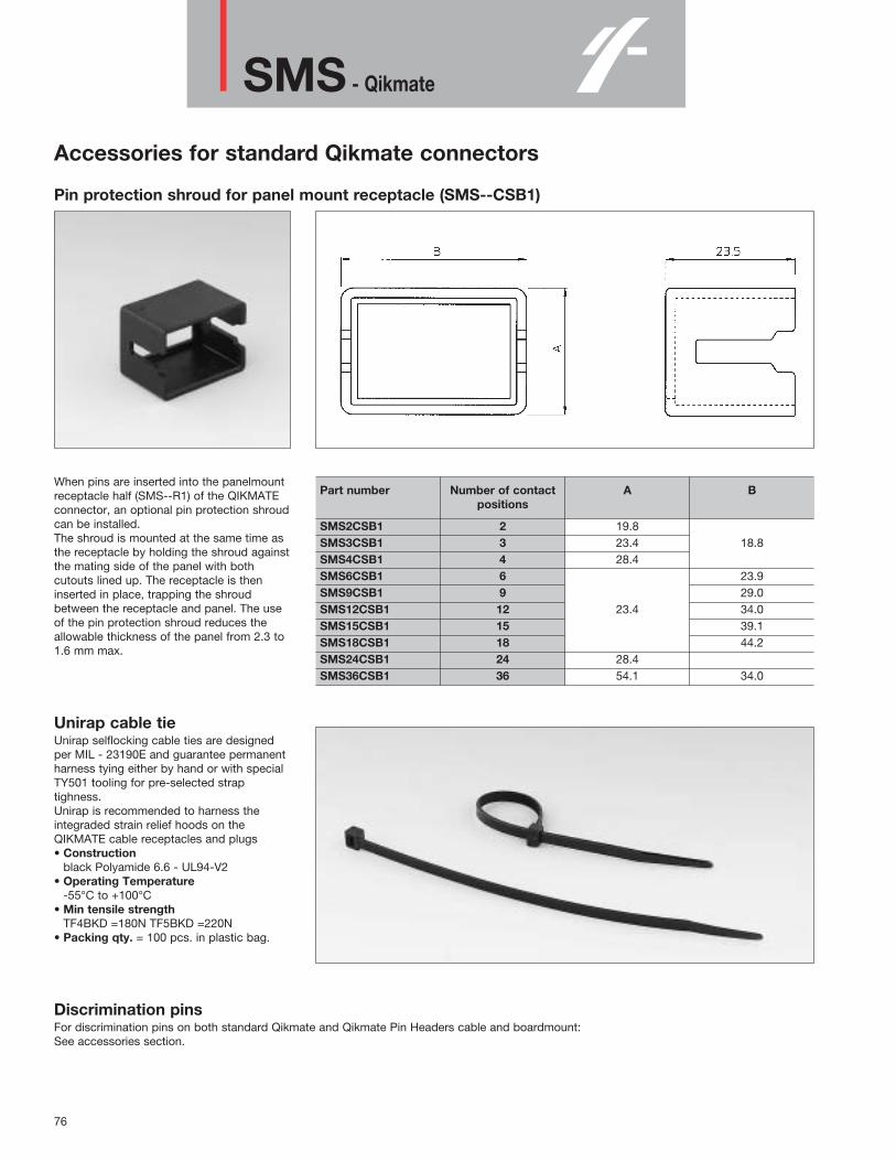
SMS - Qikmate
76
Accessories for standard Qikmate connectors
Pin protection shroud for panel mount receptacle (SMS--CSB1)
When pins are inserted into the panelmountreceptacle half (SMS--R1) of the QIKMATEconnector, an optional pin protection shroudcan be installed.The shroud is mounted at the same time asthe receptacle by holding the shroud againstthe mating side of the panel with bothcutouts lined up. The receptacle is theninserted in place, trapping the shroudbetween the receptacle and panel. The useof the pin protection shroud reduces theallowable thickness of the panel from 2.3 to1.6 mm max.
Unirap cable tieUnirap selflocking cable ties are designedper MIL - 23190E and guarantee permanentharness tying either by hand or with specialTY501 tooling for pre-selected straptighness.Unirap is recommended to harness theintegraded strain relief hoods on theQIKMATE cable receptacles and plugs• Construction
black Polyamide 6.6 - UL94-V2• Operating Temperature
-55°C to +100°C• Min tensile strength
TF4BKD =180N TF5BKD =220N• Packing qty. = 100 pcs. in plastic bag.
Discrimination pinsFor discrimination pins on both standard Qikmate and Qikmate Pin Headers cable and boardmount:See accessories section.
Part number Number of contact A Bpositions
SMS2CSB1 2 19.8SMS3CSB1 3 23.4 18.8SMS4CSB1 4 28.4SMS6CSB1 6 23.9SMS9CSB1 9 29.0SMS12CSB1 12 23.4 34.0SMS15CSB1 15 39.1SMS18CSB1 18 44.2SMS24CSB1 24 28.4SMS36CSB1 36 54.1 34.0

SMS - Boardmount Qikmate
77
Qikmate PC-boardmountconnectors
DescriptionThese PC boardmount connectors enableQIKMATE and preassembled TRIM TRIOcontacts to be PC board mounted, usingconventional solder production techniques.They will then mate and latch with thestandard QIKMATE plugs.Straight boardmount QIKMATE is availablein 10 insert arrangements from 2 to 36positions.Right-angled boardmount Qikmate isavailable in 3, 6, 12 and 18 positions.All boardmount connectors are supplied fullyloaded with pin or socket contacts, either insolid machined or stamped and formedcontacts.Stamped and formed contact have selectivetin plating on the solder tails, thuseliminating flux operations.
Features and benefits• Straight versions available in 10 contact
arrangements from 2 to 36 positions• Right-angled versions available in 3, 6, 12
and 18 positions.• All versions are available with:
- Pin or socket contacts- Stamped and formed or solid machined
contacts.• Some boardmount connectors have
discrimination cavities in between contactcavities, thus offering discriminationwithout contact loss.
Performance characteristicsOperating temperature: -55°C to +125°C Insulation resistance: 5000 M min.Test potential: 2000 VACCurrent rating: 5 AmpDurability: 500 matings and unmatings.
ConstructionConnector body:
Glass filled thermoplastUL94-V2
Contacts: High conductive copper alloy
Plating tablePlating for solid machined contacts:
No digit (std) = Min. 0.4µ Gold all over, over Nickel.
J = Gold flash all over, over Nickel.T = 3 - 5µ Tin all over
Plating for Stamped and formed contacts :K9 (std) = Min. 0.4µ Gold in contact
area, 3 - 5µ Tin on solder tail.T = 3 - 5µ Tin all over
Intermateability • “SMS” Qikmate boardmount connectors
with preassembled TRIM TRIO boarmountcontacts are intermateable only with the“SMS” Qikmate cable plug connectorsequipped with TRIM TRIO crimp typeremovable snap-lock contacts (seecontact section)
How to order
SMSSMS
33
GERE
1212
–Connector family (Self Mountable System)
Contact arrangement
Contact type: GE: Solid machined contactsRE: Stamped and formed contacts
Design variation: 3: Straight boardmount with female contacts4: Straight boardmount with male contacts5: Right angle boardmount with female contacts6: Right angle boardmount with male contacts
Plating indication
SM
S
Plating TablePlating Suffix Description Plating
TR-29 Tin-Alloy Pre-Plated.000005 in (0.13 micron)
D70 Gold over .000075 in Standard(1.9 micron) Nickel
.000030 in (0.75 micron)S6 .Gold over .000075 in Selective
(1.9 micron) Nickel

SMS - Boardmount Qikmate
78
Straight boardmount with female contacts (SMS--GE3 / SMS--RE3S6)
Part number Part number Number of Number of A B C D ESolid machined Stamped and contact pos. discriminationcontacts formed contacts pos.SMS2GE3 SMS2RE3S6 2 0 11.0 - 19.1SMS3GE3 SMS3RE3S6 3 0 16.2 14.0 10.2 5.9SMS4GE3 SMS4RE3S6 4 0 21.3 15.2SMS6GE3 SMS6RE3S6 6 0 19.2 10.9SMS9GE3 Not Available 9 4 24.2 16.0SMS12GE3 SMS12RE3S6 12 0 16.2 29.2 10.2 13.4 21.1SMS15GE3 Not Available 15 8 34.3 26.1SMS18GE3 Not Available 18 10 39.4 31.2SMS24GE3 SMS24RE3S6 24 0 21.2 15.2SMS36GE3 SMS36RE3S6 36 0 46.5 15.2 54.6 20.9
For other platings: see plating table
Straight boardmount with male contacts (SMS--GE4 / SMS--RE4S6)
Part number Part number Number of Number of A B C D ESolid machined Stamped and contact pos. discriminationcontacts formed contacts pos.SMS2GE4 SMS2RE4S6 2 0 11.0 - 19.1SMS3GE4 SMS3RE4S6 3 0 16.2 14.0 10.2 5.9SMS4GE4 SMS4RE4S6 4 0 21.3 15.2SMS6GE4 SMS6RE4S6 6 0 19.2 10.9SMS9GE4 SMS9RE4S6 9 4 24.2 16.0SMS12GE4 SMS12RE4S6 12 0 16.2 29.2 10.2 13.4 21.1SMS15GE4 SMS15RE4S6 15 8 34.3 26.1SMS18GE4 SMS18RE4S6 18 10 39.4 31.2SMS24GE4 SMS24RE4S6 24 0 21.2 15.2SMS36GE4 SMS36RE4S6 36 0 46.5 15.2 54.6 20.9
For other platings: see plating table

SMS - Boardmount Qikmate
79
Right angle boardmount with female contacts (SMS--GE5 / SMS--SE5K9)
Part number Part number Number of Number of A B C D E F GSolid machined Stamped and contact pos. discriminationcontacts formed contacts pos.SMS3GE5 SMS3SE5K9 3 0 16.5 20.5 30.2 24.2 16.2 6.8SMS6GE5 SMS6SE5K9 6 0 19.0 14.4 24.5 11.9SMS12GE5 SMS12SE5K9 12 6 21.6 29.5 35.2 29.2 21.2 17.2SMS18GE5 SMS18SE5K9 18 10 45.4 39.4 31.2
For other platings: see plating tableFor availability on SMS18, consult factory
Right angle boardmount with male contacts (SMS--GE6 / SMS--SE6K9)
Part number Part number Number of Number of A B C D E F GSolid machined Stamped and contact pos. discriminationcontacts formed contacts pos.SMS3GE6 SMS3SE6K9 3 0 16.5 20.5 30.2 24.2 16.2 6.8SMS6GE6 SMS6SE6K9 6 0 19.0 14.4 24.5 11.9SMS12GE6 SMS12SE6K9 12 6 21.6 29.5 35.2 29.2 21.2 17.2SMS18GE6 SMS18SE6K9 18 10 45.4 39.4 31.2
For other platings: see plating tableFor availability on SMS18, consult factory
SM
S
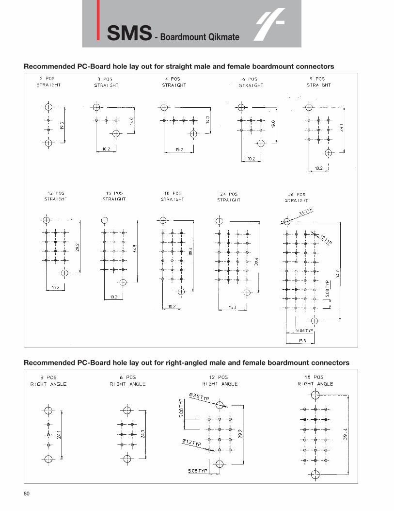
SMS - Boardmount Qikmate
80
Recommended PC-Board hole lay out for straight male and female boardmount connectors
Recommended PC-Board hole lay out for right-angled male and female boardmount connectors

SMS - Qikmate Pin Header
81
Qikmate PC boardmountPin Headers and plugs
DescriptionQikmate Pin Header, available in 3, 4, 6, 9and 10 positions, provides the additionalversatility of straight and right angle boardmounting.Offered as an alternative to stackedconnectors, the in-line contact design of thepin header provides the user with significantPC board space savings.The boardmount receptacle featurespositieve polarization and a moulded on pinprotection skirt and is suppliedpreassembled with straight or right angled:• Solid machined or stamped and formed
PC board pin contacts.• Coax PC board pin contacts.The socket cable plug features positivequick connect / disconnect latches and isdesigned to accept N° 16 TRIM TRIO .0625”(1.6mm) diameter socket contacts formaximum contact protection.
Features and benefits• Available in 3, 4, 6, 9 and 10 positions.• In-line contact design, offering significant
PC board space savings.• Boardmount connectors available in
straight and right-angled versionpreassembled with:- Solid machined or stamped and formed
pin contacts.• - Coax pin contacts.
ConstructionConnector body:
Glass filled thermoplast UL94-V0Colour: Black
Contacts: High conductive copper alloy
Performance characteristicsOperating temperature: -55°C to +125°C Insulation resistance: 5000 MΩ min.Test potential: 2000 VACCurrent rating: 5 AMPDurability: 500 matings and unmatings.
Intermateability • “SMS” Socket plugs accept Trim-Trio
crimp-type removable snap-lock contacts(see contact section)
• Contacts to be ordered seperately.
Plating tablePlating for solid machined contacts:
No digit (std) = Min. 0.4µ Gold all over, over Nickel.J = Gold flash all over,
over Nickel.T = 3 - 5µ Tin all over
Plating for Stamped and formed contacts :S6 (std) = Min. 0.75µ Au in contact area,
Flash on solder tail.D70 = Gold flash all overTR29 = 1.2µ Pre-plated Tin all over.
Plating for coax contacts:Z17 (std) = Min. 0.75µ Au in contact area,
Flash on solder tail (inner)
How to order
SMSSMSSMS
31–
PHCHP3
999
TR29Z17
–
Connector family (Self Mountable System)
Contact arrangement
Contact type: PH: Pin header boardmount.CH: Coax header boardmount.P3: Socket cable plug for pin and coax boardmount header.
Design variation: 1: Right angle coax header boardmount with male contacts.2: Straight coax header boardmount with male contacts3: Right angle pin header boardmount with stamped male contacts4: Straight pin header boardmount with stamped male contactsGE6: Right angle pin header boardmount with machined male contactsGE4: Straight pin header boardmount with machined male contacts
Plating indication
SM
S
Plating TablePlating Suffix Description Plating
TR-29 Tin-Alloy Pre-Plated.000005 in (0.13 micron)
D70 Gold over .000075 in Standard(1.9 micron) Nickel
.000030 in (0.75 micron)D28 .Gold over .000075 in Standard
(1.9 micron) NickelMin. 0.75µ Au in
contact area, Flash on Z17 solder tail (inner) Selective
Min. 0.75µ Au incontact area, Tin onsolder tail (outer)

SMS - Qikmate Pin Header
82
Right angle pin header boardmount with male contacts (SMS--PH3 / SMS--PHGE6)
Part number Part number Number of A B CStamped and Solid machined contactformed contacts contacts positionsSMS3PH3TR29 SMS3PHGE6T 3 31.2 25.4 19.3SMS4PH3TR29 SMS4PHGE6T 4 36.3 30.4 24.4SMS6PH3TR29 SMS6PHGE6T 6 46.5 40.6 34.5SMS9PH3TR29 SMS9PHGE6T 9 61.7 55.9 49.8SMS10PH3TR29 SMS10PHGE6T 10 66.8 61.0 54.9
For other platings: see plating table. Other solder tail lenghts on request
Straight pin header boardmount with male contacts (SMS--PH4 / SMS--PHGE4)
Part number Part number Number of A B CStamped and Solid machined contactformed contacts contacts positionsSMS3PH4TR29 SMS3PHGE4T 3 31.2 25.4 19.3SMS4PH4TR29 SMS4PHGE4T 4 36.3 30.4 24.4SMS6PH4TR29 SMS6PHGE4T 6 46.5 40.6 34.5SMS9PH4TR29 SMS9PHGE4T 9 61.7 55.9 49.8SMS10PH4TR29 SMS10PHGE4T 10 66.8 61.0 54.9
For other platings: see plating table. Other solder tail lenghts on request

SMS - Qikmate Pin Header
83
Right angle coax header boardmount with male contacts (SMS--CH1Z17)
Part number Number of contact A B Cpositions
SMS3CH1Z17 3 31.2 25.4 19.3SMS4CH1Z17 4 36.3 30.4 24.4SMS6CH1Z17 6 46.5 40.6 34.5SMS9CH1Z17 9 61.7 55.9 49.8SMS10CH1Z17 10 66.8 61.0 54.9
For plating spec.: see plating table.
Straight coax header boardmount with male contacts (SMS--CH2Z17)
Part number Number of contact A B Cpositions
SMS3CH2Z17 3 31.2 25.4 19.3SMS4CH2Z17 4 36.3 30.4 24.4SMS6CH2Z17 6 46.5 40.6 34.5SMS9CH2Z17 9 61.7 55.9 49.8SMS10CH2Z17 10 66.8 61.0 54.9
For plating spec.: see plating table.
SM
S

SMS - Qikmate Pin Header
84
Socket cable plug for pin and coax boardmount header (SMS--P3)
Part number Number of contact Dpositions
SMS3P3 3 16.0SMS4P3 4 21.1SMS6P3 6 31.2SMS9P3 9 46.5SMS10P3 10 51.6
Part number of contact E Fpositions
3 10.18 25.404 15.24 30.486 25.40 40.649 40.64 55.8810 45.72 60.96
Recommended PC-board hole layouts

PI 43
85
Wire applications
Description A 43 position two part plug & receptacleconnector system, compatible with Trim-Triocontacts and manufactured to DIN41612style C dimensions. It is used for power & high frequency signaldistribution within a "Eurorack" 19" cardracksystem.
Features and benefits• 19" rack mounted• Designed to DIN41612 style C dimensions• Compatible with Trim-Trio contacts• Contacts are easily replaced• Any combination of different contact styles
can be used within the same housing,including machined, stamped & formedand submix. coax.
Performance characteristics Operating temperature: -55°C to +125°CInsulation resistance: 5000 MΩ min.
ConstructionMaterial: 30% glass filled polyesterFlammability rating: UL94V-OColour: light grey
Contact accomodationP143 connectors accept• RM/RC Machined contacts• SM/SC Formed two-piece contacts• RMDX/RCDX coaxial contacts• Fibre optic contactsContacts to be ordered separately, seecontact section.
Test with 43 mach. contacts / Ø 1,6 mm / 1,5 mm2
Wire to wire derating curve
PI
43

PI 43
86
Plug wire housing with 90° mounting
How to order: PI43G2PTA10P1

PI 43
87
Receptacle wire housing with straight mounting
How to order: PI43G2RTA10P1
PI
43

88
PI 43Boardmount applications
Description The Pl43 boardmount version, derived fromthe wire version, is for direct application ona printed circuit board and manufactured toDIN41612 style C dimensions.The preassembled Pl43 connectors with pinor socket N° 16 contacts are intermateablewith the existing wire ver sions. It is used for power & high frequency signaldistribution within a "Eurorack" 19" cardracksystem.
Features and benefits• Connector supplied preassembled with 43
dipsolder contacts.• Available with pin and socket contacts for
both straight and right-angle terminations.• 19" rack mounted• Designed to DIN41612 style C dimensions.• Selective loading and other termination
lengths optional.
Performance characteristicsOperating temperature: -55°C to +125°CCurrent rating: 7,5 AmpContact resistance: ≤ 3mΩOperating voltage: 750 V RMSTest potential: 2000 VACInsulation resistance: 5000 MΩDurability: 500 cycles
Construction• Connector Body: 30% glass filled
polyester flammability rating: UL94VO colour: light grey
• Contacts: high conductivity copper alloy• Plating: no digit (Std) = 0.4 µ min gold over
nickel - J = gold flash over nickel - N = 0.75µ min gold over nickel - T = 3-5µ Tin
IntermateabilityThe Pl43 boardmount connectors withpreassembled contacts are intermateableonly with the Pl43 wire versionsequipped with:• RC/CM machined contacts• SC/SM formed two piece contacts
Test with 43 mach. contacts / Ø 1,6 mm / 1,5 mm2

89
PI 43Straight boardmount plug
How to order: RPI43G20P5C00 - (standard)
–00CP520RPI43GConnector Family
Contact arrangement: two rows fully loaded
Variations: plug housing with preassembled straightfemale dipsolder contacts
Termination: 4,50 mm
Material: 30% glass filled polyester - colour: grey
Machined contacts
Plating:
PI
43

90
PI 43Right-angle boardmount plug
How to order: RPI43G20PTBF08 - (standard)
–80FPTB20PI43GConnector Family
Contact arrangement: two rows fully loaded
Variations: plug housing with preassembled right-angle maledipsolder contacts
Termination: 2,75 mm
Material: 30% glass filled polyester - colour: grey
Machined contacts
Plating:

91
PI 43Straight boardmount receptacle
How to order: PI43G20RTBC0E - (standard)
–E0CRTB20PI43GConnector Family
Contact arrangement: two rows fully loaded
Variations: plug housing with preassembled straightfemale dipsolder contacts
Termination: 4,50 mm
Material: 30% glass filled polyester - colour: grey
Machined contacts
Plating:
PI
43

92
PI 43Right-angle boardmount receptacle
How to order: RPI43G20R5G00 - (standard)
–00GR520RPI43GConnector Family
Contact arrangement: two rows fully loaded
Variations: plug housing with preassembled right-angle maledipsolder contacts
Termination: 2,75 mm
Material: 30% glass filled polyester - colour: grey
Machined contacts
Plating:

93
PI 43Accessories
Cable hood + Locking keys The cable hood + locking keys offers theopportunity to have a reliable cable strainrelief and an easy locking system betweenthe two mating parts. The hood meets de demand for a fully-insulated compact housing suitable forholding either the male or female half ofconnectors manufactured to DIN41612 styleC dimensions. The locking keys can be chosen in functionof the application and assist in guiding andmatching the two connector halves and alsooffering coding possibilities.
Features and benefits• a strong fully-insulated housing• Exclusion of any mechanical stress on
multi-pin connectors during insertion,operation and withdrawal forces
• 19" rack mounted• Designed to DIN41612 style C dimensions• Three alternative cable outlet positions• Reliable strain relief• Quick mating• Locking keys assist in guiding and coding
Construction• Moulded parts:
- polycarbonate 30% glass filled- colour: hood - lightgrey
Locking keys- black• Flammability rating: UL94V1• Temperature range: -65°C to +125°C• Hardware: surface treated steel
Cable Hood
PI
43

94
PI 43Accessories
How to order: PI96CAP1
For intermateability chart:see next pages
Locking keys

95
PI 43Intermateability chart
No. Type of connection Applicationall 19” rack mounted
A Wire plug to right-angle boardmount rec. Front panel
B Wire plug to right-angle boardmount rec. Back panel
C Wire plug to straight bourdmount rec. Front and back panel
D Wire plug to wire receptacle Front and back panel
E Wire rec. to right-angle bordmount plug Front panel
F Wire rec. to right-angle boardmount plug Back panel
G Wire rec. to straight boardmount plug Front and back panel
H Wire receptacle to wire plug Front and back panel
PI
43
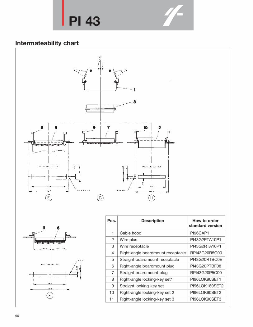
96
PI 43Intermateability chart
Pos. Description How to orderstandard version
1 Cable hood PI96CAP1
2 Wire plus PI43G2PTA10P1
3 Wire receptacle PI43G2RTA10P1
4 Right-angle boardmount receptacle RPI43G20R5G00
5 Straight boardmount receptacle PI43G20RTBC0E
6 Right-angle boardmount plug PI43G20PTBF08
7 Straight boardmount plug RPI43G20P5C00
8 Right-angle locking-key set1 PI96LOK90SET1
9 Straight locking-key set PI96LOK180SET2
10 Right-angle locking-key set 2 PI96LOK90SET2
11 Right-angle locking-key set 3 PI96LOK90SET3

97
Contacts - intro
Overview TRIM TRIO and SEALOK contacts
Selection matrix TRIM TRIO and SEALOK contacts
CO
NT
AC
TS

98
ContactsCurrent ratings for multi-contact connectors
Choice of right connector -contact combination.The choice of a Trim Trio connector incombination with a Trim Trio contact isessential and different for any applicationThere is considerable misunderstanding inthe field on current carrying capabilities forthe various contacts in the TrimTrioprogramme.The intention of this part is to give guidancehow to interprete the given current ratings ingeneral and how to calculate them forparticular applications. The information given is based upon existingMIL specifications such as:MIL-C-26482, MIL-C-8384,MIL-T-7928, MIL-W-5086,MIL-W-5088, MIL-W-16878, etc. and inconjunction with long field practice.
Current carrying capabilitiesTrim Trio contacts are designed to carry aspecific current, in accordance with theapplicable specification.This specification will be defined byfollowing variables:• Connector sizeThe more contacts in a connector, the lesscurrent per contact can be loaded.• Wire size (see table 1)The cross section will determine the internalresistance and temperature rise for a givencurrent. -Table 1 gives the current ratings for thevarious wire sizes commonly used with TrimTrio contacts.• Current rating (see table 2)The current load for a given application willgenerate heat.- Table 2 gives the maximum currentcarrying capacity of most of the Trim Triocontacts, the maximum operating currentand the recommended continuous current.• Ambient temperatureThe combination of the connector size, thewire size and the current rating will generatea temperature rise.This temperature rise + a given ambienttemperature may not exeed the maximumoperating temperature of the connectormaterial (see performance characteristics foreach connector family).
• Max. current carrying capacity• Max. operating current• Recommended continuous currentWhat do these values mean in practice ?
• Max current carrying capacityof a contact is defined by the conductingsection of the contact in its smallest area.The listed values are obtained from severaltests in laboratories under room conditions(21°C). The contact is considered to be infree air.
• Max operating current is the current with which the contacts canbe energized during a longer or shorterperiod, without deteriorating and dependingon working conditions.These are dissipated heat, coolingprovisions, ambient temperature, insulationmaterial, etc.
• Recommended continuous currentcan be applied for all normal cases andworking conditions. The values include asafety margin. However, there arerestrictions in the application of the givenvalues. The most important restriction is theused wire, its sectional area, insulationtemperature range, as well as wires inbundles.Military specifications require that for acable bundle of 15 conductors or more, thebundle shall not carry more than 20% of thetotal carrying capacity of the bundle.In smaller bundles, the allowable percentageof total current may be increased as thebundle approaches the single wire condition.This percentage of increase in total currentcarrying capacity of the bundle is 6% foreach conductor less than 15 in a bundle.
Table 1 - Current carrying capabilities per wire size
Table 2 - Current carrying capabilities per contact type
AWG wire size wire dia. max.curr. max.oper- recomm.mm2 mm carrying ating curr. cont. curr.
Amp. Amp. Amp.26 0.13 0.40 3 2 124 0.20 0.51 4.5 3 222 0.32 0.64 9 5 320 0.52 0.81 11 7.5 518 0.82 1.02 16 10 7.516 1.30 1.29 22 13 1014 2.10 1.63 32 17 13
size pin dia. type max. curr. max. oper- recomm.carying ating curr. cont. curr.Amp. Amp. Amp.
RM / RC 22 13 10machined
16 .062* SM / SC 22 13 101.6 mm 2 piece
stamped20 .040* SM-W / SC-W 11 7.5 5
1.0 mm 2 piecestamped

99
ContactsFrom simple calculations, one can see thatthe closer the bundle approaches the singlewire condition, the higher the allowablecurrent per conductor becomes, to evensuch an extent, that it exceeds therecommended continuous current value. Inthat case, the recommended continuousvalue should have preference. In order tomake this clear, we will give hereafter sometypical examples.
• Example 1Cable bundle, 48 conductors AWG20(0.5mm2) used with circular TrimTrioconnector with insert arrangement 24-48 and machined size 16 contactsRM/RC20.
- Total operating current capacity of bundle 48 x 7.5 A ( table I) = 360 A
- Total allowable capacity for bundles ofmore than 15 wires is 20% = 72 A
- When all conductors are energized equally, this gives: 72 : 48 = 1.5 A per conductor
When for instance 5 conductors areenergized to the recommended continuouscurrent of 5 A (see table 1) resulting in 25 Aconsumption, the other conductors may nottake more than 72 - 25 = 47 A all together, or 1 A perconductor.Any other combination can of course also betaken as long as the total capacity of 72 A isnot exceeded and the recommendedcontinuous current is respected.
RemarkPlease note that contacts used are of thesize 16 type with maximum operatingcurrent of 13 A (table 2).The maximum operating current of thebundle is however restricted to 7.5 A perconductor due to the wire size of AWG20(see table 1).
• Example 2Cable bundle, 14 conductors AWG22 (0.32 mm2) used with rectangular Trim Trio connector with insert arrangementfor 14 contacts, and machined size 16contacts RM / RC20.
- Total operating current capacity of bundle 14 x 5 (table I) = 70 A
- Total allowable for wire bundle of 15 wires less 1 is 20% + 6% = 26%gives 18.2 A.
- All conductors energized equally, gives:18.2 : 14 = 1.3 A per conductor
This value is within the recommended ratingof 3 A so that it can be applied.See also remark under example 1.
• Example 3Cable bundle, 4 conductors AWG16(1.3mm2) used with circular Trim Trioconnector with insert arrangement 10-4 andstamped 2 piece contacts SM /SC.
- Total operating current capacity of bundle 4 x 13 A (table I) = 52 A
- Total allowable for wire bundle of 15 wires less 11 is 20% + 66% = 86%gives 44.7 A.
- All conductors energized equally, gives:44.7 : 4 = 11.2 A per conductor
Since the recommended continuous currentis 10 A, the conductor should not carry morethan 10 A individiually.
As said before, the recommended ratings are valid for most common wiring systems andunder normal working conditions. For extreme conditions, the given values should belowered. The percentage of current reduction should be investigated from case to case. A rule-of thumb which can be used for such cases is:
4 Amp. per mm2 wire section
It gives us for common used wire sizes the values listed in table 3.
26 0.13 0.524 0.20 0.822 0.32 1.320 0.52 2.018 0.82 3.316 1.30 5.214 2.10 8.4
AWG wire size recommendedmm2 continuous
currentAmp.
Table 3 - Recommended continuous current for extreme working conditions
CO
NT
AC
TS

100
ContactsCrimping instructions
The conductor and insulation crimpsectionAre designed to accommodate wire-conductor and insulation diameters,expressed in AWG (American Wire Gauge)or mm2.For each wire gauge, a correct crimprequires a crimp height that offers thehighest performance. This performance is defined as the highesttensile strength force. A good conductor crimp can be guaranteedif the tensile stength force is equal or higheras indicated on the graph below. E.g. aconductor of AWG20 (0.52 mm2) has a goodcrimp if the tensile strength is min 84N.
The tensile strength force is measured inNewtons and is the wire-to-contactconnection that will withstand when astraight axial load is applied to theterminated wire. This is however adestructive test and is thereforeinappropriate as a 100% inspection method.
An alternative method is to measure crimpheight. The crimp height is measured at theconductor-crimp section.• If the dimension is to small, then the
conductor is over-crimped and the wirestrands could be damaged, which resultsin a lower tensile strength force.
• If the dimension is to large, then theconductor is under-crimped and the wirestrands will not be deformed enough toassure that the crimp will pass the tensilestrength test.
In both cases, the application tooling’scrimp height should be adjusted.In order to have the right tooling’s crimpheight go and no-go gauges can beobtained and are defined in function of thetype of crimp tooling and the wire gauge.For further information consult factory.

101
RM/RC - Machined contacts
How to order
D282323
MM
1616
(C) RM(C) RC
Contact type: RM: Male contact bulk packingRC: Female contact bulk packingCRM: Male contact on plastic carrier strip CRC: Female contact on plastic carrier strip
AWG Size: 16, 20, 24, 28, 30Size 16: .0625” (1.6mm) Diameter contactsDesign variation: Crimp barrelPlating indication:
Size 16 solid machinedcontacts for TRIMTRIO connectors
DescriptionSize 16 RM/RC .0625” (1.6mm) diametercontacts are precision solid machined crimpsnap-in pin and sockets for heavy duty topperformance requirements.Springs on both contacts are made ofspring-tempered, heat-treated, berylliumcopper.The socket inner spring supplies highcontact pressure to ensure low-resistancecontact between pin and socket. The socketcontact features closed entry to preventprobe damage. Crimp barrels haveinsulation grips for vibration support and areprovided with a cable stop and inspectionhole.
Features and benefits• Made from high conductive copper alloy
with gold or tin over nickel plate finish.• Heat-treated beryllium copper locking
springs assure proper locking andalignment of contacts in the housing.
• Colour coded for different wire sizes.• Closed entry design on socket contact to
prevent probe damage.• Contacts available in bulk packing
Performance characteristicsCurrent rating: 13 Amp Contact resistance: 3 mΩOperating voltage: 750 V RMSContact retention in body: 110 N min.Individual insertion force: 3.5 N max.Individual withdrawal force: 0.55 N min.
ConstructionContact body: High conductive copper alloy.Outer spring: Tempered, heat-treated, non-plated beryllium copper. Inner spring socket: Tempered, heat-treated,plated beryllium copper.
Plating tableK (std) = Min. 0.4 µ Gold all over,over NickelJ = Gold flash all over, over NickelN = Min. 0.75 µ Gold all over,over NickelT = 3 - 5 µ Tin all over, over NickelOther platings on request
Connector accommodation Any TRIM TRIO contact can be used in anycontact position in any connector in theTRIM TRIO interconnection system.• MS-M Rectangular connectors• SMS Qikmate• PI43 Eurorack connectors• G-Bantamate• UTG Metalok bantam• UTP Full plastic bantam• UTGS Shielded bantam• MBG Bantamate II
RM
/RC

102
RM/RC - Machined contacts
Standard RM/RC crimp contacts: Contact size 16 - Pin diameter 1.57mm (.062”)
Dimensional tablePart number wire size Max. Max. wire
Pin contacts Fig. Socket contacts Fig. AWG mm2 wire insul. strip I.D. O.Ddia. dia. length
RM28M1D28 1 RC28M1D28 7 30 - 28 0.05 - 0.08 0.55 1.1 1.50 1.90RM24M9D28 2 RC24M9D28 8 26 - 24 0.13 - 0.20 0.8 1.7 4.8 1.50 2.55RM20M13D28 3 RC20M13D28 9 22 - 20 0.32 - 0.52 1.18 1.9 1.83 2.92RM20M12D28 4 RC20M12D28 10 22 - 20 0.32 - 0.52 1.18 2.2 1.83 2.92RM16M23D28 5 RC16M23D28 11 20 - 16 0.52 - 1.50 1.82 3.2 7.1 2.55 –RM16M31D28 6 20 - 16 0.52 - 1.50 1.82 3.2 2.55 –
Crimptooling tableHand crimp tooling for loose contacts
Size M10S1 M8ND Extraction
Die set Stop Die set toolsbushing
(not incl.) (not incl.) (not incl.)
28 S9 N24RT1024 SL40 RX16D11D120 S10 N20RT30 or
16M23 S3D1 SL39 N16RT21 RX20-25GE116M31 S3D1 SL115 N16RT25

103
RM/RC - Machined contacts
Special RM / RC contacts: Contact size 16 - Pin diameter 1.57mm (.062”)
Part number wire size Post cross Length out of Anti-rotatingPin contacts Fig. Socket contacts Fig. code AWG mm2 section TRIM TRIO bushing
A cavity part numberRM16SEOK 1 RC16SE4K 2 Handsolder 16 - 20 1.50 - 0.52 ø1.7 3.5 -RM20M12G4D28 3 RC20M12G4D28 4 Mini - wrap 28 - 30 0.08 - 0.05 ø 0.636 16.0 J1661RM20M12G8D28 7 RC20M12G18D28 8 Dipsolder - - ø 0.9 5.2 -
The RM/RC contact principle
RM
/RC

104
SM/SC-M Stamped contacts
How to order
S6S6
11
(L)(L)
MM
1616
SMSC
Contact type: SM: Male contactSC : Female contact
AWG Size: 14, 16, 20, 24
Type of crimp barrel: American open crimp barrel
Packing: No digit: Contacts on strip (qty 3000 per reel) L: Preformed loose piece contacts
Design variation 1 : Only wire crimp for size 14 and 16: Wire + insulation crimp for sizes 20 and 24
11 : Wire + insulation crimp for size 16
Plating indication: See plating table
Size 16 stamped andformed contacts for TRIM TRIO connectors
DescriptionSize 16 SM/SC .0625” (1.6mm) diametercontacts are two piece strip formed crimpsnap-in pin and sockets.These contacts consist of a crimp bodymade of high conductive copper alloy, and astainless steel retaining spring featuringretention in the housing cavity and a closedentry socket to prevent probe damage.The contact with its open barrel is standardavailable on srtip and packaged with 3000pcs on reel. This reel packaging combinedwith semi or even full automatic crimptooling provides the added advantage of alower installed cost.
Features and benefits• Made from high conductive copper alloy
with gold or tin over nickel plate finish.• Two piece construcion with dual purpose
spring which serves for contat retentionand protects the body against damage.
• Contacts available on reel (standard) andin bulk packing (100 pcs).
• Suitable for high volumes and lowerinstallation cost.
Performance characteristicsCurrent rating: 13 AmpContact resistance: 6 mΩOperating voltage: 750 V RMSContact retention in body: 65 N min.Individual insertion force: 3.5 N max.Individual withdrawal force: 0.55 N min.
ConstructionContact body: High conductive copper alloy.Outer spring: Stainless steel
Plating tableS6 = 0.75 µ Gold min. in contact area,
flash on crimp barrel over Nickel.D70 = Gold flash all over, over Nickel.TK6 = Preplated Tin all over.
Connector accommodation Any TRIM TRIO contact can be used in anycontact position in any connector in theTRIM TRIO interconnection system.• MS-M Rectangular connectors• SMS Qikmate• PI43 Eurorack connectors• G-Bantamate• UTG Metalok bantam• UTP Full plastic bantam• UTGS Shielded bantam• MBG Bantamate II

105
SM/SC-M Stamped contacts
Standard SM/SC crimp contacts: Contact size 16 - Pin diameter 1.57mm (.062”)
Part number: contacts on stripPart number: Loose piecesmn Wire size
Insulation WirePin contacts Fig. Socket contacts Fig. AWG mm2 diameter strip length
SM24M1S6 1 SC24M1S6 2 26 - 24 0.13 - 0.25 0.89 - 1.58 4.0SM24ML1S6 SC24ML1S6SM20M1S6 3 SC20M1S6 4 22 - 20 0.35 - 0.50 1.17 - 2.08 4.0SM20ML1S6 SC20ML1S6SM16M1S6 5 SC16M1S6 6 18 - 16 0.80 - 1.50 2.0 - 3.0 4.65SM16ML1S6 SC16ML1S6SM16M11S6 7 SC16M11S6 8 18 - 16 0.80 - 1.50 3.0 6.35SM16ML11S6 SC16ML11S6SM14M1S6 9 SC14M1S6 10 14 2.0 3.0 6.35SM14ML1S6 SC14ML1S6
Dimensional table
Hand crimp tooling for loose contacts Automatic crimp tooling for contacts on strip
UTM-2 ExtractionSize tooling
Hand tools M8ND Crimpdie set included Die set Mechanism
(not included)
Crimptooling table
For other platings: See plating table.
24 N24RT11 CM11G120 N20RT29 RX16D11D1
16M(L)11 Y14MTV (ratchet) N16RT26 CM27 or16M(L)1 N16RT24 CM11 RX2025GE1
14 N14RT13
For detailed information on crimp tooling : See crimp tooling section
SM
/SC
-M

106
RMDX/RCDX
How to order
D28D28
K10K1
RMDXRCDX
Contact type: RMDX = Male subminiature coax.RCDX = Female subminiature coax.
Multipiece coax kit K10 = Kit male coax.K1 = Kit female coax
Plating indication
Size 16 MULTIPIECEcoaxial contacts forTRIM TRIO connectors
DescriptionSize 16 RMDX/RCDX Multipiece .0625”(1.6mm) diameter contacts are subminiaturecoaxial contacts to cover a wide range ofsubminiature coaxial and twisted paircables.They are suitable in applications where amix of signal, power and coaxial cableterminations for low frequency, shieldedsignal and high frequency applications areneeded.The contact consist of an inner pin/socketand an outer male/female body.The thermoplastic insulating bushing in theouter body is designed to accept andpermanently retain the inner contact.The outer ferrule hold the outer braid to theouter contact and act as an insulatingsupport to ensure against bending andvibrating stresses.The inner and the outer conductor arecrimped individually, thereby enablinginspection of both critical crimp points.
Features and benefits• The inner and outer conductors are
crimped individually• The thermoplastic insulating bushing in the
outer body is designed to accept andpermanently retain the inner contact.
• Outer ferrule hold the outer braid to theouter contact and act as an insulatingsupport to ensure against bending andvibration.
Performance characteristicsOperating voltage between inner / outer contact: 230 VDCTest potential between inner / outer contact 750 VAC 1 min.Operating temperature: -55°C t0 + 125°CContact retention in body: 65 N min.Contact voltage drop a 1A: 25m V max.Shielding eff. at 30 MHZ: 140 db.
ConstructionInner and outer contacts: High conductive
copper alloyRetaining spring: berylium copperInsulating bushing: Polyamide 6.6
Plating tableRetaining spring: Nickel platedInner and outer contacts:
D28: 0.75 µ Gold min. over Nickel
Connector accommodation Any TRIM TRIO contact can be used in anycontact position in any connector in theTRIM TRIO interconnection system.• MS-M Rectangular connectors• SMS Qikmate• PI43 Eurorack connectors• G-Bantamate• UTG Metalok bantam• UTP Full plastic bantam• UTGS Shielded bantam• MBG Bantamate II

107
RMDX/RCDXMULTIPIECE Subminiature coax - Male contact for coaxial cable
Type ofcoaxialcable
Contact for inner conductor
Inner femalecontact
Partnumber
StopBushing
Die setPart
numberFig
Partnumber
Fig Stop BushingFig.
Crimp tool M1051Outer female
contactHyring
Crimp toolM1051
Extractool
Contact for outer braid
RG161URG179A/URG179B/URG187URG174/URG188/UAmphenol21-598RG178A/URG196U
S23D2 YOC074 4 RX2025GE1
orRFD26L1D28 2 SL46D2 S26D2 RMDX602D28 1 YOC074 4 SL47-1 S22-1
RX16D11D1
YOC074 4S23D2 +
RMDXB0553 3
Kit reference RMDXK10D28 includes RMDX602D28 + RFD26L1D28 + YOC074 + RMDXB0553 and are packed in plastic bag.
MULTIPIECE Subminiature coax - Female contact for coaxial cable
Type ofcoaxialcable
Contact for inner conductor
Inner femalecontact
Partnumber
StopBushing
Die setPart
numberFig
Partnumber
FigStop
BushingDie setFig.
Crimp tool M1051Outer female
contactHyring
Crimp toolM1051
Extractool
Contact for outer braid
RG161URG179A/URG179B/URG187URG174/URG188/UAmphenol21-598RG178A/URG196U
S23D2 YOC074 4 RX2025GE1
orRMD26L1D28 2 SL46D2 S26D2 RCDX602D28 1 YOC074 4 SL47-1 S22-1
RX16D11D1
YOC074 4S23D2 +
RCDXB0551 3
Kit reference RCDXK1D28 includes RCDX602D28 + RMD26L1D28 + YOC074 + RCDXB0551 and are packed in plastic bag.
RM
DX
/RC
DX

108
RMDX/RCDXMULTIPIECE Subminiature coax - Male contact for twisted pair cable
Type ofcoaxialcable
Contact for inner conductor
Inner femalecontact
Partnumber
Die setStop
bushingPart
numberFig
Partnumber
Fig Die setStop
bushingFig.
Crimp tool M10S1Outer female
contactHyring Crimp tool M10S1 Extrac
tool
Contact for outer braid
2 #24 solidor stranded2 #26 str2 #24 7/20 str.MIL-W-76 orMIL-W-16878type B#28 perMIL-W-81822/3
YORX090 4YOC074 5 RX2025
RMDXB0553 3 GE1
YORX090 4 orRFD26L1D28 2 S26D2 SL46D2 RMDX602D28 1 YOC074 5 S221 SL471
RMDXB0554 3 RX16D11D1
YORX090 4YOC074 5
RMDXB0553 3
MULTIPIECE Subminiature coax - Female contact for twisted pair cable
Type ofcoaxialcable
Contact for inner conductor
Inner femalecontact
Partnumber
Die setStop
bushingPart
numberFig
Partnumber
Fig Die setStop
bushingFig.
Crimp tool M10S1Outer female
contactHyring Crimp tool M10S1 Extrac
tool
Contact for outer braid
2 #24 solidor stranded2 #26 str2 #24 7/20 str.MIL-W-76 orMIL-W-16878type B#28 perMIL-W-81822/3
YORX090 4YOC074 5 RX2025
RCDXB0551 3 GE1
YORX090 4 orRMD26L1D28 2 S26D2 SL46D2 RCDX602D28 1 YOC074 5 S221 SL471
RCDXB0552 3 RX16D11D1
YORX090 4YOC074 5
RCDXB0551 3

109
RMDX/RCDX
How to order
D28D28
3636
RMDX60RCDX60
Contact type: RMDX = Male subminiature coax.RCDX = Female subminiature coax.
Monocrimp design variation
Plating indication
Size 16 monocrimpcoaxial contacts forTRIM TRIO connectors
DescriptionSize 16 RMDX/RCDX Monocrimp .0625”(1.6mm) diameter contacts are one-piecemonocrimp subminiature coaxial contacts tocover a wide range of subminiature coaxialand twisted pair cables.They provide cost effective solutions inapplications where a mix of signal, powerand coaxial cable terminations for lowfrequency, shielded signal and highfrequency applications are needed.Monocrimp one piece coaxial contacts offerhigh reliability plus the economic advantageof a 95% reduction in installation time overconventional assembly methods currently inuse.
Features and benefits• The monocrimp one-piece coaxial
contacts offer high reliability plus theeconomic advantage of a 95% reductionin installation time over conventionalassembly methods.
• This economy is achieved bysimultaneously crimping of both the innerand outer conductor
Performance characteristicsOperating voltage between inner / outer contact: 230 VDCTest potential between inner / outer contact 450 VAC 1 min.Operating temperature: -55°C to + 125°CContact retention in body: 65 N min.Contact voltage drop a 1A: 30m V max.Shielding eff. at 30 MHZ: 140 db.
ConstructionInner and outer contacts: High conductive
copper alloyRetaining spring: berylium copperInsulating bushing: Polyamide 6.6
Plating tableRetaining spring: Nickel platedInner and outer contacts:
D28: 0.75µ Gold min. over Nickel
Connector accommodation Any TRIM TRIO contact can be used in anycontact position in any connector in theTRIM TRIO interconnection system.• MS-M Rectangular connectors• SMS Qikmate• PI43 Eurorack connectors• G-Bantamate• UTG Metalok bantam• UTP Full plastic bantam• UTGS Shielded bantam• MBG Bantamate II
RM
DX
/RC
DX
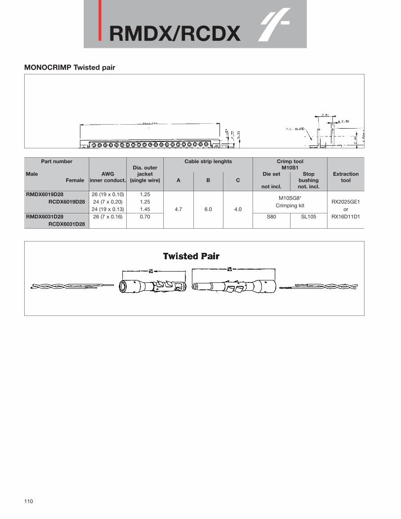
110
RMDX/RCDXMONOCRIMP Twisted pair
Part number Cable strip lenghts Crimp toolDia. outer M10S1
Male AWG jacket Die set Stop ExtractionFemale inner conduct. (single wire) A B C bushing tool
not incl. not. incl.RMDX6019D28 26 (19 x 0.10) 1.25
RCDX6019D28 24 (7 x 0.20) 1.25M10SG8*
RX2025GE124 (19 x 0.13) 1.45 4.7 6.0 4.0
Crimping kitor
RMDX6031D28 26 (7 x 0.16) 0.70 S80 SL105 RX16D11D1RCDX6031D28

111
RMDX/RCDXMONOCRIMP Subminiature coax
Part number
MaleFemale
AWGinner
conduct.
Cabletype
Coax dimensions
Dmax
E F G A B C Die set
not incl.
stopbushingnot incl.
Coax strip lengths Crimp tool M10S1
Extractiontool
RMDX6050D28 - 2.64 2.11 1.70 0.30 5.1 8.9 S80RCDX6016D28 30
RMDX6050D28 - 2.29 1.63 1.22 4.2 8.5 S87RCDX6016D28
RMDX6032D28 28 - 2.90 2.29 1.91 0.38 11.7 S80RCDX6032D28
RMDX6032D28 RG174/U 2.92 2.24 1.52 0.48 5.1 6.35 S80 SL105 RX2025GE1RCDX6032D28
RMDX6026D28 26 - 3.05 2.44 1.96 0.41 S82 ORRCDX6026D28
RMDX6036D28 RG188A/U 2.79 11.7 S80 RX16D11D1RCDX6036D28
RMDX6036D28 RG316/U 2.72 1.98 1.52 0.51RCDX6036D28
* M10SG8 consists of die set, stop bushing and M10S1 tool
RM
DX
/RC
DX

112
SM/SC-W Stamped contacts
How to order
S26S25
33
(L)(L)
WW
2424
SMSC
Contact type: SM: Male contactSC: Female contact
AWG Size: 20, 24
Type of crimp barrel: Open crimp barrel identical to TRIM TRIO
Packing: No digit: Contacts on strip (qty 3000 per reel) L: Preformed loose piece contacts (qty 100 in plastic bag)
Design variation
Plating indication: See plating table
Size 20 stamped andformed contacts forSEALOK connectors
DescriptionSize 20 SM-W/SC-W .040” (1.0mm)diameter contacts are two piece stripformed crimp snap-in pin and sockets.These contacts consist of a crimp bodymade of high conductive copper alloy, and astainless steel retaining spring featuringretention in the housing cavity and a closedentry socket to prevent probe damage.Contacts accomodate AWG20 throughAWG26 wire and the crimp barrels areidentical to the crimp barrels used on theTRIM TRIO contact thus offering theadvantage of using the same crimp tooling.The contact with its open barrel is standardavailable on strip and packaged with 3000pcs on a reel. This reel packaging combinedwith semi or even full automatic crimptooling provides the added advantage of alower installed cost.Each contact has a break-off sectionfacilitating the use handtooling andindividual crimping.
Features and benefits• Made from high conductive copper alloy
with gold or tin over nickel plate finish.• Two piece construction with dual purpose
spring which serves for contact retentionand protects the body against damage.
• Contacts available on reel (3000 pcs) andin bulk packing (100 pcs)
• Crimp tooling is the same as used onTRIM TRIO contacts.
Performance characteristicsCurrent rating: 5 AmpContact resistance: 15 mΩDielectric withstanding voltage:
1500 V RMS minContact retention in body: 90 N max.Contact engagement force: 5 N max.Contact separation force/ 2 N min.
ConstructionContact body: High conductive copper alloy.Outer spring: Stainless steel
Plating table
S25/26 = 0.75µ Gold min. in contact area,gold flash on crimp barrel overNickel.
TK6 = Preplated Tin all over.
Connector accommodation Any SEALOK SM-W / SC-W contact can beused in any contact position in anyconnector in the SEALOK interconnectionsystem.• UTGW Sealok

113
SM/SC-W Stamped contacts
Standard SM-W/SC-W crimp contacts: Contact size 20 - Pin diameter 1.0mm (.040”)
Part number: contacts on stripPart number: Loose piecesmn Wire size
Insulation WirePin contacts Fig. Socket contacts Fig. AWG mm2 diameter strip length
SM24W3S26 2 SC24W3S25 1 26 - 24 0.13 - 0.25 0.89 - 1.58 4.0SM24WL3S26 SC24WL3S25SM20W3S26 2 SC20W3S25 1 22 - 20 0.35 - 0.50 1.17 - 2.08 4.0SM20WL3S26 SC20WL3S25
Dimensional table
Hand crimp tooling for loose contacts
UTM-2 ExtractionSize tooling
Hand tools M8ND Crimpdie set included Die set Mechanism
(not included)
Crimptooling table
For other platings: See plating table
24 Y14MTV (ratchet) N24RT14 CM11G1 RX20D4420 N20RT33
For detailed information on crimp tooling : See crimp tooling section.* without locator S
M/S
C-W

114
Fibre optic contacts
Size 16 Fibre opticcontacts for TRIM TRIO connectors
DescriptionSize 16 (1.6mm) Fibre optic contacts series8012 are optical contacts designed for theintegration of optical links in all TRIM TRIOcable connectors.The F.O. contacts are designed toaccomodate 1000µ plastic fibres with acable diameter of 2.2 mm.
Features and benefits• Socket contact is spring loaded to avoid
any air gap between the two optical faces.• Low insertion loss is provided by high
precision pieces.• Single jumpers, multiway harness and
active device housings can be suppliedaccording customer requirement.
Performance characteristicsfor plastic fibre (depends onsupplier)Temperatur range: -20°C to + 70°CAttenuation at 0.660 µm (at +20°C): < 200 db/Km Min radius: 25 mm Tensile strength 5 daNWeight: 5 daN/KmCable retention: 25 NTypical insertion loss 1.5 dB at 650 nm
ConstructionContact body: Arcap (rustproof)Outer spring: Stainless steel
Connector accommodation Fibre optic contacts can be used in anycontact position in any connector in theTRIM TRIO interconnection system.• MS-M Rectangular connectors• SMS Qikmate• PI43 Eurorack connectors• UT-Bantam• UTG Metalok bantam• UTP Full plastic bantam• UTGS Shielded bantam
How to order
ContactsMale contact: 8012P14J262Female contact: 8012S14J262
For other fibres consult factory.
Tool kitCrimping / polishing technic
The tool kit contains all necessary tools toterminate contacts for plastic fibre, such as• Stripping plier• Crimping plier• Polishing plate and tool• Miscallaneous
Part number tool kit: 80MS0004
Separate tools• Cutting tool 80WD0005• Stripping plier 80WD0025• Crimping plier 80WS0002• Polishing plate 80WP0005• Polishing tool 80WP0018• 10 polishing discks 30 µm 80WP0019• 10 polishing discks 9 µm 80WP0014• Extraction tool RX2025GE1

115
AccessoriesDiscrimination keys forTRIM TRIO connectors
DescriptionIn applications where similar connectors areused next to each other, mismatching canbe a reason for disturbances, system failureor even danger to operating personnel.To eliminate mismatching, all TRIM TRIOconnectors can be equipped withdiscrimination keys, which offer unlimitedpossibilities for a “fool - proof”interconnection system.
When one of these discrimination keys isused, the TRIM TRIO connector will onlymate with a connector which has a vacantcontact or discrimination cavity at thecorresponding position.
This system offers boundless opportunitiesfor all applications which involve severalidentical TRIM TRIO connectors.
The material used is polyamide 6.6
SMSPKB1-5PKA dummy contact, which can be inserted into an empty contact cavity in any of the TRIM TRIO connectors.
SMSPKB2A tube, which can be fitted over a preassembled male contact in all TRIM TRIO male boardmount connectors MSO, SMS, PI43.
AC
CE
SS
OR
IES
- T
OO
LIN
G

116
Accessories
SMSPKE2V1A pin, which can be inserted into a preassambled female contact in all TRIM TRIO female boardmount connectors MSO, SMS, PI43.
SMSPKE3A pin, Which can be inserted in the discrimination cavities of the SMS Qikmate cable and boardmount connectors. The discrimination cavitiesare in between of the contact cavities and offer the advantage that no contact cavities are lost due to discrimination.As extraction tool, the RX2025GE1 without the “extraction tool tip” can be used.To unlock the discrimination pin, insert the extraction tool in the discrimination cavity at the rear side of the connector. Meanwhile, the pin canbe extracted manually at the mating side.

117
Tooling - intro
Overview TRIM TRIO and SEALOK tooling
Selection matrix TRIM TRIO and SEALOK tooling
AC
CE
SS
OR
IES
-TO
OLI
NG

118
Weight: 425 gr.Length: 250 mm.
Weight: 800 gr.Length: 275 mm.
M10S1 - for machined contactsA robust, versatile, full cycling handtool which is fully qualified to therequirements of MIL-C-22520. Interchangeable 4-indent die sets areavailable for a wide range of machined contacts and gives asimultaneous crimp on both wire and insulation.This tool is suitable for application of RM/RC machined contactsand coaxial from the TRIM TRIO range.
M8ND - for machined and formed contactsA robust full cycling hand ratchet tool which utilises interchangeable“N” die sets to crimp Size 16 TRIM TRIO RM/RC loose piece machined contacts. Size 16 TRIM TRIO SM-M/SC-M loose piece formed contacts.Size 20 SEALOK SM-W/SC-W loose piece formed contacts.
Crimptooling
Weight: 400 gr.Length: 230 mm.
Y14MTV - for formed contactA light weight crimptool with fixed 3-groove die set for AWG26 to 14for:Size 16 TRIM TRIO SM-M/SC-M loose piece formed contacts.Size 20 SEALOK SM-W/SC-W loose piece formed contacts.Ratchet controlled to guarantee a complete crimp cycle.

119
AC
CE
SS
OR
IES
- T
OO
LIN
G
Trim Trio + SealokExtraction tooling
RX2025GE1A spring loaded extraction tool for the full range of TRIM TRIO contacts.This tool ensures that the contact locking louvres are fully retracted before anypressure is applied to extract a contact. It is especially suitable for applicationswhere the integrity of the assemblies are of the utmost importance.
RX16D11D1For use with all TRIM TRIO contacts. Must be used with Qikmate rectangularconnectors.
RX20D44A spring loaded extraction tool for the full range of SEALOK contacts.This tool ensures that the contact locking louvres are fully retracted before anypressure is applied to extract a contact. It is especially suitable for applicationswhere the integrity of the assemblies are of the utmost importance.
How to extract a contact out of its cavity? Slide the extraction tip over contact from mating side till the locking springfrom the contact is depressed. Push on handle to push out the contact with the spring loaded inner plunger.
Insertion tooling
RTM205This tool is especially designed to ease insertion of any TRIM TRIO andSEALOK contact crimped on very flexible or small wire sizes. Simply positionthe insertion tool so that the tip of the tool bears against the back of the wirebarrel, retaining the wire with thumb in the groove of the tool.Push the contact slowly into the connector until it snaps into position.

120
Notes
...............................................................................................................................................................................................................
...............................................................................................................................................................................................................
...............................................................................................................................................................................................................
...............................................................................................................................................................................................................
...............................................................................................................................................................................................................
...............................................................................................................................................................................................................
...............................................................................................................................................................................................................
...............................................................................................................................................................................................................
...............................................................................................................................................................................................................
...............................................................................................................................................................................................................
...............................................................................................................................................................................................................
...............................................................................................................................................................................................................
...............................................................................................................................................................................................................
...............................................................................................................................................................................................................
...............................................................................................................................................................................................................
...............................................................................................................................................................................................................
...............................................................................................................................................................................................................
...............................................................................................................................................................................................................
...............................................................................................................................................................................................................
...............................................................................................................................................................................................................
...............................................................................................................................................................................................................
...............................................................................................................................................................................................................
...............................................................................................................................................................................................................
...............................................................................................................................................................................................................
...............................................................................................................................................................................................................
...............................................................................................................................................................................................................
...............................................................................................................................................................................................................
...............................................................................................................................................................................................................
...............................................................................................................................................................................................................
...............................................................................................................................................................................................................
Trim Trio + Sealok

121
Trim Trio + Sealok
Notes
...............................................................................................................................................................................................................
...............................................................................................................................................................................................................
...............................................................................................................................................................................................................
...............................................................................................................................................................................................................
...............................................................................................................................................................................................................
...............................................................................................................................................................................................................
...............................................................................................................................................................................................................
...............................................................................................................................................................................................................
...............................................................................................................................................................................................................
...............................................................................................................................................................................................................
...............................................................................................................................................................................................................
...............................................................................................................................................................................................................
...............................................................................................................................................................................................................
...............................................................................................................................................................................................................
...............................................................................................................................................................................................................
...............................................................................................................................................................................................................
...............................................................................................................................................................................................................
...............................................................................................................................................................................................................
...............................................................................................................................................................................................................
...............................................................................................................................................................................................................
...............................................................................................................................................................................................................
...............................................................................................................................................................................................................
...............................................................................................................................................................................................................
...............................................................................................................................................................................................................
...............................................................................................................................................................................................................
...............................................................................................................................................................................................................
...............................................................................................................................................................................................................
...............................................................................................................................................................................................................
...............................................................................................................................................................................................................
...............................................................................................................................................................................................................

122
Trim Trio + Sealok
Notes
...............................................................................................................................................................................................................
...............................................................................................................................................................................................................
...............................................................................................................................................................................................................
...............................................................................................................................................................................................................
...............................................................................................................................................................................................................
...............................................................................................................................................................................................................
...............................................................................................................................................................................................................
...............................................................................................................................................................................................................
...............................................................................................................................................................................................................
...............................................................................................................................................................................................................
...............................................................................................................................................................................................................
...............................................................................................................................................................................................................
...............................................................................................................................................................................................................
...............................................................................................................................................................................................................
...............................................................................................................................................................................................................
...............................................................................................................................................................................................................
...............................................................................................................................................................................................................
...............................................................................................................................................................................................................
...............................................................................................................................................................................................................
...............................................................................................................................................................................................................
...............................................................................................................................................................................................................
...............................................................................................................................................................................................................
...............................................................................................................................................................................................................
...............................................................................................................................................................................................................
...............................................................................................................................................................................................................
...............................................................................................................................................................................................................
...............................................................................................................................................................................................................
...............................................................................................................................................................................................................
...............................................................................................................................................................................................................
...............................................................................................................................................................................................................

123
Trim Trio + Sealok
Notes
...............................................................................................................................................................................................................
...............................................................................................................................................................................................................
...............................................................................................................................................................................................................
...............................................................................................................................................................................................................
...............................................................................................................................................................................................................
...............................................................................................................................................................................................................
...............................................................................................................................................................................................................
...............................................................................................................................................................................................................
...............................................................................................................................................................................................................
...............................................................................................................................................................................................................
...............................................................................................................................................................................................................
...............................................................................................................................................................................................................
...............................................................................................................................................................................................................
...............................................................................................................................................................................................................
...............................................................................................................................................................................................................
...............................................................................................................................................................................................................
...............................................................................................................................................................................................................
...............................................................................................................................................................................................................
...............................................................................................................................................................................................................
...............................................................................................................................................................................................................
...............................................................................................................................................................................................................
...............................................................................................................................................................................................................
...............................................................................................................................................................................................................
...............................................................................................................................................................................................................
...............................................................................................................................................................................................................
...............................................................................................................................................................................................................
...............................................................................................................................................................................................................
...............................................................................................................................................................................................................
...............................................................................................................................................................................................................
...............................................................................................................................................................................................................

124
Notes
...............................................................................................................................................................................................................
...............................................................................................................................................................................................................
...............................................................................................................................................................................................................
...............................................................................................................................................................................................................
...............................................................................................................................................................................................................
...............................................................................................................................................................................................................
...............................................................................................................................................................................................................
...............................................................................................................................................................................................................
...............................................................................................................................................................................................................
...............................................................................................................................................................................................................
...............................................................................................................................................................................................................
...............................................................................................................................................................................................................
...............................................................................................................................................................................................................
...............................................................................................................................................................................................................
...............................................................................................................................................................................................................
...............................................................................................................................................................................................................
...............................................................................................................................................................................................................
...............................................................................................................................................................................................................
...............................................................................................................................................................................................................
...............................................................................................................................................................................................................
...............................................................................................................................................................................................................
...............................................................................................................................................................................................................
...............................................................................................................................................................................................................
...............................................................................................................................................................................................................
...............................................................................................................................................................................................................
...............................................................................................................................................................................................................
...............................................................................................................................................................................................................
...............................................................................................................................................................................................................
...............................................................................................................................................................................................................
...............................................................................................................................................................................................................
Trim Trio + Sealok

125
Notes
...............................................................................................................................................................................................................
...............................................................................................................................................................................................................
...............................................................................................................................................................................................................
...............................................................................................................................................................................................................
...............................................................................................................................................................................................................
...............................................................................................................................................................................................................
...............................................................................................................................................................................................................
...............................................................................................................................................................................................................
...............................................................................................................................................................................................................
...............................................................................................................................................................................................................
...............................................................................................................................................................................................................
...............................................................................................................................................................................................................
...............................................................................................................................................................................................................
...............................................................................................................................................................................................................
...............................................................................................................................................................................................................
...............................................................................................................................................................................................................
...............................................................................................................................................................................................................
...............................................................................................................................................................................................................
...............................................................................................................................................................................................................
...............................................................................................................................................................................................................
...............................................................................................................................................................................................................
...............................................................................................................................................................................................................
...............................................................................................................................................................................................................
...............................................................................................................................................................................................................
...............................................................................................................................................................................................................
...............................................................................................................................................................................................................
...............................................................................................................................................................................................................
...............................................................................................................................................................................................................
...............................................................................................................................................................................................................
...............................................................................................................................................................................................................
Trim Trio + Sealok

126
Notes
...............................................................................................................................................................................................................
...............................................................................................................................................................................................................
...............................................................................................................................................................................................................
...............................................................................................................................................................................................................
...............................................................................................................................................................................................................
...............................................................................................................................................................................................................
...............................................................................................................................................................................................................
...............................................................................................................................................................................................................
...............................................................................................................................................................................................................
...............................................................................................................................................................................................................
...............................................................................................................................................................................................................
...............................................................................................................................................................................................................
...............................................................................................................................................................................................................
...............................................................................................................................................................................................................
...............................................................................................................................................................................................................
...............................................................................................................................................................................................................
...............................................................................................................................................................................................................
...............................................................................................................................................................................................................
...............................................................................................................................................................................................................
...............................................................................................................................................................................................................
...............................................................................................................................................................................................................
...............................................................................................................................................................................................................
...............................................................................................................................................................................................................
...............................................................................................................................................................................................................
...............................................................................................................................................................................................................
...............................................................................................................................................................................................................
...............................................................................................................................................................................................................
...............................................................................................................................................................................................................
...............................................................................................................................................................................................................
...............................................................................................................................................................................................................
Trim Trio + Sealok

http://www.fciconnect.com
© C
opyr
ight
Fra
mat
ome
Con
nect
ors
Inte
rnat
iona
l, S
.A. A
ll rig
hts
rese
rved
.U
SA
(E
) C
hip
C 0
798
US
950563-001 9/01
U.S.A. Tel.: (800) 237-2374; 717-938-7200Canada Tel.: 905-826-9810
Europe Tel.: 33-1-39-49-21-83Asia/Pacific Tel.: 65-549-6666