Trike Conversion Installation Guide Victory Cross Roads ... · Trike Conversion Installation Guide...
22
VICTORY TRIKE CONVERSION CHAMPION TRIKES Installation Guide – Victory Cross Country Tour 2013 Page 1 of 22 05/06/2013 Kurt Larson and Jan Myburgh Trike Conversion Installation Guide Victory Cross Roads Classic and 8-Ball Victory Cross Country/Tour/8-Ball and Ness Cross Country Limited-Edition 2013 and Up Independent Suspension Rev. 1 CAUTION: -Failure to make the proper adjustments will potentially lead to serious personal injury and/or property damage and may void the warranty. -Champion does not guarantee fit form or function to any of their trike kits if altered or aftermarket components were added to the original bike design. -All dealers or installers should make proper adjustments with the customer before delivery. Champion is not responsible for additional adjustments made under warranty. Champion Motorcycle Accessories International, Inc. dba Champion Sidecars 11841 Monarch Street, CA 92841 (800) 875-0949 (714) 847-0949 Fax (714) 847-1539 www.championtrikes.com
Transcript of Trike Conversion Installation Guide Victory Cross Roads ... · Trike Conversion Installation Guide...

VICTORY TRIKE CONVERSION
CHAMPION TRIKES
Installation Guide – Victory Cross Country Tour 2013
Page 1 of 22 05/06/2013
Kurt Larson and Jan Myburgh
Trike Conversion Installation Guide
Victory Cross Roads Classic and 8-Ball Victory Cross Country/Tour/8-Ball and Ness Cross
Country Limited-Edition 2013 and Up
Independent Suspension Rev. 1
CAUTION: -Failure to make the proper adjustments will potentially lead to serious personal injury and/or property damage and may void the warranty. -Champion does not guarantee fit form or function to any of their trike kits if altered or aftermarket components were added to the original bike design. -All dealers or installers should make proper adjustments with the customer before delivery. Champion is not responsible for additional adjustments made under warranty.
Champion Motorcycle Accessories International, Inc.
dba Champion Sidecars
11841 Monarch Street, CA 92841 (800) 875-0949 (714) 847-0949 Fax (714) 847-1539
www.championtrikes.com

VICTORY TRIKE CONVERSION
CHAMPION TRIKES
Installation Guide – Victory Cross Country Tour 2013
Page 2 of 22 05/06/2013
Kurt Larson and Jan Myburgh
Table of Contents
1 General Information .............................................................................................................................................3 1.1 Installation Information ................................................................................................................................3
a. Altered or Changed from OEM Warning .....................................................................................................3 1.2 For Your Safety ...........................................................................................................................................3 1.3 Important Safety Precautions .....................................................................................................................3 1.4 Specifications ..............................................................................................................................................4 1.5 Part Description ..........................................................................................................................................4
2 Removal of Original Parts ...................................................................................................................................5 3 Installing Trike Conversion Kit .............................................................................................................................6
3.1 Install OEM Belt ..........................................................................................................................................6 3.2 Install Top Frame ........................................................................................................................................6 3.3 Install Rear End Assembly..........................................................................................................................8 3.4 Install Swing Arm and Body Frame ............................................................................................................9 3.5 Align and Tension Drive Belt ................................................................................................................... 11 3.6 Install Anti-Roll Bar .................................................................................................................................. 12
a. Standard Anti-Roll Bar ............................................................................................................................. 12 b. Variable Sway Control (VSC) Optional .................................................................................................... 13
3.7 Install Brake Parts .................................................................................................................................... 13 3.8 Install Exhaust Parts ................................................................................................................................ 15 3.9 Cross Country Body and Side Panel Installation ..................................................................................... 16 3.10 Tour Box installation ................................................................................................................................ 17 3.11 Exhaust Cover Installation ....................................................................................................................... 17 3.12 Wheel and Tire Installation ...................................................................................................................... 21 3.13 Antenna Replacement ............................................................................................................................. 21 3.14 Install Trailer Hitch Receiver (Optional) ................................................................................................... 21
4 Shock Adjustment ............................................................................................................................................ 22 4.1 Adjusting Shock Preload.......................................................................................................................... 22
VICTORY TRIKE CONVERSION
CHAMPION TRIKES
Installation Guide – Victory Cross Country Tour 2013
Page 3 of 22 05/06/2013
Kurt Larson and Jan Myburgh
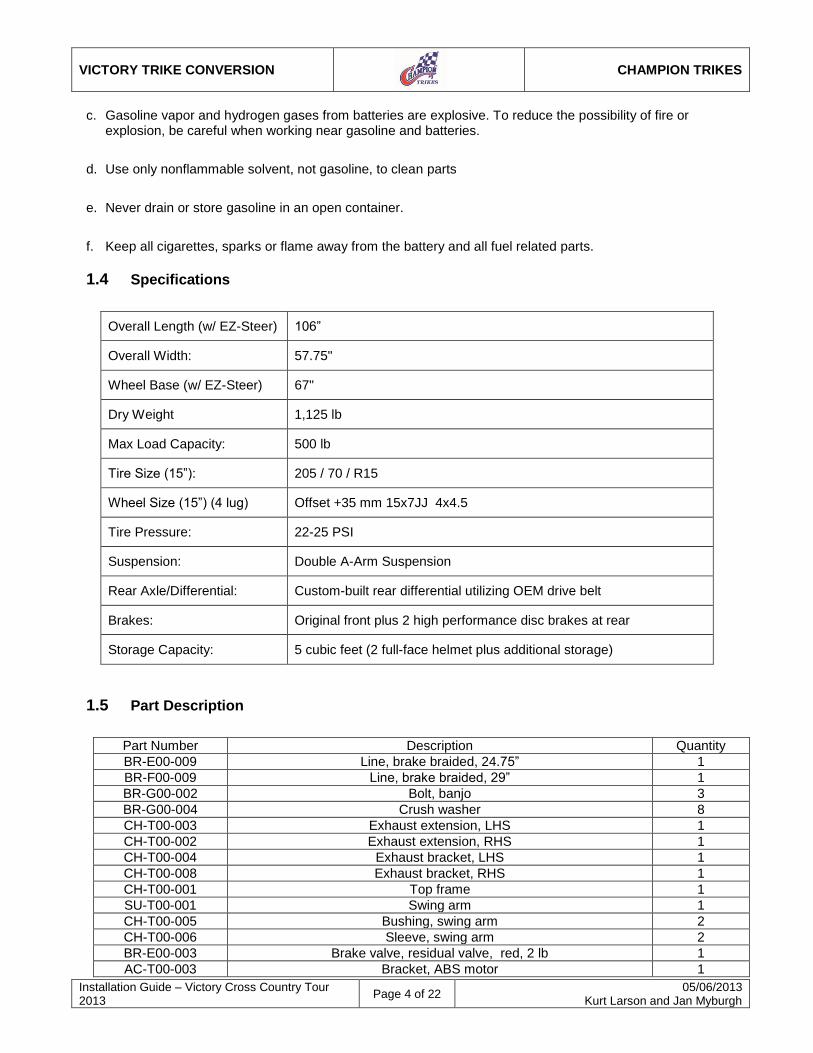
1 General Information
The Champion Trike Conversion Kit is designed with the utmost consideration for safety, quality and ease of installation. The kit comes complete with all necessary hardware and fasteners. It is recommended that the installer obtain an OEM service manual for the vehicle on which the Trike kit is to be installed. Please review the installation instructions before installing the kit.
1.1 Installation Information
The information contained in this installation guide is intended for use by technicians of advanced to professional skill levels. Attempting installation without the proper training, tools and equipment may result in damage to the vehicle, cause unsafe conditions, or cause personal injury to you and/or others. a. Altered or Changed from OEM Warning
CAUTION: Champion trike kits are designed for installation on unmodified motorcycles as from the OEM. Champion does not guarantee fit, form, or function, on any of their trike kits if installed with altered or aftermarket parts differing from the original bike design.
1.2 For Your Safety
Because this guide is intended for technicians of advanced to professional skill levels, we do not provide warnings about many basic shop safety practices. If you have not received shop safety training or do not feel confident about your knowledge of safety practices, we recommend that you do not attempt to perform the procedures described in this guide.
Some of the most important general safety precautions are given below. Champion Trikes cannot warn you of every conceivable hazard that can arise. Only you can decide whether or not you should perform a given task.
1.3 Important Safety Precautions
a. Make sure you have a clear understanding of all basic shop safety practices and that you wear appropriate clothing and use safety equipment. Be especially careful of the following:
Read all directions before you begin, and make sure you have the tools, the parts and the skills required to perform the tasks safely and completely.
Protect your eyes by using proper safety glasses, goggles or face shields anytime you hammer, drill, grind, pry or work around pressurized air or liquids, and springs or other stored-energy components.
Use other protective wear when necessary, for example gloves or safety shoes. Handling hot or sharp parts can cause severe burns or cuts.
Protect yourself and others when you have a vehicle up in the air. Anytime you lift a vehicle, either by hoist or a jack, make sure that it is securely supported.
b. Make sure the engine is turned off before you begin work.
Carbon Monoxide poisoning from exhaust gases: Be sure there is adequate ventilation whenever you run the engine.
Burns from hot parts: Let the engine and exhaust system cool before working on those areas.
Injury from moving parts: If running the engine, keep hands, fingers and clothing away from moving/rotating parts.
VICTORY TRIKE CONVERSION
CHAMPION TRIKES
Installation Guide – Victory Cross Country Tour 2013
Page 4 of 22 05/06/2013
Kurt Larson and Jan Myburgh
c. Gasoline vapor and hydrogen gases from batteries are explosive. To reduce the possibility of fire or explosion, be careful when working near gasoline and batteries.
d. Use only nonflammable solvent, not gasoline, to clean parts
e. Never drain or store gasoline in an open container.
f. Keep all cigarettes, sparks or flame away from the battery and all fuel related parts.
1.4 Specifications
Overall Length (w/ EZ-Steer) 106”
Overall Width: 57.75"
Wheel Base (w/ EZ-Steer) 67"
Dry Weight 1,125 lb
Max Load Capacity: 500 lb
Tire Size (15”): 205 / 70 / R15
Wheel Size (15”) (4 lug) Offset +35 mm 15x7JJ 4x4.5
Tire Pressure: 22-25 PSI
Suspension: Double A-Arm Suspension
Rear Axle/Differential: Custom-built rear differential utilizing OEM drive belt
Brakes: Original front plus 2 high performance disc brakes at rear
Storage Capacity: 5 cubic feet (2 full-face helmet plus additional storage)
1.5 Part Description
Part Number Description Quantity
BR-E00-009 Line, brake braided, 24.75” 1
BR-F00-009 Line, brake braided, 29” 1
BR-G00-002 Bolt, banjo 3
BR-G00-004 Crush washer 8
CH-T00-003 Exhaust extension, LHS 1
CH-T00-002 Exhaust extension, RHS 1
CH-T00-004 Exhaust bracket, LHS 1
CH-T00-008 Exhaust bracket, RHS 1
CH-T00-001 Top frame 1
SU-T00-001 Swing arm 1
CH-T00-005 Bushing, swing arm 2
CH-T00-006 Sleeve, swing arm 2
BR-E00-003 Brake valve, residual valve, red, 2 lb 1
AC-T00-003 Bracket, ABS motor 1
VICTORY TRIKE CONVERSION
CHAMPION TRIKES
Installation Guide – Victory Cross Country Tour 2013
Page 5 of 22 05/06/2013
Kurt Larson and Jan Myburgh
HWK-T00-001 Hardware kit 1
2 Removal of Original Parts
Champion does not change components that will affect or change the emission characteristics of the motorcycle. - Secure and raise motorcycle at least 10 inches. - Remove the following from the vehicle for installation. See OEM manual for detailed instructions.
Disconnect battery leads
Seat (both front and rear)
Top Box (if equipped)
Saddle Bags
Mufflers (and chrome covers over muffler joints if needed)
Saddlebag Rails (if so equipped)
Top Box Frame and Chrome Covers (if equipped)
Side Body Panels
Rear Wheel
Rear Caliper
NOTE: Prior to disconnecting the line at the caliper, depress the foot brake and secure it in the down position (zip-tie to floor board). This will prevent fluid flow when the rear brake caliper is removed.
Rear Brake Line (disconnect line at master cylinder)
Rear Fender (Remove the passenger seat catch with bolts from the fender)
a. Swing Arm
b. Remove Shock Linkage from Swing Arm
c. Rear Shock
- Indentify and label OEM hardware. OEM hardware will be reused for this conversion and is referenced in the following instructions.
VICTORY TRIKE CONVERSION
CHAMPION TRIKES
Installation Guide – Victory Cross Country Tour 2013
Page 6 of 22 05/06/2013
Kurt Larson and Jan Myburgh
3 Installing Trike Conversion Kit
3.1 Install OEM Belt
a. Reuse factory belt and install it onto front countershaft sprocket as per the OEM service manual.
3.2 Install Top Frame
a. Bolt OEM purge tank with bracket to top frame assembly reusing the factory bolts.
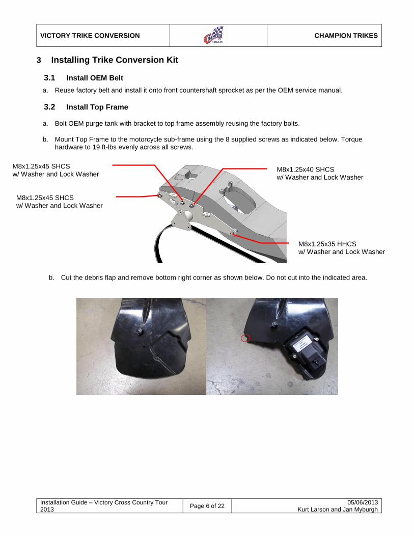
b. Mount Top Frame to the motorcycle sub-frame using the 8 supplied screws as indicated below. Torque hardware to 19 ft-lbs evenly across all screws.
b. Cut the debris flap and remove bottom right corner as shown below. Do not cut into the indicated area.
M8x1.25x35 HHCS w/ Washer and Lock Washer
M8x1.25x40 SHCS w/ Washer and Lock Washer
M8x1.25x45 SHCS w/ Washer and Lock Washer
M8x1.25x45 SHCS w/ Washer and Lock Washer
VICTORY TRIKE CONVERSION
CHAMPION TRIKES
Installation Guide – Victory Cross Country Tour 2013
Page 7 of 22 05/06/2013
Kurt Larson and Jan Myburgh
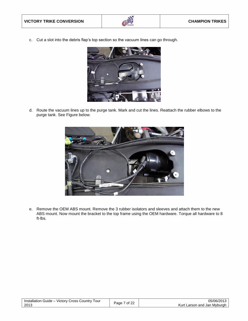
c. Cut a slot into the debris flap’s top section so the vacuum lines can go through.
d. Route the vacuum lines up to the purge tank. Mark and cut the lines. Reattach the rubber elbows to the purge tank. See Figure below.
e. Remove the OEM ABS mount. Remove the 3 rubber isolators and sleeves and attach them to the new ABS mount. Now mount the bracket to the top frame using the OEM hardware. Torque all hardware to 8 ft-lbs.
VICTORY TRIKE CONVERSION
CHAMPION TRIKES
Installation Guide – Victory Cross Country Tour 2013
Page 8 of 22 05/06/2013
Kurt Larson and Jan Myburgh
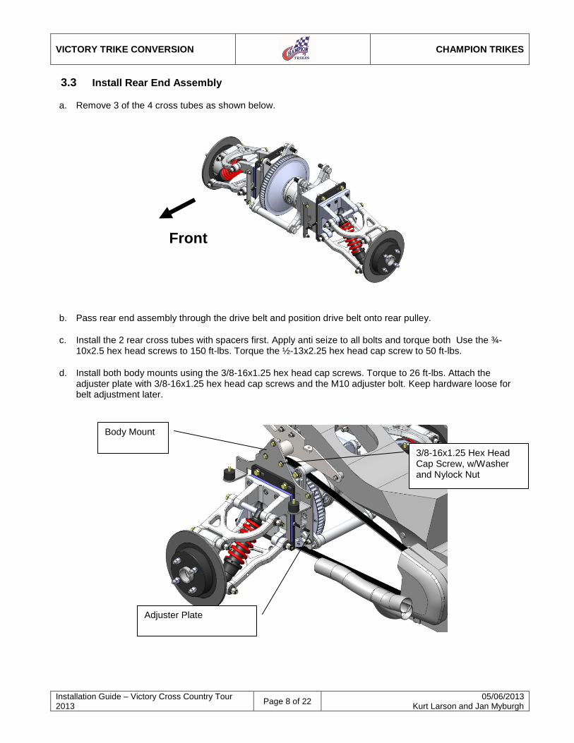
3.3 Install Rear End Assembly
a. Remove 3 of the 4 cross tubes as shown below.
b. Pass rear end assembly through the drive belt and position drive belt onto rear pulley.
c. Install the 2 rear cross tubes with spacers first. Apply anti seize to all bolts and torque both Use the ¾-10x2.5 hex head screws to 150 ft-lbs. Torque the ½-13x2.25 hex head cap screw to 50 ft-lbs.
d. Install both body mounts using the 3/8-16x1.25 hex head cap screws. Torque to 26 ft-lbs. Attach the adjuster plate with 3/8-16x1.25 hex head cap screws and the M10 adjuster bolt. Keep hardware loose for belt adjustment later.
Front
Body Mount
3/8-16x1.25 Hex Head Cap Screw, w/Washer and Nylock Nut
Adjuster Plate
VICTORY TRIKE CONVERSION
CHAMPION TRIKES
Installation Guide – Victory Cross Country Tour 2013
Page 9 of 22 05/06/2013
Kurt Larson and Jan Myburgh
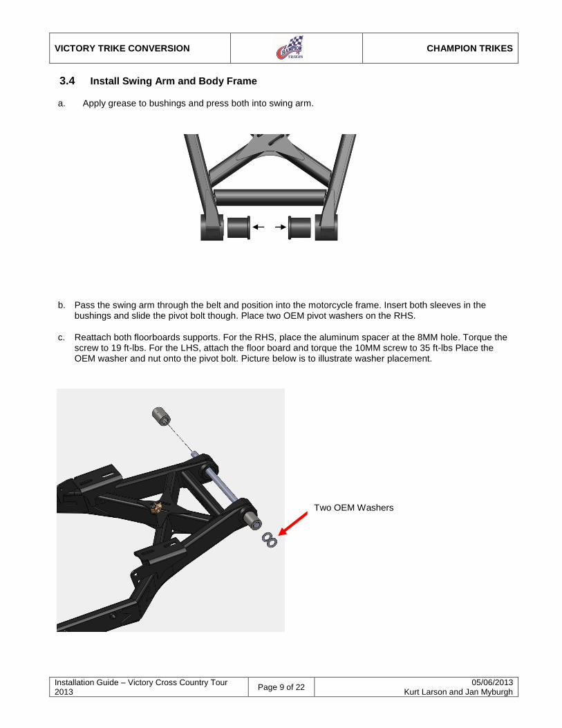
3.4 Install Swing Arm and Body Frame
a. Apply grease to bushings and press both into swing arm.
b. Pass the swing arm through the belt and position into the motorcycle frame. Insert both sleeves in the bushings and slide the pivot bolt though. Place two OEM pivot washers on the RHS.
c. Reattach both floorboards supports. For the RHS, place the aluminum spacer at the 8MM hole. Torque the screw to 19 ft-lbs. For the LHS, attach the floor board and torque the 10MM screw to 35 ft-lbs Place the OEM washer and nut onto the pivot bolt. Picture below is to illustrate washer placement.
Two OEM Washers
VICTORY TRIKE CONVERSION
CHAMPION TRIKES
Installation Guide – Victory Cross Country Tour 2013
Page 10 of 22 05/06/2013
Kurt Larson and Jan Myburgh
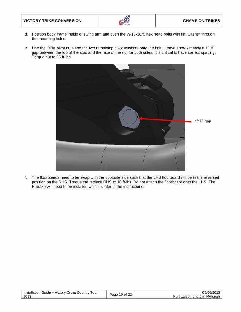
d. Position body frame inside of swing arm and push the ½-13x3.75 hex head bolts with flat washer through the mounting holes.
e. Use the OEM pivot nuts and the two remaining pivot washers onto the bolt. Leave approximately a 1/16” gap between the top of the stud and the face of the nut for both sides. It is critical to have correct spacing. Torque nut to 85 ft-lbs.
f. The floorboards need to be swap with the opposite side such that the LHS floorboard will be in the reversed position on the RHS. Torque the replace RHS to 18 ft-lbs. Do not attach the floorboard onto the LHS. The E-brake will need to be installed which is later in the instructions.
1/16” gap
VICTORY TRIKE CONVERSION
CHAMPION TRIKES
Installation Guide – Victory Cross Country Tour 2013
Page 11 of 22 05/06/2013
Kurt Larson and Jan Myburgh
3.5 Align and Tension Drive Belt
a. Set the belt tension and alignment by moving the independent drive train unit forward or rearward as necessary using the adjuster bolts. Belt tension can be measured by total vertical movement and should be approximately ¾”-1” with a new belt.
Tip: Measure from the bracket to the face of the drive train on each side to get the alignment close. Then perform the next step.
b. To check the alignment, turn the sprocket by hand in the forward direction, noting whether the belt runs in the center of the pulley. If the pulley runs on the right side plate of the pulley, use the right hand adjuster bolts to move the right wheel rearward until the belt runs in the center. If the belt runs on the left side plate of the pulley, use the left adjuster bolts to move the left wheel rearward. Make small adjustments and recheck the alignment.
c. Once the belt is aligned, torque the four front 1/2" fasteners to 70 ft-lbs and double check belt alignment. If alignment is off, please repeat alignment process.
d. Tighten all fasteners left loose for belt adjustment.
Torque the four rear ½” fasteners to 70 ft-lbs.
Torque the Side Body Mount brackets to Top Frame 3/8-24x1.25 HHCS to 45ft-lbs.
Torque the OEM pivot bolt nut to 80 ft-lbs.
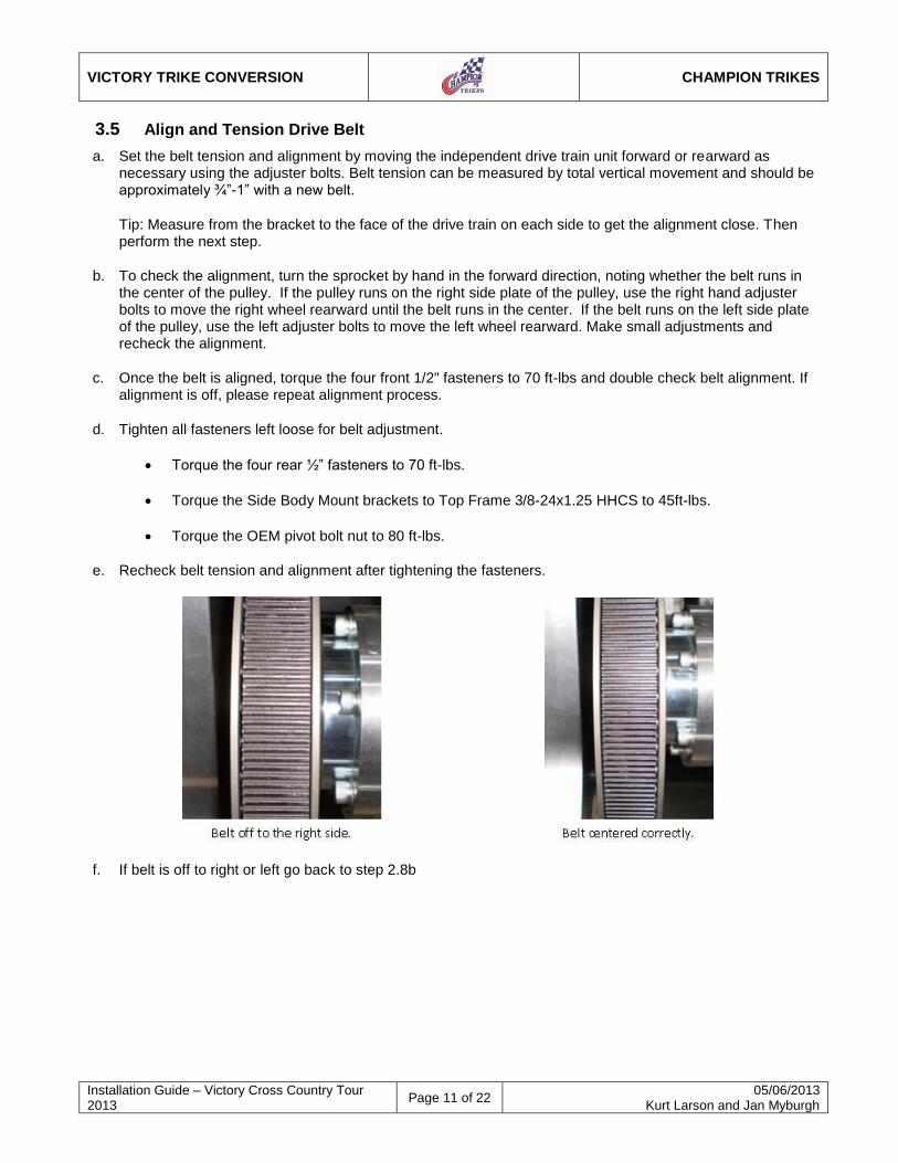
e. Recheck belt tension and alignment after tightening the fasteners.
f. If belt is off to right or left go back to step 2.8b
VICTORY TRIKE CONVERSION
CHAMPION TRIKES
Installation Guide – Victory Cross Country Tour 2013
Page 12 of 22 05/06/2013
Kurt Larson and Jan Myburgh
3.6 Install Anti-Roll Bar
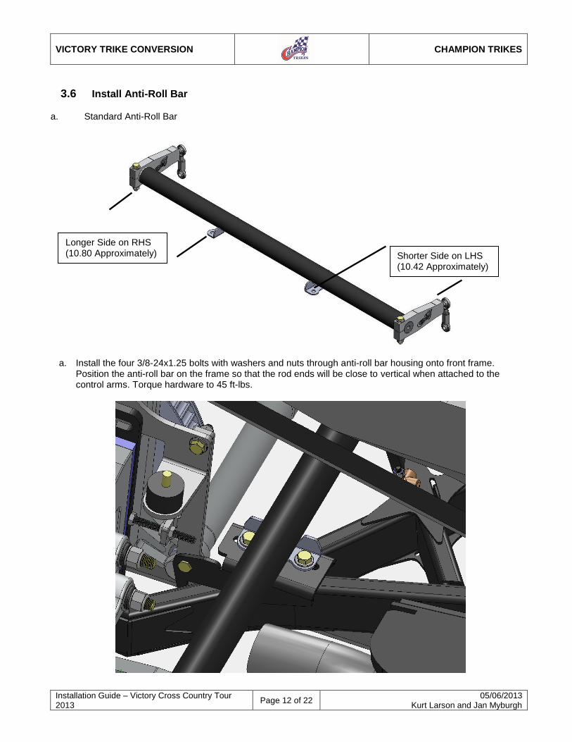
a. Standard Anti-Roll Bar
a. Install the four 3/8-24x1.25 bolts with washers and nuts through anti-roll bar housing onto front frame. Position the anti-roll bar on the frame so that the rod ends will be close to vertical when attached to the control arms. Torque hardware to 45 ft-lbs.
Longer Side on RHS (10.80 Approximately) Shorter Side on LHS
(10.42 Approximately)
VICTORY TRIKE CONVERSION
CHAMPION TRIKES
Installation Guide – Victory Cross Country Tour 2013
Page 13 of 22 05/06/2013
Kurt Larson and Jan Myburgh
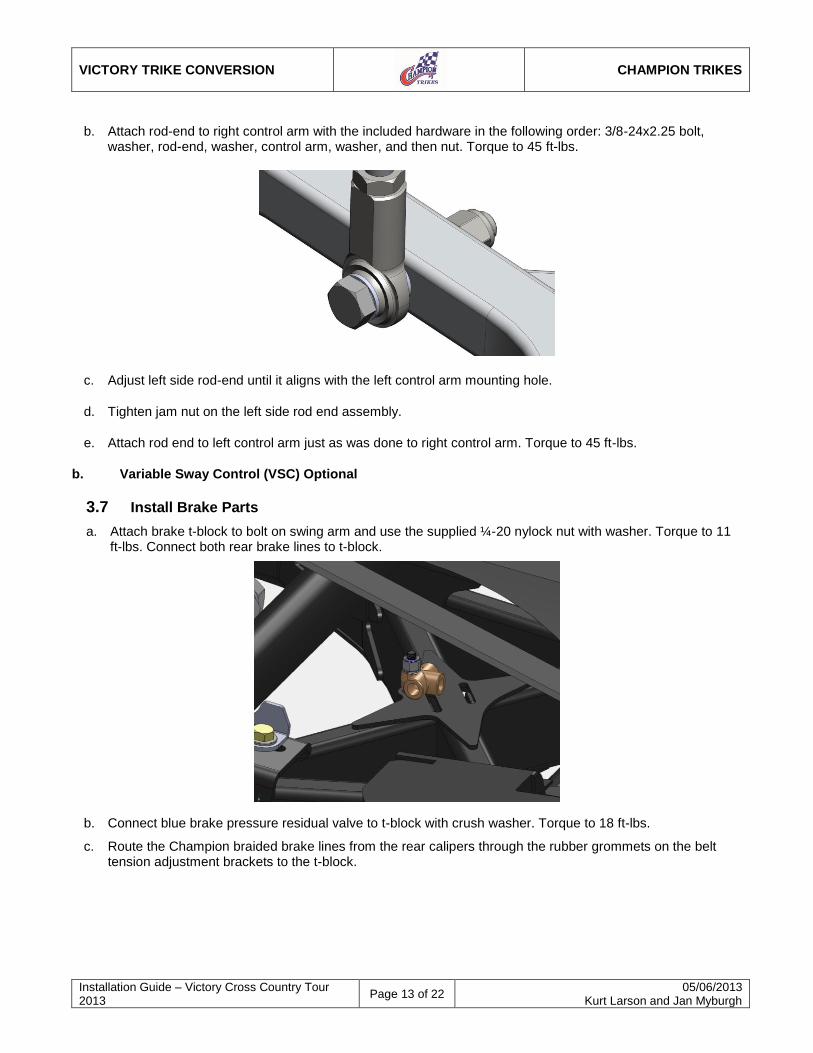
b. Attach rod-end to right control arm with the included hardware in the following order: 3/8-24x2.25 bolt, washer, rod-end, washer, control arm, washer, and then nut. Torque to 45 ft-lbs.
c. Adjust left side rod-end until it aligns with the left control arm mounting hole.
d. Tighten jam nut on the left side rod end assembly.
e. Attach rod end to left control arm just as was done to right control arm. Torque to 45 ft-lbs.
b. Variable Sway Control (VSC) Optional
3.7 Install Brake Parts
a. Attach brake t-block to bolt on swing arm and use the supplied ¼-20 nylock nut with washer. Torque to 11 ft-lbs. Connect both rear brake lines to t-block.
b. Connect blue brake pressure residual valve to t-block with crush washer. Torque to 18 ft-lbs.
c. Route the Champion braided brake lines from the rear calipers through the rubber grommets on the belt tension adjustment brackets to the t-block.
VICTORY TRIKE CONVERSION
CHAMPION TRIKES
Installation Guide – Victory Cross Country Tour 2013
Page 14 of 22 05/06/2013
Kurt Larson and Jan Myburgh
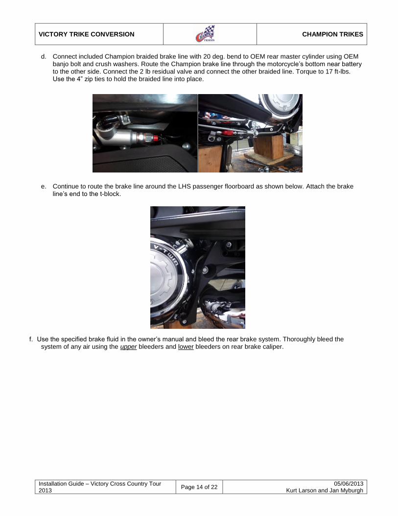
d. Connect included Champion braided brake line with 20 deg. bend to OEM rear master cylinder using OEM banjo bolt and crush washers. Route the Champion brake line through the motorcycle’s bottom near battery to the other side. Connect the 2 lb residual valve and connect the other braided line. Torque to 17 ft-lbs. Use the 4” zip ties to hold the braided line into place.
e. Continue to route the brake line around the LHS passenger floorboard as shown below. Attach the brake
line’s end to the t-block.
f. Use the specified brake fluid in the owner’s manual and bleed the rear brake system. Thoroughly bleed the system of any air using the upper bleeders and lower bleeders on rear brake caliper.
VICTORY TRIKE CONVERSION
CHAMPION TRIKES
Installation Guide – Victory Cross Country Tour 2013
Page 15 of 22 05/06/2013
Kurt Larson and Jan Myburgh
3.8 Install Exhaust Parts
a. Loosen bolts connecting the exhaust to the engine so that the right side exhaust extension is easier to put on.
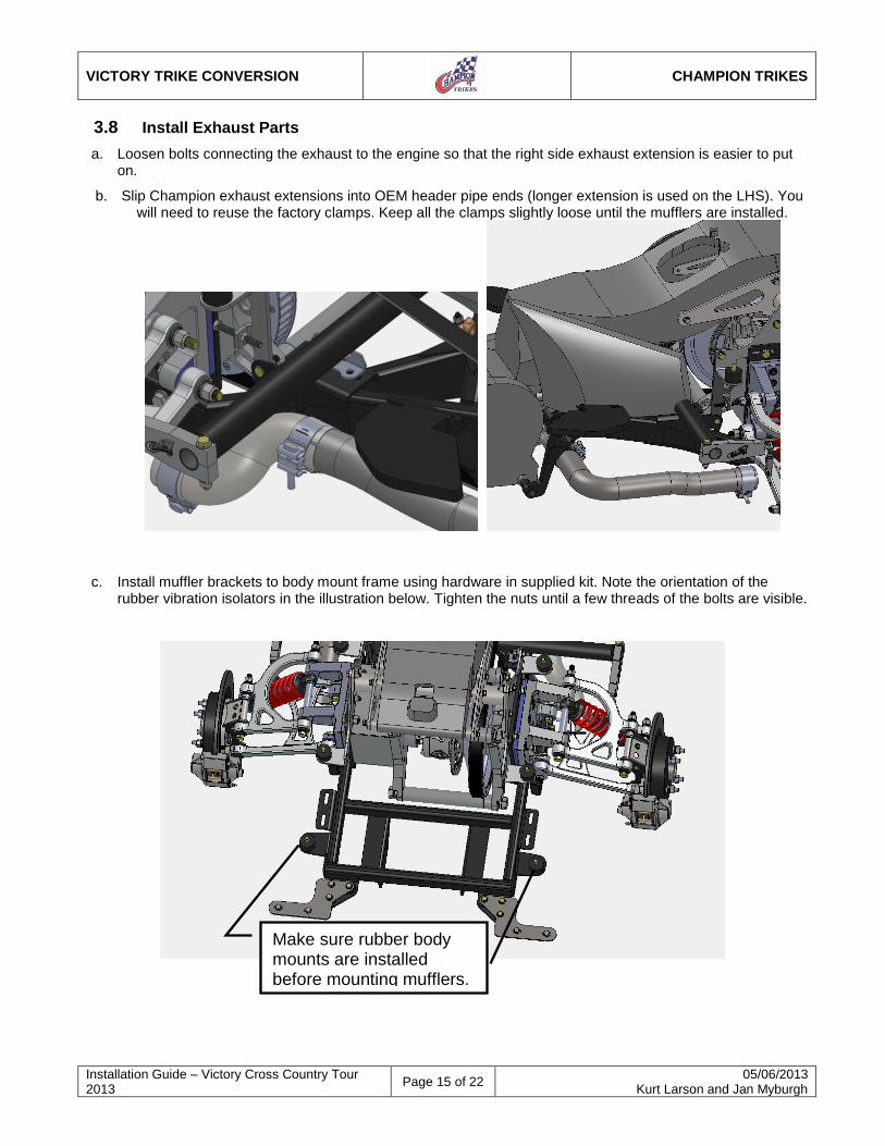
b. Slip Champion exhaust extensions into OEM header pipe ends (longer extension is used on the LHS). You will need to reuse the factory clamps. Keep all the clamps slightly loose until the mufflers are installed.
c. Install muffler brackets to body mount frame using hardware in supplied kit. Note the orientation of the rubber vibration isolators in the illustration below. Tighten the nuts until a few threads of the bolts are visible.
Make sure rubber body mounts are installed before mounting mufflers.
VICTORY TRIKE CONVERSION
CHAMPION TRIKES
Installation Guide – Victory Cross Country Tour 2013
Page 16 of 22 05/06/2013
Kurt Larson and Jan Myburgh
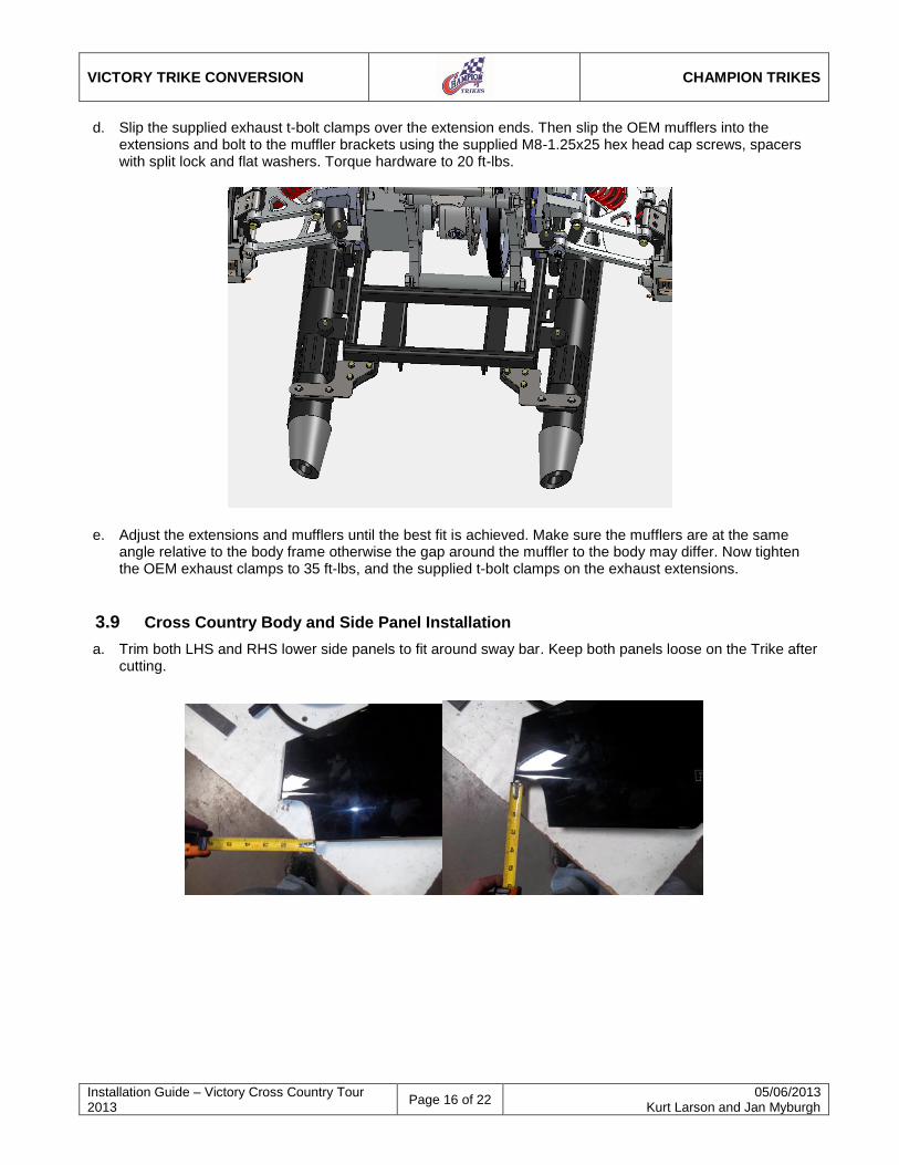
d. Slip the supplied exhaust t-bolt clamps over the extension ends. Then slip the OEM mufflers into the extensions and bolt to the muffler brackets using the supplied M8-1.25x25 hex head cap screws, spacers with split lock and flat washers. Torque hardware to 20 ft-lbs.
e. Adjust the extensions and mufflers until the best fit is achieved. Make sure the mufflers are at the same angle relative to the body frame otherwise the gap around the muffler to the body may differ. Now tighten the OEM exhaust clamps to 35 ft-lbs, and the supplied t-bolt clamps on the exhaust extensions.
3.9 Cross Country Body and Side Panel Installation
a. Trim both LHS and RHS lower side panels to fit around sway bar. Keep both panels loose on the Trike after cutting.
VICTORY TRIKE CONVERSION
CHAMPION TRIKES
Installation Guide – Victory Cross Country Tour 2013
Page 17 of 22 05/06/2013
Kurt Larson and Jan Myburgh
Note: The installation/alignment of the body is an iterative process to find the correct position of body in relation to the wheels. The six holes already in the body are primarily for shipping purposes. These holes may line up with the pre-drilled body frame holes when the body is fitted, but may need to be elongated to align body.
b. Make sure the two rear rubber mounts are attached to the rear frame and are loose.
c. Place trike body, with front four rubber mounts attached, onto all six mounting locations.
d. Install the hardware as it came shipped and keep loose.
e. Position the trike body to best fit both the rear wheels and bike frame.
f. Only drill or slot the two rear holes in the body larger if necessary.
g. Tighten all six 3/8-16 short nylock nuts to 20 ft. lbs.
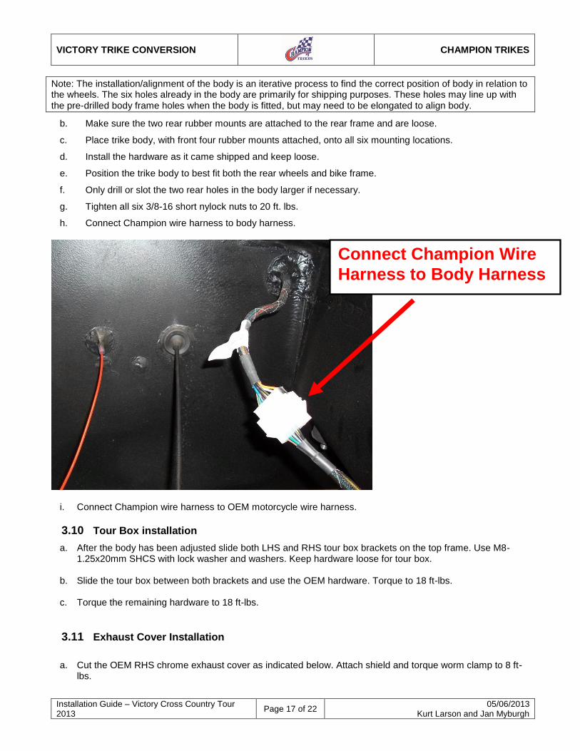
h. Connect Champion wire harness to body harness.
i. Connect Champion wire harness to OEM motorcycle wire harness.
3.10 Tour Box installation
a. After the body has been adjusted slide both LHS and RHS tour box brackets on the top frame. Use M8-1.25x20mm SHCS with lock washer and washers. Keep hardware loose for tour box.
b. Slide the tour box between both brackets and use the OEM hardware. Torque to 18 ft-lbs.
c. Torque the remaining hardware to 18 ft-lbs.
3.11 Exhaust Cover Installation
a. Cut the OEM RHS chrome exhaust cover as indicated below. Attach shield and torque worm clamp to 8 ft-
lbs.
Connect Champion Wire
Harness to Body Harness
VICTORY TRIKE CONVERSION
CHAMPION TRIKES
Installation Guide – Victory Cross Country Tour 2013
Page 18 of 22 05/06/2013
Kurt Larson and Jan Myburgh
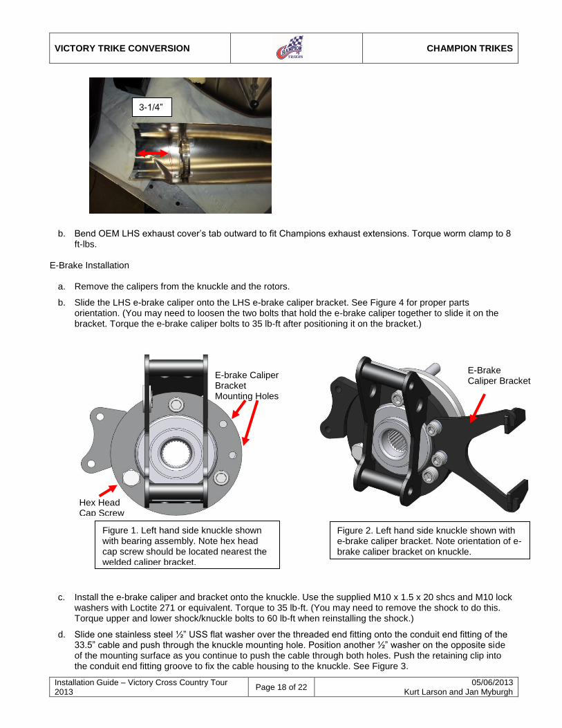
Figure 1. Left hand side knuckle shown with bearing assembly. Note hex head cap screw should be located nearest the welded caliper bracket.
E-brake Caliper Bracket Mounting Holes
Hex Head Cap Screw
Figure 2. Left hand side knuckle shown with e-brake caliper bracket. Note orientation of e-brake caliper bracket on knuckle.
E-Brake Caliper Bracket
b. Bend OEM LHS exhaust cover’s tab outward to fit Champions exhaust extensions. Torque worm clamp to 8 ft-lbs.
E-Brake Installation
a. Remove the calipers from the knuckle and the rotors.
b. Slide the LHS e-brake caliper onto the LHS e-brake caliper bracket. See Figure 4 for proper parts orientation. (You may need to loosen the two bolts that hold the e-brake caliper together to slide it on the bracket. Torque the e-brake caliper bolts to 35 lb-ft after positioning it on the bracket.)
c. Install the e-brake caliper and bracket onto the knuckle. Use the supplied M10 x 1.5 x 20 shcs and M10 lock washers with Loctite 271 or equivalent. Torque to 35 lb-ft. (You may need to remove the shock to do this. Torque upper and lower shock/knuckle bolts to 60 lb-ft when reinstalling the shock.)
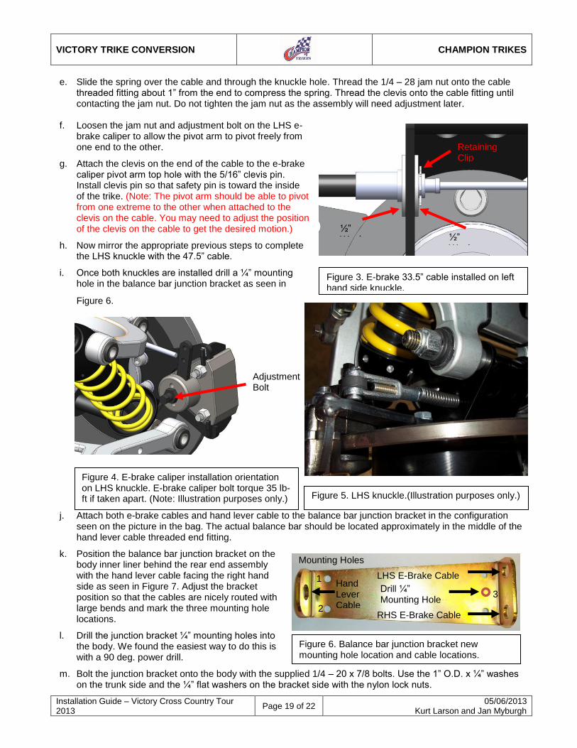
d. Slide one stainless steel ½” USS flat washer over the threaded end fitting onto the conduit end fitting of the 33.5” cable and push through the knuckle mounting hole. Position another ½” washer on the opposite side of the mounting surface as you continue to push the cable through both holes. Push the retaining clip into the conduit end fitting groove to fix the cable housing to the knuckle. See Figure 3.
3-1/4”
VICTORY TRIKE CONVERSION
CHAMPION TRIKES
Installation Guide – Victory Cross Country Tour 2013
Page 19 of 22 05/06/2013
Kurt Larson and Jan Myburgh
½” Washer ½”
Washer
Retaining Clip
Figure 3. E-brake 33.5” cable installed on left hand side knuckle.
Figure 4. E-brake caliper installation orientation on LHS knuckle. E-brake caliper bolt torque 35 lb-ft if taken apart. (Note: Illustration purposes only.)
Adjustment Bolt
Figure 5. LHS knuckle.(Illustration purposes only.)
e. Slide the spring over the cable and through the knuckle hole. Thread the 1/4 – 28 jam nut onto the cable threaded fitting about 1” from the end to compress the spring. Thread the clevis onto the cable fitting until contacting the jam nut. Do not tighten the jam nut as the assembly will need adjustment later.
f. Loosen the jam nut and adjustment bolt on the LHS e-brake caliper to allow the pivot arm to pivot freely from one end to the other.
g. Attach the clevis on the end of the cable to the e-brake caliper pivot arm top hole with the 5/16” clevis pin. Install clevis pin so that safety pin is toward the inside of the trike. (Note: The pivot arm should be able to pivot from one extreme to the other when attached to the clevis on the cable. You may need to adjust the position of the clevis on the cable to get the desired motion.)
h. Now mirror the appropriate previous steps to complete the LHS knuckle with the 47.5” cable.
i. Once both knuckles are installed drill a ¼” mounting hole in the balance bar junction bracket as seen in
Figure 6.
j. Attach both e-brake cables and hand lever cable to the balance bar junction bracket in the configuration seen on the picture in the bag. The actual balance bar should be located approximately in the middle of the hand lever cable threaded end fitting.
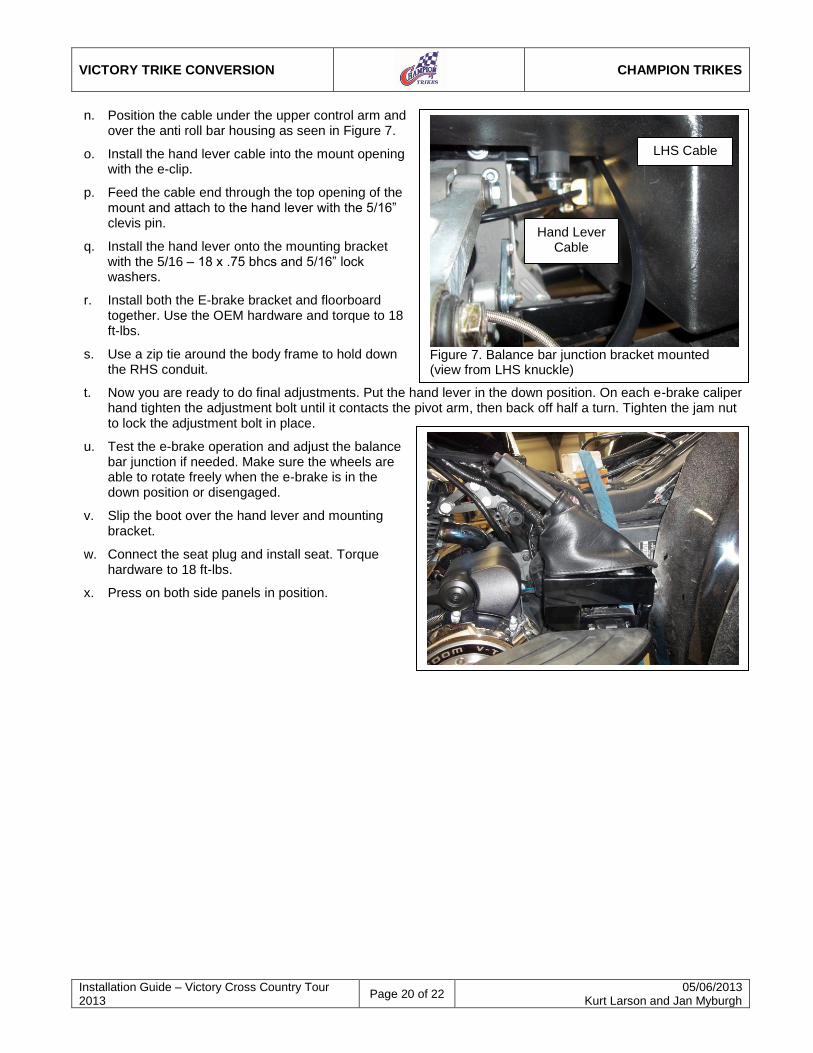
k. Position the balance bar junction bracket on the body inner liner behind the rear end assembly with the hand lever cable facing the right hand side as seen in Figure 7. Adjust the bracket position so that the cables are nicely routed with large bends and mark the three mounting hole locations.
l. Drill the junction bracket ¼” mounting holes into the body. We found the easiest way to do this is with a 90 deg. power drill.
m. Bolt the junction bracket onto the body with the supplied 1/4 – 20 x 7/8 bolts. Use the 1” O.D. x ¼” washes on the trunk side and the ¼” flat washers on the bracket side with the nylon lock nuts.
Figure 6. Balance bar junction bracket new mounting hole location and cable locations.
Mounting Holes
2
1
3 Drill ¼” Mounting Hole
LHS E-Brake Cable Hand Lever Cable
RHS E-Brake Cable
VICTORY TRIKE CONVERSION
CHAMPION TRIKES
Installation Guide – Victory Cross Country Tour 2013
Page 20 of 22 05/06/2013
Kurt Larson and Jan Myburgh
Figure 7. Balance bar junction bracket mounted (view from LHS knuckle)
n. Position the cable under the upper control arm and over the anti roll bar housing as seen in Figure 7.
o. Install the hand lever cable into the mount opening with the e-clip.
p. Feed the cable end through the top opening of the mount and attach to the hand lever with the 5/16” clevis pin.
q. Install the hand lever onto the mounting bracket with the 5/16 – 18 x .75 bhcs and 5/16” lock washers.
r. Install both the E-brake bracket and floorboard together. Use the OEM hardware and torque to 18 ft-lbs.
s. Use a zip tie around the body frame to hold down the RHS conduit.
t. Now you are ready to do final adjustments. Put the hand lever in the down position. On each e-brake caliper hand tighten the adjustment bolt until it contacts the pivot arm, then back off half a turn. Tighten the jam nut to lock the adjustment bolt in place.
u. Test the e-brake operation and adjust the balance bar junction if needed. Make sure the wheels are able to rotate freely when the e-brake is in the down position or disengaged.
v. Slip the boot over the hand lever and mounting bracket.
w. Connect the seat plug and install seat. Torque hardware to 18 ft-lbs.
x. Press on both side panels in position.
Hand Lever Cable
LHS Cable
VICTORY TRIKE CONVERSION
CHAMPION TRIKES
Installation Guide – Victory Cross Country Tour 2013
Page 21 of 22 05/06/2013
Kurt Larson and Jan Myburgh
3.12 Wheel and Tire Installation
a. Install wheels and torque nuts to 75 ft. lbs.
b. Set tire pressure to 22-25 psi.
3.13 Antenna Replacement
Champion recommends using a digital electronic hidden antenna for Vulcan models with a radio and no tour box. For example, a replacement antenna from Dakota Digital model ANT-2000 is available. See www.dakotadigital.com for more details.
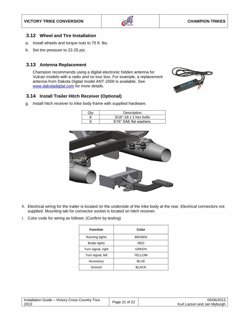
3.14 Install Trailer Hitch Receiver (Optional)
g. Install hitch receiver to trike body frame with supplied hardware.
Qty Description
8 5/16"-18 x 1 hex bolts
8 5/16” SAE flat washers.
h. Electrical wiring for the trailer is located on the underside of the trike body at the rear. Electrical connectors not
supplied. Mounting tab for connector socket is located on hitch receiver.
i. Color code for wiring as follows: (Confirm by testing)
Function Color
Running lights BROWN
Brake lights RED
Turn signal, right GREEN
Turn signal, left YELLOW
Accessory BLUE
Ground BLACK
VICTORY TRIKE CONVERSION
CHAMPION TRIKES
Installation Guide – Victory Cross Country Tour 2013
Page 22 of 22 05/06/2013
Kurt Larson and Jan Myburgh
4 Shock Adjustment
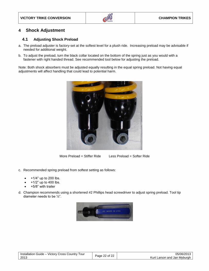
4.1 Adjusting Shock Preload
a. The preload adjuster is factory-set at the softest level for a plush ride. Increasing preload may be advisable if needed for additional weight.
b. To adjust the preload, turn the black collar located on the bottom of the spring just as you would with a fastener with right handed thread. See recommended tool below for adjusting the preload.
Note: Both shock absorbers must be adjusted equally resulting in the equal spring preload. Not having equal adjustments will affect handling that could lead to potential harm.
More Preload = Stiffer Ride Less Preload = Softer Ride
c. Recommended spring preload from softest setting as follows:
+1/4” up to 200 lbs.
+1/2” up to 400 lbs.
+5/8” with trailer
d. Champion recommends using a shortened #2 Phillips head screwdriver to adjust spring preload. Tool tip diameter needs to be ¼”.