TRICOR Coriolis Mass Flow Meters – Manualtricorflow.com/wp-content/uploads/2017/02/TCM_E80... ·...
123
Instruction Manual TCM_E80_M_EN_160520_E010 TRICOR ® Coriolis Mass Flow Meter
Transcript of TRICOR Coriolis Mass Flow Meters – Manualtricorflow.com/wp-content/uploads/2017/02/TCM_E80... ·...
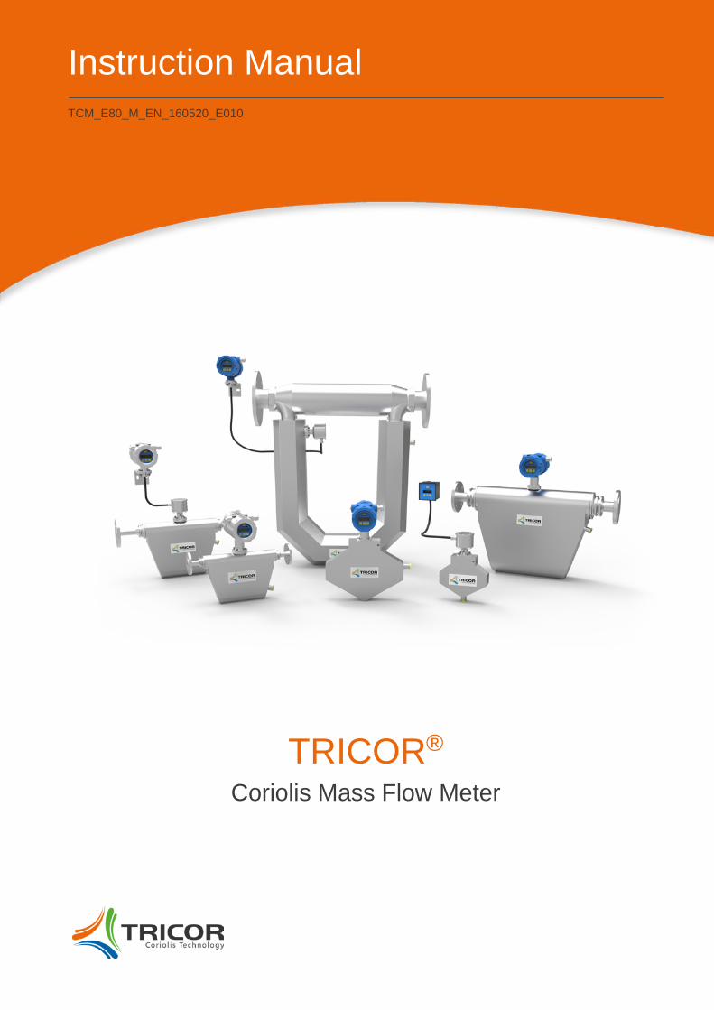
Instruction Manual
TCM_E80_M_EN_160520_E010
TRICOR® Coriolis Mass Flow Meter
2
Version
Version: TCM_E80_M_EN_160520_E010
Manual-Version TCM_E80_M_EN_160520_E010
SW-Version This manual is valid for
Main SW: Mv3.40 and higher
Display SW: Dv3.40 and higher
Version: TCM_E80_M_EN_160520_E010
Index
3
Index 1. GENERAL INFORMATION ........................................................................................................................ 6
1.1. Features ...................................................................................................................................................... 6 1.2. Safety .......................................................................................................................................................... 8 1.2.1. General Safety ............................................................................................................................................ 8 1.2.2. Special Requirements for Ex Installations .................................................................................................. 8 1.2.3. Rupture Disc Handling ................................................................................................................................ 8 1.2.4. Warnings in this Manual.............................................................................................................................. 9 1.3. Ordering Codes and Accessories ............................................................................................................. 10 1.3.1. Ordering Code .......................................................................................................................................... 10 1.3.2. Process Connections ................................................................................................................................ 12 1.3.3. Accessories ............................................................................................................................................... 17 1.4. Measuring Principle TCM ......................................................................................................................... 18
2. GETTING STARTED ................................................................................................................................ 19
2.1. Unpacking ................................................................................................................................................. 19 2.2. Operating Elements .................................................................................................................................. 20 2.2.1. TCE 8***-wall mounted and compact version ........................................................................................... 20 2.2.2. TCE 8***-panel mounted .......................................................................................................................... 21 2.2.3. TCM ****-… (remote version) ................................................................................................................... 22 2.3. Pin Assignments ....................................................................................................................................... 24 2.3.1. TCE 8***-wall mounted and compact version, non-Ex ............................................................................. 24 2.3.2. TCE 8***-wall mounted and compact version, Ex certified ....................................................................... 26 2.3.3. Panel Mount version, non-Ex .................................................................................................................... 28 2.3.4. Panel Mount version TCE 8***-L, Ex certified .......................................................................................... 30 2.4. Quick Start ................................................................................................................................................ 32 2.4.1. First Operation .......................................................................................................................................... 32 2.4.2. CONTROL Menu ...................................................................................................................................... 33 2.4.3. Using the magnet ...................................................................................................................................... 33
3. INSTALLATION ........................................................................................................................................ 34
3.1. Important Installation Guidelines .............................................................................................................. 34 3.1.1. External Vibrations .................................................................................................................................... 34 3.1.2. Inhomogeneous Media ............................................................................................................................. 34 3.1.3. Density CUT OFF for Gas ........................................................................................................................ 35 3.2. Mechanical Installation.............................................................................................................................. 36 3.2.1. Horizontal Installation................................................................................................................................ 36 3.2.2. Vertical Installation .................................................................................................................................... 36 3.2.3. Installation in a Drop line .......................................................................................................................... 37 3.2.4. Critical Installations ................................................................................................................................... 38 3.2.5. Mechanical Installation of the Electronics (remote versions).................................................................... 38 3.3. Electrical Installation ................................................................................................................................. 39 3.3.1. Connecting TCE and TCM ........................................................................................................................ 40 3.3.2. Electrical Installation of the Wall Mount Electronics Version .................................................................... 40 3.3.3. Electrical Installation of the Panel Mount Version .................................................................................... 41 3.3.4. Power Supply and Grounding ................................................................................................................... 42 3.3.5. Connecting the Control Inputs and Outputs.............................................................................................. 44 3.3.6. Connecting the Analog Outputs ................................................................................................................ 45 3.3.7. Connecting the Analog Input .................................................................................................................... 46 3.3.8. Connecting the Relay................................................................................................................................ 46

Index
Version: TCM_E80_M_EN_160520_E010 4
3.4. Ex Installation ............................................................................................................................................ 47
4. MANUAL OPERATION ............................................................................................................................ 48
4.1. Power On Sequence and Principles of Manual Control ........................................................................... 48 4.1.1. Using the Magnet ...................................................................................................................................... 49 4.2. Setup Guidelines ....................................................................................................................................... 50 4.2.1. Meter Mode ............................................................................................................................................... 50 4.2.2. Offset Adjustment ..................................................................................................................................... 50 4.2.3. Flow Filter ................................................................................................................................................. 50 4.2.4. CUT OFF .................................................................................................................................................. 51 4.2.5. STEP RESPONSE .................................................................................................................................... 51 4.2.6. Interaction of the Parameters ................................................................................................................... 51 4.3. Measuring Mode ....................................................................................................................................... 53 4.3.1. Function of the Pushbuttons ..................................................................................................................... 53 4.3.2. Display Selection ...................................................................................................................................... 53 4.3.3. Display Resolution .................................................................................................................................... 53 4.3.4. Resetting the Batch (TOTAL-) Value ........................................................................................................ 53 4.3.5. Event Logging ........................................................................................................................................... 54 4.3.6. Totalizer .................................................................................................................................................... 58 4.4. Offset Adjustment ..................................................................................................................................... 59 4.5. Control Mode ............................................................................................................................................ 60 4.5.1. Function of the Pushbuttons ..................................................................................................................... 60 4.5.2. Submenus in the Main Menu .................................................................................................................... 61 4.5.3. ZERO OFFSET Menu ............................................................................................................................... 62 4.5.4. DISPLAY Menu ......................................................................................................................................... 63 4.5.5. SETUP Menu ............................................................................................................................................ 73 4.5.6. SETUP PARAMETER Menu .................................................................................................................... 74 4.5.7. SETUP FILTER Menu............................................................................................................................... 80 4.5.8. SETUP IN/OUTPUTS Menu ..................................................................................................................... 81 4.5.9. SETUP DATA CONFIGURATION Menu .................................................................................................. 90 4.5.10. SETUP RESET TOTAL Menu .................................................................................................................. 91 4.5.11. SETUP CLEAR LOGS Menu .................................................................................................................... 92 4.5.12. I/O-TEST Menu ......................................................................................................................................... 92 4.5.13. SERVICE Menu ........................................................................................................................................ 94
5. REMOTE OPERATION ............................................................................................................................ 95
5.1. Serial RS485 Interface .............................................................................................................................. 95 5.1.1. Electrical Connection of RS485 Interface ................................................................................................. 95 5.1.2. Usage of the TRICOR Configurator .......................................................................................................... 95 5.1.3. RS485-Interface-Protocol ......................................................................................................................... 95 5.2. HART® ....................................................................................................................................................... 96 5.2.1. Electrical Connection for HART® .............................................................................................................. 96 5.2.2. Device Description File for HART® Interface Protocol .............................................................................. 96 5.3. Foundation Fieldbus® ................................................................................................................................ 96 5.3.1. Electrical Connection for Foundation Fieldbus® ....................................................................................... 96 5.3.2. Device Description File for Foundation Fieldbus® Interface Protocol ....................................................... 96
Version: TCM_E80_M_EN_160520_E010
Index
5
6. SERVICE AND MAINTENANCE .............................................................................................................. 97
6.1. Maintenance ............................................................................................................................................. 97 6.2. Trouble Shooting ....................................................................................................................................... 97 6.3. Changing the Fuses .................................................................................................................................. 98 6.3.1. Changing the fuse with the TCE 8***-wall mounted-**** and compact version ........................................ 98 6.3.2. Changing the fuse with the TCE 8***-S-**** ............................................................................................. 98 6.3.3. Changing the fuses with the Ex versions .................................................................................................. 98 6.4. Calibration ................................................................................................................................................. 99 6.4.1. Temperature Calibration ......................................................................................................................... 100 6.4.2. Air Density Calibration ............................................................................................................................ 100 6.4.3. Water Density Calibration ....................................................................................................................... 101 6.4.4. Flow Calibration ...................................................................................................................................... 103 6.5. Service .................................................................................................................................................... 104 6.6. Global Device Password ......................................................................................................................... 104 6.7. Reloading Factory Settings ..................................................................................................................... 105
7. LISTINGS ............................................................................................................................................... 107
7.1. Warranty ................................................................................................................................................. 107 7.2. Certifications and Compliances .............................................................................................................. 107 7.3. Technical Data ........................................................................................................................................ 109 7.3.1. TCM Transducer - Technical Data for Liquids ........................................................................................ 109 7.3.2. Accuracy for Liquids ................................................................................................................................ 110 7.3.3. TCM Transducer - Technical Data for Gases ......................................................................................... 111 7.3.4. Accuracy for Gases ................................................................................................................................. 112 7.3.5. Technical Data TCE 8000/8100 Transmitter .......................................................................................... 113 7.3.6. Technical Data TCE/TCM Cable ............................................................................................................ 114 7.3.7. Dimensional Drawings ............................................................................................................................ 114 7.4. WEEE and RoHS .................................................................................................................................... 120 7.5. List of Figures ......................................................................................................................................... 121 7.6. List of Tables ........................................................................................................................................... 121
8. CONTACT .............................................................................................................................................. 122

Version: TCM_E80_M_EN_160520_E010
6
General Information
1. General Information
1.1. Features The TRICOR Mass Flow Meter, based on the Coriolis principle, have many advantages compared to other Flow Meter principles.
• No moving parts • High accuracy (0.1%) • Simultaneous measuring of mass flow, density and temperature • Calculation of volume flow as well as mass and volume total • Flushable
The TRICOR Mass Flow Meters are available as compact versions with onsite display and as meter with remote display for wall or panel mount.
All versions are available as standard version as well as Ex certified for hazardous locations (ATEX, IECEx, cCSAus).
The meters provide the following features:
• A graphic display • Menu driven control with soft keys for easy operation (also without manual) • Magnet hall switches for Ex areas • Two freely programmable 4…20 mA outputs • One freely programmable frequency output • One control input and one control output • RS485 interface
Available options are:
• HART® interface • One 4…20 mA input for pressure measurement • Pressure compensation • Foundation Fieldbus® communications
Version: TCM_E80_M_EN_160520_E010
7
General Information
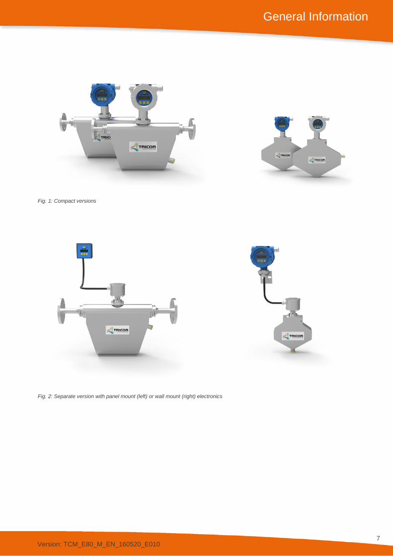
Fig. 1: Compact versions
Fig. 2: Separate version with panel mount (left) or wall mount (right) electronics
Version: TCM_E80_M_EN_160520_E010
8
General Information
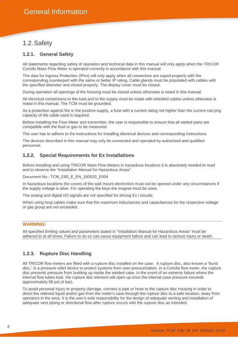
1.2. Safety 1.2.1. General Safety
All statements regarding safety of operation and technical data in this manual will only apply when the TRICOR Coriolis Mass Flow Meter is operated correctly in accordance with this manual.
The data for Ingress Protection (IPnn) will only apply when all connectors are caped properly with the corresponding counterpart with the same or better IP rating. Cable glands must be populated with cables with the specified diameter and closed properly. The display cover must be closed.
During operation all openings of the housing must be closed unless otherwise is noted in this manual.
All electrical connections to the load and to the supply must be made with shielded cables unless otherwise is noted in this manual. The TCM must be grounded.
As a protection against fire in the positive supply, a fuse with a current rating not higher than the current carrying capacity of the cable used is required.
Before installing the Flow Meter and transmitter, the user is responsible to ensure that all wetted parts are compatible with the fluid or gas to be measured.
The user has to adhere to the instructions for installing electrical devices and corresponding instructions.
The devices described in this manual may only be connected and operated by authorized and qualified personnel.
1.2.2. Special Requirements for Ex Installations
Before installing and using TRICOR Mass Flow Meters in hazardous locations it is absolutely needed to read and to observe the “Installation Manual for Hazardous Areas”.
Document No.: TCM_E80_E_EN_160520_E004
In hazardous locations the covers of the wall mount electronics must not be opened under any circumstances if the supply voltage is alive. For operating the keys the magnet must be used.
The analog and digital I/O signals are not specified for driving Ex i circuits.
When using long cables make sure that the maximum inductances and capacitances for the respective voltage or gas group are not exceeded.
WARNING! All specified limiting values and parameters stated in “Installation Manual for Hazardous Areas” must be adhered to at all times. Failure to do so can cause equipment failure and can lead to serious injury or death.
1.2.3. Rupture Disc Handling
All TRICOR flow meters are fitted with a rupture disc installed on the case. A rupture disc, also known a “burst disc,” is a pressure relief device to protect systems from over-pressurization. In a Coriolis flow meter, the rupture disc prevents pressure from building up inside the welded case. In the event of an extreme failure where the internal flow tubes leak, the rupture disc element will open up once the internal case pressure exceeds approximately 58 psi (4 bar).
To avoid personal injury or property damage, connect a pipe or hose to the rupture disc housing in order to direct the relieved liquid and/or gas from the meter’s case through the rupture disc to a safe location, away from operators in the area. It is the user’s sole responsibility for the design of adequate venting and installation of adequate vent piping or directional flow after rupture occurs with the rupture disc as intended.

Version: TCM_E80_M_EN_160520_E010
9
General Information
Particles may discharge when the rupture disc ruptures. These particles may be part of the rupture disc itself, or other environmental matter in the system. It is the user’s sole responsibility to ensure that the particles are directed to a safe location to prevent personal injury or property damage.
WARNING! Take care not to puncture the rupture disc when installing a pipe or fitting to the rupture disc housing, which could cause premature failure of the rupture disc. The flow meter case is filled with a dry inert gas to prevent moisture from building up. Any puncture or other physical damage to the rupture disc would allow moisture into the meter case, compromising the integrity of the meter and potentially resulting in inaccurate measurement results or total meter failure over time.
Fig. 3: Rupture disc locations vary by the meter size and style Fig .4: Warning sticker found near the rupture disc on all meters
1.2.4. Warnings in this Manual
NOTE: Notes provide important information for the correct usage of the equipment. If the notes are not observed, a malfunction of the equipment is possible.
WARNING! Warnings provide very important information for the correct usage of the equipment. Not observing the warnings may lead to danger for the equipment and to danger for health and life of the user

Version: TCM_E80_M_EN_160520_E010
10
General Information
1.3. Ordering Codes and Accessories 1.3.1. Ordering Code
TCE 8 X X X - X - X X X X - X X - X X Housing material: Aluminum 8 0 Housing material: stainless steel (316L) 8 1 Electronics for TCM 0325 to TCM 7900 0 1 Electronics for TCM 028K to TCM 065K 1 1 Electronics for TCM 230K 1 2 Housing Wall mount (housing for ½” NPT cable glands) W Wall mount (housing for M20x1.5 cable glands) I Panel Mount1) S Panel mounted, wide for “Ex”, associated equipment1) L Options Interface2) RS485 (Modbus RTU) S RS485 (Modbus RTU) + HART® A Supply voltage 24 V DC + 90…264 V AC (only housing S+L) B 24 V DC D 90…264 V AC (only housing W, I) M Electronic options Standard S Pressure compensation, 4…20 mA input A Cable length 3 Meters/≈ 10 ft., standard (high temperature) S (H) 6 Meters/≈ 20 ft. (high temperature) B (I) 10 Meters/≈ 33 ft. (high temperature) C (J) 15 Meters/≈ 49 ft. (high temperature) D (O) 20 Meters/≈ 65 ft. (high temperature) E (P) D-SUB Connector, (housing S+L) separate cable required N EX-protection ATEX + IECEx Zone1: Group IIC or IIB, T2…T4 Ex ATEX Zone 2: II3G Ex nA IIC, T2…T4 Gc Exn cCSAus: Class 1, Division 1: Group A, B, C, D or C, D, T2…T43) Ex1 ATEX+IECEx, Zone 1: Group IIC or IIB, T2…T4 and cCSAus: Class 1, Div. 1: Group A, B, C, D or C, D, T2…T43)
Ex3
EAC (TR-CU): Group IIC or IIB, T2 … T43) ExR Customer options (01…99) NOC (Net Oil Computer) 0 1
1) Only for TCE 80XX. 2) Other interfaces on request. 3) For Ex1, Ex3, EAC (TR-CU) the electronic is only available in aluminum housing.

Version: TCM_E80_M_EN_160520_E010
11
General Information
TCM XXXX - X X - X X X X - X X X X - Ex - X X Process connections4) see page 12 ff X X Mechanical options Medium Temperature range: -40 °F…+212 °F (-40 °C…+100 °C) S -40 °F…+302 °F (-40 °C…+150 °C) Exmax: 275 °F (135 °C) H
-40 °F…+158 °F (-40 °C…+70 °C) Ex, compact E -76 °F...+392 °F (-60 °C...+200 °C) T Pressure range With rupture disc max. 4 bar (58 psi) G Mechanical Design Standard S Face to face length Standard (other length on request) S Electronics options Electronics type Junction box Alu (only for replacements) A Z Z S Junction box 1.4404/316L H Z Z S Meter mount, die cast aluminum housing for ½” NPT cable glands5) C Meter mount, die cast aluminum housing for M20x1.5 cable glands5) K Meter mount, stainless steel housing for ½” NPT cable glands5) M Meter mount, stainless steel housing for M20x1.5 cable glands5) O Meter mount electronics TCE 60006) F Interface7) RS485 (Modbus RTU) S RS485 (Modbus RTU) and HART® A RS485 (Modbus RTU) + FF (not with Ex) B FF (Foundation Fieldbus®) D RS485 (Modbus RTU) + USB (only TCE 6000) F Not used Z Supply voltage 24 V DC D 90 … 264 V AC M Not used Z Options Pressure compensation, 4 … 20 mA input A 8 pin I/O connector (TCE 6000 only) B Optical I/O (TCE 6000 only) C No option S EX-protection ATEX + IECEx Zone1: Group IIC or IIB, T2…T4 Ex ATEX Zone 2: II 3G Ex nA IIC, T2…T4 Gc Exn cCSAus: Class 1, Division 1: Group A, B, C, D or C, D, T2…T48) Ex1 ATEX+IECEx: Zone 1: Group IIC or IIB, T2…T4 and cCSAus: Class 1, Division 1: Group A, B, C, D or C, D, T2…T48)9)
Ex3
EAC (TR-CU): Group IIC or IIB, T2 … T48) ExR Special Options NOC (Net Oil Computer) 01
4) For connections not indicated with installation length, please contact manufacturer. 5) For TCM compact version with Ex-protection temperature class T4 only. 6) Ex-protection only available in the option Exn. TCE 6000 electronic is not applicable for TCM 230K. 7) Other interfaces on request. 8) For Ex1, Ex3, EAC (TR-CU) the electronic is only available in aluminum housing. 9) Only with remote electronics.
Version: TCM_E80_M_EN_160520_E010
12
General Information
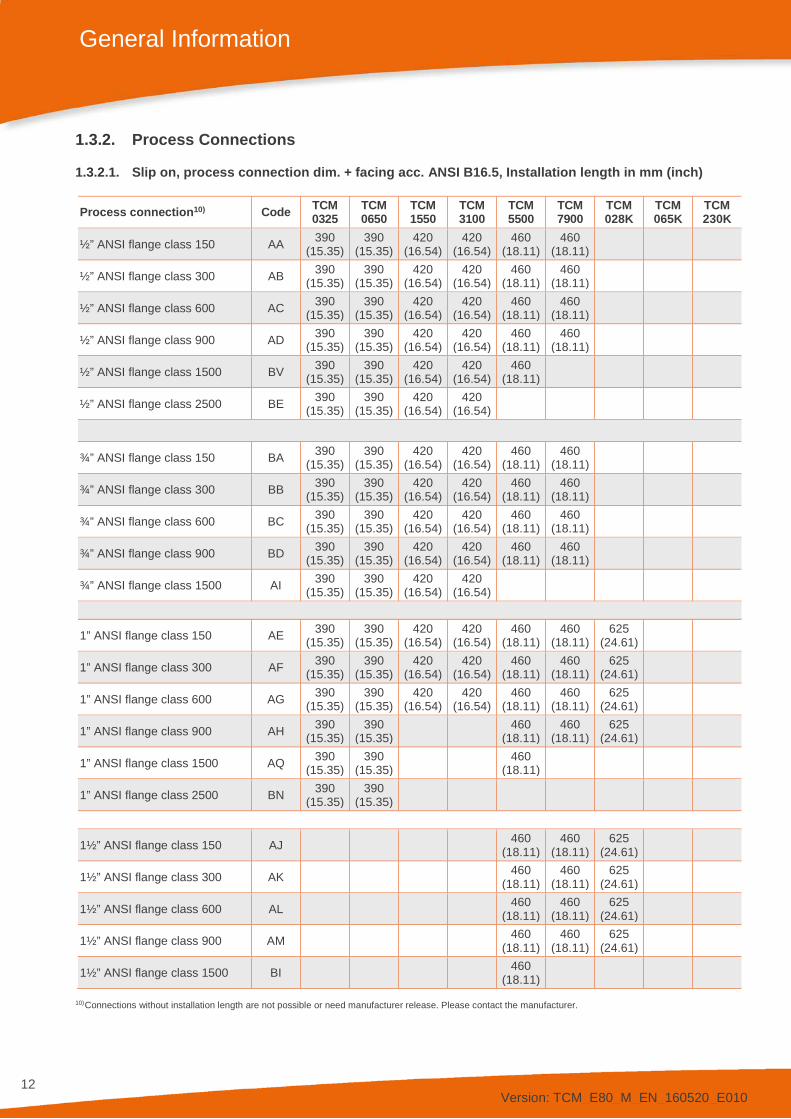
1.3.2. Process Connections
1.3.2.1. Slip on, process connection dim. + facing acc. ANSI B16.5, Installation length in mm (inch)
Process connection10) Code TCM 0325
TCM 0650
TCM 1550
TCM 3100
TCM 5500
TCM 7900
TCM 028K
TCM 065K
TCM 230K
½” ANSI flange class 150 AA 390 (15.35)
390 (15.35)
420 (16.54)
420 (16.54)
460 (18.11)
460 (18.11)
½” ANSI flange class 300 AB 390 (15.35)
390 (15.35)
420 (16.54)
420 (16.54)
460 (18.11)
460 (18.11)
½” ANSI flange class 600 AC 390 (15.35)
390 (15.35)
420 (16.54)
420 (16.54)
460 (18.11)
460 (18.11)
½” ANSI flange class 900 AD 390 (15.35)
390 (15.35)
420 (16.54)
420 (16.54)
460 (18.11)
460 (18.11)
½” ANSI flange class 1500 BV 390 (15.35)
390 (15.35)
420 (16.54)
420 (16.54)
460 (18.11)
½” ANSI flange class 2500 BE 390 (15.35)
390 (15.35)
420 (16.54)
420 (16.54)
¾” ANSI flange class 150 BA 390 (15.35)
390 (15.35)
420 (16.54)
420 (16.54)
460 (18.11)
460 (18.11)
¾” ANSI flange class 300 BB 390 (15.35)
390 (15.35)
420 (16.54)
420 (16.54)
460 (18.11)
460 (18.11)
¾” ANSI flange class 600 BC 390 (15.35)
390 (15.35)
420 (16.54)
420 (16.54)
460 (18.11)
460 (18.11)
¾” ANSI flange class 900 BD 390 (15.35)
390 (15.35)
420 (16.54)
420 (16.54)
460 (18.11)
460 (18.11)
¾” ANSI flange class 1500 AI 390 (15.35)
390 (15.35)
420 (16.54)
420 (16.54)
1” ANSI flange class 150 AE 390 (15.35)
390 (15.35)
420 (16.54)
420 (16.54)
460 (18.11)
460 (18.11)
625 (24.61)
1” ANSI flange class 300 AF 390 (15.35)
390 (15.35)
420 (16.54)
420 (16.54)
460 (18.11)
460 (18.11)
625 (24.61)
1” ANSI flange class 600 AG 390 (15.35)
390 (15.35)
420 (16.54)
420 (16.54)
460 (18.11)
460 (18.11)
625 (24.61)
1” ANSI flange class 900 AH 390 (15.35)
390 (15.35) 460
(18.11) 460
(18.11) 625
(24.61)
1” ANSI flange class 1500 AQ 390 (15.35)
390 (15.35) 460
(18.11)
1” ANSI flange class 2500 BN 390 (15.35)
390 (15.35)
1½” ANSI flange class 150 AJ 460 (18.11)
460 (18.11)
625 (24.61)
1½” ANSI flange class 300 AK 460 (18.11)
460 (18.11)
625 (24.61)
1½” ANSI flange class 600 AL 460 (18.11)
460 (18.11)
625 (24.61)
1½” ANSI flange class 900 AM 460 (18.11)
460 (18.11)
625 (24.61)
1½” ANSI flange class 1500 BI 460 (18.11)
10) Connections without installation length are not possible or need manufacturer release. Please contact the manufacturer.

Version: TCM_E80_M_EN_160520_E010
13
General Information
1.3.2.2. Slip on, process connection dim. + facing acc. ANSI B16.5, Installation length in mm (inch)
Process connection10) Code TCM 0325
TCM 0650
TCM 1550
TCM 3100
TCM 5500
TCM 7900
TCM 028K
TCM 065K
TCM 230K
2” ANSI flange class 150 AN 625 (24.61)
830 (32.68)
2” ANSI flange class 300 AO 625 (24.61)
830 (32.68)
2” ANSI flange class 600 AP 625 (24.61)
830 (32.68)
2” ANSI flange class 900 AR 625 (24.61)
830 (32.68)
2” ANSI flange class 1500 BU 830 (32.68)
2½” ANSI flange class 150 BT 830 (32.68)
2½” ANSI flange class 300 BY 830 (32.68)
2½” ANSI flange class 600 BQ 830 (32.68)
2½” ANSI flange class 900 BW 830 (32.68)
3” ANSI flange class 150 AS 625 (24.61)
830 (32.68)
915 (36.02)
3” ANSI flange class 300 AT 830 (32.68)
915 (36.02)
3” ANSI flange class 600 AU 830 (32.68)
915 (36.02)
3” ANSI flange class 900 AV 830 (32.68)
915 (36.02)
4” ANSI flange class 150 AW 830 (32.68)
915 (36.02)
4” ANSI flange class 300 AX 830 (32.68)
915 (36.02)
4” ANSI flange class 600 AY 830 (32.68)
915 (36.02)
4” ANSI flange class 900 AZ 830 (32.68)
915 (36.02)
5” ANSI flange class 150 BF 915 (36.02)
5” ANSI flange class 300 BG 915 (36.02)
5” ANSI flange class 600 BH 915 (36.02)
5” ANSI flange class 900 BJ 915 (36.02)
6” ANSI flange class 150 BM 915 (36.02)
6” ANSI flange class 600 BX 915 (36.02)
10) Connections without installation length are not possible or need manufacturer release. Please contact the manufacturer.
Version: TCM_E80_M_EN_160520_E010
14
General Information
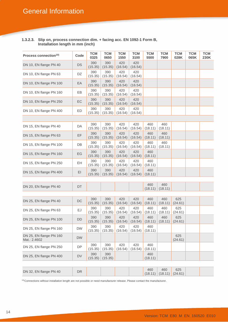
1.3.2.3. Slip on, process connection dim. + facing acc. EN 1092-1 Form B, Installation length in mm (inch)
Process connection10) Code TCM 0325
TCM 0650
TCM 1550
TCM 3100
TCM 5500
TCM 7900
TCM 028K
TCM 065K
TCM 230K
DN 10, EN flange PN 40 DS 390 (15.35)
390 (15.35)
420 (16.54)
420 (16.54)
DN 10, EN flange PN 63 DZ 390 (15.35)
390 (15.35)
420 (16.54)
420 (16.54)
DN 10, EN flange PN 100 EA 390 (15.35)
390 (15.35)
420 (16.54)
420 (16.54)
DN 10, EN flange PN 160 EB 390 (15.35)
390 (15.35)
420 (16.54)
420 (16.54)
DN 10, EN flange PN 250 EC 390 (15.35)
390 (15.35)
420 (16.54)
420 (16.54)
DN 10, EN flange PN 400 ED 390 (15.35)
390 (15.35)
420 (16.54)
420 (16.54)
DN 15, EN flange PN 40 DA 390 (15.35)
390 (15.35)
420 (16.54)
420 (16.54)
460 (18.11)
460 (18.11)
DN 15, EN flange PN 63 EF 390 (15.35)
390 (15.35)
420 (16.54)
420 (16.54)
460 (18.11)
460 (18.11)
DN 15, EN flange PN 100 DB 390 (15.35)
390 (15.35)
420 (16.54)
420 (16.54)
460 (18.11)
460 (18.11)
DN 15, EN flange PN 160 EG 390 (15.35)
390 (15.35)
420 (16.54)
420 (16.54)
460 (18.11)
DN 15, EN flange PN 250 EH 390 (15.35)
390 (15.35)
420 (16.54)
420 (16.54)
460 (18.11)
DN 15, EN flange PN 400 EI 390 (15.35)
390 (15.35)
420 (16.54)
420 (16.54)
460 (18.11)
DN 20, EN flange PN 40 DT 460 (18.11)
460 (18.11)
DN 25, EN flange PN 40 DC 390 (15.35)
390 (15.35)
420 (16.54)
420 (16.54)
460 (18.11)
460 (18.11)
625 (24.61)
DN 25, EN flange PN 63 EJ 390 (15.35)
390 (15.35)
420 (16.54)
420 (16.54)
460 (18.11)
460 (18.11)
625 (24.61)
DN 25, EN flange PN 100 DD 390 (15.35)
390 (15.35)
420 (16.54)
420 (16.54)
460 (18.11)
460 (18.11)
625 (24.61)
DN 25, EN flange PN 160 DW 390 (15.35)
390 (15.35)
420 (16.54)
420 (16.54)
460 (18.11)
DN 25, EN flange PN 160 Mat.: 2.4602 DW 625
(24.61)
DN 25, EN flange PN 250 DP 390 (15.35)
390 (15.35)
420 (16.54)
420 (16.54)
460 (18.11)
DN 25, EN flange PN 400 DV 390 (15.35)
390 (15.35) 460
(18.11)
DN 32, EN flange PN 40 DR 460 (18.11)
460 (18.11)
625 (24.61)
10) Connections without installation length are not possible or need manufacturer release. Please contact the manufacturer.

Version: TCM_E80_M_EN_160520_E010
15
General Information
1.3.2.4. Slip on, process connection dim. + facing acc. EN 1092-1 Form B, Installation length in mm (inch)
Process connection10) Code TCM 0325
TCM 0650
TCM 1550
TCM 3100
TCM 5500
TCM 7900
TCM 028K
TCM 065K
TCM 230K
DN 40, EN flange PN 40 DE 460 (18.11)
460 (18.11)
625 (24.61)
DN 40, EN flange PN 63 EK 460 (18.11)
460 (18.11)
625 (24.61)
DN 40, EN flange PN 100 DF 460 (18.11)
460 (18.11)
625 (24.61)
DN 40, EN flange PN 160 EL 460 (18.11)
DN 40, EN flange PN 250 EM 460 (18.11)
DN 40, EN flange PN 400 EN 460 (18.11)
DN 50, EN flange PN 16 EO 625 (24.61)
830 (32.68)
DN 50, EN flange PN 40 DG 625 (24.61)
830 (32.68)
DN 50, EN flange PN 63 EP 625 (24.61)
830 (32.68)
DN 50, EN flange PN 100 DH 625 (24.61)
830 (32.68)
DN 65, EN flange PN 16 EQ 830 (32.68)
DN 65, EN flange PN 40 DQ 830 (32.68)
DN 65, EN flange PN 63 ER 830 (32.68)
DN 65, EN flange PN 100 ES 830 (32.68)
DN 80, EN flange PN 16 ET 830 (32.68)
915 (36.02)
DN 80, EN flange PN 40 DJ 830 (32.68)
915 (36.02)
DN 80, EN flange PN 63 EU 830 (32.68)
915 (36.02)
DN 80, EN flange PN 100 DK 830 (32.68)
915 (36.02)
10) Connections without installation length are not possible or need manufacturer release. Please contact the manufacturer.
Version: TCM_E80_M_EN_160520_E010
16
General Information
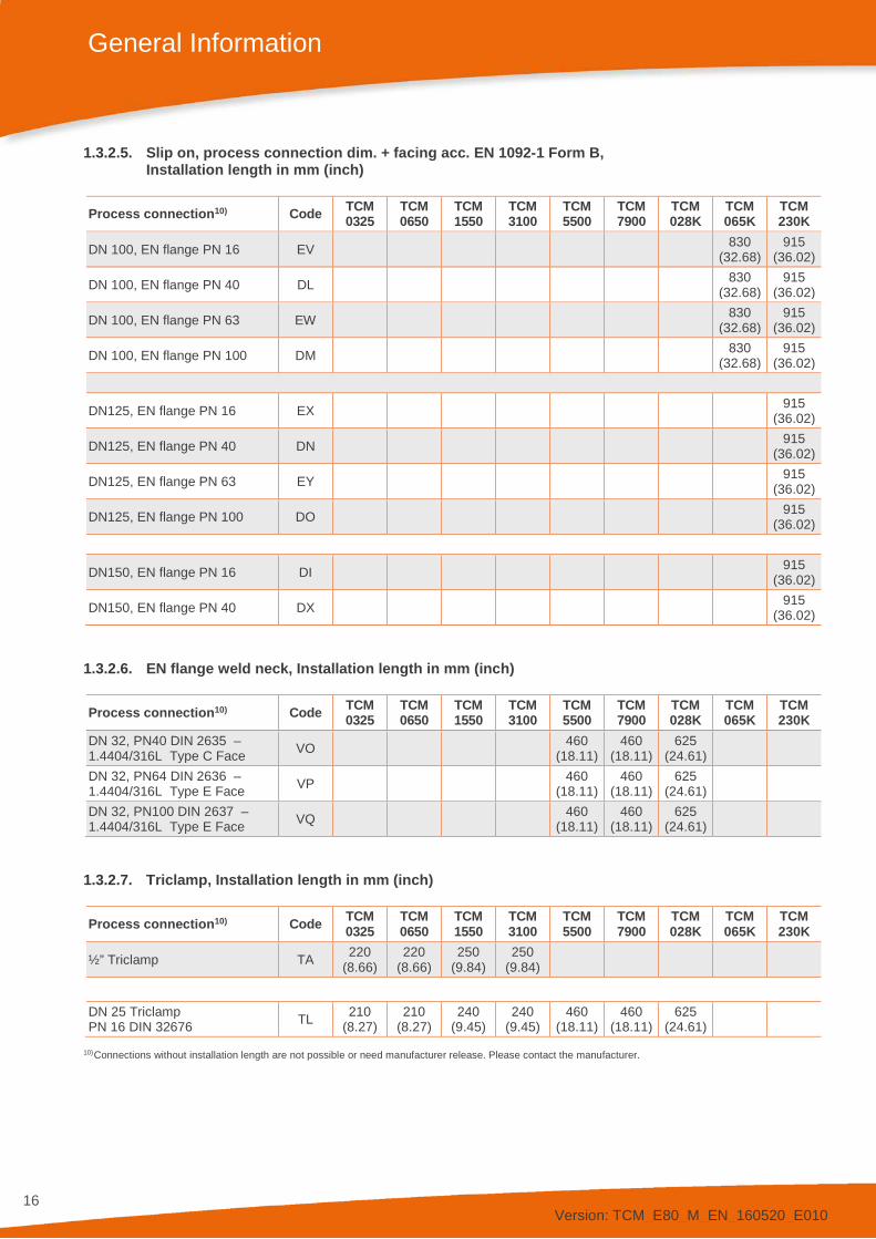
1.3.2.5. Slip on, process connection dim. + facing acc. EN 1092-1 Form B, Installation length in mm (inch)
Process connection10) Code TCM 0325
TCM 0650
TCM 1550
TCM 3100
TCM 5500
TCM 7900
TCM 028K
TCM 065K
TCM 230K
DN 100, EN flange PN 16 EV 830 (32.68)
915 (36.02)
DN 100, EN flange PN 40 DL 830 (32.68)
915 (36.02)
DN 100, EN flange PN 63 EW 830 (32.68)
915 (36.02)
DN 100, EN flange PN 100 DM 830 (32.68)
915 (36.02)
DN125, EN flange PN 16 EX 915 (36.02)
DN125, EN flange PN 40 DN 915 (36.02)
DN125, EN flange PN 63 EY 915 (36.02)
DN125, EN flange PN 100 DO 915 (36.02)
DN150, EN flange PN 16 DI 915 (36.02)
DN150, EN flange PN 40 DX 915 (36.02)
1.3.2.6. EN flange weld neck, Installation length in mm (inch)
Process connection10) Code TCM 0325
TCM 0650
TCM 1550
TCM 3100
TCM 5500
TCM 7900
TCM 028K
TCM 065K
TCM 230K
DN 32, PN40 DIN 2635 – 1.4404/316L Type C Face VO 460
(18.11) 460
(18.11) 625
(24.61)
DN 32, PN64 DIN 2636 – 1.4404/316L Type E Face VP 460
(18.11) 460
(18.11) 625
(24.61)
DN 32, PN100 DIN 2637 – 1.4404/316L Type E Face VQ 460
(18.11) 460
(18.11) 625
(24.61)
1.3.2.7. Triclamp, Installation length in mm (inch)
Process connection10) Code TCM 0325
TCM 0650
TCM 1550
TCM 3100
TCM 5500
TCM 7900
TCM 028K
TCM 065K
TCM 230K
½” Triclamp TA 220 (8.66)
220 (8.66)
250 (9.84)
250 (9.84)
DN 25 Triclamp PN 16 DIN 32676 TL 210
(8.27) 210
(8.27) 240
(9.45) 240
(9.45) 460
(18.11) 460
(18.11) 625
(24.61)
10) Connections without installation length are not possible or need manufacturer release. Please contact the manufacturer.

Version: TCM_E80_M_EN_160520_E010
17
General Information
1.3.3. Accessories
1.3.3.1. TRICOR Connection Cable (TCC) for panel-mounted housing
TCC X X - X X Cable Specifications/Connections
Cable Connector TCE Connector TCM Devices
Standard cable SUB-D, 9pin cable end sleeves (8pol.) TCE 8**1-S- TCE 8**1-L- 0 2
Standard cable SUB-D, 9pin/ Din-Rail mounting cable end sleeves (8pol.) TCE 8**1-S-
TCE 8**1-L- 0 4
High temperature cable SUB-D, 9pin cable end sleeves (8pol.) TCE 8**1-S- TCE 8**1-L- 0 9
High temperature cable SUB-D, 9pin/ Din-Rail mounting cable end sleeves (8pol.) TCE 8**1-S-
TCE 8**1-L- 1 0
Length
3 meter (Standard) (≈ 10 ft.) 0 3
6 meter (≈ 20 ft.) 0 6
10 meter (≈ 33 ft.) 1 0
15 meter (≈ 49 ft.) 1 5
20 meter (≈ 66 ft.) 2 0
1.3.3.2. Additional Accessories
Accessories for TCE 8* electronic Model Code USB interface cable to RS485, 1.8 m (TRICOR configurator) CON.USB.RS-ISO IP65 Protection for TCE-80**-L IPS 9-14 IP65 Protection for TCE-80**-S IPS 9-9 adapter TCE-80**-S and TCE-80**-L for rail mounting HSA 96 Accessories for TCE 6000 electronic Model Code Remote display for TCE 6000 TRD 8001 Connection cable TRD 8001 to TCE 6000, 2 m TRD-TCE-6-2 Connection cable TRD 8001 to TCE 6000, 5 m TRD-TCE-6-5 USB Cable, USB to mini USB M12, 2 m KAB-USB-TCE RS485 to USB connector cable 3 m for TCE 6000; versions FSDS;FFDB, FSDC KAB-RS485-TCE-ISO
Pneumatic Power Gen. Plug M8, 3 pin, 2.5 m cable for TCE 6000 Version FSDC; 7.5 W, 24 V DC TCE 6000-FSDC-SET-PPG
Light pulse emitter and receiver, DIN-rail for TCE 6000 Version FSDC OPTV-02/XO Fiber optic cable for TCE 6000 Version FSDC for FOP 50/60, 10 m (5.5 mm) LW-LA-10 Service and calibration Model Code DAkkS-Calibration (ILAC) according to DIN EN ISO/IEC 17025:2005 DAkkS-Calibration Oxygen cleaning TCM Oxygen cleaning TCM Inspection certificate 3.1 according to DIN 50 049/EN 10204 3.WKZ-0100 TAG Plate (1.4404/316L) TCM-Tag-Plate-1.4404

Version: TCM_E80_M_EN_160520_E010
18
General Information
1.4. Measuring Principle TCM Two parallel flow tubes inside the TCM Flow Meter are vibrating at their natural frequency in opposite direction. Any mass flow passing through the tubes will delay the vibration at the incoming side and accelerate the vibration at the outgoing side. This causes a small time shift between both ends of the tube. This time shift is measured and used to calculate the mass flow through the tubes.
By measuring the natural frequency of the tubes the density of the medium can be calculated.
As both effects are temperature dependent, the temperature is measured by means of an accurate temperature sensor for correcting the temperature effects on flow and density measurement.
As a result a Coriolis Mass Flow Meter measures directly mass flow, density and temperature of the medium. Knowing the mass flow and the density, also the volume flow can be calculated.
Fig. 5: Principle of operation Coriolis Mass Flow Meter

Version: TCM_E80_M_EN_160520_E010
19
Getting Started
2. Getting Started
2.1. Unpacking Verify that you have received the following items:
When you ordered a compact version:
• TCM **** with mounted electronics • Instruction manual
When you ordered a remote version:
• TCM **** with junction box • TCE 8*** • Connecting cable (with TCE 8***-wall mounted and TCE 8***-E just fixed to the TCE,
TCE 8***-panel mounted –L- with separated connection cable) • Instruction manual
Version: TCM_E80_M_EN_160520_E010
20
Getting Started
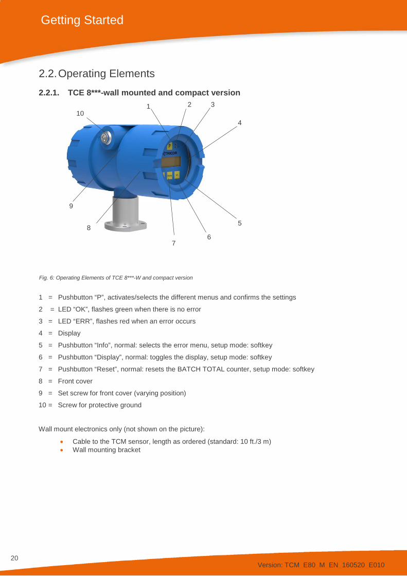
2.2. Operating Elements 2.2.1. TCE 8***-wall mounted and compact version
Fig. 6: Operating Elements of TCE 8***-W and compact version
1 = Pushbutton “P”, activates/selects the different menus and confirms the settings
2 = LED “OK”, flashes green when there is no error
3 = LED “ERR”, flashes red when an error occurs
4 = Display
5 = Pushbutton “Info”, normal: selects the error menu, setup mode: softkey
6 = Pushbutton “Display”, normal: toggles the display, setup mode: softkey
7 = Pushbutton “Reset”, normal: resets the BATCH TOTAL counter, setup mode: softkey
8 = Front cover
9 = Set screw for front cover (varying position)
10 = Screw for protective ground
Wall mount electronics only (not shown on the picture):
• Cable to the TCM sensor, length as ordered (standard: 10 ft./3 m) • Wall mounting bracket
10
1
2
3
4
6 7
5 8
9
Version: TCM_E80_M_EN_160520_E010
21
Getting Started
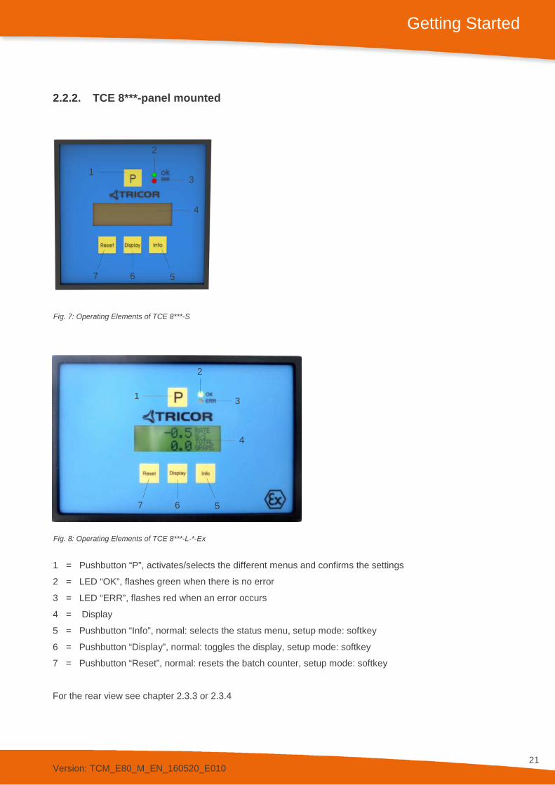
2.2.2. TCE 8***-panel mounted
Fig. 7: Operating Elements of TCE 8***-S
Fig. 8: Operating Elements of TCE 8***-L-*-Ex
1 = Pushbutton “P”, activates/selects the different menus and confirms the settings
2 = LED “OK”, flashes green when there is no error
3 = LED “ERR”, flashes red when an error occurs
4 = Display
5 = Pushbutton “Info”, normal: selects the status menu, setup mode: softkey
6 = Pushbutton “Display”, normal: toggles the display, setup mode: softkey
7 = Pushbutton “Reset”, normal: resets the batch counter, setup mode: softkey
For the rear view see chapter 2.3.3 or 2.3.4
1
2
3
4
5 6 7
1
2
3
4
5 6 7

Version: TCM_E80_M_EN_160520_E010
22
Getting Started
2.2.3. TCM ****-… (remote version)
Fig. 9: Operating Elements TCM
1 = Cable gland for cable to the TCE
2 = Locking screw for screw type terminals
3 = Screw for protective ground (TCM 0325 through 3100 only)
4 = Fluid output, flange/thread as ordered
5 = Fluid input, flange/thread as ordered
6 = M6 mounting threads (back side, option, TCM 0325 through 3100 only)
7 = Rupture Disc (burst pressure: 58 psi/4 bar)
Terminal connection
Terminal Signal Color/Mark Temperature range ≤ 100°C Temperature range >100°C
1 Driver + Gray/1 Gray/1 2 Driver - Pink/2 Gray/2 3 Sensor A + Blue/3 Gray/3 4 Sensor A - Red/4 Gray/4 5 Sensor B + White/5 Gray/5 6 Sensor B - Brown/6 Gray/6 7 PT1000 + Green/7 Gray/7 8 PT1000 - Yellow/8 Gray/8
3
4
1
2
5
6 3
1
2
5
6
4
7 7

Version: TCM_E80_M_EN_160520_E010
23
Getting Started
1 2
3 4
5
6
7
8
1
2
3
4
5
6
7
8
Junction box – Type A (Alu)
Fig. 10: Electrical terminals Junction box – Type A (Alu)
Junction box – Type H (1.4404/316L) Junction box – Type H (1.4404/316L) Medium temperature range ≤ 100°C Medium temperature range >100°C
Fig. 11: Electrical terminals Junction box – Type H (1.4404/316L)

Version: TCM_E80_M_EN_160520_E010
24
Getting Started
2.3. Pin Assignments 2.3.1. TCE 8***-wall mounted and compact version, non-Ex
Fig. 12: Electrical terminals TCE 8***-W and compact version
1 = Terminal screw for protective ground
2 = Switch for terminating resistor for the RS485 interface
3 = Terminal block for interface
4 = Terminal block power supply
5 = Terminal block for I/O signals
6 = Switch for output level (12V/24V) of the frequency and control output
1
4
2
3
5
6

Version: TCM_E80_M_EN_160520_E010
25
Getting Started
TCE Terminal Connections 1 +I1 Current loop 1 positive terminal 2 -I1 Current loop 1 negative terminal 3 +I2 Current loop 2 positive terminal 4 -I2 Current loop 2 negative terminal 5 FOUT Frequency/pulse output 6 CTLOUT Control output 7 CTLIN Control input 8 GND Ground (for pins 5 through 7) 20 COMMON Common (for pins 21 and 22) 21 -RS485 RS485 negative line 22 +RS485 RS485 positive line 30 COMMON Common (for pins 31 and 32) 31 FF- Foundation Fieldbus® negative line 32 FF+ Foundation Fieldbus® positive line 24 V DC Supply 50 +V DC Positive supply voltage (24 V DC) 51 -V DC Supply ground 52 PE Protective Ground 100…240 V AC Supply 90 L Phase (AC voltage) 91 N Neutral 52 PE Protective Ground
NOTE: With option “PRESSURE COMPENSATION“ the current loop 1 (Terminal 1 and 2) is an input.
Version: TCM_E80_M_EN_160520_E010
26
Getting Started
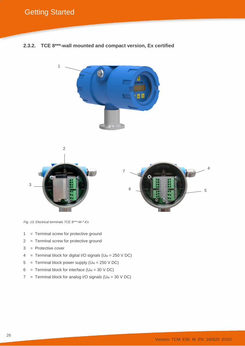
2.3.2. TCE 8***-wall mounted and compact version, Ex certified
Fig. 13: Electrical terminals TCE 8***-W-*-Ex
1 = Terminal screw for protective ground
2 = Terminal screw for protective ground
3 = Protective cover
4 = Terminal block for digital I/O signals (UM = 250 V DC)
5 = Terminal block power supply (UM = 250 V DC)
6 = Terminal block for interface (UM = 30 V DC)
7 = Terminal block for analog I/O signals (UM = 30 V DC)
1
7
6 5
4
3
2

Version: TCM_E80_M_EN_160520_E010
27
Getting Started
TCE Terminal Connections Terminals with UM = 30 V DC 1 +I1 Current loop 1 positive terminal 2 -I1 Current loop 1 negative terminal 3 +I2 Current loop 2 positive terminal 4 -I2 Current loop 2 negative terminal 20 GND Common (for pins 21 and 22) 21 -RS485 RS485 negative line 22 +RS485 RS485 positive line 30 GND Common (for pins 31 and 32) 31 FF- Foundation Fieldbus® negative line 32 FF+ Foundation Fieldbus® positive line
Terminals with UM = 250 V DC 5 FOUT Frequency/pulse output 6 CTLOUT Control output 7 CTLIN Control input 8 GND Ground (for pins 5 through 7) 24 V DC Supply 50 +V DC Positive supply voltage (24 V DC) 51 -V DC Supply ground 52 PE Protective Ground 100…240 V AC Supply 90 L Phase (AC voltage) 91 N Neutral 52 PE Protective Ground
NOTE: With option “PRESSURE COMPENSATION“ the current loop 1 (Terminal 1 and 2) is an input.
Version: TCM_E80_M_EN_160520_E010
28
Getting Started
2.3.3. Panel Mount version, non-Ex
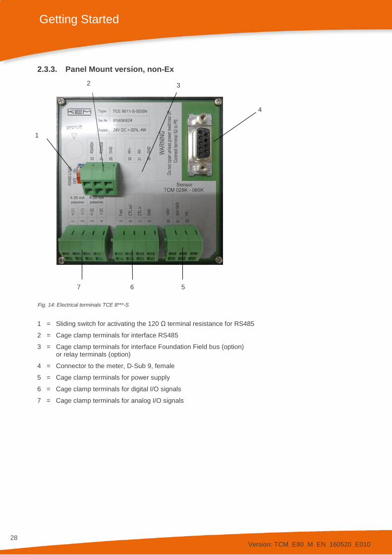
Fig. 14: Electrical terminals TCE 8***-S
1 = Sliding switch for activating the 120 Ω terminal resistance for RS485
2 = Cage clamp terminals for interface RS485
3 = Cage clamp terminals for interface Foundation Field bus (option) or relay terminals (option)
4 = Connector to the meter, D-Sub 9, female
5 = Cage clamp terminals for power supply
6 = Cage clamp terminals for digital I/O signals
7 = Cage clamp terminals for analog I/O signals
7 6 5
4
1
2 3

Version: TCM_E80_M_EN_160520_E010
29
Getting Started
TCE Terminal Connections
1 +I1 Current loop 1 positive terminal 2 -I1 Current loop 1 negative terminal 3 +I2 Current loop 2 positive terminal 4 -I2 Current loop 2 negative terminal 5 FOUT Frequency/pulse output 6 CTLOUT Control output 7 CTLIN Control input 8 GND Ground (for pins 5 through 7) 20 COMMON Common (for pins 21 and 22) 21 -RS485 RS485 negative line 22 +RS485 RS485 positive line 30 COMMON Common (for pins 31 and 32) 31 FF- Foundation Fieldbus® negative line 32 FF+ Foundation Fieldbus® positive line 50 +24 V DC Positive supply voltage (24 V DC) 51 -24 V DC Supply ground 52 PE Protective Ground 90 L Phase (AC voltage) 91 N Neutral 52 PE Protective Ground
Without Foundation Fieldbus® interface there are no terminals 30…32.
With option “Relay Out” there are the relay terminals:
40 REL NO Relay normally open contact 41 REL COM Relay common 42 REL NC Relay normally closed contact
NOTE: With option “PRESSURE COMPENSATION“ the current loop 1 (Terminal 1 and 2) is an input.

Version: TCM_E80_M_EN_160520_E010
30
Getting Started
2.3.4. Panel Mount version TCE 8***-L, Ex certified
Fig. 15: Electrical terminals TCE 8***-L-*-Ex
1 = Sliding switch for activating the 120 Ω terminal resistance for RS485
2 = Terminal blocks for interface (UM = 30 V DC)
3 = Terminal blocks for analog I/O signals (UM = 30 V DC)
4 = Terminal block for power supply (UM = 250 V DC)
5 = Terminal block for digital I/O signals (UM = 250 V DC)
6 = Sliding switch for activating the relay output (option)
7 = Terminal block for relay (UM = 250 V DC)
2 3 1
7 5 4 6

Version: TCM_E80_M_EN_160520_E010
31
Getting Started
TCE Terminal Connections Terminals with UM = 30 V DC 1 +I1 Current loop 1 positive terminal 2 -I1 Current loop 1 negative terminal 3 +I2 Current loop 2 positive terminal 4 -I2 Current loop 2 negative terminal 20 COMMON Common (for pins 21 and 22) 21 -RS485 RS485 negative line 22 +RS485 RS485 positive line 30 COMMON Common (for pins 31 and 32) 31 FF- Foundation Fieldbus® negative line 32 FF+ Foundation Fieldbus® positive line
Terminals with UM = 250 V DC 5 FOUT Frequency/pulse output 6 CTLOUT Control output 7 CTLIN Control input 8 GND Ground (for pins 5 through 7) 40 REL NO Relay normally open contact (option) 41 REL COM Relay common (option) 42 REL NC Relay normally closed contact (option)
50 +24 V DC Positive supply voltage (24 V DC) 51 -24 V DC Supply ground 52 PE Protective Ground 90 L Phase (AC voltage) 91 N Neutral
NOTE: With option “PRESSURE COMPENSATION“ the current loop 1 (Terminal 1 and 2) is an input.
Version: TCM_E80_M_EN_160520_E010
32
Getting Started
2.4. Quick Start WARNING! As for safety and accuracy reasons many precautions must be taken, read chapter 3 carefully before installing the TCM!
In case the TCM has only to be operated without flow for testing or learning purpose, at least the following connections have to be made (see chapter 3.3):
• Connect the TCE to the TCM (only required with the separate version) • Connect the supply voltage • The various inputs and outputs as well as the interface may be connected as well, if those features
are required.
WARNING! If the TRICOR Coriolis Mass Flow Meter is connected to a bigger system, for your personal safety connect the protective ground as well!
WARNING! In hazardous areas it is not allowed to operate the TRICOR Coriolis Mass Flow Meter without proper wiring in accordance with chapter 3.3.6 and with the housing not properly closed!
2.4.1. First Operation
Make sure that all mechanical and electrical connections are made properly.
Switch on the power supply. The LED “OK” will flash green.
After the power up sequence the display shows the preselected values (ex factory: “FLOW” and “BATCH”)
Switch on the flow. The value indicated in the display should be positive.
In case of an error the LED “ERR” will flash red.
As soon as the TCM has reached the operating temperature, make the zero point calibration (see chapter 4.2.2 and 4.5.3 for detailed information):
• Switch off the flow • Wait until the flow through the TCM is zero • Start the zero offset calibration in the “ZERO OFFSET” menu • Wait until the offset procedure is finished • Switch on the flow again
The display can be altered by pressing the pushbutton “Display”.
The internal device status can be viewed by pressing the pushbutton “Info”.
If the function is activated, the BATCH reading can be reset to zero by pressing the pushbutton “Reset”.
To open the control menu press button “P” for three seconds.
Version: TCM_E80_M_EN_160520_E010
33
Getting Started
2.4.2. CONTROL Menu
In the “CONTROL“ menu all configurations can be made. This includes configuration of the analog and digital outputs, customizing the display and other settings.
The menu itself is self-explaining; the function of the softkeys is indicated in the display above the pushbuttons.
To enter the “CONTROL“ menu press the pushbutton “P” for three seconds.
If a global access code is set, the “CONTROL“ menu is completely locked (see chapter 6.6).
With no global access code the submenu “DISPLAY” can be entered without a password as any changes in this submenu will not affect the operation of the TCM.
The submenus “ZERO OFFSET”, “SETUP”, “I/O-TEST” and “SERVICE” are password protected for avoiding unintentional changes of the operating parameters.
For “ZERO OFFSET”, “SETUP” and “I/O-TEST” the password is “2207”, for “SERVICE” refer to chapter 6.
Change the indicated number “2206” with the softkey “UP” to “2207” and confirm with “P”.
Select the desired submenu with the softkeys and confirm with “P”.
Every setting must be confirmed with “P” for storing the setting or with “EXIT” for exiting without storing.
For leaving the “SETUP” menu press “EXIT” until the TCE returns to the main level.
2.4.3. Using the magnet
The explosion-proof variants with the blue Ex d housings provide a magnet to be able to operate the pushbuttons without opening the display cover.
In hazardous, wet and dusty areas the display cover must not be opened to operate the pushbuttons.
Beside every pushbutton there is a hall sensor which can be operated via the magnet attached to the housing.
For operating the pushbuttons hold the magnet to the glass.
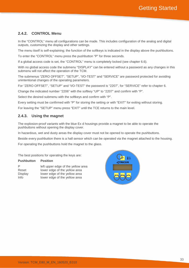
The best positions for operating the keys are:
Pushbutton Position P left upper edge of the yellow area Reset lower edge of the yellow area Display lower edge of the yellow area Info lower edge of the yellow area
Version: TCM_E80_M_EN_160520_E010
34
Installation
3. Installation
3.1. Important Installation Guidelines Coriolis Mass Flow Meters measure the flow of a liquid or gas by vibrating the medium perpendicular to the flow direction and measuring the effect of the inertial force of the medium. Consequently, for best performance the meter must be decoupled from external vibrations and the medium must be homogenous.
It is recommended to install a valve before and after the meter. For the zero calibration both valves should be closed.
3.1.1. External Vibrations
In case of (possible) external vibrations connect the meter mechanically rigidly to a non-vibrating point or – if this is not possible – connect it by means of vibration dampers.
The small meters (TCM 0325 through TCM 3100) can be mounted via optional mounting threads or mounting holes (TCMH 0450) on the back side. All other meters must not be fixed directly, but via holders connected to the external tubing, as close as possible to the flanges of the meter.
In case of vibrating tubes a decoupling via flexible hoses might be recommended.
Piston pumps and other pumps producing a strongly pulsating flow should be decoupled hydraulically via longer pipes, flexible tubes or other measures.
The high pressure changes in short intervals over long time period should be avoided! If it is though an application requirement, please contact our internal sales for technical support!
3.1.2. Inhomogeneous Media
If a liquid might contain gas bubbles or solid particles, care must be taken that the gas bubbles or the solid particles will not remain in the meter.
If a pure liquid or a liquid with possible gas bubbles is to be measured, the meter should be installed horizontally with the meter tubes down. This assures that gas bubbles will not accumulate in the measuring tubes. Meters with U-shaped tubes (TCM 5500 and bigger) can also be mounted vertically.
If a liquid might contain solid particles, the meter should be installed horizontally with the meter tubes up. This assures that the solid particles will not accumulate in the measuring tubes. Meters with U- shaped tubes (TCM 5500 and bigger) can also be mounted vertically.
The TCM 0325 through TCM 3100 and TCMH 0450 must not be mounted vertically, as according to the diamond shaped tube geometry gas bubbles as well as solid particles would accumulate in the meter.
Two phase media with gas bubbles (like foam) or solid particles (like paints or slurry) can be measured without any problems, if the gas bubbles or solid particles are small compared to the tube diameter and evenly distributed. The mounting guidelines, must be observed.
If the amount of gas in the measured fluid or vice versa the amount of fluid in the measured gas goes to high, the flow and density readings get significantly disturbed. The disturbances can be properly detected by means of the measured drive current.
To suppress the faulty measurements, you can define a valid drive current range by specifying drive current thresholds “max drive current” and “min drive current”, as shown in the picture below:

Version: TCM_E80_M_EN_160520_E010
35
Installation
As long as the current drive current stays within the valid range, the flowrate and density will be calculated based on the analog inputs. Otherwise the input signals will be suppressed and the process parameter flow rate and density are set to 0 g/s and 0.001 g/cc.
The drive current thresholds can be specified by means of TRICOR Configurator. The software is license free and can be downloaded from our web site: www.kem-kueppers.com/downloads/software/?lang=en
3.1.3. Density CUT OFF for Gas
If you change from liquid applications to gas applications make sure to change to the DENSITY CUT OFF to 0.0 [units] (see chapter 4.5.6.3).

Version: TCM_E80_M_EN_160520_E010
36
Installation
3.2. Mechanical Installation In accordance with this manual the user should select the installation position which fits the application best. To ensure the highest degree of accuracy and repeatability, care should be taken to affix the TRICOR products in a stable process site and minimize the amount of vibration in the installation environment.
3.2.1. Horizontal Installation
The horizontal installation is the recommended installation.
If the medium might contain solid particles, mount the meter as shown in position “A”, in all other cases as shown in position “B”.
Install the meter to a solid, non-vibrating surface as close to the meter as possible. With the TCM 0325 through TCM 3100 this could be done via the optional mounting threads or with the TCMH 0450 via the mounting holes.
If no non-vibrating surface is available, vibration dampers might be recommended.
Fig. 16: Recommended horizontal Installation
3.2.2. Vertical Installation
TCMH Mass Flow Meters for high pressure applications (>400 bar) should not be mounted in vertical position.
The diamond shaped TCM 0325 through TCM 3100 should not be mounted vertically except you are sure that the medium contains neither gas bubbles nor solid particles.
All other meters can be mounted vertically. This would be the recommended position, if the medium might contain gas bubbles and solid particles.
It is recommended to mount the meter in an upstream position for avoiding that it runs empty during operation.
Fix the meter to a solid, non-vibrating surface as close to the meter as possible.
If no non-vibrating surface is available, vibration dampers might be recommended.

Version: TCM_E80_M_EN_160520_E010
37
Installation
Fig. 17: Vertical Installation
3.2.3. Installation in a Drop line
The diamond shaped TCM 0325 through TCM 3100 should not be mounted vertically except you are sure that the medium contains neither gas bubbles nor solid particles.
TCMH Mass Flow Meters for high pressure applications (>400 bar) should not be mounted in vertical position.
All other meters can be mounted vertically, but flow going down is only allowed as long as there is significant backpressure on the meter to prevent any type of waterfall effect and to assure the meter remains constantly full of the liquid.
Fig. 18: Installation in a Drop Line

Version: TCM_E80_M_EN_160520_E010
38
Installation
3.2.4. Critical Installations
The meters must not be mounted at the highest point of the tubing (A), if gas bubbles are to be expected, or at the lowest point (B), if solid particles are to be expected, as in both cases also the right orientation might not help.
Also the meters must not be mounted in a drop line near the open end (C), as in that case the meter might run empty.
Fig. 19: Critical Installations
3.2.5. Mechanical Installation of the Electronics (remote versions)
TCE 8***-W The wall mount TCE is to be mounted on the wall with 2 screws with 5 mm diameter, about 40 mm apart. For exact dimensions refer to chapter 7.3.7.
TCE 8***-L, TCE 8***-S The housing requires an opening in the panel of 92 mm x 92 mm (TCE 8***-S) or 138 mm x 92 mm (TCE 8***-L) at a maximum panel thickness of 2 mm.
Push the TCE 8*** into the opening. The springs will fix the unit automatically.
For removing the TCE 8*** press the springs towards the housing via a screwdriver.
WARNING! For mounting the TCM in hazardous areas refer to the “Installation Manual for Hazardous Areas”.

Version: TCM_E80_M_EN_160520_E010
39
Installation
3.3. Electrical Installation Make sure that the TCM is properly mounted and the process input and output are connected before making the electrical connections.
The TCM must be grounded.
The TCE requires a regulated DC power supply of 24 V ±20% or a mains voltage of 100 to 240 V AC, depending on the version.
WARNING! Never connect a 24 V only version to the mains supply or vice versa!
The digital inputs and outputs are referred to GND and to the ground potential of the DC supply (= negative pole). The AC supply terminals are electrically isolated from all inputs and outputs.
The ground potential GND is connected to protective ground via a 1 kΩ resistor.The resistor will thermally withstand a potential difference of up to 30 V between PE and GND but for proper operation this difference should be limited to 5 V.
To connect the TCE, shielded cables must be used. The shield should be connected to the case. If the TCM is installed in bigger systems and the shield must not present a DC connection for avoiding high ground loop currents, make the ground connection of the shield via a capacitor of e.g. 100 nF.
WARNING! Improper grounding and shielding may lead to bad EMC behavior or danger to your health!
NOTE: Make sure that all cable and wires are connected and fixed properly before applying power to the TCE.
WARNING! Always switch off the voltage supply before you wire the analog or digital in- and outputs or communication interface. The display module must not be removed if the voltage supply on Coriolis mass meter is on. Otherwise all totals can be reset.

Version: TCM_E80_M_EN_160520_E010
40
Installation
3.3.1. Connecting TCE and TCM
With the remote version the TCE and TCM must be connected before making the other electrical installations. If no TCM is connected to the TCE, the TCE will only show an error message after power on.
For connecting TCE and TCM, only the supplied special cable must be used. For best accuracy the maximum cable length is limited to 20 m.
NOTE: Using different cables or any kind of extension will lead to a degradation of accuracy and stability.
Connecting the cable to the TCM Open the junction box of the TCM.
Feed the cable from the TCE into the cable gland of the TCM and connect the single wires according to Tab. 1. The colors in the table are for the standard cable.
Adjust the position of the cable in the cable glands and close the cable gland.
Terminal Signal Color Wire number
1 Driver + Grey 1 2 Driver - Pink 2 3 Sensor A + Blue 3 4 Sensor A - Red 4 5 Sensor B + White 5 6 Sensor B - Brown 6 7 Pt1000 + Green 7 8 Pt1000 - Yellow 8 PE Protective ground Yellow/green
Tab. 1: Connections TCM ****
Close the top cover of the junction box and fix it with the screw.
Connecting the cable to the TCE 8***-L-* or TCE 8***-S-* Connect the D-Sub connector of the cable to the connector “sensor” on the back side of the housing.
Fasten the fixing screws of the D-SUB connector properly.
3.3.2. Electrical Installation of the Wall Mount Electronics Version
Connect the TCM to the TCE (see chapter 3.3.1, remote version only)
Open the safety screw at the display cover of the TCE with the provided Allen key.
Remove the display cover of the TCE by turning it counter clockwise.
Pull out the display.
Prepare the cable for installation:
• Separate the single wires for about 12 cm (4¾ inches) • Strip the end and cover it with a cable end sleeve • Connect an about 7 cm (2¾ inches) long stranded wire to the shield

Version: TCM_E80_M_EN_160520_E010
41
Installation
Feed the cable through the cable gland.
Connect the shield to the PE screw.
NOTE: In bigger installations a separate PE connection with a high cross section (> 1.5 mm²) is recommended for avoiding high equalizing currents in the shield.
Connect the individual conductors to the cage clamp terminals as required.
Push a small screwdriver into the upper (smaller) opening of the terminal, feed the cable into the bigger opening and pull out the screwdriver.
For the right connections refer to chapter 2.3 and chapter 3.3.4 to 3.3.8.
Adjust the position of the cable in the cable gland in that way that the single conductors remain short but free of tension and fix the cable in the cable gland.
Put in the display again. The display can be positioned in four different orientations, separated by 90°.
Perform – if necessary – a function test and make the necessary settings (see chapter 4.5).
Close the display cover.
Fasten the safety screw if necessary.
3.3.3. Electrical Installation of the Panel Mount Version
Connect the TCM to the TCE (see chapter 3.3.1)
Prepare the cable for installation:
• Separate the single wires as required • Strip the end and cover it with a cable end sleeve • Connect an about 7 cm (2¾ inches) long stranded wire to the shield • Connect the shield to the PE screw.
NOTE: In bigger installations a separate PE connection with a high cross section (> 1.5 mm²) is recommended for avoiding high equalizing currents in the shield.
Connect the individual conductors to the cage clamp terminals as required.
Push a small screwdriver into the upper (smaller) opening of the terminal, feed the cable into the bigger opening and pull out the screwdriver.
For the right connections refer to chapter 2.3 and chapter 3.3.4 to 3.3.8.
Perform – if necessary – a function test and make the necessary settings (see chapter 4.5).

Version: TCM_E80_M_EN_160520_E010
42
Installation
3.3.4. Power Supply and Grounding
3.3.4.1. 24V DC Power Supply
The TCE requires a regulated DC power supply of 24 V ±20%.
The power supply input of the TCE is protected by a fuse. As a protection against fire in case of a short in the supply cable, the output of the power supply must be equipped with a fuse with a rating not higher than the current carrying capacity of the cable used.
For connecting the TCE use shielded cables. If several cables are used, each cable should be shielded properly.
Connect the ground of your power supply to terminal 51 and the 24 V to terminal 50 (see Fig. 20).
Fig. 20: Wiring diagram for power connections, DC operation
Terminal Description 50 Positive supply voltage, 24 V ±20%, referred to pin 51 51 Negative supply voltage 52 Protective ground
The ground terminals 8 and 51 are internally connected together.
Ground and protective ground are internally connected via a 1 kΩ resistor. The resistor will thermally withstand a potential difference of up to 30 V between PE and GND but for proper operation this difference should be limited to 5 V.
3.3.4.2. 100…240V AC Mains Supply
The AC version of the TCE requires a nominal power supply of 100…240 V AC and operates over a range of 90…264 V AC.
The power supply input of the TCE is protected by a 1 A slow blow fuse. As a protection against fire in case of a short in the supply cable, the output of the power supply must be equipped with a fuse with a rating not higher than the current carrying capacity of the cable used.
For the mains powered TCE a good connection of PE is mandatory. The cross section of the PE cable should be at least equivalent to the cross section of the supply cable or to 1 mm², whichever is higher.
Connect the supply to terminal 91 (neutral) and 90 (phase). (see Fig. 21)
TCE 8000

Version: TCM_E80_M_EN_160520_E010
43
Installation
Fig. 21: Wiring diagram for power connections, AC operation
Terminal Description 90 Mains phase, referred to pin 91 91 Mains neutral 52 Protective ground
The ground terminal 8 is not connected to terminal 91.
3.3.4.3. DC and AC supply
The TCE 8***-S-*B** or TCE 8***-L-*B** can be connected to a 24 V DC and a mains supply simultaneously. The unit will operate properly as long as one of the two supplies is present.
TCE 8000
Version: TCM_E80_M_EN_160520_E010
44
Installation
3.3.5. Connecting the Control Inputs and Outputs
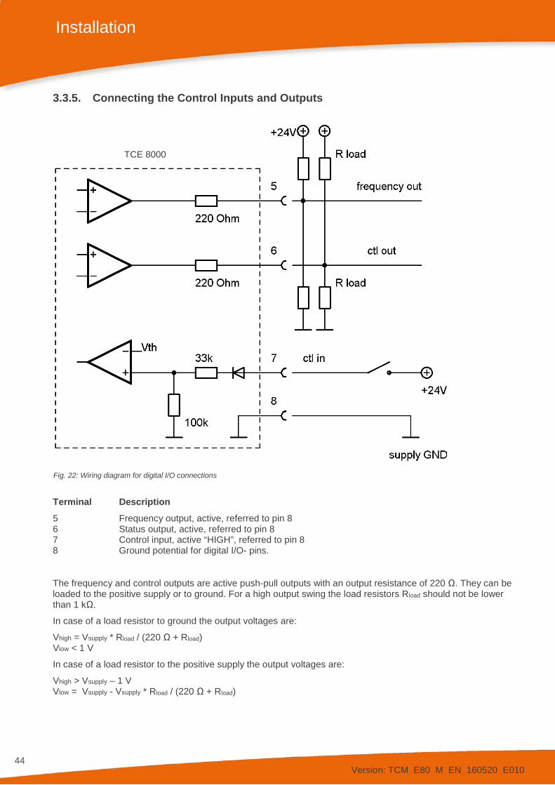
Fig. 22: Wiring diagram for digital I/O connections
Terminal Description 5 Frequency output, active, referred to pin 8 6 Status output, active, referred to pin 8 7 Control input, active “HIGH”, referred to pin 8 8 Ground potential for digital I/O- pins.
The frequency and control outputs are active push-pull outputs with an output resistance of 220 Ω. They can be loaded to the positive supply or to ground. For a high output swing the load resistors Rload should not be lower than 1 kΩ.
In case of a load resistor to ground the output voltages are:
Vhigh = Vsupply * Rload / (220 Ω + Rload) Vlow < 1 V
In case of a load resistor to the positive supply the output voltages are:
Vhigh > Vsupply – 1 V Vlow = Vsupply - Vsupply * Rload / (220 Ω + Rload)
TCE 8000

Version: TCM_E80_M_EN_160520_E010
45
Installation
The control input requires a high voltage of minimum 6.5 V and a minimum input current of 0.1 mA.
The ground terminals 8 and 51 are internally connected together.
Ground and protective ground are internally connected via a 1 kΩ resistor. The resistor will thermally withstand a potential difference of up to 30 V between PE and GND but for proper operation this difference should be limited to 5 V.
3.3.6. Connecting the Analog Outputs
The TCE 8000 provides two independent passive 4…20 mA current loops CURRENT 1 and CURRENT 2.
The current loops are isolated from each other and from the power supply.
For operation an external supply of 8…30 V (nominal 24 V DC) is required.
The minimum voltage between terminal 1 and 2 or 3 and 4 respectively is 8 V.
The minimum load resistance is 0 Ω, the maximum is determined by the supply voltage.
At a given supply voltage the maximum load resistance can be calculated as:
Rload(max) = (Vsupply – 8 V) / 22 mA
For +24 V minus 10% supply this gives a maximum value of 620 Ω.
With a given load resistance, the minimum supply voltage can be calculated as:
Vsupply(min) = 8 V + Rload * 22 mA
Fig. 23: Wiring diagram for 4…20 mA current loop
Terminal Description 1 Positive terminal of the passive 4…20 mA loop 1 2 Negative terminal of the passive 4…20 mA loop 1 3 Positive terminal of the passive 4…20 mA loop 2 4 Negative terminal of the passive 4…20 mA loop 2
As the terminals are floating, the load resistor and the current meter can be placed in the positive or in the negative supply rail.
Connect the shield of the cables to protective ground (terminal 52).
TCE 8000

Version: TCM_E80_M_EN_160520_E010
46
Installation
3.3.7. Connecting the Analog Input
The TCE 8000 with “PRESSURE COMPENSATION“ option provides one passive 4…20 mA output CURRENT 2 and one active 4…20 mA current input CURRENT 1.
The current input is designed to drive a 2-wire passive 4…20 mA pressure sensor. It provides a minimum driving voltage of 16 V.
The negative terminal (2) is internally connected to GND (non Ex version) or to PE (Ex version).
Fig. 24: Wiring diagram for 4…20 mA current input
Terminal Description 1 Positive terminal for a passive 4…20 mA pressure sensor 2 Negative terminal for a passive 4…20 mA pressure sensor
Connect the shield of the cables to protective ground (terminal 52).
WARNING! The analog input is not short-circuit proof. Load currents above 35 mA (permanent load) or above 50 mA (short-time load) can cause damages.
3.3.8. Connecting the Relay
Optionally the panel mount versions of the TCE 8000 series can be equipped with a relay output. The relay is a SPDT type with an nc (normally closed) and an no (normally open) contact.
Terminal Description 40 Relay normally open contact 41 Relay common 42 Relay normally closed contact
The relay is specified for 125 V AC maximum.
TCE 8000

Version: TCM_E80_M_EN_160520_E010
47
Installation
3.4. Ex Installation WARNING! In hazardous locations all installations must only be carried out by qualified personnel!
Switch off all power supplies before installing or uninstalling the TRICOR Coriolis Mass Flow Meter in hazardous locations!
Never connect a TCM to anything other than the specified electronics TCE 8***!
It is extremely important to read and to observe the “Installation Guide for Hazardous Locations”.
Version: TCM_E80_M_EN_160520_E010
48
Manual Operation
4. Manual Operation
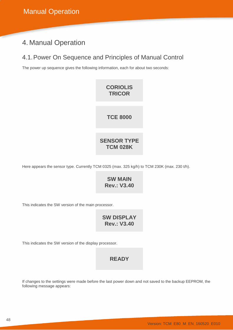
4.1. Power On Sequence and Principles of Manual Control The power up sequence gives the following information, each for about two seconds:
CORIOLIS TRICOR
TCE 8000
SENSOR TYPE
TCM 028K
Here appears the sensor type. Currently TCM 0325 (max. 325 kg/h) to TCM 230K (max. 230 t/h).
SW MAIN
Rev.: V3.40
This indicates the SW version of the main processor.
SW DISPLAY Rev.: V3.40
This indicates the SW version of the display processor.
READY
If changes to the settings were made before the last power down and not saved to the backup EEPROM, the following message appears:

Version: TCM_E80_M_EN_160520_E010
49
Manual Operation
***……. WARNING …….*** NO ACTUAL RAM BACKUP
SEE MANUAL OK
If no pushbutton is pressed the warning will disappear automatically after 10 seconds.
The absence of valid backup data has no influence on the reliability of operation of the meter. The backup is just used to restore the last operation setting in case important parameters of the TCE have misadjusted
For further information refer to chapter 4.5.9.
Now the TCE 8000 switches to the measuring mode, displaying the default screen:
0.000RATE 0.00TOTAL
The green LED “OK” flashes with a one second period. In case of an error the red LED “ERR” flashes.
In manual control the TCE is menu driven and provides two operational modes, the “Measuring Mode” and the “Control Mode”.
In the measuring mode the display shows the preselected measured values and all four pushbuttons have the function printed on them. The switch over between the different display views can be made at any time, by pressing the “Display” button, without influencing neither the measurement nor the digital or analog outputs.
In the control mode the three pushbuttons below the display have varying functions. The actual function is indicated in the display, just above the pushbutton.
In the control menu all necessary settings can be made.
The control menu contains the submenus “ZERO OFFSET”, “DISPLAY”, “SETUP”, “I/O-TEST”, “SERVICE” and “FACTORY”.
For protecting the TRICOR Coriolis Mass Flow Meter against unintentional changes by unauthorized personnel, the menus “ZERO OFFSET”, “SETUP” and “I/O-TEST” are protected by a user password, the menu “SERVICE” by a service password and the menu “FACTORY” by a factory password.
Additionally, a global access code can be set that locks the TRICOR Coriolis Mass Flow Meter completely.
For the description of the control menu see chapter 4.5.
4.1.1. Using the Magnet
The explosion-proof variants with the blue Ex d housings provide a magnet to be able to operate the pushbuttons without opening the display cover.
In hazardous, wet and dusty areas the display cover must not be opened to operate the pushbuttons.
Beside every pushbutton there is a hall sensor which can be operated via the magnet attached to the housing.
For operating the pushbuttons hold the magnet to the glass.
The best positions for operating the keys are:
Pushbutton Position P left upper edge of the yellow area Reset lower edge of the yellow area Display lower edge of the yellow area Info lower edge of the yellow area

Version: TCM_E80_M_EN_160520_E010
50
Manual Operation
4.2. Setup Guidelines Ex factory the TRICOR Mass Flow Meters come with a setup optimized for normal applications. In more than 90% of the applications no further optimization except a zero offset adjustment is required.
The different possibilities for optimizing the settings are described below.
4.2.1. Meter Mode
A Coriolis Mass Flow Meter measures the mass flow and the density and can calculate the volume flow.
For avoiding strange effects with the total values when changing the engineering units, the TCE 8000 can be set up as a Mass Flow Meter, a Volume Flow Meter, a Gas Flow Meter or a Net Oil Computer.
When set up as Mass Flow Meter, only mass flow engineering units can be selected, when set up as Volume Flow Meter or Net Oil Computer, only volume flow engineering units can be selected and when set up as Gas Flow Meter, only standard volume flow engineering units can be selected
For changing the meter mode refer to chapter 4.5.6.1. For the detailed description of the operating modes „REF .VOLUME“ und „NET OIL“ please refer to the Net Oil Computer Addendum, e.g. on the TRICOR website: http://tricorflow.com/support/downloads/
4.2.2. Offset Adjustment
In contrast to a positive displacement meter, a Coriolis Mass Flow Meter does not have a “natural” zero. At no flow the measured time shift is nearly zero, but not exactly. The offset adjustment determines this offset and corrects the measured value correspondingly.
As the offset depends slightly upon the temperature, the density of the medium and the operating pressure, it is strongly recommended to make the offset procedure under working conditions, i.e. with the medium to be measured and at operating pressure and temperature.
To execute an offset adjustment, please refer to chapter 4.3.5 and 4.5.3.
4.2.3. Flow Filter
The raw data of a Mass Flow Meter is relatively noisy. To get a stable reading a filtering of the calculated flow is required.
The filters in the TCE 8000 are set by means of the time constant t. The time constant is the time the output needs, after a jump from a value x to 0, to go to x/e = x/2.72. A higher time constant means more stable reading, but also a slower reaction to changing flows.
A rough relation between the time and the filtered flow value after a jump is:
Elapsed time Remaining Error (% of the step)
1 * t 30 2 * t 10 3 * t 3 4 * t 1
A linear filter as it is realized in the TCE 8000 electronics just delays the flow reading and consequently the “TOTAL” value. Independent of the slope (fast or slow) of the rising and falling flow, the error of the internally calculated TOTAL and at the frequency output are canceled out, if the flow rises from zero (or any other value) and later goes back to the starting value. For getting a correct “TOTAL” via the display or the frequency output, it is just necessary to wait long enough after the flow is switched off.

Version: TCM_E80_M_EN_160520_E010
51
Manual Operation
For best results the TCE 8000 electronics provides two filters.
The “FLOW FILTER” filters the mass flow before calculating the TOTAL or the frequency and current outputs. For normal applications a moderate filtering with t = 1 s is recommended.
The “DISPLAY FILTER” filters the flow display additionally to the “FLOW FILTER”. It does not affect any other parameter or any of the outputs. The default setting is t = 1 s.
If the flow is changing fast or sometimes makes a jump and the outputs have to react as fast as possible, set “FLOW FILTER” to t < 1 s. If nevertheless the flow display has to be stable for better readability, the “DISPLAY FILTER” can be increased.
For setting up the “FLOW FILTER” refer to chapter 4.5.7.1, for the “DISPLAY FILTER” to chapter 4.5.4.2.
4.2.4. CUT OFF
As mentioned above, a Mass Flow Meter has no natural zero and the raw data is noisy. Consequently, with no flow, a meter would indicate and give out continuously a small fluctuating flow.
The parameter “CUT OFF” is used to provide a clear zero. If the calculated and filtered flow is below “CUT OFF”, the meter indicates zero, the “TOTAL” values remain unchanged and the outputs show zero flow as well.
The value for “CUT OFF” must be above the noise floor in the given application and well below the minimum flow to be measured. As a good compromise the default value for “CUT OFF” is 0.5% of the full scale range of the meter.
For setting “CUT OFF” please refer to chapter 4.5.6.3.
4.2.5. STEP RESPONSE
Sometimes it is necessary to react fast to a fast changing flow, but also to have a stable output, if the flow is (mostly) constant. This cannot be achieved by adjusting the flow filter.
The parameter “STEP RESPONSE” provides a fast reaction at fast changing flow, also the filter constant is high.
If the difference between the measured flow and the filtered flow is smaller than the “STEP RESPONSE” value, the flow filter remains active. If the difference is higher than step response, the filter is cleared and filled with the new value.
The recommended value for constant or slowly changing flow is 99% (the default value). If the unit has to react to fast changing flow, the optimum value depends on the individual situation. For ON/OFF operation a value of half the ON flow is recommended.
If “STEP RESPONSE” is set too low, even small changes in flow or even the internal noise will activate the step response function and partially or all the time deactivate the filter, leading to noisy readings and noisy output signals.
For setting “STEP RESPONSE” refer to chapter 4.5.6.4.
4.2.6. Interaction of the Parameters
As each of the three parameters affects the calculation of the flow in a different way, a bad combination of different parameters can lead to systematical errors.
FLOW FILTER and CUT OFF If the filter constant is set to a high value, the calculated flow is delayed compared to the actual flow. In ON-OFF operation this leads to the fact that it takes a long time until the calculated flow settles to the ON or OFF value. The “TOTAL” value remains correct if the TCM measures long enough after the flow got switched off. If “CUT OFF” is set to a high value, the meters stops measuring too early and consequently the calculated “TOTAL” is too low. Also the number of pulses at the frequency output is too low. The error is systematic.

Version: TCM_E80_M_EN_160520_E010
52
Manual Operation
NOTE: In ON-OFF operation high values for the flow filter combined with high values for “CUT OFF” must be avoided! Jumps of the flow not going down to zero are not affected by “CUT OFF”.
FLOW FILTER and STEP RESPONSE A linear filter just delays the flow reading and consequently the total but does not alter the final “TOTAL”.
If the “STEP RESPONSE” is activated, a nonlinear term is added to the filter. The indicated flow will follow more closely the total flow, but the remaining deviation depends on the values for the filter and for “STEP RESPONSE”, but also on the slope of the flow change and on the size of a step.
If the flow changes slowly or a jump is smaller than “STEP RESPONSE”, the function will not be activated and remains linear all the time, producing the normal delay.
If the flow changes fast and the step is higher than “STEP RESPONSE”, the filter will be made faster, the indicated flow follows more closely the actual flow and the delay will be smaller.
In ON-OFF operation with a fast rising and slowly falling flow a systematic positive error is to be expected. If the rising is slow and the falling fast, the error will be negative.
WARNING! If “STEP RESPONSE” is used (e.g. for good reaction to fast changing flow), checking the accuracy for the given application is strongly recommended!
Version: TCM_E80_M_EN_160520_E010
53
Manual Operation
4.3. Measuring Mode 4.3.1. Function of the Pushbuttons
In the measuring mode all pushbuttons have a fixed function:
P Opens the Control Menu if pressed for about three seconds Reset Resets the “BATCH” counter to zero, if the function “KEY RESET” is enabled Display Toggles the display between the preselected settings. Info Opens the info menu
4.3.2. Display Selection
The TCE provides two presettable display views. Ex factory view 1 shows the flow and the “TOTAL” value, view 2 shows density and temperature.
In the “fixed mode” the display view selected by the user remains active until the other view is selected.
For changing from one view to the other just press the pushbutton “Display”.
In the “alternate mode” the TCM toggles between display view 1 and 2 every seven seconds. In this mode the pushbutton “Display” is without function.
For changing the content of the display views, please refer to chapter 4.5.4.
4.3.3. Display Resolution
The measured values can be displayed with 8 digits, including decimal point and sign. The most positive value therefore is “9999999.” (7 digits), the most negative value is “-999999.” (6 digits).
If the decimal point is set in that way that one or more decimal points are displayed and the value to be displayed exceeds the display range, the decimal point will be shifted to the right.
Example: Decimal point setting: x.xxx x.xxx Measured value: 12345.6789 -12345.6789 DP setting changed to: xx.xx xxx.x Displayed value: 12345.67 -12345.6
The new setting for the decimal point will remain, also if the measured value goes down again. It can only be reset to the original settings in the “DISPLAY” menu.
If the decimal point is at the most right position and the measured or calculated value is still too big for being displayed, the display shows “DISPLAY OVERFLOW”. As soon as the measured value returns into the displayable range, the error message disappears and the display shows the value.
If the display shows “DISPLAY OVERFLOW”, change the engineering units. If any “TOTAL” display shows “DISPLAY OVERFLOW”, you can also reset the “TOTAL” values. (see chapter 4.5.10).
4.3.4. Resetting the Batch (TOTAL-) Value
For easy batching in local operation the TCE provides the possibility to reset the Batch value by pressing the pushbutton “Reset”.
For protecting the TRICOR Coriolis Mass Flow Meter against unintentional resetting, this function can be disabled.
Ex works the function is disabled.
For changing the setting, please refer to chapter 4.5.6.5.

Version: TCM_E80_M_EN_160520_E010
54
Manual Operation
4.3.5. Event Logging
Starting with software version Mv3.40 and Dv3.40, all TRICOR Coriolis mass flow meters include event logging that records events occurring at runtime with a timestamp and a unique code. These events can either be shown on the display or read/reset (erased) via Modbus. The use of event logging is explained below using the display as an example. For a description of access via Modbus, see the Modbus manual (document: “Modbus (RTU) Manual”: chapter 3.6).
There are three event classes:
• INFO: Information that a permissible event has occurred (successful initialisation for example). • WARN: Warning that a generally permissible but possibly problematic event has occurred • ERR:ON or ERR:OFF: Indicates that an error state has occurred (ERR:ON) or is no longer active
(ERR:OFF)
4.3.5.1. Event codes
All events codes are listed below and their meanings are explained.
Error (ERR codes)
Event Code Message on display Meaning ERR:
ON ERR:OFF
0 96 INITIALIZATION FAILED Device initialisation could not be completed successfully. 1 97 AMP. SENSOR A The voltage amplitude induced on Sensor A is too high or
too low. 2 98 AMP. SENSOR B The voltage amplitude induced on Sensor B is too high or
too low. 3 99 MEAS. DELAY OVER 250 The measured time delay is above the specified allowable
limit value 5 101 UNST. DRIVER CURRENT Driver current is too unstable 6 102 PT1000 OUT OF RANGE The value of the temperature sensor is too high or too low
(often indicates a line break or short circuit) 7 103 TUBE FREQ. TOO LOW The frequency of the oscillating tube is below the specified
allowable limit value 8 104 TUBE FREQ. TOO HIGH The frequency of the oscillating tube is above the specified
allowable limit value 9 105 DRIVER CURRENT LOW The driver current is below the specified allowable limit
value 10 106 DRIVER CURRENT HIGH The driver current is above the specified allowable limit
value 17 113 MASS FLOW TOO HIGH The mass flow is above the specified allowable limit value 18 114 MASS FLOW TOO LOW The mass flow is below the specified allowable limit value 19 115 TEMPERATURE TOO HIGH The temperature is above the specified allowable limit value 20 116 TEMPERATURE TOO LOW The temperature is below the specified allowable limit value 21 117 DENSITY TOO HIGH The density is above the specified allowable limit value 22 118 DENSITY TOO LOW The density is below the specified allowable limit value 23 119 PRESSURE TOO HIGH The pressure is above the specified allowable limit value 24 120 PRESSURE TOO LOW The pressure is below the specified allowable limit value
Tab. 2: List of errors (ERR Codes)
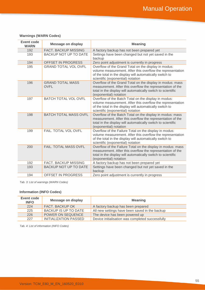
Version: TCM_E80_M_EN_160520_E010
55
Manual Operation
Warnings (WARN Codes)
Event code Message on display Meaning WARN 192 FACT. BACKUP MISSING A factory backup has not been prepared yet 193 BACKUP NOT UP TO DATE Settings have been changed but not yet saved in the
backup 194 OFFSET IN PROGRESS Zero point adjustment is currently in progress 195 GRAND TOTAL VOL OVFL Overflow of the Grand Total on the display in modus:
volume measurement. After this overflow the representation of the total in the display will automatically switch to scientific (exponential) notation
196 GRAND TOTAL MASS OVFL
Overflow of the Grand Total on the display in modus: mass measurement. After this overflow the representation of the total in the display will automatically switch to scientific (exponential) notation
197 BATCH TOTAL VOL OVFL Overflow of the Batch Total on the display in modus: volume measurement. After this overflow the representation of the total in the display will automatically switch to scientific (exponential) notation
198 BATCH TOTAL MASS OVFL Overflow of the Batch Total on the display in modus: mass measurement. After this overflow the representation of the total in the display will automatically switch to scientific (exponential) notation
199 FAIL. TOTAL VOL OVFL Overflow of the Failure Total on the display in modus: volume measurement. After this overflow the representation of the total in the display will automatically switch to scientific (exponential) notation
200 FAIL. TOTAL MASS OVFL Overflow of the Failure Total on the display in modus: mass measurement. After this overflow the representation of the total in the display will automatically switch to scientific (exponential) notation
192 FACT. BACKUP MISSING A factory backup has not been prepared yet 193 BACKUP NOT UP TO DATE Settings have been changed but not yet saved in the
backup 194 OFFSET IN PROGRESS Zero point adjustment is currently in progress
Tab. 3: List of warnings (WARN Codes)
Information (INFO Codes)
Event code Message on display Meaning INFO 224 FACT. BACKUP OK A factory backup has been prepared 225 BACKUP IS UP TO DATE All new settings have been saved in the backup 226 POWER ON SEQUENCE The device has been powered up 227 INITIALIZATION PASSED Device initialisation was completed successfully
Tab. 4: List of information (INFO Codes)
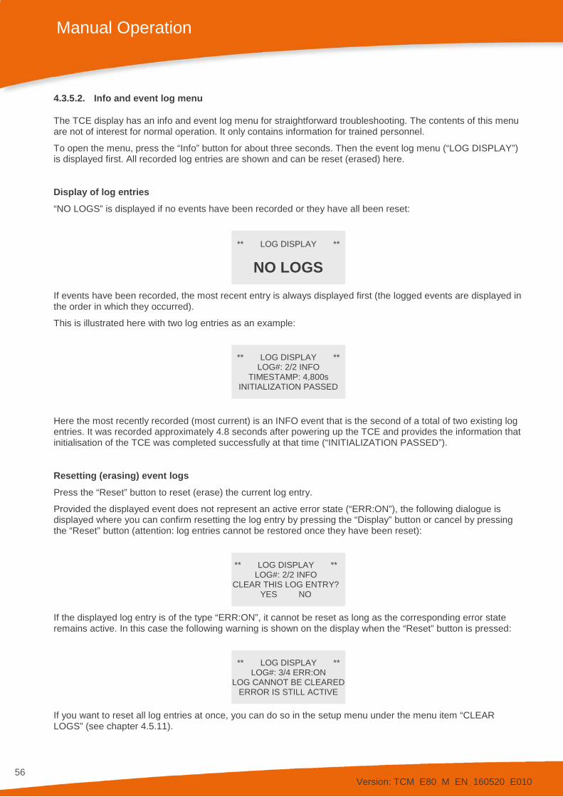
Version: TCM_E80_M_EN_160520_E010
56
Manual Operation
4.3.5.2. Info and event log menu
The TCE display has an info and event log menu for straightforward troubleshooting. The contents of this menu are not of interest for normal operation. It only contains information for trained personnel.
To open the menu, press the “Info” button for about three seconds. Then the event log menu (“LOG DISPLAY”) is displayed first. All recorded log entries are shown and can be reset (erased) here.
Display of log entries “NO LOGS” is displayed if no events have been recorded or they have all been reset:
** LOG DISPLAY **
NO LOGS
If events have been recorded, the most recent entry is always displayed first (the logged events are displayed in the order in which they occurred).
This is illustrated here with two log entries as an example:
** LOG DISPLAY ** LOG#: 2/2 INFO
TIMESTAMP: 4,800s INITIALIZATION PASSED
Here the most recently recorded (most current) is an INFO event that is the second of a total of two existing log entries. It was recorded approximately 4.8 seconds after powering up the TCE and provides the information that initialisation of the TCE was completed successfully at that time (“INITIALIZATION PASSED”).
Resetting (erasing) event logs Press the “Reset” button to reset (erase) the current log entry.
Provided the displayed event does not represent an active error state (“ERR:ON”), the following dialogue is displayed where you can confirm resetting the log entry by pressing the “Display” button or cancel by pressing the “Reset” button (attention: log entries cannot be restored once they have been reset):
** LOG DISPLAY ** LOG#: 2/2 INFO
CLEAR THIS LOG ENTRY? YES NO
If the displayed log entry is of the type “ERR:ON”, it cannot be reset as long as the corresponding error state remains active. In this case the following warning is shown on the display when the “Reset” button is pressed:
** LOG DISPLAY ** LOG#: 3/4 ERR:ON
LOG CANNOT BE CLEARED ERROR IS STILL ACTIVE
If you want to reset all log entries at once, you can do so in the setup menu under the menu item “CLEAR LOGS” (see chapter 4.5.11).
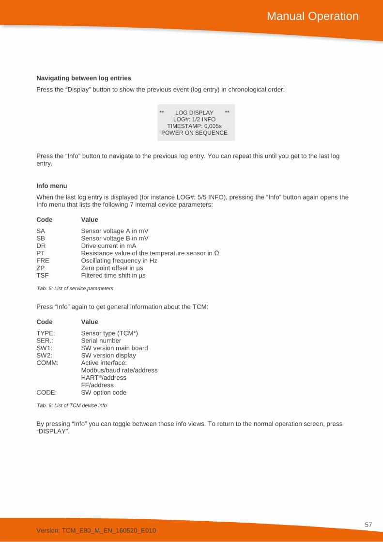
Version: TCM_E80_M_EN_160520_E010
57
Manual Operation
Navigating between log entries Press the “Display” button to show the previous event (log entry) in chronological order:
** LOG DISPLAY ** LOG#: 1/2 INFO
TIMESTAMP: 0,005s POWER ON SEQUENCE
Press the “Info” button to navigate to the previous log entry. You can repeat this until you get to the last log entry.
Info menu When the last log entry is displayed (for instance LOG#: 5/5 INFO), pressing the “Info” button again opens the Info menu that lists the following 7 internal device parameters:
Code Value SA Sensor voltage A in mV SB Sensor voltage B in mV DR Drive current in mA PT Resistance value of the temperature sensor in Ω FRE Oscillating frequency in Hz ZP Zero point offset in µs TSF Filtered time shift in µs
Tab. 5: List of service parameters
Press “Info” again to get general information about the TCM:
Code Value TYPE: Sensor type (TCM*) SER.: Serial number SW1: SW version main board SW2: SW version display COMM: Active interface:
Modbus/baud rate/address HART®/address FF/address
CODE: SW option code
Tab. 6: List of TCM device info
By pressing “Info” you can toggle between those info views. To return to the normal operation screen, press “DISPLAY”.
Version: TCM_E80_M_EN_160520_E010
58
Manual Operation
4.3.6. Totalizer
On the display the following three totalizer can be shown:
• Batch Total • Grand Total • Failure Total
The maximum number of places that can be shown on the display is limited to 7 („1234567“). If a totalizer exceeds this limit, the representation of the total on the display will automatically switch to scientific (exponential) notation. For example, if a totalizer has the value „9999999“ kg and then get incremented by another one kilogram, the totalizer will now display: „1.0000E7“ kg. Thus ensures that no totalizer can be resetted by an overflow in the lifecycle of the device.
Version: TCM_E80_M_EN_160520_E010
59
Manual Operation
4.4. Offset Adjustment For best accuracy the TRICOR Coriolis Mass Flow Meter needs an in situ offset adjustment. This calibration zeroes out the ambient effects and increases the measuring accuracy at low flow.
The offset adjustment must be carried out with the medium to be measured and at a temperature and pressure as close to the normal operation as possible.
Proceed as follows: Operate the TCM for a while under normal operating conditions to make sure that the actual temperature of the TRICOR Coriolis Mass Flow Meter equals the normal operating temperature.
Switch off the flow. For best results use a valve in front and one behind the TCM. If the valves are not close to the TCM and/or only one valve is used, wait long enough to be sure that there is no more flow through the TCM.
NOTE: If there is a residual flow through the TCM or it is exposed to mechanical shocks during the offset adjustment procedure, the resulting value will be wrong.
Start the offset procedure as follows (see also chapter 4.5.3):
• Press “P” for about three seconds • The display shows “ZERO OFFSET” • Press “P” • Change the indicated number with “UP” to “2207“ and confirm with “P” • Press “SLOW” (recommended) or “FAST” • The display shows “MAKE ZERO” for 10 to 30 seconds and counts down to “0” • Confirm with “Info”
Depending on the meter size and the density of the medium, the offset procedure takes about 10 -20 seconds (FAST) or 30…60 seconds (SLOW). During this procedure the red LED will flash.
For an automatic offset adjustment initiated by the central control unit, the control input can be configured as “Initiate offset”. In that case the TCE starts an offset procedure each time a high level is applied to the input.
To configure the input, please refer to chapter 4.5.8.4.

Version: TCM_E80_M_EN_160520_E010
60
Manual Operation
4.5. Control Mode In the control mode the TCE 8000 can be adapted to the individual application. As unintentional changes of the settings might cause problems, some submenus are password protected. Additionally, using the “SERVICE” menu, a global access code can be set that locks the TRICOR Coriolis Mass Flow Meter completely.
To enter the control mode proceed as follows:
Press “P” for about three seconds
If a global access code is set the display shows
ENTER P-ACCESS CODE
0000 LEFT UP EXIT
Change the indicated number with “LEFT” and “UP” to the defined code and confirm with “P”.
If a wrong code is entered, the display shows “ERROR” for about two seconds and then returns to the measurement mode.
When the correct code is entered the display shows
MAIN MENU
ZERO OFFSET UP DOWN EXIT
With the keys “UP” and “DOWN” you can scroll through the main list.
Select the desired submenu and confirm with “P”.
4.5.1. Function of the Pushbuttons
In the setup menu some pushbuttons have changing functions, indicated in the display above the pushbutton:
P Confirms the selection in a list or any kind of inputs
Reset Performs the indicated function
Display Performs the indicated function.
Info (Exit) Performs the indicated function. In most cases exits the current menu point without altering the original value

Version: TCM_E80_M_EN_160520_E010
61
Manual Operation
4.5.2. Submenus in the Main Menu
In the Main Menu the following submenus are addressable:
ZERO OFFSET: Performing the automatic offset adjustment procedure. This submenu is password protected.
DISPLAY: Presetting the display. Changes made in this submenu have no influence on the general function as well on the accuracy of the TCM.
SETUP: Adjusting the TCE 8000 and configuring the inputs and outputs. This submenu is password protected.
I/O-TEST: Setting the outputs to defined values and displaying the actual status of the control inputs for testing the electrical connections. This submenu is password protected.
SERVICE: Calibrating the TCE 8000 with connected TCM. This submenu is password protected.
FACTORY: Service settings for TCE 8000 with connected TCM. This submenu is password protected.

Version: TCM_E80_M_EN_160520_E010
62
Manual Operation
4.5.3. ZERO OFFSET Menu
Select in the main menu
MAIN MENU
ZERO OFFSET UP DOWN EXIT
Press “P”. The display shows
ENTER MENU CODE !
2206 LEFT UP EXIT
Change the indicated number with “LEFT” and “UP” to “2207“ and confirm with “P”.
If a wrong code is entered, the display shows “ERROR” for about two seconds and then asks for a new input.
When the correct code is entered the display shows
START OFFSET PROCEDURE
SLOW FAST EXIT
Press “SLOW” or “FAST” to start the procedure or skip with “EXIT”.
A “SLOW” procedure lasts 30 s to 60 s, a “FAST” procedure 10 s to 20 s.
The display shows
MAKE ZERO (s): 9.5 OLD ZERO: 0.000 µs NEW ZERO: µs
The time counter counts down to zero. The display shows e.g.
MAKE ZERO (s): 0.0 OLD ZERO: 0.000 µs NEW ZERO: 0.123 µs EXIT
Press “EXIT” to return to the measuring mode.

Version: TCM_E80_M_EN_160520_E010
63
Manual Operation
4.5.4. DISPLAY Menu
Select in the main menu
MAIN MENU
DISPLAY UP DOWN EXIT
Press “P”. The display shows
DISPLAY MENU
MASS TOTAL UP DOWN EXIT
The following submenus are available:
MASS TOTAL: Setting the mass TOTAL and Batch units and the mass TOTAL and Batch decimal point.
MASS FLOW: Setting the mass flow units, the mass flow decimal point and a flow filter for the display.
VOL. TOTAL: Setting the volume TOTAL and Batch units and the volume TOTAL and Batch decimal point.
VOL. FLOW: Setting the volume flow units, the volume flow decimal point and a flow filter for the display.
DENSITY: Setting the density units and the density decimal point.
TEMPERATURE: Setting the temperature units and the temperature decimal point.
PRESS DISP: Setting the pressure units (only available with option “PRESSURE COMPENSATION“).
DISP MODE: Setting the content of the two display views and the display mode (static or alternating).
4.5.4.1. MASS TOTAL Menu
In the submenu “MASS TOTAL” the mass “TOTAL” and Batch engineering units and the flow decimal point can be set.
DISPLAY MENU MASS TOTAL UP DOWN EXIT
P MASS TOTAL DISPLAY TOTAL UNITS UP DOWN EXIT
Use the keys “UP” and “DOWN” to select the desired submenu and confirm with “P” or skip with “EXIT”.

Version: TCM_E80_M_EN_160520_E010
64
Manual Operation
The following submenus are available:
TOTAL UNITS: Setting the “TOTAL” units.
TOTAL DP: Setting the “TOTAL” decimal point.
TOTAL UNITS
MASS TOTAL DISPLAY TOTAL UNITS UP DOWN EXIT
P SELECT TOTAL UNITS
KG UP DOWN EXIT
The following units can be selected:
Mass-Unit Description GRAM gram KG kilogram POUNDS pound OUNCES dry ounce TONS metric ton STONES stone MT metric ton
Use the keys “UP” and “DOWN” to select the engineering unit and confirm with “P” or skip with “EXIT”.
TOTAL DP
MASS TOTAL DISPLAY TOTAL DP
UP DOWN EXIT P
SELECT MASS-DP 000.0 KG
LEFT EXIT
Use the key “LEFT” to select the desired decimal point position and confirm with “P” or skip with “EXIT”.
4.5.4.2. MASS FLOW Menu
In the submenu “MASS FLOW” the mass flow engineering unit, the flow decimal point and the flow filter for the display can be set.
DISPLAY MENU MASS FLOW UP DOWN EXIT
P MASS FLOW DISPLAY FLOW UNITS UP DOWN EXIT
Use the keys “UP” and “DOWN” to select the submenu and confirm with “P” or skip with “EXIT”.
The following submenus are available:
FLOW UNITS: Setting the flow units.
FLOW DP: Setting the flow decimal point.
DISP FILTER: Setting the display filter.

Version: TCM_E80_M_EN_160520_E010
65
Manual Operation
FLOW UNITS
MASS FLOW DISPLAY FLOW UNITS UP DOWN EXIT
P SELECT MASS FLOW UNITS
KG/S UP DOWN EXIT
The following units (mass per time) can be selected:
Time-Unit Description S second MIN minute H hour D day
Mass-Unit Description G gram KG kilogram LB pound OZ dry ounce T metric ton ST stone MT metric ton
Use the keys “UP” and “DOWN” to select the engineering unit and confirm with “P” or skip with “EXIT”.
FLOW DP
MASS FLOW DISPLAY FLOW DP
UP DOWN EXIT P
SELECT MASS FLOW DP 000.0 KG/S
LEFT EXIT
Use the key “LEFT” to select the desired decimal point position and confirm with “P” or skip with “EXIT”.
DISP FILTER
MASS FLOW DISPLAY DISP FILTER UP DOWN EXIT
P DISP. FILTER (0-99.9s)
1.00000 s RIGHT UP EXIT
The time constant t is the time the displayed value needs after a jump from a value x to 0 to go to x/e = x/2.72.
NOTE: The display filter only filters the value in the display to provide a more stable reading. It has no influence on the outputs. It is only valid for the mass or volume flow display view! As the display filter is additional to the global filter, the display can never react faster than the outputs.
Use the keys “RIGHT” and “UP” to select the desired time constant and confirm with “P” or skip with “EXIT”.

Version: TCM_E80_M_EN_160520_E010
66
Manual Operation
4.5.4.3. VOL. TOTAL Menu
In the submenu “VOL.TOTAL” the volume “TOTAL” and Batch engineering units and the flow decimal point can be set.
DISPLAY MENU VOL. TOTAL UP DOWN EXIT
P VOLUME TOTAL DISPLAY
TOTAL UNITS UP DOWN EXIT
Use the keys “UP” and “DOWN” to select the desired submenu and confirm with “P” or skip with “EXIT”.
The following submenus are available:
TOTAL UNITS: Setting the “TOTAL” units.
TOTAL DP: Setting the “TOTAL” decimal point.
TOTAL UNITS
VOLUME TOTAL DISPLAY
TOTAL UNITS UP DOWN EXIT
P SELECT TOTAL UNITS
LITER UP DOWN EXIT
The following units can be selected:
Volume-Unit Standard volume Description (if gas measuring mode activated see chapter 4.5.6.1) cm3 Ncm3 (Norm) Cubic Centimeter LITER NL (Norm) Liter GAL SGAL (Standard) US Gallon BBL STB (Standard) US Barrel LOZ SLOZ (Standard) Liquid Ounce IGAL SIGL British (Standard) Gallon IBBL SIBL British (Standard) Barrel m3 Nm3 Cubic Meter kM3 kNm3 (Norm) 1000 Cubic Meter hL hNL (Norm) Hectoliter kL kNL (Norm) Kiloliter ML MNL (Norm) Megaliter CF SCF Cubic Foot MCF MSCF (Standard) 1,000 Cubic Feet MMCF MMSCF 1,000,000 (Standard) Cubic Feet
Use the keys “UP” and “DOWN” to select the engineering unit and confirm with “P” or skip with “EXIT”.
TOTAL DP
VOLUME TOTAL DISPLAY
TOTAL DP UP DOWN EXIT
P SELECT VOLUME-DP
000.0 LITER LEFT EXIT
Use the key “LEFT” to select the desired decimal point position and confirm with “P” or skip with “EXIT”.
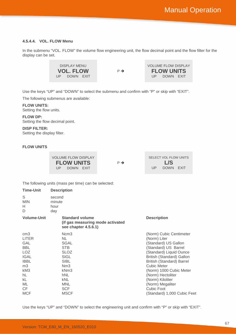
Version: TCM_E80_M_EN_160520_E010
67
Manual Operation
4.5.4.4. VOL. FLOW Menu
In the submenu “VOL. FLOW” the volume flow engineering unit, the flow decimal point and the flow filter for the display can be set.
DISPLAY MENU VOL. FLOW
UP DOWN EXIT P
VOLUME FLOW DISPLAY FLOW UNITS UP DOWN EXIT
Use the keys “UP” and “DOWN” to select the submenu and confirm with “P” or skip with “EXIT”.
The following submenus are available:
FLOW UNITS: Setting the flow units.
FLOW DP: Setting the flow decimal point.
DISP FILTER: Setting the display filter.
FLOW UNITS
VOLUME FLOW DISPLAY FLOW UNITS UP DOWN EXIT
P SELECT VOL FLOW UNITS
L/S UP DOWN EXIT
The following units (mass per time) can be selected:
Time-Unit Description S second MIN minute H hour D day
Volume-Unit Standard volume Description (if gas measuring mode activated see chapter 4.5.6.1) cm3 Ncm3 (Norm) Cubic Centimeter LITER NL (Norm) Liter GAL SGAL (Standard) US Gallon BBL STB (Standard) US Barrel LOZ SLOZ (Standard) Liquid Ounce IGAL SIGL British (Standard) Gallon IBBL SIBL British (Standard) Barrel m3 Nm3 Cubic Meter kM3 kNm3 (Norm) 1000 Cubic Meter hL hNL (Norm) Hectoliter kL kNL (Norm) Kiloliter ML MNL (Norm) Megaliter CF SCF Cubic Foot MCF MSCF (Standard) 1,000 Cubic Feet
Use the keys “UP” and “DOWN” to select the engineering unit and confirm with “P” or skip with “EXIT”.
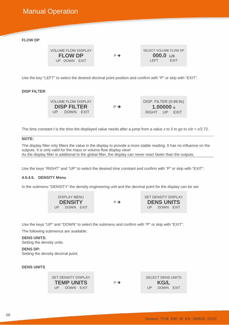
Version: TCM_E80_M_EN_160520_E010
68
Manual Operation
FLOW DP
VOLUME FLOW DISPLAY FLOW DP
UP DOWN EXIT P
SELECT VOLUME FLOW DP
000.0 L/S LEFT EXIT
Use the key “LEFT” to select the desired decimal point position and confirm with “P” or skip with “EXIT”.
DISP FILTER
VOLUME FLOW DISPLAY DISP FILTER
UP DOWN EXIT P
DISP. FILTER (0-99.9s) 1.00000 s
RIGHT UP EXIT
The time constant t is the time the displayed value needs after a jump from a value x to 0 to go to x/e = x/2.72.
NOTE: The display filter only filters the value in the display to provide a more stable reading. It has no influence on the outputs. It is only valid for the mass or volume flow display view! As the display filter is additional to the global filter, the display can never react faster than the outputs.
Use the keys “RIGHT” and “UP” to select the desired time constant and confirm with “P” or skip with “EXIT”.
4.5.4.5. DENSITY Menu
In the submenu “DENSITY” the density engineering unit and the decimal point for the display can be set.
DISPLAY MENU DENSITY
UP DOWN EXIT P
SET DENSITY DISPLAY DENS UNITS UP DOWN EXIT
Use the keys “UP” and “DOWN” to select the submenu and confirm with “P” or skip with “EXIT”.
The following submenus are available:
DENS UNITS: Setting the density units.
DENS DP: Setting the density decimal point.
DENS UNITS
SET DENSITY DISPLAY TEMP UNITS UP DOWN EXIT
P SELECT DENS UNITS
KG/L UP DOWN EXIT

Version: TCM_E80_M_EN_160520_E010
69
Manual Operation
The following engineering units (mass per volume) can be selected:
Unit Description G/cm3 Gram per Cubic Centimeter G/L Gram per Liter KG/m3 Kilogram per Cubic Meter KG/L Kilogram per Liter LB/FT3 Pounds per Cubic Feet LB/GAL Pounds per Gallon BRIX Brix
Use the keys “UP” and “DOWN” to select the engineering unit and confirm with “P” or skip with “EXIT”.
As BRIX specifies the sugar content in water, it is only calculated for densities between 990 and 1130 g/l. If the measured density is outside that range, the display shows “INVALID”.
DENS DP
SET DENSITY DISPLAY DENS DP
UP DOWN EXIT P
SELECT DENSITY DP 000.0 KG/L
LEFT EXIT
Use the key “LEFT” to select the desired decimal point position and confirm with “P” or skip with “EXIT”.
4.5.4.6. TEMPERATURE Menu
In the submenu “TEMPERATURE” the temperature unit and the temperature decimal point for the display can be set.
DISPLAY MENU TEMPERATURE
UP DOWN EXIT P
SET TEMP DISPLAY TEMP UNITS UP DOWN EXIT
Use the keys “UP” and “DOWN” to select the submenu and confirm with “P” or skip with “EXIT”.
The following submenus are available:
TEMP UNITS: Setting the temperature units.
TEMP DP: Setting the temperature decimal point.
TEMP UNITS
SET TEMP DISPLAY TEMP UNITS UP DOWN EXIT
P SELECT TEMP UNITS
°C UP DOWN EXIT
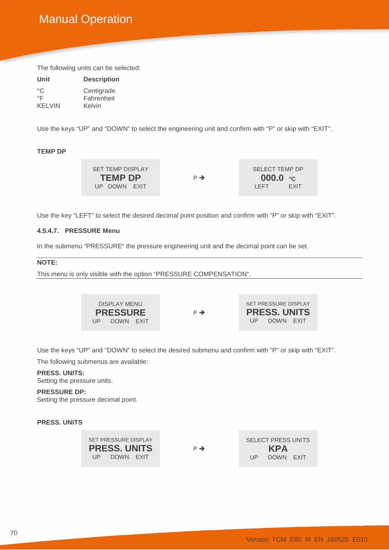
Version: TCM_E80_M_EN_160520_E010
70
Manual Operation
The following units can be selected:
Unit Description °C Centigrade °F Fahrenheit KELVIN Kelvin
Use the keys “UP” and “DOWN” to select the engineering unit and confirm with “P” or skip with “EXIT”.
TEMP DP
SET TEMP DISPLAY TEMP DP
UP DOWN EXIT P
SELECT TEMP DP 000.0 °C
LEFT EXIT
Use the key “LEFT” to select the desired decimal point position and confirm with “P” or skip with “EXIT”.
4.5.4.7. PRESSURE Menu
In the submenu “PRESSURE“ the pressure engineering unit and the decimal point can be set.
NOTE: This menu is only visible with the option “PRESSURE COMPENSATION“.
DISPLAY MENU PRESSURE
UP DOWN EXIT P
SET PRESSURE DISPLAY
PRESS. UNITS UP DOWN EXIT
Use the keys “UP” and “DOWN” to select the desired submenu and confirm with “P” or skip with “EXIT”.
The following submenus are available:
PRESS. UNITS: Setting the pressure units.
PRESSURE DP: Setting the pressure decimal point.
PRESS. UNITS
SET PRESSURE DISPLAY
PRESS. UNITS UP DOWN EXIT
P SELECT PRESS UNITS
KPA UP DOWN EXIT

Version: TCM_E80_M_EN_160520_E010
71
Manual Operation
The following units can be selected:
Unit Description KPA kilopascal MPA megapascal or N/mm² PSI pound per square inch BAR bar
Use the keys “UP” and “DOWN” to select the engineering unit and confirm with “P” or skip with “EXIT”.
PRESS DP
SET PRESSURE DISPLAY
PRESS DP UP DOWN EXIT
P SELECT PRESSURE-DP
00000.0 KPA LEFT EXIT
Use the key “LEFT” to select the desired decimal point position and confirm with “P” or skip with “EXIT”.
4.5.4.8. DISP MODE Menu
In the submenu “DISP MODE” the display mode can be set.
DISPLAY MENU DISP MODE
UP DOWN EXIT P
SET DISPLAY MODE DISPLAY 1
UP DOWN EXIT
Use the keys “UP” and “DOWN” to select the desired submenu and confirm with “P” or skip with “EXIT”.
The following submenus are available:
DISPLAY 1: Setting the content of display view 1.
DISPLAY 2: Setting the content of display view 2.
BACKLIGHT: Switching on and off the backlight.
TIME MODE: Setting fixed or alternating display.
DISPLAY 1
SET DISPLAY MODE DISPLAY 1
UP DOWN EXIT P
SET DISPLAY 1 MODE DUAL LINE
UP DOWN EXIT
Use the keys “UP” and “DOWN” to select dual line or single line and confirm with “P” or skip with “EXIT”.
The display shows:
SELECT LINE1 VALUE
RATE UP DOWN EXIT
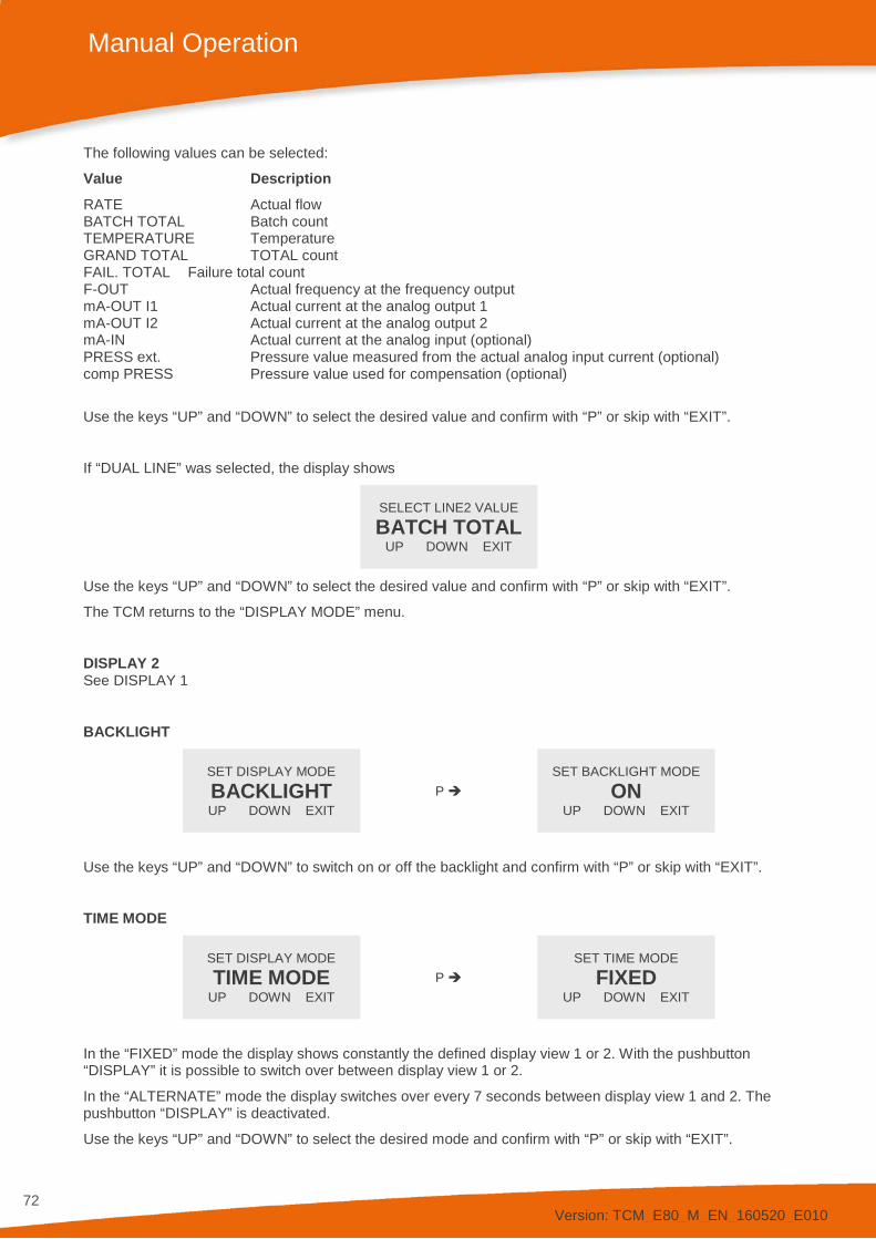
Version: TCM_E80_M_EN_160520_E010
72
Manual Operation
The following values can be selected:
Value Description RATE Actual flow BATCH TOTAL Batch count TEMPERATURE Temperature GRAND TOTAL TOTAL count FAIL. TOTAL Failure total count F-OUT Actual frequency at the frequency output mA-OUT I1 Actual current at the analog output 1 mA-OUT I2 Actual current at the analog output 2 mA-IN Actual current at the analog input (optional) PRESS ext. Pressure value measured from the actual analog input current (optional) comp PRESS Pressure value used for compensation (optional)
Use the keys “UP” and “DOWN” to select the desired value and confirm with “P” or skip with “EXIT”.
If “DUAL LINE” was selected, the display shows
SELECT LINE2 VALUE BATCH TOTAL
UP DOWN EXIT
Use the keys “UP” and “DOWN” to select the desired value and confirm with “P” or skip with “EXIT”.
The TCM returns to the “DISPLAY MODE” menu.
DISPLAY 2 See DISPLAY 1
BACKLIGHT
SET DISPLAY MODE BACKLIGHT UP DOWN EXIT
P SET BACKLIGHT MODE
ON UP DOWN EXIT
Use the keys “UP” and “DOWN” to switch on or off the backlight and confirm with “P” or skip with “EXIT”.
TIME MODE
SET DISPLAY MODE TIME MODE
UP DOWN EXIT P
SET TIME MODE FIXED
UP DOWN EXIT
In the “FIXED” mode the display shows constantly the defined display view 1 or 2. With the pushbutton “DISPLAY” it is possible to switch over between display view 1 or 2.
In the “ALTERNATE” mode the display switches over every 7 seconds between display view 1 and 2. The pushbutton “DISPLAY” is deactivated.
Use the keys “UP” and “DOWN” to select the desired mode and confirm with “P” or skip with “EXIT”.

Version: TCM_E80_M_EN_160520_E010
73
Manual Operation
4.5.5. SETUP Menu
In the “SETUP” menu all settings can be made to adapt the meter to the individual requirements.
Select in the main menu
MAIN MENU SETUP
UP DOWN EXIT
Press “P”. The display shows
ENTER CODE
2206 LEFT UP EXIT
Change the indicated number with “LEFT” and “UP” to “2207“ and confirm with “P”. If a wrong code is entered, the display shows “ERROR” for about two seconds and then asks for a new input.
When the correct code is entered the display shows
SETUP MENU
PARAMETER UP DOWN EXIT
The following submenus are available:
PARAMETER: METER MODE Selection between Mass Flow Meter and Volume Flow Meter CUT OFF Setting the flow CUT OFF value STEP RESP Set Step Response (Option) RESET KEY Enable/disable the key “Reset” FLOW-DIREC Setting up the TCM for reverse flow K-FACTOR Factor for fine scaling the metric variable of the meter FAULT TIME Setting the error response time PRESS. COMP. Enable/disable the “PRESSURE COMPENSATION“ (option) TOTAL COUNT Setting up the mode of operation “TOTAL counter” LANGUAGE Selecting the display language FILTER: FLOW Setting the flow filter time constant DENS Setting the density filter time constant
IN/OUTPUTS: FREQ OUT Configuring the frequency output CTRL OUT Configuring the control output mA OUT Configuring the analog output (4…20 mA) CTRL IN Configuring the control input ANALOG IN Configuring the analog input (option) INTERFACE Configuring the interface
DATA CONFIG: SAVE DATA Saving the actual settings as backup RECALL DATA Recalling the last settings from the backup
RESET TOTAL: RESET TOTAL Resets the TOTAL and the FAIL. TOTAL count to zero.

Version: TCM_E80_M_EN_160520_E010
74
Manual Operation
CLEAR LOGS: CLEAR LOGS Acknowledge (delete) all logged events in the Log memory.
Use the keys “UP” and “DOWN” to select the desired submenu and confirm with “P” or skip with “EXIT”.
4.5.6. SETUP PARAMETER Menu
In the submenu “SETUP/PARAMETER” all user settable internal parameter can be set for adjusting the TCM for a given application.
SETUP MENU PARAMETER UP DOWN EXIT
P PARAMETER MENU
METER MODE UP DOWN EXIT
Use the keys “UP” and “DOWN” to select the desired submenu and confirm with “P” or skip with “EXIT”.
4.5.6.1. METER MODE Menu
In the submenu “METER MODE” the meter mode (“MASS METER” for Mass Flow Meter, “VOLUME METER for Volume Flow Meter, „REF.VOLUME“ for gas measuring mode under reference conditions or „NET OIL“ for Net Oil Computer) can be set.
If “MASS METER” was selected, no volume engineering units can be displayed and vice versa.
PARAMETER MENU METER MODE UP DOWN EXIT
P SELECT METER MODE MASS METER RIGHT UP EXIT
Use the keys “UP” and “DOWN” to select the desired mode and confirm with “P” or skip with “EXIT”.
If the meter mode is changed, the display shows:
WARNING: CHANGING THE METER MODE WILL CAUSE ALL COUNTERS TO RESET PROCEED EXIT
Confirm with “PROCEED” or skip with “EXIT”.
If “PROCEED” is pressed, the display shows:
OPERATION MODE HAS BEEN CHANGED TO
VOLUME METER . OK
If “EXIT” is pressed, the display shows:
THE OPERATION MODE SETTINGS
WERE NOT CHANGED . OK
After “OK” the display returns to the “SETUP PARAMETER” menu.

Version: TCM_E80_M_EN_160520_E010
75
Manual Operation
4.5.6.2. Gas measuring mode (optional)
PARAMETER MENU METER MODE UP DOWN EXIT
P SELECT METER MODE REF. VOLUME
RIGHT UP EXIT
After confirming with “P“, you will be asked to make the settings required for the gas measuring mode. Firstly, you have to enter the reference density to be used in determining the standard volume of gases (𝑉𝑉𝑛𝑛 =𝑚𝑚/𝜌𝜌𝑟𝑟𝑟𝑟𝑟𝑟). Entries are made in the current density unit.
SELECT METER MODE REF. VOLUME UP DOWN EXIT
P REF. FLUID DENSITY
0.050000 g/cm3 RIGHT UP EXIT
The standardized volume flow and the total volume are displayed in standardized volume units. Chapter 4.5.4.5 explains the selection of the unit.
The NetOil-Manual (http://tricorflow.com/support/downloads/ ), page 13 ff., shows additional settings for the gas measuring mode.
4.5.6.3. CUT OFF Menu
In the submenu “CUT OFF” the “CUT OFF” values can be set.
There are 2 different “CUT OFF” values:
FLOW: If the absolute value of the measured and filtered flow is below the “CUT OFF” value, the calculated flow is set to zero and consequently all outputs show zero flow and the “TOTAL” and batch value remain unchanged.
DENSITY: If the current density is below the “CUT OFF” value, the calculated flow is set to zero and consequently all outputs show zero flow and the total and batch value remain unchanged.
The density “CUT OFF” does not influence the density display. Also density below the cut off will be measured and displayed.
PARAMETER MENU CUT OFF
UP DOWN EXIT P
CUT OFF MENU FLOW
UP DOWN EXIT
Use the keys “UP” and “DOWN” to select the desired submenu and confirm with “P” or skip with “EXIT”.

Version: TCM_E80_M_EN_160520_E010
76
Manual Operation
FLOW Typical values for the flow “CUT OFF” are in the range 0.3…1%. With “CUT OFF” values set too low, noise or any external interference might be misinterpreted as real flow. Using too high “CUT OFF” values, low flows might not be correctly registered anymore.
The preset “CUT OFF” should always be significantly smaller than the lowest flow to be measured.
NOTE: Flow “CUT OFF” is defined as mass flow. In volume meter mode recalculate the percentage to mass flow and/or use the density “CUT OFF”.
CUT OFF MENU FLOW
UP DOWN EXIT P
FLOW CUT OFF (%) 0.5
RIGHT UP EXIT
Use the keys “RIGHT” and “UP” to select the desired value and confirm with “P” or skip with “EXIT”.
The display returns to the “CUT OFF” menu.
DENSITY Liquid
CUT OFF MENU DENSITY
UP DOWN EXIT P
LOW DENSITY CUT OFF 0.5 KG/L
RIGHT UP EXIT
Use the keys “RIGHT” and “UP” to select the desired value and confirm with “P” or skip with “EXIT”.
The display returns to the “CUT OFF” menu.
DENSITY Gas
CUT OFF MENU DENSITY
UP DOWN EXIT P
LOW DENSITY CUT OFF 0.0 KG/L
RIGHT UP EXIT
Use the keys “RIGHT” and “UP” to select the desired value and confirm with “P” or skip with “EXIT”.
The display returns to the “CUT OFF” menu.
4.5.6.4. RESP STEP Menu
In the submenu “RESP STEP” the reaction to fast changing flows can be optimized.
NOTE: This submenu is disabled, if the option “FAST RESPONSE” is not implemented.
If the difference between the measured flow and the filtered flow is higher than “STEP RESPONSE”, the filter is cleared and filled with the new value. If it is smaller than the “STEP RESPONSE” value, the flow filter remains active.
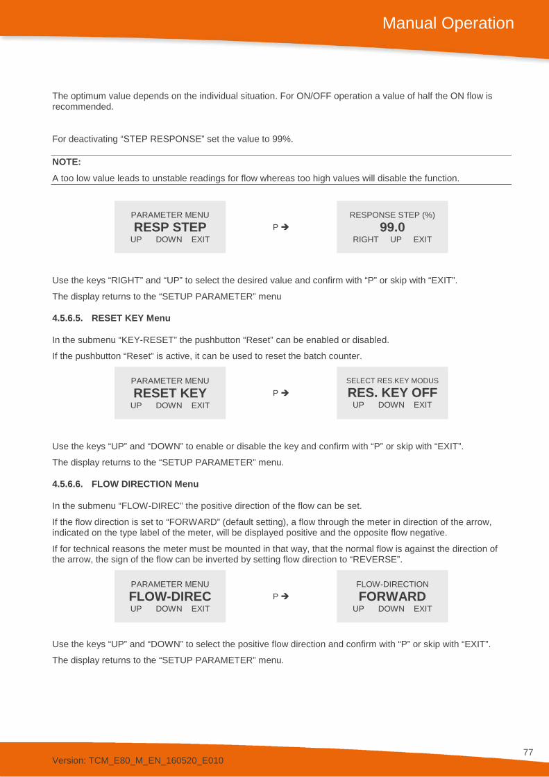
Version: TCM_E80_M_EN_160520_E010
77
Manual Operation
The optimum value depends on the individual situation. For ON/OFF operation a value of half the ON flow is recommended.
For deactivating “STEP RESPONSE” set the value to 99%.
NOTE: A too low value leads to unstable readings for flow whereas too high values will disable the function.
PARAMETER MENU RESP STEP
UP DOWN EXIT P
RESPONSE STEP (%) 99.0
RIGHT UP EXIT
Use the keys “RIGHT” and “UP” to select the desired value and confirm with “P” or skip with “EXIT”.
The display returns to the “SETUP PARAMETER” menu
4.5.6.5. RESET KEY Menu
In the submenu “KEY-RESET” the pushbutton “Reset” can be enabled or disabled.
If the pushbutton “Reset” is active, it can be used to reset the batch counter.
PARAMETER MENU RESET KEY
UP DOWN EXIT P
SELECT RES.KEY MODUS
RES. KEY OFF UP DOWN EXIT
Use the keys “UP” and “DOWN” to enable or disable the key and confirm with “P” or skip with “EXIT”.
The display returns to the “SETUP PARAMETER” menu.
4.5.6.6. FLOW DIRECTION Menu
In the submenu “FLOW-DIREC” the positive direction of the flow can be set.
If the flow direction is set to “FORWARD” (default setting), a flow through the meter in direction of the arrow, indicated on the type label of the meter, will be displayed positive and the opposite flow negative.
If for technical reasons the meter must be mounted in that way, that the normal flow is against the direction of the arrow, the sign of the flow can be inverted by setting flow direction to “REVERSE”.
PARAMETER MENU FLOW-DIREC UP DOWN EXIT
P FLOW-DIRECTION FORWARD
UP DOWN EXIT
Use the keys “UP” and “DOWN” to select the positive flow direction and confirm with “P” or skip with “EXIT”.
The display returns to the “SETUP PARAMETER” menu.

Version: TCM_E80_M_EN_160520_E010
78
Manual Operation
4.5.6.7. K-FACTOR Menu
In the submenu “K-FACTOR” the k- factor for the fine tuning of the flow calculation can be set.
Ex works the TRICOR Coriolis Mass Flow Meter is calibrated with a k-factor k = 1.0000. If for any reasons the flow measured by the Mass Flow Meter differs slightly from a flow measured with other means, the value calculated by the TCM can be adjusted by changing the k- factor without the need to perform a new flow calibration.
PARAMETER MENU K-FACTOR
UP DOWN EXIT P
K-FACTOR 1.00000
RIGHT UP EXIT
Use the keys “RIGHT” and “UP” to select the desired value and confirm with “P” or skip with “EXIT”.
The display returns to the “SETUP PARAMETER” menu.
4.5.6.8. FAULT TIME Menu
In the submenu “FAULT TIME” the reaction time of the TCE 8000 in case of an error can be defined.
The “FAULT ON DELAY TIME” is the time an error must be present, before the red LED lights up and the error output signal is activated.
The “FAULT OFF DELAY TIME” is the time an error signal persists on the red LED and on the control output, after the error disappeared.
PARAMETER MENU FAULT TIME UP DOWN EXIT
P
FAULT ON DELAY TIME 2.7000
SECONDS RIGHT UP EXIT
Use the keys “RIGHT” and “UP” to select the desired value and confirm with “P” or skip with “EXIT”.
The display shows
FAULT OFF DELAY TIME 2.7000 SECONDS RIGHT UP EXIT
Use the keys “RIGHT” and “UP” to select the desired value and confirm with “P” or skip with “EXIT”.
The display returns to the “SETUP PARAMETER” menu.
4.5.6.9. PRESS COMP Menu
In the submenu “PRESS. COMP” the operational mode of the “PRESSURE COMPENSATION” (option) can be set.
NOTE: This menu is only visible with the option “PRESSURE COMPENSATION“.

Version: TCM_E80_M_EN_160520_E010
79
Manual Operation
The following modes are possible:
OFF: No pressure compensation.
mA-IN I1: The pressure measured via the analog 4…20 mA input is used for the compensation.
MANUAL: The pressure set manually or via the interface is used for the compensation.
PARAMETER MENU PRESS. COMP.
UP DOWN EXIT P
SELECT P COMP MODUS OFF
UP DOWN EXIT
Use the keys “UP” and “DOWN” to select the desired mode and confirm with “P” or skip with “EXIT”.
Is “mA-IN I1” selected but the status of the analog input is “OFF”, the display shows
CHANGE mA-IN I2 TO PRESSURE TO PROCEED
. OK
Confirm with “OK“. Configure the analog input correspondingly (see chapter 4.5.8.5) and repeat the setting.
If “MANUAL” is selected, the display shows
MANUAL PRESSURE RATE
0. 000 BAR RIGHT UP EXIT
Use the keys “RIGHT” and “UP” to select the desired value and confirm with “P” or skip with “EXIT”.
The display returns to the “PRESS. COMP”. menu.
4.5.6.10. TOTAL COUNT Menu
In the submenu “TOTAL COUNT” the “TOTAL” counter can be configured.
The following operating modes are available:
DEFAULT: The “TOTAL” count includes flow in positive as well as in negative direction. With positive flow the TOTAL value increases, with negative flow it decreases.
FORWARD: The “TOTAL” count includes only flow in positive direction. With negative flow the TOTAL value does not change.
BACKWARD: The “TOTAL” count includes only flow in negative direction. With positive flow the TOTAL value does not change.

Version: TCM_E80_M_EN_160520_E010
80
Manual Operation
PARAMETER MENU TOTAL COUNT
UP DOWN EXIT P
SELECT TOTALIZER MODE
DEFAULT UP DOWN EXIT
Use the keys “UP” and “DOWN” to select the mode and confirm with “P” or skip with “EXIT”.
The display returns to the “SETUP PARAMETER” menu.
4.5.6.11. LANGUAGE Menu
In the submenu “LANGUAGE” the language used in the display can be selected.
For the time being, English and Russian can be selected.
PARAMETER MENU LANGUAGE
UP DOWN EXIT P
SELECT LANGUAGE ENGLISH
UP DOWN EXIT
Use the keys “UP” and “DOWN” to select the language and confirm with “P” or skip with “EXIT”.
The display returns to the “SETUP PARAMETER” menu.
4.5.7. SETUP FILTER Menu
In the submenu “SETUP FILTER” the filters of TCE can be configured.
SETUP MENU FILTER
UP DOWN EXIT P
FILTER MENU FLOW
UP DOWN EXIT
Use the keys “UP” and “DOWN” to select the desired submenu and confirm with “P” or skip with “EXIT”.
4.5.7.1. FLOW-FILTER Menu
In the submenu “FLOW-FILTER” the time constant for the flow filter can be set.
The time constant t is the time the output needs after a jump from x to 0 to go to x/e = x/2.72.
A rough relation between the time and the filtered flow value after a jump is
Elapsed time Remaining error (% of the step)
1 * t 30 2 * t 10 3 * t 3 4 * t 1

Version: TCM_E80_M_EN_160520_E010
81
Manual Operation
FILTER MENU FLOW
UP DOWN EXIT P
FLOW FILTER 0-99.9 SEC 1.00000
RIGHT UP EXIT
Use the keys “RIGHT” and “UP” to select the desired value and confirm with “P” or skip with “EXIT”.
The display returns to the “SETUP FILTER” menu.
4.5.7.2. DENS-FILTER Menu
In the submenu “DENS-FILTER” the time constant for the density filter can be set.
The time constant t is the time the output needs after a jump from x to 0 to go to x/e = x/2.72.
A rough relation between the time and the filtered flow value after a jump is
Elapsed time Remaining error (% of the step)
1 * t 30 2 * t 10 3 * t 3 4 * t 1
FILTER MENU DENSITY
UP DOWN EXIT P
DENS FILTER 0-99.9 SEC 1.00000
RIGHT UP EXIT
Use the keys “RIGHT” and “UP” to select the desired value and confirm with “P” or skip with “EXIT”.
The display returns to the “SETUP FILTER” menu.
4.5.8. SETUP IN/OUTPUTS Menu
In the submenu “SETUP IN/OUTPUTS” the input and output ports can be configured.
SETUP MENU IN/OUTPUTS UP DOWN EXIT
P IN/OUTPUTS MENU FREQ OUT
UP DOWN EXIT
Use the keys “UP” and “DOWN” to select the desired submenu and confirm with “P” or skip with “EXIT”.
4.5.8.1. FREQ OUT Menu
In the submenu “FREQ OUT” the frequency output can be configured.
The frequency output has two operating modes:
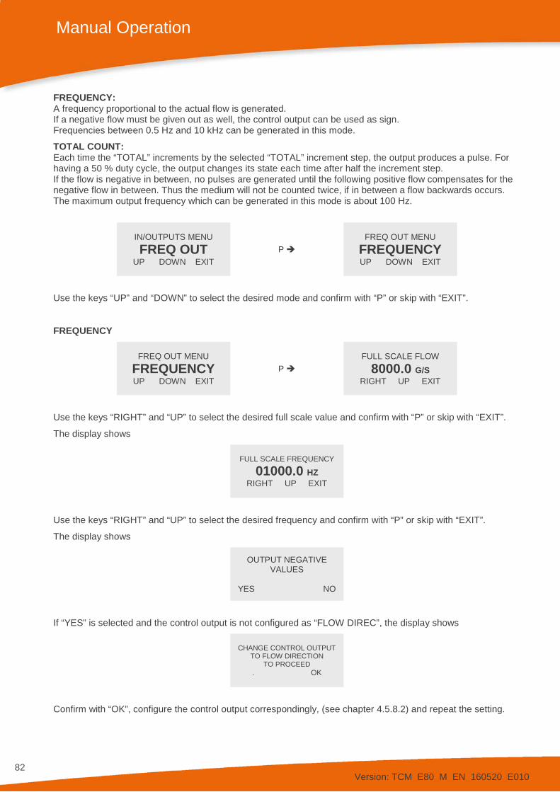
Version: TCM_E80_M_EN_160520_E010
82
Manual Operation
FREQUENCY: A frequency proportional to the actual flow is generated. If a negative flow must be given out as well, the control output can be used as sign. Frequencies between 0.5 Hz and 10 kHz can be generated in this mode.
TOTAL COUNT: Each time the “TOTAL” increments by the selected “TOTAL” increment step, the output produces a pulse. For having a 50 % duty cycle, the output changes its state each time after half the increment step. If the flow is negative in between, no pulses are generated until the following positive flow compensates for the negative flow in between. Thus the medium will not be counted twice, if in between a flow backwards occurs. The maximum output frequency which can be generated in this mode is about 100 Hz.
IN/OUTPUTS MENU FREQ OUT
UP DOWN EXIT P
FREQ OUT MENU FREQUENCY UP DOWN EXIT
Use the keys “UP” and “DOWN” to select the desired mode and confirm with “P” or skip with “EXIT”.
FREQUENCY
FREQ OUT MENU FREQUENCY UP DOWN EXIT
P FULL SCALE FLOW
8000.0 G/S RIGHT UP EXIT
Use the keys “RIGHT” and “UP” to select the desired full scale value and confirm with “P” or skip with “EXIT”.
The display shows
FULL SCALE FREQUENCY
01000.0 HZ RIGHT UP EXIT
Use the keys “RIGHT” and “UP” to select the desired frequency and confirm with “P” or skip with “EXIT”.
The display shows
OUTPUT NEGATIVE VALUES
YES NO
If “YES” is selected and the control output is not configured as “FLOW DIREC”, the display shows
CHANGE CONTROL OUTPUT
TO FLOW DIRECTION TO PROCEED
. OK
Confirm with “OK”, configure the control output correspondingly, (see chapter 4.5.8.2) and repeat the setting.

Version: TCM_E80_M_EN_160520_E010
83
Manual Operation
TOTAL COUNT
FREQ OUT MENU TOTAL COUNT
UP DOWN EXIT P
SELECT VALUE 0.10000 KG
RIGHT UP EXIT
Use the keys “RIGHT” and “UP” to select the desired step value and confirm with “P” or skip with “EXIT”.
4.5.8.2. CONTROL OUT Menu
In the submenu “CTRL OUT” the control output can be configured.
The control output has four operating modes:
FAULT: In case of an error the control output goes to the active state. “ACTIVE HIGH” means the output is low in normal operation, high in case of a fault. For setting the on and off delay time, please refer to chapter 4.5.6.8.
FLOW DIR: The flow direction is indicated. “ACTIVE HIGH“ means the output is high if a positive flow is measured.
BATCH: In the batch mode the TCE 8000 operates as a batch counter. If the preset batch value is reached, the control output goes to the active state. With an active signal at the control input the batch counter can be reset to zero. For this mode the control input must be configured as “RESET BATCH”. “ACTIVE HIGH” means the output goes to “HIGH“ when the preset batch value is reached.
FLOW LIMIT: If the actual flow becomes more positive than the “FLOW LIMIT“ plus hysteresis, the output goes to the active state. If the actual flow becomes more negative than the “FLOW LIMIT” minus hysteresis, the output goes to the inactive state. Between flow limit minus hysteresis and flow limit plus hysteresis, the output state does not change.
NOTE: For negative flow limits the relation is: -99 is greater than -100. “ACTIVE HIGH” means the output goes to “HIGH“ when the preset limit value is reached.
OFF: The output is deactivated. “ACTIVE HIGH“ means the output is permanently at high.
FREQUENCY: A frequency proportional to the current flow rate is generated. Frequencies between 0.5 Hz and 10 kHz can be generated in this mode.
DENS. LIMIT: When the measured density exceeds the value for DENS. LIMIT plus the hysteresis, the output enters the active state. When the density becomes less than DENS. LIMIT minus the hysteresis, the output enters the inactive state. The output does not change in between the two thresholds. PHASE SHIFT: Prerequisite: the FREQ-OUT has been programmed for TOTAL COUNT. As soon as “TOTAL” has increased by the chosen amount, another pulse is generated on FREQ OUT. To have a frequency ratio of 50% on the output, the state of the output changes respectively after half the amount. A pulse offset by 90° is also generated on CTRL OUT after each pulse on FREQ-OUT. The maximum output frequency in this operating mode is about 50 Hz.

Version: TCM_E80_M_EN_160520_E010
84
Manual Operation
FAULT
CTRL OUT MENU FAULT
UP DOWN EXIT P
SELECT ACTIVE STATE ACTIVE HIGH UP DOWN EXIT
Use the keys “UP” and “DOWN” to select the desired value and confirm with “P” or skip with “EXIT”.
The display returns to the “SETUP IN/OUTPUTS” menu.
FLOW DIR
CTRL OUT MENU FLOW DIR
UP DOWN EXIT P
SELECT ACTIVE STATE ACTIVE HIGH UP DOWN EXIT
Use the keys “UP” and “DOWN” to select the desired value and confirm with “P” or skip with “EXIT”.
The display returns to the “SETUP IN/OUTPUTS” menu.
BATCH
CTRL OUT MENU BATCH
UP DOWN EXIT P
BATCH VALUE 0.50000 KG
RIGHT UP EXIT
Use the keys “RIGHT” and “UP” to select the desired step value and confirm with “P” or skip with “EXIT”.
The display shows
SELECT ACTIVE STATE ACTIVE HIGH UP DOWN EXIT
Use the keys “UP” and “DOWN” to select the desired value and confirm with “P” or skip with “EXIT”.
The display returns to the “SETUP IN/OUTPUTS” menu.
FLOW LIMIT
CTRL OUT MENU FLOW LIMIT UP DOWN EXIT
P FLOW LIMIT VALUE 10.0000 KG/MIN RIGHT UP EXIT
Use the keys “RIGHT” and “UP” to select the desired step value and confirm with “P” or skip with “EXIT”.
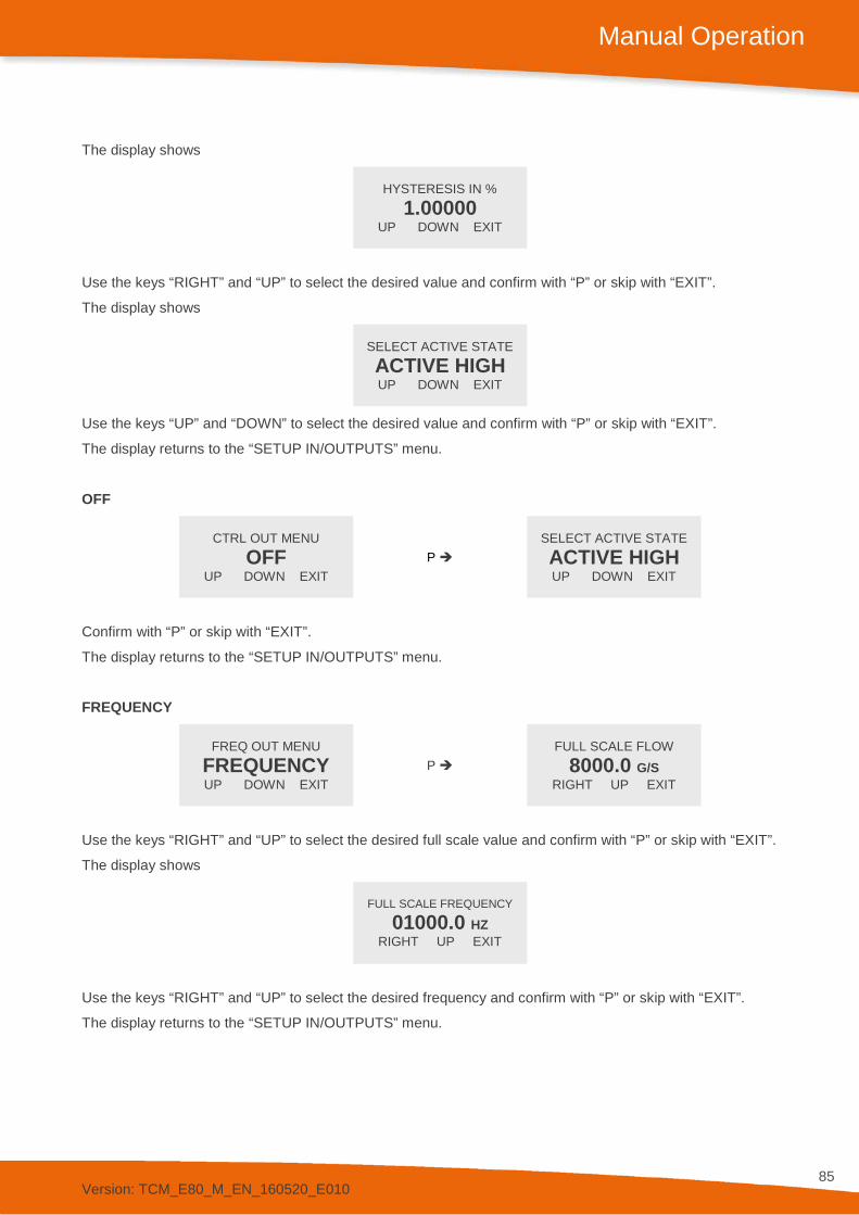
Version: TCM_E80_M_EN_160520_E010
85
Manual Operation
The display shows
HYSTERESIS IN %
1.00000 UP DOWN EXIT
Use the keys “RIGHT” and “UP” to select the desired value and confirm with “P” or skip with “EXIT”.
The display shows
SELECT ACTIVE STATE ACTIVE HIGH UP DOWN EXIT
Use the keys “UP” and “DOWN” to select the desired value and confirm with “P” or skip with “EXIT”.
The display returns to the “SETUP IN/OUTPUTS” menu.
OFF
CTRL OUT MENU OFF
UP DOWN EXIT P
SELECT ACTIVE STATE ACTIVE HIGH UP DOWN EXIT
Confirm with “P” or skip with “EXIT”.
The display returns to the “SETUP IN/OUTPUTS” menu.
FREQUENCY
FREQ OUT MENU FREQUENCY UP DOWN EXIT
P FULL SCALE FLOW
8000.0 G/S RIGHT UP EXIT
Use the keys “RIGHT” and “UP” to select the desired full scale value and confirm with “P” or skip with “EXIT”.
The display shows
FULL SCALE FREQUENCY
01000.0 HZ RIGHT UP EXIT
Use the keys “RIGHT” and “UP” to select the desired frequency and confirm with “P” or skip with “EXIT”.
The display returns to the “SETUP IN/OUTPUTS” menu.
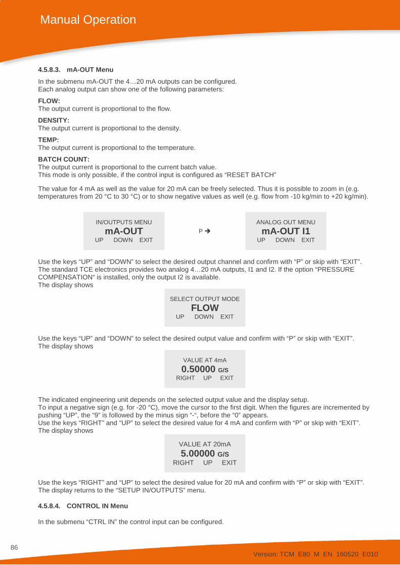
Version: TCM_E80_M_EN_160520_E010
86
Manual Operation
4.5.8.3. mA-OUT Menu In the submenu mA-OUT the 4…20 mA outputs can be configured. Each analog output can show one of the following parameters:
FLOW: The output current is proportional to the flow.
DENSITY: The output current is proportional to the density.
TEMP: The output current is proportional to the temperature.
BATCH COUNT: The output current is proportional to the current batch value. This mode is only possible, if the control input is configured as “RESET BATCH” The value for 4 mA as well as the value for 20 mA can be freely selected. Thus it is possible to zoom in (e.g. temperatures from 20 °C to 30 °C) or to show negative values as well (e.g. flow from -10 kg/min to +20 kg/min).
IN/OUTPUTS MENU mA-OUT
UP DOWN EXIT P
ANALOG OUT MENU mA-OUT I1
UP DOWN EXIT
Use the keys “UP” and “DOWN” to select the desired output channel and confirm with “P” or skip with “EXIT”. The standard TCE electronics provides two analog 4…20 mA outputs, I1 and I2. If the option “PRESSURE COMPENSATION“ is installed, only the output I2 is available. The display shows
SELECT OUTPUT MODE
FLOW UP DOWN EXIT
Use the keys “UP” and “DOWN” to select the desired output value and confirm with “P” or skip with “EXIT”. The display shows
VALUE AT 4mA 0.50000 G/S
RIGHT UP EXIT
The indicated engineering unit depends on the selected output value and the display setup. To input a negative sign (e.g. for -20 °C), move the cursor to the first digit. When the figures are incremented by pushing “UP”, the “9” is followed by the minus sign “-“, before the “0” appears. Use the keys “RIGHT” and “UP” to select the desired value for 4 mA and confirm with “P” or skip with “EXIT”. The display shows
VALUE AT 20mA 5.00000 G/S
RIGHT UP EXIT
Use the keys “RIGHT” and “UP” to select the desired value for 20 mA and confirm with “P” or skip with “EXIT”. The display returns to the “SETUP IN/OUTPUTS” menu.
4.5.8.4. CONTROL IN Menu
In the submenu “CTRL IN” the control input can be configured.

Version: TCM_E80_M_EN_160520_E010
87
Manual Operation
The control input has three operating modes:
EXT. ZERO: If an “ACTIVE” level is applied to the input, the TCE 8000 starts the zero offset adjustment procedure.
RESET BATCH: If an “ACTIVE” level is applied to the input, the batch counter is reset to 0. This mode must be selected, if the control output is to be used as a “BATCH-LIMIT” and/or if one of the analog outputs is to be used as batch output.
OFF: The input is deactivated. Changes of the level applied to the input have no effect. This is the default.
The “ACTIVE” level is freely selectable. Since the standard version of TCE has an internal pull-down resistor built in, the default is “ACTIVE HIGH”.
HOLD: If an “ACTIVE” level is applied to the input, the batch and grand totals stop counting.
IN/OUTPUTS MENU CTRL IN
UP DOWN EXIT P
CONTROL IN MENU EXT. ZERO
UP DOWN EXIT
Use the keys “UP” and “DOWN” to select the desired mode and confirm with “P” or skip with “EXIT”.
If “EXT. ZERO” or OFF is selected and one of the outputs is set to batch output, the display shows
CHANGE CTRL OUT MODE
TO SELECT THIS
. OK
Confirm with “OK” and configure the output correspondingly if required.
The display shows
SELECT ACTIVE STATE ACTIVE HIGH UP DOWN EXIT
Use the keys “UP” and “DOWN” to select the desired value and confirm with “P” or skip with “EXIT”.
The display returns to the “SETUP IN/OUTPUTS” menu.
4.5.8.5. mA-IN I1 Menu
In the submenu “mA-IN I1” the 4…20 mA input can be configured. This menu is only visible with the option “PRESSURE COMPENSATION“.
The value for 4 mA as well as the value for 20 mA can be freely selected to adapt the input to any passive 4…20 mA pressure sensor.
IN/OUTPUTS MENU mA-IN I1
UP DOWN EXIT P
ANALOG IN MENU PRESSURE
RIGHT UP EXIT

Version: TCM_E80_M_EN_160520_E010
88
Manual Operation
Use the keys “UP” and “DOWN” to select “OFF” or “PRESSURE” and confirm with “P” or skip with “EXIT”.
If “OFF” is selected, neither a pressure value is shown nor a pressure compensation using a measured pressure value is possible.
If “PRESSURE” was selected the display shows
VALUE AT 4mA 0.00 MPA
RIGHT UP EXIT
The indicated engineering unit depends on the selected output value and the display setup.
Use the keys “RIGHT” and “UP” to select the desired value for 4 mA and confirm with “P” or skip with “EXIT”.
The display shows
VALUE AT 20mA 10.00 MPA
RIGHT UP EXIT
Use the keys “RIGHT” and “UP” to select the desired value for 20 mA and confirm with “P” or skip with “EXIT”.
The display returns to the “SETUP IN/OUTPUTS” menu.
4.5.8.6. INTERFACE Menu
In the submenu “INTERFACE” the interface can be configured.
Depending on the configuration one or more of the following interfaces can be selected:
RS485 HART® Foundation Fieldbus®
IN/OUTPUTS MENU INTERFACE
UP DOWN EXIT P
SET INTERFACE MODE RS485
UP DOWN EXIT
Use the keys “UP” and “DOWN” to select the desired mode and confirm with “P” or skip with “EXIT”.
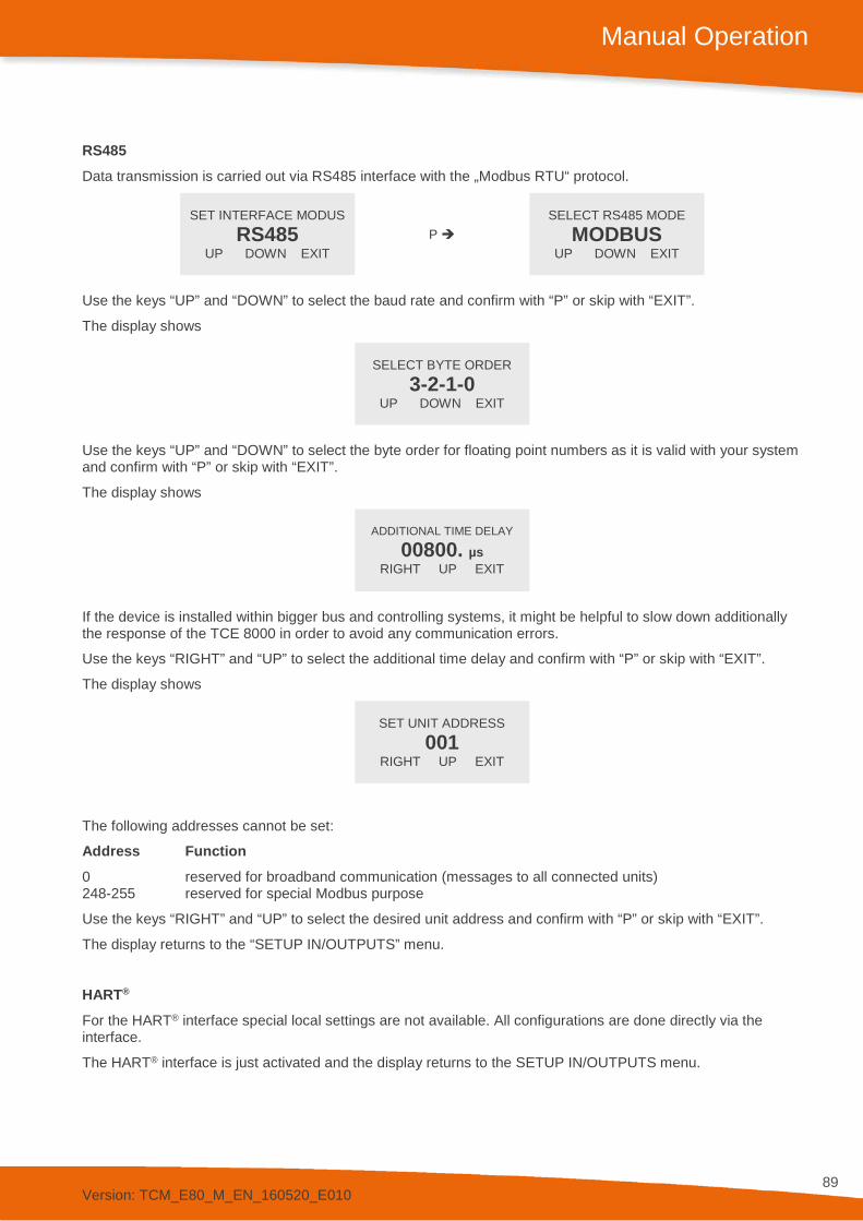
Version: TCM_E80_M_EN_160520_E010
89
Manual Operation
RS485 Data transmission is carried out via RS485 interface with the „Modbus RTU“ protocol.
SET INTERFACE MODUS RS485
UP DOWN EXIT P
SELECT RS485 MODE MODBUS
UP DOWN EXIT
Use the keys “UP” and “DOWN” to select the baud rate and confirm with “P” or skip with “EXIT”.
The display shows
SELECT BYTE ORDER
3-2-1-0 UP DOWN EXIT
Use the keys “UP” and “DOWN” to select the byte order for floating point numbers as it is valid with your system and confirm with “P” or skip with “EXIT”.
The display shows
ADDITIONAL TIME DELAY
00800. µs RIGHT UP EXIT
If the device is installed within bigger bus and controlling systems, it might be helpful to slow down additionally the response of the TCE 8000 in order to avoid any communication errors.
Use the keys “RIGHT” and “UP” to select the additional time delay and confirm with “P” or skip with “EXIT”.
The display shows
SET UNIT ADDRESS
001 RIGHT UP EXIT
The following addresses cannot be set:
Address Function 0 reserved for broadband communication (messages to all connected units) 248-255 reserved for special Modbus purpose
Use the keys “RIGHT” and “UP” to select the desired unit address and confirm with “P” or skip with “EXIT”.
The display returns to the “SETUP IN/OUTPUTS” menu.
HART® For the HART® interface special local settings are not available. All configurations are done directly via the interface.
The HART® interface is just activated and the display returns to the SETUP IN/OUTPUTS menu.

Version: TCM_E80_M_EN_160520_E010
90
Manual Operation
Foundation Fieldbus® For the Foundation Fieldbus® interface special local settings are not available. All configurations are done directly via the interface.
The Foundation Fieldbus® interface is just activated and the display returns to the “SETUP IN/OUTPUTS” menu.
4.5.9. SETUP DATA CONFIGURATION Menu
In the submenu “SETUP DATA CONFIG” the current settings can be stored to the backup memory and the stored settings can be recalled
SETUP MENU DATA CONFIG
UP DOWN EXIT P
DATA CONFIG MENU SAVE DATA
UP DOWN EXIT
Use the keys “UP” and “DOWN” to select the desired submenu and confirm with “P” or skip with “EXIT”.
4.5.9.1. SAVE DATA Menu
In the submenu “SAVE DATA” the current settings can be stored in the backup memory.
At each power on the TCE 8000 compares the content of the setup memory and the backup memory. If the data in those two memories are different, the TCE 8000 gives out a warning. To avoid this warning, it is recommended to make a backup as soon as the new settings are proven to be okay.
DATA CONFIG MENU SAVE DATA
UP DOWN EXIT P
READY TO SAVE DATA
START EXIT
Start the backup process with “START” or skip with “EXIT”.
If “START” is pressed, the display shows for some seconds
MEMORY ACCESS
After that for about two seconds
READY
The display returns to the “DATA CONFIG” menu.
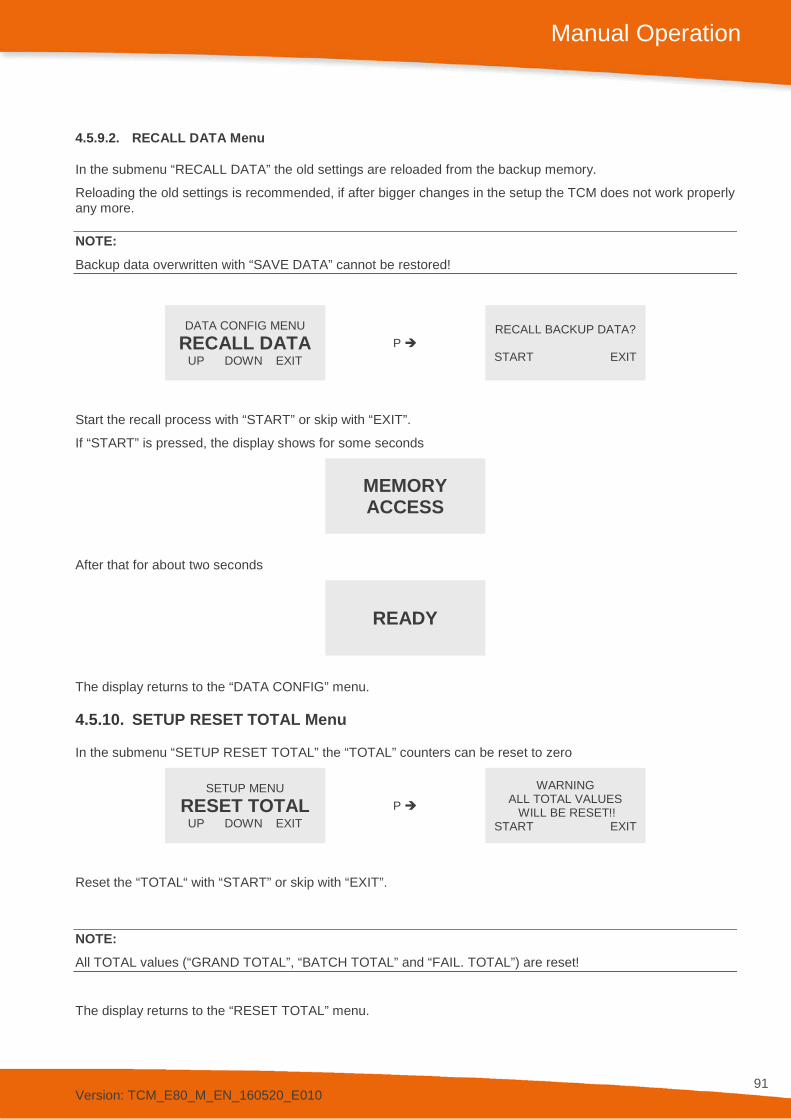
Version: TCM_E80_M_EN_160520_E010
91
Manual Operation
4.5.9.2. RECALL DATA Menu
In the submenu “RECALL DATA” the old settings are reloaded from the backup memory.
Reloading the old settings is recommended, if after bigger changes in the setup the TCM does not work properly any more.
NOTE: Backup data overwritten with “SAVE DATA” cannot be restored!
DATA CONFIG MENU RECALL DATA
UP DOWN EXIT P
RECALL BACKUP DATA?
START EXIT
Start the recall process with “START” or skip with “EXIT”.
If “START” is pressed, the display shows for some seconds
MEMORY ACCESS
After that for about two seconds
READY
The display returns to the “DATA CONFIG” menu.
4.5.10. SETUP RESET TOTAL Menu
In the submenu “SETUP RESET TOTAL” the “TOTAL” counters can be reset to zero
SETUP MENU RESET TOTAL
UP DOWN EXIT P
WARNING ALL TOTAL VALUES
WILL BE RESET!! START EXIT
Reset the “TOTAL“ with “START” or skip with “EXIT”.
NOTE: All TOTAL values (“GRAND TOTAL”, “BATCH TOTAL” and “FAIL. TOTAL”) are reset!
The display returns to the “RESET TOTAL” menu.
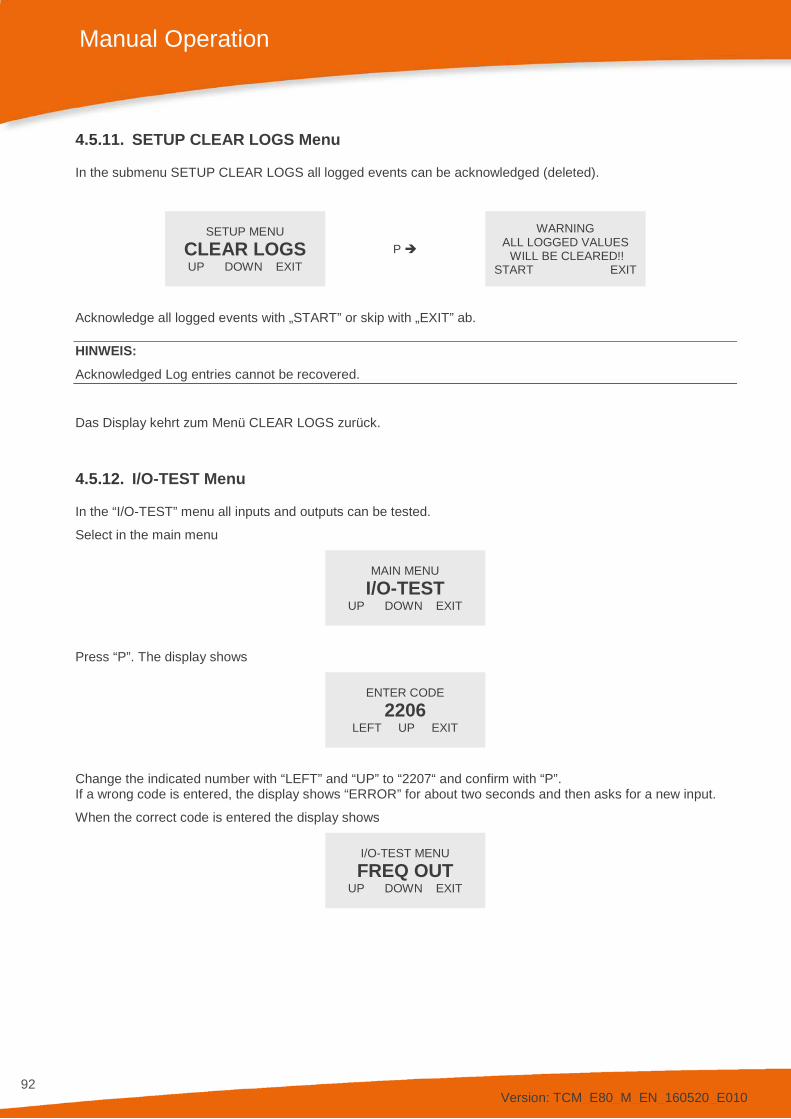
Version: TCM_E80_M_EN_160520_E010
92
Manual Operation
4.5.11. SETUP CLEAR LOGS Menu
In the submenu SETUP CLEAR LOGS all logged events can be acknowledged (deleted).
SETUP MENU CLEAR LOGS UP DOWN EXIT
P
WARNING ALL LOGGED VALUES WILL BE CLEARED!!
START EXIT
Acknowledge all logged events with „START” or skip with „EXIT” ab.
HINWEIS: Acknowledged Log entries cannot be recovered.
Das Display kehrt zum Menü CLEAR LOGS zurück.
4.5.12. I/O-TEST Menu
In the “I/O-TEST” menu all inputs and outputs can be tested.
Select in the main menu
MAIN MENU I/O-TEST
UP DOWN EXIT
Press “P”. The display shows
ENTER CODE
2206 LEFT UP EXIT
Change the indicated number with “LEFT” and “UP” to “2207“ and confirm with “P”. If a wrong code is entered, the display shows “ERROR” for about two seconds and then asks for a new input.
When the correct code is entered the display shows
I/O-TEST MENU FREQ OUT
UP DOWN EXIT
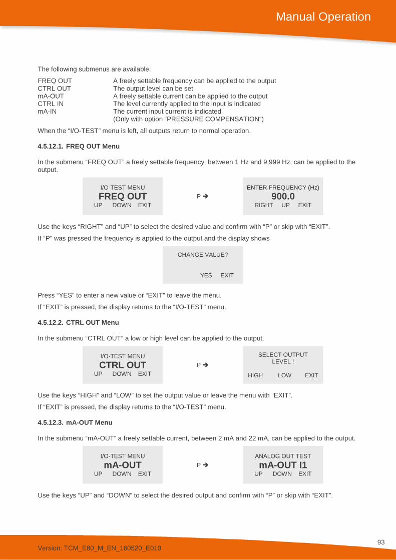
Version: TCM_E80_M_EN_160520_E010
93
Manual Operation
The following submenus are available:
FREQ OUT A freely settable frequency can be applied to the output CTRL OUT The output level can be set mA-OUT A freely settable current can be applied to the output CTRL IN The level currently applied to the input is indicated mA-IN The current input current is indicated (Only with option “PRESSURE COMPENSATION“)
When the “I/O-TEST” menu is left, all outputs return to normal operation.
4.5.12.1. FREQ OUT Menu
In the submenu “FREQ OUT” a freely settable frequency, between 1 Hz and 9,999 Hz, can be applied to the output.
I/O-TEST MENU FREQ OUT
UP DOWN EXIT P
ENTER FREQUENCY (Hz) 900.0
RIGHT UP EXIT
Use the keys “RIGHT” and “UP” to select the desired value and confirm with “P” or skip with “EXIT”.
If “P” was pressed the frequency is applied to the output and the display shows
CHANGE VALUE?
YES EXIT
Press “YES” to enter a new value or “EXIT” to leave the menu.
If “EXIT” is pressed, the display returns to the “I/O-TEST” menu.
4.5.12.2. CTRL OUT Menu
In the submenu “CTRL OUT” a low or high level can be applied to the output.
I/O-TEST MENU CTRL OUT
UP DOWN EXIT P
SELECT OUTPUT LEVEL !
HIGH LOW EXIT
Use the keys “HIGH” and “LOW” to set the output value or leave the menu with “EXIT”.
If “EXIT” is pressed, the display returns to the “I/O-TEST” menu.
4.5.12.3. mA-OUT Menu
In the submenu “mA-OUT” a freely settable current, between 2 mA and 22 mA, can be applied to the output.
I/O-TEST MENU mA-OUT
UP DOWN EXIT P
ANALOG OUT TEST mA-OUT I1
UP DOWN EXIT
Use the keys “UP” and “DOWN” to select the desired output and confirm with “P” or skip with “EXIT”.

Version: TCM_E80_M_EN_160520_E010
94
Manual Operation
The display shows
ENTER CURRENT 1 (mA)
00.0 RIGHT UP EXIT
Use the keys “RIGHT” and “UP” to select the desired value and confirm with “P” or skip with “EXIT”.
If “P” was pressed the current is applied to the output and the display shows
CHANGE VALUE?
YES EXIT
Press “YES” to enter a new value or “EXIT” to leave the menu.
If “EXIT” is pressed, the display returns to the “I/O-TEST” menu.
4.5.12.4. CTRL IN Menu
In the submenu “CTRL IN” the display shows the level currently applied to the control input.
I/O-TEST MENU CTRL IN
UP DOWN EXIT P
CURRENT CTRL-IN LEVEL: LOW
. EXIT
The display shows the actual level at the input. It is automatically updated when the level at the input has changed.
After evaluating the input, press “EXIT” to return to the “I/O-TEST” menu.
4.5.12.5. mA-IN Menu (optional)
The submenu “mA-IN” is only selectable with the option “PRESSURE COMPENSATION“.
In the submenu mA-IN the display shows the current applied to the control input.
I/O-TEST MENU mA-IN
UP DOWN EXIT P
INPUT CURRENT 00.0 mA
. EXIT
After evaluating the input, press “EXIT” to return to the “I/O-TEST” menu.
4.5.13. SERVICE Menu
The “SERVICE” menu is used to calibrate the meter, to set a user password and to recall the original factory settings.
For a description of the menu, please refer to chapter 6.
Version: TCM_E80_M_EN_160520_E010
95
Remote Operation
5. Remote Operation
As a standard, the TCE 8000 is equipped with RS485 and HART® interfaces. Foundation Fieldbus® is also available as an option.
Please read chapter 4 before installing a remote control, for getting a description of the functionality.
5.1. Serial RS485 Interface 5.1.1. Electrical Connection of RS485 Interface
Prepare the TCE 8000 and the cable as described in chapter 3.3.
Connect the signal RS485A or RS485+ (both names are used in the literature) to terminal 22 and RS485- or RS485B to terminal 21.
Terminal 20 is the ground reference pin for the interface and is connected to GND (terminal 8) with the non- Ex versions and connected to PE (terminal 52) with the Ex versions.
NOTE: The operating range of the data terminals (21 and 22) is -7 V to +12 V referred to the reference pin (20). Voltages outside that range could damage the TCE 8000.
5.1.2. Usage of the TRICOR Configurator
The control software TRICOR Configurator as well as the corresponding manual is provided for download at the “Download” area of the TRICOR webpage (www.tricorflow.com).
Using the TRICOR Configurator a remote operation with TRICOR meters is possible, without the need of knowledge about the Modbus protocol.
The usage of the converter CON.USB.RS-ISO is recommended for the connection between the TCE electronics and a personal computer (via USB interface).
5.1.3. RS485-Interface-Protocol
For communication via RS485 the Modbus RTU protocol is used.
A detailed description of the Modbus frame structure and the implemented registers and addresses can be found at the “Download” area of the TRICOR webpage (www.tricorflow.com).
Version: TCM_E80_M_EN_160520_E010
96
Remote Operation
5.2. HART® 5.2.1. Electrical Connection for HART®
For the HART® communication the current output CURRENT 2 (I2) is used.
Connect the analog output CURRENT 2 as described in chapter 3.3.6 and connect a HART® communicator or a HART® Handheld Terminal in series to the analog output of the TCE.
Refer to the manual of your HART® communicator, respectively of the HART® Handheld Terminal, for the proper connection.
5.2.2. Device Description File for HART® Interface Protocol
For getting the newest DD file for the HART® Interface, please contact your TRICOR representative.
5.3. Foundation Fieldbus® 5.3.1. Electrical Connection for Foundation Fieldbus®
Prepare the TCE 8000 and the cable as described in chapter 3.3.2 or 3.3.3.
Connect the signal FF+ (positive rail of the bus) to terminal 32 and FF- (negative rail of the bus) to terminal 31.
5.3.2. Device Description File for Foundation Fieldbus® Interface Protocol
For getting the newest DD file for the Foundation Fieldbus® Interface, please contact TRICOR representative.
Version: TCM_E80_M_EN_160520_E010
97
Service and Maintenance
6. Service and Maintenance
6.1. Maintenance The TRICOR Mass Flow Meters do not require regular maintenance.
In case of abrasive or sedimenting media however, it is recommended to return the measuring system to the manufacturer after 8,000 hours of operation for re-calibration and pressure test. This interval may be shorter when the medium is extremely abrasive or sedimenting. For best performance we recommend checking the calibration every 5 years, in harsh environments even more frequently.
If for the specific application an obligatory calibration is required, refer to the corresponding national regulations for the necessary calibration intervals.
6.2. Trouble Shooting In case the TRICOR Mass Flow Meter does not work properly, first check the following items:
No display, no LED lighting All cables properly connected? Connect the missing cables Power supply switched on? Switch on the power supply Display positioned properly (compact and wall mount only)? Remove the display and reset it properly Internal fuse of the TCE blown? For checking and changing the fuses refer to chapter 6.3.
Output frequency too high or unstable Most probably EMC problems Shield and ground properly connected? Connect shield properly. If necessary, try additional means of grounding and shielding
Unstable flow reading with (theoretically) stable flow Gas bubbles or solid particles in the medium? Mount the meter with the correct orientation Strong external vibrations? Decouple the meter from the vibration source Flow or pressure slugs in the medium? Decouple the meter hydraulically
No frequency or current output with operating display Output correctly wired? Correct the wiring (see chapter 2.3) Output correctly configured? Correct the configuration (see chapter 4.5.8.1) Wrong flow direction (Flow in the display is negative)? Change flow direction (see chapter 4.5.6.6)
Pressure display shows “PRESS ERROR” Input correctly wired? Correct the wiring (see chapter 2.3) Sensor working normally? Check with external digital Ampere meter. If required, replace the sensor
No pressure compensation Compensation enabled? Enable compensation (see chapter 4.5.6.9) Sensor working normally? Check with external digital Ampere meter. If required, replace the sensor

Version: TCM_E80_M_EN_160520_E010
98
Service and Maintenance
6.3. Changing the Fuses The power supply inputs of the TCE 8000 contain fuses.
With the non-Ex versions the fuses can easily be replaced by qualified personnel.
6.3.1. Changing the fuse with the TCE 8***-wall mounted-**** and compact version
Switch off the power supply.
Open the safety screw at the display cover of the unit with the provided Allen key.
Remove the display cover of the TCE by turning it counter clockwise.
Pull out the display
Remove the 3 screws in the PCB and pull it out carefully.
Below the ribbon cable connector you find the following fuse in the fuse holder:
Littelfuse NANO 2 375mA slow blow, ordering code 0452.375
NOTE: For your own safety replace the fuse only by the same type and rating.
Replace the fuse and reclose the unit.
6.3.2. Changing the fuse with the TCE 8***-S-****
Switch off the power supply.
Remove the 4 screws in the back panel and pull out the back panel carefully.
Below the ribbon cable connector you find the following fuse in the fuse holder:
Littelfuse NANO 2 375mA slow blow, ordering code 0452.375
NOTE: For your own safety replace the fuse only by the same type and rating.
Replace the fuse and reclose the unit.
6.3.3. Changing the fuses with the Ex versions
With the Ex versions the fuses are part of the safety barriers and must only be exchanged by KEM/AWL or by personnel authorized by KEM/AWL.
In case one of the fuses has blown, contact KEM/AWL or your nearest dealer.
WARNING! The Ex versions of the TCE 8000 series contain several internal fuses for protecting the intrinsically safe TCM against too high voltage and power. Those fuses are critical parts and must not be exchanged except by KEM/AWL or by service personnel authorized by KEM/AWL. If the fuses are replaced by third persons, the Ex certification for the TCM will be void!
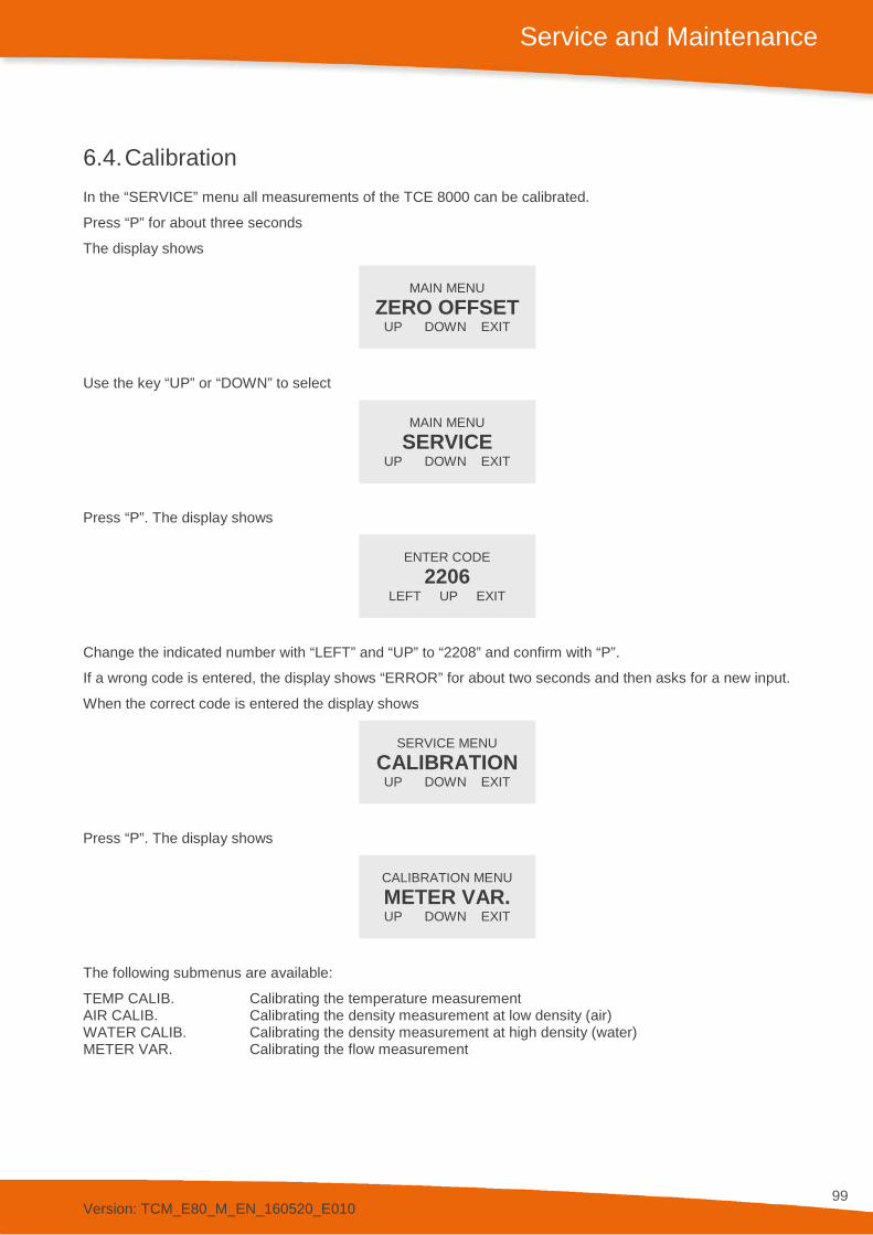
Version: TCM_E80_M_EN_160520_E010
99
Service and Maintenance
6.4. Calibration In the “SERVICE” menu all measurements of the TCE 8000 can be calibrated.
Press “P” for about three seconds
The display shows
MAIN MENU
ZERO OFFSET UP DOWN EXIT
Use the key “UP” or “DOWN” to select
MAIN MENU
SERVICE UP DOWN EXIT
Press “P”. The display shows
ENTER CODE
2206 LEFT UP EXIT
Change the indicated number with “LEFT” and “UP” to “2208” and confirm with “P”.
If a wrong code is entered, the display shows “ERROR” for about two seconds and then asks for a new input.
When the correct code is entered the display shows
SERVICE MENU
CALIBRATION UP DOWN EXIT
Press “P”. The display shows
CALIBRATION MENU METER VAR. UP DOWN EXIT
The following submenus are available:
TEMP CALIB. Calibrating the temperature measurement AIR CALIB. Calibrating the density measurement at low density (air) WATER CALIB. Calibrating the density measurement at high density (water) METER VAR. Calibrating the flow measurement
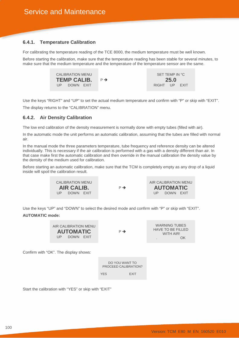
Version: TCM_E80_M_EN_160520_E010
100
Service and Maintenance
6.4.1. Temperature Calibration
For calibrating the temperature reading of the TCE 8000, the medium temperature must be well known.
Before starting the calibration, make sure that the temperature reading has been stable for several minutes, to make sure that the medium temperature and the temperature of the temperature sensor are the same.
CALIBRATION MENU TEMP CALIB. UP DOWN EXIT
P SET TEMP IN °C
25.0 RIGHT UP EXIT
Use the keys “RIGHT” and “UP” to set the actual medium temperature and confirm with “P” or skip with “EXIT”.
The display returns to the “CALIBRATION” menu.
6.4.2. Air Density Calibration
The low end calibration of the density measurement is normally done with empty tubes (filled with air).
In the automatic mode the unit performs an automatic calibration, assuming that the tubes are filled with normal air.
In the manual mode the three parameters temperature, tube frequency and reference density can be altered individually. This is necessary if the air calibration is performed with a gas with a density different than air. In that case make first the automatic calibration and then override in the manual calibration the density value by the density of the medium used for calibration.
Before starting an automatic calibration, make sure that the TCM is completely empty as any drop of a liquid inside will spoil the calibration result.
CALIBRATION MENU AIR CALIB.
UP DOWN EXIT P
AIR CALIBRATION MENU AUTOMATIC UP DOWN EXIT
Use the keys “UP” and “DOWN” to select the desired mode and confirm with “P” or skip with “EXIT”.
AUTOMATIC mode:
AIR CALIBRATION MENU AUTOMATIC UP DOWN EXIT
P
WARNING TUBES HAVE TO BE FILLED
WITH AIR! . OK
Confirm with “OK”. The display shows:
DO YOU WANT TO
PROCEED CALIBRATION?
YES EXIT
Start the calibration with “YES” or skip with “EXIT”

Version: TCM_E80_M_EN_160520_E010
101
Service and Maintenance
If “YES” was pressed, the display shows:
AIR TEMP: 23.0°C FREQUENCY: 141.4 HZ DENSITY: 1.4 G/L
OK
Confirm with “OK”. The display returns to the “AIR CALIBRATION“ menu.
MANUAL mode:
AIR CALIBRATION MENU MANUAL
UP DOWN EXIT P
ENTER AIR TEMP: 23.0 °C
RIGHT UP EXIT
Use the keys “RIGHT” and “UP” to set the reference temperature and confirm with “P” or skip with “EXIT”. The display shows:
ENTER AIR FREQ:
141.52 Hz RIGHT UP EXIT
This value must only be entered, if you have the data from a calibration sheet of the TCM. Skip with “EXIT”. The display shows
ENTER AIR DENSITY:
1.407 G/L RIGHT UP EXIT
Use the keys “RIGHT” and “UP” to set the reference density and confirm with “P” or skip with “EXIT”.
The display returns to the “AIR CALIBRATION” menu.
6.4.3. Water Density Calibration
The high end calibration of the density measurement is normally done tubes filled with water. Butanol or other liquids with well-known density can be used as well.
In the automatic mode the unit performs an automatic calibration, assuming that the tubes are filled with water.
In the manual mode the three parameters temperature, tube frequency and reference density can be altered individually. This is necessary if the water calibration is performed with a liquid with a density different than water. In that case make first the automatic calibration and then override in the manual calibration the density value by the density of the medium used for calibration.
Before starting an automatic calibration, make sure that the TCM is completely filled with the reference medium. Any pollution (air bubbles, solid particles or rests of other liquids) will spoil the calibration result.
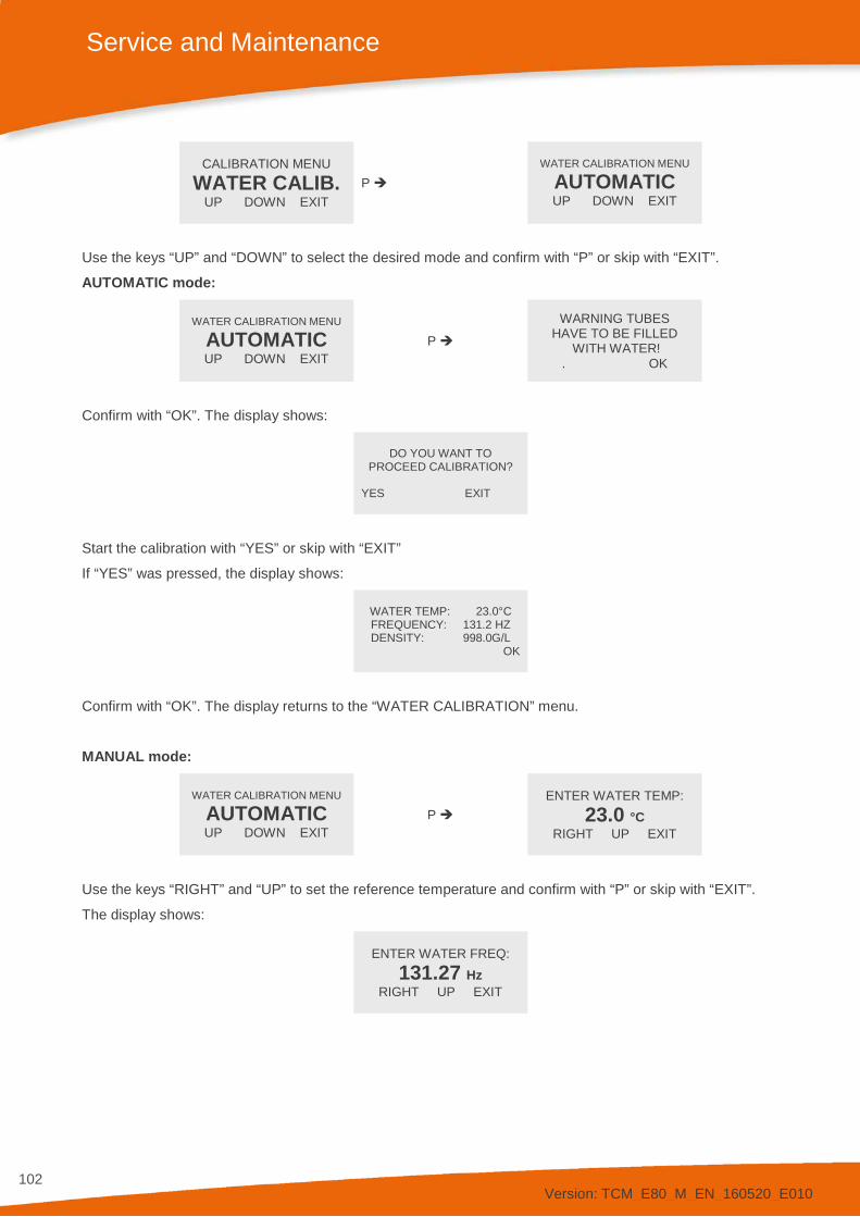
Version: TCM_E80_M_EN_160520_E010
102
Service and Maintenance
CALIBRATION MENU WATER CALIB.
UP DOWN EXIT P
WATER CALIBRATION MENU
AUTOMATIC UP DOWN EXIT
Use the keys “UP” and “DOWN” to select the desired mode and confirm with “P” or skip with “EXIT”.
AUTOMATIC mode:
WATER CALIBRATION MENU
AUTOMATIC UP DOWN EXIT
P
WARNING TUBES HAVE TO BE FILLED
WITH WATER! . OK
Confirm with “OK”. The display shows:
DO YOU WANT TO
PROCEED CALIBRATION?
YES EXIT
Start the calibration with “YES” or skip with “EXIT”
If “YES” was pressed, the display shows:
WATER TEMP: 23.0°C FREQUENCY: 131.2 HZ DENSITY: 998.0G/L
OK
Confirm with “OK”. The display returns to the “WATER CALIBRATION” menu.
MANUAL mode:
WATER CALIBRATION MENU
AUTOMATIC UP DOWN EXIT
P ENTER WATER TEMP:
23.0 °C RIGHT UP EXIT
Use the keys “RIGHT” and “UP” to set the reference temperature and confirm with “P” or skip with “EXIT”.
The display shows:
ENTER WATER FREQ:
131.27 Hz RIGHT UP EXIT
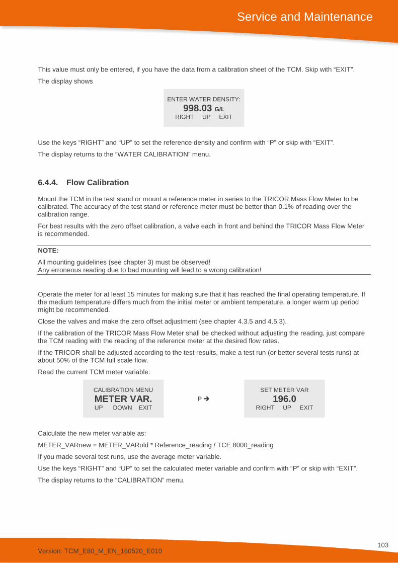
Version: TCM_E80_M_EN_160520_E010
103
Service and Maintenance
This value must only be entered, if you have the data from a calibration sheet of the TCM. Skip with “EXIT”.
The display shows
ENTER WATER DENSITY:
998.03 G/L RIGHT UP EXIT
Use the keys “RIGHT” and “UP” to set the reference density and confirm with “P” or skip with “EXIT”.
The display returns to the “WATER CALIBRATION” menu.
6.4.4. Flow Calibration
Mount the TCM in the test stand or mount a reference meter in series to the TRICOR Mass Flow Meter to be calibrated. The accuracy of the test stand or reference meter must be better than 0.1% of reading over the calibration range.
For best results with the zero offset calibration, a valve each in front and behind the TRICOR Mass Flow Meter is recommended.
NOTE: All mounting guidelines (see chapter 3) must be observed! Any erroneous reading due to bad mounting will lead to a wrong calibration!
Operate the meter for at least 15 minutes for making sure that it has reached the final operating temperature. If the medium temperature differs much from the initial meter or ambient temperature, a longer warm up period might be recommended.
Close the valves and make the zero offset adjustment (see chapter 4.3.5 and 4.5.3).
If the calibration of the TRICOR Mass Flow Meter shall be checked without adjusting the reading, just compare the TCM reading with the reading of the reference meter at the desired flow rates.
If the TRICOR shall be adjusted according to the test results, make a test run (or better several tests runs) at about 50% of the TCM full scale flow.
Read the current TCM meter variable:
CALIBRATION MENU METER VAR. UP DOWN EXIT
P SET METER VAR
196.0 RIGHT UP EXIT
Calculate the new meter variable as:
METER_VARnew = METER_VARold * Reference_reading / TCE 8000_reading
If you made several test runs, use the average meter variable.
Use the keys “RIGHT” and “UP” to set the calculated meter variable and confirm with “P” or skip with “EXIT”.
The display returns to the “CALIBRATION” menu.

Version: TCM_E80_M_EN_160520_E010
104
Service and Maintenance
6.5. Service Apart from the fuses the TCE 8000 does not contain any user serviceable parts.
In case of malfunction, please contact your nearest dealer or directly KEM Küppers Elektromechanik GmbH.
For the addresses see chapter 8.
6.6. Global Device Password In order to protect the TRICOR Mass Flow Meter from unauthorized access, a user-specific password can be set. It protects the access to all configuration menus. The password can be set either through the local display as described below or through the Modbus interface (see TCM_COMO_S_EN_150408_E003, TRICOR Modbus RTU manual).
NOTE: If the global access code gets lost, the meter must be returned to KEM/AWL for resetting it. Resetting the code onsite is not possible!
Press “P” for about three seconds. The display shows
MAIN MENU
ZERO OFFSET UP DOWN EXIT
Use the key “UP” or “DOWN” to select
MAIN MENU
SERVICE UP DOWN EXIT
Press “P”. The display shows
ENTER CODE
2206 LEFT UP EXIT
Change the indicated number with “LEFT” and “UP” to “2208” and confirm with “P”.
If a wrong code is entered, the display shows “ERROR” for about two seconds and then asks for a new input.
When the correct code is entered the display shows
SERVICE MENU CALIBRATION
UP DOWN EXIT
Use the key “UP” or “DOWN” to select ACCESS CODE and confirm with “P” or skip with “EXIT”

Version: TCM_E80_M_EN_160520_E010
105
Service and Maintenance
SERVICE MENU ACCESS CODE
UP DOWN EXIT P
SET P-ACCESS CODE 0001
LEFT UP EXIT
Change the indicated number with “LEFT” and “UP” to the desired code number and confirm with “P”.
The display shows
OLD P-CODE: 0 NEW P-CODE: ****
OK CANCEL
Confirm with “OK” or skip with “CANCEL”.
Write down the access code.
The display returns to the “ACCESS CODE” menu.
6.7. Reloading Factory Settings In case the TCM has been completely misadjusted for any reason, the TCM can be reset to the original settings ex works.
Press “P” for about three seconds. The display shows
MAIN MENU
ZERO OFFSET UP DOWN EXIT
Use the key “UP” or “DOWN” to select
MAIN MENU
SERVICE UP DOWN EXIT
Press “P”. The display shows
ENTER CODE
2206 LEFT UP EXIT
Change the indicated number with “LEFT” and “UP” to “2208” and confirm with “P”.
If a wrong code is entered, the display shows “ERROR” for about two seconds and then asks for a new input.
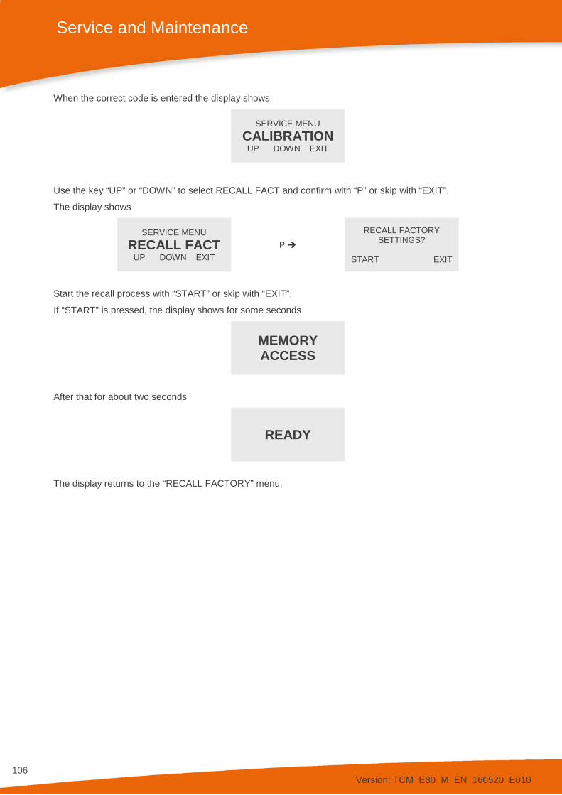
Version: TCM_E80_M_EN_160520_E010
106
Service and Maintenance
When the correct code is entered the display shows
SERVICE MENU
CALIBRATION UP DOWN EXIT
Use the key “UP” or “DOWN” to select RECALL FACT and confirm with “P” or skip with “EXIT”.
The display shows
SERVICE MENU RECALL FACT
UP DOWN EXIT P
RECALL FACTORY SETTINGS?
START EXIT
Start the recall process with “START” or skip with “EXIT”.
If “START” is pressed, the display shows for some seconds
MEMORY ACCESS
After that for about two seconds
READY
The display returns to the “RECALL FACTORY” menu.
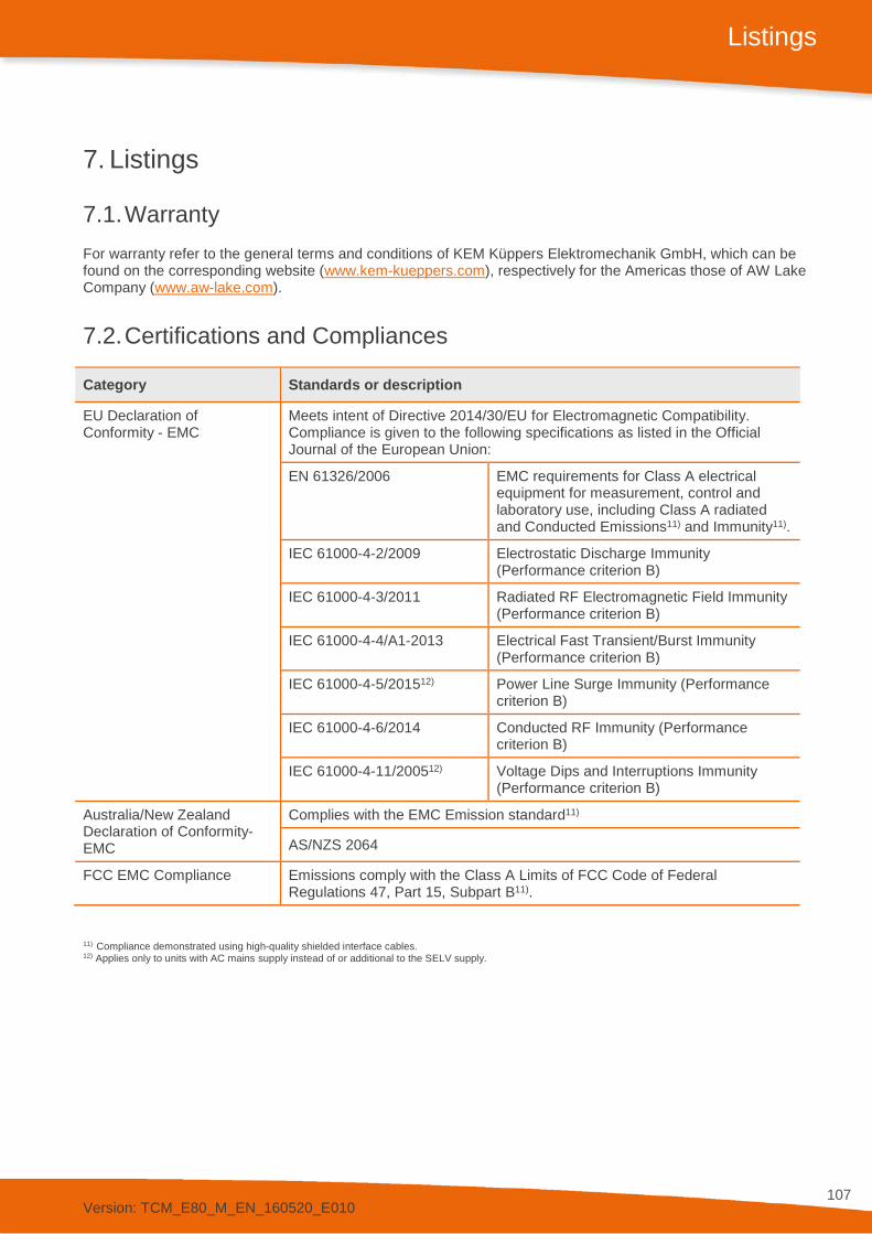
Version: TCM_E80_M_EN_160520_E010
107
Listings
7. Listings
7.1. Warranty For warranty refer to the general terms and conditions of KEM Küppers Elektromechanik GmbH, which can be found on the corresponding website (www.kem-kueppers.com), respectively for the Americas those of AW Lake Company (www.aw-lake.com).
7.2. Certifications and Compliances
Category Standards or description
EU Declaration of Conformity - EMC
Meets intent of Directive 2014/30/EU for Electromagnetic Compatibility. Compliance is given to the following specifications as listed in the Official Journal of the European Union:
EN 61326/2006 EMC requirements for Class A electrical equipment for measurement, control and laboratory use, including Class A radiated and Conducted Emissions11) and Immunity11).
IEC 61000-4-2/2009 Electrostatic Discharge Immunity (Performance criterion B)
IEC 61000-4-3/2011 Radiated RF Electromagnetic Field Immunity (Performance criterion B)
IEC 61000-4-4/A1-2013 Electrical Fast Transient/Burst Immunity (Performance criterion B)
IEC 61000-4-5/201512) Power Line Surge Immunity (Performance criterion B)
IEC 61000-4-6/2014 Conducted RF Immunity (Performance criterion B)
IEC 61000-4-11/200512) Voltage Dips and Interruptions Immunity (Performance criterion B)
Australia/New Zealand Declaration of Conformity- EMC
Complies with the EMC Emission standard11)
AS/NZS 2064
FCC EMC Compliance Emissions comply with the Class A Limits of FCC Code of Federal Regulations 47, Part 15, Subpart B11).
11) Compliance demonstrated using high-quality shielded interface cables. 12) Applies only to units with AC mains supply instead of or additional to the SELV supply.

Version: TCM_E80_M_EN_160520_E010
108
Listings
Category Standards or description
EU Declaration of Conformity – Low Voltage
Compliance is given to the following specification as listed in the Official Journal of the European Union: Low Voltage Directive 2014/35/EU EN 61010-1/2010 Safety requirements for electrical
equipment for measurement control and laboratory use.
Designed to meet the following US standards
UL 61010-1/2012 Standard for electrical measuring and test equipment.
Designed to meet the following Canadian standards
CAN/CSA C22.2 no. 61010-1-4/2008
Safety requirements for electrical equipment for measurement, control, and laboratory use.
International standards IEC61010-1/2010 Safety requirements for electrical equipment for measurement, control, and laboratory use.
Equipment Type Test and measuring Safety Class Class 1 (as defined in IEC 61010-1, Annex H) – grounded product ATEX IECEx
II 2G Ex d [ia] IIC T2…T4 Gb Ex d [ia] IIC T2…T4 Gb
TCE 800*-W(I)-****-Ex
II 2G Ex d [ia] IIC T2…T4 Gb Ex d [ia] IIC T2…T4 Gb
TCM 0325…7900-**-****-C***-Ex
II 2G Ex d [ia] IIB T2…T4 Gb Ex d [ia] IIB T2…T4 Gb
TCE 801*-W(I)-****-Ex
II 2G Ex d [ia] IIB T2…T4 Gb Ex d [ia] IIB T2…T4 Gb
TCM 028K…065K-**-****-C***-Ex
II (2)G [Ex ia Gb] IIC [Ex ia Gb] IIC
TCE 800*-L-****-Ex
II (2)G [Ex ia Gb] IIB [Ex ia Gb] IIB
TCE 801*-L-****-Ex
II 2G Ex ia IIC T2…T4 Gb Ex ia IIC T2…T4 Gb
TCM 0325…7900-*-****-****-Ex TCM 0325…7900-*-****-****-Ex3
II 2G Ex ia IIB T2…T4 Gb Ex ia IIB T2…T4 Gb
TCM 028K…230K-*-****-****-Ex (TCM 230K : only with remote electronics) TCM 028K…230K-*-****-****-Ex3
ATEX II 3G Ex nA IIC T2…T4 Gc TCE 800*-W-****-Exn TCM ****-*-****-****-Exn
cCSAus Class I, Division 1 Group A, B, C, D, T2…T4
TCE 800*-W-****-Ex1 TCE 800*-W-****-Ex3 TCE 800*-L-****-Ex1 TCM 0325…7900-*-****-****-Ex1
Class I, Division 1 Group A, B, C, D, T2…T4
TCM 0325…7900-**-****-C***-Ex1
Class I, Division 1 Group C, D, T2…T4
TCE 801*-W-****-Ex1 TCE 801*-W-****-Ex3 TCE 801*-L-****-Ex1 TCM 028K…230K-*-****-****-Ex1
Class I, Division 1 Group C, D, T2…T4
TCM 028K…230K-**-****-C***-Ex1 (TCM 230K: only with remote electronics)
Ex3: only with remote electronics. For Ex1 and Ex3 the electronic is only available in aluminum housing.
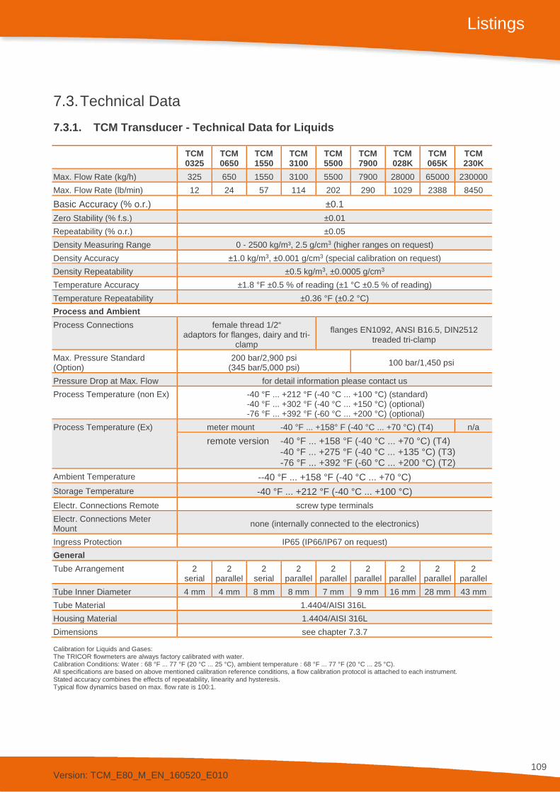
Version: TCM_E80_M_EN_160520_E010
109
Listings
7.3. Technical Data 7.3.1. TCM Transducer - Technical Data for Liquids
TCM 0325
TCM 0650
TCM 1550
TCM 3100
TCM 5500
TCM 7900
TCM 028K
TCM 065K
TCM 230K
Max. Flow Rate (kg/h) 325 650 1550 3100 5500 7900 28000 65000 230000 Max. Flow Rate (lb/min) 12 24 57 114 202 290 1029 2388 8450 Basic Accuracy (% o.r.) ±0.1 Zero Stability (% f.s.) ±0.01 Repeatability (% o.r.) ±0.05 Density Measuring Range 0 - 2500 kg/m³, 2.5 g/cm3 (higher ranges on request) Density Accuracy ±1.0 kg/m3, ±0.001 g/cm3 (special calibration on request) Density Repeatability ±0.5 kg/m3, ±0.0005 g/cm3 Temperature Accuracy ±1.8 °F ±0.5 % of reading (±1 °C ±0.5 % of reading) Temperature Repeatability ±0.36 °F (±0.2 °C) Process and Ambient Process Connections female thread 1/2“
adaptors for flanges, dairy and tri-clamp
flanges EN1092, ANSI B16.5, DIN2512 treaded tri-clamp
Max. Pressure Standard (Option)
200 bar/2,900 psi (345 bar/5,000 psi) 100 bar/1,450 psi
Pressure Drop at Max. Flow for detail information please contact us Process Temperature (non Ex) -40 °F ... +212 °F (-40 °C ... +100 °C) (standard)
-40 °F ... +302 °F (-40 °C ... +150 °C) (optional) -76 °F ... +392 °F (-60 °C ... +200 °C) (optional)
Process Temperature (Ex) meter mount -40 °F ... +158° F (-40 °C ... +70 °C) (T4) n/a remote version -40 °F ... +158 °F (-40 °C ... +70 °C) (T4) -40 °F ... +275 °F (-40 °C ... +135 °C) (T3) -76 °F ... +392 °F (-60 °C ... +200 °C) (T2)
Ambient Temperature --40 °F ... +158 °F (-40 °C ... +70 °C) Storage Temperature -40 °F ... +212 °F (-40 °C ... +100 °C) Electr. Connections Remote screw type terminals Electr. Connections Meter Mount none (internally connected to the electronics)
Ingress Protection IP65 (IP66/IP67 on request) General Tube Arrangement 2
serial 2
parallel 2
serial 2
parallel 2
parallel 2
parallel 2
parallel 2
parallel 2
parallel Tube Inner Diameter 4 mm 4 mm 8 mm 8 mm 7 mm 9 mm 16 mm 28 mm 43 mm Tube Material 1.4404/AISI 316L Housing Material 1.4404/AISI 316L Dimensions see chapter 7.3.7 Calibration for Liquids and Gases: The TRICOR flowmeters are always factory calibrated with water. Calibration Conditions: Water : 68 °F ... 77 °F (20 °C ... 25 °C), ambient temperature : 68 °F ... 77 °F (20 °C ... 25 °C). All specifications are based on above mentioned calibration reference conditions, a flow calibration protocol is attached to each instrument. Stated accuracy combines the effects of repeatability, linearity and hysteresis. Typical flow dynamics based on max. flow rate is 100:1.

Version: TCM_E80_M_EN_160520_E010
110
Listings
7.3.2. Accuracy for Liquids
Fig. 25: Accuracy for Liquids
Example for a TCM 0325: 325 kg/h * ZeroPoint (0.01 %) = 0.0325 kg/h 12 lb/min * 0.01 % = 0.0012 lb/min 325 kg/h * Basic Accuracy (0.1 %) = 0.325 kg/h 12 lb/min * 0.1 % = 0.012 lb/min Result: (0.0325 / 0.325) * 100 = 10 % (32.5 kg/h) (0.0012 / 0.012) * 100 = 10 % (1.2 lb/min)
All flow rates ≥ 10% or 32.5 kg/h (1.2 lb/min): Measured error = Basic Accuracy All flow rates < 10% or 32.5 kg/h (1.2 lb/min): Measured error = (Zero Point / Measured Value) * 100

Version: TCM_E80_M_EN_160520_E010
111
Listings
7.3.3. TCM Transducer - Technical Data for Gases
TCM 0325
TCM 0650
TCM 1550
TCM 3100
TCM 5500
TCM 7900
TCM 028K
TCM 065K
TCM 230K
Nom. Flow Rate (kg/h)13) 15) 78 177 333 740 910 1430 5100 15650 48900 Nom. Flow Rate (lb/min)13) 15) 3 7 12 27 34 53 188 575 1797 Nom. Flow Rate (Nm3/h)13) 14) 109 247 464 1031 1268 1993 7109 21813 68157 Nom. Flow Rate (SCFM)13) 14) 64 146 273 607 747 1173 4184 12838 40115 Basic Accuracy (% o.r.) ±0.5 Zero Stability in kg/h (lb/min) 0.0325
(0.0012) 0.065
(0.0024) 0.155
(0.0057) 0.31
(0.0114) 0.55
(0.020) 0.79
(0.029) 2.8
(0.103) 6.5
(0.239) 23
(0.845) Repeatability (% o.r.) ±0.25 Density Measuring Range see comment11) Density Accuracy ±2.0 kg/m3, ±0.002 g/cm3 (special calibration on request) Density Repeatability ±1 kg/m3, ±0.001 g/cm3 Temperature Accuracy ±1.8 °F ±0.5 % of reading (±1 °C ±0.5 % of reading) Temperature Repeatability ±0.36 °F (±0.2 °C) Process and Ambient Process Connections female thread 1/2“
adaptors for flanges, dairy and tri-clamp
flanges EN1092, ANSI B16.5, DIN2512 treaded tri-clamp
Max. Pressure Standard (Option)
200 bar/2,900 psi (345 bar/5,000 psi) 100 bar/1,450 psi
Pressure Drop at Max. Flow for detail information please contact us Process Temperature (non Ex) -40 °F ... +212 °F (-40 °C ... +100 °C) (standard)
-40 °F ... +302 °F (-40 °C ... +150 °C) (optional) -76 °F ... +392 °F (-60 °C ... +200 °C) (optional)
Process Temperature (Ex) meter mount -40 °F ... +158° F (-40 °C ... +70 °C) (T4) n/a remote version -40 °F ... +158 °F (-40 °C ... +70 °C) (T4) -40 °F ... +275 °F (-40 °C ... +135 °C) (T3) -76 °F ... +392 °F (-60 °C ... +200 °C) (T2)
Ambient Temperature --40 °F ... +158 °F (-40 °C ... +70 °C) Storage Temperature -40 °F ... +212 °F (-40 °C ... +100 °C) Electr. Connections Remote screw type terminals Electr. Connections Meter Mount none (internally connected to the electronics)
Ingress Protection IP65 (IP66/IP67 on request) General Tube Arrangement 2
serial 2
parallel 2
serial 2
parallel 2
parallel 2
parallel 2
parallel 2
parallel 2
parallel Tube Inner Diameter 4 mm 4 mm 8 mm 8 mm 7 mm 9 mm 16 mm 28 mm 43 mm Tube Material 1.4404/AISI 316L Housing Material 1.4404/AISI 316L Dimensions see chapter 7.3.7 Max. allowed flow velocity (Ma 0.5). For gas applications, flow rate and pressure drop for individual sensor sizes are dependent on operating temperature, pressure and fluid composition. Therefore, when selecting a sensor for any particular gas application, please use the the TSP (TRICOR Sizing Program) or contact us. 13) Nominal flow rates that produce approximately 3 bar (43 psi) pressure drop for natural gas at 50 bar (725 psi) operational pressure. 14) Normal reference conditions (Nm3/h) are 1,013 bar und 0 °C. Standard (SCFM) reference conditions are 14.7 psi und 60 °F. 15) Flow rate and density range depend on the gas density and the pressure range.

Version: TCM_E80_M_EN_160520_E010
112
Listings
7.3.4. Accuracy for Gases
Fig. 26: Accuracy for Gases
Analogous to calculation for liquids. Only the basic accuracy value (% o. r.) is deviant from the calculation for liquids.
Example for a TCM 0325: 325 kg/h * ZeroPoint (0.01 %)= 0.0325 kg/h 12 lb/min * 0.01 % = 0.0012 lb/min 325 kg/h * Basic Accuracy (0.5 %) = 1.625 kg/h 12 lb/min * 0.5 % = 0.06 lb/min Result: (0.0325 / 1.625) * 100 = 2 % (6.5 kg/h) (0.0012 / 0.06) * 100 = 2 % (0.24 lb/min)
All flow rates ≥ 2% or 6.5 kg/h (0.24 lb/min): Measured error = Basic Accuracy All flow rates < 2% or 6.5 kg/h (0.24 lb/min): Measured error = (Zero Point / Measured Value) * 100

Version: TCM_E80_M_EN_160520_E010
113
Listings
7.3.5. Technical Data TCE 8000/8100 Transmitter
General Display back-lit LCD screen, 132 x 32 dot Supply Voltage 24 V DC, ±20 % or 90 … 264 V (version dependent) Programming via front keyboard or
Windows-based TRICOR configurator program (Modbus) Interface RS 485 (Modbus RTU), Option HART®, Foundation Fieldbus®
other options on request EMC According to EN 61000-6-4 and EN 61000-6-2 Power Consumption max. 6 W ExD Housing: Wall-mounted Dimensions see chapter 7.3.7 Electrical Connections cage clamp terminals Cable Glands or 7-13 mm cables Housing Material Aluminum diecast (option: 1.4404/AISI 316L) Protection class IP65 (IP66/IP67 on request) Weight: with Aluminum diecast housing: 3.8 kg/8.3 lb with 3 m cable
with 1.4404/AISI 316L housing: 6.15 kg/13.56 lb Temperature ambient: -40 °F ... +158 °F (-40 °C ... +70 °C)
storage and transport: C -40 °F ... +176 °F (-40 °C ... +80 °) Housing: Panel-mounted (only TCE 8000) Dimensions see chapter 7.3.7 Electrical Connections cage clamp terminals Housing Material Noryl Protection Class front: IP50, rear: IP30 Weight 0.4 kg/0.88 lb Temperature ambient: 32 °F ... +140 °F (0 °C ... +60 °C)
storage and transport: -4 °F ... +158 °F (-20 °C ... +70 °C) Analog Outputs Current Outputs (2x) 4 ... 20 mA passive, two-wire, isolated Resolution 14 bit Linearity ±0.05 % of full scale Temperature Drift 0.05 % per 10 K Load < 620 Ω (at 24 V supply) Output Value programmable: flow, total, density, temperature Pulse Output Frequency Range 0.5 - 10,000 Hz (in TOTAL mode: 0 - 100 Hz) Output Signal active push pull output for flow rate Status In- and Output Status Output push pull programmable
(in FREQUENCY mode: 0.5 - 10,000 Hz) Control Input programmable Analog Input (option) Input Type 4-20 mA active for two-wire passive pressure sensor Resolution 12 bit Linearity ±0.05 % of full scale Temperature Drift 0.05 % per 10 K Supply Voltage > 20 V (at 20 mA sensor current)

Version: TCM_E80_M_EN_160520_E010
114
Listings
7.3.6. Technical Data TCE/TCM Cable
Standard cable High temperature cable General Outer Diameter 8.30 mm ±0.2 mm 6,9 mm ±0,2 mm Sheath PUR (DIN VDE 0207 UL Style 20233) FEP Colour blue (similar RAL5002 matt) black Labeling UL (white) - RoHS yes yes Resistance Halogen-free halogen-free (IEC 60754-2) - Flammability flame-retardant (IEC 60332-1-2
(VDE 0472 Part 804 B)) flame-retardant
Hydrolysis Resistance hydrolysis resistance - Oil Resistance oil resistance (DIN EN 60811-2-1) oil resistance Laying Range of Temperatures moved: -22 °F to +176 °F (UL)
-30 °C to +80 °C (UL) fixed: -58 °F to +176 °F (UL) -50 °C to +80 °C (UL)
-85 °F to +356 °F (-65 °C to +180 °C)
Bending Radius moved: 85 mm (10xD) fixed: 42.5 mm (5xD)
moved: 71 mm (10xD) fixed: 35.5 mm (5xD)
7.3.7. Dimensional Drawings
Dimensional Drawing TCM 0325 to TCM 0650
Sensor Type A D E G16) H L17) Y
TCM 0325 8.43 in (214 mm) M6 10 0.59 in
(15 mm) G ½“ 7.17 in (182 mm)
4.33 in (110 mm)
8.50 in (216 mm)
TCM 0650 8.43 in (214 mm) M6 10 0.59 in
(15 mm) G ½“ 7.17 in (182 mm)
4.33 in (110 mm)
8.50 in (216 mm)
Fig. 27: Dimensions TCM 0325-**-****-**** through TCM 0650-**-****-****
16) Other connections on request. 17) Further lengths on request.

Version: TCM_E80_M_EN_160520_E010
115
Listings
Dimensional Drawing TCMH 0450
Fig. 28: Meter Dimensions TCMH 0450, Ex/Ex1
Fig. 29: Meter Dimensions TCMH 0450, Ex3
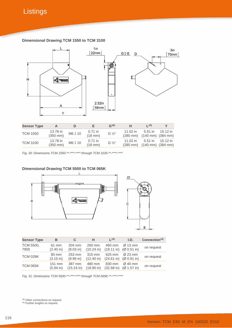
Version: TCM_E80_M_EN_160520_E010
116
Listings
Dimensional Drawing TCM 1550 to TCM 3100
Sensor Type A D E G18) H L19) Y
TCM 1550 13.78 in (350 mm) M6 10 0.71 in
(18 mm) G ½“ 11.02 in (280 mm)
5.51 in (140 mm)
15.12 in (384 mm)
TCM 3100 13.78 in (350 mm) M6 10 0.71 in
(18 mm) G ½“ 11.02 in (280 mm)
5.51 in (140 mm)
15.12 in (384 mm)
Fig. 30: Dimensions TCM 1550-**-****-**** through TCM 3100-**-****-****
Dimensional Drawing TCM 5500 to TCM 065K
Sensor Type B C H L19) I.D. Connection18) TCM 5500, 7900
61 mm (2.40 in)
204 mm (8.03 in)
260 mm (10.24 in)
460 mm (18.11 in)
Ø 13 mm (Ø 0.51 in) on request
TCM 028K 80 mm (3.15 in)
253 mm (9.96 in)
315 mm (12.40 in)
625 mm (24.61 in)
Ø 23 mm (Ø 0.91 in) on request
TCM 065K 151 mm (5.94 in)
387 mm (15.24 in)
480 mm (18.90 in)
830 mm (32.68 in)
Ø 40 mm (Ø 1.57 in) on request
Fig. 31: Dimensions TCM 5500-**-****-**** through TCM 065K-**-****-****
18) Other connections on request. 19) Further lengths on request.

Version: TCM_E80_M_EN_160520_E010
117
Listings
Dimensional Drawing TCM 230K
Fig. 32: Dimensions TCM 230K-**-****-****
Dimensional Drawing Meter-Mount Electronics TCE 8000/8100
Fig. 33: Dimensions compact electronics TCE 8000/8100
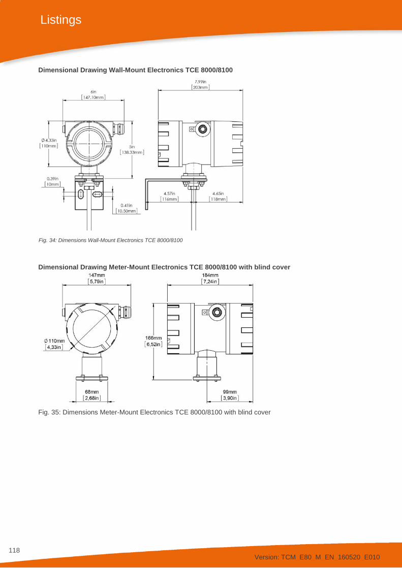
Version: TCM_E80_M_EN_160520_E010
118
Listings
Dimensional Drawing Wall-Mount Electronics TCE 8000/8100
Fig. 34: Dimensions Wall-Mount Electronics TCE 8000/8100
Dimensional Drawing Meter-Mount Electronics TCE 8000/8100 with blind cover
Fig. 35: Dimensions Meter-Mount Electronics TCE 8000/8100 with blind cover

Version: TCM_E80_M_EN_160520_E010
119
Listings
Dimensional Drawing Meter-Mount Electronics TCE 8000/8100 High Temperature
Fig. 36: Dimensions Meter-Mount Electronics TCE 8000/8100 High Temperature
Dimensional Drawing Connection head
Fig. 37: Dimensions Connection head

Version: TCM_E80_M_EN_160520_E010
120
Listings
Dimensional Drawing remote panel-mounted housings
Fig. 38: Dimensions TCE 8***-S-****
The required cutout for the panel is 92 mm +0.8/-0 mm x 92 mm +0.8/-0 mm.
The maximum thickness of the panel is 2 mm.
Fig. 39: Dimensions TCE 8***-L-****
The required cutout for the panel is 138 mm +1.0/-0 mm x 92 mm +0.8/-0 mm.
The maximum thickness of the panel is 2 mm.
7.4. WEEE and RoHS The TRICOR Coriolis Mass Flow Meter described herein is not subject to the WEEE directive and the corresponding national laws. At the end of life forward the TCM to a specialized recycling company and do not dispose it off as domestic waste.
The TCM described herein fully complies with the RoHS directive.

Version: TCM_E80_M_EN_160520_E010
121
Listings
7.5. List of Figures Fig. 1: Compact versions ......................................................................................................................................... 7 Fig. 2: Separate version with panel mount (left) or wall mount (right) electronics................................................... 7 Fig. 3: Rupture disc locations vary by the meter size and style .............................................................................. 9 Fig .4: Warning sticker found near the rupture disc on all meters ........................................................................... 9 Fig. 5: Principle of operation Coriolis Mass Flow Meter ........................................................................................ 18 Fig. 6: Operating Elements of TCE 8***-W and compact version ......................................................................... 20 Fig. 7: Operating Elements of TCE 8***-S ............................................................................................................. 21 Fig. 8: Operating Elements of TCE 8***-L-*-Ex ..................................................................................................... 21 Fig. 9: Operating Elements TCM ........................................................................................................................... 22 Fig. 10: Electrical terminals Junction box – Type A (Alu) ...................................................................................... 23 Fig. 11: Electrical terminals Junction box – Type H (1.4404/316L) ....................................................................... 23 Fig. 12: Electrical terminals TCE 8***-W and compact version ............................................................................. 24 Fig. 13: Electrical terminals TCE 8***-W-*-Ex ....................................................................................................... 26 Fig. 14: Electrical terminals TCE 8***-S ................................................................................................................ 28 Fig. 15: Electrical terminals TCE 8***-L-*-Ex ......................................................................................................... 30 Fig. 16: Recommended horizontal Installation ...................................................................................................... 36 Fig. 17: Vertical Installation ................................................................................................................................... 37 Fig. 18: Installation in a Drop Line ......................................................................................................................... 37 Fig. 19: Critical Installations ................................................................................................................................... 38 Fig. 20: Wiring diagram for power connections, DC operation .............................................................................. 42 Fig. 21: Wiring diagram for power connections, AC operation .............................................................................. 43 Fig. 22: Wiring diagram for digital I/O connections ................................................................................................ 44 Fig. 23: Wiring diagram for 4…20 mA current loop ............................................................................................... 45 Fig. 24: Wiring diagram for 4…20 mA current input .............................................................................................. 46 Fig. 25: Accuracy for Liquids ............................................................................................................................... 110 Fig. 26: Accuracy for Gases ................................................................................................................................ 112 Fig. 27: Dimensions TCM 0325-**-****-**** through TCM 0650-**-****-**** ........................................................ 114 Fig. 28: Meter Dimensions TCMH 0450, Ex/Ex1 ................................................................................................. 115 Fig. 29: Meter Dimensions TCMH 0450, Ex3 ...................................................................................................... 115 Fig. 30: Dimensions TCM 1550-**-****-**** through TCM 3100-**-****-**** ........................................................ 116 Fig. 31: Dimensions TCM 5500-**-****-**** through TCM 065K-**-****-**** ........................................................ 116 Fig. 32: Dimensions TCM 230K-**-****-**** ......................................................................................................... 117 Fig. 33: Dimensions compact electronics TCE 8000/8100.................................................................................. 117 Fig. 34: Dimensions Wall-Mount Electronics TCE 8000/8100 ............................................................................. 118 Fig. 35: Dimensions Meter-Mount Electronics TCE 8000/8100 with blind cover ................................................ 118 Fig. 36: Dimensions Meter-Mount Electronics TCE 8000/8100 High Temperature ............................................ 119 Fig. 37: Dimensions Connection head ................................................................................................................. 119 Fig. 38: Dimensions TCE 8***-S-**** ................................................................................................................... 120 Fig. 39: Dimensions TCE 8***-L-**** ................................................................................................................... 120
7.6. List of Tables Tab. 1: Connections TCM **** ............................................................................................................................... 40 Tab. 2: List of errors (ERR Codes) ........................................................................................................................ 54 Tab. 3: List of warnings (WARN Codes) ................................................................................................................ 55 Tab. 4: List of information (INFO Codes) ............................................................................................................... 55 Tab. 5: List of service parameters ......................................................................................................................... 57 Tab. 6: List of TCM device info .............................................................................................................................. 57

Version: TCM_E80_M_EN_160520_E010
122
Contact
8. Contact
TRICOR web page www.tricorflow.com
Sales North and South America: AW-Lake Company 2440 W. Corporate Preserve Dr. #600 Oak Creek WI 53154 USA
Tel.: +1 414 574 4300 [email protected] www.aw-lake.com
China: KEM Flow China Rm. 430, JInYuan Building, No. 36 BeiyuanLu, CN- Chaoyang District, Beijing 100012 P.R.CHINA Tel.:+86 10 84929567 / +86 10 84929577 Fax:+86 10 52003739 [email protected] www.kem-kueppers.cn
Southeast Asia: KEM Küppers Elektromechanik GmbH Representative Office (RO) Singapore 1003 Bukit Merah Central #06-32 Singapore 159836
UEN: T15RF0080G
Tel.: +65 6274 1130 [email protected] www.kem-kueppers.cn
Europe: KEM Küppers Elektromechanik GmbH Liebigstraße 5 DE-85757 Karlsfeld Germany
Tel.: +49 8131 59391-100 [email protected] www.kem-kueppers.com
Manufacturer KEM Küppers Elektromechanik GmbH Liebigstraße 5 DE-85757 Karlsfeld Germany
Tel.: +49 8131 59391-0 [email protected] www.kem-kueppers.com
AW-Lake Company 2440 W. Corporate Preserve Dr. #600 Oak Creek WI 53154 USA
Tel.: +1 414 574 4300 [email protected] www.aw-lake.com

Version: TCM_E80_M_EN_160520_E010
123
Original KEM/AWL document: TCM_E80_M_EN_160520_E010 Copyright KEM/AWL, Subject to change without notice