Triangulation of generative form for parametric design and rapid prototyping
8
Triangulation of generative form for parametric design and rapid prototyping Thomas Fischer a,b, * , Mark Burry a , John Frazer b a Spatial Information Architecture Laboratory, RMIT, Melbourne, Australia 1 b School of Design, The Hong Kong Polytechnic University, Hong Hum, Kowloon, Hong Kong, China 2 Abstract In this paper, we discuss recent developments in the ongoing implementation of a toolkit for developmental generative design and form-finding. We examine tissues of face-centered cubically close-packed voxel cells and topologically related structures for the possibility of 3D data conversion and of rapid prototyping applications. We also demonstrate how generative and parametric design can be integrated in order to enhance design flexibility and control, leading towards a potential extension of parametric design approaches. D 2004 Elsevier B.V. All rights reserved. Keywords: Parametric design; Digital morphogenesis; Cellular expression; Geometry triangulation 1. Introduction Being the result of a long-term software develop- ment project, the voxel automata system Zellkalku ¨l allows simulations of nonuniform, three-dimensional isospatial cellular automata structures with behavior based on decentralized, massively parallel, individu- ally high-level programmable cellular units. Its design being inspired by principles identified in develop- mental evolutionary biology, the system is used to explore tempo-spatial mechanisms of morphogenesis in developmental architectural and design contexts. It has also been applied in theoretical generative design research and in generative design teaching. For further discussions of the system, see Refs. [1–5]. Fig. 1 shows three modes of tissue representation currently supported by the system, all based on face- centered cubic close packing arrangement: rhombic dodecahedra, spheres and boctet trussesQ or bspace framesQ. The latter ones have been extensively discussed and applied by Fuller [6] who has also used the term bisotropic vector matrixQ for this type of structure. Close-packed spheres have previously been examined as models for coding data and programs as well as for representing composite form, for example by Lefever, Rastogi as well as by Kong [7] and Frazer as discussed in Ref. [8]. Rhombo-dodecahedral close- packing was identified as a common form of natural 0926-5805/$ - see front matter D 2004 Elsevier B.V. All rights reserved. doi:10.1016/j.autcon.2004.07.004 * Corresponding author. School of Design, The Hong Kong Polytechnic University, Hong Hum, Kowloon, Hong Kong, China. E-mail address: [email protected] (T. Fischer). 1 http://www.sd.polyu.edu.hk. 2 http://www.sial.rmit.edu.au. Automation in Construction 14 (2005) 233 – 240 www.elsevier.com/locate/autcon
-
Upload
thomas-fischer -
Category
Documents
-
view
215 -
download
2
Transcript of Triangulation of generative form for parametric design and rapid prototyping
www.elsevier.com/locate/autcon
Automation in Constructio
Triangulation of generative form for parametric design
and rapid prototyping
Thomas Fischera,b,*, Mark Burrya, John Frazerb
aSpatial Information Architecture Laboratory, RMIT, Melbourne, Australia1
bSchool of Design, The Hong Kong Polytechnic University, Hong Hum, Kowloon, Hong Kong, China2
Abstract
In this paper, we discuss recent developments in the ongoing implementation of a toolkit for developmental generative
design and form-finding. We examine tissues of face-centered cubically close-packed voxel cells and topologically related
structures for the possibility of 3D data conversion and of rapid prototyping applications. We also demonstrate how generative
and parametric design can be integrated in order to enhance design flexibility and control, leading towards a potential extension
of parametric design approaches.
D 2004 Elsevier B.V. All rights reserved.
Keywords: Parametric design; Digital morphogenesis; Cellular expression; Geometry triangulation
1. Introduction
Being the result of a long-term software develop-
ment project, the voxel automata system Zellkalkul
allows simulations of nonuniform, three-dimensional
isospatial cellular automata structures with behavior
based on decentralized, massively parallel, individu-
ally high-level programmable cellular units. Its design
being inspired by principles identified in develop-
mental evolutionary biology, the system is used to
explore tempo-spatial mechanisms of morphogenesis
0926-5805/$ - see front matter D 2004 Elsevier B.V. All rights reserved.
doi:10.1016/j.autcon.2004.07.004
* Corresponding author. School of Design, The Hong Kong
Polytechnic University, Hong Hum, Kowloon, Hong Kong, China.
E-mail address: [email protected] (T. Fischer).1 http://www.sd.polyu.edu.hk.2 http://www.sial.rmit.edu.au.
in developmental architectural and design contexts. It
has also been applied in theoretical generative design
research and in generative design teaching. For further
discussions of the system, see Refs. [1–5].
Fig. 1 shows three modes of tissue representation
currently supported by the system, all based on face-
centered cubic close packing arrangement: rhombic
dodecahedra, spheres and boctet trussesQ or bspaceframesQ. The latter ones have been extensively
discussed and applied by Fuller [6] who has also
used the term bisotropic vector matrixQ for this type ofstructure. Close-packed spheres have previously been
examined as models for coding data and programs as
well as for representing composite form, for example
by Lefever, Rastogi as well as by Kong [7] and Frazer
as discussed in Ref. [8]. Rhombo-dodecahedral close-
packing was identified as a common form of natural
n 14 (2005) 233–240

Fig. 1. Tissue representation based on rhombic dodecahedra, spheres and bisotropic vector matrixQ.
T. Fischer et al. / Automation in Construction 14 (2005) 233–240234
cell composition, for example by Kieser [9] and by
Thompson [10] and has been applied to physical form
composition for instance in the Digital Clay project at
Xerox Parc (www2.parc.com/spl/projects/modrobots/
lattice/digitalclay: May 2003). The idea of approach-
ing architectural form-finding and construction by
means of developmental cellular growth models has
been discussed in Refs. [8,11–14].
Despite its isospatial symmetry and—as Frazer [15]
has pointed out—excellent coding capabilities, from
the viewpoint of finding and modelling architectural
form, the basic spatial/cellular structure of face-
centered cubic close packing shows particular short-
comings with respect to its formal expressive capa-
bilities. The cellular voxel units generate structures
that are geometrically largely restrained to the autom-
ata system’s grid structure and the bjaggedQ cellular
geometries. The voxel shape especially dominates
those cellular designs that are based on lower voxel
resolutions and hence comprised of smaller numbers
of relatively large cells. The work described in this
paper aims at the development of system extensions to
overcome this limitation.
2. Voxel-based free-form modelling strategies
Today, artificial automatic form-finding scenarios
using developmental cellular approaches with adapt-
able cell geometries are very difficult to achieve
physically. In this area there are great challenges
ahead both in terms of the required self-organizational
capabilities as well as in terms of the mechanical and
structural engineering and robotics involved—see also
Fischer et al. [4]. Here, we examine how self-
organization could interrelate with three-dimensional
geometric operations in order to generate cellular
structures virtually, without confronting the physics of
dynamically geometry-adjusting compounds at this
point. Our objective is to utilize virtual space as a
generative simulation environment for dynamically
developing structures and at the same time to allow
for physical output by means of CAM facilities once a
form is considered interesting or useful during the
design process.
A variety of strategic approaches are possible to
support the generation of bfree formQ using associativegeometry based on developmental isospatial cell
composition. We have identified and previously
partially applied the following methods:
1. Using large numbers of automata at a high
resolution to approximate smooth 3D shapes.
One disadvantage of this approach is that smooth
surfaces are not achieved, only approximated at
the cost of exponentially increasing memory
consumption during shape generation. Formal
expression is moreover achieved primarily by
means of additive composition and not by para-
metric control of geometric relations. The useful-
ness of both parametric design principles in
combination has been discussed [16].
2. bSkinningQ of cell assemblies using surface fitting
algorithms.
T. Fischer et al. / Automation in Construction 14 (2005) 233–240 235
3. bSkinningQ using cell center points or cell
attributes to control separate skin geometry, e.g.,
mapping cell location or other cell-related data
onto free curve control-points.
4. Mapping of data generated in Zellkalkul’s autom-
ata structure onto secondary output geometries.
This and the above two strategies, however,
contradict the software’s intention to provide a
single unified geometric and data structure.
5. Parametric position control of cell polygon
vertices. This approach will be discussed in the
remaining part of this paper.
6. Parametric cell size control. This approach
involved distorting the lattice of cellular center
points and appears to be a highly interesting
future extension. We have, however, not yet
identified suitable operations and constraints for
the required geometric operations.
7. Changing the distances between cell center
points, i.e., substituting the isotropic vector
matrix by an banisotropic vector matrixQ. This
approach is a combination of the above two
approaches in which tissues are represented in
form of vector trusses instead of as bsolidQ cells.
Krawczyk [17] points out that in digital architec-
ture, form is often derived from initial sets of
parameters that can be changed to achieve alternative
results. He then proceeds to demonstrate how
adaptive geometry can be used to interpret the form
of cellular automata-based form in different ways. As
we have previously stated, parametric design aims to
limit the problems that come along with totally free
design situations—but it does so potentially at the
cost of the freedom of those situations; see Ref. [18],
p. 146. The extent to which parametric design
supports and restrains design situations largely
depends on the design system’s atomic resolution—
the granularity level dynamic parameters are applied
at and the system’s ability to bepigeneticallyQgenerate useful design solutions. In this sense, it
might be useful in many cases to break down single,
primary parametric patterns into smaller units based
on associative geometry as demonstrated by Krawc-
zyk, and to incorporate essential expressional infor-
mation into the developmental design code that
governs individual cellular behavior during form
generation. The overall design pattern will hence
not be described in form of a single geometric
topology but in form of a problem-specific devel-
opmental program while a generic parametric design
topology exists on the cellular level. The result of this
strategy is a parametrically enhanced generative
form-finding process that shares essential features
with growth processes in Nature. We speculate that
interrelating the (predominantly top-down-structured)
parametric design paradigm with the (predominantly
bottom-up-structured) generative design paradigm
yields very promising potentials for new parametric
generative design approaches. Previous discussions
of parametric design have concentrated on discussing
the approach as a rather top-down strategy that
requires some level of formal pre-rationalisation
before exploring forms [21]. If a cellular develop-
mental form-finding approach is applied as described
in this paper, true bottom-up parametric design
becomes possible.
3. Parametric logic, user interface and constraint
space definition
As a first step, the rhombic cell faces were
triangulated in order to allow vertices to move
individually without affecting other vertex positions
of the same face while continuing to allow tissues to
remain close-packed without void or overlapping
spaces. This triangulation is also useful in facilitating
the creation of triangle-based output file formats such
as STL, which is key in producing stereo-lithographic
rapid prototype models of generated form. For these
two purposes, we have split all the rhombic faces of
the dodecahedral units into two isosceles triangles as
illustrated by the dashed lines in the middle of Fig. 2.
As a next step, it was necessary to identify the
movement ranges of all vertices in order to achieve
useful geometric constraints for parametric manipu-
lation. By bmovement rangesQ we refer to the spaces
or domains within which each vertex is allowed to
move while avoiding vertex eversions (which would
describe unwanted inverse spaces). This eversion
problem would for instance occur if vertices {1}
and {9} in the middle of Fig. 2 were to change their
positions in such a way that {9} will be located above
{1}; the cellular space between both vertices would
evert and result in an undefined space.

Fig. 2. Rhombo-dodecaherdal voxel geometry, triangulation and vertex ranges, STL format illustration.
T. Fischer et al. / Automation in Construction 14 (2005) 233–240236
To allow vertices to move freely without mutual
eversion, the movement ranges must fill the entire
tissue space without overlapping and hence allow
close packing themselves. The left illustration shown
in Fig. 2 shows a rhombic dodecahedron with faces
numbered using Miller indices (mineralogical face
identification system), vertex numbers as used in
Zellkalkul and two different vertex types labeled daTand dbT. Vertices between six adjacent cells (labeled
daT) have octahedral ranges while vertices between
four adjacent cells (labeled dbT) have tetrahedral
ranges as shown in the two left illustrations in Fig.
3. The side length (or in Fuller’s terminology: the
geodesic vector length) of both geometries is 1
(identical to cell diameter). The second right of Fig.
3 shows both types of these platonic shapes (second
from left, octahedra are only shown half) and (outer
right) their ability to close-pack into cuboctahedral
assemblies. The 12 cells neighboring the central cell
are shown as wire frames in both illustrations. By
constraining vertices to always remain within their
Fig. 3. Tetrahedral and octahedral vector matrices and result
ranges, this topology prevents self-intersecting cell
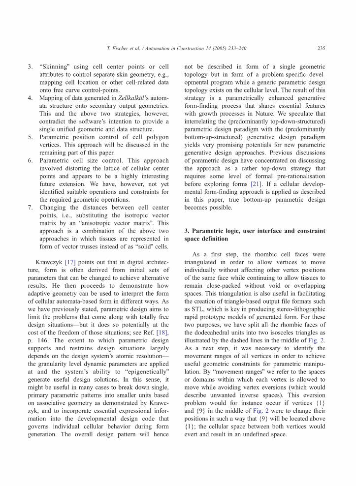
surfaces. Fig. 4 shows sections through the assembly
of overlapping cuboctahedral vertex movement ranges
of 12 close-packed rhombo-dodecahedral cells in two
orientations.
The last step of our strategy for approximating free
form required a suitable user interface and control
mechanism, which allows users to move vertices in
intuitive ways using scripting functions. In order to
keep the user interface for vertex position control
simple, intuitive and yet as flexible as possible, we
have designed it not to distinguish between the two
different vertex types daT and dbT despite the fact that
they are internally processed in different ways. We
have decided to use a pressure model that allows users
to control the pressure cells exert in the direction of a
given vertex. The two left illustrations on Fig. 3 show
the force vectors with which adjacent cells can
manipulate both types of vertices. An advantage of
using a pressure model for vertex position control is
that positions, as in Nature, result relatively from
ing cuboctahedral cluster of vertex movement ranges.
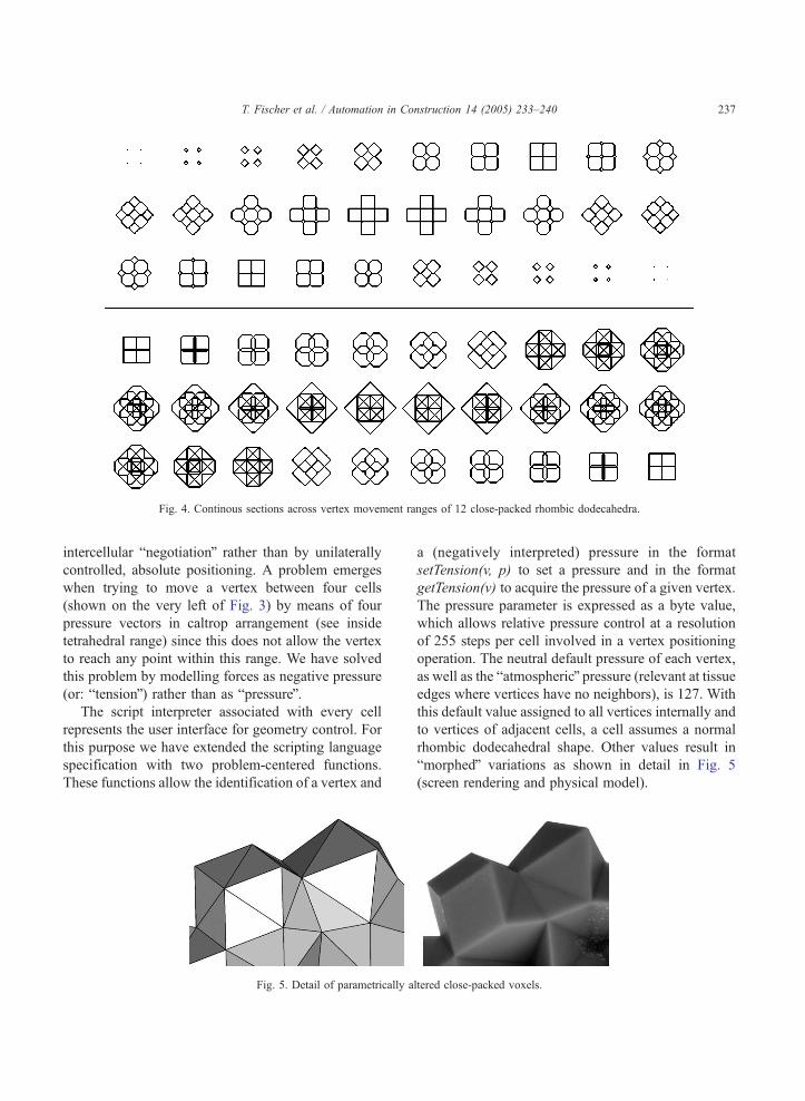
Fig. 4. Continous sections across vertex movement ranges of 12 close-packed rhombic dodecahedra.
T. Fischer et al. / Automation in Construction 14 (2005) 233–240 237
intercellular bnegotiationQ rather than by unilaterally
controlled, absolute positioning. A problem emerges
when trying to move a vertex between four cells
(shown on the very left of Fig. 3) by means of four
pressure vectors in caltrop arrangement (see inside
tetrahedral range) since this does not allow the vertex
to reach any point within this range. We have solved
this problem by modelling forces as negative pressure
(or: btensionQ) rather than as bpressureQ.The script interpreter associated with every cell
represents the user interface for geometry control. For
this purpose we have extended the scripting language
specification with two problem-centered functions.
These functions allow the identification of a vertex and
Fig. 5. Detail of parametrically a
a (negatively interpreted) pressure in the format
setTension(v, p) to set a pressure and in the format
getTension(v) to acquire the pressure of a given vertex.
The pressure parameter is expressed as a byte value,
which allows relative pressure control at a resolution
of 255 steps per cell involved in a vertex positioning
operation. The neutral default pressure of each vertex,
as well as the batmosphericQ pressure (relevant at tissueedges where vertices have no neighbors), is 127. With
this default value assigned to all vertices internally and
to vertices of adjacent cells, a cell assumes a normal
rhombic dodecahedral shape. Other values result in
bmorphedQ variations as shown in detail in Fig. 5
(screen rendering and physical model).
ltered close-packed voxels.

T. Fischer et al. / Automation in Construction 14 (2005) 233–240238
4. STL data output
As discussed above, the rhombic faces of the
dodecahedral units had to be broken down into two
triangles each to allow for individual vertex move-
ment. With the coordinates of these triangles avail-
able, it was easily possible to develop an STL file
output interface. While there are solutions publicly
available that allow STL data to be loaded into
Java3D scene graphs (see http://www.j3d.org/utilities/
loaders.html), we believe the work discussed here to
be one of the very first STL output solutions for
Java3D-based modelling. Of the two STL specifica-
tions existing, one is based on ASCII data while the
other one is based on much more space-efficient
binary data. We have found both formats to have
specific advantages and disadvantages in our context.
The ASCII variant has proved to be more human-
readable and hence bdeveloper friendlyQ during
software development and debugging, while the
binary format produces significantly smaller files
and allows for more efficient and faster software
analysis. We have therefore implemented output
Fig. 6. Enclosure structure based on a design by Frazer (1966–68) based
geometries (right).
facilities for both formats. More details on the ASCII
and binary STL specifications can be found in Ref.
[19], pp. 227 ff. The STL specifications require
triangular face orientation (normal orientation) to be
expressed redundantly by counter-clockwise vertex
order as well by an outward-directed perpendicular
normal vector as illustrated on the right of Fig. 2. Our
STL filter hence only needs to find the vertex order
appropriate for each triangle’s normal orientation and
a fourth point in space denoting the normal vector.
Internally, Java3D represents complex models as
triangle-strips, which can be analyzed and allow any
shape to be converted to STL. We have already made
significant progress into this direction. The more
complex data generated by our system, however,
describe close-packed spheres and space frame trusses
which contain many half-enclosed spaces that easily
involve support material complications in rapid
prototyping. Since the availability of multicolor rapid
prototyping machines, the STL specification has been
enhanced to accommodate color data. Not having this
type of equipment immediately available, we have not
yet focused on this option. With respect to inter-
on dodecahedral units in original (left) and parametrically altered

T. Fischer et al. / Automation in Construction 14 (2005) 233–240 239
operability with other 3D modelling and rendering
packages, STL output of space frame structures and
spheres has already proven to be very useful, and
color-enhanced data output appears to be a highly
interesting possibility for future work.
Fig. 6 shows renderings and close-up photographs
of rapid prototype models based on a 1968 enclosure
design for the Coventry Preparatory School by Frazer
[20] and Frazer and Connor [13]. Both models are
generated in massively parallel developmental pro-
cesses in which an initial 3D data array is expressed
by virtual cellular proliferation. Once the final shape
has developed, close-range intercellular communica-
tion is used to generate a local sense of cellular
identity. This sense of identity is then used to trigger
geometric alterations in parts of the design. The model
on the left is based on unaltered rhombo-dodecahedral
voxel units and shows a jagged model surface. The
model on the right shows one surface approximating a
smooth surface and one dspikyT surface achieved by
decentralized parametric cell geometry control.
5. Conclusion
We have given insights into our toolmaking work
in the area of computer-aided developmental evolu-
tionary design. The system we have described allows
for parametrically enhanced generative form-finding
and modelling processes that can either remain within
or transcend paradigms of natural growth and devel-
opment. It utilizes virtual space as an experimental
form-finding environment but supports STL file
export for interoperability with common 3D model-
ling packages as well as CAM output facilities such as
STL rapid prototyping machines. As the early experi-
ments we have shown suggest, one strategy of
overcoming previously discussed shortcomings of
parametric design could be the introduction of fine-
grain associative geometry to voxel-based generative
design in analogy to growth and developmental
expression of cellular form in Nature.
Acknowledgements
The authors gratefully acknowledge the support
from their colleagues at the Spatial Information
Architecture Laboratory at the Royal Melbourne
Institute of Technology and at the School of Design
at The Hong Kong Polytechnic University. We also
thank Torben Fischer from the Faculty of Mathematics
at the University of Gfttingen for his excellent
contribution in algorithm and filter development as
well in implementing the discussed software. Many
thanks also to the workshop team of the School of
Design and The Industrial Centre of The Hong Kong
polytechnic University for their excellent rapid proto-
typing support.
References
[1] T. Fischer, T. Fischer, C. Ceccato, Distributed agents for
morphologic and behavioral expression in cellular design
systems, in: G. Proctor (Ed.), Thresholds. Proceedings of
the 2002 Annual Conference of the Association for
Computer Aided Architectural Design, Department of
Architecture, College of Environmental Design, California
State Polytechnic University, Pomona, Los Angeles, 2002,
pp. 111–121.
[2] T. Fischer, Computation-universal voxel automata as material
for generative design education, in: Celestino Soddu, et al.,
(Eds.), Proceedings of the 5th Conference and Exhibition on
Generative Art 2002, Generative Design Lab DiAP, Politech-
nico di Milano University, Italy, 2002, pp. 10.1–10.11.
[3] T. Fischer, T. Fischer, Parametric voxel geometry control for
digital morphogenesis, Proceedings of the 19th European
Workshop on Computational Geometry, Institute for Computer
Science I, University of Bonn, Germany, 2003, pp. 35–40.
[4] T. Fischer, M. Burry, J. Frazer, How to plant a subway system,
in: Mao-Lin Chiu, et al. (Eds.), Digital Design, Research and
Practice, The Proceedings of The 10th International Confer-
ence of Computer Aided Architectural Design Futures,
National Cheng Kung University, Tainan, Taiwan, 2003,
Publication pending.
[5] T. Fischer, T. Fischer, Toolmaking for digital morphogenesis,
in: G. Proctor, W. Jabi (Eds.), International Journal of Design
Computing, vol. 6, 2003.
[6] R.B. Fuller, Synergetics. Explorations in the Geometry of
Thinking, Macmillan, New York, 1975.
[7] G. Kong, 1994. Cellular Automatas and bStacking BallsQ.Technical dissertation forming part of the Diploma of the
Architectural Association, London.
[8] J. Frazer, An Evolutionary Architecture, Architectural Asso-
ciation, London, 1995.
[9] D.G. Kieser, Phytotomie, oder Grundzqge der Anatomie der
Pflanzen, Crfcker, Jena, 1815.[10] D.W. Thompson, On Growth and Form. The Complete
Revised Edition, Dover Publ, New York, 1992.
[11] K. Zuse, Der Computer. Mein Lebenswerk, Springer Verlag,
Berlin, 1993.

T. Fischer et al. / Automation in Construction 14 (2005) 233–240240
[12] F. Otto, IL3 Biologie und Bauen, Mitteilungen des Instituts fqrLeichte Fl7chentragwerke, Stuttgart, 1971.
[13] J. Frazer, J. Connor, A conceptual seeding technique for
architectural design, PArC 79 Proceedings, AMK, Berlin,
Online Conferences, Uxbridge, UK, 1979.
[14] A.R. Smith, Simple non-trivial self-reproducing machines, in:
C.G. Langton, et al. (Eds.), Artificial Life II, vol. X of SFI
Studies in the Sciences of Complexity, Addison-Wesley,
Redwood City, CA, 1992, pp. 709–725.
[15] J. Frazer, Datastructures for rule-based and genetic design, in:
T.L. Kunii (Ed.), Visual Computing-Integrating Computer
Graphics with Computer Vision, Springer-Verlag, Tokyo,
1992, pp. 731–744.
[16] B. Kolarevic, Digital morphogenesis and computational
architectures, in: J.R. Kos (Ed.), The Proceedings of
SIGraDi2000-Construindo (n)o espacio digital (constructing
the digital Space), Facultad de Arquitectura, Universidad
Nacional de Mar del Plata, Rio de Janeiro, Brazil, 2000,
pp. 98–103.
[17] R.J. Krawczyk, Experiments in form generation using
cellular automata, in: K. Koszewski, S. Wrona (Eds.),
Design e-Ducation. Connecting The Real and the Virtual.
Proceedings of the 20th eCAADe Conference, Warsaw
University of Technology, Warsaw, Poland, 2002, pp.
552–555.
[18] T. Fischer, M. Burry, R. Woodbury, Object-oriented mo-
delling using XML in computer-aided architectural and
educational CAD, in: Beng-Kiang Tan, et al. (Eds.), CAA-
DRIA2000. Proceedings of the 5th Conference on Computer
Aided Architectural Design Research in Asia, Singapore, 2000,
pp. 145–155.
[19] M. Burns, Automated Fabrication. Improving Productivity in
Manufacturing, Prentice Hall, Englewood Cliffs, 1993.
[20] J. Frazer, Reptiles, Architectural Design 4/1974, 1974,
pp. 231–240.
[21] M. Burry, M. Zolna, Architectural design based on parametric
variation and associative geometry, in: B. Martens, et al.
(Eds.), Challenges of the Future, Proceedings of the 15th
eCAADe Conference, Osterreich Kunst und Kulturverlag,
Vienna, Austria1997, pp. 1–11.