Structural Repair and Maintenance of Historical Buildings 35

TECHNICAL RECOMMENDATIONS FOR HIGHWAYS
Draft TRH 20 THE STRUCTURAL DESIGN, CONSTRUCTION AND MAINTENANCE OF UNPAVED ROADS 1990 ISBN 0 908381 87 5 Pretoria, South Africa, 1990

Published by Department of Transport P O Box 415 PRETORIA 0001 Republic of South Africa for the Committee of State Road Authorities PRINTED FEBRUARY 1990 Printed in the Republic of South Africa by V & R Printing Works (Pty) Ltd. PRETORIA

PREFACE TECHNICAL RECOMMENDATIONS FOR HIGHWAYS (TRH) are written for the practising engineer and describe current, recommended practice in selected aspects of highway engineering. They are based on South African experience and on the results of research and have the full support of the Committee of State Roads Authorities (CSRA). This document has been written by Dr P Paige-Green of the Division of Roads and Transport Technology under the guidance of a subcommittee of the Highway Materials Committee consisting of: Prof A T Visser – University of Pretoria, Pretoria (Chairman) Mr N van der Walt – DOT, Pretoria Mr G D van Zyl – TPA, Pretoria Mr A Thompson – NPA, Pietermaritzburg Mr E de Villiers – CPA, Cape Town Mr J du Pisani – OFSPA, Bloemfontein Mr S Poolman – SWA DOT, Windhoek Mr T van Niekerk – DBSA, Halfway House Mr P A Pienaar – Jordaan and Joubert, Pietersburg. To confirm its validity in practice, it will be circulated in draft form for a trial period before being submitted to the CSRA for approval. During this period you are welcome to send suggestions for improvement to the Chief Materials Engineer: Department of Transport, P O Box 415, Pretoria, 0001 or The Director, DRTT-CSIR, P O Box 395, Pretoria 0001. Eventually a revised document, approved by the CSRA, will be issued as a full TRH in both languages. SOME NEW DEFINITIONS Grading coefficient (Gc) = ((per cent passing 26,5 mm – per cent passing 2,0 mm) x per cent passing 4,74 mm)/100 Oversize index (Io) = per cent retained on 37,5 mm sieve Plastic factor (PF) = product of plastic limit and per cent passing 0,075 mm sieve (PL x P0,075) Shrinkage product (Sp) = Bar linear shrinkage from liquid limit x per cent passing 0,425 mm sieve
CONTENTS 1 INTRODUCTION ..............................................................................................................................6
1.1 Background ...............................................................................................................................6 1.2 Definitions..................................................................................................................................6 1.3 Traffic ........................................................................................................................................6 1.4 Basic economic principles ...........................................................................................................7
2 TYPICAL UNPAVED ROAD DEFECTS ..............................................................................................7 2.1 Dustiness ..................................................................................................................................7 2.2 Potholes ....................................................................................................................................8 2.3 Stoniness ..................................................................................................................................9 2.4 Corrugations ..............................................................................................................................9 2.5 Ruts ........................................................................................................................................12 2.6 Cracks.....................................................................................................................................12 2.7 Ravelling .................................................................................................................................12 2.8 Erosion ....................................................................................................................................13 2.9 Shape .....................................................................................................................................13 2.10 Slipperiness .........................................................................................................................13 2.11 Impassibility (trafficability)......................................................................................................14 2.12 Gravel loss ...........................................................................................................................14 2.13 Excessive loose material .......................................................................................................14
3 DESIGN OF UNPAVED ROADS .....................................................................................................14 3.1 Geometric design.....................................................................................................................14 3.2 Thickness design .....................................................................................................................15
3.2.1 Minimum thickness required for subgrade protection (t)........................................................15 3.2.2 Traffic induced compaction (Ct) ..........................................................................................16 3.2.3 Predicted annual gravel loss (GLp x Ld) ...............................................................................16
3.3 Material selection .....................................................................................................................17 3.3.1 Rural Roads ......................................................................................................................17 3.3.2 Urban Roads .....................................................................................................................18 3.3.3 Haul Roads .......................................................................................................................19
4 CONSTRUCTION ...........................................................................................................................19 4.1 Subgrade preparation ...............................................................................................................19 4.2 Gravel operations .....................................................................................................................20 4.3 Wearing course construction .....................................................................................................21
4.3.1 Thickness .........................................................................................................................21 4.3.2 Compaction.......................................................................................................................21 4.3.3 Finish and shape...............................................................................................................22
4.4 Drainage..................................................................................................................................22 4.4.1 Surface water ....................................................................................................................22 4.4.2 Subsurface water ..............................................................................................................23
5 MAINTENANCE .............................................................................................................................24 5.1 Maintenance management ........................................................................................................24 5.2 Levels of serviceability..............................................................................................................25 5.3 Practical aspects of maintenance ..............................................................................................25
5.3.1 Roadside maintenance ......................................................................................................25 5.3.2 Drainage maintenance .......................................................................................................26 5.3.3 Surface maintenance.........................................................................................................27
5.4 Safety aspects .........................................................................................................................29 5.5 Cost effectiveness of maintenance ............................................................................................29
6 REHABILITATION AND UPGRADING .............................................................................................30 7 ECONOMIC ASPECTS ...................................................................................................................31
7.1 General ...................................................................................................................................31 7.2 Upgrading................................................................................................................................32
REFERENCES......................................................................................................................................32 APPENDIX A : Recommended test method for the grading analysis of unpaved road wearing course materials 34 1 SCOPE ..........................................................................................................................................34 2 APPARATUS .................................................................................................................................35 2.1 A suitable riffler. ..........................................................................................................................35 2.2 A 37,5 mm sieve, recommended diameter 450 mm........................................................................35

2.3 The following sieves, 200 mm in diameter, complying with the requirements of SABS 197 (sieves larger than 4,75 mm must be of perforated plate and sieves 4,76 mm and smaller of woven wire mesh): 26,5 mm, 19,0 mm, 13,2 mm, 6,7 mm, 4,75 mm, 2,0 mm, 0,425 mm and 0,075 mm together with a bottom pan and lid. ..................................................................................................................................................35 2.4 A mechanical sieve shaker (optional). ...........................................................................................35 2.5 A balance with a pan to weigh up to 25 kg, accurate to 5 g. ............................................................35 2.6 A balance with a pan to weigh up to 5 kg, accurate to 1 g. ..............................................................35 2.7 A suitable basin about 450 mm in diameter. ..................................................................................35 2.8 A pan about 300 mm square. .......................................................................................................35 2.9 Flat pans about 200 mm in diameter and 30 cm deep. ...................................................................35 2.10 A drying oven, thermostatically controlled and capable of maintaining a temperature of 105 to 110ºC. 35 2.11 The following brushes for cleaning the sieves: a brass or wire brush measuring approximately 50 mm x 25 mm with bristles not more than 25 mm long, and hard-bristle brushes measuring approximately 50 mm x 25 mm. ........................................................................................................................................35 2.12 A 150 mm nominal diameter iron mortar and pestle and a rubber-tipped pestle. ...........................35 3 METHOD .......................................................................................................................................35 3.1 Size of bulk sample .....................................................................................................................35 3.2 Drying.........................................................................................................................................35 3.3 Oversize material ........................................................................................................................35 3.4 Quartering...................................................................................................................................36 3.5 Washing .....................................................................................................................................36 3.6 Sieving .......................................................................................................................................36 4 CALCULATIONS ............................................................................................................................36 4.1 Calculate the mass of the -0,075 mm material by subtracting the total mass of the material retained on the sieves from the mass of the original test sample (see 3.3). .................................................................36 4.2 Convert the mass of each fraction retained between two sieves to a percentage of the total dry mass of the test sample (see 3.3 i.e. only the fraction smaller than 37,5 mm). ....................................................36 4.3 Convert the percentages retained on the sieves to percentages passing the sieves. ........................36 4.4 Calculate the percentages to the nearest 0,1. ................................................................................36 4.5 Calculate the “Oversize index” as the mass of sample retained on the 37,5 mm sieve as a percentage of the total mass of the original dried bulk sample. ...................................................................................36 5 NOTES ..........................................................................................................................................37 5.1 The washing procedure for samples containing a high percentage of -0,075 mm material may be facilitated by dry sieving the sample prior to washing. ..............................................................................37 5.2 Table 2 gives the maximum allowable mass of material retained on a specific sieve 200 mm in diameter. To prevent overloading of a sieve, the material should be divided and sieved in more than one operation...............................................................................................................................................37 APPENDIX B : BASIC listing of model to predict annual gravel loss and regravelling frequency .........38 APPENDIX C : BASIC listing of model to predict change in roughness with time and blading frequency39 APPENDIX D : Check-list of maintenance management input requirements ..........................................40 LIST OF FIGURES FIGURE 1 The “forced oscillation theory” for the formation of corrugation. (After Heath and Robinson, 1980).
......................................................................................................................................................10 FIGURE 2 Examples of loose and fixed corrugations ...............................................................................11 FIGURE 3 Relationship between shrinkage product, grading coefficient and performance of unpaved wearing
course gravels ................................................................................................................................18 FIGURE 4 Ditches and drains ................................................................................................................23 FIGURE 5 Relationship between average road roughness and total vehicle operating costs.......................31 LIST OF TABLES TABLE 1 Recommended material specifications for unpaved rural roads ..................................................17 TABLE 2 Recommended material specifications for unpaved roads in urban areas ....................................19 TABLE 3 Recommended material specifications for unpaved haul roads ...................................................19 TABLE 4 Definition of levels of serviceability ...........................................................................................25 Appendix A Table 1: Approximate mass of bulk and test samples .............................................................35 Appendix A Table 2: Maximum allowable mass on sieves ........................................................................37
1 INTRODUCTION
1.1 Background The economic well-being of a country is closely related to the state of its road network. The agricultural, mining, forestry and tourist industries of all countries rely heavily on an adequate network of all-weather roads for their economic viability. The future development of most third-world countries is fundamentally dependent on the existence of adequate road networks.
Unpaved roads are the major component of the road network in most developing countries and comprise a significant portion of the network even in highly developed countries such as the United States. It is unlikely that the overall percentage of unpaved roads will decrease significantly in the foreseeable future and techniques for improving the unpaved road networks are thus becoming increasingly important. Many unpaved roads are presently designed with very little scientific input and are constructed from the nearest available material. Minimal attention is directed towards providing an adequate formation or effective drainage, or towards selecting suitable material for the prevailing conditions. Minimal maintenance is the norm in most developing areas. It is generally acknowledged, however, that worthwhile benefits can be obtained from an appropriate level of engineering input (Ferry, 1986).
This TRH provides guidelines for the structural design, construction and maintenance of unpaved roads. It identifies design and construction techniques which will result in roads of a higher standard without the need for additional funds, makes recommendations for improving the management of unpaved road maintenance and discusses a number of appropriate maintenance techniques. Aspects such as the planning of unpaved road networks and the geometric design are considered to be beyond the scope of this manual and are not discussed in any detail. These are covered in greater detail in DRTT (1989).
1.2 Definitions Unpaved roads may be divided into earth tracks, earth roads or gravel roads.
Earth tracks are the simplest “low volume roads” and generally consist of parallel ruts separated by vegetation, delineating a rural access route. These tracks are not engineered and are often impassable during or after wet weather conditions. In most cases they carry less than about five vehicles per day. They are usually used as local access roads by private land owners and small communities and are not normally constructed or maintained by a recognised road authority. Some earth tracks through Kalahari sand in South West Africa/Namibia are, however, maintained by the road authorities.
Earth roads are classified as those on which no imported gravel is used, but the in situ material is cleared of vegetation and lightly compacted (usually by traffic only). The roads are often shaped to some extent with the material which is removed from the side of the road to form side-drains. This is used to form a small embankment and raise the road slightly. These roads are usually constructed by a road authority or regional development institution and are important for the economic or social advancement of the area. Unlike earth tracks, periodic maintenance should be applied to earth roads.
Gravel roads have a designed layer of imported material which is typically constructed to a specified standard and width and provides an all-weather surface. The vertical and horizontal alignment is generally upgraded to appropriate standards. Maintenance of gravel roads is carried out on a more regular and systematic basis and a higher level of service is obtained, although the roughness varies considerably with time and depends significantly on the maintenance activity. This manual is primarily intended for use with gravel roads but many of the guidelines and recommendations are equally applicable to earth roads. Some roads may in fact be a combination of earth and gravel, where gravel is only imported for certain sections, for which the in situ material is unsuitable.
1.3 Traffic Unpaved roads are nearly always lightly trafficked. Should the traffic exceed about 300 vehicles per day, it is often economically viable to surface them with a bituminous seal (Richards, 1978), although in developing areas a figure of 400 vehicles per day is probably more appropriate. Visser (1984) provided an algorithm based on the overall economic criteria to evaluate the optimal timing of upgrading for traffic up to 400 vehicles per day. This manual considers mainly those roads carrying less than 200 vehicles per day, with
less than 60 of these being heavy (80 kN axles), although much of the discussion is applicable to roads carrying 400 vehicles per day or more.
1.4 Basic economic principles The fundamental theory of economic analysis applied to unpaved road construction is the comparison of the benefits and costs of providing alternative facilities. The benefits are the expression in economic terms of the advantages of the particular action, e.g. fuel and time savings with reduced roughness; a reduction in dust and maintenance on paved roads compared to unpaved roads; reduced accidents; etc. The cost of a project is a combined function of the initial construction cost, the routine and periodic maintenance costs, road user costs and the salvage value of the facility. The benefits and costs for each alternative are analysed in terms of the “economic cost” (i.e. excluding taxes, subsidies and duties) and discounted over the expected design lives of the facilities. Discounting is necessary to allow the direct comparison of costs and benefits between the first and subsequent years. A number of techniques are available for the economic evaluation of alternative options, the most common ones being the “present worth of costs”, the “benefit/cost ratio” or the “internal rate of return”. Other techniques such as the “equivalent uniform annual cost”, “equivalent uniform annual net return” and the “net present value” are available (Schutte, 1984) and the one most appropriate for the purpose should be selected. Many problems occur in the economic analysis of unpaved roads in comparison with paved roads. Unpaved roads require continual maintenance and their condition can be significantly affected by periods of excessive traffic volumes or inclement weather. The accurate estimation of maintenance costs is therefore difficult. Other aspects such as expressing the effects of dust in residential areas, or improved passenger comfort on the lengthy commuter routes common in southern Africa complicate the analyses. Other aspects such as the effects of the economic stimulation of an area through improved roads and improved access to a developing area are difficult to take into account in economic analyses. Guidelines for the determination of the economic merit of projects involving the upgrading of rural roads in the developing areas of southern Africa are described by Schutte et al, 1988, and are not covered in this report.
2 TYPICAL UNPAVED ROAD DEFECTS Typical defects which may affect unpaved roads are dustiness, potholes, stoniness, corrugations, ruts, cracks, ravelling (formation of loose material), erosion, slipperiness, impassability and loss of surfacing or wearing course. Many of these have a direct effect on the road roughness and safety. The causes of each of these modes of distress and possible remedial actions are discussed in turn.
2.1 Dustiness Dust is the fine material released from the road surface under the wheels of moving vehicles and the turbulence caused by vehicles. Silt-sized particles (2 – 75 µm) are the predominant elements in dust and the quantity of dust generated by a vehicle is a function of its aerodynamic shape, speed of travel and the surfacing material properties. Dust is undesirable from a number of points of view: Safety – Dust affects visibility significantly and can result in highly unsafe following and passing conditions (especially during peak traffic periods). Comfort – Excessive dust can result in significant discomfort to drivers and passengers, especially in the hotter areas of southern Africa where it is impractical to keep all windows closed. Health – Although no positive evidence of the detrimental effects of dust on the health of road users has been produced locally, the problem has been investigated in the United States. Certain materials such as asbestos and silica dust, which may occur in some wearing course gravels, can certainly be considered undesirable from a health aspect. Vehicle damage – Dust can significantly increase the rate of wear of moving parts of vehicles, under both dry and wet conditions, when it acts as a grinding paste. Vegetation – The effects of dust on roadside vegetation and crops is difficult to estimate, but may be significant in certain areas, especially where intensive agriculture or stock and game farms are found.

Environmental – Excessive dust generation often results in air pollution, this being particularly prevalent in deep valleys during winter. Temperature inversions result in thick blankets of dust being suspended in the air. Economic – The loss of wearing course material in the form of dust results in a change in the properties of the wearing course gravel. Materials which initially had adequate plasticity have been observed to form corrugations as the fines are lost. This should be borne in mind during regular grader maintenance. Dust is generally considered by the travelling public to be unacceptable when it totally obscures vehicles behind a moving vehicle, either following vehicles or those passing from the opposite direction, especially near road junctions. The potential dustiness of a material is very difficult to predict. Although material composition is the major characteristic affecting dustiness, aspects such as the vehicle volume, mix and speeds of vehicles, moisture content of the road, looseness of the material, maintenance frequency and wind all affect the apparent dustiness. Nearly all materials are dusty and research has shown that the probability of the dust being acceptable is highest when the Shrinkage Product (Sp; product of bar linear shrinkage and percentage passing 0,425 mm sieve) is restricted to values between 100 and 240 (Paige-Green, 1989a). In many cases it may be necessary to apply dust palliatives in order to bind the dust particles. A number of dust palliatives are commercially available but each one has to be tested individually in order to identify its suitability and cost-effectiveness for the material under consideration. Common dust palliatives may be bitumen- or tar-based, inorganic compounds (magnesium and calcium chlorides being the most popular), ligno-sulphonate (a product of the sulphate timber pulping process) and various commercial products of variable effectiveness. These are fully summarised by Paige-Green (1989c) and research into dust palliatives for local conditions is in progress.
2.2 Potholes Potholes play a significant role in the development of roughness on unpaved roads and may cause substantial damage to vehicles if they are allowed to develop and increase in size. The effect of potholes on vehicles depends both on the depth and diameter of the pothole. The potholes which affect vehicles most are those between 250 mm and 1 500 mm in diameter with a depth of more than 50 to 75 mm. Potholes may arise from the following processes:
poor road shape and drainage; poor grader operation practice, e.g. plucking of oversize material and destruction of the crown; compaction of material behind oversize stones under wheel loads; enlargement of corrugation troughs; deformation of weak subgrades and wearing courses; subsidence of animal and insect burrows; disintegration of highly cracked roads (i.e. excessive plasticity); disintegration of soft oversize material; dispersive soils; poor compaction; material and moisture variability.
Once pothole formation has been initiated (irrespective of the cause), the drainage deteriorates, water ponds in the depressions and the potholes are enlarged by traffic. Particular attention should be given to maintaining adequate cross-fall on such sections. The enlargement occurs through compaction and remoulding of the weakened material (in the wet state) and removal of the material from the hole by wheels and splashing. Materials with a low soaked strength are thus likely to develop larger and deeper potholes in shorter periods. The influence of drainage on pothole formation is clearly manifested by the general absence of potholes on grades. Potholes are usually worst at the bottom of sag vertical curves in the alignment, on level road sections with poor shape, and near bridges. Potholes are difficult to repair, very few being successfully repaired by routine grader maintenance or by manual filling behind the grader. The only successful way to repair them is by enlarging the hole, overfilling it

with moist gravel and compacting it (in layers, if necessary). Many potholes have been recorded in the same place for over two years, gradually becoming wider and deeper despite routine grader maintenance. It may be necessary in certain areas where a particularly pothole-susceptible material is common to have a team specifically for patching potholes.
2.3 Stoniness Stoniness is the relative percentage of material in the road which is larger than a recommended maximum size (usually 37,5 mm). This is one of the few defects of unpaved roads which can usually be controlled. Excessively stony roads result in the following problems:
unnecessarily rough roads; difficulty with grader maintenance; poor compaction of areas adjacent to stones (leading to potholes and ravelling); the development of corrugations; thick loose material is necessary to cover the stones.
Many geological materials, particularly shale and hornfels, produce flaky or sharp stones under crushing or grid rolling. These can cause extensive damage to tyres and affect the safety of the roads significantly. Consequently, use of materials exhibiting these characteristics should be avoided where possible. Some mudrocks may, on exposure to the atmosphere, deteriorate rapidly from a hard material to a soft, fine-grained “soil”, causing significant problems. Control of the factors which lead to stony roads is discussed fully in Section 4.2.
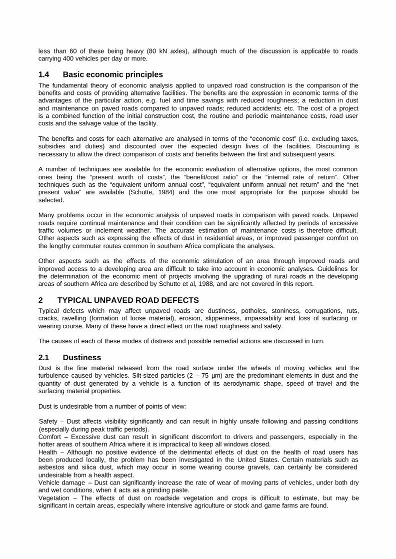
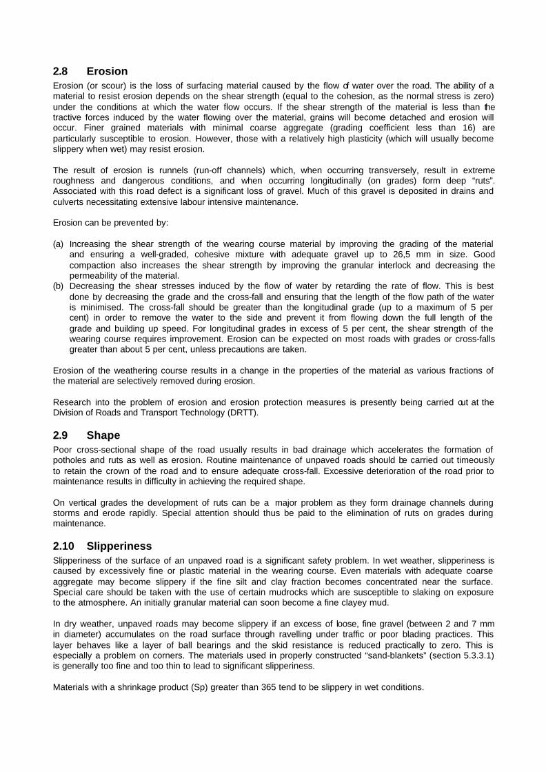
2.4 Corrugations Corrugations are one of the most disturbing defects of unpaved roads causing excessive roughness and poor vehicle directional stability. Their cause has been debated for decades but consensus has now been reached on the “forced oscillation theory” (Figure 1) as the predominant mechanism. Recent research in South Africa has produced evidence to confirm this (Paige-Green, 1989a). The theory is based on initiation of wheel bounce by some irregularity in the road (or possibly even worn suspension components such as shock-absorbers). The process results in kick-back of non-cohesive material, followed by compression and redistribution of the wearing course as the wheel regains contact with the road. Corrugations can be either “loose” or “fixed” (Figure 2). Loose corrugations consist of parallel crests of loose, fine-sandy material at right angles to the direction of travel. Fixed corrugations on the other hand consist of compacted, parallel crests of hard, fine-sandy material. The troughs are compacted by the force of the wheel regaining contact with the ground. Loose corrugations are easily removed by blading, whereas fixed corrugations need cutting or even tining with the grader before the material is respread. The wavelength of the corrugations is dependent on the modal speed (i.e. most frequently occurring speed) of the vehicles using the road, with longer wavelengths formed by faster traffic. Numerous observations from all over southern Africa indicate that the wavelength of the corrugations in centimetres is approximately numerically equal to the modal speed of the vehicles in km/h.

(a) Wheel in contact with road
(b) Wheel losing contact with road
(c) Wheel regains contact with road
FIGURE 1 The “forced oscillation theory” for the formation of corrugation. (After Heath and
Robinson, 1980).

Typical “loose” corrugations with uncompacted crest
Typical “fixed” corrugations with compacted crest
FIGURE 2 Examples of loose and fixed corrugations Only low plasticity materials corrugate significantly, especially those with a high sand and fine-gravel fraction. However, many roads with gravels having plasticity indices of up to 9 have produced corrugations. These form when the material is continually spread from the sides of the road back onto the road during grader maintenance. This material is usually deficient in binder (most of it having been blown away with time as dust) and the material forming the corrugations is non-plastic. Corrugations seldom form to any significant extent during the wet season, as the material is slightly “cohesive” in its wet state through capillary suction and is not adequately mobile to form corrugations. Roads which have very low modal speeds (less than 20 km/h), such as haul roads, do not usually corrugate. Roads susceptible to the formation of corrugations should be inspected regularly in order to programme the necessary maintenance required to avoid the loose corrugations becoming fixed. On many sandy roads, regular grader blading (perhaps as often as once a week) is not economically viable, but simple towed drags have been used successfully for the removal of corrugations. These can be towed behind an ordinary light vehicle (or even a draught animal if necessary) to retain the road roughness at acceptable levels.

Long wavelength (2,5 to 3,0 metres) fixed corrugations (or undulations) at an angle of 45º to the direction of traffic are found on some roads. These are caused by graders and, once formed, are not removed by normal grading. The best way to remove them is by rotating the grader blade through 90º or extending the blade from the side of the grader and keeping the grader on the shoulder or an uncorrugated portion of the road.
2.5 Ruts Ruts are parallel depressions of the surface in the wheel tracks. They may form as a result of deformation (compaction) of the subgrade, compaction of the wearing course or loss of gravel from the wearing course. Under local conditions rutting is usually insignificant in terms of the overall unpaved road performance. The probable reason for this is the typically strong, free-draining, sandy subgrade prevalent over much of southern Africa, as well as the deep water tables. Ruts pose potential problems as they tend to retain rain water which softens the wearing course and allows deformation under traffic. Routine blading of unpaved roads replaces gravel in the ruts and simultaneously compensates for any subgrade deformation which may have occurred. The material graded into the ruts is generally compacted only in a moist condition. However, after grading, no definite wheel tracks are visible and ruts often begin to form at a slight distance from the previous ones. This allows time for rehabilitation. The main cause of rutting in southern Africa is the ravelling of low-cohesion material under traffic movement. A secondary cause is the deformation of highly cohesive wearing course materials under traffic. Both of these require a different gravel if the rut formation is such that maintenance becomes excessively costly. Excessively wide roads lead to the formation of definite ruts in both directions which tend to be deeper than those on roads of normal width. The probable reason is that no lateral movement of vehicles is necessary when they pass from both directions and all the vehicles travelling in each direction thus consistently travel in the clearly demarcated ruts.
2.6 Cracks Cracks per se are not a major problem on unpaved roads but bad cracking may lead to the formation of potholes. Cracking of the wearing course (which usually occurs only during the dry season) is the result of the plasticity being too high or the material being very fine-grained (e.g. dolomitic wad). The materials which crack badly also tend to become slippery when wet and could be avoided by following the guidelines in section 3.3.1. Certain highly cracked roads with 100 to 150 mm diameter cracked blocks were found to break up under traffic and to form potholes.
2.7 Ravelling The generation of loose gravel under traffic, termed ravelling, is a significant economic and safety problem. Loose gravel may be distributed over the full width of the road but more frequently is concentrated in windrows between the wheel tracks or alongside the travelled portion of the road. The major problems with roads susceptible to ravelling are:
the windrows are a safety hazard; stones from the loose gravel may damage vehicles or windscreens; the rolling resistance of the vehicle is increased by loose material with concomitant increases in fuel consumption and vehicle operating costs; problems with lateral drainage of the road may be caused by windrows of loose material
Ravelling is mainly caused by a deficiency of fine material (and hence cohesion), a poor particle size distribution (e.g. skip grading) in the wearing course gravel and inadequate compaction. Materials with a grading coefficient (Gc: product of the difference in percentage passing 26,5 mm and 2,0 mm sieves and the percentage passing the 4,75 mm sieve expressed as a percentage) in excess of 34 and/or a shrinkage product (Sp) of less than 100 are particularly prone to ravelling. Ravelling is generally worse in the dry season than in the wet season when capillary suction results in some “cohesion”. Fine material can often be blended with the gravel to increase cohesion. A good degree of moist compaction can also be used to cut down ravelling.
2.8 Erosion Erosion (or scour) is the loss of surfacing material caused by the flow of water over the road. The ability of a material to resist erosion depends on the shear strength (equal to the cohesion, as the normal stress is zero) under the conditions at which the water flow occurs. If the shear strength of the material is less than the tractive forces induced by the water flowing over the material, grains will become detached and erosion will occur. Finer grained materials with minimal coarse aggregate (grading coefficient less than 16) are particularly susceptible to erosion. However, those with a relatively high plasticity (which will usually become slippery when wet) may resist erosion. The result of erosion is runnels (run-off channels) which, when occurring transversely, result in extreme roughness and dangerous conditions, and when occurring longitudinally (on grades) form deep “ruts”. Associated with this road defect is a significant loss of gravel. Much of this gravel is deposited in drains and culverts necessitating extensive labour intensive maintenance. Erosion can be prevented by: (a) Increasing the shear strength of the wearing course material by improving the grading of the material
and ensuring a well-graded, cohesive mixture with adequate gravel up to 26,5 mm in size. Good compaction also increases the shear strength by improving the granular interlock and decreasing the permeability of the material.
(b) Decreasing the shear stresses induced by the flow of water by retarding the rate of flow. This is best done by decreasing the grade and the cross-fall and ensuring that the length of the flow path of the water is minimised. The cross-fall should be greater than the longitudinal grade (up to a maximum of 5 per cent) in order to remove the water to the side and prevent it from flowing down the full length of the grade and building up speed. For longitudinal grades in excess of 5 per cent, the shear strength of the wearing course requires improvement. Erosion can be expected on most roads with grades or cross-falls greater than about 5 per cent, unless precautions are taken.
Erosion of the weathering course results in a change in the properties of the material as various fractions of the material are selectively removed during erosion. Research into the problem of erosion and erosion protection measures is presently being carried out at the Division of Roads and Transport Technology (DRTT).
2.9 Shape Poor cross-sectional shape of the road usually results in bad drainage which accelerates the formation of potholes and ruts as well as erosion. Routine maintenance of unpaved roads should be carried out timeously to retain the crown of the road and to ensure adequate cross-fall. Excessive deterioration of the road prior to maintenance results in difficulty in achieving the required shape. On vertical grades the development of ruts can be a major problem as they form drainage channels during storms and erode rapidly. Special attention should thus be paid to the elimination of ruts on grades during maintenance.
2.10 Slipperiness Slipperiness of the surface of an unpaved road is a significant safety problem. In wet weather, slipperiness is caused by excessively fine or plastic material in the wearing course. Even materials with adequate coarse aggregate may become slippery if the fine silt and clay fraction becomes concentrated near the surface. Special care should be taken with the use of certain mudrocks which are susceptible to slaking on exposure to the atmosphere. An initially granular material can soon become a fine clayey mud. In dry weather, unpaved roads may become slippery if an excess of loose, fine gravel (between 2 and 7 mm in diameter) accumulates on the road surface through ravelling under traffic or poor blading practices. This layer behaves like a layer of ball bearings and the skid resistance is reduced practically to zero. This is especially a problem on corners. The materials used in properly constructed “sand-blankets” (section 5.3.3.1) is generally too fine and too thin to lead to significant slipperiness. Materials with a shrinkage product (Sp) greater than 365 tend to be slippery in wet conditions.
The only cure for roads which are slippery when wet is to regravel with a better gravel (i.e. having a lower shrinkage product), and for those which are slippery when dry to improve the blading operation. Warning signs should be prominently displayed on slippery roads. The practice of adding a gravel or sand to the existing material is recommended in some manuals but this does not avoid the possibility of the fine material migrating to the surface. A significant quantity of gravel is usually required to reduce the percentage passing the 0,075 mm sieve sufficiently to affect the shrinkage product.
2.11 Impassibility (trafficability) The primary objective of importing a wearing course gravel during the construction of an unpaved road is to provide an all-weather surface. This objective is not met if the material becomes impassable in wet weather. This is often a particular problem with earth roads where in situ materials are used. It is generally considered that an adequately high material strength (in terms of the California Bearing Ratio (CBR)) will provide a trafficable surface under all conditions. Values for the CBR recommended in specifications vary from a soaked value of 15 at 95% Proctor compaction (probably about 40 at Mod AASHO effort) up to a value of 60 at 98% Mod AASHO compaction (Netterberg and Paige-Green, 1988). Very little evidence for the failure of unpaved roads caused by inadequate material strength at depth has been observed. The passability is, however, a function of the shear strength in the top layer of the wearing course. As with erosion, if the tractive stresses exerted by the rotating wheels exceed the shear strength (or cohesion) of the material at the surface, shearing will result. Repeated shearing (churning) will result in the road becoming impassable in that area. Local experience has indicated that a modified CBR of 15 at the expected field density and moisture condition is adequate to prevent well-shaped roads from becoming excessively churned up, except in those regions where long spells (up to 7 days) of wet weather occur and under excessive heavy traffic. Sufficient coarse gravel in the upper layers assists with the interlock of the material and provides this strength. It must however, be noted that gravel coarser than 19 mm was excluded from the CBR test material during this project (crushing of the plus 19 mm material according to Method A7 (NITRR, 1979; 1986) results in a totally unworkable grading for typical wearing course materials) and the result obtained is therefore often not a true reflection of the in situ material strength.
2.12 Gravel loss Although the loss of the wearing course material from the road surface under traffic and climatic conditions (rain and wind) is inevitable, the replacement of this lost material is the most costly maintenance operation. Material which ravels is most likely to result in a high gravel loss. Although the major contributor to the gravel loss is the traffic (Section 3.2.3), significant reductions in gravel loss can be obtained by selecting material with a suitably high plastic factor (PF greater than 500) and percentages passing the 26,5 mm sieve (Section 3.2.3). Well-graded and well-compacted gravels resist gravel loss better than materials deficient in either fine or coarse fractions. Erosion should be reduced as far as possible to avoid excessive gravel loss on longitudinal grades.
2.13 Excessive loose material Excessive loose material in the form of non-compacted material across most of the road width or thick windrows next to the trafficked portion of the road or between the wheel-tracks results in increased road user costs and unsafe driving conditions. This problem is typically a symptom of inadequate or ineffective grader maintenance and may be exacerbated by materials which are particularly susceptible to ravelling (Section 2.7).
3 DESIGN OF UNPAVED ROADS
3.1 Geometric design The geometric design is not considered in any detail in this manual. Guidelines on geometric standards for unpaved roads (specifically in developing areas) are discussed in various documents such as Nyasulu (1988). The road alignment should, however, be adapted to the prevailing conditions. A different philosophy

should be applied to roads opening up areas and those which are likely to be forerunners of paved roads. It is not usually economically feasible to construct deep cuts, high fills or large radius horizontal curves in mountainous areas in order to accommodate the recommended geometric standards. Economic constraints usually dictate that the geometric standards have to be compromised (with speed restrictions or warning signs where necessary). Where possible, construction along watersheds is recommended. A significant problem in southern Africa is the occasional construction of unnecessarily wide unpaved roads (roads with travelled ways of up to 10 m and up to 14 m between shoulder breakpoints have been recorded). This results in unnecessarily excessive surfacing gravel and grader maintenance being required and a rapid loss of shape of the road. On the other hand, excessively narrow roads result in deep rutting, poor safety standards and high gravel losses. The total gravelled width of the road should be about eight metres for most unpaved roads carrying between 50 and 200 vehicles per day. This can be reduced for roads carrying less than 50 vehicles per day and in mountainous terrain and should be increased to 9 m for roads carrying more than 200 vehicles per day or those carrying large vehicles such as coal or sugarcane trucks. The width and alignment of unpaved roads should generally be appropriate to the prevailing traffic, climate and topography and geometric standards for unpaved roads should be flexible enough to provide for this. Care should, however, be taken to create a speed environment with matching geometric elements to eliminate the element of surprise and avoid unsafe conditions to which driver awareness is not sensitive.
3.2 Thickness design The structural design of paved roads has, in the last two or three decades developed into a highly sophisticated branch of engineering. The design of unpaved roads, on the other hand, has received minimal attention. Unpaved roads may form an initial stage towards paved roads and designs should take this into consideration. No scientific structural design procedure for unpaved roads is presently used regularly in southern Africa. The Maintenance and Design System (MDS) (Visser, 1981) incorporates work carried out at the Waterways Experiment Station (Barber et al, 1978) where models to predict the rut depth from material properties, traffic and surfacing thickness were developed. Unfortunately no design thickness models were included, but Visser (1981) transposed the variables in the models to predict the design thickness. The transposed model produced a more realistic cover thickness than the models developed earlier, indicating that for subgrade CBR values greater than 5 (at Proctor compaction) with 150 mm of surfacing material (Proctor CBR greater than 30) some 10 000 truck repetitions would be required to produce a rut of 75 mm. The failure criteria of 75 mm deep ruts is considered excessive for typical rural roads in southern Africa, especially in the wetter eastern areas where the ruts may trap water for lengthy periods. This increased rut depth is a short-fall affecting the applicability of most overseas work to local conditions. Although the rut would normally be removed by routine grader maintenance, a significant proportion of it would be in the form of subgrade deformation resulting in a loss of wearing course material. The actual gravel loss which occurs with time and under traffic results in a dynamic situation and the optimum wearing course thickness is therefore effectively valid for only a short period of time. Based on this consideration and extensive observations and measurements carried out locally, a structural design procedure for use under southern African conditions has been developed. The design thickness (T in mm) recommended for imported gravel wearing courses is therefore:
? ?dpt LGLCtT ???
???
?? ??? 1001 (1)
where t = minimum thickness required for subgrade protection (mm)
Ct = traffic induced compaction (%) GLp = predicted annual gravel loss (mm)
Ld = design life of road or regravelling frequency (years)
3.2.1 Minimum thickness required for subgrade protection (t) The minimum thickness required for subgrade protection can generally be excluded from Model 1, certainly for subgrade materials with a field CBR in excess of 5%. The value for the in situ CBR can be easily determined using the Dynamic Cone Penetrometer (DCP) (Kleyn, 1984). A DCP penetration of more than about 32 mm per blow indicates that the CBR is 5 per cent or less for most subgrade soils. Southern African

subgrades typically consist of sandy materials, unaffected by moisture because of the deep water tables. These sands, although relatively strong in themselves, require confinement to mobilise their strength and are thus not suitable for wearing courses. It has been observed that under these typical South African material and environmental conditions and applied loads, no minimum thickness is required for subgrade protection, i.e. the subgrade is unlikely to be overstressed. For subgrades with field CBR values (i.e. at expected in situ density and moisture content) of less than 5 % it is recommended that a nominal 50 mm of wearing course material (t in Equation 1) be used for subgrade protection until further research indicates otherwise. This is in addition to the thickness required for the other two parameters in Equation 1. The relationship between elastic and plastic behaviour of the subgrades, the validity of elastic analysis for this type of work and acceptable limits for the maximum vertical compressive strain require clarification before the sub-grade behaviour can be fully categorised. Routine grader maintenance of unpaved roads generally results in surface correction of any subgrade deformation. It is of course recommended that a formation of at least 300 mm thickness be constructed of material with an acceptable CBR strength (=5%), which also serves as subgrade protection. Recent developments in the field of geotextiles and Geogrids has led to their successful use in reinforcing unpaved roads over very weak subgrades (Giroud and Noiray, 1981; Giroud et al, 1984; Hausmann, 1987). These are not discussed further in this report, but can be considered for the rare occurrence of very weak subgrades in special cases (CBR always less than about 3%). If they are used, the wearing course should not be allowed to become less than 100 mm thick in order to provide some protection from wheel contact, grader maintenance, exposure to the atmosphere and ultra-violet light.
3.2.2 Traffic induced compaction (Ct) Wearing courses which have been compacted with a nominal number of passes of a grid-roller can lose up to 30 per cent of the constructed thickness within a short period due to traffic compaction (Paige-Green, 1989). It is therefore important to ensure adequate compaction or allow for the loss in pavement thickness caused by traffic compaction in the thickness design. This is especially relevant when the materials are relatively dry of optimum moisture content during grid-rolling, as the air voids are high and traffic compaction will occur rapidly. If a density equivalent to that at about 95% Mod AASHO effort is achieved, the air voids are about 5 per cent, but at a compaction moisture content 25 per cent dry of optimum (i.e. about 75 per cent of optimum moisture content), the density is reduced by about 10 per cent and the air voids may be up to 20 per cent. This air void percentage will decrease rapidly under traffic and an estimate of this compaction needs to be obtained. The following can be used as approximate estimates of the potential traffic compaction:
Compaction during construction
Moisture content during construction
Potential loss of gravel thickness
3 passes of a grid roller about OMC 10% 3 passes of a grid roller dry of OMC 20% 3 passes of a pneumatic tyred roller About OMC 5% Local experience and field trials may be necessary to quantify these estimates more accurately. The compaction which occurs during normal construction should not be neglected and up to about 30 per cent more bulk material is required to allow for this and still produce the required thickness.
3.2.3 Predicted annual gravel loss (GLp x Ld) The annual gravel loss (AGL expressed in mm) can be predicted with a high degree of confidence to within 11 mm per year (Paige-Green, 1989a) by the following:
? ?? ?260474,00014,0367.0260006,00027,0059,065,3 PPFNPNADTAGL ?????? where ADT = average daily traffic
N = Weinert N-value P26 = Percentage passing the 26,5 mm sieve* PF = product of plastic limit and percent passing 0,075 mm sieve*
* grading analysis carried out according to Appendix A.

A BASIC computer program listing of this model which calculates the annual gravel loss and the predicted regravelling frequency for any given regravelling thickness is included as Appendix B. The product of the annual gravel loss and the design period will indicate the material which will be lost by erosion and traffic whip-off over the design life of the road. The regravelling frequency predicted from Appendix B indicates the time before total loss of the imported wearing course will occur. It is important to regravel the road before the subgrade is exposed in order to avoid unnecessary maintenance problems. Potholes form rapidly if the subgrade is exposed.
3.3 Material selection Numerous specifications are currently available for the selection of materials for unpaved road wearing courses in southern Africa (Netterberg et al, 1988).These have been compared with the properties of a number of in-service roads in southern Africa and found to be generally lacking in their ability to predict the performance of roads (Paige-Green, 1989b). Many satisfactory materials are rejected while many materials which perform poorly are deemed acceptable. Performance-related specifications have been developed for southern African conditions (Paige-Green, 1989a). These are based on the sampling, testing and monitoring of the performance of 110 sections of unpaved road in southern Africa over a period of more than three years (Paige-Green, 1989a) as well as previous research on this topic. The importance of material durability in unpaved roads was found not to be important during the experiment. However, mudrocks in certain areas may be subject to rapid disintegration and should be investigated by the 5-cycle wet-dry test (Venter, 1989). Other tests such as the Los Angeles Abrasion may be useful as indicators of excessively soft or hard material which may break down under traffic or will not break down under a grid-roller, respectively.
3.3.1 Rural Roads The following specifications for materials for unpaved rural roads are recommended (Table 1):
TABLE 1 Recommended material specifications for unpaved rural roads Maximum size: 37,5 mm Oversize index (IO)a: = 5 per cent Shrinkage product (SP)b: 100 - 365 (max. of 240 preferable) Grading coefficient (GC)c: 16 - 34 CBR: = 15 at = 95 per cent Mod AASHO compaction and OMCd a IO = Oversize Index (per cent retained on 37,5 mm sieve) b SP = Linear shrinkage x per cent passing 0,425 mm sieve c GC = (Per cent passing 26,5 mm – per cent passing 2,0 mm) x per cent passing 4,75 mm/100 d tested immediately after compaction

FIGURE 3 Relationship between shrinkage product, grading coefficient and performance of unpaved
wearing course gravels The specifications for shrinkage product and grading coefficient are shown schematically in Figure 3. The following conclusions can be drawn about each zone as defined in the figure:
A - Materials in this area generally perform satisfactorily but are finely graded and particularly prone to
erosion by water: they should be avoided if possible, especially on steep grades and sections with steep cross-falls and super-elevations. Most roads constructed from these materials perform satisfactorily but may require periodic labour-intensive maintenance over short lengths and have high gravel losses due to water erosion.
B - These materials generally lack cohesion and are highly susceptible to the formation of loose material
(ravelling) and corrugations. Regular maintenance is necessary if these materials are used and the roughness is to be restricted to reasonable levels.
C - Materials in this zone generally comprise fine, gap-graded gravels lacking adequate cohesion,
resulting in ravelling and the production of loose material. D - Materials with a shrinkage product in excess of 365 tend to be slippery when wet. E - Materials in this zone perform well in general, provided the oversize material is restricted to the
recommended limits. The specifications accept a number of materials which are likely to be unacceptably dusty, but many materials which perform well would be eliminated by lowering the shrinkage product to 240. This was considered unnecessarily harsh for rural roads. Attempts should be made, however, to locate materials with a shrinkage product of less than 240 as far as possible. By plotting the shrinkage and grading properties of a potential unpaved wearing course gravel on Figure 1, an indication of the suitability and any potential problems will be obtained. However, personal judgement should be used. In flat, dry areas, materials falling into zones A and D may be acceptable if the site-specific potential to erode or become slippery is not excessive.
3.3.2 Urban Roads The following specifications are recommended for unpaved roads in urban areas (Table 2):

TABLE 2 Recommended material specifications for unpaved roads in urban areas Maximum size: 37,5 mm Oversize index (IO): 0 Shrinkage products (SP): 100 - 240 Grading coefficient (GC): 16 - 34 CBR: = 15 at = 95 per cent Mod AASHO compaction and OMC In comparison with the limits for rural roads it can be seen that the limits for the oversize index have been reduced to eliminate stones whilst the shrinkage product has been reduced to a maximum of 240 to reduce the dust as far as practically possible. This lower limit reduces the probability of unacceptable dust from about 70 per cent to 40 per cent.
3.3.3 Haul Roads The material selected for an unpaved haul road (such as a mine, forestry or agricultural road) should preferably have the following properties (Table 3):
TABLE 3 Recommended material specifications for unpaved haul roads Maximum size: 75 - 100 mm Oversize index (IO): = 10 per cent Shrinkage product (SP): 100 - 365 (max preferably < 240) Grading coefficient (GC): 16 - 34 CBR: = 15 at = 95 per cent Mod AASHO compaction and 4 days’ soaking An increase in the maximum size and oversize index (within limits) is allowable as haul-vehicles generally have large tyres (often with lower tyre-pressures) and usually travel at slower speeds than vehicles on rural and urban roads. Road user costs will therefore not be as sensitive to stoniness. A soaked CBR is recommended in order to allow for the greater traction forces exerted by the heavily-loaded vehicles usually associated with haul roads.
4 CONSTRUCTION
4.1 Subgrade preparation Many unpaved roads, however lightly trafficked at the time of construction, will with the passage of time capture more traffic and increase in use (and importance) as the local population increases. They may eventually be upgraded to higher standard unpaved roads or even relatively lightly trafficked paved roads. Good preparation of the subgrade for a new unpaved road is therefore extremely important as this will often be the subgrade for a large part of the future improved road. Initially the subgrade should be cleared of bush and trees over the full width of the road prism. All vegetable matter and organic soil should be removed by grader or bulldozer from the road prism. The road bed should be ripped and mixed, sprayed with water to about Optimum Moisture Content (OMC) and then be compacted to a density of at least 90% Mod AASHO (about 95% Proctor) maximum dry density. Nuclear density techniques or a quick, simple sand replacement test (Cernica, 1980) may be economically viable for density testing of unpaved roads. Because of the natural variability of subgrade (and wearing course) materials, the normal time consuming sand-replacement density tests are seldom cost-effective. It is thus recommended that a number of quick tests be carried out and the average density considered. Adequate subgrade compaction reduces the possibility of subgrade deformation and reduces the permeability and strengthens the subgrade. The subgrade should then be smoothed and shaped with a suitable cross-fall (about 2 per cent). Material of at least subgrade quality (CBR = 5%) should be used to build up the formation to a height of not less than 300 mm above the natural ground level in flat terrain. This material can usually be obtained during the construction of side drains parallel and on each side of the road and mitre drains to remove water from the side drains. The drains should be deep and wide enough to remove all the expected surface water during wet periods from the road and its adjacent areas without ponding or excessive erosion. In flat areas, the formation should be high enough to allow the placement of drainage structures (usually pipes) at adequate depths beneath the wearing course. It is important that the construction of the formation does not interfere with the natural drainage of the surrounding area and cause ponding. The material used for the formation

should be slightly plastic with a plasticity index of about 4 in order to provide a stable platform for construction of the wearing course. Other material from a borrow pit may be required to build up the formation. Once adequate material has been dumped on the subgrade, the formation should be compacted at about OMC to a density of 90% Mod AASHO and smoothed and shaped as for the subgrade. It is important that the formation level is smooth and has an adequate cross-fall to ensure that any water that soaks through the wearing course does not pond at formation level, should a permeability differential exist. The wearing course is placed directly on the formation in most unpaved roads, although “subbases” may be used if the subgrade is poor or large numbers of heavy vehicles are likely to use the road.
4.2 Gravel operations The location, winning and transportation of wearing course gravels is one of the most expensive operations associated with the development of unpaved roads. It is therefore important that the optimum material be located nearby and used to maximum advantage. Materials location is a science in itself and should follow a logical process and not the random exploration that is often done (Netterberg, 1985). The materials should be located by either experienced field staff or geotechnical experts, in such a manner that they comply with the appropriate specifications recommended in Section 3. These specifications, like most material specifications (e.g. TRH 14 (NITRR, 1985a)), apply to the materials after processing and compaction. It is important to demarcate the extent of the suitable materials in the borrow pit clearly and ensure that material is only obtained from this area. Similarly, the depth of excavation should be carefully controlled so as not to excavate into less weathered or different material (often with significantly different properties) at greater depths. Stockpiles should be kept as low as possible to reduce segregation of the material (Ferry, 1986). The gravel operations should be carried out in a manner which ensures a consistent gravel of the required quality. Optimally, the material should be processed to remove or reduce oversize in the borrow pit as far as possible. One such device for doing this is a “Grizzly”. This is a cheap, portable method of sieving out oversize material using a frame supporting a screen of the required aperture, which can be used in the borrow pit. Although it may slow down material production in the borrow pit, it is capable of a high production rate (Ferry, 1986) and should be used wherever possible. The material should be excavated and processed in the borrow pit before removal of the gravel to the construction site commences. The use of a grid roller to break down oversize material on the road is not always successful. Adequate supervision and the correct use of the roller is essential for satisfactory results. Certain materials such as decomposed dolerite and andesite may disintegrate adequately, but often corestones of hard unweathered material and pedocrete boulders survive the grid rolling and result in excessive roughness of the completed road. If a significant portion of the material is oversize, a portable crusher should be used to reduce this to the maximum size specified. It may be economic in some cases to windrow the oversize materials in or next to the borrow pit, and reduce them with a mobile hammer-mill (e.g. Rockbuster). Although mobile hammermills can be used on the material dumped on the road, it is recommended that they be used at the borrow pit in order to reduce the transportation of oversize material, which is not broken down by the hammermill. It has been shown elsewhere (Beaven, 1987) that for roads carrying over 50 vehicles per day it is cost-effective (in terms of the vehicle operating and maintenance costs) to crush oversize material to pass a 37,5 mm sieve. The most economic means of removing oversize in borrow pits with only a limited quantity of large stones is manually, by hand-picking. If blending is necessary to achieve the required shrinkage product or alter the particle-size distribution of the gravel, this can be done in the borrow pit if the sources of gravel are in close proximity, but is usually most effective on the road. Careful supervision of the dumping and mixing of the materials is necessary to ensure that the correct proportions are combined and mixing is complete.

Where possible the material should be moistened in the borrow pit before being hauled to the road. This reduces segregation during hauling and assists with the compaction of the material. Construction in the wet season permits the use of rainfall to provide this moisture. Some materials such as mudrocks and highly weathered basic igneous rocks which slake on exposure to the atmosphere often require stockpiling for a period varying from a few days to a few weeks to achieve the required breakdown. These should be allowed to break down in the borrow pit and must not be left on the side of the road being regravelled while they disintegrate (for obvious safety reasons). Materials which slake to a fine powdery material are undesirable for wearing courses and should be avoided. The direction of transportation of the gravel should be such that the newly constructed road is not trafficked by the construction traffic. If the road is compacted as previously recommended, trafficking by construction vehicles results in more damage to the road (ravelling and potholing) than the benefits gained from further compaction. If the compaction is minimal (not recommended) the passage of the construction traffic may be beneficial. One of the main problems with the construction of unpaved roads is the lack of supervision. Greatly improved unpaved roads would result from close supervision by experienced personnel during the borrow-pit working and actual construction. The techniques described in this section apply equally to the regravelling operation.
4.3 Wearing course construction Good construction practices for wearing courses will:
provide the correct thickness of material; provide adequate compaction; provide a smooth finish with a good cross-sectional shape.
4.3.1 Thickness It is important that the material be dumped on the road at the correct spacing to provide for the expected thickness of gravel after spreading and compaction. If the constructed thickness is incorrect, the management of the maintenance of the road network will be disrupted as premature regravelling may be necessary or the road may need a thinner layer of gravel when being regravelled. Both of these variations affect the budgeting requirements. The thickness must be as consistent as possible over the length of the link to avoid total loss of gravel over portions of the link only.
4.3.2 Compaction Good compaction produces a tightly bound gravel with optimum particle interlock, minimum permeability and porosity and significantly increased strength. The importance of adequate moist compaction has been clearly shown by Poolman (1988) who found that a high degree of moist compaction resulted in a road with a lower roughness than similar materials which were poorly compacted in a dry condition. The roughness deterioration was much slower and gravel loss and dust emission were significantly reduced. A poor degree of compaction results in a low density, permeable material which ravels easily and is highly moisture sensitive. Deep rutting, compaction under traffic, potholing, corrugations and passability problems under soaked conditions are common problems with poorly compacted material. The initial traffic-induced compaction and increased gravel loss again interfere with the maintenance management strategy for the road. In order to take advantage of the moisture added to the material before hauling, the material should be dumped, spread and compacted before a significant quantity of the water has evaporated. This requires careful project planning and management. Construction during the wet season results in additional moisture being available (from rain) and often lower evaporation. Numerous commercial proprietary compaction aids are available in southern Africa. Many of these appear to be suitable only for certain material types, while others have little benefit or are not cost-effective. Potential
use of these should be preceded by laboratory investigations concerning their suitability or trial sections where possible.
4.3.3 Finish and shape The roughness of a road is one of the most important factors influencing vehicle operating cost, affecting every contributor except depreciation (Harral et al, 1975). It is important therefore to make use of competent grader operators who can provide a smooth, well-finished riding surface. A good surface after construction can be maintained to a much better standard than a poorly finished surface. The cross-section and shape of the road should ensure a definite crown with a cross-fall of about 4 per cent (not more than 5 per cent). Large stones (greater than 50 or 75 mm), which have found their way into the gravel, should be removed (manually if necessary) and discarded at a distance from the road to ensure that they are not bladed onto the road during routine blading or drain clearing. A common problem is the use of oversize material which is repeatedly rolled (usually with a grid roller) until it is embedded well into the layer and often, even the subgrade. In a short time these stones and boulders protrude from the surface, causing a rapid deterioration in the roughness and significant maintenance problems. Construction crews should, where possible, be trained to refrain from this practice.
4.4 Drainage Unpaved roads are totally exposed to the elements and rainfall can result in significant maintenance problems. The importance of good drainage cannot be overemphasised. The moisture content of an unpaved road is one of the few causes of problems which can be controlled by the road maintenance team. The water in an unpaved road can only come from two sources:
surface water from precipitation (including flooding); subsurface water from high water tables, seepage, springs and capillary suction.
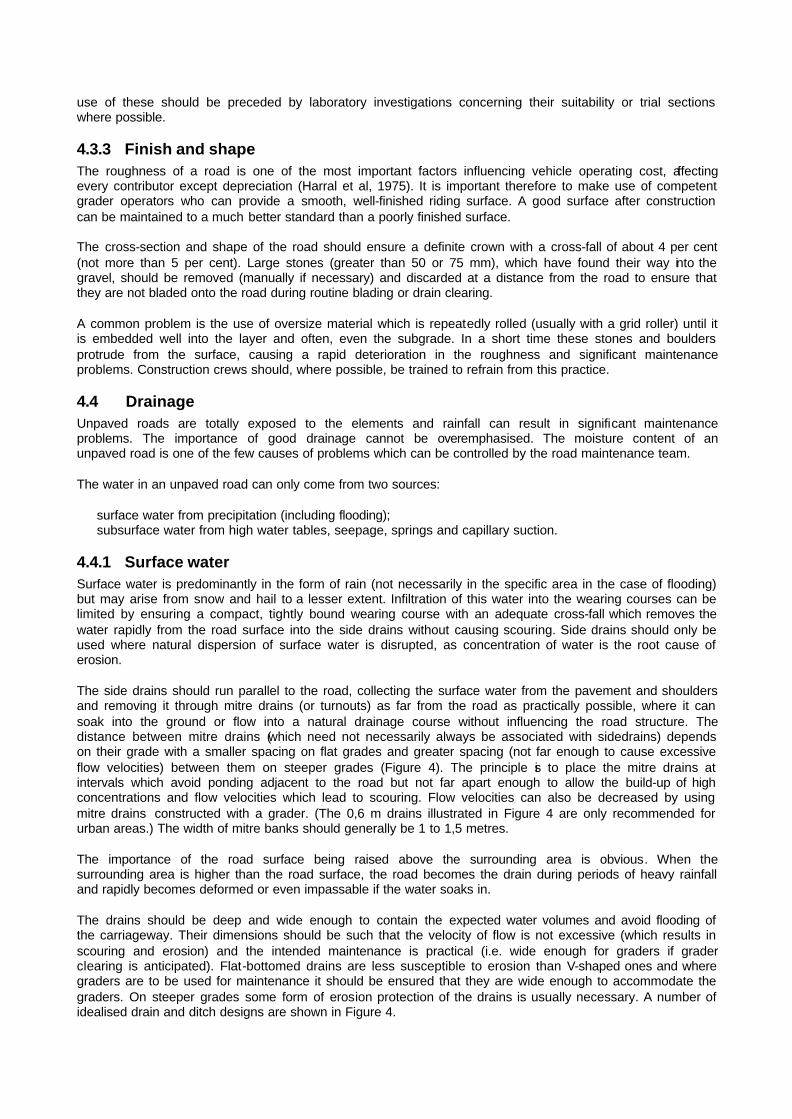
4.4.1 Surface water Surface water is predominantly in the form of rain (not necessarily in the specific area in the case of flooding) but may arise from snow and hail to a lesser extent. Infiltration of this water into the wearing courses can be limited by ensuring a compact, tightly bound wearing course with an adequate cross-fall which removes the water rapidly from the road surface into the side drains without causing scouring. Side drains should only be used where natural dispersion of surface water is disrupted, as concentration of water is the root cause of erosion. The side drains should run parallel to the road, collecting the surface water from the pavement and shoulders and removing it through mitre drains (or turnouts) as far from the road as practically possible, where it can soak into the ground or flow into a natural drainage course without influencing the road structure. The distance between mitre drains (which need not necessarily always be associated with sidedrains) depends on their grade with a smaller spacing on flat grades and greater spacing (not far enough to cause excessive flow velocities) between them on steeper grades (Figure 4). The principle is to place the mitre drains at intervals which avoid ponding adjacent to the road but not far apart enough to allow the build-up of high concentrations and flow velocities which lead to scouring. Flow velocities can also be decreased by using mitre drains constructed with a grader. (The 0,6 m drains illustrated in Figure 4 are only recommended for urban areas.) The width of mitre banks should generally be 1 to 1,5 metres. The importance of the road surface being raised above the surrounding area is obvious. When the surrounding area is higher than the road surface, the road becomes the drain during periods of heavy rainfall and rapidly becomes deformed or even impassable if the water soaks in. The drains should be deep and wide enough to contain the expected water volumes and avoid flooding of the carriageway. Their dimensions should be such that the velocity of flow is not excessive (which results in scouring and erosion) and the intended maintenance is practical (i.e. wide enough for graders if grader clearing is anticipated). Flat-bottomed drains are less susceptible to erosion than V-shaped ones and where graders are to be used for maintenance it should be ensured that they are wide enough to accommodate the graders. On steeper grades some form of erosion protection of the drains is usually necessary. A number of idealised drain and ditch designs are shown in Figure 4.

If the natural topography is such that water will disperse by itself and drains can be avoided, significant cost-savings can be effected and potential problems avoided. It is important that the road structures do not interfere with the cross drainage of the area. Adequate means of cross drainage such as culverts are necessary with careful attention being paid to their size and inlet and outlet control.
4.4.2 Subsurface water Subsurface water is derived mainly from high ground-water levels (temporary or permanent) and seepage, but occasionally springs beneath the road may be encountered, especially in cuttings. Capillary rise of water from relatively high ground-water levels may occur in clayey soils. Subsurface drainage problems are usually manifested as damp areas on the road surface which eventually result in potholes. The remedial actions may require subsurface drains if the water is due to high water tables or capillary suction, or cut-off side drains when the water seeps from areas adjacent to the road. These are, however, not recommended as they are expensive and often require careful maintenance. The use of rock-fill embankments is a possible alternative, but geotechnical assistance should be obtained to identify the source of the water and propose remedial measures in these cases.
FIGURE 4 Ditches and drains

5 MAINTENANCE
5.1 Maintenance management The annual expenditure on maintenance of unpaved roads in southern Africa is of the same order as that of paved roads. The management of maintenance is therefore necessary to maximise the benefit from the available finance. Maintenance management systems should provide answers to questions such as the following (Visser, 1986): ?? What budget is required? ?? How many graders and staff are required? ?? How often should each road be bladed? ?? What is the resultant level of serviceability? ?? What volume of gravel needs to be replaced annually? ?? Which roads should be upgraded to bituminous standard? Presently the management of the maintenance of unpaved roads is minimal over much of southern Africa. The frequency of grader maintenance tends to be based primarily on the number of graders available with a systematic type of programme being followed to utilise each grader to maximum advantage. The importance of the maintenance management of unpaved road networks has been recognised in the last few years and a number of authorities are presently developing maintenance management systems for unpaved roads to suit their specific needs. Recent developments in the field of maintenance management systems have resulted in the production of computer programs which optimise the maintenance program on the basis of the total transport costs. The Maintenance and Design System (MDS) (Visser, 1981) is one such program. The models used to predict roughness progression and gravel loss were developed from performance related studies in Brazil (Visser, 1981). New models based on local conditions have been developed (Paige-Green, 1989a) and are included in the updated MDS. The MDS can be used to optimise the grader blading frequency of the road links in a network. Those roads for which it is economically beneficial (in terms of the total cost) to maintain more frequently (because of traffic or material characteristics) are identified. An idealised regravelling frequency of the links is also obtained. An advantage of the MDS is that the annual loss of gravel on a district or network basis is estimated and the amount of gravel which needs to be replaced annually to avoid the development of a backlog of gravel replacement for the district or network as a whole is identified. This can be used beneficially in the budgeting process and avoids periods when unexpectedly large quantities of gravel are suddenly required. Aspects such as “when is it more economical to seal certain roads than maintain them" and "the optimum number of graders required" are also covered by the MDS. For any road management system it is necessary to develop and regularly update an inventory of the important parameters influencing the performance and maintenance requirements. Generally computer-based data-bases are the only effective way to do this on a network basis. It is possible to determine regravelling and blading frequencies for individual links using the simple models developed by Paige-Green (1989a). Although these models were developed for use in the MDS they have been manipulated for use on most Personal Computers and some calculators. The BASIC listings and definition of the input parameters of the models are provided in Appendices B and C. The MDS only indicates the predicted maintenance requirements of a link and does not identify problem areas within the link. Often short lengths of the link may become subjected to bad erosion, potholes, excessive churning of the wearing course or corrugations. These problems can only be identified by detailed inspection and are often best remedied by labour intensive techniques, spot regravelling or low-cost drags. Whichever maintenance management system is selected or devised, the main objective is to rank scientifically the maintenance requirements of the links making up the network on the basis of economics, levels of serviceability (Sec 5.2), available funding, labour and equipment and the skill levels of the staff.

5.2 Levels of serviceability Maintenance requirements and costs are based almost entirely on the required level of serviceability which should be appropriate to the traffic. A level of serviceability acceptable for a remote, rural unpaved road with low traffic would generally be unacceptable for an unpaved feeder road to a densely populated developing area. No guidelines for levels of serviceability for unpaved roads in southern Africa exist at present but the following based on performance criteria could be taken as a basis (Table 4): The maximum roughness is generally used to determine the grader blading frequency in maintenance management systems and can be programmed into the maintenance management system. The level of serviceability should be adapted to the primary use of the road. Important tourist routes or a farm access road over which a fragile product sensitive to extremely rough roads (such as eggs) is to be transported, may be maintained at a level of service higher than that which the traffic dictates, for obvious reasons.
TABLE 4 Definition of levels of serviceability Level of
Serviceability Max Roughness a Required standards
Dustiness b Impassability
1 200 5 Frequently 2 150 4 < 5 days/yr 3 120 4 Never 4 100 3 Never 5 80 3 Never
aa QI (Counts/km) over 10 per cent of the link b See Paige-Green (1988b)
5.3 Practical aspects of maintenance Despite all the programming and time spent on maintenance it is not worth doing if it is not done cost-effectively. The importance of sufficient maintenance carried out by experienced and conscientious machine operators and back-up staff can not be overemphasised. Once the condition of a road deteriorates beyond a certain point, restoration of the road to an acceptable condition can seldom be achieved with routine maintenance and requires a considerable mechanical and labour input. The major categories of maintenance covered in this report are:
roadside maintenance; drainage maintenance; surface maintenance.
5.3.1 Roadside maintenance The roadside is defined (Hudson et at, 1987) as the first 3 m (10 feet) adjacent to the edge of the shoulder or pavement. For local conditions it is considered prudent to define the roadside as the full road reserve (National Research Council, 1979). The main maintenance activity affecting the roadside is bush clearing and grass cutting. This procedure is carried out mainly for safety reasons but also to avoid damage to vehicles from vegetation overhanging the pavement edge and to reduce the fire hazard in some areas. The frequency of this maintenance depends on the relevant level of serviceability and should be adapted for the district under consideration. Areas with a high rainfall and short-radius horizontal and vertical curves (i.e. short sight distances) will require considerably more vegetation control than long straight roads in arid areas. Vegetation control on unpaved road reserves is best carried out manually although mechanised control may be cost-effective in some areas. Collection of litter should also be programmed periodically, especially near built-up areas and on more heavily trafficked and tourist routes. Debris from car accidents, discarded car parts (e.g. exhaust pipes and silencers) which periodically litter the road and dead animals should be removed as soon as possible.

Another roadside maintenance activity which should not be neglected is the repair and prevention of erosion affecting cut and fill slopes and ditches. The most cost effective way of preventing this erosion is the establishment of vegetation. Cuts and fills should be constructed at suitable batters to allow the establishment of vegetation (preferably less than 1 vertical :2 horizontal) with a cut-off drain or catchwater bank just behind the crest of the cut or fill. Should erosion occur, the erosion channels should be back-filled with rocks and grouted if possible. The erosion of drains could also be prevented by a rock lining and some form of obstacle (e.g. rock dams, vegetation) to retard the speed of water flow. Care should be taken with vegetation as the siltation often results in vigorous growth and eventual filling of the drain. Erosion of culvert inlets and outlets is a common problem and control structures, e.g. rock rip-rap or concrete wing-walls may be considered at problem sites. With time the erosion protection measures themselves may require significant maintenance. Most of the roadside maintenance is labour intensive and great scope exists for the contracting of this type of work to local residents in developing rural areas.
5.3.2 Drainage maintenance In both the wetter areas of southern Africa, where prolonged periods of rain occur, and in the more arid areas where high intensity thunder-storms of short duration are common, drainage problems affecting unpaved roads are significant. Many of these can be overcome by improved drainage maintenance. Although the overall drainage systems are usually adequate, with time the drains often become eroded and/or silted up and free drainage of water from the road is impeded. The first significant problem is to remove the bulk of the rain-water from the road surface without causing erosion of the gravel wearing course. For this to occur effectively the surface of the road should be well maintained with a good shape (definite crown), no potholes, deep corrugations or ruts and an adequate cross-fall. Local experience shows that a cross-fall of about 4 or 5 per cent is the optimum which allows adequate run-off without erosion. Longitudinal slopes and cross-falls steeper than about 5 per cent are prone to erosion. On the steep slopes commonly encountered in the eastern areas of southern Africa, erosion is a significant problem and no cost-effective way of avoiding this has been developed as yet. The important drains which require maintenance are the side drains and mitre drains. These should be designed with widths and side-slopes (1:2 or 1:3) which permit ready access of a motorised grader so that maintenance can be carried out during the routine pavement surface maintenance. Graders are, however, adaptable implements and the extension and angles of their blades can be adjusted for most purposes. The grader operators should ensure that all drains have an adequate fall with no low spots where water may accumulate. It is important to ensure that routine grader blading does not leave windrows blocking the entrance to mitre drains. Deep V-shaped side drains are difficult to maintain (even manually), not always effective and are often unsafe, even for lightly trafficked roads. In many cases it is cost-effective to clean drains of their silt and excessive vegetation manually. Drain maintenance should endeavour to retain the grass cover which reduces the erosion potential. This is especially necessary during manual clearing around culverts and drains. It is important that silt excavated from drains is removed as far as possible from the drains and should under no circumstances be used to patch or repair the road surface as the material is usually uniformly graded (i.e. single-sized particles) and the material is generally non-plastic. Excessive silting of drains is indicative of inadequate water flow velocities while erosion is indicative of excessive velocities. An ideal drain should be graded to provide the optimum velocity with no siltation or erosion. The maintenance of culverts is necessarily a labour intensive operation and should be carried out regularly to avoid damage to the culvert and surroundings, should they become blocked and flooding occur. It is important once again that the material removed from the culverts is not used to maintain the road and is disposed of as far as practically possible. Cleaning of the outlet of culverts to ensure free-flow conditions on the downstream side should not be neglected.

5.3.3 Surface maintenance The maintenance of the surface of unpaved roads is the major cost factor in the maintenance programme. Grader blading may be carried out at anything from a one week to six-monthly interval depending on the climate, traffic and required level of serviceability while regravelling is necessary at intervals of between five and ten years depending on the traffic.
5.3.3.1 Grader blading The standard procedure for surface maintenance is grader blading. A grader is run across the surface of the road with the blade set to smooth and shape the surface. After grading, no potholes, corrugations, excessive loose material, large boulders, ruts or erosion channels should be present and straight portions of the road should have a definite crown and cross-fall while curves should have an adequate super-elevation for safety. Experience has, however, shown that cross-falls and super-elevations greater than about 5 per cent result in excessive erosion. A balance is required for the super-elevation not to result in erosion but to be adequately safe. Blading should be carried out during periods of average moisture when the material is most easily cut, moved and compacted. In fact, practice has shown that during the dry season the hard upper crust or “blad” should not be cut. Blading can be classified as either light or heavy. Light blading consists of a light trimming of the road surface on a routine basis. During the dry season, the surface loose material should be moved towards the side of the road, while during the wet season the loose material should be graded towards the centre of the road (TRRL, 1981). It must be remembered, however, that the fine material is slowly lost from the road surface in the form of dust and the repeated return of the loose surface material which is deficient in fines may lead to the formation of corrugations. "Sand blankets" are usually placed during light grading. Heavy blading should be carried out when inspection reports indicate excessive defects. The road surface is scarified and cut to the bottom of the deformations and reshaped (TRRL, 1981). This should only be done when the material is moist and more than 75 mm of surfacing aggregate remains. Heavy grading is often necessary when “fixed corrugations" have formed. These corrugations may need initial tining or deeper cutting to break them up before being graded and recompacted. Grading can make some roads rougher, especially those which are slightly “self cementing" and form a crust or "blad", or those with large stones as they often tend to be torn up under the grader. Spot-regravelling is usually required to patch these (TRRL, 1981). Excessive large stones cause problems with grader blading, as the stones are plucked out and dragged along the road causing long, deep gouges. They also cause excessive wear to the grader blades. Loose material is a significant problem on unpaved roads. Many single vehicle accidents on unpaved roads are caused by windrows ("sandwalletjies") of loose material on the roads. These windrows interfere with the directional stability of the vehicles which may eventually overturn; the higher the vehicle speed, the greater the interference. It is important that these windrows be not permitted to become higher than 50 mm. In addition to the vehicle handling aspect, high windrows often conceal large stones which can cause extensive damage to the tyres and underparts of vehicles (especially modern compact cars with ground clearances of less than 150 mm). A common problem caused by poor grading practices is damming of water on the roads by windrows left at the edge of the road. Often the material deposited at the end of the grader blade during the last run forms a bank which retains water. This should not be permitted and should either be removed by the grader, or manually after grading. Some grader operators leave a windrow like this at the edge of the prism and blade it onto the road when it is damp and will bind with the existing surface i.e. not create a loose layer. Periodic openings should be constructed in these windrows to allow the escape of surface water. Excessive grader maintenance with the production of banks often results in the level of the road-being below the adjacent shoulders. Heavy grading and reshaping should be carried out in this case to avoid canalisation of the water along the road surface. It is a common practice to spread a thin layer of fine sandy material (“sand blanket”) over the road, ostensibly to protect the surface. A thin "blanket" over a well-developed “blad" is certainly beneficial, though it often causes dust and may cause slipperiness for certain materials when dry. However, many grader operators place a thick layer of mixed material (sand, gravel and boulders) over the entire road. This results in damage to vehicles (windscreens in particular), decreased safety, increased rolling resistance of the vehicles (and

hence fuel consumption), the quicker development of corrugations (as the fine material has usually been removed), the rapid development of windrows of loose material (affecting lateral drainage) and an overall poorer riding quality and safety. The use of these thick “sand blankets” or "sand duvets” should be avoided. If "sand blankets" are used, the maintenance gang should ensure that no stones larger than 25 mm are incorporated in the “sand blanket” or obscured by it. If such stones are obscured by the “sand blanket” it is too thick. The development of ruts should be controlled during grader maintenance. Grading should occur before ruts have become deeper than about 25 mm, with the ruts being filled with loose material. Prolonged rut development results in channelling of run-off and subsequent erosion and loss of shape of the road. On excessively wide roads (more than 8 m) the vehicles tend to hollow out the centre of the road and the crown is totally destroyed. Particular care should be taken to restore and maintain this crown during grader blading. The use of selective maintenance of certain links or even sections of a link is often appropriate and economically justifiable. Instances have been observed where permanent corrugations with a 2,5 to 3 m wavelength occur in the road. These have been caused by bouncing of the grader during blading and once formed cannot be removed by the same grader without tining as their wavelength is the same as the distance between the front wheels of the grader and the blade. A grader with a different wheel-blade length can be used to cut them, but ripping or one of the techniques described in Section 2.4 is preferable. A less expensive method of blading is to use underbody blades mounted beneath trucks or towed graders but these do not give as good a finish as a grader. The lowest class of surface maintenance is dragging. Other than the “sand-track grader” of Namibia, drags have not been used to any significant extent in southern Africa but are recommended in developing areas for sandy roads carrying less than about 50 vehicles per day. Many different types of drag are available, ranging from steel bars, branches or small trees, tyre drags, or custom made drags presently being developed at the Division for Roads and Transport Technology. Proper training of grader operators is the basis of good grader maintenance practice. Although experience is extremely important, it is recommended that all grader operators be given high quality training in the theoretical and practical aspects of unpaved road maintenance and regular refresher courses. Bad maintenance habits (e.g. "sand duvets”, windrows along the edge of the road, etc) should be explicitly treated. For labour intensive maintenance and in developing areas, use of simple devices such as “camber boards” should be encouraged to raise the overall standard of the maintenance.
5.3.3.2 Regravelling Regravelling is the most expensive single maintenance procedure for unpaved roads. It is carried out when the imported gravel on the road has been almost totally lost through erosion by rain and wind or abrasion by traffic, or when inappropriate material exists in the road. Regravelling should take place before the subgrade is exposed in order to avoid: (a) deformation which will necessitate reconstruction; and (b) loss of the strength which has been built up in the subgrade by traffic moulding over time. Improvements to any drainage deficiencies should be made prior to regravelling. The quality of the new gravel should comply with the required specifications (Section 4.3). It is recommended that a full regravelling programme be drawn up for each district each financial year. This is extremely important for accurate budgeting. The regravelling process should follow the same procedure as the construction process with respect to the winning, hauling, spreading and compaction of the material (Section 4.2).

5.3.3.3 Spot regravelling Spot regravelling is carried out to replace the gravel over areas where it has become excessively thin or worn through and for filling potholes, ruts, erosion channels and even corrugations. Although spot regravelling is the most common regravelling strategy in the United States (Visser, 1981), full regravelling is the norm in southern Africa with spot regravelling only being used for patching and repair of limited lengths of road. Spot regravelling is predominantly a manual operation in southern Africa, restricted to potholes and subgrade failures. It should make use of the same material as the wearing course gravel. Potholes should be cleaned out, the loose material removed from the sides, moistened with water, and then back-filled with moist gravel in 50 to 100 mm layers. Each layer should be compacted (a hand rammer is adequate) until the hole is filled to about one centimetre above the surrounding road. It is useful during the regravelling process to stockpile small supplies of wearing course aggregate in the borrow pit, at the maintenance camp or along the road at strategic places for maintenance purposes.
5.3.3.4 Reworking and compaction It is sometimes necessary to rework the existing gravel, breaking down or removing oversize material, perhaps blending in some fines, adding moisture and recompacting. This is especially necessary when an adequate thickness of gravel exists on a road but the roughness becomes excessive under increased traffic or for a different traffic mix.
5.4 Safety aspects It is not the intention of this report to provide guidance on all aspects of maintenance but brief mention must be made of safety. Poor safety conditions are likely to occur on unpaved roads during maintenance operations. The roads are dusty, a windrow exists along the road, labourers are on and off the road, the grader moves at a low speed, potholes often occur and boulders may lie on the road during the operation. It is thus important that the section being maintained is fully signposted with the correct warning signs. Many of the signs used are often in a poor condition, as they are used under fairly severe conditions of dust, flying stones, and exposure to the elements. The quality and condition of the signs should therefore be closely con-trolled and the signs timeously repaired where possible or replaced. The grader should be clearly visible over adequate distances with a high quality rotating warning light which must be kept clean and operating. Windrows left temporarily on the road should not be allowed to become too high (greater than 100 mm) and should be left for as short a time as possible. Under no circumstances should a road be left partly graded overnight. An effective way of improving safety with respect to the presence of windrows is for the graders to work in tandem or even “tridem” (three in line). Caution must be exercised to ensure that the crown is retained (See 4.3.3). Labourers should all be supplied with high visibility safety clothing which should be kept in an acceptable state of cleanliness. Wearing of these during maintenance should be made compulsory.
5.5 Cost effectiveness of maintenance The roughness of a road is the major controllable factor affecting the vehicle operating costs on that road. Maintenance is the only means of reducing the roughness and is therefore directly related to the vehicle operating cost. The cost of running a grader is presently (1988) about R800 per day and a grader can maintain about 10 km per day on average. The actual distance which can be maintained depends on the condition of the road, the topography, the traffic and the location of the road (i.e. travel time, etc). The average maintenance cost of an unpaved road is therefore about R80/km or between R500 and R 1000 per km per year under normal circumstances and depending on the required frequency of blading (Appendix C). The vehicle operating cost (VOC) on an unpaved road based purely on the roughness can be determined from a standard operating costs model (e.g. Highway Design and Maintenance Model (HDM 3) (du Plessis et al, 1988)). This package is available for use on a personal computer from the DRTT. This does not take into account the effect of dust on the vehicle occupants or surroundings or the safety aspects of the road. The

safety is difficult to take into account as on rough roads the vehicles travel at slower speeds and although the directional stability of the vehicles is decreased, the lower speed results in a reduced chance of an accident. On smooth roads, however, the higher speeds may result in an increased chance of accidents as a result of poor driving ability. As an example of the effect of programmed maintenance the following simplified and idealised case based on two existing roads are described. Adjacent roads A and B, each 10 km long, carry 30 and 150 vehicles per day (10 per cent heavy) respectively. At present each one is bladed once a month. The average roughness of Road A is about 55 QI counts/km. Road B on the other hand has permanent corrugations and has an average roughness of 115 counts/km. If the maintenance programme were changed such that Road B would be bladed twice a month and Road A once every two months, the maintenance costs would be the same (possibly slightly increased by the logistics of returning to the road at a different time) but the following vehicle operating costs (VOC) would be incurred (with average roughnesses of 70 and 90 respectively.) Status quo Revised maintenance Road A: Total VOC = R 59 600 R 63 900 B: Total VOC = R 401 000 R 352 000 Although the vehicle operating cost on Road A would increase by R4 300, a reduction of the vehicle operating cost of R49 000 would be obtained on Road B, giving an overall saving of R45 000. This is the kind of optimisation which maintenance management systems, the MDS being a useful element of one, can provide. On a district or a network level the potential savings in vehicle operating costs would thus be highly significant. A check-list of the data required for a maintenance management system using the models and specifications described in this TRH is provided in Appendix D.
6 REHABILITATION AND UPGRADING Some confusion exists with the definition of rehabilitation when applied to unpaved roads. The rehabilitation of paved roads is defined in TRH 12 (NITRR, 1984) as the “measures used to improve, strengthen or salvage existing deficient pavements so that these may continue, with routine maintenance, to carry traffic with adequate speed, safety and comfort”. This process usually takes place towards the end of the design life of a paved road or earlier if premature failure occurred due to inadequate design or excessive traffic loading. The routine maintenance of unpaved roads (usually grader blading) is carried out at an interval of anything between one week and five or six months. However, this restores the riding surface to an improved condition and is generally necessary when the road surface has deteriorated to a condition which is excessively rough or unsafe. Conditions which may be described as failure, e.g. subgrade deformation, are usually corrected by routine grader maintenance although this could be construed as rehabilitation from the TRH 12 (NITRR, 1984) definition. A loss of the imported wearing course gravel under the action of traffic and natural processes (erosion by wind and rain) necessitates periodic regravelling (about every six or seven years on average). This is the most expensive maintenance procedure and probably equals the overlaying of paved roads or strengthening of the existing structure. (Both process theoretically protect the subgrade and provide an improved riding surface.) The fundamental difference between the two types of roads is the dynamic thickness variation (and consequent variation in load supporting capacity) of unpaved roads and the static thickness (with dynamic load supporting capacity due to fatigue of the layer) in paved roads. Rehabilitation and betterment of unpaved roads, although not really maintenance procedures, are considered to be maintenance functions (National Research Council, 1979) because the work is usually carried out by the same crews. This is, however, not always the case in southern Africa. Hudson et al (1987) consider maintenance as reactive work performed when a noticeable deterioration of the roadway has occur-red which can be easily corrected. Rehabilitation on the other hand refers to a more extensive action which is taken to correct a roadway which has deteriorated to some minimum acceptable level (Hudson et al, 1987).

In many cases in southern Africa, grader maintenance is carried out when the roughness reaches an unacceptable level, but this cannot be considered rehabilitation. For the purpose of this manual, grader maintenance, regravelling and periodic labour intensive maintenance (drain clearing and spot regravelling) have been considered as maintenance activities and have been discussed in Section 5. Upgrading (realignment, raising of the formation, improved drainage) is considered as a rehabilitation procedure. This is usually a policy decision made at a regional level or higher and is thus not discussed in detail in this manual. The decision for upgrading is based on high traffic counts, improved safety requirements or political decisions.
7 ECONOMIC ASPECTS
7.1 General The basis of economic analysis is not described in this manual other than in section 1.4. A sub-program of the World Bank HDM3 program adapted for South African conditions (Du Plessis el al, 1988) is useful for the analysis of road user costs. This programme takes into account the vehicle operating and travel time costs while accident costs are available from Schutte (1984). The major savings possible in the vehicle operating costs by reducing the average roughness of unpaved roads (Figure 5) are in favour of the road user (and the national economy to a certain extent). The cost of reducing the vehicle operating costs by improved construction (better materials, compaction, etc.) and maintenance is, however, borne by the road authorities or owners of the roads.
FIGURE 5 Relationship between average road roughness and total vehicle operating costs

Note: These figures are based on factor prices at the end of 1988 and include typical vehicle characteristics on straight, flat unpaved roads at an altitude of 1500m. The road user costs model (du Plessis and Rust, 1988) was used to evaluate the costs. The presence of any horizontal or vertical curves results in increased road user costs. For privately-owned roads (e g. forestry and mining roads) the vehicle operating costs are borne by the owners and any savings are clearly visible in their financial statements as reduced replacement parts, fuel, lubricants, tyres, maintenance costs and improved productivity. The road authorities on the other hand, although financed through taxes obtained from the road-user, only show construction and maintenance costs in their books. Savings in these areas show the authority to be efficient and productive. Greater cognizance of road user cost savings has, however, been taken by certain road authorities in the last few years. The conflict, however, requires further resolution so that the benefits to the road user are reflected back on the road authority. This is especially true in developing areas where fuel and lubricants are costly and maintenance parts are often difficult to procure.
7.2 Upgrading The decision to upgrade unpaved roads to paved roads can be either for political or social reasons or, more appropriately, based on economic criteria (Visser, 1984). Political reasons are not discussed further in this manual. Social reasons are primarily defined as those which affect the quality of life, for example in developing communities where dust may be an important factor. Full dust suppression with a suitable dust palliative is necessary to eliminate this variable and the cost of the dust palliation should then be included in the economic analysis. Benefit-cost studies of the alternative strategies of retaining the unpaved road or upgrading to an appropriate paved road should be carried out (Wolff, 1989). Aspects such as dust palliation and erosion protection in developing urban areas must be included in the costs. The full costs of these operations, although benefits in terms of the improved quality of life and reduced maintenance, are best analysed in terms of the cost of prevention. Comparison of the total benefits of the options should then be carried out. The benefits include the vehicle operating costs, safety improvements and time savings. Although the benefit-cost ratio will invariably be higher for the paved option on many roads classified as low volume, the short-term (construction) cost of the paved road is considerably higher.
REFERENCES BARBER, V C, ODOM, E C and PATRICK, R W. j(1978) The deterioration and reliability of pavements. Technical Report S-78-8, US Army Engineers Waterways Experiment Station, Vicksburg, Mississippi, 149 pp. BEAVEN, P, ROBINSON, R and AKLILU, K. (1987) Experimental use of weathered basalt gravels on roads in Ethiopia. Transportation Research Record, 1106, Washington, D.C, pp. 103-115. CERNICA, J N. (1980) Proposed new method for the determination of density of soil in place. Geotech Test. Jnl, Vol 3, 3, pp. 120-123. DIVISION OF ROADS AND TRANSPORT TECHNOLOGY. (1989) The design, construction and maintenance of low volume roads in developing areas. Draft Synthesis prepared for Department of Transport. DU PLESSIS, H W. and RUST, U A. (1988) A vehicle operating cost model for southern Africa: Draft user's manual. Report DPVT-C23.1, Division of Roads and Transport Technology, CSIR, Pretoria, 51 pp. FERRY, A G. (1986) Unsealed roads: a manual of repair and maintenance for pavements. RRU Technical Recommendation TR8, National Roads Board, Wellington, New Zealand. GIROUD, J P and NOIRAY, L. (1981) Geotextile reinforced unpaved road design. J of Geotechnical Division, ASCE, 107, pp. 1233-1254. GIROUD, J P, AH-LINE, C and BONAPARTE, R. (1984) Design of unpaved roads and trafficked areas with Geogrids. Proc. Symposium on Polymer Grid Reinforcement in Civil Engineering, Paper 4.1, London. HARRAL, C G. and AGARWAL, S K. (1975) Highway design standards study. TRB Special Report 160: Low volume roads. Transportation Research Board, Washington, DC, pp. 17-24. HAUSMANN, M R. (1987) Geotextiles for unpaved roads - A review of design procedures. Geotextiles and Geomembranes, Vol 5, pp. 201-233. HEATH, W, and ROBINSON, R. (1980) Review of published research into the formation of corrugations on unpaved roads. TRRL Supp Report 610, Department of Environment, Dept of Transport, Crowthorne.
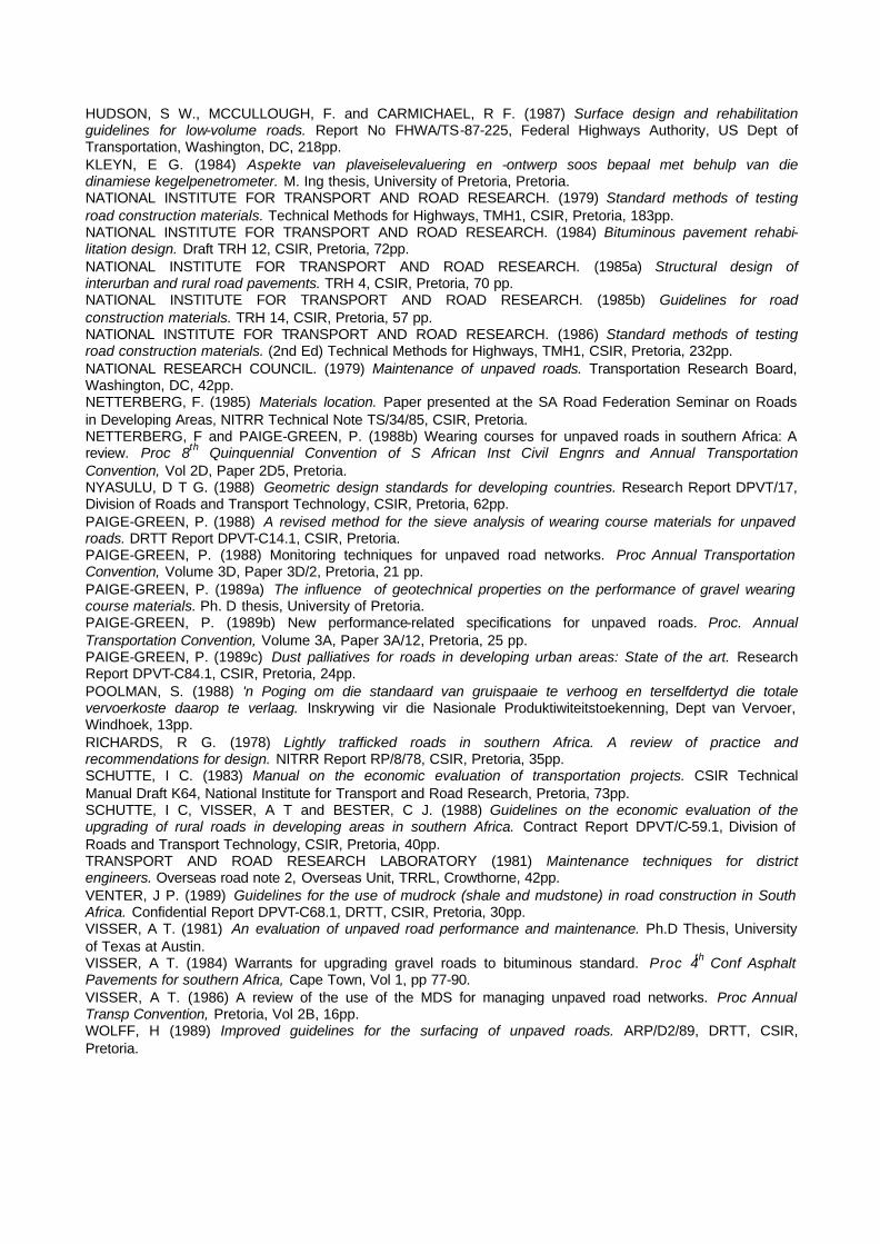
HUDSON, S W., MCCULLOUGH, F. and CARMICHAEL, R F. (1987) Surface design and rehabilitation guidelines for low-volume roads. Report No FHWA/TS-87-225, Federal Highways Authority, US Dept of Transportation, Washington, DC, 218pp. KLEYN, E G. (1984) Aspekte van plaveiselevaluering en -ontwerp soos bepaal met behulp van die dinamiese kegelpenetrometer. M. Ing thesis, University of Pretoria, Pretoria. NATIONAL INSTITUTE FOR TRANSPORT AND ROAD RESEARCH. (1979) Standard methods of testing road construction materials. Technical Methods for Highways, TMH1, CSIR, Pretoria, 183pp. NATIONAL INSTITUTE FOR TRANSPORT AND ROAD RESEARCH. (1984) Bituminous pavement rehabi-litation design. Draft TRH 12, CSIR, Pretoria, 72pp. NATIONAL INSTITUTE FOR TRANSPORT AND ROAD RESEARCH. (1985a) Structural design of interurban and rural road pavements. TRH 4, CSIR, Pretoria, 70 pp. NATIONAL INSTITUTE FOR TRANSPORT AND ROAD RESEARCH. (1985b) Guidelines for road construction materials. TRH 14, CSIR, Pretoria, 57 pp. NATIONAL INSTITUTE FOR TRANSPORT AND ROAD RESEARCH. (1986) Standard methods of testing road construction materials. (2nd Ed) Technical Methods for Highways, TMH1, CSIR, Pretoria, 232pp. NATIONAL RESEARCH COUNCIL. (1979) Maintenance of unpaved roads. Transportation Research Board, Washington, DC, 42pp. NETTERBERG, F. (1985) Materials location. Paper presented at the SA Road Federation Seminar on Roads in Developing Areas, NITRR Technical Note TS/34/85, CSIR, Pretoria. NETTERBERG, F and PAIGE-GREEN, P. (1988b) Wearing courses for unpaved roads in southern Africa: A review. Proc 8th Quinquennial Convention of S African Inst Civil Engnrs and Annual Transportation Convention, Vol 2D, Paper 2D5, Pretoria. NYASULU, D T G. (1988) Geometric design standards for developing countries. Research Report DPVT/17, Division of Roads and Transport Technology, CSIR, Pretoria, 62pp. PAIGE-GREEN, P. (1988) A revised method for the sieve analysis of wearing course materials for unpaved roads. DRTT Report DPVT-C14.1, CSIR, Pretoria. PAIGE-GREEN, P. (1988) Monitoring techniques for unpaved road networks. Proc Annual Transportation Convention, Volume 3D, Paper 3D/2, Pretoria, 21 pp. PAIGE-GREEN, P. (1989a) The influence of geotechnical properties on the performance of gravel wearing course materials. Ph. D thesis, University of Pretoria. PAIGE-GREEN, P. (1989b) New performance-related specifications for unpaved roads. Proc. Annual Transportation Convention, Volume 3A, Paper 3A/12, Pretoria, 25 pp. PAIGE-GREEN, P. (1989c) Dust palliatives for roads in developing urban areas: State of the art. Research Report DPVT-C84.1, CSIR, Pretoria, 24pp. POOLMAN, S. (1988) 'n Poging om die standaard van gruispaaie te verhoog en terselfdertyd die totale vervoerkoste daarop te verlaag. Inskrywing vir die Nasionale Produktiwiteitstoekenning, Dept van Vervoer, Windhoek, 13pp. RICHARDS, R G. (1978) Lightly trafficked roads in southern Africa. A review of practice and recommendations for design. NITRR Report RP/8/78, CSIR, Pretoria, 35pp. SCHUTTE, I C. (1983) Manual on the economic evaluation of transportation projects. CSIR Technical Manual Draft K64, National Institute for Transport and Road Research, Pretoria, 73pp. SCHUTTE, I C, VISSER, A T and BESTER, C J. (1988) Guidelines on the economic evaluation of the upgrading of rural roads in developing areas in southern Africa. Contract Report DPVT/C-59.1, Division of Roads and Transport Technology, CSIR, Pretoria, 40pp. TRANSPORT AND ROAD RESEARCH LABORATORY (1981) Maintenance techniques for district engineers. Overseas road note 2, Overseas Unit, TRRL, Crowthorne, 42pp. VENTER, J P. (1989) Guidelines for the use of mudrock (shale and mudstone) in road construction in South Africa. Confidential Report DPVT-C68.1, DRTT, CSIR, Pretoria, 30pp. VISSER, A T. (1981) An evaluation of unpaved road performance and maintenance. Ph.D Thesis, University of Texas at Austin. VISSER, A T. (1984) Warrants for upgrading gravel roads to bituminous standard. Proc 4th Conf Asphalt Pavements for southern Africa, Cape Town, Vol 1, pp 77-90. VISSER, A T. (1986) A review of the use of the MDS for managing unpaved road networks. Proc Annual Transp Convention, Pretoria, Vol 2B, 16pp. WOLFF, H (1989) Improved guidelines for the surfacing of unpaved roads. ARP/D2/89, DRTT, CSIR, Pretoria.

APPENDIX A : Recommended test method for the grading analysis of unpaved road wearing course materials The test is a modified version of the procedure of Method B4 as specified in TMH1. TMH1 Methods A1(a) or A1(b) can also be used provided the results are calculated as a percentage of the component passing the 37,5 mm sieve.
1 SCOPE This method describes the sieve analysis of a dried wearing course gravel sample, after it has been washed through a 0,075 mm sieve, and makes allowance for the oversize material. The oversize material is determined from a bulk sample (usually the sample as collected in the field) whilst the test sample for the sieve analysis is quartered from the bulk sample.
2 APPARATUS
2.1 A suitable riffler.
2.2 A 37,5 mm sieve, recommended diameter 450 mm.
2.3 The following sieves, 200 mm in diameter, complying with the requirements of SABS 197 (sieves larger than 4,75 mm must be of perforated plate and sieves 4,76 mm and smaller of woven wire mesh): 26,5 mm, 19,0 mm, 13,2 mm, 6,7 mm, 4,75 mm, 2,0 mm, 0,425 mm and 0,075 mm together with a bottom pan and lid.
2.4 A mechanical sieve shaker (optional).
2.5 A balance with a pan to weigh up to 25 kg, accurate to 5 g.
2.6 A balance with a pan to weigh up to 5 kg, accurate to 1 g.
2.7 A suitable basin about 450 mm in diameter.
2.8 A pan about 300 mm square.
2.9 Flat pans about 200 mm in diameter and 30 cm deep.
2.10 A drying oven, thermostatically controlled and capable of maintaining a temperature of 105 to 110ºC.
2.11 The following brushes for cleaning the sieves: a brass or wire brush measuring approximately 50 mm x 25 mm with bristles not more than 25 mm long, and hard-bristle brushes measuring approximately 50 mm x 25 mm.
2.12 A 150 mm nominal diameter iron mortar and pestle and a rubber-tipped pestle.
3 METHOD
3.1 Size of bulk sample The approximate mass of the bulk and test samples is given in Table 1. These samples may only be obtained by quartering of the field sample and must by no means be weighed out exactly.
Appendix A Table 1: Approximate mass of bulk and test samples Maximum particle
size (mm) Approximate mass
of sample (kg) >75 >20
<75 but > 37,5 10 37,5 2 26,5 1,5 19,0 1,25
<19,0 0,75
3.2 Drying Place the bulk sample in a suitable basin(s) and dry in an oven at a temperature not exceeding 110ºC to constant mass. Weigh the bulk sample.
3.3 Oversize material The dried bulk sample is poured into the 450 mm diameter 37,5 mm sieve, which is placed in a 500 mm basin. Any large soil clods or aggregations retained on the sieve should be disintegrated in the mortar by applying pressure to the pestle or by tamping very lightly. As much of the fine material as possible should be brushed off the large particles with one of the hard-bristle brushes, and this

together with the disintegrated material is added to the portion passing the sieve, which is then subdivided in the riffler. The weight of the aggregate retained on the 37,5 mm sieve is recorded.
3.4 Quartering The portion of the sample passing the 37,5 mm sieve is poured into one or more of the riffler pans. The material is then poured through the riffler by slowly tilting the pan so that the material flows in an even stream over its width. At the same time the pan is moved to and fro along the full length of the riffler to ensure an even flow of the material. The process is repeated with the contents of one of the pans under the riffler until a sample of the required size (2 kg) is obtained. The weight of the test sample is recorded.
3.5 Washing
Place the material in a suitable basin, cover with tap water and soak overnight or boil vigorously for one minute and allow to cool. Agitate thoroughly in the water to loosen any dust particles adhering to the aggregate and to break down any clay lumps that may exist. Decant the wash water over the 0,075 mm sieve protected by one or two coarser sieves. The wash water containing the -0,075 mm material is discarded or allowed to run away. Continue this washing procedure until the wash water is clear. Transfer the material retained on the 0,075 mm sieve and the protecting sieves to a square pan by inverting the sieves one by one and washing down with water. The water in the pan is poured off carefully and the material dried in an oven at a temperature not exceeding 105 to 110ºC to constant mass.
3.6 Sieving Nest the required or specified sieves in order of decreasing size of opening from the top to the bottom and pour the sample onto the top sieve. Agitate the sieves by hand or with a mechanical shaker and continue sieving for a sufficient period in such a manner that, after completion, not more than one per cent by mass of the residue on any individual sieve will pass that sieve during one minute of continuous hand sieving. After sieving, the material retained on each sieve, as well as the material which has passed the bottom sieve is weighed and the results recorded on Form X.
4 CALCULATIONS
4.1 Calculate the mass of the -0,075 mm material by subtracting the total mass of the material retained on the sieves from the mass of the original test sample (see 3.3).
4.2 Convert the mass of each fraction retained between two sieves to a percentage of the total dry mass of the test sample (see 3.3 i.e. only the fraction smaller than 37,5 mm).
4.3 Convert the percentages retained on the sieves to percentages passing the sieves.
4.4 Calculate the percentages to the nearest 0,1.
4.5 Calculate the “Oversize index” as the mass of sample retained on the 37,5 mm sieve as a percentage of the total mass of the original dried bulk sample.
Report the following results to the nearest whole number on a suitable form: (a) The percentage passing each sieve. (b) The “Oversize index”. The results may also be plotted on a suitable grading sheet.

5 NOTES
5.1 The washing procedure for samples containing a high percentage of -0,075 mm material may be facilitated by dry sieving the sample prior to washing.
5.2 Table 2 gives the maximum allowable mass of material retained on a specific sieve 200 mm in diameter. To prevent overloading of a sieve, the material should be divided and sieved in more than one operation.
Appendix A Table 2: Maximum allowable mass on sieves
Sieve size
(mm) Maximum allowable mass on sieve
(kg) 26,5 0,8 19,0 0,6 13,2 0,4 6,7 0,3 4,75 0,25 2,00 0,2
0,425 0,2 0,075 0,1

APPENDIX B : BASIC listing of model to predict annual gravel loss and regravelling frequency This listing can be used to predict the regravelling frequency (in years) and the annual gravel loss (in mm per year) for a given road link. The link should have reasonably consistent material and traffic characteristics over the length analysed. The input parameters are prompted and the following units are used in the calculation (recommended ranges in brackets): Thickness of wearing course: mm (50 – 200) Average daily traffic: average number of vehicles per day (10 – 350) Weinert N-value: Dimensionless value (1 –10) (Figure B1) Percentage passing 26,5 mm sieve: per cent (70 – 100) Plastic limit: per cent (13 – 32; 10 if non-plastic) NB. Not PI Percentage passing 0,075 mm: per cent (10 – 75) LISTING: 10 REM Gravel loss prediction 20 INPUT “Thickness of wearing course (mm)”; T 30 INPUT “Average daily traffic”; ADT 40 INPUT “Weinert N-value”; N 50 INPUT “Percentage passing 26 mm sieve”;P26 60 INPUT “Plastic limit”; PL 70 INPUT “Percentage passing 0,075 mm sieve”;P75 80 LET PP=PL*P75 90 LET WLOSS=(.048*P26)-(.367*N)-(.0014*PP) 100 LET TRLOSS=ADT*(.059+(.0027*N)-(6.000001E-04*P26)) 110 LET LOSS=3.65*(TRLOSS+WLOSS) 120 LET FREQ=T/LOSS 130 PRINT “REGRAVELLING FREQUENCY (years)=”; FREQ 140 PRINT “ANNUAL GRAVEL LOSS (mm)=”; LOSS 150 GOTO 20 160 END

APPENDIX C : BASIC listing of model to predict change in roughness with time and blading frequency The listing provided predicts the roughness after blading (in Quartercar Index units (QI counts/km)) and the blading frequency (in days) required to avoid the roughness deteriorating to a value in excess of the selected maximum roughness (i.e. the roughness before blading). It may not always be possible to retain these limits for certain materials outside the recommended specifications, especially those materials with excessive oversize material. The following input units and recommended ranges should be used: Plastic limit: per cent (13 – 32: 10 if non-plastic) NB. Not PI Percentage passing 0,075 mm sieve: per cent (10 – 75) Season: A value of 1 should be used for the dry season and 0 for the wet season Percentage passing 26,5 mm sieve: per cent (87 – 100) Weinert N-value: Dimensionless value (1 – 10) (Figure B1) Average daily traffic: average number of vehicles per day (10 – 350) Grading modulus: Dimensionless value (0,3 – 2,5) Roughness before blading: Selected maximum acceptable roughness in QI counts/km (60 – 200) Dust ratio: Dimensionless ratio of percentage passing 0,075 mm and 0,425 mm sieves (0,24 – 0,92) Laboratory determined maximum size: mm (6,7 – 58) LISTING: 10 REM Roughness and blading frequency 20 INPUT “Plastic limit”; PL 30 INPUT “Percentage passing 0,075 mm sieve”; P75 40 LET PP=PL*P75 50 INPUT “Season”; S1 60 INPUT “Percentage passing 26 mm sieve”; P26 70 INPUT “Weinert N-value”; N 80 INPUT “Average daily traffic”; ADT 90 INPUT “Grading modulus”; GM 100 INPUT “Roughness before blading or prescribed maximum roughness”; RBBL 110 INPUT “Dust ratio”; DR 120 INPUT “Laboratory determined maximum size”; LABMAX 130 LET RABL = EXP (1.07 + (.699*LOG(RBBL)) + (.0004*ADT) + (.13*DR) + (.0019*LABMAX)) 140 LET RBBL 1 = .975*RBBL 150 LET RBBL 2 = 1.025*RBBL 160 LET D = .3 170 LET CHANGE = -13.8188 + (.00022*PP) + (6.350731E-02*S1) + (.137047*P26) + (.000345*ADT*N) + (GM*(6.4194 - .0634*P26)) 180 LET PQI = EXP (LOG(RABL) + (D*CHANGE)) 190 IF PQI <RBBL1 THEN GOTO 200 ELSE IF PQI>RBBL2 THEN GOTO 220 ELSE GOTO 240 200 D = D - .01 210 GOTO 180 220 D = D - .01 230 GOTO 180 240 BF - D *100 250 PRINT “ROUGHNESS AFTER BLADING – “;RABL 260 PRINT “PREDICTED BLADING FREQUENCY (days)”;BF 270 PRINT “PREDICTED ROUGHNESS AFTER REQUIRED DAYS”;PQI 280 GOTO 20 290 END

APPENDIX D : Check-list of maintenance management input requirements Link identification – including region, district, road number, kilometre points, length, required level of serviceability. Geometry – topography, curvature, grade, altitude, road width, road reserve. Traffic and climate – number of vehicles, percentage heavy, estimated growth rate, Weinert N value, dry and wet season identification. Material characteristics – percentage retained on 37,5 mm and passing 37,5, 26,5, 4,75, 2,0, 0,425 and 0,075 mm sieves, liquid limit, plastic limit, bar linear shrinkage, soaked and OMC CBR, laboratory determined maximum size, gravel type, regravelling date, gravel thickness. Performance – dustiness, potholes, corrugations, stoniness, rutting, cracking, erosion, slipperiness, impassability, ravelling, loose material.