Trebuchet Design - University of Waterloofatslab.uwaterloo.ca/data/ME380_Project_manual_F06.pdf ·...
75
ME380 Project Manual Mechanical Engineering Design Workshop Trebuchet Design Instructor: Hamid Jahed Department of Mechanical Engineering, University of Waterloo Fall 2006
Transcript of Trebuchet Design - University of Waterloofatslab.uwaterloo.ca/data/ME380_Project_manual_F06.pdf ·...

ME380 Project Manual
Mechanical Engineering Design Workshop
Trebuchet Design
Instructor: Hamid Jahed
Department of Mechanical Engineering,
University of Waterloo Fall 2006

ME380
Project Manual
Mechanical Engineering Design Workshop
Trebuchet Design
Copyright © 2006 by Hamid Jahed and Arash Tajik
Department of Mechanical Engineering
University of Waterloo
200 University Ave West
Waterloo, ON N2L 3G1

Table of Contents
1. Introduction............................................................................................................... 1
1.1. History of the Trebuchet ..................................................................................... 1
2. Project Description ................................................................................................... 4
2.1. Objectives ........................................................................................................... 4
2.2. Problem Statement .............................................................................................. 4
2.3. Rules and Regulations......................................................................................... 4
2.4. Trebuchet Competition ....................................................................................... 6
2.5. Reports Structure ................................................................................................ 8
2.6. Safety .................................................................................................................. 9
2.7. Marking Scheme ............................................................................................... 10
3. Trebuchet Dynamics - Theory ............................................................................... 11
3.1. Lagrangian Mechanics - A Short Introduction ................................................. 11
3.1.1. Double Pendulum Example ...................................................................... 14
3.2. Trebuchet Formulation...................................................................................... 16
4. Trebuchet Simulation in MSC.ADAMS/View ..................................................... 20
4.1. Introduction....................................................................................................... 20
4.2. Problem Description ......................................................................................... 23
4.3. Building the Model ........................................................................................... 24
4.4. Testing the Model ............................................................................................. 39
4.5. Improving the Model (Optimization)................................................................ 57
Appendix A. Counterweight Specifications ............................................................ 67
Appendix B. Launch Platform Specifications......................................................... 68
Appendix C. Report Title Page ................................................................................ 69
5. References ................................................................................................................ 72
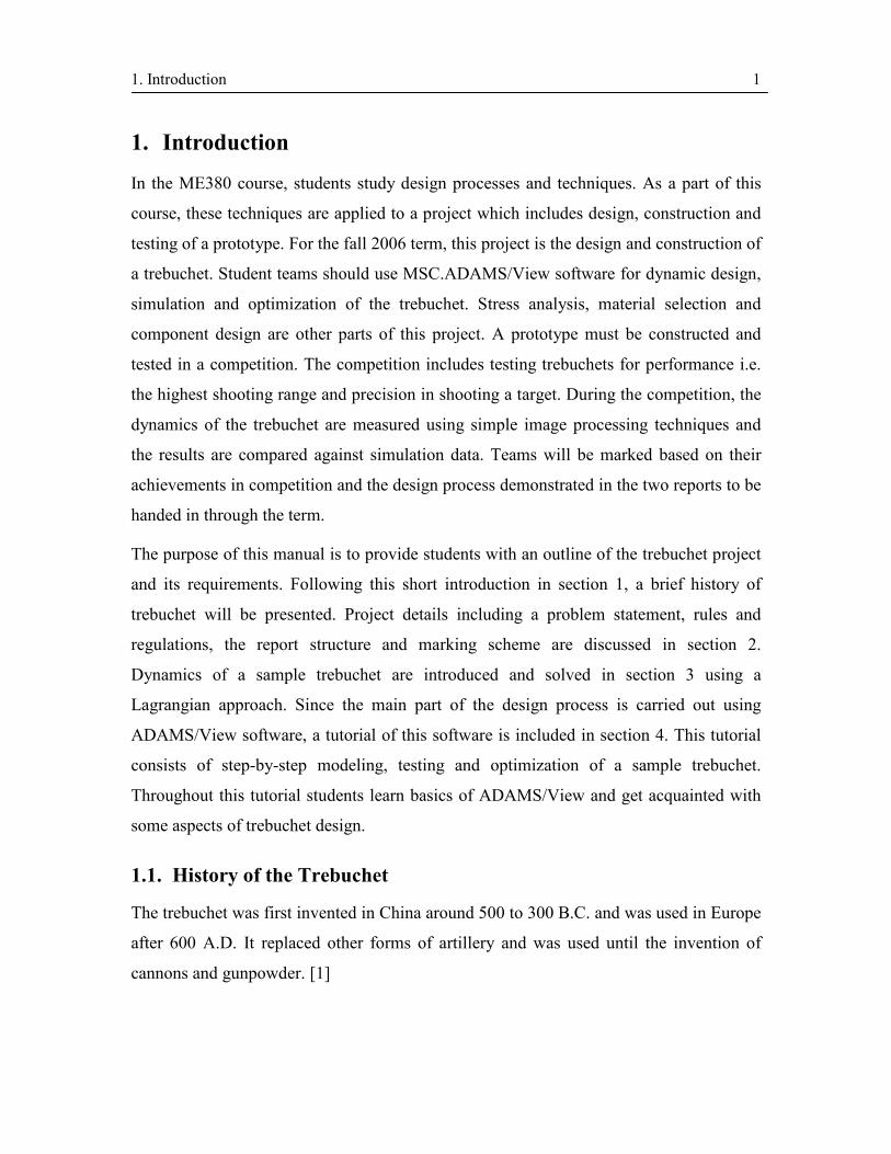
1. Introduction 1
1. Introduction
In the ME380 course, students study design processes and techniques. As a part of this
course, these techniques are applied to a project which includes design, construction and
testing of a prototype. For the fall 2006 term, this project is the design and construction of
a trebuchet. Student teams should use MSC.ADAMS/View software for dynamic design,
simulation and optimization of the trebuchet. Stress analysis, material selection and
component design are other parts of this project. A prototype must be constructed and
tested in a competition. The competition includes testing trebuchets for performance i.e.
the highest shooting range and precision in shooting a target. During the competition, the
dynamics of the trebuchet are measured using simple image processing techniques and
the results are compared against simulation data. Teams will be marked based on their
achievements in competition and the design process demonstrated in the two reports to be
handed in through the term.
The purpose of this manual is to provide students with an outline of the trebuchet project
and its requirements. Following this short introduction in section 1, a brief history of
trebuchet will be presented. Project details including a problem statement, rules and
regulations, the report structure and marking scheme are discussed in section 2.
Dynamics of a sample trebuchet are introduced and solved in section 3 using a
Lagrangian approach. Since the main part of the design process is carried out using
ADAMS/View software, a tutorial of this software is included in section 4. This tutorial
consists of step-by-step modeling, testing and optimization of a sample trebuchet.
Throughout this tutorial students learn basics of ADAMS/View and get acquainted with
some aspects of trebuchet design.
1.1. History of the Trebuchet
The trebuchet was first invented in China around 500 to 300 B.C. and was used in Europe
after 600 A.D. It replaced other forms of artillery and was used until the invention of
cannons and gunpowder. [1]

1. Introduction 2
The trebuchet was a very powerful replacement for catapults. Unlike catapults that use
the energy of a twisted rope, a trebuchet relies on the energy provided by a falling
counterweight. The average catapult could launch 13 to 18 kilogram projectiles while
trebuchets are reported to have launched projectiles as heavy as a compact car (~500kg)
to an 80 meter distance using 30-tonne counterweight. They had been designed to throw
projectiles much more accurately than other medieval artillery and were used to attack a
specific target( e.g. a portion of a castle wall) unlike catapults, which were normally used
to instill fear rather than destroy a target. These machines have played a key role in
distribution of Black Plague, killing up to a third or two thirds of Europeans in the mid
14th century.
Figure 1- Trebuchet [2]
A common trebuchet is shown in Figure 1. It has a very simple structure and mechanism.
It consists of a lever having counterweight on one side and projectile on the other side.
Having triggered the mechanism, the overhanging counterweight falls down and transfers

1. Introduction 3
its potential energy to kinetic energy which is in turn transferred to the projectile by the
lever pivoted to a fulcrum.
Trebuchets were developed and optimized in their very first years by engineers – indeed
the word “engineering” is intimately related to them. “In Latin and the European
vernaculars, a common term for trebuchet was ‘engine’ (from ingenium, ‘an ingenious
contrivance’), and those who designed, made and used them were called ingeniators.” [1]
It took years for engineers to develop the early designs by trial and error to increase the
performance and precision of the trebuchet while decreasing its total weight.
Centuries later, potential engineers at the University of Waterloo will use modern tools to
design and optimize the medieval siege engine – THE TREBUCHET.

2. Project Description 4
2. Project Description
2.1. Objectives
This project is intended to provide students with a clear understanding of the design
process through a hands-on experience in design, construction and testing of an optimized
dynamic device, with emphasis on utilization of multidisciplinary knowledge learned so
far in the Mechanical Engineering program.
2.2. Problem Statement
Students are supposed to design and build a Trebuchet to launch a given projectile using a
given amount of energy, i.e. potential energy of a counterweight resting high above the
ground. MSC.ADAMS/View will be used to simulate and optimize dynamics of the
trebuchet. Stress analysis is also required for structural design and mass optimization.
Projects will be marked based on performance, precision, agreement of simulation and
experimentation, the design process as demonstrated in the project report, creativity and
design quality. Performance of the machines will be judged based on maximum
utilization of the provided energy, i.e. maximum range thrown per unit mass of the
structure, and precision will be judged based on accuracy in shooting at a predefined
target. A camera will record the trebuchet in action and image processing techniques will
be used to track the projectile trajectory in order to compare the machine dynamics
simulations with reality.
2.3. Rules and Regulations
All teams must meet the following rules and regulations in order to be eligible to attend
the competition.
1. All teams must use a 4kg counterweight which will be provided in Student Machine
Shop two weeks before the competition. Geometry of the counterweight is shown in
Appendix A. Counterweight should be detachable for mass measurements.
2. Project Description 5
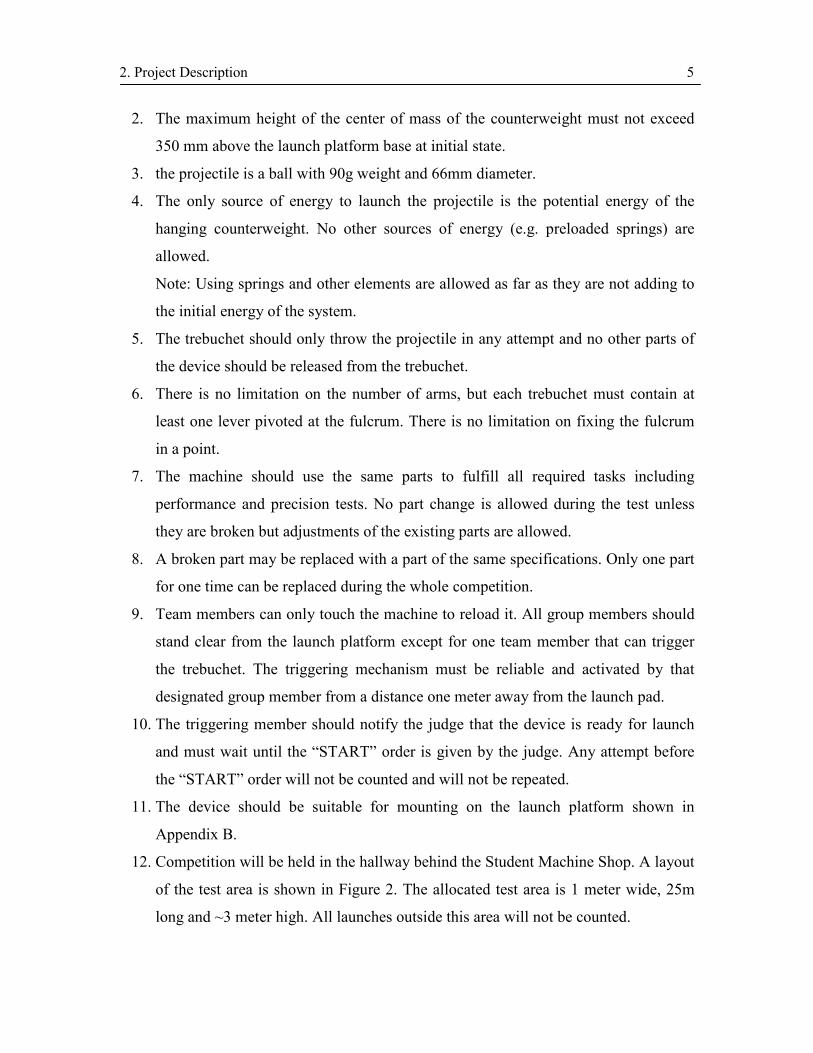
2. The maximum height of the center of mass of the counterweight must not exceed
350 mm above the launch platform base at initial state.
3. the projectile is a ball with 90g weight and 66mm diameter.
4. The only source of energy to launch the projectile is the potential energy of the
hanging counterweight. No other sources of energy (e.g. preloaded springs) are
allowed.
Note: Using springs and other elements are allowed as far as they are not adding to
the initial energy of the system.
5. The trebuchet should only throw the projectile in any attempt and no other parts of
the device should be released from the trebuchet.
6. There is no limitation on the number of arms, but each trebuchet must contain at
least one lever pivoted at the fulcrum. There is no limitation on fixing the fulcrum
in a point.
7. The machine should use the same parts to fulfill all required tasks including
performance and precision tests. No part change is allowed during the test unless
they are broken but adjustments of the existing parts are allowed.
8. A broken part may be replaced with a part of the same specifications. Only one part
for one time can be replaced during the whole competition.
9. Team members can only touch the machine to reload it. All group members should
stand clear from the launch platform except for one team member that can trigger
the trebuchet. The triggering mechanism must be reliable and activated by that
designated group member from a distance one meter away from the launch pad.
10. The triggering member should notify the judge that the device is ready for launch
and must wait until the “START” order is given by the judge. Any attempt before
the “START” order will not be counted and will not be repeated.
11. The device should be suitable for mounting on the launch platform shown in
Appendix B.
12. Competition will be held in the hallway behind the Student Machine Shop. A layout
of the test area is shown in Figure 2. The allocated test area is 1 meter wide, 25m
long and ~3 meter high. All launches outside this area will not be counted.

2. Project Description 6
Figure 2- Test area layout
13. Teams are free to choose any material.
14. Each team will be paid a total of $70 for material costs. Each team is required to
designate a member as the team leader who is the only team member that has
authority in purchasing from Engineering Machine Shop store using the account
number that will be provided at the beginning of the term. Group Leaders should
see Donna Kellendonk (E2-2328A) for up to $70 reimbursement.
15. All designs will be checked for safety and design regulations before the test.
Disqualified teams are not allowed to continue the test unless they fix the problem
in a timely manner. Disqualifications will affect the mark designated for design
quality.
16. With the counterweight removed, release of the trigger mechanism must not cause
the trebuchet to ‘launch’. This rule specifically prohibits the use of additional
counterweights or components designed to increase initial potential energy.
17. Violation of the intent of a rule will constitute violation of that rule. Specific
questions about the rules should be directed to instructor or TA’s.
2.4. Trebuchet Competition
The competition will start with a safety check of the trigger mechanisms and procedure.
Safety is the single most important requirement for entering the competition. Only minor
25 m
3m
1m
Hallway Walls
Shooting Area Launch Platform
2. Project Description 7
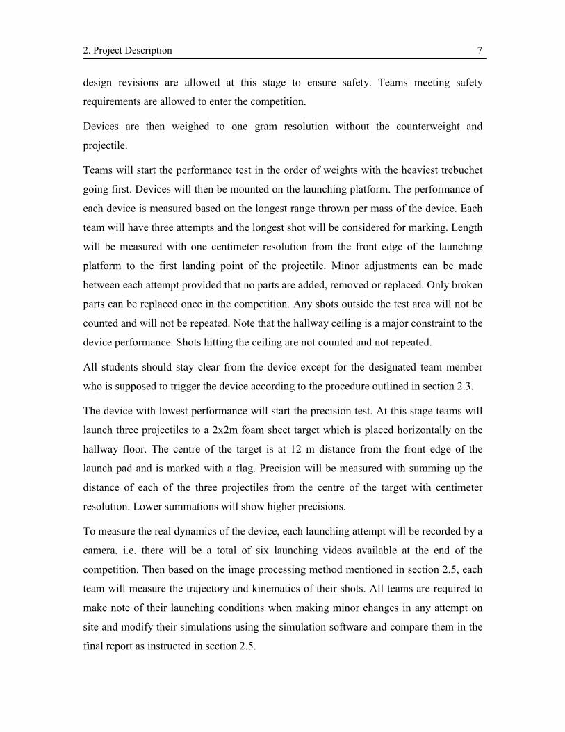
design revisions are allowed at this stage to ensure safety. Teams meeting safety
requirements are allowed to enter the competition.
Devices are then weighed to one gram resolution without the counterweight and
projectile.
Teams will start the performance test in the order of weights with the heaviest trebuchet
going first. Devices will then be mounted on the launching platform. The performance of
each device is measured based on the longest range thrown per mass of the device. Each
team will have three attempts and the longest shot will be considered for marking. Length
will be measured with one centimeter resolution from the front edge of the launching
platform to the first landing point of the projectile. Minor adjustments can be made
between each attempt provided that no parts are added, removed or replaced. Only broken
parts can be replaced once in the competition. Any shots outside the test area will not be
counted and will not be repeated. Note that the hallway ceiling is a major constraint to the
device performance. Shots hitting the ceiling are not counted and not repeated.
All students should stay clear from the device except for the designated team member
who is supposed to trigger the device according to the procedure outlined in section 2.3.
The device with lowest performance will start the precision test. At this stage teams will
launch three projectiles to a 2x2m foam sheet target which is placed horizontally on the
hallway floor. The centre of the target is at 12 m distance from the front edge of the
launch pad and is marked with a flag. Precision will be measured with summing up the
distance of each of the three projectiles from the centre of the target with centimeter
resolution. Lower summations will show higher precisions.
To measure the real dynamics of the device, each launching attempt will be recorded by a
camera, i.e. there will be a total of six launching videos available at the end of the
competition. Then based on the image processing method mentioned in section 2.5, each
team will measure the trajectory and kinematics of their shots. All teams are required to
make note of their launching conditions when making minor changes in any attempt on
site and modify their simulations using the simulation software and compare them in the
final report as instructed in section 2.5.
2. Project Description 8
At the end of the competition devices will be displayed to general audience and are
marked for creativity and quality of design. The marking for this part will be done by a
judging team including course instructor, TAs, team leaders and two of the Mechanical
Engineering Department professors.
2.5. Reports Structure
Students must hand in two reports: an interim report and a final report.
The interim report must completely demonstrate your design process, including back of
the envelope calculations, dynamic simulations using ADAMS/View, stress analysis and
material selection, design optimizations and final drawings. At this stage your design
must be finalized and be ready to be built. Only minor modifications, unless approved by
instructor or TAs, can be made to the system after this stage.
There should be nine main components in your interim report:
1. Title Page
2. Table of Contents
3. Summary
- Briefly stating approach, findings and recommendations
4. Introduction
- Brief background and objective review,
- Organization of the report
5. Main Body
- Theory and technical background
- Design criteria and constraints identification and analysis
- Design options (must include free hand drawings)
- Decision matrix and method of evaluation
- Procedures and analysis techniques (ADAMS/View Simulations)

2. Project Description 9
- Analysis and calculations results (Optimization)
- Detailed design
- Discussions
6. Conclusion
7. Recommendations
8. References
9. Appendices
- Additional calculations or formulations, if necessary
- Detailed drawings
Note that drawings are mandatory and must be prepared in detail using any of the
available CAD software. Upon submitting interim reports, teams will be notified of any
design problems that may be against rules and regulations or safety considerations.
The final report must include a summary of all key features of the design process
discussed in interim report in addition to modifications, test results and discussions. This
report must contain all nine components of interim report in addition to test results and
comparison of the physical tests to simulations to be added in the main body of the report.
2.6. Safety
Safety is a major concern through out the project. All teams must design and build
devices safe enough to not endanger other students, judges and spectators. Devices with
safety problems will not be allowed to compete until the safety concerns have been
addressed. Teams must operate their devices in a safe manner. Please always wear safety
glasses when launching or reloading the device.

2. Project Description 10
2.7. Marking Scheme
Interim Report: Preliminary Design: 15
Analysis and Design Optimization: 10
Detailed Design: 15
Test Results: Competition Attendance: 10
Performance: 10
Precision: 10
Creativity and Design Quality: 10
Final Report: Simulation/Experimentation Comparison: 10
Discussion: 10
Total Marks: 100
Team members will be asked for peer evaluation and based on their share in team work,
each team member will be marked. The share of each team member will appear on the
report cover page available in Appendix C of this manual.

3. Trebuchet Dynamics - Theory 11
3. Trebuchet Dynamics - Theory
As mentioned in section 2, the main part of the project is analysis and optimization of
trebuchet dynamics. A trebuchet, in its fully developed form, is a multi body system that
can hardly be solved using Newtonian mechanics. A simpler and more advanced
approach to solve these sorts of problems is Lagrangian mechanics. Further in this
section, a brief introduction to Lagrangian mechanics will be presented and different
trebuchet configurations will be modeled using this approach. It should be noted that
learning this section is optional and it is only included here to help you with a better
understanding of trebuchet dynamics and formulation.
3.1. Lagrangian Mechanics - A Short Introduction1
Newtonian mechanics are a set of rules that simplify a complex system to a simple free
body diagram and help in solving the kinematics and dynamics of the system. When it
comes to motion of a multi-body system with complicated degrees of freedom, using this
formalism needs extra patience and huge amount of computation time.
About two centuries after Sir Isaac Newton published these principals in Principia, his
approach to mechanics was reformulated to include more powerful methods that could
handle much more complicated systems with relative ease. One of these techniques was
developed by the great Italian-French mathematician, Joseph Louis Lagrange and was
published in his Mechanique Analytique. Contrary to Newton’s fully physical approach to
mechanics, Lagrange used pure mathematics to analyze the motion by defining
Lagrangian and using the Principle of Least Action.
Lagrangian: Define the Lagrangian to be a function of the position, x and the velocities,
x& of all the particles, given by
)()(),( xVxTxxL −= && (1)
where ∑= 2)(21 xmT & is the kinetic energy, and )(xV is the potential energy of particles.
1 A more detailed discussion of Lagrangian Mechanics can be found in [3]-[6] .
3. Trebuchet Dynamics - Theory 12
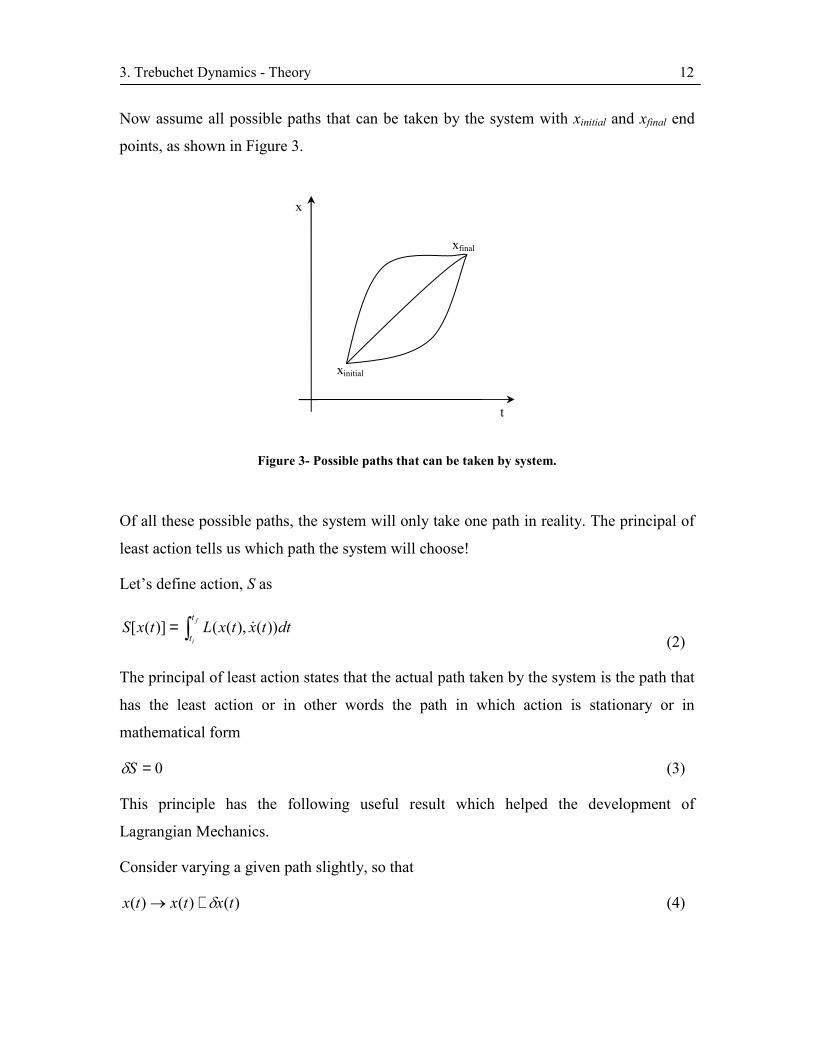
Now assume all possible paths that can be taken by the system with xinitial and xfinal end
points, as shown in Figure 3.
Figure 3- Possible paths that can be taken by system.
Of all these possible paths, the system will only take one path in reality. The principal of
least action tells us which path the system will choose!
Let’s define action, S as
∫= f
i
t
tdttxtxLtxS ))(),(()]([ &
(2)
The principal of least action states that the actual path taken by the system is the path that
has the least action or in other words the path in which action is stationary or in
mathematical form
0=Sδ (3)
This principle has the following useful result which helped the development of
Lagrangian Mechanics.
Consider varying a given path slightly, so that
)()()( txtxtx δ+→ (4)
x
xinitial
t
xfinal
3. Trebuchet Dynamics - Theory 13
where we fix the end points of the path by demanding 0)()( == fi txtx δδ . Then the
change in the action is
dtxxLx
xL
dtL
dtLS
f
i
f
i
f
i
t
t
t
t
t
t
∫
∫
∫
∂∂+
∂∂=
=
=
&&δδ
δ
δδ
(5)
At this point we integrate the second term by parts to get
f
i
f
i
t
t
t
tx
xLdtx
xL
dtd
xLS
∂∂+
∂∂
−∂∂= ∫ δδδ
&&(6)
But the final term vanishes since we assumed that end points are fixed
so 0)()( == fi txtx δδ . The requirement of the principle of least action i.e. 0=Sδ holds if
and only if
0=
∂∂
−∂∂
xL
dtd
xL
&(7)
This equation is known as the Lagrange Equation.
Substituting the Lagrangian definition of equation 1 into Lagrange Equation of equation
7,
( ) .0
.0
.0)()(
=−∂∂
=
∂∂
−∂∂
=
∂−∂
−∂−∂
mvdtd
xV
xT
dtd
xV
xVT
dtd
xVT
&
&
(8)
which is the equivalent of Newtonian formalism of motion, ( ) Vmvdtd
∇= . This means
we could also show that Lagrange Equation is the same as Newton’s.
3. Trebuchet Dynamics - Theory 14
The Lagrangian formulation has three main advantages over the classical Newton’s; First,
Lagrange’s equation holds in any coordinate system, while Newton’s are restricted to an
inertial frame. Second, it is easier to deal with constraints in Lagrangian formulation than
Newtonian. And third, as it was shown in the above equations, Lagrangian mechanics
works with energies rather than forces which puts relation in scalar form rather than
vector form and hence does not requiring vector calculus!
To put it in the nutshell, all you have to do in Lagrangian Mechanics is to calculate
kinetic and potential energies for all particles in your system, plug them into the Lagrange
Equation, and do some simple differentiation and integration.
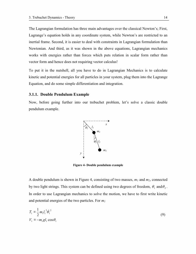
3.1.1. Double Pendulum Example
Now, before going further into our trebuchet problem, let’s solve a classic double
pendulum example.
Figure 4- Double pendulum example
A double pendulum is shown in Figure 4, consisting of two masses, m1 and m2, connected
by two light strings. This system can be defined using two degrees of freedom, 1θ and 2θ .
In order to use Lagrangian mechanics to solve the motion, we have to first write kinetic
and potential energies of the two particles. For m1
1111
21
2111
cos21
θ
θ
glmV
lmT
−=
= &(9)
θ1
θ2
l1
l2
m1
m2
x
y
3. Trebuchet Dynamics - Theory 15
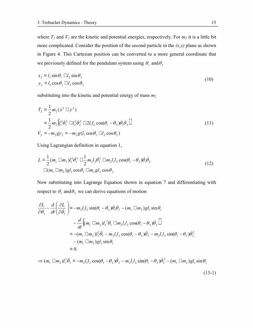
where T1 and V1 are the kinetic and potential energies, respectively. For m2 it is a little bit
more complicated. Consider the position of the second particle in the (x,y) plane as shown
in Figure 4. This Cartesian position can be converted to a more general coordinate that
we previously defined for the pendulum system using 1θ and 2θ
22112
22112
coscossinsin
θθθθ
llyllx
+=+=
(10)
substituting into the kinetic and potential energy of mass m2
( ))coscos(
)cos(221
)(21
22112222
21212122
22
21
212
2222
θθ
θθθθθθ
llgmgymV
llllm
yxmT
+−=−=
−++=
+=
&&&&
&&
(11)
Using Lagrangian definition in equation 1,
2221121
21212122222
21
2121
coscos)(
)cos(21)(
21
θθ
θθθθθθ
glmglmm
llmlmlmmL
+++
−+++= &&&&(12)
Now substituting into Lagrange Equation shown in equation 7 and differentiating with
respect to 1θ and 2θ we can derive equations of motion
( )
.0sin)(
)sin()cos()(
)cos()(
sin)()sin(
1121
22212122212121
2121
22121212
121
1121212121211
=+−
−−−−+−=
−++−
+−−−=
∂∂
−∂∂
θθθθθθθθ
θθθθ
θθθθθθθ
glmmllmllmlmm
llmlmmdtd
glmmllmLdtdL
&&&&&
&&
&&&
112122212122212121
2121 sin)()sin()cos()( θθθθθθθθ glmmllmllmlmm +−−−−−=+⇒ &&&&&
(13-1)
3. Trebuchet Dynamics - Theory 16
( )
.0)sin(
)sin()cos(
)cos(
)sin()sin(
222
2121212121212222
121212222
222212121212
=−
−+−−−=
−+−
−−=
∂∂
−∂∂
θθθθθθθθ
θθθθ
θθθθθθθ
glmllmllmlm
llmlmdtd
glmllmLdtdL
&&&&&
&&
&&&
)sin()sin()cos( 2222
121212121212222 θθθθθθθθ glmllmllmlm −−+−−=⇒ &&&&& (13-2)
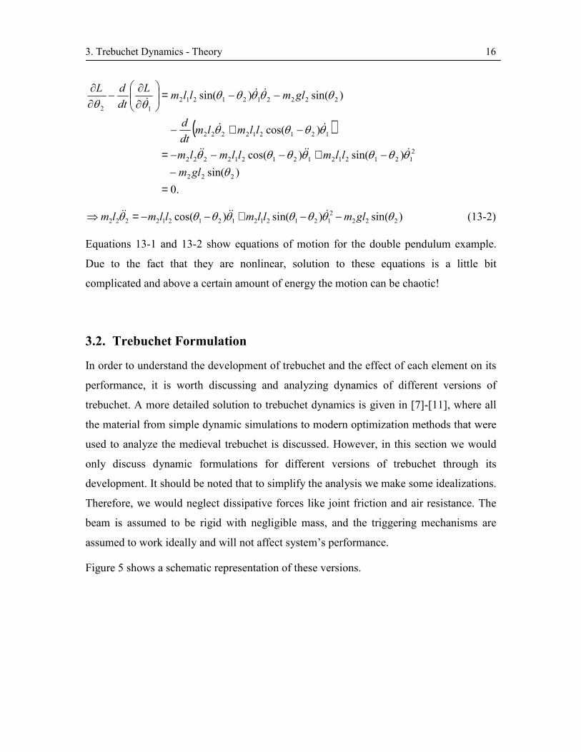
Equations 13-1 and 13-2 show equations of motion for the double pendulum example.
Due to the fact that they are nonlinear, solution to these equations is a little bit
complicated and above a certain amount of energy the motion can be chaotic!
3.2. Trebuchet Formulation
In order to understand the development of trebuchet and the effect of each element on its
performance, it is worth discussing and analyzing dynamics of different versions of
trebuchet. A more detailed solution to trebuchet dynamics is given in [7]-[11], where all
the material from simple dynamic simulations to modern optimization methods that were
used to analyze the medieval trebuchet is discussed. However, in this section we would
only discuss dynamic formulations for different versions of trebuchet through its
development. It should be noted that to simplify the analysis we make some idealizations.
Therefore, we would neglect dissipative forces like joint friction and air resistance. The
beam is assumed to be rigid with negligible mass, and the triggering mechanisms are
assumed to work ideally and will not affect system’s performance.
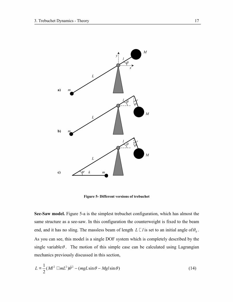
Figure 5 shows a schematic representation of these versions.
3. Trebuchet Dynamics - Theory 17
Figure 5- Different versions of trebuchet
See-Saw model. Figure 5-a is the simplest trebuchet configuration, which has almost the
same structure as a see-saw. In this configuration the counterweight is fixed to the beam
end, and it has no sling. The massless beam of length lL + is set to an initial angle of 0θ .
As you can see, this model is a single DOF system which is completely described by the
single variableθ . The motion of this simple case can be calculated using Lagrangian
mechanics previously discussed in this section,
)sinsin()(21 222 θθθ MglmgLmLMlL −−+= & (14)
m
L
l
M
θ
y
x
m
L
l
M
rθ ϕ
m
L
l
M
rθ ϕ
kψ
a)
b)
c)

3. Trebuchet Dynamics - Theory 18
substituting into equation 7 an differentiating with respect to θ ,
0cos)()( 22 =−++ θθ gMlmLmLMl && (15)
Solving this equation with 0)0( θθ ==t initial condition gives the equation of motion for
simplest trebuchet configuration. As we will see later, this system is the only
configuration that can be solved analytically. All other configurations need to be solved
numerically.
Trebuchet with hinged counterweight. Figure 5-b shows the configuration with hinged
counterweight. The counterweight is hinged using a link of length r. As you can see, this
model is a 2DOF system described by θ andϕ . Using the analogy to double pendulum
example discussed earlier, the Lagrangian for this configuration is
[ ])cossin(sin))sin(2(21
21 222222 ϕθθϕθϕϕθθθ rlMgmgLrlrlMmLL −−−
+−++= &&&&&
(16)
substituting into equation 7 and differentiating with respect to θ andϕ ,
ϕθϕθθϕθϕ
θθϕϕθϕϕθ
sin)cos()sin(
cos)()cos()sin()(22
222
MgrMlrMlrMrgmLMlMlrMlrMlmL
+−+−−=
−+−−−−=+&&&&&
&&&&&(17)
The equation of motion of this configuration is coupled and nonlinear and can be solved
numerically.
Trebuchet with sling and hinged counterweight. The most improved medieval
trebuchet is the one with both sling and hinged counterweight. (Figure 5-c) In this case
the projectile is connected to the lever using a mass less sling of length k. This
configuration is a 3DOF system that is described usingθ , ϕ andψ . The Lagrangian for
this equation is
[ ])cossin()sinsin(
))cos(2(21))sin(2(
21 22222222
ϕθψθ
ψψθψθθϕθϕϕθθ
rlMgkLmg
kLkLmrlrlML
−−+−−
+−+++−+= &&&&&&&&
(18)
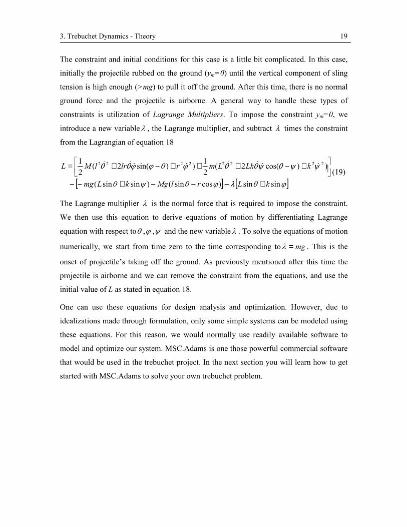
3. Trebuchet Dynamics - Theory 19
The constraint and initial conditions for this case is a little bit complicated. In this case,
initially the projectile rubbed on the ground (ym=0) until the vertical component of sling
tension is high enough (>mg) to pull it off the ground. After this time, there is no normal
ground force and the projectile is airborne. A general way to handle these types of
constraints is utilization of Lagrange Multipliers. To impose the constraint ym=0, we
introduce a new variableλ , the Lagrange multiplier, and subtract λ times the constraint
from the Lagrangian of equation 18
[ ] [ ]ϕθλϕθψθ
ψψθψθθϕθϕϕθθ
sinsin)cossin()sinsin(
))cos(2(21))sin(2(
21 22222222
kLrlMgkLmg
kLkLmrlrlML
+−−−+−−
+−+++−+= &&&&&&&&
(19)
The Lagrange multiplier λ is the normal force that is required to impose the constraint.
We then use this equation to derive equations of motion by differentiating Lagrange
equation with respect toθ ,ϕ ,ψ and the new variableλ . To solve the equations of motion
numerically, we start from time zero to the time corresponding to mg=λ . This is the
onset of projectile’s taking off the ground. As previously mentioned after this time the
projectile is airborne and we can remove the constraint from the equations, and use the
initial value of L as stated in equation 18.
One can use these equations for design analysis and optimization. However, due to
idealizations made through formulation, only some simple systems can be modeled using
these equations. For this reason, we would normally use readily available software to
model and optimize our system. MSC.Adams is one those powerful commercial software
that would be used in the trebuchet project. In the next section you will learn how to get
started with MSC.Adams to solve your own trebuchet problem.

4. Trebuchet Simulation in MSC.ADAMS/View 20
4. Trebuchet Simulation in MSC.ADAMS/View
4.1. Introduction
The MSC.ADAMS® suite of software is the product of MSC.Software Corporation and is
the world’s most widely used mechanical system simulation software. It enables users to
produce virtual prototypes, realistically simulating the full motion behavior of complex
mechanical systems and quickly analyze multiple design variations in search for an
optimal design. This reduces the number of costly physical prototypes, improves design
quality and dramatically reduces product development time. MSC.ADAMS simulation
solutions have been utilized in numerous organizations in product development. These
organizations include but not limited to a wide range of automotive and aerospace
industry leaders like GM, Ford motors, SAAB, John Deere, Volkswagen, NASA, Boeing
and Bombardier Inc. Many medium and small product developers and manufacturers are
also using MSC.ADAMS as one of their design tools.
The MSC.ADAMS is a family of products each developed for a specific purpose. The
main MSC.ADAMS products are: [12]
ADAMS/View: This software lets you build models of mechanical systems and simulate
the full motion behavior of the models and can be used to quickly analyze multiple design
variations in search for an optimal design.
ADAMS/Solver: This software is a powerful numerical analysis application that solves
the equations of motion for kinetic, static, quasi-static and dynamic simulations.
ADAMS/Post Processor: This software is a powerful post processing tool that lets you
view the results of simulation performed using other products.
ADAMS/Aircraft: ADAMS/Aircraft is a specialized environment for modeling landing
gear and aircraft during various test conditions. It enables you to create virtual prototypes
of aircraft and landing gear subsystems, and analyze the virtual prototypes; much like you
would analyze physical prototypes and test aircrafts.
4. Trebuchet Simulation in MSC.ADAMS/View 21
ADAMS/Car: ADAMS/Car is a specialized environment for modeling vehicles. It
allows you to create virtual prototypes of vehicle subsystems and analyze the virtual
prototypes much like you would analyze the physical prototypes.
ADAMS/Flex: ADAMS/Flex is an add-on module to the MSC.ADAMS suite of
software that lets you add flexible bodies to your models to achieve more realistic
simulation results.
ADAMS/Insight: This software is a powerful design of experiment software. It is a stand
alone product that also works with many other MSC.ADAMS products. It lets you design
sophisticated experiments for measuring the performance of a mechanical system. It also
provides a collection of statistical tools for analyzing the results of your experiments so
that you can better understand how to refine and improve your system.
ADAMS/Rail: This software is a specialized environment for railway virtual
prototyping. It creates and analyzes rolling stocks dynamics.
ADAMS/Vibration: ADAMS/Vibration is an MSC.ADAMS plug-in for performing
frequency domain analyses. Using this software, you can study forced vibrations in the
models.
ADAMS/RealTime, ADAMS/Ride, ADAMS/Chassis, ADAMS/Controls,
ADAMS/Driveline, ADAMS/Durability, ADAMS/Engine, ADAMS/Tire and
ADAMS/AutoFlex are other products in MSC.ADAMS suite.
All of these products are made available to the University of Waterloo through the PACE
Program (Partners for the Advancement of Collaborative Engineering Education) and is
available to students in all Engineering Computing Labs.
In MSC.ADAMS, like all other CAE software, there are four main steps in simulation of
a model. These are preprocessing (modeling), solution, post processing and optimization.
In the current project you will use ADAMS/View to model your trebuchet,
ADAMS/Solver to solve your model and ADAMS/Post Processor to see the results of
your simulation and finally thought parametric design you will be able to optimize your
design. Although you rarely change your working environment out of ADAMS/View but

4. Trebuchet Simulation in MSC.ADAMS/View 22
you should know that these products are used throughout the simulation and you
indirectly interact with them.
This section will help you getting started with MSC.ADAMS/View through step-by-step
building, simulation and refinement of a simple trebuchet problem. These design steps
are shown in Table 1. In the process, you will learn how to use ADAM/View to solve
your own problem, from concept to the final design.
This tutorial is designed in a self explanatory manner. It is assumed that you will follow
this tutorial in sequential order. Therefore, procedures are discussed in more detail in the
beginning and less as you proceed to final sections.
Table 1- Design process steps
Build
• Model device elements including moving parts, joints and
connections
• Verify the model
Test • Perform simulations
• Measure the required parameters
Improve
• Refine
o Parameterize the critical elements
• Iterate
o Study the effect of design parameters on design objective
o Find sensitivity of design objectives to parameters
• Optimize
o Optimize the design to achieve the best performance by the best combination of design parameters
Compare • Compare your real test data with simulation data
4. Trebuchet Simulation in MSC.ADAMS/View 23
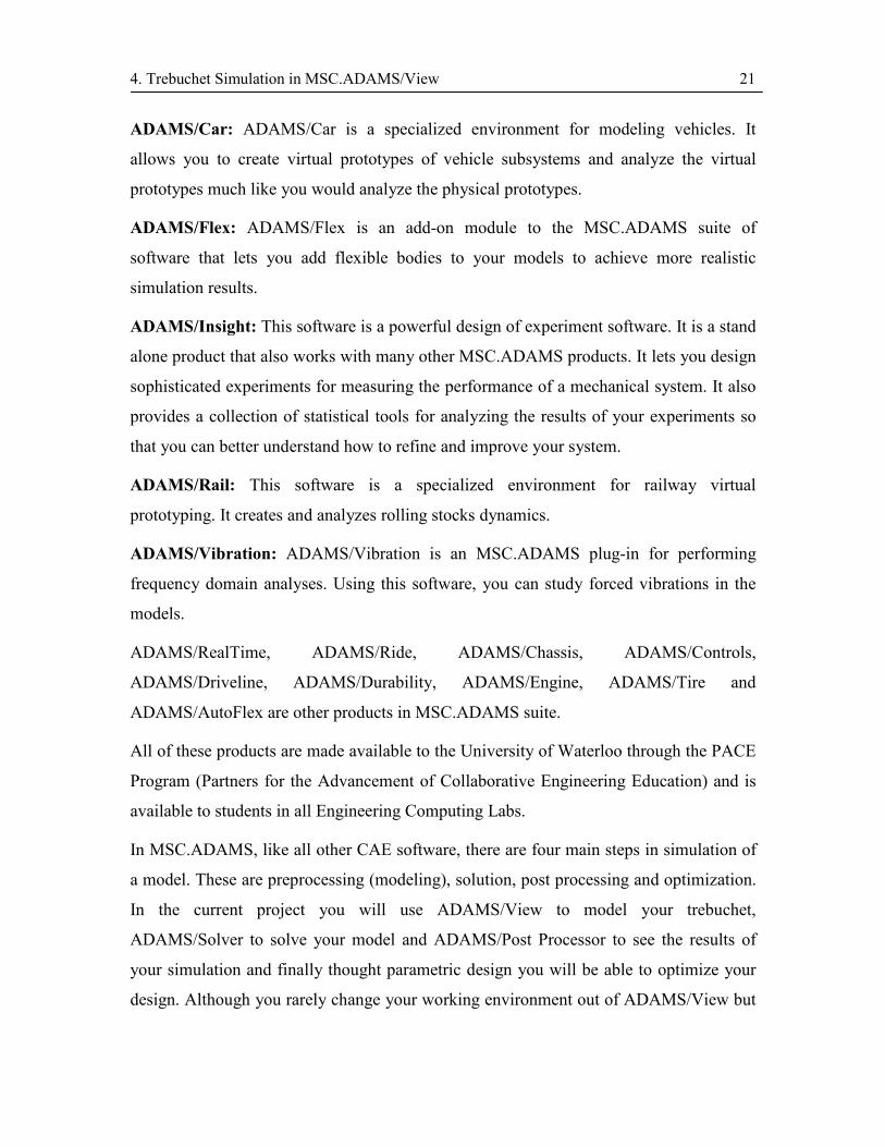
4.2. Problem Description
In this tutorial, you will build a simple trebuchet with sling and hinged counterweight, as
shown in Figure 6. This model must meet the following design requirements:
1. Counterweight mass of 4kg.
2. Projectile mass of 90g.
3. Maximum counterweight height of 35cm.
The effect of sling length, lever mass and releasing angle on range efficiency of the
trebuchet will be investigated.
Figure 6- Trebuchet model in ADAMS/View
4. Trebuchet Simulation in MSC.ADAMS/View 24
4.3. Building the Model
In this section you will learn how to start ADMAS/View and create a modeling database
containing a new model named Trebuchet. A modeling database contains all the work in
current session of ADAMS/View. It contains any models you create, their attributes,
simulation results, plots, customized menus and dialog boxes, and any preference you set.
ADAMS/View may be accessed from NEXUS.
To start ADAMS/View in the Windows environment of NEXUS:
� Select Start.
� Point to All Programs, point to Engineering, point to MSC.ADAMS 2005 r2, point to
AVIEW, and then select ADAMS – View.
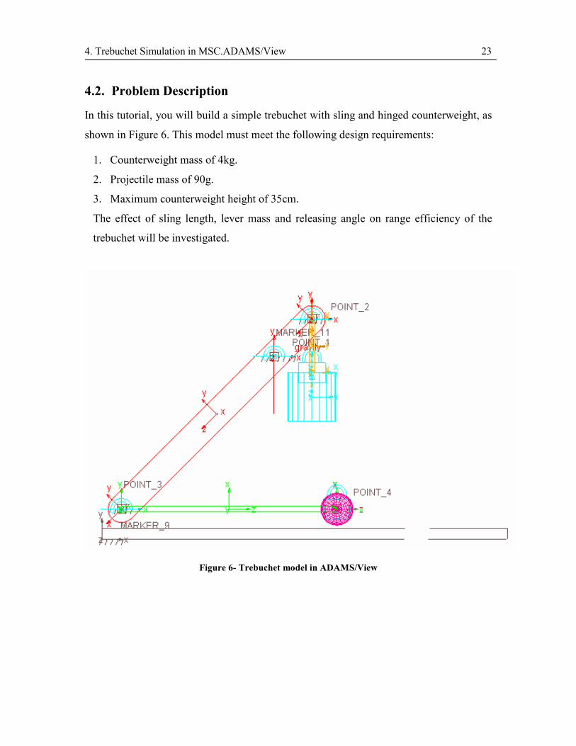
The Welcome dialog box appears.
Figure 7- MSC.ADAMS/View Welcome dialog box
To create a database from the Welcome dialog box:
� Select create a new model.
� From the Start in field select your working directory.
4. Trebuchet Simulation in MSC.ADAMS/View 25
� Set the Model name to Trebuchet.
� Set the Gravity to Earth Normal (-Global Y).
� Set Units to MMKS – mm,kg,N,s,deg from the drop down list.
Note: You can change Units and Gravity later in ADAMS/View environment.
� Select OK.
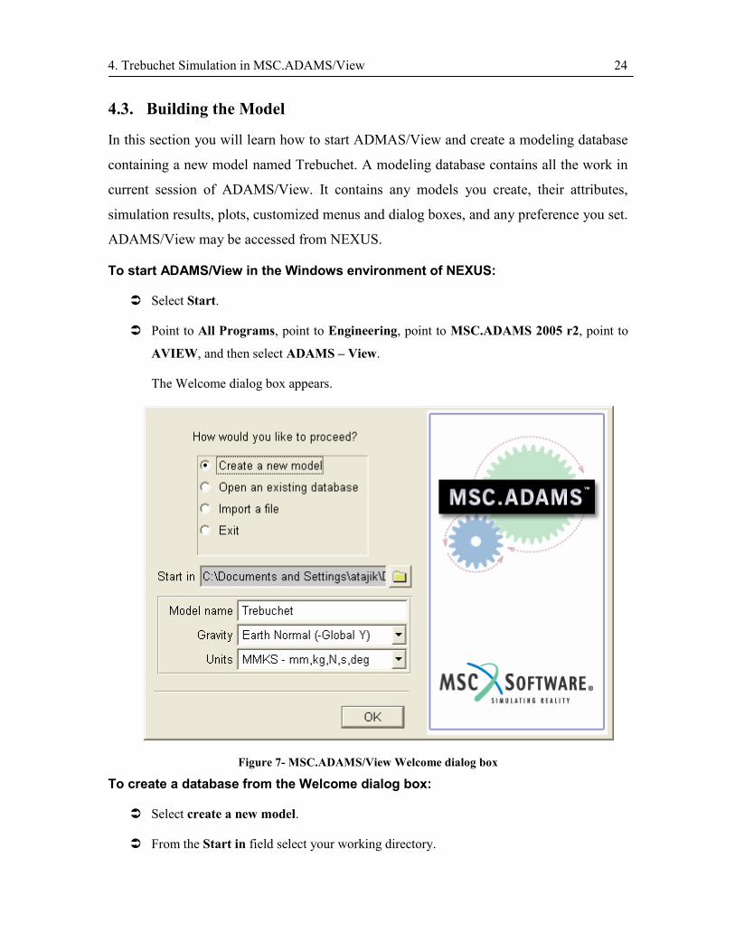
The ADAMS/View window will appear as shown in Figure 8.
Main ToolboxFigure 8- ADAMS/View window
Before continuing the tutorial, a short description of ADAMS/View will be presented to
make you more familiar with the software’s working environment.
When a model database is started for the first time, an ADAMS/View window opens
which consists of the Main Window and Main Toolbox. The Main Window is the
working space where you will build your model. You use Main Toolbox to access all of
the geometric construction elements (figure 8).
Main Window
Status Toolbar

4. Trebuchet Simulation in MSC.ADAMS/View 26
If Main Toolbox does not show up automatically, you can display it as follows:
To display the Main Toolbox:
� From the Main Window’s drop down menus, select View menu, select Toolbox and
Toolbars and check the Main Toolbox.
The Main Toolbox will appear.
Note: You can also activate this Toolbox, by selecting the Toolbox tool in the lower
right corner of the Main Window.
Some of the icons in the Main Toolbox have a small triangle in the lower right corner.
These icons show a stack of related tools. The default tool or the last selected tool appears
on top of the tool stack. To browse through the tool stack, right-click on the icon and
move the cursor over the tool you want to use, and click.
The bottom half of the Main Toolbox, called container, changes depending on the tool
that you select. Main Toolbox and its tool stacks are shown in Figure 9. When you hover
over any of the tools, a short description of the tool will appear on the Status Toolbar, at
the bottom of the Main Window. This description is very useful in selecting any tool, it
will guide you through the associated process.
Figure 9- Main Toolbox and its expanded tool stack
Triangle indicating a tool stack
Container
Tool stack

4. Trebuchet Simulation in MSC.ADAMS/View 27
When working in ADAMS/View you can use its detailed help through either of the
following procedures:
� Use the online help to read overviews, procedures, and see many examples. From the
Help menu, select ADAMS/View Help.
� Use the dialog box help to learn about entering values in a dialog box or using an
ADAMS/View tool. While working in a dialog box, press the F1 key.
We now return to the tutorial to build our trebuchet model.
Setting Up the Working Environment
In this section you set your unites, specify the grid size and display the coordinate
window.
To set up your work environment:
� From the Settings menu, select Units.
The Units Settings dialog box appears.
� Set the units of length to centimeter.
� Select OK.
Note 1: You can change the units at any time during the modeling process, even while
reading and writing model or results data files.
Note 2: If you do not enter a unit after the values you enter in fields, they will be treated
with the default unit. However, if you want to enter a value with a unit other than the
default unit, simply enter the unit after the value. For example instead of converting 10
inches to centimeters and entering 25.4 in the field, you can simply enter (10 inch).
� From the Settings menu, select Working Grid.
The Working Grid Settings dialog box appears.
� Set the grid size along X and Y to 70.
� Set the grid spacing for X and Y to 1.
� Select OK.

4. Trebuchet Simulation in MSC.ADAMS/View 28
� From the Settings menu, select Icons.
The Icon Settings dialog box appears.
� In the New Size text box, enter 4.0.
Note: The text box New Size is colored gray. Throughout
the ADAMS/View a grey test box means that value in the
box is optional and you do not necessarily need to enter any
value in the box.
� Near the bottom of the Icon Settings dialog box set Name
Visibility to On.
� Select OK.
To display the Coordinates window:
� From the View menu, select Coordinate Window.
The Coordinates window appears.
� Move your cursor around the screen and notice the coordinate location labels that appear
in the Coordinate window and next to the cursor.
Note: You can also display the Coordinate window by pressing F4.
Creating Design Points
In ADAMS/View you can change your design at any stage of design process. Using
design points in your design layout will help you make these changes easily. Simply
move the points and see the layout variations. Points are used to define locations in the
space on which you can position and parameterize other geometrical elements. Points are
the easiest method to design a parametric model. Later in this tutorial you will see the
advantages of the parametric design in refining and optimizing your model.
To create a design point:
� Right click on the Rigid Body tool stack to display the tool stack
containing the Point tool.
4. Trebuchet Simulation in MSC.ADAMS/View 29
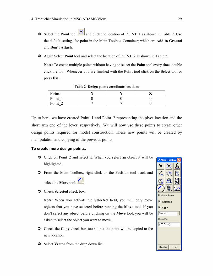
� Select the Point tool and click the location of POINT_1 as shown in Table 2. Use
the default settings for point in the Main Toolbox Container; which are Add to Ground
and Don’t Attach.
� Again Select Point tool and select the location of POINT_2 as shown in Table 2.
Note: To create multiple points without having to select the Point tool every time, double
click the tool. Whenever you are finished with the Point tool click on the Select tool or
press Esc.
Table 2- Design points coordinate locations
Point X Y Z Point_1 0 0 0 Point_2 7 7 0
Up to here, we have created Point_1 and Point_2 representing the pivot location and the
short arm end of the lever, respectively. We will now use these points to create other
design points required for model construction. These new points will be created by
manipulation and copying of the previous points.
To create more design points:
� Click on Point_2 and select it. When you select an object it will be
highlighted.
� From the Main Toolbox, right click on the Position tool stack and
select the Move tool.
� Check Selected check box.
Note: When you activate the Selected field, you will only move
objects that you have selected before running the Move tool. If you
don’t select any object before clicking on the Move tool, you will be
asked to select the object you want to move.
� Check the Copy check box too so that the point will be copied to the
new location.
� Select Vector from the drop down list.

4. Trebuchet Simulation in MSC.ADAMS/View 30
Note: With Vector option you can choose to move the object along a vector direction for
a definite distance, while with From to option you will move the object from a starting
point to a destination point.
� Set the Distance to 50cm.
� Hover over the Point_2. You will see some white colored vectors are highlighted as you
move over the Point_2 icon. These are the directions you can copy along. Move around
the icon until a hollow circle is highlighted at the center of the icon. Select that point.
� Select the center point of Point_1.
Point_2 is now copied to the new location, named Point along the direction defined by
POINT_1 and POINT_2.
To rename the POINT to POINT_3:
� Right click on the new point.
� Point to --Point: POINT and select Rename.
The Rename dialog box appears.
� Replace the POINT in New Name: with POINT_3.
� Select OK.
The point is renamed to POINT_3.
Note: As you create objects, ADAMS/View automatically assigns names to them. The
full name of an object is comprised of the concatenated names of its parent similar to a
directory structure in a file system. Because POINT_3 belongs to the part GROUND and
the GROUND belongs to the model Trebuchet, its full name is
.Trebuchet.ground.POINT_3.
Note: You can rename any object by right-clinking on that object and doing the same
process as stated above.

4. Trebuchet Simulation in MSC.ADAMS/View 31
� Select Point_3.
� Select Move tool again and set Distance to 40cm.
� Hove over Point_3 and select the vector highlighted along the x-axis. The label near the
cursor shows the name of this vector as POINT_3.X.
� Rename the new point to POINT_4.
Now you will have four points created in the main window as shown in Figure 10.
Figure 10- Created points in the main window
Creating the Links
We can create lever, swing rm, and the sling using Link tool.
To create the lever:
� From the Main Toolbox, right click on Point tool and select Link
tool .
� Click Point_2 and then Point_3 to create a link between the two
points.
� Rename the link part, Part:Part_2, to Lever.
4. Trebuchet Simulation in MSC.ADAMS/View 32
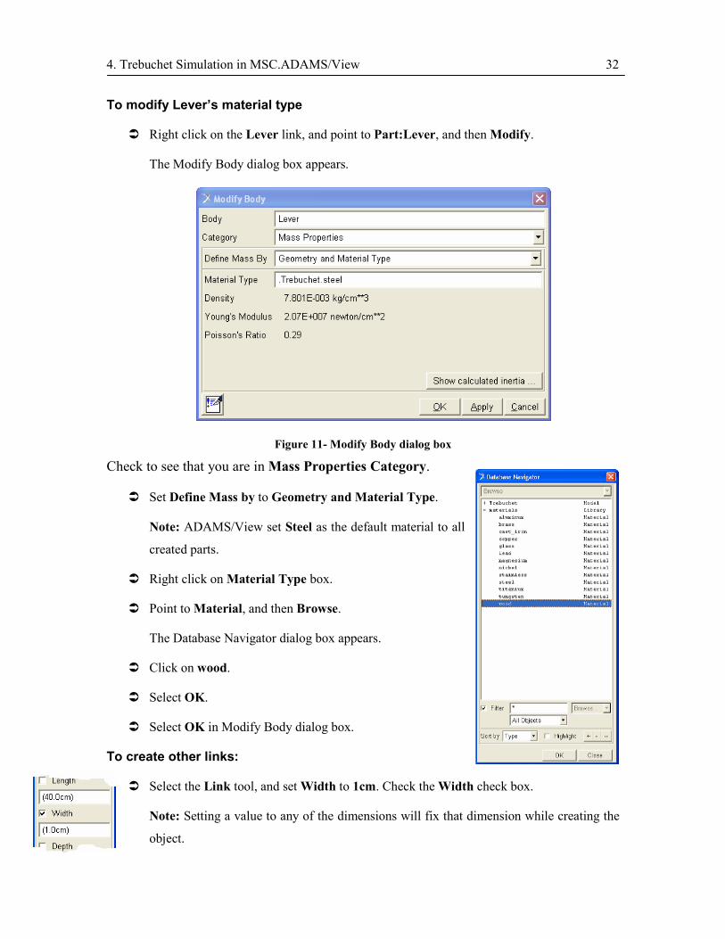
To modify Lever’s material type
� Right click on the Lever link, and point to Part:Lever, and then Modify.
The Modify Body dialog box appears.
Figure 11- Modify Body dialog box
Check to see that you are in Mass Properties Category.
� Set Define Mass by to Geometry and Material Type.
Note: ADAMS/View set Steel as the default material to all
created parts.
� Right click on Material Type box.
� Point to Material, and then Browse.
The Database Navigator dialog box appears.
� Click on wood.
� Select OK.
� Select OK in Modify Body dialog box.
To create other links:
� Select the Link tool, and set Width to 1cm. Check the Width check box.
Note: Setting a value to any of the dimensions will fix that dimension while creating the
object.
4. Trebuchet Simulation in MSC.ADAMS/View 33
� Click Point_3 and then Point_4.
� Rename the link part, Part: Part_3, to Sling.
� Right click the link part, point to Part: Sling, and then Modify.
� Under Define Mass by list, select Geometry and Density.
� Enter 5E-5 in Density box, which is almost the density of a rope.
� Select OK.
Note: In this tutorial it is assumed that the sling is always under tension and therefore
there would be no difference between a link which can bear both tension and
compression and a rope which is a tension only element. You find out how to model the
rope in ADAMS/View!
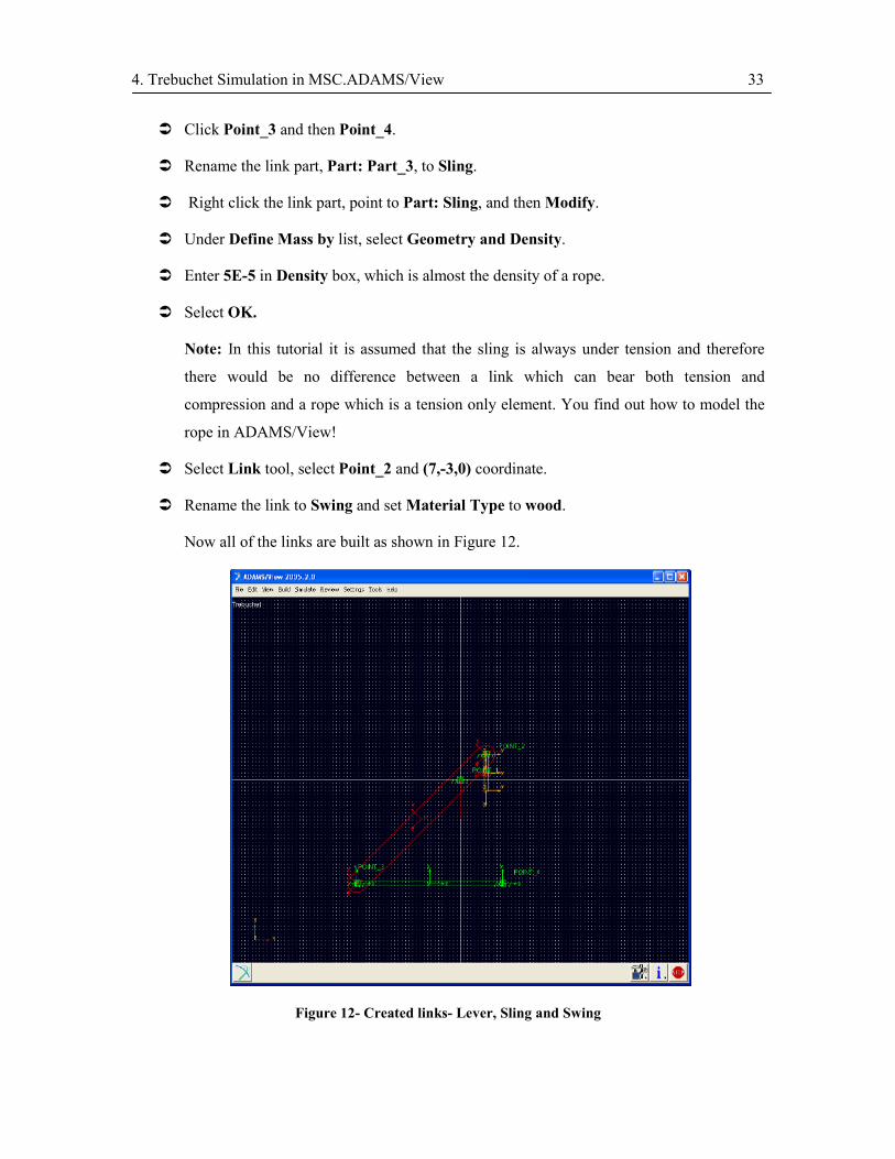
� Select Link tool, select Point_2 and (7,-3,0) coordinate.
� Rename the link to Swing and set Material Type to wood.
Now all of the links are built as shown in Figure 12.
Figure 12- Created links- Lever, Sling and Swing
4. Trebuchet Simulation in MSC.ADAMS/View 34
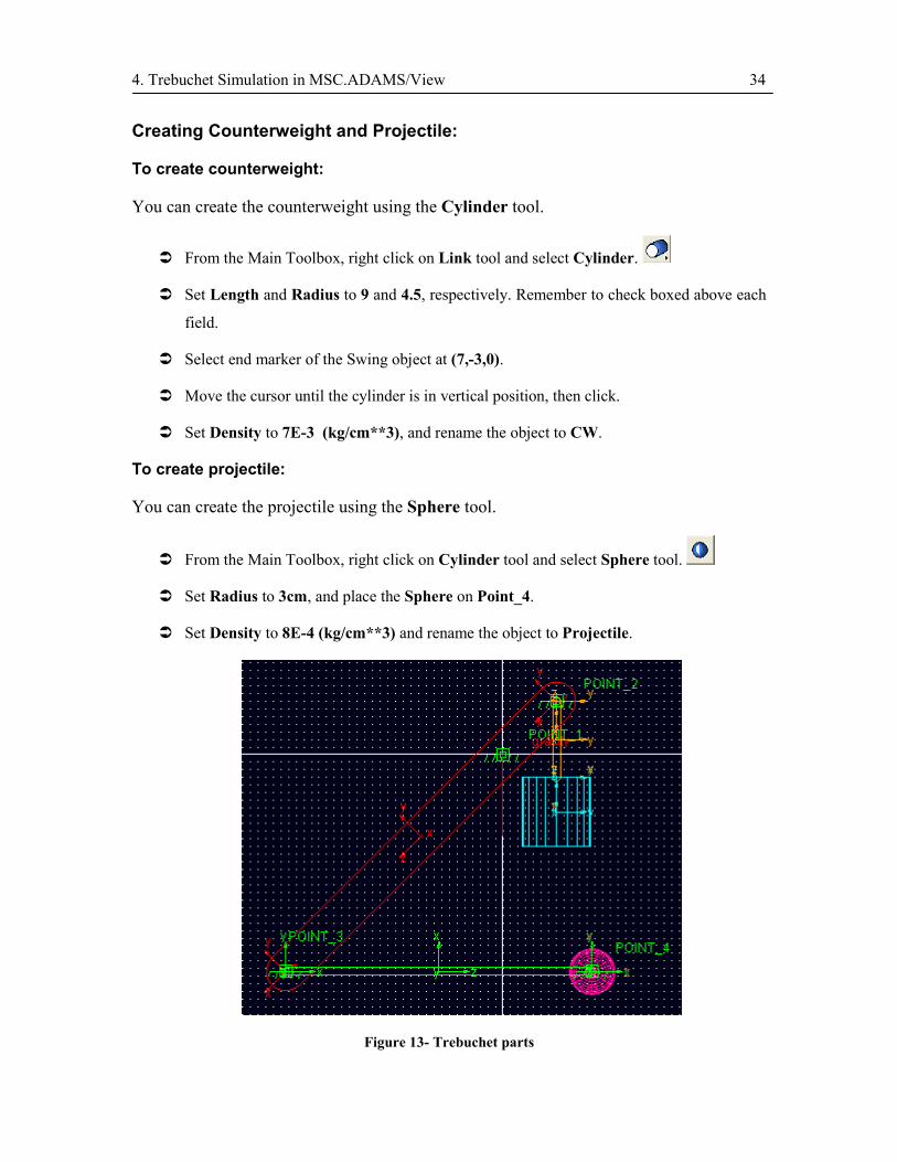
Creating Counterweight and Projectile:
To create counterweight:
You can create the counterweight using the Cylinder tool.
� From the Main Toolbox, right click on Link tool and select Cylinder.
� Set Length and Radius to 9 and 4.5, respectively. Remember to check boxed above each
field.
� Select end marker of the Swing object at (7,-3,0).
� Move the cursor until the cylinder is in vertical position, then click.
� Set Density to 7E-3 (kg/cm**3), and rename the object to CW.
To create projectile:
You can create the projectile using the Sphere tool.
� From the Main Toolbox, right click on Cylinder tool and select Sphere tool.
� Set Radius to 3cm, and place the Sphere on Point_4.
� Set Density to 8E-4 (kg/cm**3) and rename the object to Projectile.
Figure 13- Trebuchet parts
4. Trebuchet Simulation in MSC.ADAMS/View 35
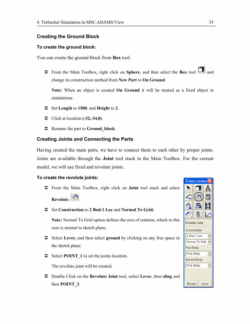
Creating the Ground Block
To create the ground block:
You can create the ground block from Box tool.
� From the Main Toolbox, right click on Sphere, and then select the Box tool and
change its construction method from New Part to On Ground.
Note: When an object is created On Ground it will be treated as a fixed object in
simulations.
� Set Length to 1500, and Height to 2.
� Click at location (-32,-34,0).
� Rename the part to Ground_block.
Creating Joints and Connecting the Parts
Having created the main parts, we have to connect them to each other by proper joints.
Joints are available through the Joint tool stack in the Main Toolbox. For the current
model, we will use fixed and revolute joints.
To create the revolute joints:
� From the Main Toolbox, right click on Joint tool stack and select
Revolute.
� Set Construction to 2 Bod-1 Loc and Normal To Grid.
Note: Normal To Grid option defines the axis of rotation, which in this
case is normal to sketch plane.
� Select Lever, and then select ground by clicking on any free space in
the sketch plane.
� Select POINT_1 to set the joints location.
The revolute joint will be created.
� Double Click on the Revolute Joint tool, select Lever, then sling and
then POINT_3.

4. Trebuchet Simulation in MSC.ADAMS/View 36
� Again Select Lever, then Swing and then POINT_2.
� Press Esc to cancel the Revolute tool.
To create fixed joints:
You can create fixed joints from the Fixed Joint tool. This joint will remove all of the
degrees of freedom that two selected bodies may have relative to each other.
� From the Main Toolbox, right click on Joint tool stack and select Fixed.
� Select Projectile, then Sling and then Point_4.
� Again select Fixed Joint tool.
� Select CW, then Swing and then the end point of the swing part.
The Fixed Joint icon appears. As you can see the size of this icon looks very large.
To modify the size:
� Right click on JOINT_4 (Fixed joint between Projectile and Sling), and point to
Appearance.
� Set Icon Size to 2.5.
� Repeat this procedure for JOINT_5 (Fixed joint between CW and Swing).
Now the initial model is almost built and can be simulated.
Figure 14- Final trebuchet model
4. Trebuchet Simulation in MSC.ADAMS/View 37
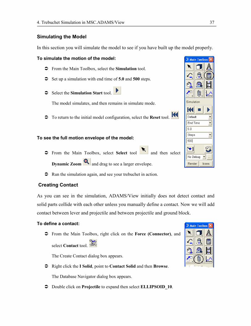
Simulating the Model
In this section you will simulate the model to see if you have built up the model properly.
To simulate the motion of the model:
� From the Main Toolbox, select the Simulation tool.
� Set up a simulation with end time of 5.0 and 500 steps.
� Select the Simulation Start tool.
The model simulates, and then remains in simulate mode.
� To return to the initial model configuration, select the Reset tool.
To see the full motion envelope of the model:
� From the Main Toolbox, select Select tool and then select
Dynamic Zoom and drag to see a larger envelope.
� Run the simulation again, and see your trebuchet in action.
Creating Contact
As you can see in the simulation, ADAMS/View initially does not detect contact and
solid parts collide with each other unless you manually define a contact. Now we will add
contact between lever and projectile and between projectile and ground block.
To define a contact:
� From the Main Toolbox, right click on the Force (Connector), and
select Contact tool.
The Create Contact dialog box appears.
� Right click the I Solid, point to Contact Solid and then Browse.
The Database Navigator dialog box appears.
� Double click on Projectile to expand then select ELLIPSOID_10.
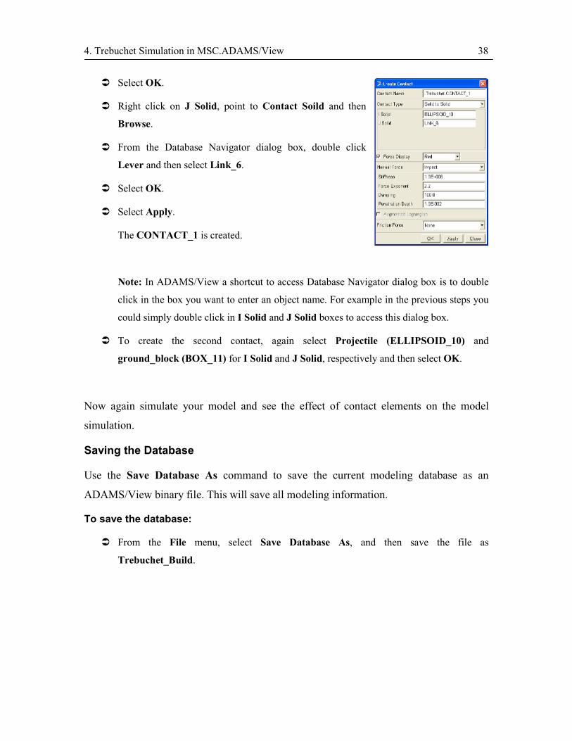
4. Trebuchet Simulation in MSC.ADAMS/View 38
� Select OK.
� Right click on J Solid, point to Contact Soild and then
Browse.
� From the Database Navigator dialog box, double click
Lever and then select Link_6.
� Select OK.
� Select Apply.
The CONTACT_1 is created.
Note: In ADAMS/View a shortcut to access Database Navigator dialog box is to double
click in the box you want to enter an object name. For example in the previous steps you
could simply double click in I Solid and J Solid boxes to access this dialog box.
� To create the second contact, again select Projectile (ELLIPSOID_10) and
ground_block (BOX_11) for I Solid and J Solid, respectively and then select OK.
Now again simulate your model and see the effect of contact elements on the model
simulation.
Saving the Database
Use the Save Database As command to save the current modeling database as an
ADAMS/View binary file. This will save all modeling information.
To save the database:
� From the File menu, select Save Database As, and then save the file as
Trebuchet_Build.

4. Trebuchet Simulation in MSC.ADAMS/View 39
4.4. Testing the Model
In this section you will complete your model and do some initial measurements. You will
also add some sensors for modeling the projectile release.
Measuring the Projectile Velocity
In ADAMS/View, it is possible to measure kinematics and dynamics of objects.
Measures are used to measure parameters like displacement, velocity, acceleration and
etc.
To add a measure on projectile velocity:
� Right click on Projectile, and point to Part: Projectile and then Measure.
The Part Measure dialog box appears. (Figure 15)
� From the Characteristics list select CM Velocity.
Note: in ADAMS/View, CM is an abbreviation of Center of Mass.
� Set Component to mag (Magnitude).
� Rename the Measure Name to Projectile_VEL.
� Select OK.
Figure 15- Part Measure dialog box

4. Trebuchet Simulation in MSC.ADAMS/View 40
The Projectile_VEL strip chart appears, showing a graph of projectile velocity in the last
simulation.
Figure 16- Projectile velocity strip chart
Creating a Sensor
Now it is the time to take the final step in modeling our trebuchet; i.e. setting an angle
that the projectile can be released from the sling.
A simple method to model the releasing process is to somehow set a parameter that the
projectile will be released when this parameter becomes true. In ADAMS/View this
situation where we need to change a condition during the simulation is detected by a
sensor and this parameter is defined by the sensor value. For example in our case, the
projectile should be released when the projectile velocity component has an angle of 45º
to the x-axis. For this purpose we will define a sensor that measures the projectile
velocity and when its value becomes equal or grater than 45º it will deactivate the fixed
joint letting the projectile to be released.
About sensors:
In general you can use sensors to trigger actions during simulations when a specified
event occurs. The actions you can trigger include:
- Stopping the simulation completely – You might want to monitor the vertical distance
between a wheel center (vehicle application) and the ground to stop the simulation when
it exceeds the undeformed radius of the tire.

4. Trebuchet Simulation in MSC.ADAMS/View 41
- Changing the parameters controlling the solution – You might want to monitor the
distance between two objects that are expected to collide during a simulation. Just before
the objects collide, you reduce the solution step size to avoid convergence problems and
reduce the output size step to capture the magnitude of the contact force.
- Changing inputs to the simulation – Sensors are often used in vehicle applications for
accommodate transition between different maneuvers, such as transition from a
controlled, straight line movement to J-turn. Any characteristic of the vehicle’s
movement that can be measured in ADAMS/View can be monitored through sensors and
trigger a change in simulation conditions.
- Changing the model topology – You can create a sensor that monitors the reaction
force in a connection and then deactivates the connection when force exceeds a specified
value.
To create a sensor to trigger the projectile release:
You can create a senor to trigger the projectile release when the velocity vector of the
projectile makes a 20º angle with x-axis direction. The velocity angle is defined
asx
y
VV
=θtan , so at °= 20θ , the value of x
y
VV
will be equal to 364.020tan =° . Therefore,
you can create a sensor that measures the value ofx
y
VV
, and when this value is equal or
greater than 0.364, the sensor triggers. Since this sensor has two solution to the trebuchet
case, you will first add a sensor that will be triggered when the x-component of the
projectile velocity becomes positive, that is a point after which the trebuchet will shoot
the projectile forward and not backward!, and then you will activate the main sensor to
release the projectile at 20º.
� Follow the previous procedure on page 39 and create two
Measures for X-Component and Y-Component of
projectile velocity and rename them to Projectile_VELX
and Projectile_VELY, respectively.
� From Simulate drop down menu, point to Sensor and then
New.
4. Trebuchet Simulation in MSC.ADAMS/View 42
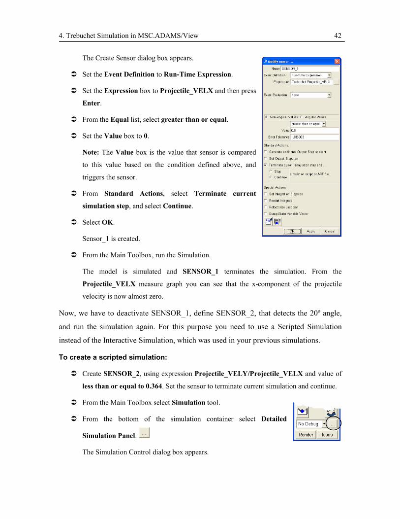
The Create Sensor dialog box appears.
� Set the Event Definition to Run-Time Expression.
� Set the Expression box to Projectile_VELX and then press
Enter.
� From the Equal list, select greater than or equal.
� Set the Value box to 0.
Note: The Value box is the value that sensor is compared
to this value based on the condition defined above, and
triggers the sensor.
� From Standard Actions, select Terminate current
simulation step, and select Continue.
� Select OK.
Sensor_1 is created.
� From the Main Toolbox, run the Simulation.
The model is simulated and SENSOR_1 terminates the simulation. From the
Projectile_VELX measure graph you can see that the x-component of the projectile
velocity is now almost zero.
Now, we have to deactivate SENSOR_1, define SENSOR_2, that detects the 20º angle,
and run the simulation again. For this purpose you need to use a Scripted Simulation
instead of the Interactive Simulation, which was used in your previous simulations.
To create a scripted simulation:
� Create SENSOR_2, using expression Projectile_VELY/Projectile_VELX and value of
less than or equal to 0.364. Set the sensor to terminate current simulation and continue.
� From the Main Toolbox select Simulation tool.
� From the bottom of the simulation container select Detailed
Simulation Panel.
The Simulation Control dialog box appears.

4. Trebuchet Simulation in MSC.ADAMS/View 43
� From the bottom of Simulation Control dialog box, select Scripted.
� Right click on Simulation Script Name box, point to Simulation_Script and then
Create.
The Create Simulation Script dialog box appears.
Figure 17- Create Simulation Script dialog box

4. Trebuchet Simulation in MSC.ADAMS/View 44
� From the Script Type list, select ADAMS/Solver Commands.
� From the Append ACF Command list, select Deactivate.
The Deactivate dialog box appears.
Figure 18- Deactivate dialog box
� In Sensor Name box, write SENSOR_2.
Note: sensors are normally active when you create them. Therefore, when you do not
need them in a part of simulation you have to first deactivate them.
� Select OK.
The DEACTIVATE/SENSOR, ID=2 command appears in ADAMS/Solver Commands
box.
� From the Append ACF Command list, select Dynamic Simulation.
The Dynamic Simulation dialog box appears.
Figure 19- Dynamic Simulation dialog box

4. Trebuchet Simulation in MSC.ADAMS/View 45
� In Number of Steps box, write 500 and in End Time, write 5.0.
� Select OK.
The SIMULATE/DYNAMIC, END=5.0, STEPS=500 appears in ADAMS/Solver
Commands box. This command performs the same routine as you previously ran the
Interactive Simulation.
� Deactivate SENSOR_1.
� From the Append ACF Command list, select Activate.
The Activate dialog box appears.
� In Sensor Name box, write SENSOR_2.
� Select OK.
The ACTIVATE/SENSOR, ID=2 appears in ADAMS/Solver Commands box.
� Again add the command for dynamic simulation for 5 seconds and 500 steps.
Note: If you know any command, you can simply type it in the ADAMS/Solver
Commands box, instead of using the Append ACF Command list.
� Deactivate SENSOR_2.
Now it is the time to deactivate JOINT_4, the fixed joint that fixes projectile to sling, in
order to release the projectile.
� From Append ACF Command list, select Deactivate.
The Deactivate dialog box appears.
� In Joint Name box, pick JOINT_4.
� Clear all other boxes, and Select OK.
Figure 20- Deactivate dialog box
4. Trebuchet Simulation in MSC.ADAMS/View 46
� Again add the command for dynamic simulation for 5 seconds but since here you don’t
need to use too many time steps to solve the model, set Steps to 300. This will increase
the speed of simulation.
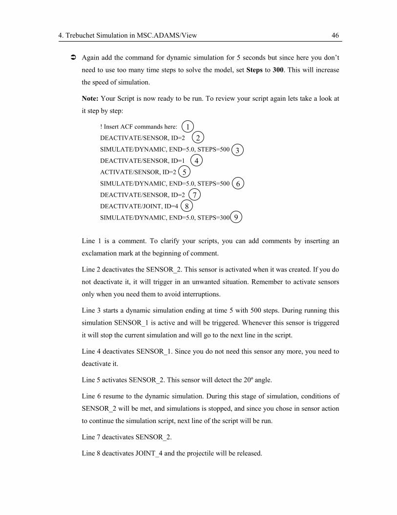
Note: Your Script is now ready to be run. To review your script again lets take a look at
it step by step:
! Insert ACF commands here:
DEACTIVATE/SENSOR, ID=2
SIMULATE/DYNAMIC, END=5.0, STEPS=500
DEACTIVATE/SENSOR, ID=1
ACTIVATE/SENSOR, ID=2
SIMULATE/DYNAMIC, END=5.0, STEPS=500
DEACTIVATE/SENSOR, ID=2
DEACTIVATE/JOINT, ID=4
SIMULATE/DYNAMIC, END=5.0, STEPS=300
Line 1 is a comment. To clarify your scripts, you can add comments by inserting an
exclamation mark at the beginning of comment.
Line 2 deactivates the SENSOR_2. This sensor is activated when it was created. If you do
not deactivate it, it will trigger in an unwanted situation. Remember to activate sensors
only when you need them to avoid interruptions.
Line 3 starts a dynamic simulation ending at time 5 with 500 steps. During running this
simulation SENSOR_1 is active and will be triggered. Whenever this sensor is triggered
it will stop the current simulation and will go to the next line in the script.
Line 4 deactivates SENSOR_1. Since you do not need this sensor any more, you need to
deactivate it.
Line 5 activates SENSOR_2. This sensor will detect the 20º angle.
Line 6 resume to the dynamic simulation. During this stage of simulation, conditions of
SENSOR_2 will be met, and simulations is stopped, and since you chose in sensor action
to continue the simulation script, next line of the script will be run.
Line 7 deactivates SENSOR_2.
Line 8 deactivates JOINT_4 and the projectile will be released.
23
45
67
8
1
9
4. Trebuchet Simulation in MSC.ADAMS/View 47
Line 9 again resume to dynamic simulation with 300 steps. The simulation will be
stopped at time 5.0 and since there are no more commands it will be completely stopped.
� Select OK.
SIM_SCRIPT_1 appears in Simulation Script Name box in Simulation Control dialog
box.
� Fit your view and run the simulation.
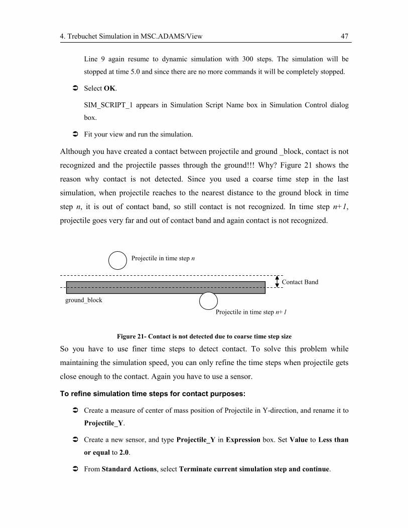
Although you have created a contact between projectile and ground _block, contact is not
recognized and the projectile passes through the ground!!! Why? Figure 21 shows the
reason why contact is not detected. Since you used a coarse time step in the last
simulation, when projectile reaches to the nearest distance to the ground block in time
step n, it is out of contact band, so still contact is not recognized. In time step n+1,
projectile goes very far and out of contact band and again contact is not recognized.
Figure 21- Contact is not detected due to coarse time step size
So you have to use finer time steps to detect contact. To solve this problem while
maintaining the simulation speed, you can only refine the time steps when projectile gets
close enough to the contact. Again you have to use a sensor.
To refine simulation time steps for contact purposes:
� Create a measure of center of mass position of Projectile in Y-direction, and rename it to
Projectile_Y.
� Create a new sensor, and type Projectile_Y in Expression box. Set Value to Less than
or equal to 2.0.
� From Standard Actions, select Terminate current simulation step and continue.
Projectile in time step n
Contact Band
Projectile in time step n+1
ground_block
4. Trebuchet Simulation in MSC.ADAMS/View 48
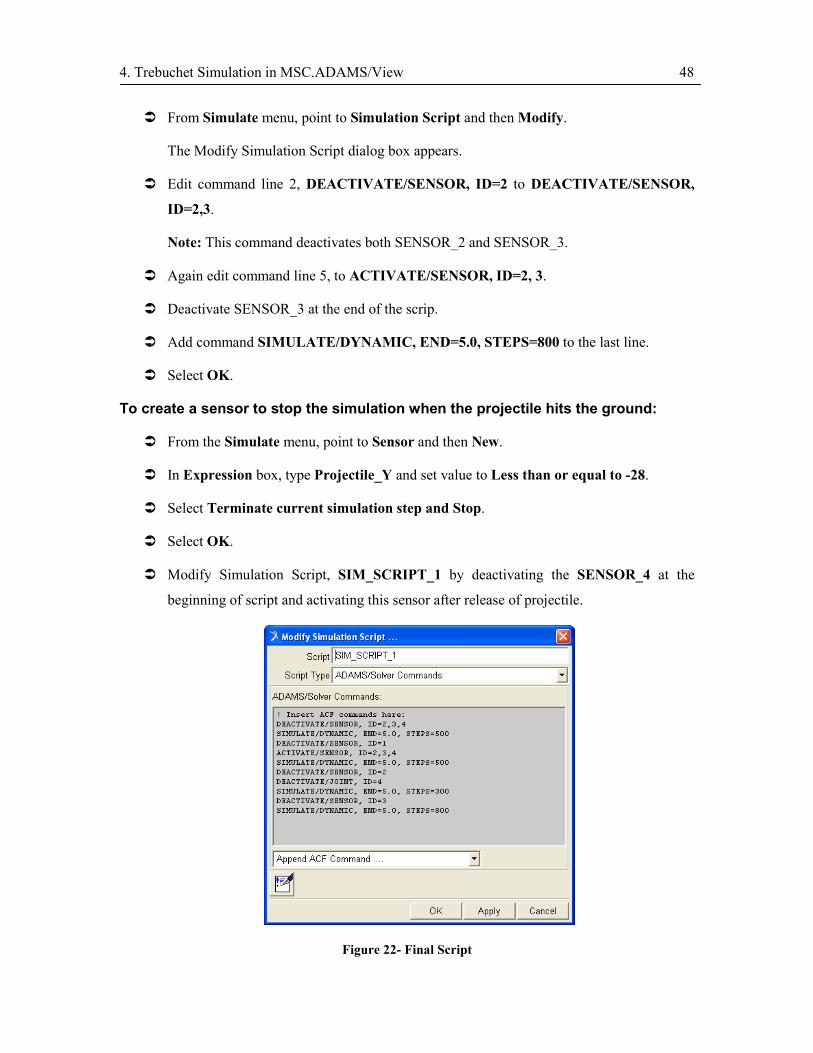
� From Simulate menu, point to Simulation Script and then Modify.
The Modify Simulation Script dialog box appears.
� Edit command line 2, DEACTIVATE/SENSOR, ID=2 to DEACTIVATE/SENSOR,
ID=2,3.
Note: This command deactivates both SENSOR_2 and SENSOR_3.
� Again edit command line 5, to ACTIVATE/SENSOR, ID=2, 3.
� Deactivate SENSOR_3 at the end of the scrip.
� Add command SIMULATE/DYNAMIC, END=5.0, STEPS=800 to the last line.
� Select OK.
To create a sensor to stop the simulation when the projectile hits the ground:
� From the Simulate menu, point to Sensor and then New.
� In Expression box, type Projectile_Y and set value to Less than or equal to -28.
� Select Terminate current simulation step and Stop.
� Select OK.
� Modify Simulation Script, SIM_SCRIPT_1 by deactivating the SENSOR_4 at the
beginning of script and activating this sensor after release of projectile.
Figure 22- Final Script
4. Trebuchet Simulation in MSC.ADAMS/View 49
� Fit the model view and run the Scripted Simulation.
To save the current simulation:
� At the bottom of the Simulation control dialog box, select Save the last simulation
results.
The Save Run Results dialog box appears.
� In the Name box, type RUN_1, and Select OK.
Plotting the Projectile Trajectory
To plot the projectile trajectory:
� Create a measure of center of mass of Projectile position along x-axis, and rename it to
Projectile_X.
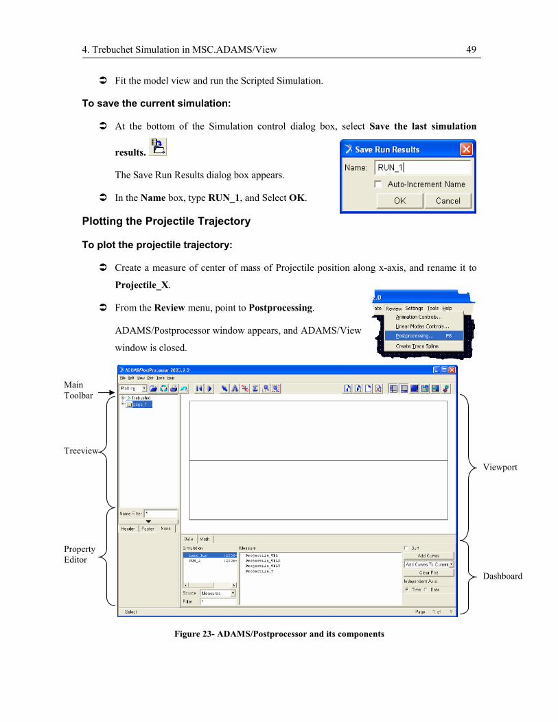
� From the Review menu, point to Postprocessing.
ADAMS/Postprocessor window appears, and ADAMS/View
window is closed.
Figure 23- ADAMS/Postprocessor and its components
Viewport
Dashboard
Property Editor
Treeview
Main Toolbar

4. Trebuchet Simulation in MSC.ADAMS/View 50
� From the Tree view on the left side of window, expand page_1, and select plot_1.
� In the Dashboard at the bottom of the window, from Simulation list, select RUN_1.
� From Source list, select Measures.
� In the Dashboard, from the Measure list, select Projectile_Y.
� In the Dashboard, from Independent Axis, select Data.
The Independent Axis Browser Dashboard appears.
� Select RUN_1, then Projectile_X.
� Select OK.
� From the Dashboard, select Add Curves button.
The projectile trajectory curve is created.
Figure 24- Projectile trajectory
To make measurements on the curve:
� From the Main toolbar, select Plot tracking.
� Move the cursor on the curve and see measured values.

4. Trebuchet Simulation in MSC.ADAMS/View 51
To edit curve title and labels:
� From Treeview, under plot_1, select title.
A window appears in Property Editor under the Treeview.
� In the name box, type Projectile Trajectory. (currently the text
‘trebuchet’ is written in the name box)
� From Treeview, under plot_1, select haxis.
A window appears in Property Editor.
Note: haxis represents Horizontal Axis of the curve.
� From the Tabs, select Label, and in Label box, type Range (cm).
� Repeat the same procedure for Vertical Axis (vaxis) and type the label Height (cm).
Note: you can change other properties of these parameters like font size, orientation, etc.
� Close ADAMS/Postprocessor window to automatically return to ADAMS/View.
Adding Joint Friction
Normally there exists friction in joints, which highly affects performance of the device. In
this section you add friction to the pivot joint, and investigate its effect on projectile
trajectory.
To add joint friction:
You can add joint friction by modifying the joint.
� Right click on JOINT_1 (the lever pivot), and point to
Modify.
The Modify Joint dialog box appears.
� From the bottom of the dialog box, select Joint
Friction.
The Create Friction dialog box appears.
� In Mu Static box, type, 0.2.
� In Mu Dynamic box, type 0.1.

4. Trebuchet Simulation in MSC.ADAMS/View 52
Note: Mu Static and Mu Dynamic, represent static and dynamic friction coefficients,
respectively.
� Select OK.
� In Modify Joint dialog box, select OK.
� Run Scripted Simulation and save the simulation as RUN_2.
To investigate the effect of joint friction on trajectory:
� Switch to ADAMS/Postprocessor.
� From the Dashboard, select RUN_2 from Simulation list, and then Projectile_Y from
Measures.
� From the drop down list, select Add Curves to Current, and then press Add Curve
Button.
A new curve, showing the effect of friction coefficient on projectile trajectory is created.
Figure 25- Projectile trajectory, with (red line) and without (blue dashed line) joint friction in pivot
4. Trebuchet Simulation in MSC.ADAMS/View 53
� Close ADAMS/Postprocessor window to return to ADAMS/View.
To delete joint friction:
� Deselect all of the objects by clicking anywhere in free space away from objects or by
pressing Esc two times.
� From the Edit drop down menu, point to Delete.
The Database Navigator dialog box appears.
� From the list under Trebuchet, select FRICTION_1.
� Select OK.
Adding Drag Force on Projectile
Drag force exerted on the projectile is also an important source of energy dissipation
which results in a change in the projectile trajectory.
The drag force is defined as
2
21 AVcF aDD ρ=
where
Dc is the drag coefficient, and for sphere it equals to ~2,
aρ is the density of air which is almost 32.1 mkg ,
A is the cross sectional area of the projectile, which for the current projectile
is 241027.28 m−× ,
V is the projectile velocity.
Since this force acts in the reverse direction of velocity vector and is a vector quantity,
you can compute this force on X and Y directions separately and apply the components to
the center of mass of the projectile.
4. Trebuchet Simulation in MSC.ADAMS/View 54
To add drag force to projectile:
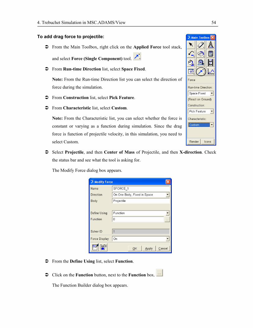
� From the Main Toolbox, right click on the Applied Force tool stack,
and select Force (Single Component) tool.
� From Run-time Direction list, select Space Fixed.
Note: From the Run-time Direction list you can select the direction of
force during the simulation.
� From Construction list, select Pick Feature.
� From Characteristic list, select Custom.
Note: From the Characteristic list, you can select whether the force is
constant or varying as a function during simulation. Since the drag
force is function of projectile velocity, in this simulation, you need to
select Custom.
� Select Projectile, and then Center of Mass of Projectile, and then X-direction. Check
the status bar and see what the tool is asking for.
The Modify Force dialog box appears.
� From the Define Using list, select Function.
� Click on the Function button, next to the Function box.
The Function Builder dialog box appears.

4. Trebuchet Simulation in MSC.ADAMS/View 55
Figure 26- Function Builder dialog box
In this box you define the drag force in X-direction.
� In Function Work Area, type 0.5*0.5*1.2*28.27E-4*(Projectile_VELX*1E-2) **2.
Note: The ** sign represents the power operator.
� Click on Plot button to view the value of this function.
� Close the graph.
Note: This value is the magnitude of the force. Since the force is always in the reverse
direction of velocity, we can add a sign() function to correct the value of force.
� From the Function Category list, select Math Functions.
� From list of functions, double click on SIGN.
List of Functions
Function Categories
Function Work Area Operators
Verify Expression
Get Predefined Data
Plot Result of Function
Get Help with System Supplied Function

4. Trebuchet Simulation in MSC.ADAMS/View 56
The general form of SIGN function appears in Function Work Area as SIGN(x1, x2).
This function applies the sign of expression x2 to expression x1.
� Edit the function, as
-1*SIGN(.5*0.5*1.2*28.27E-4*(Projectile_VELX*1E-2)**2, Projectile_VELX).
Note: This function applies the reverse sign of projectile velocity to the drag force
magnitude.
� Select OK in Function Builder dialog box, then select OK in Modify Force dialog box..
The drag force component along x-axis, SFORCE_1, is now created.
� Repeat the above procedure for the Y component of drag force.
Note: Remember to choose the Y-axis when you are asked to choose the vector direction.
Use Y component of projectile velocity, Projectile_VELY in drag force function. The
function should look like:
-1*SIGN(.5*0.5*1.2*28.27E-4*(Projectile_VELY*1E-2)**2, Projectile_VELY)
To investigate the effect of drag force on projectile trajectory:
� Run a Scripted Simulation.
� Save simulation as RUN_3.
� Switch to ADAMS/Postprocessor.
� From the Dashboard, select RUN_3, then Projectile_Y.
� From the drop down list, select Add Curves to Current, and then press Add Curve.
A new curve, showing the effect of drag force on projectile trajectory is created.

4. Trebuchet Simulation in MSC.ADAMS/View 57
Figure 27- Projectile trajectory without dissipative forces (solid), with friction only (blue dashed) and with drag force only (red dashed)
� Close ADAMS/Postprocessor window to return to ADAMS/View.
To delete drag force:
� Deselect all objects.
� Under Edit menu, select Delete.
� From the Database Navigator, select SFORCE_1, select OK.
� Repeat the procedure for SFORCE_2.
� Save database as Trebuchet_Test.
4.5. Improving the Model (Optimization)
In this section you refine your model by parameterizing some critical values that can
affect the performance of the trebuchet, and then you study the effect of these parameters
and optimize the model based on these parameters.
There are many parameters that affect the performance of a trebuchet. However, in the
current tutorial three critical parameters, namely lever beam mass, sling length and
release angle will be studied, and the performance of trebuchet, which is defined as the
maximum range of projectile, will be optimized.

4. Trebuchet Simulation in MSC.ADAMS/View 58
It should be noted that there are many other parameters that influences the performance
of the trebuchet and you need to consider them in your design.
Parameterizing the Critical Values
The model that you made up to this stage consists of values that are all fixed, i.e. the
lengths, masses and geometrical constraints are pre-defined constants. In order to conduct
a design study and improve your model, you need to set variable parameters that can be
easily changed, so that you can see the effect of these parameters on the performance of
the model.
To create a design variable for lever beam mass:
� Right click on the Lever object, point to Part: Lever, and then Modify.
The Modify Body dialog box appears.
� From the Define Mass By list, select
Geometry and Density.
� Right click on Density box, point to
Parameterize and then Create
Design Variable.
The (.Trebuchet.DV_1) expression appears in the box. This will be the design variable
that further represents the value of lever mass.
� Select OK.
To create a design variable for release angle:
You can create a design variable representing the release angle, that has standard value of
20º and can be changed between 0º to 80º.
� From the Build menu, point to Design Variable and then New.
The Create Design Variable dialog box appears.
� In Standard Value box, type 20.

4. Trebuchet Simulation in MSC.ADAMS/View 59
� From Value Range by list, select Absolute Min
and Max Values.
� In Min. Value box, type 0.
� In Max. Value box, type 80.
� Select OK.
Since we have defined SENSOR_2 based on the value of this angle, we have to now
change this value in the sensor definition.
� From the Simulate menu, point to Sensor, and then Modify.
The Database Navigator dialog box appears.
� Select SENSOR_2 and then OK.
The Modify Sensor dialog box appears.
� Right click on the Value box, point to Parameterize and then Expression Builder.
The Function Builder dialog box appears.
� In Function Work Area box, type TAN (DV_2).
� Select OK.
The (TAN (DV_2)) expression appears in Value box.
� Select OK.
To create a design variable for sling length:
You can change the value of sling length by setting a design variable to the x-location of
POINT_4. Remember that you have used these points for model construction so that you
can change the model layout by simply changing the position of these points.
� Right click on Point_4 (end point of sling), and then point to Modify
The Table Editor for Points dialog box appears. (Figure 28)
� Click on Loc_X of POINT_4.
� Right click on the Input box on top of the Table Editor, and point to Parameterize, then
Create Design Variable and then Real.
The (Trebuchet.DV_3) expression appears in Loc_X of POINT_4.
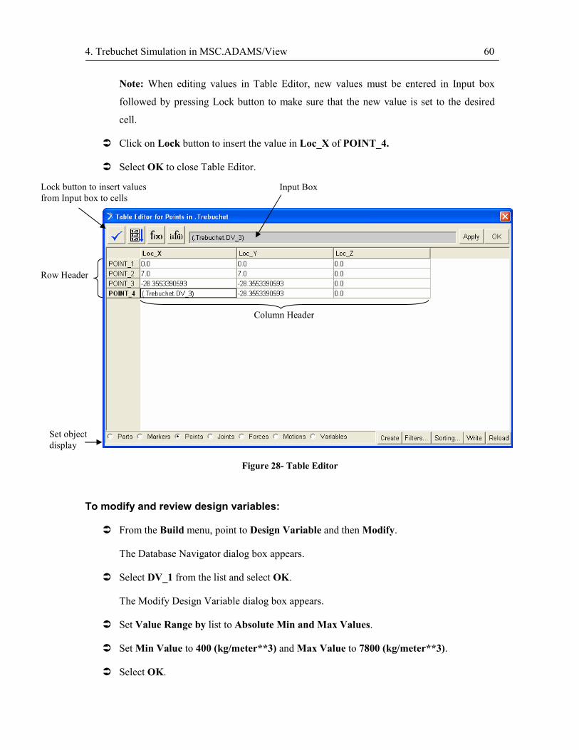
4. Trebuchet Simulation in MSC.ADAMS/View 60
Note: When editing values in Table Editor, new values must be entered in Input box
followed by pressing Lock button to make sure that the new value is set to the desired
cell.
� Click on Lock button to insert the value in Loc_X of POINT_4.
� Select OK to close Table Editor.
Figure 28- Table Editor
To modify and review design variables:
� From the Build menu, point to Design Variable and then Modify.
The Database Navigator dialog box appears.
� Select DV_1 from the list and select OK.
The Modify Design Variable dialog box appears.
� Set Value Range by list to Absolute Min and Max Values.
� Set Min Value to 400 (kg/meter**3) and Max Value to 7800 (kg/meter**3).
� Select OK.
Input Box Lock button to insert values from Input box to cells
Row Header
Column Header
Set object display

4. Trebuchet Simulation in MSC.ADAMS/View 61
� Follow the same procedure to modify DV_3.
� Set Value Range by list to Absolute Min and Max Values.
� Set Min Value to -15.0 and Max Value to 20.0.
� Select OK.
Performing a Manual Study
In this section you can see the effect of sling length on the projectile velocity by manually
changing the value of DV_3, the design variable assigned to sling length.
To perform a manual study:
� From the Tools menu, select Table Editor.
The Table Editor dialog box appears.
� From Set object display row at the bottom of the dialog box select Variables.
� From the Table Editor, change the Real_Value of DV_3 to 20.0.
� Select Apply.
Note: Always remember to press Apply or OK to apply changes to your model layout.
� Run a Scripted Simulation.
� From the Build menu, point to Measure and then Display.
The Database Navigator box appears.
� From the list select Projectile_X, and then OK.
The Projectile_X graph appears.
� Right click on the red curve in graph and point to Curve: Current and then Save Curve.
The curve color changes from red to blue and is now named Saved1.
� From the Table Editor, change the Real_Value of DV_3 to -10.0, and then press Enter.
� Select Appply.
� Run a Scripted Simulation.
From the Projectile_X measure graph see the effect of sling length on range efficiency.
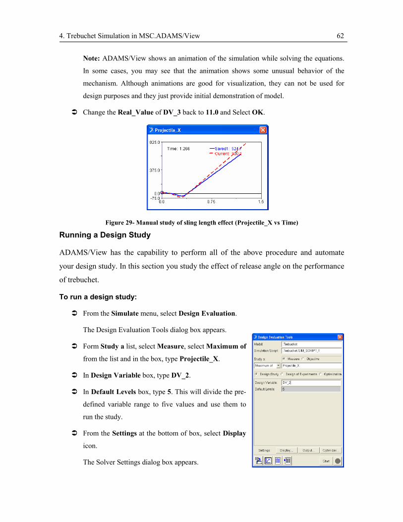
4. Trebuchet Simulation in MSC.ADAMS/View 62
Note: ADAMS/View shows an animation of the simulation while solving the equations.
In some cases, you may see that the animation shows some unusual behavior of the
mechanism. Although animations are good for visualization, they can not be used for
design purposes and they just provide initial demonstration of model.
� Change the Real_Value of DV_3 back to 11.0 and Select OK.
Figure 29- Manual study of sling length effect (Projectile_X vs Time)
Running a Design Study
ADAMS/View has the capability to perform all of the above procedure and automate
your design study. In this section you study the effect of release angle on the performance
of trebuchet.
To run a design study:
� From the Simulate menu, select Design Evaluation.
The Design Evaluation Tools dialog box appears.
� Form Study a list, select Measure, select Maximum of
from the list and in the box, type Projectile_X.
� In Design Variable box, type DV_2.
� In Default Levels box, type 5. This will divide the pre-
defined variable range to five values and use them to
run the study.
� From the Settings at the bottom of box, select Display
icon.
The Solver Settings dialog box appears.
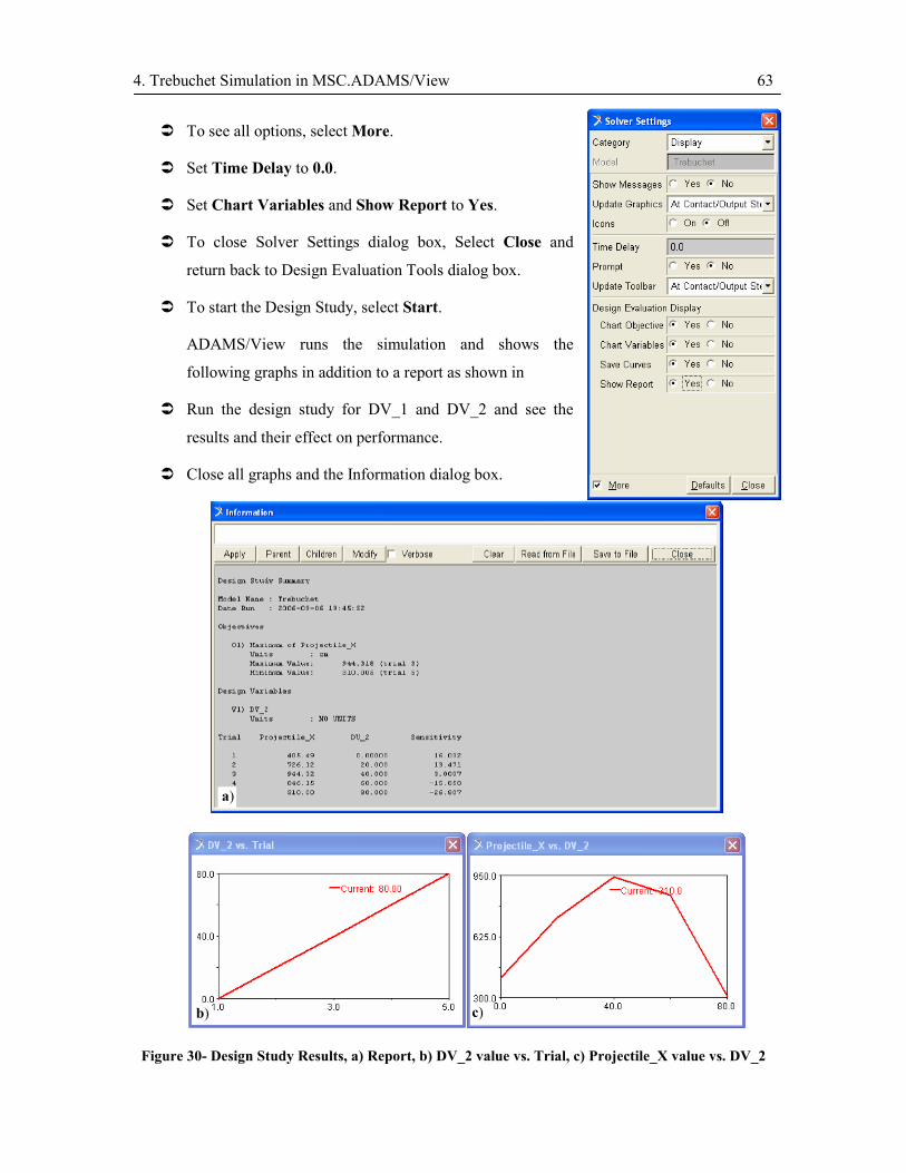
4. Trebuchet Simulation in MSC.ADAMS/View 63
� To see all options, select More.
� Set Time Delay to 0.0.
� Set Chart Variables and Show Report to Yes.
� To close Solver Settings dialog box, Select Close and
return back to Design Evaluation Tools dialog box.
� To start the Design Study, select Start.
ADAMS/View runs the simulation and shows the
following graphs in addition to a report as shown in
� Run the design study for DV_1 and DV_2 and see the
results and their effect on performance.
� Close all graphs and the Information dialog box.
Figure 30- Design Study Results, a) Report, b) DV_2 value vs. Trial, c) Projectile_X value vs. DV_2
a)
b) c)

4. Trebuchet Simulation in MSC.ADAMS/View 64
Running an Optimization
You will now find the optimum design for your trebuchet considering only the effect of
chosen design variables. As you saw in the design study, mass of the beam is inversely
proportional to the performance. So based on the strength considerations the lowest
weight/strength will suffice your optimum design. Therefore, in device optimization you
only optimize values of sling length and release angle. As you can see at the end of this
section, optimization is a very time consuming process and running a good design study
will help you choose better design variables and come to an optimized solution faster.
To perform an optimization:
� From Design Evaluation dialog box, select
Optimization.
� In Design Variables box, type DV_2, press Enter, and
then type DV_3.
� From Settings, select Optimizer button.
The Solver Settings dialog box appears.
� Select OPTDES-SQP from the Algorithm list.
� In Tolerance box, type 1E-3.
� In Increment box, type 1E-6.
Note: The optimization process is highly dependant on
values of tolerance and increment. Try different values in
your design process to come to the real optimized design.
� Select Close to return back to Design Evaluation Tools
dialog box.

4. Trebuchet Simulation in MSC.ADAMS/View 65
� Again from Settings, select Output.
� From Output Category list, select Database Storage.
� Under Multi-Run Simulations, set Save Analysis to
Yes.
� Select Close.
� Start Optimization.
Note: Optimization may take several minutes to
complete, and will take several optimizations.
� When the optimization process is finished, see the
optimized values from the Information dialog box. These
values are shown in Figure 31.
Use these values to build your final optimized trebuchet!
Note 1: The optimized values will be set to your model by the software at the end of
optimization.
Note 2: Your optimization process highly depends on the tolerance, increment,
optimization algorithm, and range of design variable. In order to come to the best
optimization process, you need to try different scenarios and refine your parameters each
time.
Note 2: The trebuchet optimization is a nonlinear optimization process and may result in
different solutions (local optimized solution) by choosing different initial values. So try
different initial values and check for the best optimized values (global optimized
solution).
Note 3: Again it should be noted that this section is only intended to give you a general
overview of MSC.Adams/View to get started with this software and also learn trebuchet
dynamics. For your own design, you need to study other parameters and design layouts.
Your trebuchet may even look totally different from what is generally known as
trebuchet!

4. Trebuchet Simulation in MSC.ADAMS/View 66
Figure 31- Optimization Results, a) Report, b)Projectile_X value vs. Iteration, c) DV_2 value vs. Iteration and d) DV_3 vs. Iteration
a)
b) c)
d)

Appendix A. Counterweight Specifications 67
Appendix A. Counterweight Specifications
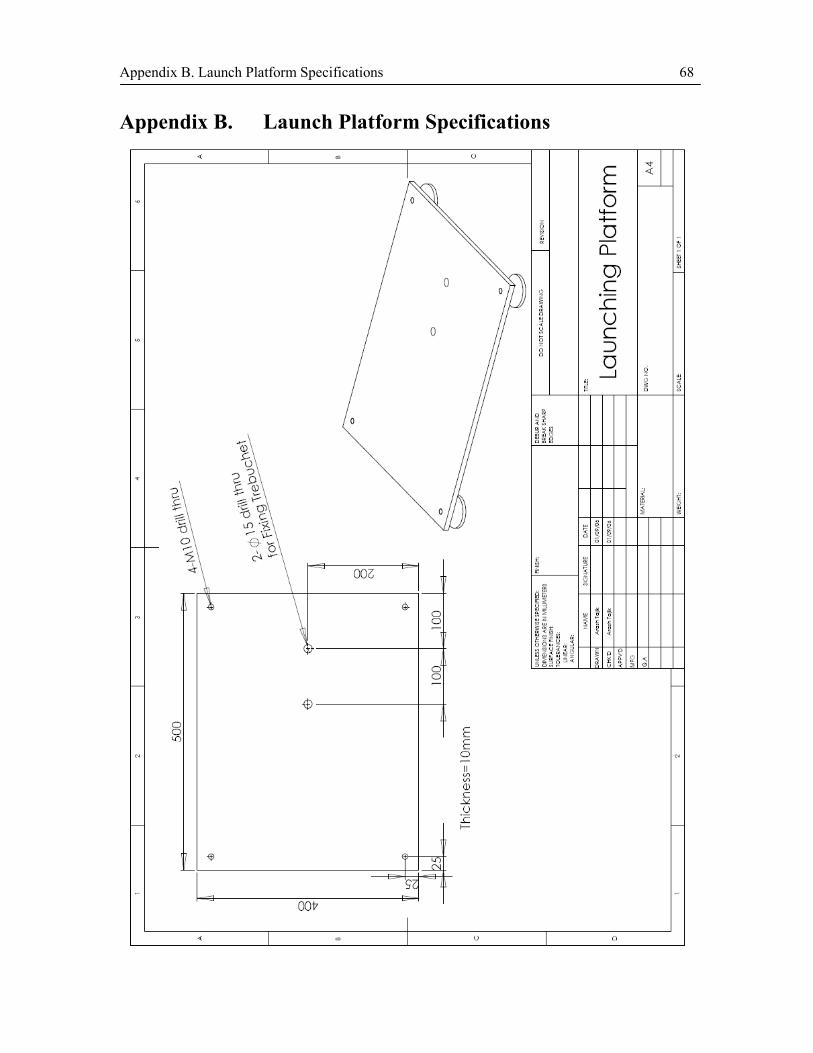
Appendix B. Launch Platform Specifications 68
Appendix B. Launch Platform Specifications

Appendix C. Report Cover Page 69
Appendix C. Report Title Page See the next following pages for report title pages.

UNIVERSITY OF WATERLOO
DEPARTMENT OF MECHANICAL ENGINEERING
ME380 – Mechanical Engineering Design Workshop
INTERIM REPORT FALL 2006
Team Number: ______
Team Members:
Name ID# Contribution % Signature
1
2
3
4
5
Marks: Preliminary Design: /15
Analysis and Design Optimization: /10
Detailed Design: /15
Total Marks for Interim Report: /40

UNIVERSITY OF WATERLOO
DEPARTMENT OF MECHANICAL ENGINEERING
ME380 – Mechanical Engineering Design Workshop
FINAL REPORT FALL 2006
Team Number: ______
Team Members:
Name ID# Contribution % Signature
1
2
3
4
5
Marks:
Interim Report: /40
Test Results: Attendance in Competition: /10
Performance: /10
Precision: /10
Creativity and Design Quality: /10
Final Report: Simulation/Experimentation Comparison: /10
Discussion: /10
Total Marks: /100
5. References 72
5. References
[1] Chevedden, P. E., Eigenbrod, L., Floey, V. and Soedel, W., “The Trebuchet”,
Scientific American, February 2002, pp. 2-5.
[2] Wikipedia, the free encyclopaedia, http://en.wikipedia.org/wiki/Trebuchet,
Available: July 2006.
[3] Ginsberg, J. H., “Advanced Engineering Dynamics”, Second Edition, Cambridge
University Press, New York, 1995.
[4] Goldstein, H., Poole, C. P., Safko, J. L., “Classical Mechanics”, Third Edition,
Addison Wily, San Francisco, 2002.
[5] Kibble, W. B., Berkshire, F. H., “Classical Mechanics”, Fifth Edition, Imperial
College Press, London, 2004.
[6] Tong, David, “Classical Dynamics”, Lecture Notes on Classical Dynamics,
University of Cambridge, 2004. http://www.damtp.cam.ac.uk/user/tong/dynamics.htm.
[7] Denny, M., “Siege Engine Dynamics”, European Journal of Physics, 26, 2005, pp.
561-577.
[8] Siano, D. B., “Trebuchet Mechanics”, http://www.algobeautytreb.com/, Available:
July 2006.
[9] Covington, M., “The Trebuchet: Physics, Numerics and Connections to Millennia of
Human Activity”, Physics Honours Thesis, University of California, Santa Cruz.
[10] Chang, H., Fu, W., Shimizu, M., Tang, C. P., “Design and development of a model
trebuchet”, MAE415 Final Project, State University of New York at Buffalo, 2000.
[11] Arnold, B., Richards, L., Wongpiromsarn, “Going Mobile: Search for Ideal
Trebuchet”, MAE479/579 Final Project, Cornell University, 2004.
[12] ADAMS/View online help, MSC.Software Corporation, 2004.


![Trebuchet versus Flinger: Millennial mechanics and bio ... · Harter - Trebuchet 3 1. Introduction The trebuchet or ingenium [1,2] was a super-catapult invented in China about 400BC](https://static.fdocuments.in/doc/165x107/5c61d37c09d3f2eb708b5d80/trebuchet-versus-flinger-millennial-mechanics-and-bio-harter-trebuchet.jpg)