Traversing final-report
25
TAYLOR’S UNIVERSITY | SABD | SITE SURVEYING (QSB 60103) | TRAVERSING REPORT 1 SCHOOL OF ARCHITECTURE, BUILDING AND DESIGN BACHELOR OF QUANTITY SURVEYING (HONOURS) QSB 60103 – SITE SURVEYING SEMESTER 2 FIELDWORK 1 REPORT TRAVERSING Name Student ID Marks Hor Weng Lim 0319441 Felix Vong Zhi Wei 0318462 Kevin Lee Hee Xian 0315192 Jackson Ting Shii Hang 0324326
-
Upload
felix-vong -
Category
Education
-
view
4.338 -
download
3
Transcript of Traversing final-report
TAYLOR’S UNIVERSITY | SABD | SITE SURVEYING (QSB 60103) | TRAVERSING REPORT
1
SCHOOL OF ARCHITECTURE, BUILDING AND DESIGN
BACHELOR OF QUANTITY SURVEYING (HONOURS)
QSB 60103 – SITE SURVEYING
SEMESTER 2
FIELDWORK 1 REPORT
TRAVERSING
Name Student ID Marks
Hor Weng Lim 0319441
Felix Vong Zhi Wei 0318462
Kevin Lee Hee Xian 0315192
Jackson Ting Shii Hang 0324326
TAYLOR’S UNIVERSITY | SABD | SITE SURVEYING (QSB 60103) | TRAVERSING REPORT
2
Content Page
Cover Page 1
Table of Content 2
1.0 Introduction to Traversing 3
1.1 Open Traverse 3
1.2 Closed Traverse 4 - 5
1.3 Northing 6
1.4 Azimuths 7
1.5 Bearing 8
2.0 Objective 9
3.0 Outline of Apparatus 10
3.1 Theodolites 10
3.2 Tripod Stand 11
3.3 Optical Plummet 12
3.4 Ranging Rod 13
3.5 Spirit Bubble 14
3.6 Plumb Bob 15
4.0 Field Data 16
4.1 Compute the Angular Error and Adjust the Angles 17
4.2 Stadia Method 18 - 19
4.3 Compute Course Bearing and Azimuth 20
4.4 Compute Course Latitude and Departure 21
4.5 Determine the Error of Closure 22
4.6 Adjust Course Latitude and Departure 23
5.0 Discussion 24
6.0 Conclusion 25
TAYLOR’S UNIVERSITY | SABD | SITE SURVEYING (QSB 60103) | TRAVERSING REPORT
3
1.0 INTRODUCTION TO TRAVERSING
Traversing is a form of a control survey that requires the establishment of a series of stations that
are linked together by angles and distance. It can be open traverse and close traverse. The angles
are measured by theodolites and the distance can be measured by calculating the stadia’s reading
or using electronic distance measuring equipment. The use of theodolites in traversing survey is
one of the most common methods in engineering work to get the provision of control surveys,
angle measurement and detail mapping.
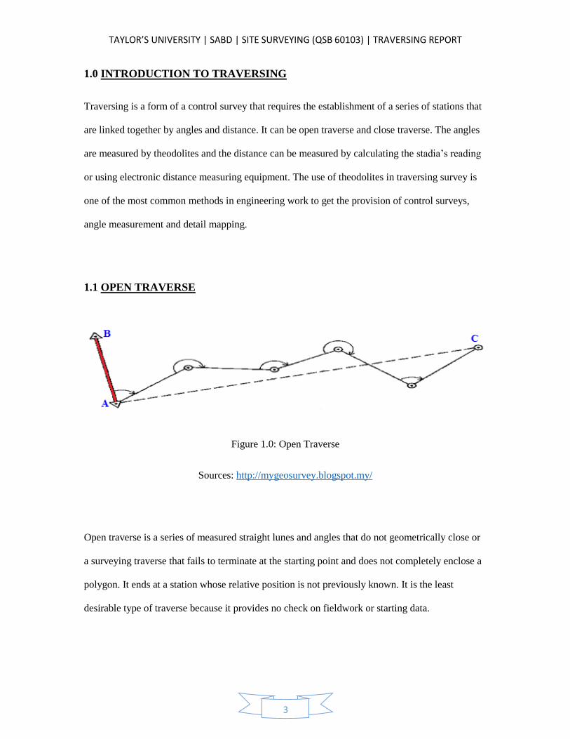
1.1 OPEN TRAVERSE
Figure 1.0: Open Traverse
Sources: http://mygeosurvey.blogspot.my/
Open traverse is a series of measured straight lunes and angles that do not geometrically close or
a surveying traverse that fails to terminate at the starting point and does not completely enclose a
polygon. It ends at a station whose relative position is not previously known. It is the least
desirable type of traverse because it provides no check on fieldwork or starting data.
TAYLOR’S UNIVERSITY | SABD | SITE SURVEYING (QSB 60103) | TRAVERSING REPORT
4
1.2 CLOSED TRAVERSE
Closed traverse is a series of connected line which end at the starting point. It is basically a
traverse proceed from one coordinate point to another. A closed traverse may be close back to its
starting point or whose relative position is known.
Closed traverse can be in two types:
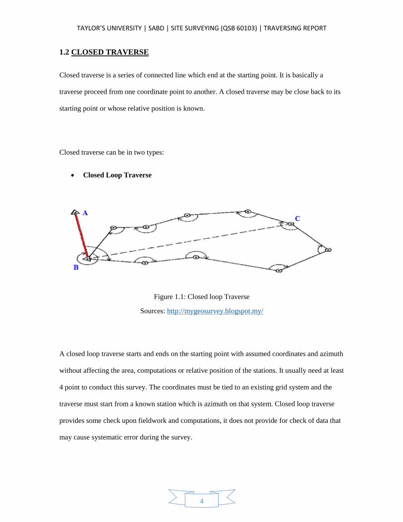
Closed Loop Traverse
Figure 1.1: Closed loop Traverse
Sources: http://mygeosurvey.blogspot.my/
A closed loop traverse starts and ends on the starting point with assumed coordinates and azimuth
without affecting the area, computations or relative position of the stations. It usually need at least
4 point to conduct this survey. The coordinates must be tied to an existing grid system and the
traverse must start from a known station which is azimuth on that system. Closed loop traverse
provides some check upon fieldwork and computations, it does not provide for check of data that
may cause systematic error during the survey.
TAYLOR’S UNIVERSITY | SABD | SITE SURVEYING (QSB 60103) | TRAVERSING REPORT
5
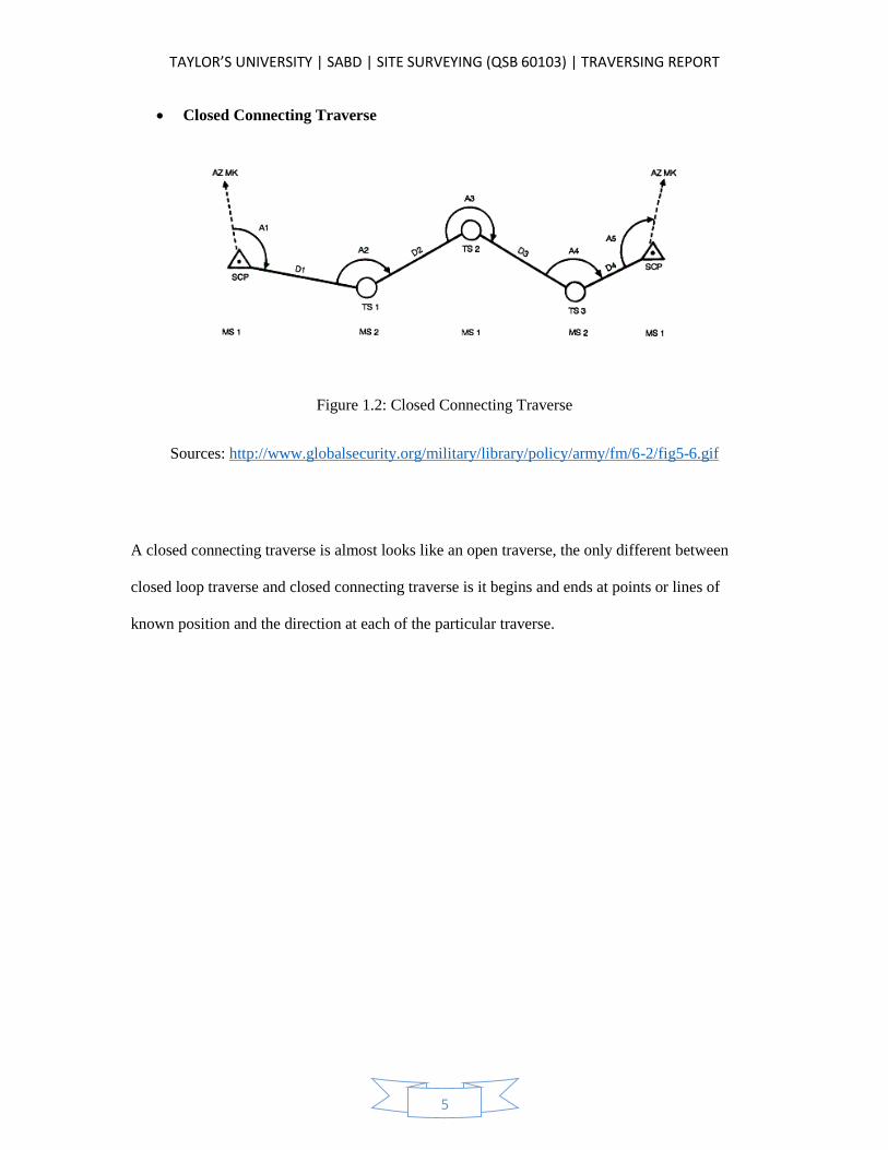
Closed Connecting Traverse
Figure 1.2: Closed Connecting Traverse
Sources: http://www.globalsecurity.org/military/library/policy/army/fm/6-2/fig5-6.gif
A closed connecting traverse is almost looks like an open traverse, the only different between
closed loop traverse and closed connecting traverse is it begins and ends at points or lines of
known position and the direction at each of the particular traverse.
TAYLOR’S UNIVERSITY | SABD | SITE SURVEYING (QSB 60103) | TRAVERSING REPORT
6
1.3 NORTHING
There are 3 reference direction or datum meridian that are used as traverse reference. Which is
Magnetic North, Grid North and True North (Geodetic North).
Magnetic North
Angle are measured from magnetic north. Since magnetic fields fluctuate over time, this
meridian is time-dependent. The magnetic fields will orientate a free swinging magnetic
needle in a north or south direction.
Grid North
A grid of lines parallel to the true meridian of one point on the grid, usually the origin of
the grid. The angle is dependent on the map projection. Since the central meridian point
to true north, when we move east or west away from the meridian, the difference between
grid north and true north will increases.
True North
True North is the direction along the earth’s surface towards to the geographic North Pole
which all the lines of longitude converge. Historically south has occasionally been used.
TAYLOR’S UNIVERSITY | SABD | SITE SURVEYING (QSB 60103) | TRAVERSING REPORT
7
1.4 AZIMUTHS
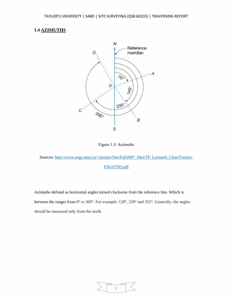
Figure 1.3: Azimuths
Sources: http://www.engr.mun.ca/~sitotaw/Site/Fall2007_files/TP_Lecture9_CloseTravers-
ENGI3703.pdf
Azimuths defined as horizontal angles turned clockwise from the reference line. Which is
between the ranges from 0° to 360°. For example: 128°, 239° and 351°. Generally, the angles
should be measured only from the north.
TAYLOR’S UNIVERSITY | SABD | SITE SURVEYING (QSB 60103) | TRAVERSING REPORT
8
1.5 BEARINGS
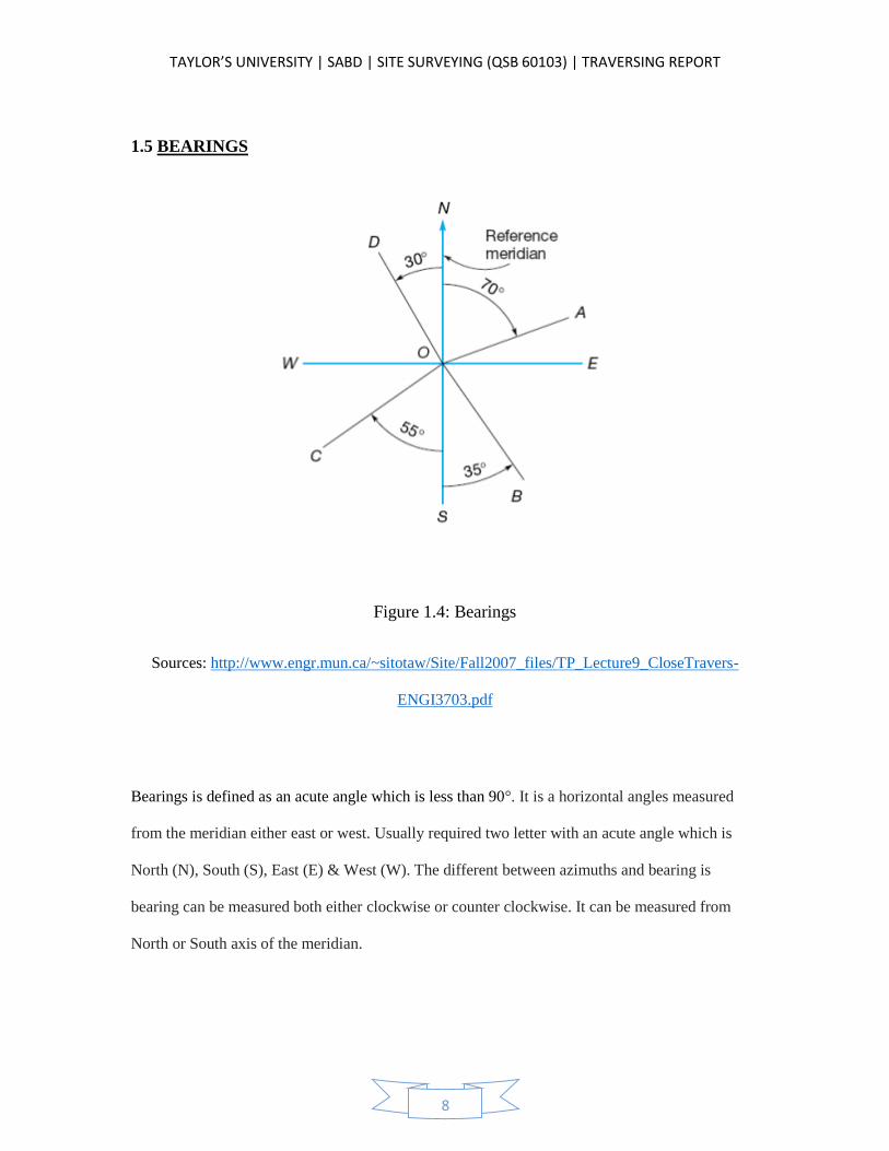
Figure 1.4: Bearings
Sources: http://www.engr.mun.ca/~sitotaw/Site/Fall2007_files/TP_Lecture9_CloseTravers-
ENGI3703.pdf
Bearings is defined as an acute angle which is less than 90°. It is a horizontal angles measured
from the meridian either east or west. Usually required two letter with an acute angle which is
North (N), South (S), East (E) & West (W). The different between azimuths and bearing is
bearing can be measured both either clockwise or counter clockwise. It can be measured from
North or South axis of the meridian.
TAYLOR’S UNIVERSITY | SABD | SITE SURVEYING (QSB 60103) | TRAVERSING REPORT
9
2.0 OBJECTIVE
To learn the principles of running a closed field traverse.
To enhance students’ knowledge in traversing procedure.
To establish ground control for photographic mapping.
To enable students to get hands-on experience in setting up and working with the
theodolites, leveling rod, tripod stand as well as other instruments and collect the data of
the relevant fieldwork.
To allow students to learn the correct method in doing traversing,
To allow students to apply the theories that had been taught in classes to a hands-on
situation.
To enable students to identify the error and make adjustment to the data by using the
correct formula.
Learn how to compute a traverse and properly adjust the measured values of a closed
traverse to achieve mathematical closure.
Determine the error of closure and compute the accuracy of work.
TAYLOR’S UNIVERSITY | SABD | SITE SURVEYING (QSB 60103) | TRAVERSING REPORT
10
3.0 OUTLINE OF APPARATUS
3.1 THEODOLITE
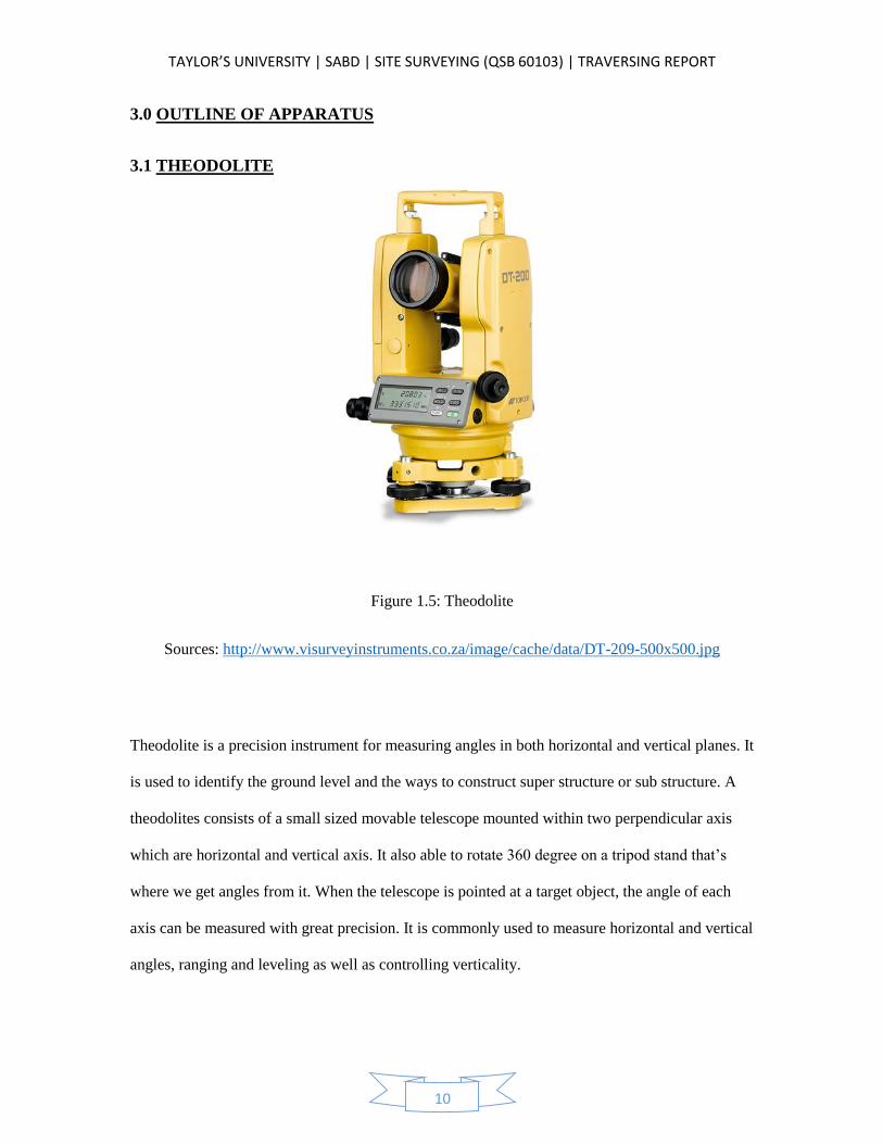
Figure 1.5: Theodolite
Sources: http://www.visurveyinstruments.co.za/image/cache/data/DT-209-500x500.jpg
Theodolite is a precision instrument for measuring angles in both horizontal and vertical planes. It
is used to identify the ground level and the ways to construct super structure or sub structure. A
theodolites consists of a small sized movable telescope mounted within two perpendicular axis
which are horizontal and vertical axis. It also able to rotate 360 degree on a tripod stand that’s
where we get angles from it. When the telescope is pointed at a target object, the angle of each
axis can be measured with great precision. It is commonly used to measure horizontal and vertical
angles, ranging and leveling as well as controlling verticality.
TAYLOR’S UNIVERSITY | SABD | SITE SURVEYING (QSB 60103) | TRAVERSING REPORT
11
3.2 TRIPOD STAND
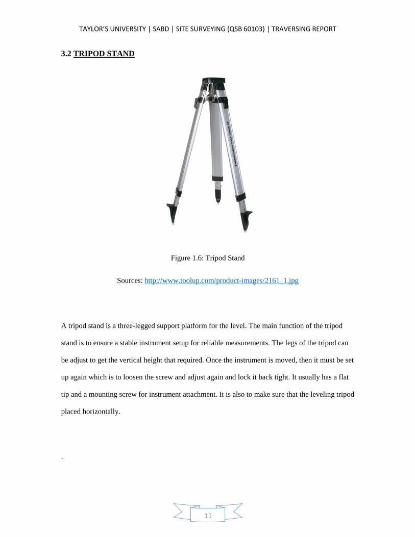
Figure 1.6: Tripod Stand
Sources: http://www.toolup.com/product-images/2161_1.jpg
A tripod stand is a three-legged support platform for the level. The main function of the tripod
stand is to ensure a stable instrument setup for reliable measurements. The legs of the tripod can
be adjust to get the vertical height that required. Once the instrument is moved, then it must be set
up again which is to loosen the screw and adjust again and lock it back tight. It usually has a flat
tip and a mounting screw for instrument attachment. It is also to make sure that the leveling tripod
placed horizontally.
.
TAYLOR’S UNIVERSITY | SABD | SITE SURVEYING (QSB 60103) | TRAVERSING REPORT
12
3.3 OPTICAL PLUMMET
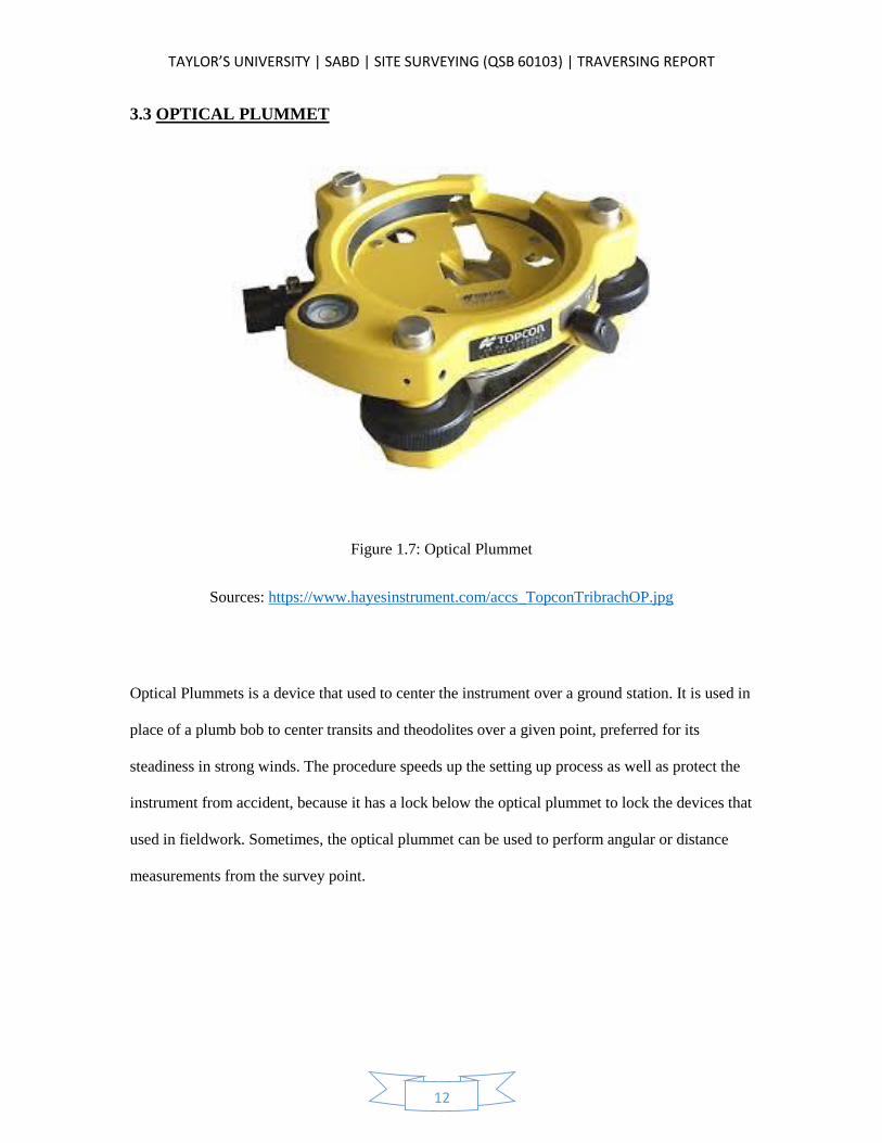
Figure 1.7: Optical Plummet
Sources: https://www.hayesinstrument.com/accs_TopconTribrachOP.jpg
Optical Plummets is a device that used to center the instrument over a ground station. It is used in
place of a plumb bob to center transits and theodolites over a given point, preferred for its
steadiness in strong winds. The procedure speeds up the setting up process as well as protect the
instrument from accident, because it has a lock below the optical plummet to lock the devices that
used in fieldwork. Sometimes, the optical plummet can be used to perform angular or distance
measurements from the survey point.
TAYLOR’S UNIVERSITY | SABD | SITE SURVEYING (QSB 60103) | TRAVERSING REPORT
13
3.4 RANGING ROD
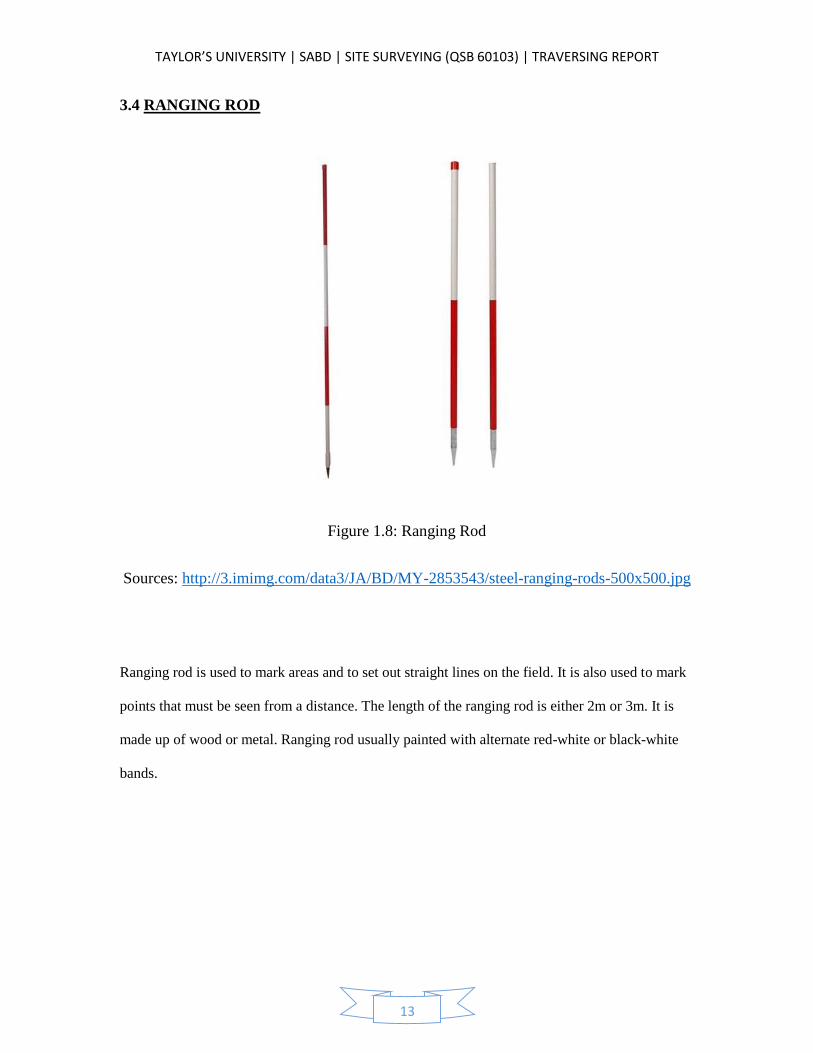
Figure 1.8: Ranging Rod
Sources: http://3.imimg.com/data3/JA/BD/MY-2853543/steel-ranging-rods-500x500.jpg
Ranging rod is used to mark areas and to set out straight lines on the field. It is also used to mark
points that must be seen from a distance. The length of the ranging rod is either 2m or 3m. It is
made up of wood or metal. Ranging rod usually painted with alternate red-white or black-white
bands.
TAYLOR’S UNIVERSITY | SABD | SITE SURVEYING (QSB 60103) | TRAVERSING REPORT
14
3.5 SPIRIT BUBBLE
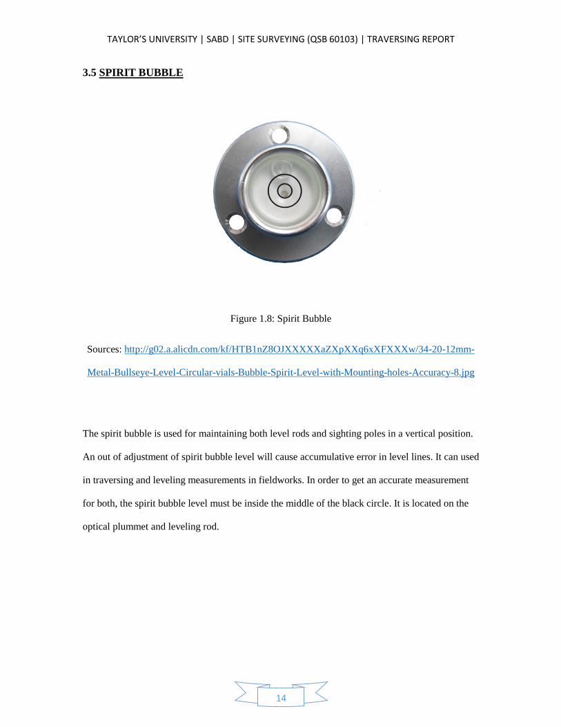
Figure 1.8: Spirit Bubble
Sources: http://g02.a.alicdn.com/kf/HTB1nZ8OJXXXXXaZXpXXq6xXFXXXw/34-20-12mm-
Metal-Bullseye-Level-Circular-vials-Bubble-Spirit-Level-with-Mounting-holes-Accuracy-8.jpg
The spirit bubble is used for maintaining both level rods and sighting poles in a vertical position.
An out of adjustment of spirit bubble level will cause accumulative error in level lines. It can used
in traversing and leveling measurements in fieldworks. In order to get an accurate measurement
for both, the spirit bubble level must be inside the middle of the black circle. It is located on the
optical plummet and leveling rod.
TAYLOR’S UNIVERSITY | SABD | SITE SURVEYING (QSB 60103) | TRAVERSING REPORT
15
3.6 PLUMB BOB
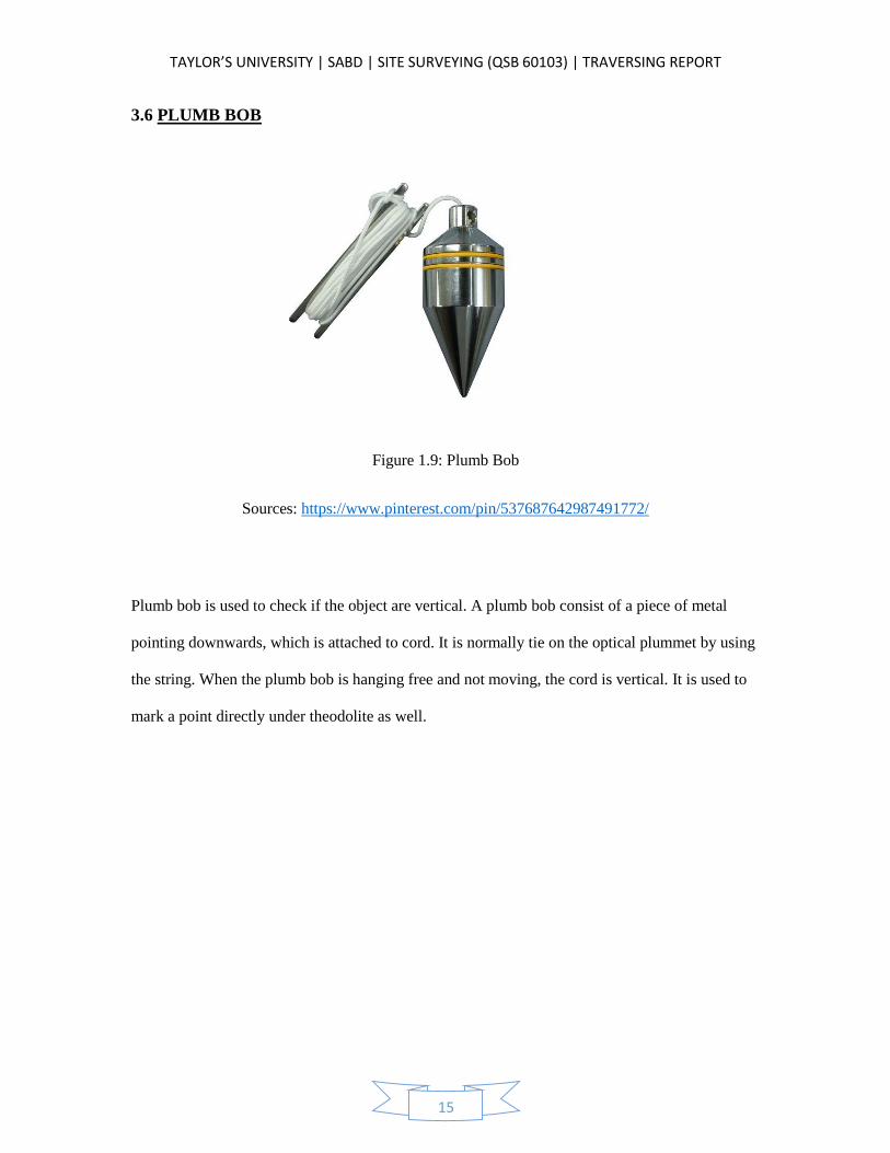
Figure 1.9: Plumb Bob
Sources: https://www.pinterest.com/pin/537687642987491772/
Plumb bob is used to check if the object are vertical. A plumb bob consist of a piece of metal
pointing downwards, which is attached to cord. It is normally tie on the optical plummet by using
the string. When the plumb bob is hanging free and not moving, the cord is vertical. It is used to
mark a point directly under theodolite as well.
TAYLOR’S UNIVERSITY | SABD | SITE SURVEYING (QSB 60103) | TRAVERSING REPORT
16
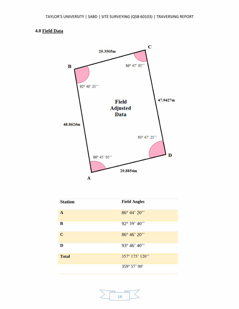
4.0 Field Data
Station Field Angles
A 86° 44’ 20’’
B 92° 39’ 40’’
C 86° 46’ 20’’
D 93° 46’ 40’’
Total 357° 175’ 120’’
359° 57’ 00’
TAYLOR’S UNIVERSITY | SABD | SITE SURVEYING (QSB 60103) | TRAVERSING REPORT
17
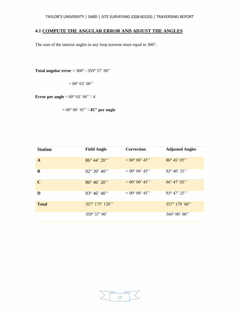
4.1 COMPUTE THE ANGULAR ERROR AND ADJUST THE ANGLES
The sum of the interior angles in any loop traverse must equal to 360°.
Total angular error = 360° - 359° 57’ 00’’
= 00° 03’ 00’’
Error per angle = 00° 03’ 00’’ / 4
= 00° 00’ 45’’ / 45’’ per angle
Station Field Angle Correction Adjusted Angles
A 86° 44’ 20’’ + 00° 00’ 45’’ 86° 45’ 05’’
B 92° 39’ 40’’ + 00° 00’ 45’’ 92° 40’ 25’’
C 86° 46’ 20’’ + 00° 00’ 45’’ 86° 47’ 05’’
D 93° 46’ 40’’ + 00° 00’ 45’’ 93° 47’ 25’’
Total 357° 175’ 120’’ 357° 179’ 60’’
359° 57’ 00’ 360° 00’ 00’’
TAYLOR’S UNIVERSITY | SABD | SITE SURVEYING (QSB 60103) | TRAVERSING REPORT
18
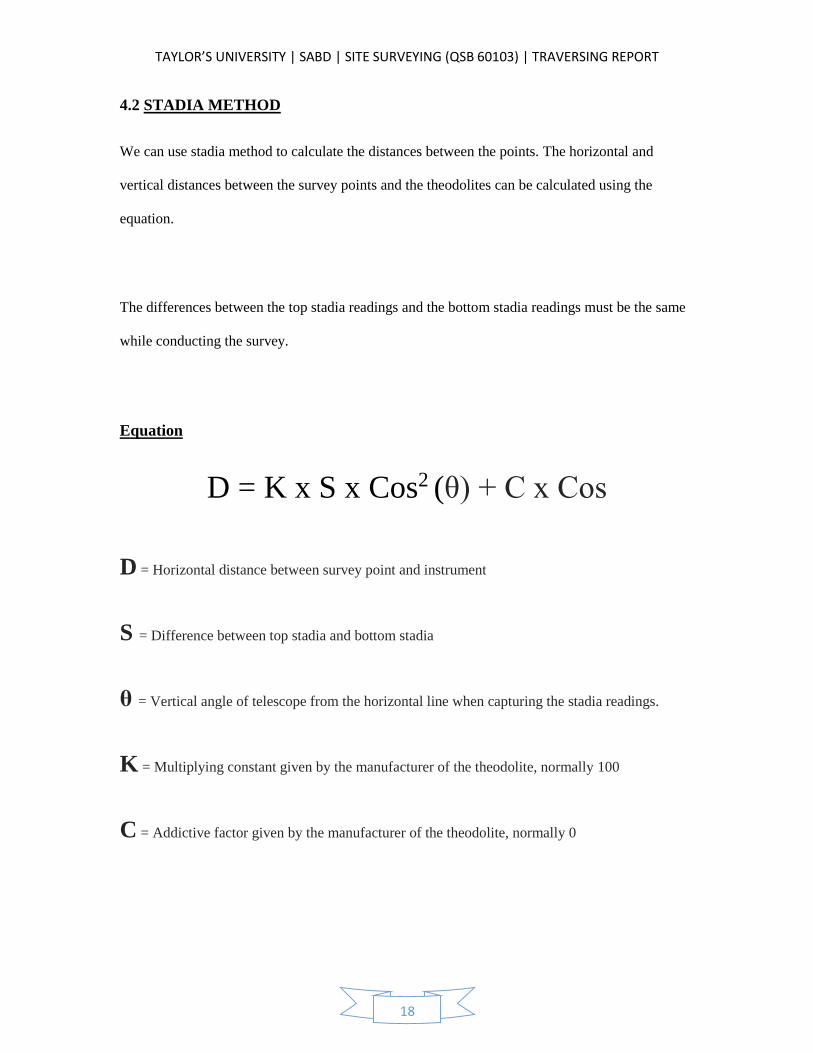
4.2 STADIA METHOD
We can use stadia method to calculate the distances between the points. The horizontal and
vertical distances between the survey points and the theodolites can be calculated using the
equation.
The differences between the top stadia readings and the bottom stadia readings must be the same
while conducting the survey.
Equation
D = K x S x Cos2 (θ) + C x Cos
D = Horizontal distance between survey point and instrument
S = Difference between top stadia and bottom stadia
θ = Vertical angle of telescope from the horizontal line when capturing the stadia readings.
K = Multiplying constant given by the manufacturer of the theodolite, normally 100
C = Addictive factor given by the manufacturer of the theodolite, normally 0
TAYLOR’S UNIVERSITY | SABD | SITE SURVEYING (QSB 60103) | TRAVERSING REPORT
19
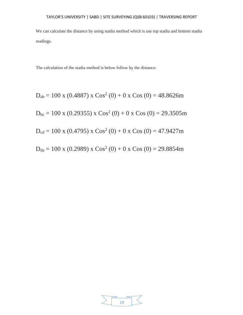
We can calculate the distance by using stadia method which is use top stadia and bottom stadia
readings.
The calculation of the stadia method is below follow by the distance:
Dab = 100 x (0.4887) x Cos2 (0) + 0 x Cos (0) = 48.8626m
Dbc = 100 x (0.29355) x Cos2 (0) + 0 x Cos (0) = 29.3505m
Dcd = 100 x (0.4795) x Cos2 (0) + 0 x Cos (0) = 47.9427m
Dda = 100 x (0.2989) x Cos2 (0) + 0 x Cos (0) = 29.8854m
TAYLOR’S UNIVERSITY | SABD | SITE SURVEYING (QSB 60103) | TRAVERSING REPORT
20
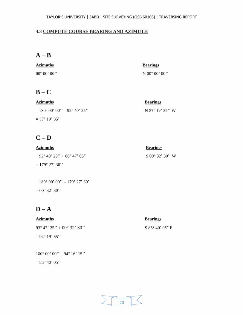
4.3 COMPUTE COURSE BEARING AND AZIMUTH
A – B
Azimuths Bearings
00° 00’ 00’’ N 00° 00’ 00’’
B – C
Azimuths Bearings
180° 00’ 00’’ – 92° 40’ 25’’ N 87° 19’ 35’’ W
= 87° 19’ 35’’
C – D
Azimuths Bearings
92° 40’ 25’’ + 86° 47’ 05’’ S 00° 32’ 30’’ W
= 179° 27’ 30’’
180° 00’ 00’’ – 179° 27’ 30’’
= 00° 32’ 30’’
D – A
Azimuths Bearings
93° 47’ 25’’ + 00° 32’ 30’’ S 85° 40’ 05’’E
= 94° 19’ 55’’
180° 00’ 00’’ – 94° 16’ 15’’
= 85° 40’ 05’’
TAYLOR’S UNIVERSITY | SABD | SITE SURVEYING (QSB 60103) | TRAVERSING REPORT
21
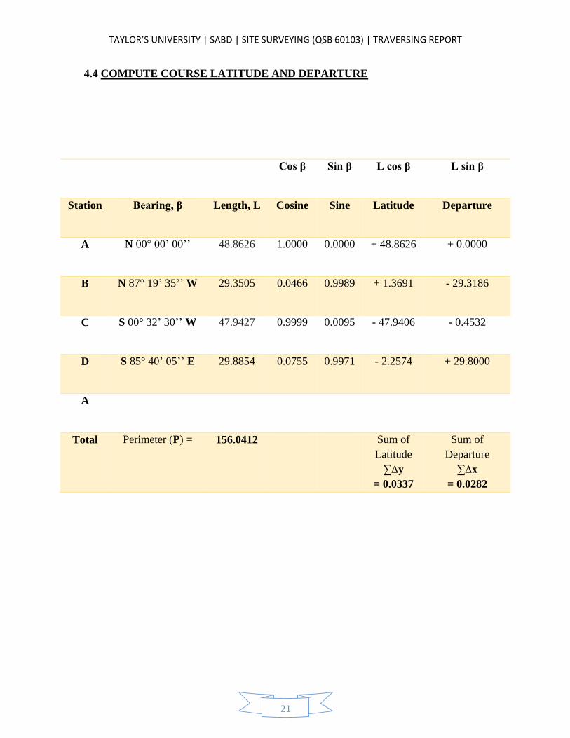
4.4 COMPUTE COURSE LATITUDE AND DEPARTURE
Cos β Sin β L cos β L sin β
Station Bearing, β Length, L Cosine Sine Latitude Departure
A N 00° 00’ 00’’ 48.8626 1.0000 0.0000 + 48.8626 + 0.0000
B N 87° 19’ 35’’ W 29.3505 0.0466 0.9989 + 1.3691 - 29.3186
C S 00° 32’ 30’’ W 47.9427 0.9999 0.0095 - 47.9406 - 0.4532
D S 85° 40’ 05’’ E 29.8854 0.0755 0.9971 - 2.2574 + 29.8000
A
Total Perimeter (P) = 156.0412 Sum of
Latitude
∑∆y
= 0.0337
Sum of
Departure
∑∆x
= 0.0282
TAYLOR’S UNIVERSITY | SABD | SITE SURVEYING (QSB 60103) | TRAVERSING REPORT
22
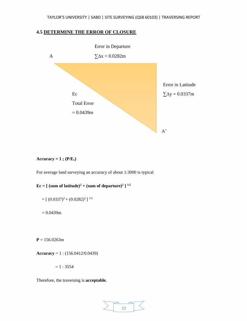
4.5 DETERMINE THE ERROR OF CLOSURE
Error in Departure
A ∑∆x = 0.0282m
Error in Latitude
Ec ∑∆y = 0.0337m
Total Error
= 0.0439m
A’
Accuracy = 1 ; (P/Ec)
For average land surveying an accuracy of about 1:3000 is typical
Ec = [ (sum of latitude)2 + (sum of departure)2 ] 1/2
= [ (0.0337)2 + (0.0282)2 ] 1/2
= 0.0439m
P = 156.0263m
Accuracy = 1 : (156.0412/0.0439)
= 1 : 3554
Therefore, the traversing is acceptable.
TAYLOR’S UNIVERSITY | SABD | SITE SURVEYING (QSB 60103) | TRAVERSING REPORT
23
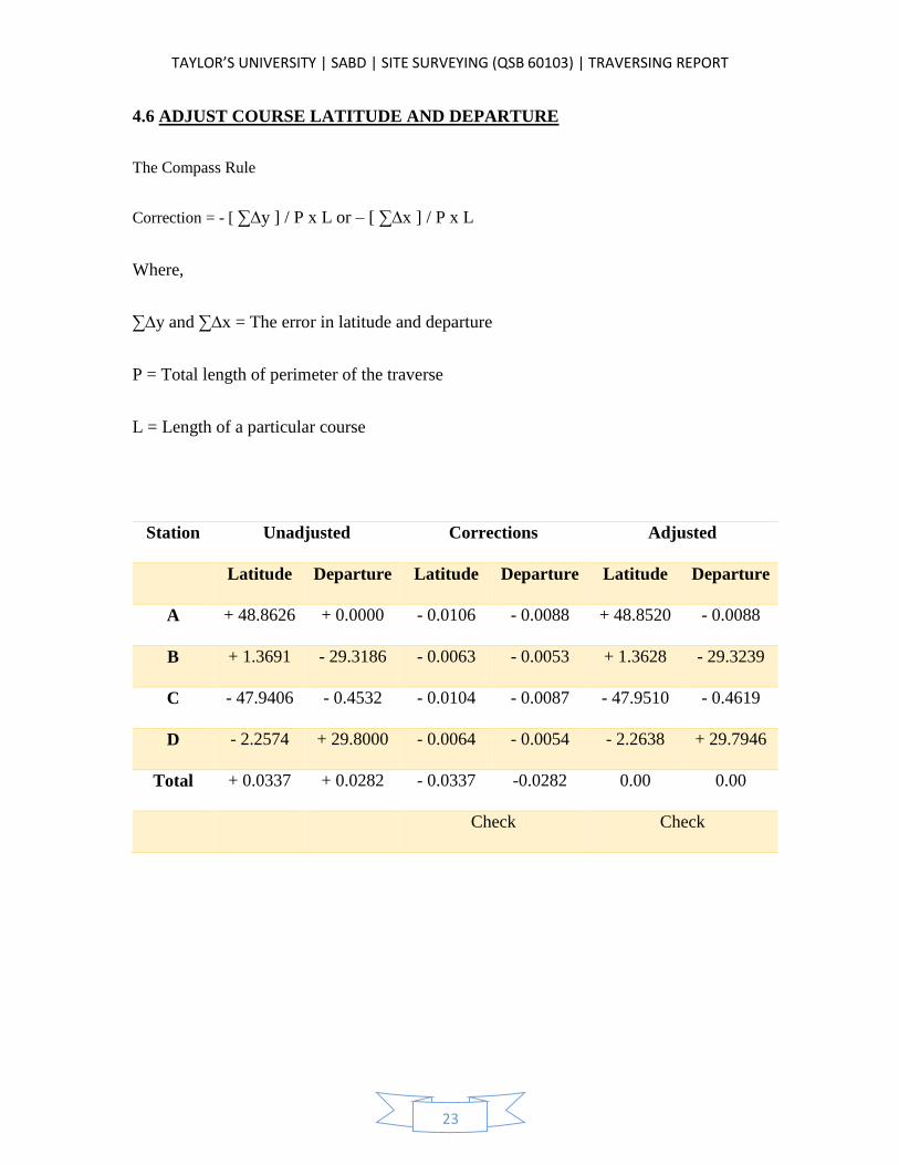
4.6 ADJUST COURSE LATITUDE AND DEPARTURE
The Compass Rule
Correction = - [ ∑∆y ] / P x L or – [ ∑∆x ] / P x L
Where,
∑∆y and ∑∆x = The error in latitude and departure
P = Total length of perimeter of the traverse
L = Length of a particular course
Station Unadjusted Corrections Adjusted
Latitude Departure Latitude Departure Latitude Departure
A + 48.8626 + 0.0000 - 0.0106 - 0.0088 + 48.8520 - 0.0088
B + 1.3691 - 29.3186 - 0.0063 - 0.0053 + 1.3628 - 29.3239
C - 47.9406 - 0.4532 - 0.0104 - 0.0087 - 47.9510 - 0.4619
D - 2.2574 + 29.8000 - 0.0064 - 0.0054 - 2.2638 + 29.7946
Total + 0.0337 + 0.0282 - 0.0337 -0.0282 0.00 0.00
Check Check
TAYLOR’S UNIVERSITY | SABD | SITE SURVEYING (QSB 60103) | TRAVERSING REPORT
24
5.0 DISCUSSION
From this fieldwork, we learnt to conduct a traverse survey by using a theodolite and
several formulas that we learnt during traversing class. Throughout this survey, we can be able to
applied the technique and knowledge thought by our lecturer, Mr. Chai.
From this survey, we know that point A, B, C and D are laid out on the site respectively.
The theodolite will be placed on point A which is our starting point and started to conduct our
survey. The angles that we get from the theodolite must be read from left to the right in order to
obtain a more accurate reading.
The zero angle will be set on point A as well and turned the theodolite to point D and
measure to get the stadia reading as well as the horizontal and vertical angles. After we get the all
the readings and the angles from one point, we switch the theodolite to another point and repeat
the same procedure again to get another point of readings.
What we found out that was really hard for us is we couldn’t get the spirit bubble into the
black circle. But after Mr. Chai had taught us, finally we can measure ourselves very fast and
accurately.
At the end of the process, the total angles must be 360°. However, in our report from the
table of the field data, the total angle was 357° 57’ 00’’. Thus, we knew that there was a
misclosure error occurred as there is a difference of 3’ 00’’. Means in every angle we measured,
there is a 45’’ of error. Therefore, we used the trigonometry traversing calculation technique to
solve it.
Lastly, at the end, we found that the latitude and departure also have a minor error of
0.0337 (Latitude) and 0.0282 (Departure). We solved it by using the compass rule. After compile
everything, the report is finally done.
TAYLOR’S UNIVERSITY | SABD | SITE SURVEYING (QSB 60103) | TRAVERSING REPORT
25
6.0 CONCLUSION
In conclusion, this is our second fieldwork which is traversing. In this fieldwork, we were
required to carry out a closed loop traverse survey that is located at the car park. A special
characteristic of a closed loop traverse is it starts and ends at the same point, forming a closed
geometric figure called a polygon. My fellow group mates and I conduct the survey together at
the car park. Two of them is holding the leveling staff, one of a group mate is recording down the
data while one of the group member is taking the readings for the traverse survey.
As we taught in class that the horizontal reading must be taken twice which is the first
reading is taken, then turn back again to take the second reading. We also did recorded the top
stadia, middle stadia and bottom stadia readings to calculate the length of the perimeter of the
traverse since we didn’t have a measuring tape.
The angles are usually obtained through the usage of equipment provided by our lecturer.
However, we were unable to obtain the exact reading of 360°, therefore, some adjustment was
made in order to achieve 360° in our traverse survey completely.
Although the formula was really hard for us to understand and apply compare to leveling,
but we try hard to learning with a spirit of not giving up. We really do likes site surveying
because we can actually feel that we are working together.
In a nutshell, we thanks our lecturer Mr. Chai for giving us an opportunities to learn and
hands on in leveling. We hope that next time we can have a chance to conduct a survey like this
again.