Site Surveying Traversing
16
1 | Page SCHOOL OF ARCHITECTURE, BUILDING AND DESIGN BACHELOR OF QUANTITY SURVEYING (HONOURS) QSB 60103- SITE SURVEYING Fieldwork 2 Report Traversing Name Student ID Marks LEE KIM THIAM 0310710 LEE CHUN YEE 0321748 LEE PEI GIE 0315653 LEE KIT HUNG 0315722
-
Upload
darren-lee -
Category
Education
-
view
93 -
download
0
Transcript of Site Surveying Traversing
1 | P a g e
SCHOOL OF ARCHITECTURE, BUILDING AND DESIGN
BACHELOR OF QUANTITY SURVEYING (HONOURS)
QSB 60103- SITE SURVEYING
Fieldwork 2 Report
Traversing
Name Student ID Marks
LEE KIM THIAM
0310710
LEE CHUN YEE
0321748
LEE PEI GIE
0315653
LEE KIT HUNG
0315722
2 | P a g e
Table of Content
Content Page
Cover Page 1
Table of Content 2
A. Introduction 3 - 5
B. Outline of Apparatus 6 - 7
i) Theodolite 6
ii) Adjustable Leg-Tripod 6
iii) Plumb Bob 6
iv) Ranging Rod 7
v) Measuring Tape 7
C. Objectives 8
D. Field Data 9 - 15
E. Conclusion 16
3 | P a g e
A. Introduction
Traversing is the most common type of control survey. In engineering work, it is
used to locate topographic detail for preparation of plan, locate engineering works
and process and order earthwork. A traverse consists of an interconnected series of
lines called courses, running between a series of points on the ground called
traverse stations. Therefore, a traverse also known as a series of established station
tied together by angle and distances.
The accuracy of traverses is dependable to the instruments or equipment and
measuring techniques. For first class traverse, the maximum misclosure or allowable
misclosure is 1’15” and the fractional error is 1:8000. However, for second class
traverse, the maximum misclosure is 2’30” and the fractional linear error is 1:4000.
The control traverse we conducting should be a first class traverse.
4 | P a g e
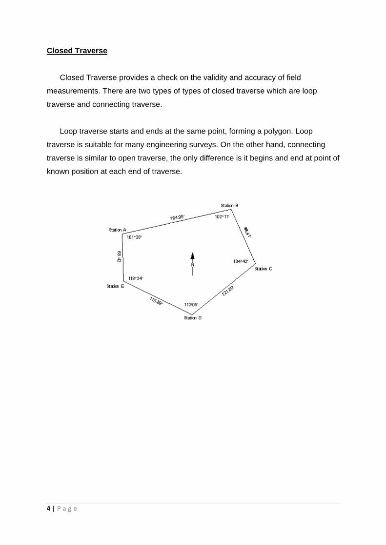
Closed Traverse
Closed Traverse provides a check on the validity and accuracy of field
measurements. There are two types of types of closed traverse which are loop
traverse and connecting traverse.
Loop traverse starts and ends at the same point, forming a polygon. Loop
traverse is suitable for many engineering surveys. On the other hand, connecting
traverse is similar to open traverse, the only difference is it begins and end at point of
known position at each end of traverse.
5 | P a g e
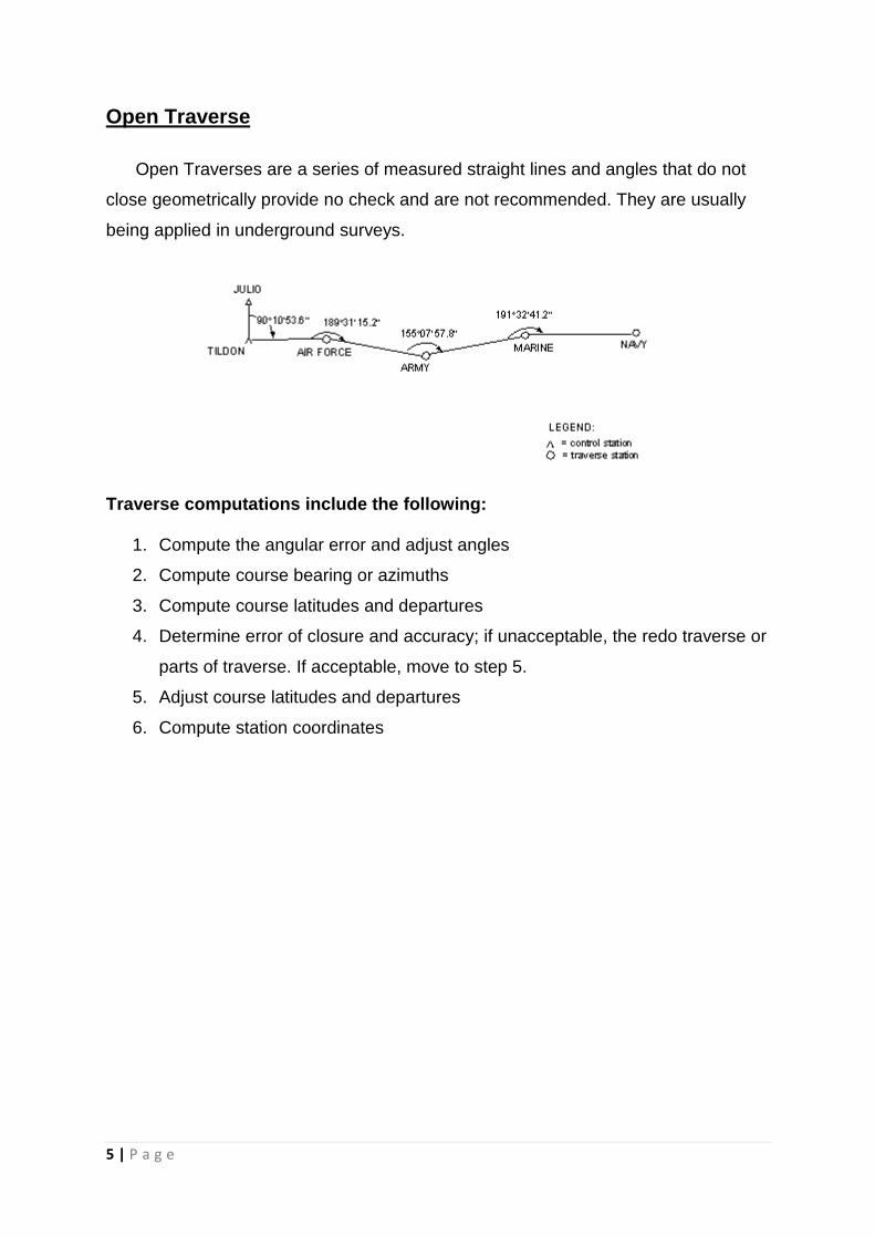
Open Traverse
Open Traverses are a series of measured straight lines and angles that do not
close geometrically provide no check and are not recommended. They are usually
being applied in underground surveys.
Traverse computations include the following:
1. Compute the angular error and adjust angles
2. Compute course bearing or azimuths
3. Compute course latitudes and departures
4. Determine error of closure and accuracy; if unacceptable, the redo traverse or
parts of traverse. If acceptable, move to step 5.
5. Adjust course latitudes and departures
6. Compute station coordinates
6 | P a g e
B. Outline of Apparatus
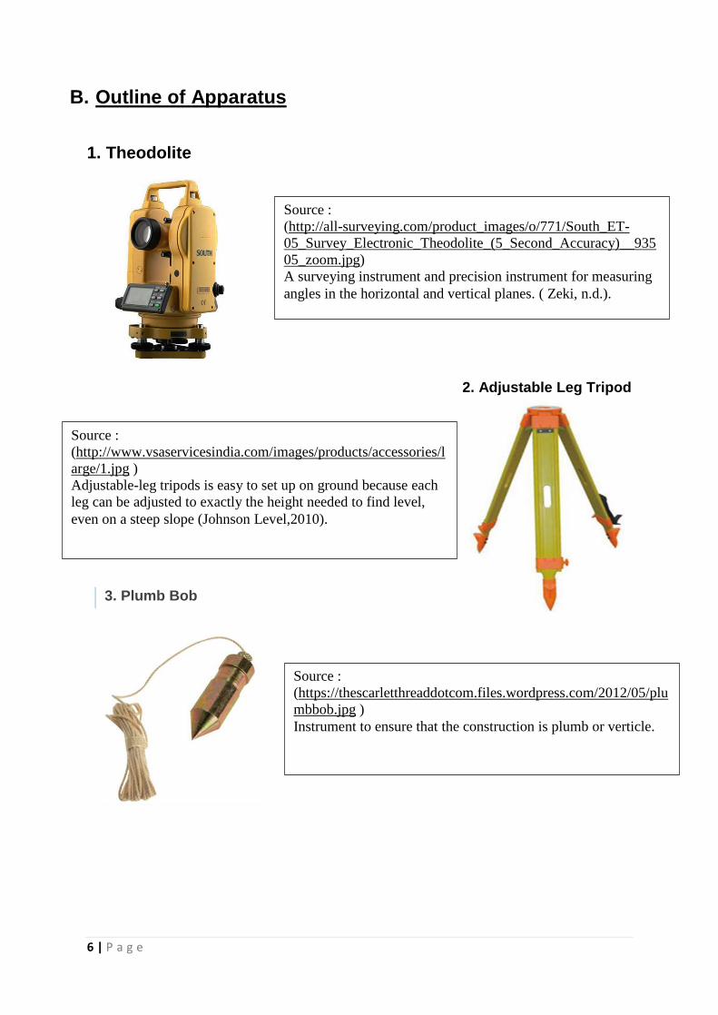
1. Theodolite
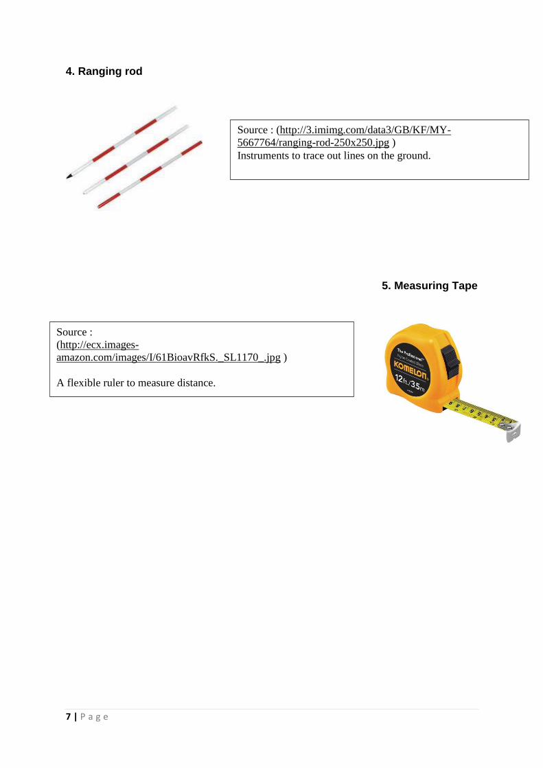
2. Adjustable Leg Tripod
Source :
(http://all-surveying.com/product_images/o/771/South_ET-
05_Survey_Electronic_Theodolite_(5_Second_Accuracy)__935
05_zoom.jpg)
A surveying instrument and precision instrument for measuring
angles in the horizontal and vertical planes. ( Zeki, n.d.).
Source :
(http://www.vsaservicesindia.com/images/products/accessories/l
arge/1.jpg )
Adjustable-leg tripods is easy to set up on ground because each
leg can be adjusted to exactly the height needed to find level,
even on a steep slope (Johnson Level,2010).
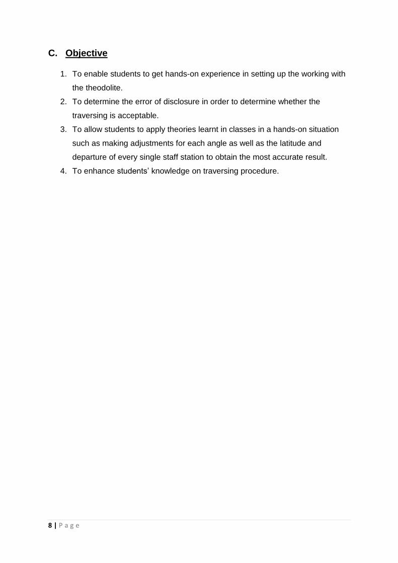
Source :
(https://thescarletthreaddotcom.files.wordpress.com/2012/05/plu
mbbob.jpg )
Instrument to ensure that the construction is plumb or verticle.
3. Plumb Bob
7 | P a g e
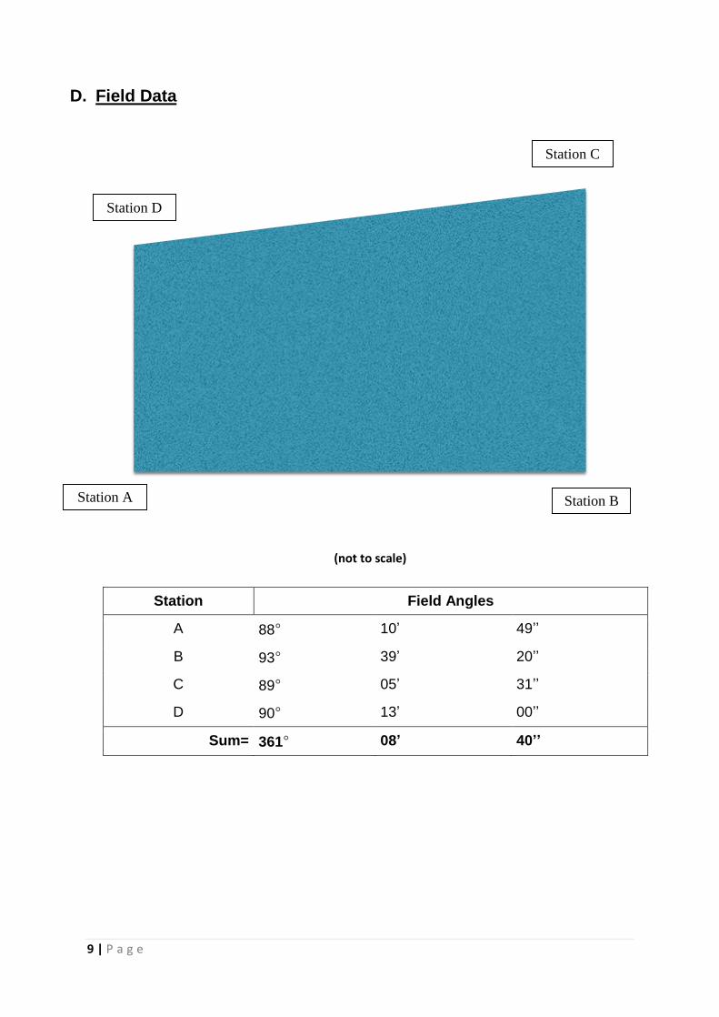
4. Ranging rod
5. Measuring Tape
Source : (http://3.imimg.com/data3/GB/KF/MY-
5667764/ranging-rod-250x250.jpg )
Instruments to trace out lines on the ground.
Source :
(http://ecx.images-
amazon.com/images/I/61BioavRfkS._SL1170_.jpg )
A flexible ruler to measure distance.
8 | P a g e
C. Objective
1. To enable students to get hands-on experience in setting up the working with
the theodolite.
2. To determine the error of disclosure in order to determine whether the
traversing is acceptable.
3. To allow students to apply theories learnt in classes in a hands-on situation
such as making adjustments for each angle as well as the latitude and
departure of every single staff station to obtain the most accurate result.
4. To enhance students’ knowledge on traversing procedure.
9 | P a g e
D. Field Data
Station Field Angles
A 88° 10’ 49’’
B 93° 39’ 20’’
C 89° 05’ 31’’
D 90° 13’ 00’’
Sum= 361° 08’ 40’’
(not to scale)
Station D
Station A
Station C
Station B
10 | P a g e
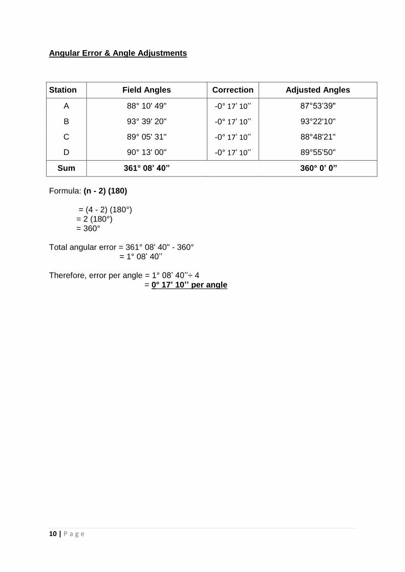
Angular Error & Angle Adjustments
Formula: (n - 2) (180) = (4 - 2) (180°) = 2 (180°) = 360° Total angular error = 361° 08' 40" - 360° = 1° 08’ 40’’ Therefore, error per angle = 1° 08’ 40’’÷ 4 = 0° 17’ 10’’ per angle
Station Field Angles Correction Adjusted Angles
A 88° 10' 49" -0° 17’ 10’’ 87°53’39"
B 93° 39' 20" -0° 17’ 10’’ 93°22'10"
C 89° 05' 31" -0° 17’ 10’’ 88°48'21"
D 90° 13' 00" -0° 17’ 10’’ 89°55'50"
Sum 361° 08’ 40” 360° 0’ 0”
11 | P a g e
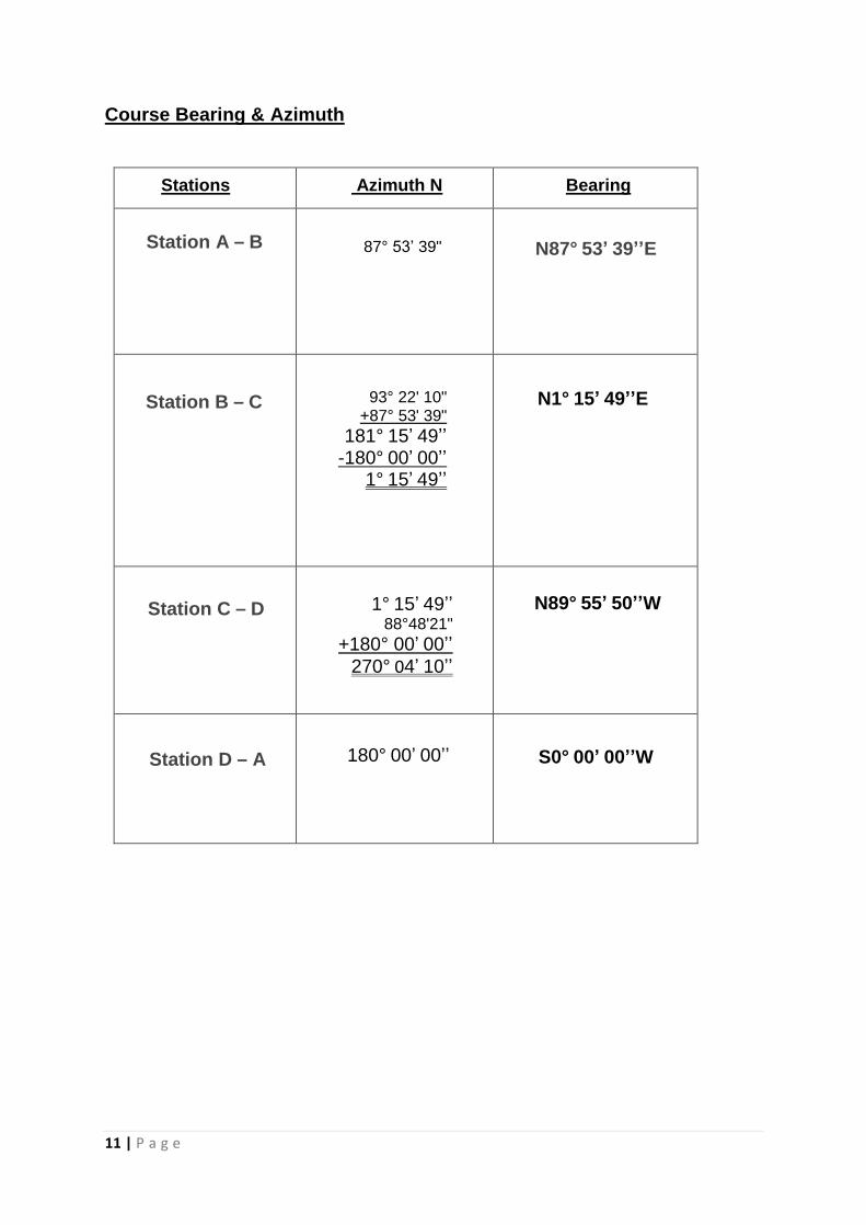
Course Bearing & Azimuth
Station A – B
S0° 00’ 00’’W 180° 00’ 00’’
N89° 55’ 50’’W 1° 15’ 49’’ 88°48'21"
+180° 00’ 00’’
270° 04’ 10’’
93° 22' 10" +87° 53' 39"
181° 15’ 49’’ -180° 00’ 00’’
1° 15’ 49’’
N1° 15’ 49’’E
Stations Azimuth N Bearing
87° 53’ 39"
90° 09’ 00’’ -93° 14’ 50’’
3° 14’ 50’’ -
N87° 53’ 39’’E
Station B – C
Station C – D
Station D – A
12 | P a g e
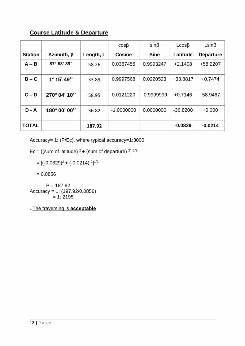
Course Latitude & Departure
Accuracy= 1: (P/Ec), where typical accuracy=1:3000 Ec = [(sum of latitude) 2 + (sum of departure) 2] 1/2
= [(-0.0829)2 + (-0.0214) 2]1/2
= 0.0856 P = 187.92 Accuracy = 1: (197.92/0.0856) = 1: 2195
∴The traversing is acceptable
cosβ sinβ Lcosβ Lsinβ
Station Azimuth, β Length, L Cosine Sine Latitude Departure
A – B 87° 53’ 39"
58.26 0.0367455 0.9993247 +2.1408 +58.2207
B – C 1° 15’ 49’’
33.89 0.9997568 0.0220523 +33.8817 +0.7474
C – D 270° 04’ 10’’
58.95 0.0121220 -0.9999999 +0.7146 -58.9467
D - A 180° 00’ 00’’
36.82 -1.0000000 0.0000000 -36.8200 +0.000
TOTAL 187.92 -0.0829 -0.0214
13 | P a g e
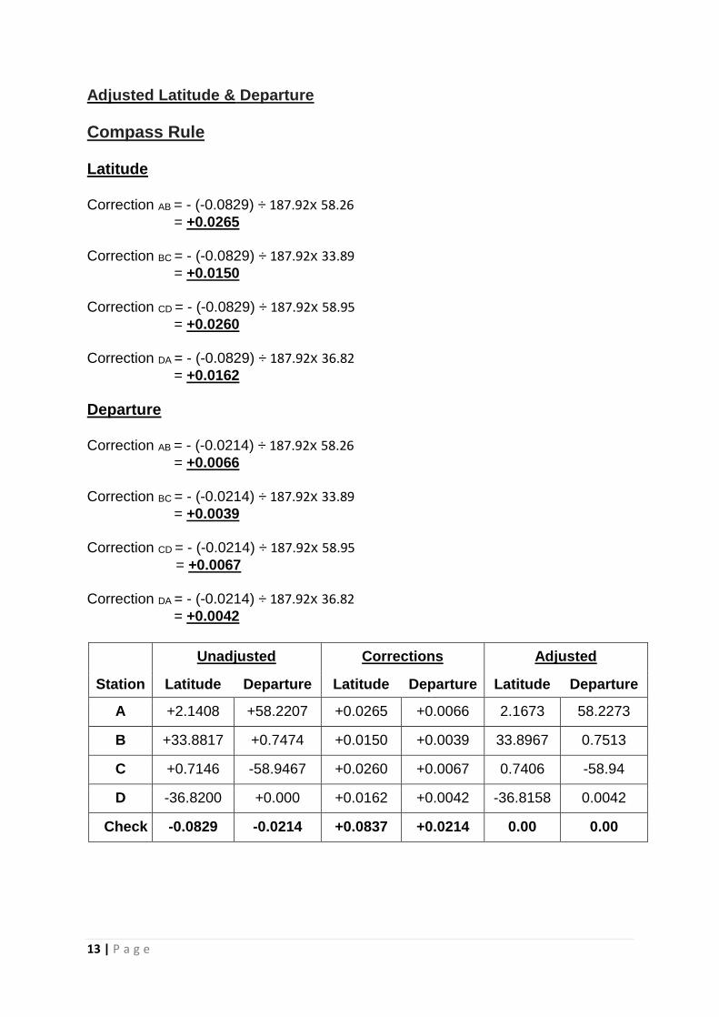
Adjusted Latitude & Departure
Compass Rule
Latitude Correction AB = - (-0.0829) ÷ 187.92x 58.26
= +0.0265
Correction BC = - (-0.0829) ÷ 187.92x 33.89
= +0.0150
Correction CD = - (-0.0829) ÷ 187.92x 58.95
= +0.0260
Correction DA = - (-0.0829) ÷ 187.92x 36.82
= +0.0162
Departure Correction AB = - (-0.0214) ÷ 187.92x 58.26
= +0.0066
Correction BC = - (-0.0214) ÷ 187.92x 33.89
= +0.0039
Correction CD = - (-0.0214) ÷ 187.92x 58.95
= +0.0067
Correction DA = - (-0.0214) ÷ 187.92x 36.82
= +0.0042
Unadjusted Corrections Adjusted
Station Latitude Departure Latitude Departure Latitude Departure
A +2.1408 +58.2207 +0.0265 +0.0066 2.1673 58.2273
B +33.8817 +0.7474 +0.0150 +0.0039 33.8967 0.7513
C +0.7146 -58.9467 +0.0260 +0.0067 0.7406 -58.94
D -36.8200 +0.000 +0.0162 +0.0042 -36.8158 0.0042
Check -0.0829 -0.0214 +0.0837 +0.0214 0.00 0.00
14 | P a g e
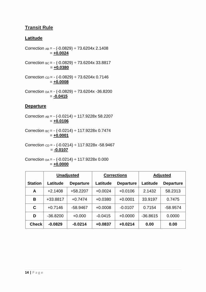
Transit Rule Latitude Correction AB = - (-0.0829) ÷ 73.6204x 2.1408 = +0.0024 Correction BC = - (-0.0829) ÷ 73.6204x 33.8817 = +0.0380 Correction CD = - (-0.0829) ÷ 73.6204x 0.7146 = +0.0008 Correction DA = - (-0.0829) ÷ 73.6204x -36.8200 = -0.0415
Departure Correction AB = - (-0.0214) ÷ 117.9228x 58.2207
= +0.0106 Correction BC = - (-0.0214) ÷ 117.9228x 0.7474
= +0.0001 Correction CD = - (-0.0214) ÷ 117.9228x -58.9467 = -0.0107 Correction DA = - (-0.0214) ÷ 117.9228x 0.000
= +0.0000
Unadjusted Corrections Adjusted
Station Latitude Departure Latitude Departure Latitude Departure
A +2.1408 +58.2207 +0.0024 +0.0106 2.1432 58.2313
B +33.8817 +0.7474 +0.0380 +0.0001 33.9197 0.7475
C +0.7146 -58.9467 +0.0008 -0.0107 0.7154 -58.9574
D -36.8200 +0.000 -0.0415 +0.0000 -36.8615 0.0000
Check -0.0829 -0.0214 +0.0837 +0.0214 0.00 0.00
15 | P a g e
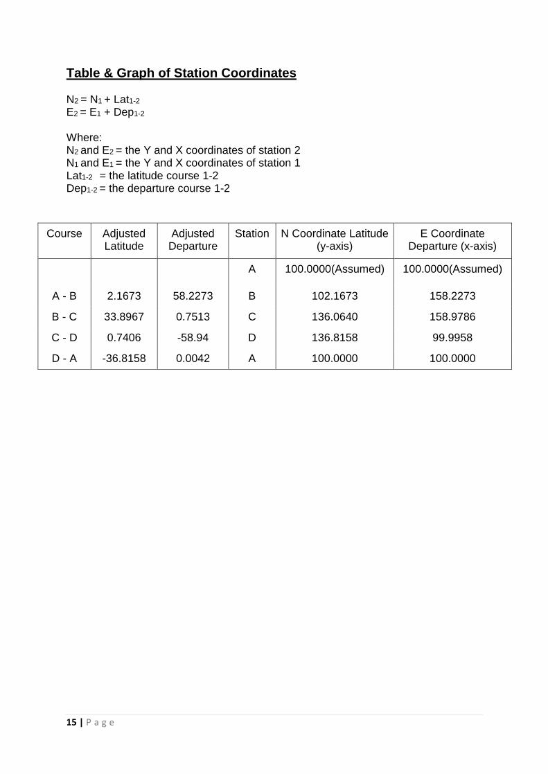
Table & Graph of Station Coordinates N2 = N1 + Lat1-2
E2 = E1 + Dep1-2
Where: N2 and E2 = the Y and X coordinates of station 2 N1 and E1 = the Y and X coordinates of station 1 Lat1-2 = the latitude course 1-2 Dep1-2 = the departure course 1-2
Course Adjusted Latitude
Adjusted Departure
Station N Coordinate Latitude (y-axis)
E Coordinate Departure (x-axis)
A 100.0000(Assumed) 100.0000(Assumed)
A - B 2.1673 58.2273 B 102.1673 158.2273
B - C 33.8967 0.7513 C 136.0640 158.9786
C - D 0.7406 -58.94 D 136.8158 99.9958
D - A -36.8158 0.0042 A 100.0000 100.0000
16 | P a g e
E. Conclusion
In this fieldwork, the type of traverse used is the closed-loop traverse. We used
the number of steps from one of our group members to measure the length of each
course. From there, we converted the steps into meters.
Our error in latitude is -0.0829 while our error in latitude is -0.0214. The total
error is 0.0856. Using the formula for accuracy:
Accuracy = 1: Perimeter/ Error Closure
We obtained an accuracy of 1: 2195.
Since the average land surveying acquires the typical accuracy of 1:3000, our
traverse survey is acceptable.
For the adjustment of latitude and departure, we used the compass rule and
transit rule.
Throughout the entire process of this traversing assignment, we have managed to
determine the approximate angles of a courses between different points at the
specific lengths.