Transportation Infrastructure Asset Monitoring through the ...
106
Transportation Infrastructure Asset Monitoring through the Industrial Internet-of-Things October 2020 Final Report Project number TR20206 MoDOT Research Report number cmr 20-011 PREPARED BY: Ronaldo Luna JC Murray Jim Hummert AECOM Technical Services, Inc. PREPARED FOR: Missouri Department of Transportation Construction and Materials Division, Research Section
Transcript of Transportation Infrastructure Asset Monitoring through the ...

Transportation Infrastructure Asset Monitoring through the Industrial Internet-of-Things
October 2020 Final Report
Project number TR20206 MoDOT Research Report number cmr 20-011
PREPARED BY:
Ronaldo Luna
JC Murray
Jim Hummert
AECOM Technical Services, Inc.
PREPARED FOR:
Missouri Department of Transportation
Construction and Materials Division, Research Section

TECHNICAL REPORT DOCUMENTATION PAGE 1. Report No.cmr 20-011
2. Government Accession No. 3. Recipient’s Catalog No.
4. Title and SubtitleTransportation Infrastructure Asset Monitoring through the Industrial Internet-of-Things
5. Report DateJuly 2020Published: October 20206. Performing Organization Code
7. Author(s)Ronaldo LunaJC MurrayJim Hummert
8. Performing Organization Report No.
9. Performing Organization Name and AddressAECOM Technical Services, Inc.100 N. BroadwaySt. Louis, MO 63102
10. Work Unit No.
11. Contract or Grant No.MoDOT project #TR202006
12. Sponsoring Agency Name and AddressMissouri Department of Transportation (SPR-B)Construction and Materials DivisionP.O. Box 270Jefferson City, MO 65102
13. Type of Report and Period CoveredFinal Report (October 1, 2019-July 31,2020)
14. Sponsoring Agency Code
15. Supplementary NotesConducted in cooperation with the U.S. Department of Transportation, Federal Highway Administration. MoDOT research reportsare available in the Innovation Library at https://www.modot.org/research-publications.
16. AbstractThe Internet-of-Things (IoT) is a technology that has been growing since its inception in 2009 and as wireless technology becomesmore ubiquitous, so are its applications. Even though this technology started with consumer applications, it has entered manyindustrial applications in factories, utilities, and smart cities. Recently these applications are being referred as the IndustrialInternet of Things (IIoT). The research goal of this study is to explore the current status and viability of the IIoT technology for thepurpose of asset management of transportation infrastructure or the actual built infrastructure distributed along the highway systemin the state of Missouri. This research project was framed by MoDOT in two phases. Phase 1 focus was on preliminary research toassess the readiness of IIoT for initial implementation on the transportation highway system (such as bridges, pavements, retainingwalls, signs, etc.). Phase 2 will implement a pilot study on a limited number of structures to physically evaluate the technology.This report is the result of Phase 1, which summarizes the findings during this period.
17. Key WordsAsset management; Highway departments; Infrastructure;Monitoring; Structural health monitoring; Transportation planning
18. Distribution StatementNo restrictions. This document is available through theNational Technical Information Service, Springfield, VA22161.
19. Security Classif. (of this report)Unclassified.
20. Security Classif. (of thispage)Unclassified.
21. No. of Pages 106
22. Price
Form DOT F 1700.7 (8-72) Reproduction of completed page authorized
TRANSPORTATION INFRASTRUCTURE ASSET
MONITORING THROUGH THE INDUSTRIAL INTERNET-OF-THINGS
Final Report July 2020
Ronaldo Luna, JC Murray, and Jim Hummert
Prepared for the
Missouri Department of Transportation
A report from AECOM Technical Services, Inc.

iii
COPYRIGHT PERMISSIONS The authors herein are responsible for the authenticity of their materials and for obtaining written permissions from publishers or individuals who own the copyright to any previously published or copyrighted material used herein.
DISCLAIMER The opinions, findings, and conclusions expressed in this document are those of the investigators. They are not necessarily those of the Missouri Department of Transportation, U.S. Department of Transportation, or Federal Highway Administration. This information does not constitute a standard or specification.
iv
Table of Contents
Executive Summary ..................................................................................................................... viii 1. Introduction ............................................................................................................................. 1
1.1. Project Aim (Goals) ........................................................................................................ 1 1.2. Research Objectives ........................................................................................................ 1
2. Background ............................................................................................................................. 3 2.1. Historical Origins of IoT and IIoT .................................................................................. 3 2.2. Industrial Applications .................................................................................................... 4 2.3. How it Works: Definitions and Nomenclature ............................................................... 5 2.4. Remote Health Monitoring ............................................................................................. 6 2.5. Asset Management .......................................................................................................... 6
3. Other State DOT Practice ....................................................................................................... 9 3.1. Monitoring and Inspections ............................................................................................ 9 3.2. Current Status.................................................................................................................. 9
3.2.1. TRB 2020 Experience ................................................................................................. 9 3.2.2. DOT Survey Results ................................................................................................... 9 3.2.3. Comparison to MoDOT ............................................................................................ 16
4. Components of an IIoT System for Asset Monitoring.......................................................... 18 4.1. Infrastructure to Monitor............................................................................................... 18
4.1.1. Types of Assets ......................................................................................................... 18 4.1.2. Design Life and Age of Assets ................................................................................. 19 4.1.3. Distribution and Location of Assets ......................................................................... 20
4.2. Sensors or Instrumentation ........................................................................................... 20 4.3. Device Communication ................................................................................................ 22 4.4. Gateways and Edge Computing .................................................................................... 22 4.5. Dashboards and Platforms ............................................................................................ 23 4.6. Matrix of Solutions ....................................................................................................... 23
5. A Pilot Study - IIoT for Transportation Infrastructure ......................................................... 26 5.1. Criteria for Sites, Structural Assets ............................................................................... 26
5.1.1. Urban, Rural, Suburban ............................................................................................ 26 5.1.2. Proximity and Density of Sensor Array .................................................................... 26 5.1.3. Scope of Implementation .......................................................................................... 26
5.2. Specific Assets Being Considered ................................................................................ 27 5.2.1. Bridges ...................................................................................................................... 27 5.2.2. Retaining Walls ......................................................................................................... 28 5.2.3. Signs .......................................................................................................................... 28 5.2.4. Other (ITS or TMS infrastructure) ............................................................................ 29
5.3. Pilot Study Plan – Limited Scope ................................................................................. 29 6. Potential Vendors for IIoT Instrumentation .......................................................................... 33

v
6.1. Conventional Sensor Vendors....................................................................................... 33 6.2. IIoT Vendors ................................................................................................................. 34
7. Conclusions and Recommendations ..................................................................................... 35 8. Cited References ................................................................................................................... 37 9. Appendices ............................................................................................................................ 38
vi
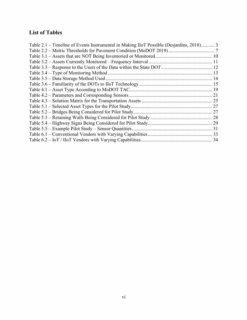
List of Tables Table 2.1 – Timeline of Events Instrumental in Making IIoT Possible (Desjardins, 2018) ........... 3 Table 2.2 – Metric Thresholds for Pavement Condition (MoDOT 2019) ...................................... 7 Table 3.1 – Assets that are NOT Being Inventoried or Monitored ............................................... 10 Table 3.2 – Assets Currently Monitored – Frequency Interval .................................................... 11 Table 3.3 – Response to the Users of the Data within the State DOT .......................................... 12 Table 3.4 – Type of Monitoring Method ...................................................................................... 13 Table 3.5 – Data Storage Method Used ........................................................................................ 14 Table 3.6 – Familiarity of the DOTs to IIoT Technology ............................................................ 15 Table 4.1 – Asset Type According to MoDOT TAC .................................................................... 19 Table 4.2 – Parameters and Corresponding Sensors ..................................................................... 21 Table 4.3 – Solution Matrix for the Transportation Assets .......................................................... 25 Table 5.1 – Selected Asset Types for the Pilot Study ................................................................... 27 Table 5.2 – Bridges Being Considered for Pilot Study ................................................................. 27 Table 5.3 – Retaining Walls Being Considered for Pilot Study ................................................... 28 Table 5.4 – Highway Signs Being Considered for Pilot Study..................................................... 29 Table 5.5 – Example Pilot Study – Sensor Quantities .................................................................. 31 Table 6.1 – Conventional Vendors with Varying Capabilities ..................................................... 33 Table 6.2 – IoT / IIoT Vendors with Varying Capabilities ........................................................... 34

vii
List of Figures Figure 2.1 – The Growth of Population vs. Connected Devices (Evans, 2011) ............................. 4 Figure 2.2 – Projected Growth of IoT Market Size and Segments ................................................. 4 Figure 3.1 – MoDOT Response to the 2020 US DOT Survey ..................................................... 17 Figure 4.1 – LTE Applications by Category ................................................................................. 22 Figure 4.2 – An IoT Gateway and Edge Computing (Assured Systems, 2020) ........................... 23 Figure 5.1 – Interstate Signs Being Considered for Monitoring ................................................... 29 Figure 5.2 – Example Pilot Study Asset Distribution ................................................................... 32
viii
Executive Summary
The Internet-of-Things (IoT) is a technology that has been growing since its inception in 2009 and as wireless technology becomes more ubiquitous, so are its applications. This technology is dependent on sensors that enable things to gather information and communicate them to other devices, computers and eventually humans. The sensors can vary from simple thermocouples to more advanced electro-mechanically devices, such as accelerometers. Even though this technology started with consumer applications, it has entered many industrial applications in factories, utilities, and smart cities. Recently these applications are being referred as the Industrial Internet of Things (IIoT). The research goal of this study is to explore the current status and viability of the IIoT technology for the purpose of asset management of transportation infrastructure or the actual built infrastructure distributed along the highway system in the state of Missouri. This research project was framed by MoDOT in two phases. Phase 1 focus was on preliminary research to assess the readiness of IIoT for initial implementation on the transportation highway system (such as: bridges, pavements, retaining walls, signs, etc.). Phase 2 will implement a pilot study on a limited number of structures to physically evaluate the technology. This report is the result of Phase 1, which summarizes the findings during this period.
A survey was administered to US State Departments of Transportation (DOTs) with questions related to asset management, monitoring and the use of IIoT. The response rate for this survey was about 48%, which is typical. The survey revealed that all DOT respondents conduct inventory and monitoring of bridges and pavements, while other assets vary. It is noted that Transportation Management System (TMS) devices and components follow some level of inventory and monitoring. Bridges and pavements are monitored in a frequency interval of one to two years and other assets vary from 1 to 5 years. When it comes to the methods used to collect data, the majority of this was done manually by visual inspections, and about a third of the data is being collected in some type of electronic device (data logger, wired, or wireless). Regarding data storage, most DOTs use some type of centralized server to store this information and more than 50 percent use an online GIS system. The use of IIoT is emerging and dynamic, considering that about half of the respondents are evaluating the technology and 30% have used it to some degree, mainly on vehicles and TMS devices, not for asset management. In comparison, the Missouri DOT is very similar to the national trends, and the desire to stay ahead and consider new technologies is noted in the status of the TMS portal and this research project.
An IIoT system is made of several key components: sensors, gateways, platforms and dashboards. The sensors can be smart or closely tied to the gateways which enhance their capabilities. Additionally, gateways enable the communication to a central server or cloud storage system. Further processing takes place on the platform and dashboard that displays the raw data and results of the field measurements. Processing may also take place at the gateway or otherwise called “edge computing” so that the computational power is distributed. Some of the key technology points to address are power to the sensors and gateways, robust (toughness) field devices, communication/processing capabilities, and data security. All these aspects need to be evaluated in making the choice for an asset monitoring system using IIoT. A solution matrix is presented for a variety of assets to be considered, but only a select number of assets are recommended for a pilot study. Bridges (3), retaining walls (2), and signs (2) are recommended for implementation on a pilot study in Phase 2. A preliminary list of bridges (12) have been

ix
identified along the state highways system, some unique ones have signs of distress and other more common in relatively good conditions. Three retaining walls and two signs have been identified within the St. Louis metro area and likely only two will be used for each type of asset. For the assets being considered, it is estimated for only the instrumentation hardware will cost about $100,000. However, the scope and selection of assets for Phase 2 is still to be finalized with MoDOT.
The civil infrastructure instrumentation and the IIoT telecommunications industries have been working towards the objective of providing continuous monitoring, and their applications are converging and overlapping as they respond to the needs of customers. An example of the products and services offered by each type of vendor is included in the Appendix B. The fact is that sensors will become more wireless, smart, and connected over time. The installation of such an IIoT system is new for the application of asset management and the Missouri DOT is at the forefront in the adoption of this technology. It is the opinion of the research team that this technology is mature enough to implement in a pilot study for the highway system.

1
1. Introduction The Internet-of-Things (IoT) is based on a new generation wireless communication technology that allows devices connected to objects or elements to communicate with computers and humans via the Internet. IoT, however, is not just about being connected, it is about combining the data from the devices with automated systems for the purpose of analyzing results and taking action. This new communication technology enables devices to communicate the data in a timely fashion without having to physically access the location of interest, but rather collecting data remotely. This technology has been embraced by others in the transportation industry for mobility purposes to enhance the roadway experience. Network carriers are on the verge of implementing the 5G technology that will allow much faster and wider bandwidth data communication of many transportation related devices (automated and connected vehicles, cameras, roadway sensors), making it more important to establish these IoT technologies in place on the most critical infrastructure. Roadway structures in service and under construction can be monitored remotely at a desired time interval and the data can be visualized and analyzed for decision making via an online dashboard. The technology is available to start evaluating viable applications in the fields of construction and engineering to monitor the condition of select infrastructure assets. This type of application would fall within the Industrial IoT (IIoT), since it is away from the consumer and its utility is at a large scale. The Missouri DOT has been proactive in the installation of transportation management systems that use roadway sensors for the traffic flow and this project would position MoDOT to embrace the IIoT technology for improved maintenance, performance and asset management.
This research project was framed in two phases. Phase 1 focused on preliminary research to assess the readiness of IIoT for initial implementation on the transportation highway system, built infrastructure (that is bridges, embankments, pavements, walls, signs, etc.). Immediately following is Phase 2 that will implement a pilot study on a small number of structures. This report is the result of Phase 1, which summarizes the findings during a period of 8 months of work.
1.1. Project Aim (Goals) The overall goal of this research project is to explore the current status and viability of the IIoT technology for the purpose of asset management of transportation infrastructure. Transportation infrastructure is defined herein as the actual built infrastructure distributed along the highway system in the state of Missouri.
1.2. Research Objectives Phase 1 of this project consisted mainly of literature review, communication with sectors in other areas of engineering technology, and vendors of IoT products. More specifically, this phase focused on the following research objectives:
• Identify assets that would most benefit from instrumentation and monitoring
• Evaluate available IIoT sensors and monitoring devices, communications networks, service application software/platforms for project purpose
• Evaluate the viability and value of current technology in monitoring MoDOT assets
2
1.1. Scope of Work - Phase 1 The scope of work for Phase 1 of this project was organized into 4 tasks, as outlined below:
Task 1 – Project Management: Coordination of the research activities were conducted by Dr. R. Luna and the administration of the project by JC Murray. Several meetings with MoDOT, vendors and AECOM expertise were conducted, and results summarized in this report. Task 2 - List and Define MoDOT Assets Suitable for IIoT Monitoring: A list of MoDOT assets (structure types) was provided by the MoDOT TAC to be considered for IIoT instrumentation and asset management. The original list was the most inclusive of all possible assets using a wide net of application. A final list of the specific assets and/or locations will be agreed on for future installation in Phase 2. Task 3 – Research and Literature Review: A literature review of market-ready IIoT sensors and monitoring devices, communications networks, service application software/platforms, and other relevant elements necessary for successful monitoring of assets will be conducted. Remote monitoring, robust survivability, long-term interoperability, and standardization of the technology will drive the search for optimal sensor systems. A list of sensors, networks, and platform operations systems will be presented with a particular correlation to the particular asset types to be monitored. The literature review also includes previous projects related to DOT remote asset monitoring, and any using IIoT, if any. Task 4 – Project Reporting and Summary: Preparation of this final report and a project summary that features the feasibility of monitoring specific assets using IIoT and the methods for a Phase 2 implementation.

3
2. Background
2.1. Historical Origins of IoT and IIoT In the early days of the Internet’s birth (1990s), the sense of a fully interconnected world seemed a far-fetched futuristic dream. But then it started happening, from PC to mainframe, then from PC to PC and “surfing the web” by many. As devices became portable and wireless (laptops, tablets and smartphones) the interconnected communication exploded, and the demand for bandwidth increased. The interconnected wireless networks, such as cellular (3G, 4G, LTE, and 5G) and Wi-Fi have been keeping with the demand of data transfer between devices. In our homes, cities and infrastructure, we want all of our things connected to all of our things. This historical evolution started since computers were able to communicate, summarized in the following Table 2.1
Table 2.1 -Timeline of Events Instrumental in Making IIoT Possible (Desjardins, 2018)
1968 Dick Morley’s group invent the programmable logic controller (PLC)
1983 Ethernet is standardized
1989 Tim Berners-Lee creates Hypertext Transfer Protocol (HTTP) – world wide web
1992 TCP/IP allows PLCs to have connectivity
1999 Internet of Things is coined by Kevin Ashton
2002 Amazon Web Services launches, and cloud computing starts to take hold
2006 OPC Unified Architecture (UA) enables secure communications between devices, data sources, and applications.
2006 Devices start getting smaller, and batteries and solar energy are becoming powerful and more economical.
2010 Sensors drop in price, enabling them to be put into pretty much everything
2016 IIoT vision emerges, involving data scientists, AR/VR, and security.
However, according to Cisco in 2011, the IoT was “born” between 2008 and 2009, which is the point when more things or objects were connected to the internet than there were people, see Figure 2.1 below:

4
Figure 2.1– The Growth of Population vs. Connected Devices (Evans, 2011)
The typical example of the IoT consumer application is what we are starting to see in our home refrigerators, notifying your car via phone that you are low on milk and routing your navigation system to take you to a store with your favorite brand of milk in stock. In the workplace, examples include inventory-tracking systems and the information stream of the supply-chain system. In industries like manufacturing, IIoT sensors in equipment, production lines, or pipelines can provide information for predictive maintenance and other essential operations. According to the Fortune Business Insights (2019), the global IoT market was valued at US$ 190.0 Billion in 2018, and it is anticipated to reach US$ 1,103 Billion by 2026 at a compound annual growth rate (CAGR) of 24.7% during the forecast period (2019 -2026). A different projection by GrowthEnabler Analysis shows a higher growth projection, as seen in Figure 2.2. The IoT market share will be dominated by three sub-sectors; Smart Cities (26%), Industrial IoT (24%) and Connected Health (20%). Followed by Smart Homes (14%), Connected Cars (7%), Smart Utilities (4%) and Wearables (3%). (GrowthEnabler, 2017)
Figure 2.2 – Projected Growth of IoT Market Size and Segments
2.2. Industrial Applications

5
A recent article of the Congressional Research Service published on June 4, 2019 defines the Internet of Things (IoT) as “…a system of interrelated devices that are connected to a network and/or each other, exchanging data without necessarily requiring human-to-machine interaction”. Essentially, it is a collection of electronic devices that can share information among each other. This is a pretty generic definition, since this technology is being applied in several sectors of the economy. The term “smart” is typically applied to this technology when the devices have sensors and processors that can analyze data and share it. Other IoT categories in different fields of application can be classified under slightly different terminology, such as: Industrial Internet of Things (IIoT), Internet of Medical Things (IoMT), Smart Cities, and Smart Homes. (Park, 2019)
IIoT have seen their initial application in the manufacturing industry, which was a natural extension of the more commercial IoT application of consumer products. In a production or factory-controlled environment the networked machines can communicate and share information with the goal of improving efficiency, productivity, and performance. This could be extended to civil infrastructure, such as a transportation system. A sector that is also related to transportation is “Smart Cities”, where systems in utilities, transportation, and infrastructure are grouped under this category. Some of the transportation applications are already in use in transportation management systems (TMS), such as interaction with vehicles in Columbus, Ohio (Park, 2019). MoDOT requested federal funds in FY2017 for the “I-70 Smart Corridor” initiative, which included IoT technologies, but the award was not made to the department. Other examples are: in San Diego, CA for street lights (Plautz 2018) and in Las Vegas Bleu Tech Park (Helms 2020).
The combination of all this data analyzed and distributed within the highway system could result in very useful information when evaluated over time. The paradigm shift enabled by the IIoT is that the traditional measurements (displacement, strain/load, pressure, tilt, etc.) made with conventional sensors, can be accomplished in an automated platform that collects and combines the data to analyze and evaluate system performance. The health of the system could be assessed by monitoring the different types of assets of the interconnected physical system, such as, bridges, culverts, earth embankments and slopes, tunnels, retaining walls, etc. The evaluation part of the analyzed data would require identifying the critical thresholds, whether they are preventative or restorative in nature, and will aid in creating more effective maintenance and increase safety.
The systematic analysis and evaluation of data from IIoT sensors could also be automated by the development of algorithms and models. Some researchers have proposed data mining algorithms, such as AdaBoost classifier, similar to those in healthcare systems. An AdaBoost classifier is an iterative algorithm method that combines multiple “weak learners” into a weighted sum that represents a boosted classifier. The process is based on four general steps: (1) Pre-processing, (2) anomaly detection, (3) clustering, and (4) AdaBooster classification (Nithya, et al., 2017). These are the initial steps for the use of artificial intelligence on large amounts of data derived from a distributed array of sensors.
2.3. How it Works: Definitions and Nomenclature
The concept of IIoT is intriguing and like any other engineered system it has some key components; here is how it works. First, we have sensors and devices that have the ability to collect, store, transmit and receive data. Some call these “smart sensors”, with ability to store,

6
transmit/receive data and do some basic processing. Second, there is connectivity, which is achieved over the Internet and local wired and wireless networks. The sensors and devices will communicate with applications and services running in the Cloud (public or private network). Data processing is the next step after data is collected, which in most cases can amount to large volumes of data, depending on the level of data sampling. Often with IIoT, it is the data processing that provides real value, since it can be vital, real-time insights into operations and maintenance. If the processing takes place close to the asset or away from the computer, it is referred as “edge computing”. Once data is processed, Artificial Intelligence (AI) and Machine Learning (ML) bring along sophisticated algorithms that applied in real-time can make sense of the incoming data. Eventually, IIoT will likely help in making important decisions on the operations and asset management. The final component is security, which has become a prerequisite for IoT. The explosion of IoT-enabled devices has increased the “attack surface” available to hackers, making cybersecurity mission critical for most enterprises.
2.4. Remote Health Monitoring Remote monitoring of assets is intended for the normal operation and performance of active assets. Some assets may be past their design life, plain old, or more modern, so the asset age will also affect the need for health monitoring. Therefore, these sensors are intended to be attached and in contact with the remote object to measure the desired response. One of the great advantages of IIoT is the interconnectivity and interoperability of the sensors. Since the IIoT has enhanced and continuous communication with edge computing, gateways, and servers; all data can be collected remotely, and the rate of data collection can be modified based on the desired outcomes. The data trends can be plotted and evaluated to assess if a physical site visit by experienced personnel or an engineer is needed for a more comprehensive evaluation. However, the intent is to minimize the amount of physical site visits. This means that if one is relying on the sensors their continued operation and reliability needs to be guaranteed.
It is important to mention that there are other technologies that could be used for remote monitoring, such as “remote sensing”. Remote sensing are techniques that are not in contact with the object being monitored, hence the use of the word remote. Typically these sensors capture a signature that travels through the air and senses the condition of the object. Some examples are: LiDAR, Multispectral Satellite, Time Domain Reflectometry (TDR), or Ground-based Interferometric Radar. These techniques have been used for monitoring, but typically are not dedicated or are slaved to work on one object; they scan the ground surface at select time intervals. These remote sensing technologies were not part of the scope of work in this study.
2.5. Asset Management Asset management in State DOTs and at the federal level has been a topic of much synergy in the past 20 years. Every State DOT is required to have an Asset Management Plan.
The Moving Ahead for Progress in the 21st Century (MAP-21) established asset management principles into law (FHWA, 2012). This 2012 legislation establishes a performance-based highway program with the goal of improving how transportation funds are allocated. In addition, MAP-21 requires each state DOT to develop a risk-based Transportation Asset Management Plan (TAMP). As defined by the Federal Highway Administration, a Transportation Asset Management Plan (TAMP) is a “strategic and systematic process of operating, maintaining and improving physical assets, with a focus on engineering and economic analysis based upon

7
quality information, to identify a structured sequence of maintenance, preservation, repair, rehabilitation and replacement actions that will achieve and sustain a desired state of good repair over the lifecycle of the assets at minimum practicable cost.”
MoDOT started the development of an asset management plan in 2005 and the latest plan was published last year (MoDOT 2019). The plan focuses on the primary National Highway System (NHS) components: roadway pavement, bridges/culverts, signals & lighting, interchanges, and right-of-way. However, at this time a limited inventory of critical assets has been identified for roadway pavement and bridges. This is part of the ongoing effort to develop an inventory of assets, as shown in the TMS website (http://modatazone.modot.org).
The measures and models used to develop the asset management plan are based on annual and bi-annual inspections and the resulting rating for the pavement or bridge condition. The pavements use the Automatic Road Analyzer (ARAN) vehicle to measure the International Roughness Index (IRI) value. If the IRI is less than 100 for interstates and other major routes, then the roadway pavement is generally considered in a good condition. Since 2017 additional ratings and associated thresholds have been developed, which include: Percent Serviceability Rating (PSR), rutting, cracking, and faulting. Below in Table 2.2 is a summary of this rating criteria. According to the MoDOT TAMP 78% of the interstate routes are in “Good” condition and for the non-interstate routes that percentage reduces to 65%.
Table 2.2 – Metric Thresholds for Pavement Condition (MoDOT 2019)
The bridge inventory and TMS is based primarily on field inspections from the Bridge Management System (BMS). MoDOT collects and maintains this inventory and condition information on National Bridge Inventory (NBI) structures since 1971. MoDOT uses the TMS to manage bridge data including inventory and inspection information. The vast majority of bridges in Missouri are inspected by MoDOT personnel with a small number inspected by consultants or by the local bridge owner. Most bridges are inspected on a two-year cycle. MoDOT has worked with FHWA to develop criteria for inspecting some lower risk structures on a four-year cycle. This is a tool available to District Bridge Engineers to help reduce the bridge inspection workload. A condition rating is assigned for the bridge’s deck, superstructure and substructure, see Table 2.3. The lowest rating of the three components is considered the bridge rating. Most of the highway bridges in Missouri are considered in “Good” condition (57.3%), however the remaining are in fair to poor condition. This indicates that the management of this type of asset is essential for the continued service and a considerable amount of the bridges may need special attention.

8
Table 2.3 – Ratings for NBIS Bridge Condition (MoDOT 2019)
NBIS Rating Thresholds for Bridge
Condition
Number of NHS Bridges / Material
Type Percent
Square Foot of Bridge Deck on NHS
9 Good Concrete: 1,255
Steel: 832 57.3% 19,794,713 8 7 6 Fair Concrete: 958
Steel: 449 38.6% 31,260,298 5 4
Poor
Concrete: 63 Steel: 86 4.1% 3,971,898 3
2 0 0
0 1 0 0 0 0 0
Total 3,643 100%
Rating scale: 9 Excellent; 8 Very Good; 7 Good; 6 Satisfactory; 5 Fair; 3 or 4 Poor; < 2 Closed
Considering the great efforts of MoDOT to develop and implement the TAMP, any future consideration of IIoT technology on transportation assets should serve the same objectives of the TAMP. Therefore, the key performance indicators (KPI) have to be developed in parallel and vetted by MoDOT. These KPIs shall then be used to support the inspections and models currently used. Once IIoT technology is proven to be reliable for remote operation in harsh and normal environments, the duplication of sensor installation at other infrastructure assets can be implemented. That is, the installation of sensors in multiple assets can be integrated to eventually manage these assets based on their performance. The adequate thresholds of performance need to be established to result in actions taken by the department.

9
3. Other State DOT Practice Other State DOTs have the same federal mandate to develop a TAMP by routine inspection of bridges, pavements and other critical assets according to the MAP-21. Under the same legislation and guidelines every State has its own plan with different metrics and thresholds. It is well accepted that for the continuous and safe operation of the highways transportation system a sound asset management plan is necessary.
3.1. Monitoring and Inspections To assess the level of monitoring and inspections of transportation infrastructure assets, one should first understand the difference of these two terms within our context. Monitoring is to observe and check the progress or quality of (something) over a period of time; or to keep under systematic review. Inspection is the careful examination or scrutiny (of something). So, most of the source of data used for asset management is based on inspections, typically carried out by DOT personnel or consultants. In contrast, monitoring is typically considered a frequent or continuous observation of the asset. For example, bridges and pavements asset management is based on at most an annual frequency, probably not frequent enough to consider it monitoring. Most DOTs rely on inspections and expert opinions. In any case, data and results are aggregated by simple functions and models to develop a metric and compare to an agreed threshold that triggers actions. These actions could be for more maintenance, repair, replacement, or do nothing.
3.2. Current Status
3.2.1. TRB 2020 Experience At the recent TRB 99th annual meeting in January 2020 the topic of asset management continues to be highly discussed in multiple sessions, exhibits, committees; totaling more than 30 events and 60+ abstracts and papers. After a careful review of specific topics like IoT and IIoT, very few papers feature such technology. Only two sessions included the topic of IoT and about half a dozen abstracts and posters were presented. In the exhibit hall, only a few vendors featured wireless interconnected sensors identified as IoT enabled. Overall, the topic of IoT on transportation infrastructure asset management is just starting to surface within the transportation infrastructure industry. In contrast, the vehicle and electro-mechanical devices that fuel the electric and autonomous automobile industry is full of sensors that are using IoT technology. One of the new applications found at the TRB meeting was TotalPave, which relies on an app installed on cell phone devices that can sense the condition of pavements when driving on a regular vehicle. They can measure the pavement condition index (PCI) and the International Roughness Index (IRI) by mounting the phone on the dashboard, as opposed to ARAN vans.
3.2.2. DOT Survey Results In addition to reviewing the literature and ongoing conferences on the topic of use of IIoT for asset management, a direct survey was administered to State DOTs to gage the current status on asset management, monitoring, and use of new technologies. A one-page survey was administered to all the DOTs with membership in the American Association of State Highway and Transportation Officials (AASHTO) Research Advisory Committee (RAC) network. A

10
copy of the blank survey instrument and the raw results are included in Appendix A of this report. However, a completed example is also shown in Figure 3.1
The response rate was about 48%, which is typical of this type of research survey. Some of the responses came from a specific section of a DOT, such as ITS, which it was not originally intended. However, the data was combined in this evaluation. In summary, we can conclude that the survey was effective to gage the general knowledge and attention being paid to remote monitoring of transportation assets.
Table 3.1 summarizes the response to the questions regarding the types of assets NOT being inventoried or monitored. As expected, all states are keeping an inventory of and monitoring their bridges and pavements. Even highway signs are being inventoried nationwide, but less monitoring is taking place. In the “Other” category, it was apparent that the ITS components (devices, cameras, fiber optic, detectors, etc.) are also being considered for inventory and monitoring.
Table 3.1 – Assets that are NOT Being Inventoried or Monitored
Type of Asset Percent of State DOTs
Not Being Inventoried
Not Being Monitored
Pavements 0 0
Bridges 0 0
Signs 0 22
Traffic signals 9 13
Culverts 17 13
Retaining walls 22 17
Soil or rock slopes 26 4
Other: -- See below --
Many DOT respondents did list “Other” type of assets that they are currently being looked at, but not necessarily in a coherent database system:
• Guardrail end treatments, pavement markings • Buildings, pavement markings • Two mentions for ITS devices (cameras, vehicle detectors, toll gantries) • Fiber optic cable • Tunnels • HMT, roadway lighting • 37 additional asset types monitored
o Current active and integrated inventory consists of 737,845 (unique IDs) assets • Drainage items, guard rail • ITS components
11
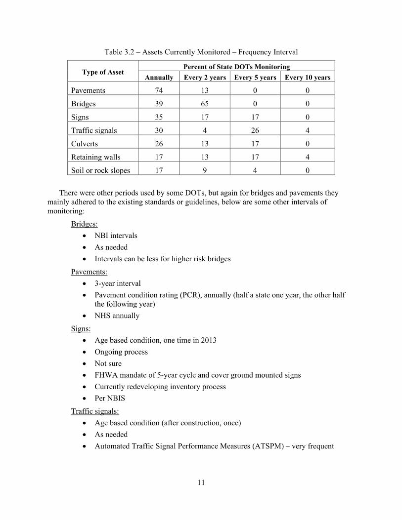
Table 3.2 – Assets Currently Monitored – Frequency Interval
Type of Asset Percent of State DOTs Monitoring
Annually Every 2 years Every 5 years Every 10 years
Pavements 74 13 0 0
Bridges 39 65 0 0
Signs 35 17 17 0
Traffic signals 30 4 26 4
Culverts 26 13 17 0
Retaining walls 17 13 17 4
Soil or rock slopes 17 9 4 0
There were other periods used by some DOTs, but again for bridges and pavements they mainly adhered to the existing standards or guidelines, below are some other intervals of monitoring:
Bridges: • NBI intervals • As needed • Intervals can be less for higher risk bridges
Pavements: • 3-year interval • Pavement condition rating (PCR), annually (half a state one year, the other half
the following year) • NHS annually
Signs: • Age based condition, one time in 2013 • Ongoing process • Not sure • FHWA mandate of 5-year cycle and cover ground mounted signs • Currently redeveloping inventory process • Per NBIS
Traffic signals: • Age based condition (after construction, once) • As needed • Automated Traffic Signal Performance Measures (ATSPM) – very frequent

12
Culverts: • Large culverts with bridge cycle, small culverts under development • Annually sample through Maintenance Rating Program (MRP) • Depends on general appraisal rating (GA); over 90,000 on record
Retaining walls: • Annually sample through Maintenance Rating Program (MRP) • Once, 2015 inspection • Updates annually • No systematic monitoring • Every 5th year
Soil and rock slopes: • At problem locations, custom system, continuous monitoring • Select slopes periodically • Annually sample through Maintenance Rating Program (MRP) • Once, 2019 slope study • As needed, based on activity and risk • Depending on severity and risk • Monitor high risk slopes
Once the type of inventory and the level of monitoring was determined within the DOT, the following question was: Who uses the data collected from the inventory and monitoring? The responses are summarized in Table 3.3.
Table 3.3 – Response to the Users of the Data within the State DOT
State User of the Inventory and Monitoring Data
Colorado
Asset managers assigned to each class of asset. Colorado DOT widely available data through Online Transportation Information System (OTIS). This also feeds to centralized GIS ESRI driven platforms that can also be accessed by anyone in the organization
Connecticut Asset specific groups Delaware No response
Florida Maintenance, Pavement Design, State Materials Office, District Production, Planning, Traffic Operations
Idaho District Planners/Engineers Illinois Program development Kentucky Maintenance, Planning, Leadership, Budgets Massachusetts No response Michigan Planning, Design, Bridge Bureau, Maintenance, Consultants Minnesota AMPO, Maintenance, Planning

13
New Mexico Pavement Bureau, Bridge Bureau, Project development, Planning North Dakota Throughout the department, but primarily by Engineering Divisions Ohio Organizational access, public, FWHA, local public agencies, etc. Pennsylvania Asset management, Maintenance, Planning, Design South Dakota Operations, Planning, and Engineering Tennessee Maintenance Division, Structures Division Utah Lots of internal uses by nearly every organization, public facing as well Vermont Asset Management, Performance Section, Maintenance Bureau/Districts Virginia Load rating engineers and … Wyoming Materials, Bridge, Traffic
Most State DOTs are conducting a monitoring activity at different frequencies, however the
methods used differ. One common denominator was that DOTs mainly use a manual method to collect the data or interest. To a lesser degree, about one-third uses some type of datalogger with a wired or wireless network. Two DOTs or the equivalent of nine (9) percent of the responders actually acknowledge the use some type of IIoT device to collect the data. Table 3.4 summarizes the methods used for monitoring by percentage.
Table 3.4 – Type of Monitoring Method
Method Used Percent of State DOTs
Manual (needs access to site) 96
Datalogger 35
Wired network 30
Wireless network 30
IIoT device 9
Other method 39
The following remarks are a summary of the methods used other than the ones listed as a choice:
• Fugro is contracted by CDOT to collect pavement condition on state highways. They have been recently extended to include video analytics that also collect other roadway and roadside assets on a yearly basis. Most recently, they have started to use a defects protocol, that Fugro then uses on their yearly data collection runs that identify if defects in the asset exist. Fugro uses their own data collection devices, equipment, and fleet vehicles using this equipment.
• Pavement is monitored by rut, crack and ride van
• Pavement is monitored by IRI, rut, crack, and ride van
• Vehicles with sensors

14
• Agile Assets TAMS software
• ESRI Collector infrastructure (on-prem) using data plans and GPS hand-held units
• Automated Pavement Condition Assessment (ARAN)
• Pavements by laser and HD photography
• Bridges, culverts, walls, slopes manually. Signals are fiber. signs, pavement marking are by Lidar, pavement is driven (manual)
• ARAN van for pavement
Once the data is collected, the data must be stored for current and future use. The data needs to be combined, co-located with the asset and eventually analyzed to take some action. The fourth question asked in the survey was: Where is the monitoring data stored? Table 3.5 summarizes the response to a multiple-choice question. Most DOTs used some type of centralized server to store this information and more than 50 percent use an Online GIS system.
Table 3.5 – Data Storage Method Used
Method Used Percent of State DOTs
Individual files/computers 30
Central server 83
Online or in the Cloud 61
GIS online system 65
Regarding data management and analyses of the data collected, the use on a dashboard or online platform was asked (Question 5). That is, the ability to readily manipulate and query the database for the purpose of decision making and to take action. The response to this question yielded a 70% positive response.
Finally, a specific and direct question regarding the State DOTs experience with IIoT, resulted in the following response summarized in Table 3.6

15
Table 3.6 –Familiarity of the DOTs to IIoT Technology
Familiarity to IIoT Technology Percent of State DOTs
Unfamiliar with this technology 22
We have heard of and may consider using technology 22
Currently evaluating this technology 48
We have used this technology 30 Note: Some State DOTs responded twice in evaluating and using the technology.
Of interest in this set of responses, there appears to be an interest in the uptake of IIoT technology, since about 48% of the DOTs are currently evaluating the use of IIoT and 30% are already using the technology. Examples of the ongoing projects that are considering the use of these technologies, resulted in the following:
• Delaware: AI-ITMS (https://deldot.gov/Programs/itms/index.shtml?dc=projects) • Florida: Testing connected automated use, adaptive signal control technology • Illinois: Devices installed at a test site for lighting • Michigan: Connected vehicle-based technology and applications • Ohio: Drive Ohio program added fiber optic, smart devices, vehicle sensors, etc. to allow
organizations to test autonomous and connected vehicle technologies in multiple corridors throughout the state
• Utah: Looking at auto devices • Vermont: Engaged in a research project with the University of Vermont to evaluate the
feasibility of RFID technology for traffic sign and other asset monitoring • Virginia: A feasibility (research) project is underway to develop a wireless strain gauge
for a pavement section in Blacksburg, Virginia • Wyoming: Connected vehicles included with sensors such as speed or signals
Based on the responses, the majority of applications being considered are related to traffic management system (TMS) and vehicle tracking. On the other hand, the State DOTs that are currently using IIoT technology for asset management, the following list includes some examples:
• 8,000 devices and 1,600 miles of fiber connecting devices • Using mobile IoT approach as described above for both asset inventory and asset
condition on a yearly basis. In addition, the ITS/Traffic Operations division have 8,000 devices and 1,600 miles of fiber connecting our devices
• Isolated, site specific sensor applications in the past • Toll pricing algorithms-based congestion for managed lanes • US-2 Cut River Bridge Pilot Deployment, Pilot CV Pavement Condition data collection • Developing an enterprise streaming platform (ESP) to capture, analyze, and distribute
real-time data

16
• Connected vehicle (DSRC), ATSPM on signal system, blue tooth, radar, other passive data collection for traffic operations.
3.2.3. Comparison to MoDOT The Missouri DOT, as the initiator of the survey, is being included in this report as an individual respondent. However, it was included in the previous section as one of the states that responded to the survey. MoDOT responded similar to the other states, which was expected as they all are required to follow transportation asset management plans. The use of technology to monitor the performance or health of the assets is not significant, most of this is done by manual inspections. However, data storage in the TMS inventory as an online GIS database is relatively superior. It appears that there are many ways to store the data and not all necessarily being recorded in the central database or inventory. Figure 3.1 shows the survey response from Missouri, which was actually completed as a team effort by the TAC for this research project.
One of the important considerations when reviewing the responses to this survey, is that the respondents came from different divisions at the DOTs. For example, when the respondent belonged to the TMS or ITMS division, they would be more familiar with sensors, RFID and the tracking of assets using technology. This contrasted with respondents belonging to other divisions within the DOT that were more in the structural maintenance or asset management side of the organization.

17
Figure 3.1 – MoDOT Response to the 2020 US DOT Survey

18
4. Components of an IIoT System for Asset Monitoring In order to fully evaluate the use of an IIoT system for asset monitoring, the research team proposes to conduct a pilot study for a select number of assets. This will require the design of a system with a limited scope. This section of the report will present a high level design of such a system, since the actual design needs to be structure specific and interconnected to establish the condition of the assets based on the data collected. A formal process to identify the data requirements and the key performance indicators, and thresholds will be conducted during the formal design of such a system. For the purpose of Phase 1, only the components, architecture, and data flow processes will be described.
4.1. Infrastructure to Monitor
4.1.1. Types of Assets One of the first tasks in this Phase 1 was to meet with MoDOT and discuss the scope and intent of the project and identify the types of assets that would be desirable to monitor. After the kickoff meeting with the MoDOT TAC, the research team received a classification of the assets to be considered for this project. They were categorized in two groups (A & B), which splits them in the order of priority. Table 4.1 is the table that was presented by the Technical Advisory Committee (TAC) on November 26, 2019.
The last column includes the initial parameters to consider for monitoring by the proposed system. This list is quite complete, and it includes a diverse type of assets, but is not considered exhaustive. Additionally, the importance of the asset for the continuity of service was considered for the type of assets presented in Table 4.1, and that list can be considered ranked by importance.
There could be more assets that could be monitored. For the purpose of the pilot study an even shorter list will be more feasible. Other types of assets that could be considered and may need to be prioritized are:
• Dynamic traffic signals
• Toll or scales installations
• TMS monitoring devices
• Electric car charging stations
• Light towers or pole installations
• Other

19
Table 4.1 – Asset Type According to MoDOT TAC
Priority / Category Asset Type What MoDOT would like to monitor
(at a minimum)
A
Road surface (pavements) Moisture content, deflection, cracking
Bridges and culverts ≥ 20 ft + tunnels
Cracking, corrosion, delamination, substructure alignment/settling, scour
Retaining walls Alignment, moisture/pressure, cracks
Bridges and culverts < 20 ft Scour/undermining, settlement, alignment
Signs and supports Structural integrity, cracks, height of mast arm, alignment, corrosion, retro-reflectivity
Traffic signals - see Signs Structural integrity, cracks, height of mast arm, alignment, corrosion
Slope failures/slides (both active and post-repair)
Movement, moisture, pore pressures, seismic
Rock falls Movement, seismic
B
Roadway barrier (includes concrete barrier, curb, guard rail, guard cable, with delineators and glare shields)
Tension, alignment, collision notification, height (maybe not continuous, probably with ARAN)
Impact attenuators - include with Roadway barrier Collision notification
Lighting (includes high mast and roadway lighting) - see Signs
Bulb status, illumination levels, corrosion (lowering device and baseplate)
Storm sewer (drop inlets, MS4) Clear pathway/backups, alignment, hydraulic flow, corrosion
Environmental Water quality (conductivity, pH, chlorides, turbidity, etc.)
4.1.2. Design Life and Age of Assets It is well known that most civil infrastructure is designed to provide a good level of service throughout its design life. However, many of these structures have already exceeded their design life, that is, their age is greater than their original design life. At times these structures have been modified, rehabilitated, or retrofitted to improve their level of service. When this happens, it is more difficult to define the design life. For new infrastructure, there is a trend to use materials and methods that will allow for a longer design life (100+ years).
20
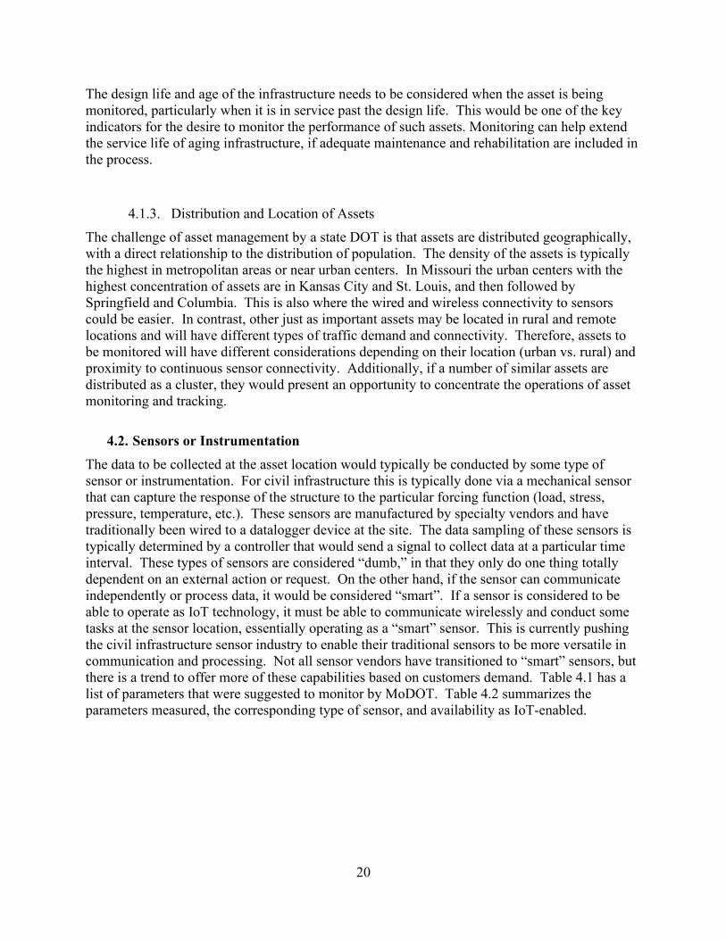
The design life and age of the infrastructure needs to be considered when the asset is being monitored, particularly when it is in service past the design life. This would be one of the key indicators for the desire to monitor the performance of such assets. Monitoring can help extend the service life of aging infrastructure, if adequate maintenance and rehabilitation are included in the process.
4.1.3. Distribution and Location of Assets The challenge of asset management by a state DOT is that assets are distributed geographically, with a direct relationship to the distribution of population. The density of the assets is typically the highest in metropolitan areas or near urban centers. In Missouri the urban centers with the highest concentration of assets are in Kansas City and St. Louis, and then followed by Springfield and Columbia. This is also where the wired and wireless connectivity to sensors could be easier. In contrast, other just as important assets may be located in rural and remote locations and will have different types of traffic demand and connectivity. Therefore, assets to be monitored will have different considerations depending on their location (urban vs. rural) and proximity to continuous sensor connectivity. Additionally, if a number of similar assets are distributed as a cluster, they would present an opportunity to concentrate the operations of asset monitoring and tracking.
4.2. Sensors or Instrumentation The data to be collected at the asset location would typically be conducted by some type of sensor or instrumentation. For civil infrastructure this is typically done via a mechanical sensor that can capture the response of the structure to the particular forcing function (load, stress, pressure, temperature, etc.). These sensors are manufactured by specialty vendors and have traditionally been wired to a datalogger device at the site. The data sampling of these sensors is typically determined by a controller that would send a signal to collect data at a particular time interval. These types of sensors are considered “dumb,” in that they only do one thing totally dependent on an external action or request. On the other hand, if the sensor can communicate independently or process data, it would be considered “smart”. If a sensor is considered to be able to operate as IoT technology, it must be able to communicate wirelessly and conduct some tasks at the sensor location, essentially operating as a “smart” sensor. This is currently pushing the civil infrastructure sensor industry to enable their traditional sensors to be more versatile in communication and processing. Not all sensor vendors have transitioned to “smart” sensors, but there is a trend to offer more of these capabilities based on customers demand. Table 4.1 has a list of parameters that were suggested to monitor by MoDOT. Table 4.2 summarizes the parameters measured, the corresponding type of sensor, and availability as IoT-enabled.

21
Table 4.2 – Parameters and Corresponding Sensors
Parameter Types of sensors Available
“Smart” or IoT-enabled
Strain Strain gauge – electrical resistivity Strain gauge – vibrating wire Yes
Load Load cell – electrical resistivity Load cell – vibrating wire No
Displacement
Crack meters (vw and RDT) Strand meters (vw) Cable potentiometer (cpot) Linear variable displacement transducer (LVDT)
Yes
Inclination On-structure: Tiltmeter (vw, MEMS, electrolytic) In-ground: Inclinometer, embedded, MEMS),
Yes
Vibration/ acceleration
Accelerometer (MEMs) Accelerometer Yes
Temperature (ambient)
Thermistor Thermocouple (may be included in sensors) Yes
Humidity Resistive humidity sensor (often includes temp) Yes
Video CCTV camera Miniature HD camera Maybe
Pore water pressure Piezometers (vw) Piezometers (semiconductor or resistive) Maybe
Water level (depth) Level meter (ultrasonic distance meter) Piezometer (submerged pressure gauge) Yes
Internal temperature Maturity meter (internal temperature/humidity) Yes Water quality (PH, conductivity, turbidity)
IoT water sensors (tbd) Maybe
Note: Section 6 and Appendix B contains information of select vendors for specific sensors and instrumentation.

22
4.3. Device Communication One of the advantages of IIoT technology is the inherent communication of the sensor technology. In the civil infrastructure monitoring industry there has not been a total switch to the “smart” sensors and the communication has been enhanced by connecting a series of “dumb” sensors to a communication box that would process and send the information, often this is still done wired to the sensor and wireless to a thread or gateway. More and more the sensors are being combined to directly communicate to the wireless gateway. It was found that very few sensors can actually communicate among each other, they often rely on a communication box (IoT gateway) to route the data flow.
The Long Term Evolution (LTE) technology is a standard for wireless broadband communication for mobile devices, sometimes referred as 4G LTE. IoT-enabled sensors and devices use the available cellular wireless network consisting of LTE technologies: Cat-1, Cat-4, Cat-M1, and Cat NB1. The primary differences between these technologies are bandwidth, power, and cost. Cat-4 is most often used for higher-bandwidth applications, while CAT-NB1 is more practical for lower bandwidth applications (like devices that just need to send simple binary messages). Cat-M1 and CAT-NB1 are best designed for applications that are related to IoT because they use lower bandwidth and use less power. The expectation of the 5G cellular technology will mainly affect devices connecting with higher bandwidths and longer duration but will not affect the use of most IoT devices. Figure 4.2 shows a comparison of these cellular technologies and their LTE application by category.
Source: Particle (2020)
Figure 4.1 – LTE Applications by Category
4.4. Gateways and Edge Computing An IoT gateway is a hardware solution to enable IoT communication, usually device-to-device or device-to-cloud. The gateway typically houses application software that performs essential tasks, including edge computation. Edge computing brings these capabilities closer to the point where data is generated, rather than on a centralized server of the cloud. The devices can be enabled to take actions, aggregate and filter data locally. Once the required edge computations

23
have taken place, the desired information is communicated to the cloud or a server to enable anyone to use the information at a desktop or tablet to make decisions. Figure 4.3 shows a diagram of the relative function of an IoT gateway.
Figure 4.2 – An IoT Gateway and Edge Computing (Assured Systems, 2020)
Some key technology challenges for the future success of the IoT ecosystem are as follow:
• A large deployment of IoT devices will need more data collection/processing demands and intelligent analytic requirements
• The built-in computing power, storage capability and intelligence of algorithms • The effective collaboration of IoT gateways along with backend/cloud systems • The effect of this new technology on the DOT’s IT infrastructure and networking • The impact device interoperability standards or lack thereof
4.5. Dashboards and Platforms
Once data and information from the gateway is delivered to the cloud, it is accessible for use in a display dashboard. Such dashboards are customizable to display data in textual or graphic form. Data can be averaged, filtered, and analyzed in real-time to plot the desired output and evaluate trends or examine threshold criteria. It is at this level that the big data tools, such as algorithms for artificial intelligence (AI) and machine learning (ML) would be executed to aid in the interpretation of the asset performance. The platform for an IoT system is a kind of operating system (software) that runs the communication and connectivity of sensors through the gateway, cloud and dashboard. Some examples of these platforms are Microsoft Azure, Amazon AWS IoT Core, IoT Connect, etc. However, many vendors create their own communication protocols to interact with the sensors and report to the dashboard application.
4.6. Matrix of Solutions The above sections have outlined the components and system that would comprise an IIoT monitoring system for transportation assets. The unique innovation here is to conduct a digital

24
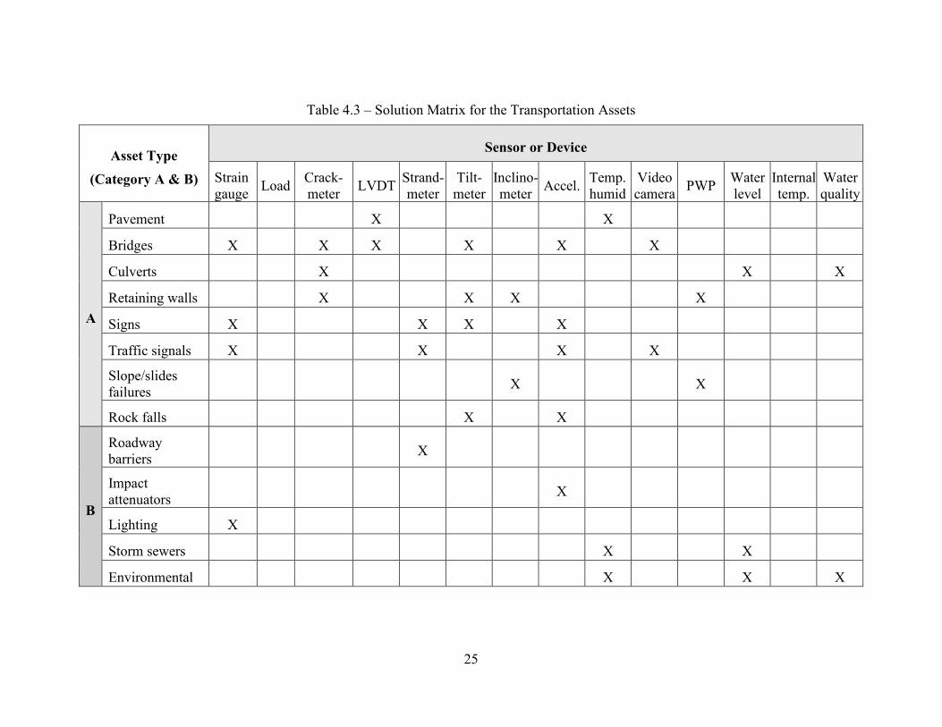
transformation of what are considered static permanent assets so they can be managed more efficiently. The intent of the level of monitoring is not to study the behavior of the existing structures, but rather have a few key performance indicators (KPI) that may provide an insight on the current condition of the asset. The matrix shown in Table 4.3 could serve to understand and decide what sensors and devices are needed for the respective assets. At this time, only the Category A assets have been considered for implementation in the pilot study.
25
Table 4.3 – Solution Matrix for the Transportation Assets
Asset Type
(Category A & B)
Sensor or Device
Strain gauge Load Crack-
meter LVDT Strand-meter
Tilt-meter
Inclino-meter Accel. Temp.
humid Video camera PWP Water
level Internal temp.
Water quality
A
Pavement X X
Bridges X X X X X X
Culverts X X X
Retaining walls X X X X
Signs X X X X
Traffic signals X X X X
Slope/slides failures X X
Rock falls X X
B
Roadway barriers X
Impact attenuators X
Lighting X
Storm sewers X X
Environmental X X X

26
5. A Pilot Study - IIoT for Transportation Infrastructure In order to thoroughly evaluate if the IIoT technology is ready and applicable to transportation infrastructure asset management, a pilot study should be undertaken. A pilot study is not a proof of concept activity, but rather a full implementation of a system at a limited scope that would be in service for a determined period of time. In order for this to be effective, the research team needs to involve the asset management team, so the implementation would result in a return on investment to MoDOT. Ultimately, the size of the pilot study would depend on the funding level. However, it is estimated that at least two bridges, two retaining walls, and two overhead signs would be included in the pilot study. There shall be an alternate for each type of asset in case of unforeseen circumstances found with one of the currently selected asset structures.
5.1. Criteria for Sites, Structural Assets The following sections will discuss the criteria used for the selection of the proposed sites that would comprise the pilot study.
5.1.1. Urban, Rural, Suburban As discussed in section 4.1.3, transportation infrastructure is distributed throughout the state and the number of the assets will vary according to the population density. For an urban and suburban setting, the St. Louis metropolitan area was selected and for the rural or remote setting, it is likely that assets along the I-44 corridor will be used.
5.1.2. Proximity and Density of Sensor Array The location of the asset relative to the location where the data will be warehoused or analyzed may be a factor on how the data communication will flow. For example, a remote asset like a bridge may need special communication infrastructure if it needs to send the data a long way. Given that the data most likely will be housed in the “cloud”, this may be less of an issue. Still factors like power to the sensors and gateways will be different depending on the remote location of the asset. The size and complexity of the structural asset will also influence the number of sensors installed. For example, a small bridge or culvert may need only a few sensors, when a major bridge may need dozens of sensors installed.
5.1.3. Scope of Implementation At this time and in collaboration with MoDOT, we have defined the limited scope of the pilot study to three (3) bridges (one alternate), two (2) retaining walls, and two (2) overhead highway signs. Table 5.1 lists the type of assets and the anticipated type of sensors/devices that will be used to monitor the performance of the asset. Pavements are currently being monitored in most States DOTs including MoDOT and have a well-established monitoring system, the ARAN van. This system collects pavement data, which is inventoried, and becomes accessible via the TMS. The ARAN system does involve a significant amount of human judgement and observation, which adds value to the pavement evaluation. Even though pavements are a top priority category, they were not chosen for this pilot study, which would appear a duplication of effort and redundant.
The age of the asset relative to their design life should also be considered. Even though this system is not designed as a surveillance system for high-risk assets, some consideration is being

27
given to the fact that these older structures would have the first priority. At least one asset should be one that is past or advanced in its design life. The more common and numerous assets shall also be monitored, regardless of their age or condition.
Table 5.1 – Selected Asset Types for the Pilot Study
Asset Type
Sensor or Device
Strain gauge
Crack-meter LVDT Strand-
meter Tilt-meter
Inclino-meter Accel. Video
camera PWP
Bridges X X X X X X
Retaining walls X X X
Signs X X X X
Other (TBD)
5.2. Specific Assets Being Considered
5.2.1. Bridges Several bridges were proposed by MoDOT during phase 1 of this project. Some bridges were located in a rural setting and others closer to the St. Louis metropolitan area. Table 5.2 summarizes the bridges that are currently being considered.
Table 5.2 – Bridges Being Considered for Pilot Study
Br. Design No.
Location County Yr. built
Length (ft)
Bridge Type
L0093 (+)
I-44 WB, mm 135 (rural) Pulaski 1954 754 STRG - steel girder over creek
A8540 (+)
St. Mary’s Rd. / I-44 (rural) Franklin 2018 212 T-BM - Overpass 1-44
A8603 (+)
Hwy E / I-44 (rural) Franklin 2018 84 T-BM - Overpass I-44
A1006 (+)
I-270 / I-44 Ramp St. Louis 1962 371 STRG
A1796 (*)
I-44 / Meramec River St. Louis 1968 1308 STRG
A3028 (+)
MO 366 / US50 St. Louis 1983 155 STRG
A4783 (+)
I-64 EB / Creve Coeur Creek
St. Louis 1988 182 T-BM

28
A4784 (+)
I-64 WB / Creve Coeur Creek
St. Louis 1988 182 T-BM
A4785 (+)
I-64 EB / Creve Coeur Creek
St. Louis 1990 180 T-BM
A1501 (*)
14th Street NB / I-64 St. Louis City
1964 7847 STRG
A2394 (-) I-44 EB / Wellington Ct. (creek)
St. Louis City
1971 598 STRG
A3162 (+)
I-44 EB / Broadway / S. 7th Street
St. Louis City
1976 3175 STRG
Notes: (*) bridge will be rehabilitated soon; (+) Easy access; (-) Ladder or bucket access
5.2.2. Retaining Walls In fact, it was an issue with a retaining wall along I-44 that sparked the initial interest for this IIoT project. Jennifer Damery (St. Louis District Geologist) from MoDOT was working with an AT&T service provider to install some instrumentation and monitor it remotely, but that has yet to take place as of the writing of this report. Retaining walls are composed of a structure, soil backfill, and sometimes anchors or reinforcement. Therefore, to evaluate the performance of these assets, more than one of these need to be monitored. Currently, we anticipate monitoring both the structure and the backfill. Table 5.3 lists the specific retaining wall assets that are being considered for the pilot study in phase 2 of this project.
Table 5.3 – Retaining Walls Being Considered for Pilot Study
Location County Yr. built
Type Remarks
I-44 WB at Macklind Ave.
St. Louis City
<1960 Concrete Wall connected to bridge is cracking.
I-270 NB Ramp to Route 180 (St. Charles Rock Rd., Bridgeton)
St. Louis ? Concrete Wall is tilting toward road.
Rte. N at Emerling Dr., (Cool Valley)
St. Louis ? Gabion and concrete
Gabion wall is bowing outward toward creek. When failing section is replaced, the new wall could also be monitored.
Other?
5.2.3. Signs The signs along the highway transportation system are many and of different types. They can be relatively large signs, such as those overhead an interstate signs supported on both sides of the road (steel column supports with a truss to span lanes); in contrast to the small single support

29
signs for highway exits or traffic safety warnings. The highway signs are identified and managed via a GIS database in the MoDOT datazone, but there are internal records that contain more detailed inspection reports. At this time, MoDOT has identified two interstate highway signs for initial consideration, identified in Table 5.4. It is understood that more signs could be made available. Figure 5.1 shows current photographs of the signs along the interstate route.
Table 5.4 – Highway Signs Being Considered for Pilot Study
Location County Type Remarks
I-44 WB, near Lindbergh exit
St. Louis Cantilever 30’ cantilever, may have power for lighting
I-270 EB, approaching I-70 exit
St. Louis Span Aluminum truss that spans over 5 lanes, has power for lighting
Other signs may be available
Figure 5.1 – Interstate Signs Being Considered for Monitoring
5.2.4. Other (ITS or TMS infrastructure) An additional type of asset to be considered are the TMS assets used for traffic and intelligent transportation system. One unique feature of these signs is that they are already connected. Since they feature a display to inform the traveling public, they do have wired data connectivity and power. This make this type of asset easier to install and monitor in the long term.
5.3. Pilot Study Plan – Limited Scope Taking in to account the criteria mentioned above, a pilot study plan has been outlined in Table 5.5 and a point of reference to estimate the number of sensors per structure. The total number of sensors may amount to 65 and at an estimated $1,000 per IIoT-enabled sensor, this would likely reach $65,000 just for sensor hardware. At this time no formal quotes have been secured from

30
vendors, since a more specific scope needs to be developed in collaboration with MoDOT once the assets have been finalized.
Additionally, at least one IIoT gateway will be needed at each structure asset location, if they are apart from each other. If the structural assets are close by, like two twin bridges or signs, they could share one gateway. Each gateway costs approximately costs $4,000, so for nine (9) assets, the total cost would be at least $36,000. A secure communication software is also a must to exchange data from the assets to the storage server and it would be an additional $4,000 including the cloud storage service. Therefore, it is estimated that the total cost for hardware for this limited scope of instrumentation would reach about $100,000, just for hardware. The installation and engineering services would be in addition to this amount.

31
Table 5.5 – Example Pilot Study – Sensor Quantities
Type of Asset Quantity and description Type of Sensors Number of
Sensors
Total Sensors
Bridges 3 total, two close to St. Louis and one remote
Strain gages (vw) 6 18
Vibration (MEMs) 3 9
Tiltmeter (MEMs) 2 6
Crack meter (displacement) 2 6
Retaining walls
2 total, one close by and one far relative to St. Louis
In-place Inclinometer (MEMs) and Tiltmeters (MEMs)
3 6
Pore pressure (vw) 2 4
Crack meter (displacement) 2 4
Interstate overhead sign
2 total, one close by and one far relative to St. Louis
Strain gages (vw) 2 4
Vibration (MEMs) 1 2
Sub-centimeter position MEMs 2 4
Total Number of Sensors 63
32
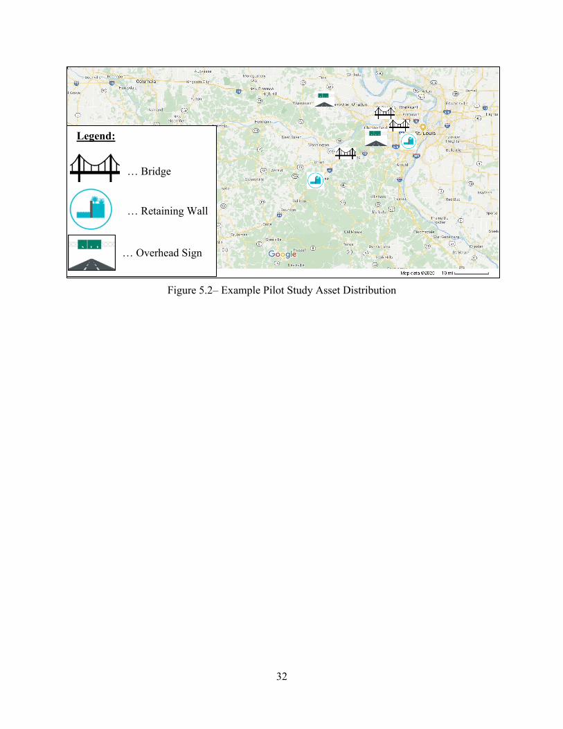
… Bridge
… Retaining Wall
… Overhead Sign
Legend:
Figure 5.2– Example Pilot Study Asset Distribution

33
6. Potential Vendors for IIoT Instrumentation During the course of this project (phase 1), a search for vendors that could install sensors and devices on the transportation assets of interest was conducted. It was found that there is not one type of vendor that provides this as a regular service. However, there was significant interest from some that mentioned this is an upcoming market, growing rapidly. Several vendors were contacted in person at conferences or remotely via telephone, web, or email. The two conference events that were attended were the TRB Annual Meeting in Washington DC (January 2020), and the IoT In Action in Chicago (February 2020). Based on this review of the available vendors, it was determined that there are two general types of vendors. On one hand, there is the (1) conventional instrumentation (sensor) vendor for monitoring of civil infrastructure, and on the other hand is the more (2) Tech IoT vendor that is more focused on the data communication and end-to-end solutions. Essentially, these two types of vendors have been converging to provide a similar service for asset monitoring and currently there is a lot of overlap.
6.1. Conventional Sensor Vendors Sensors are used for many purposes and have become very prolific in many other industries. However, in the civil infrastructure world the installation of instrumentations (sensors) is very well established. Monitoring structures has been a specialty niche using sensors of many types, but in recent times they have lagged behind compared to other industries. One of the main factors they lag behind has been regarding wireless, power management, and onboard processing. The list of vendors in Table 6.1 shows some of these companies that have been traditional companies in civil infrastructure instrumentation with different levels of progress in the IIoT market.
Table 6.1 – Conventional Vendors with Varying Capabilities
Company Claims
IIoT Remarks Year Est. Website
Campbell Scientific No
Specialty in data logger and DAQ. Use other sensors in their solutions. Applications are beyond civil.
1974 https://www.campbellsci.com/
RST Instruments No Specialty in sensors for civil,
use wireless. 1977 https://rstinstruments.com/
GEOKON No Obtains wireless capabilities via Sensemetrics integration. Dams.
1979 https://www.geokon.com
Durham Geo Slope Indicator (DGSI)
No
Wide array of sensors including inclinometers for monitoring all types of civil infrastructure.
~1958 https://durhamgeo.com/
BDI Testing No Focused on bridges, some wireless gateways. Bridges. 1989 http://www.bditest.com

34
Sensemetrics Yes
New company serving the more traditional companies, not clear if they manufacture sensors.
2014 https://sensemetrics.com/
Worldsensing Yes Specializes in the connectivity of sensors manufactured by others
2008 https://www.worldsensing.com/
Resensys Yes Wireless smart sensors manufacturer can do end-to-end solution. Bridges.
2008 https://www.resensys.com/
6.2. IIoT Vendors
The IoT vendors have been rapidly growing and are more dynamic enterprises. They initially focused in the consumer market and are moving into the industrial markets, hence IIoT. This type of vendor comes from a different engineering discipline (computer, electrical, and software), and are quite diverse across the markets they serve. Often, they sell their technology based on a well-defined return on investment, which may not be the case for a public or government institution. IIoT vendors are less familiar with the operations and requirements of a DOT and few have served this market. During the brief duration of this project none of the IIoT vendors contacted had previously monitored structures for a DOT. However, they were more familiar with traffic systems, vehicle tracking, and fleet management.
Table 6.2 – IoT / IIoT Vendors with Varying Capabilities
Company Sensors Remarks: Website
AVNET No
Engaged in several teleconferences to arrive at a pilot study solution.
https://www.avnet.com/wps/portal/us/solutions/iot/
MOXA No
Met at the IoT In-Action Conference, Chicago, IL.
https://moxa.com/en/solutions
Iconics No Referral via Microsoft IoT. https://iconics.com/Solutions/IoT
Particle No
They contacted RL directly, do not make sensors, only the connectivity.
http://www.particle.io
35
Arrow Yes
Met at the IoT In-Action Conference and Microsoft connected.
https://www.arrow.com/en/iot/iot-industrial-solutions/overview
Bright Wolf No Referral via Microsoft IoT. https://brightwolf.com/industrial-iot-solutions/
Aritron Technologies No
Met at the IoT In-Action Conference, Chicago, IL.
http://www.aritron.com
7. Conclusions and Recommendations This research project investigated the possibility for a digital transformation in asset management in the highway infrastructure system. Currently, most DOTs conduct their asset management by creating inventories and monitoring some of their assets by the use of manual visual inspections. The use of IIoT technology could reinforce the current manual inspection efforts and automate some of the monitoring and surveillance actions. The use of IIoT sensors that can communicate to a gateway and then a central location would allow for the longitudinal evaluation of the assets and take actions, such as maintenance, repair, or replacement of assets.
There is a tendency by engineers to place sensors on assets that are in a state of disrepair or their performance has been compromised. This is a bit reactive relative to the condition of the asset, but proactive in preventing a more catastrophic condition. Such actions are more of a surveillance monitoring system to prevent excessive damage or collapse. However, DOTs typically will not let structures reach this state of disrepair. On the other hand, a more general asset monitoring for all types of assets would consist of the installation of sensors throughout the highway system. This large endeavor would be an unreasonable expense and difficult to justify. A select number of assets that are more critical and reaching the end of their design life would be more viable. As the use of sensors becomes more prolific and the connectivity is more established, this initial network could grow in the future. Therefore, developing an IIoT monitoring system for DOT assets should be a balanced approach involving personnel from several members of the organization.
MoDOT provided an initial list of twelve (12) desired asset types to consider on this project, which are all reasonable and categorized in two priorities (A & B). Given the need to reduce this selection for the pilot study, it is recommended to include three types of assets in category A: bridges, retaining walls, and overhead signs. Pavements are the highest priority asset and are already being monitored using ARAN vans statewide, thus they are not recommended for the pilot study at this time. Several specific assets have been identified at this time, but as the plans and budget of the pilot study are refined the installation of the array of sensors will be determined. Some vendors have been contacted and are ready to provide formal quotations for each specific structural asset. The selection of the specific assets and vendors will be made in Phase 2.
The civil infrastructure instrumentation and the IIoT telecommunications industries have been working towards the objective of providing continuous monitoring, and their applications

36
are converging and overlapping as they respond to the needs of customers. The fact is that sensors will become more wireless, smart and connected over time. The installation of such an IIoT system is new for the asset management application and the Missouri DOT is at the forefront in the adoption of this technology. It is the opinion of the research team that this technology is mature enough to implement in a pilot study for the highway system.

37
8. Cited References
Assured Systems (2020). “IoT Gateways”, https://www.assured-systems.com/us/product-category/IoT-Gateways/ Online. (June 10, 2020).
Fortune Business Insights (2019). “Internet of Things (IoT) Market Size, Share and Industry Analysis By Platform (Device Management, Application Management, Network Management), By Software & Services (Software Solution, Services), By End-Use Industry (BFSI, Retail, Governments, Healthcare, Others) And Regional Forecast, 2019 – 2026”. Report ID: FB100307. Online (May 22, 2020).
Desjardins, J. (2018). “Timeline: The History of The Industrial Internet of Things”. Visual Capitalist, https://www.visualcapitalist.com/timeline-industrial-internet-things/ Online. (May. 20, 2020).
Evans, D. (2011). “The Internet of Things – How the Next Evolution of the Internet is Changing Everything”. White Paper, Cisco Internet Business Solutions Group (IBSG), April, 11pages.
Ezechina, M.A., Okware, K., and Ugboaja, C. (2015). “The Internet of Things (IoT): A Scalable Approach to Connecting Everything”. The International Journal of Engineering and Sciences, Vol. 4, No. 1, 9-12pp.
FHWA (2012). “Moving Ahead for Progress in the 21 Century”. Federal Highway Administration. https://www.fhwa.dot.gov/map21/ (May 29, 2020).
GrowthEnabler (2017). “Market Pulse Report, Internet of Things (IoT)”. GrowthEnabler, April 2017, 35pp. https://growthenabler.com/flipbook/pdf/IOT%20Report.pdf Online (June 2, 2020).
Helms, K.J. (2020). “IoT Connectivity Enables Vegas’ Bleutech Park “Smart City”. Cision PRWeb. https://www.prweb.com/releases/iot_connectivity_enables_vegas_bleutech_park_smart_city/prweb16594025.htm Online (June 22, 2020).
MoDOT (2019). “MoDOT’s National Highway System Transportation Asset Management Plan”, Missouri Department of Transportation, August 2019, 68pp.
Particle (2020). “Cellular IoT Explained – Everything you need to know about Cat-M1, NB-IoT, and 5G”. Particle White Paper, 11pp. http://www.particle.io Online. (Feb. 10, 2020).
Plautz, J. (2018). “San Diego outlines smart sensor installation plans in major IoT push”. SmartcitiesDive. https://www.smartcitiesdive.com/news/san-diego-outlines-smart-sensor-installation-plans-in-major-iot-push/542238/ Online. (June 22, 2020).
APPENDIX A - Survey Instrument (blank) and DOT Responses

DOT Survey: IoT and Transportation Asset Management
The maintenance and performance of the highway transportation system is crucial for smooth, safe, and continued vehicular traffic. The advances in networked technology, such as the Internet of Things (IoT), will enable enhanced connectivity and sources of data measured by a distributed network of sensors. This technology (IoT) could be used for asset management and performance evaluation. To this end, MoDOT and AECOM are evaluating the readiness of IoT for use in highway transportation system asset management and performance monitoring.
Please aid this effort by completing the following brief questionnaire.
Organization (State DOT):
Name and email address:
Division and position:
Questions: 1. For what type of transportation assets do you keep an inventory (even if only significant/criticalitems)? Do you routinely monitor or check the condition of the assets and at what interval? (pleasemark the appropriate frequency) Monitor Monitor Monitor
Do Not Do Not Monitor Every 2 Every 5 Every 10 Other Period Inventory Monitor Annually Years Years Years (denote mo/yr)
Pavements
BridgesSignsTraffic SignalsCulvertsRetaining wallsSoil or rock slopesOther:
2. Who uses this inventory and/or monitoring data in your organization?
3. How do you monitor the performance/health of your assets? (check all that apply)Manually by personnelAutomated sensors:
Datalogger at siteWired networkWireless network to serverIoT devices (wireless)
Other:
4. Where is the monitoring data stored? (check all that apply)Individual files/computersCentral computer serverOnline or in the cloudGIS online system
5. Do you use a Dashboard or Online platform to access and analyze the data?
6. What is your organization's experience level with IoT?Unfamiliar with this technologyWe have heard of and may consider using the technologyWe are currently evaluating this technology for DOT use, example:
We have used this technology, example:
A - 1

State DOT Participant Name Division & Position Pavmt. Bridges SignsTraffic Signals
CulvertsRetaining Walls
Soil/Rock Slopes
Other
Colorado Colorado Dept of Transportation Bob Fifer Division of Maintenance & Opeations / ITS / Branch Manager
Colorado 2 ITS CDOT Ms. BJ Jacobs Maintenance Asset Manager
Connecticut Connecticut Department of Transportation Anne‐Marie McDonnell Asset Management Group, Supervising Engineer (TAM Lead)
Delaware DelDOT Jeffrey Van Horn TMC Engineering Manager Ck
Florida (1) Florida Department of Transportation Kirk Hutchison [email protected] Office of Maintenance, Performance Management Administrator
Florida (2) Florida DOT John Krause, PSM Civil Integrated Management Officer
Idaho Idaho Transporation Department [email protected] Division of Highways/State Asset Management Engineer Ck Ck CkIllinois Illinois Terrence Heffron, Kevin Price ITS Program Office, Bureau of OperationsKentucky Kentucky Transportation Cabinet Tracy Nowaczyk [email protected] Maintenance Director Ck Ck CkMassachussetts MassDOT Chris Chaffee AECOM
Michigan Michigan Department of Transportation Mark Geib MDOT Division Administrator for TSMO
CkMinnesota MnDOT Michael Cremin MPPM Asset management program office; statewide project engineerMissouri MoDOT J. Kroner, K. Warbritton, M. Lewis, W. Dunn, J. Damery TAC RDT teamNewMexico New Mexico Department of Transportation Phillip Montoya ([email protected]) Capital Programs and Investments Division, Asset Management Bureau Chief Ck Ck Ck
NorthDakota North Dakota DOT Jack Smith ([email protected]) Planning/Asset Management Division, Assistant DirectorCk
Ohio Ohio Department of Transportation John Puente, [email protected] Division of Planning, Chief Data Officer (CDO)
Pennsylvania Pennsylvania DOT J. Michael Long, P.E., [email protected] Chief, Asset Management Division
SouthDakota SDDOT Josh Bench‐Bresher ‐ Josh.Bench‐[email protected] Planning and Engineering ‐ Asset Management EngineerTennessee Tennessee DOT Jerry Hatcher, [email protected] Director, Maintenance Division Ck Ck Ck
Utah Utah DOT Blaine Leonard Transportation Technology Engineer
Vermont Vermont Agency of Transportation (VTrans) Jonathan Nelson, [email protected] Highway Division, Asset Management Bureau, Data Services Lead
Virginia Virginia DOT Kevin McGhee ([email protected] Research ‐ Associate Diredtor for Pavements
Wyoming Wyoming DOT Martin Kidner [email protected] State Planning Engineer Ck Ck
Count ‐‐> 2 4
DOT Survey ‐ Header Information 1.a. Do not Inventory
5 6 0
A - 2
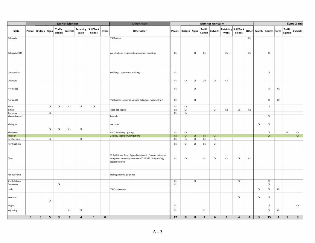
State
Colorado
Colorado 2 ITS
Connecticut
Delaware
Florida (1)
Florida (2)
IdahoIllinoisKentuckyMassachussetts
Michigan
MinnesotaMissouriNewMexico
NorthDakota
Ohio
Pennsylvania
SouthDakotaTennessee
Utah
Vermont
Virginia
Wyoming
Other Asset
Pavmt. Bridges SignsTraffic Signals
CulvertsRetaining Walls
Soil/Rock Slopes
Other Other Asset Pavmt. Bridges SignsTraffic Signals
CulvertsRetaining Walls
Soil/Rock Slopes
Other Pavmt. Bridges SignsTraffic Signals
Culverts
ITS Devices Ck
guardrail end treatments, pavement markings Ck Ck Ck Ck Ck Ck
Buildings ; pavement markings Ck Ck
Ck Ck Ck Off Ck Ck
Ck Ck Ck Ck
ITS Devices (cameras, vehicle detectors, toll gantries) Ck Ck Ck Ck
Ck Ck Ck Ck Ck Ck Ck CkFiber optic cable Ck Ck Ck Ck Ck Ck
Ck Ck CkTunnels Ck
Ck Ck Ck Ck
see notes Ck Ck
HMT, Roadway Lighting Ck Ck Ck Ck CkGeology sepcial investigations Ck Ck Ck Ck Ck Ck Ck
Ck Ck Ck Ck Ck Ck Ck
Ck Ck Ck Ck Ck
37 Additional Asset Types Monitored. Current active and integrated inventory consists of 737,845 (unique IDs)y assessed assets
Ck Ck Ck Ck Ck Ck Ck
drainage items, guide rail
Ck Ck Ck CkCk Ck Ck
ITS Components Ck Ck Ck
CkCk Ck Ck
Ck Ck Ck
Ck Ck Ck Ck Ck Ck
0 0 5 3 3 4 1 0 17 9 8 7 6 4 4 4 3 15 4 1
Do Not Monitor Monitor Annually Every 2 Year
3
A - 3

State
Colorado
Colorado 2 ITS
Connecticut
Delaware
Florida (1)
Florida (2)
IdahoIllinoisKentuckyMassachussetts
Michigan
MinnesotaMissouriNewMexico
NorthDakota
Ohio
Pennsylvania
SouthDakotaTennessee
Utah
Vermont
Virginia
Wyoming
Retaining Walls
Soil/Rock Slopes
Other Pavmt. Bridges SignsTraffic Signals
CulvertsRetaining Walls
Soil/Rock Slopes
Other Pavmt. Bridges SignsTraffic Signals
CulvertsRetaining Walls
Soil/Rock Slopes
Other Pavmt. Bridges Signs
NBI intervalsAge based condition, one time in 2013
Ck
Ck
Ck
Ck Ongoing process
Ck Ck Ck Ck 3 yr or as needed not sureexception is year to every 6months for critical condition structures
Ck Ck Ck Video logCk Ck Critical 1 yr; 2 yr
Ck Ck
PCR annually. Also capture road profile and video logs on each route every two years. 1/2 of state one year and 1/2 the next.
Ohio defines a structure as a length of 10' and not 20' per FHWA definitions
FHWA mandate of 5 year cycle for overhead signs. We capture ground mounted signs additionally
NHS annuallyinterval can be less for higher risk bridges
inventory
Ck CkCk
Ck Ck Ck Ck
Ck Ck NHS AnnuallyCurrently redeveloping inventory process
Ck Ck Ck Ck per NBIS per NBIS
Ck
3 2 3 0 0 4 6 4 4 1 0 0 0 0 1 0 1 0 0
rs Every 5 Years Every 10 Years
A - 4

State
Colorado
Colorado 2 ITS
Connecticut
Delaware
Florida (1)
Florida (2)
IdahoIllinoisKentuckyMassachussetts
Michigan
MinnesotaMissouriNewMexico
NorthDakota
Ohio
Pennsylvania
SouthDakotaTennessee
Utah
Vermont
Virginia
Wyoming
Traffic Signals Culverts Retaining Walls Soil/Rock Slopes OtherManual
monitoringDatalogger
Wired network
Wireless network
IoT device
Maintenance Teams Ck Ck Ck Ck
at problem locations in mountainous terrain or known rockfall areas, some advanced equipment is used to monitor these locations continuously
Asset managers assigned to each class of asset. CDOT wide available data through Online Transportation Information System (OTIS). This also feeds to centralized GIS ESRI driven platforms that can also be accessed by anyone in the organization
Ck
Age based condition, inventory updated as projects completed
Large culverts with Bridge Cycle, small culverts inventory under development
Building an inventory, 2008 partial inventory
Monitor select slopes periodically
Age based conditions; buildings ‐ one time inventory and condition in 2018
1. Asset Specific Groups Ck
Ck
Annually sample through Maintenance Rating Progream (MRP)
Annually sample through Maintenance Rating Progream (MRP)
Annually sample through Maintenance Rating Progream (MRP)
Maintenance, Pavement Design, State Materials Office Ck
Annually sample through Maintenance Rating Program (MRP)
Annually sample through Maintenance Rating Program (MRP)
Annually sample through Maintenance Rating Program (MRP)
Daily Maintenance, Pavement, District Production, Planning, Traffic Operations Ck
District Planners/Engineers CkProgram Development Ck Ck Ck CkMaintenance, Planning, Leadership, Budgets Ck
not sure Ck Ck Ck Ck
see notes Ck Ck
2015 inspection 2019 Slope study Varies Ampo, maint, planning Ck Ck Ck CkCritical 1 yr; 2 yr Bridge Related 2 yr Ongoing, weather Varies Ck Ck
Pavement Bureau, Bridge Bureau, Project development, Planning, CkAs needed based on activity and risk.
The information is used throughout the Department, but primarily by our Engineering Divisions.
Ck Ck Ck Ck
As needed.
Inspection depends on General Appraisal Rating (GA). Over 90,000 on record
Updates are annualDependent on Severity and Risk
Asset Dependent Inspections
Organizational Access, public, FWHA, Local Public Agencies, etc. Ck Ck Ck
inventoryinventory, no systematic monitoring
monitor high risk slopes every 4 years asset management, maintenance, planning, design
Operations and Planning and Engineering Ck CkMaintenance Division, Structures Division, Ck
ATSPM ‐ Very frequent Lots of internal uses by nearly every organization. Public facing as well. Ck Ck
Inventory exists, but am not sure how often it is monitored
20% Inventory Inspection Annually
Full inventory every 5th year
Asset Management, Performance Section, Maintenance Bureau/Districts Ck
load reting engineers and … Ck
Materials, Bridge, Traffic Ck Ck
22 8 7 7 2
2. Who Uses the inventory and/or monitoring information?
Other Period
Ck Ck
A - 5

State
Colorado
Colorado 2 ITS
Connecticut
Delaware
Florida (1)
Florida (2)
IdahoIllinoisKentuckyMassachussetts
Michigan
MinnesotaMissouriNewMexico
NorthDakota
Ohio
Pennsylvania
SouthDakotaTennessee
Utah
Vermont
Virginia
Wyoming
Other monitoring
Other Monitoring SpecificIndividual Computer
Central server
Online/cloud
GIS online system
UnfamiliarHeard of,
may consider
Currently evaluating
Have Used
Ck Ck Ck Ck
Ck
Fugro is contracted by CDOT to collect pavement condition on state highways. They have been recently extended to include video analytics that also collect other roadway and roadside assets on a yearly basis. Most recently, they have started to use a defects protocol, that Fugro then uses on their yearly data collection runs that identify if defects in the asset exist. Fugro uses their own data collection devices, equipment, and fleet vehicles using this equipment.
Ck Ck Ck Ck
Ck Ck Ck Ck Ck Ck Ck
Ck Ck Ck Ck
Ck Pavement is monitored by Rut, Crack and Ride Van. Ck Ck Ck Ck
Ck Pavement is monitored by IRI, Rut, Crack, & Ride Van Ck Ck Ck Ck Ck Ck Ck
Ck Ck Ck Ck CkCk Ck Ck Ck Ck
Ck Vehicles with sensors Ck Ck Ck Ck Ck CkCk Ck Ck Ck
Ck Ck Ck
Ck Agile Assets TAMS Software Ck Ck CkAran van and mobile retro‐reflective van Ck Ck Ck Ck Ck Ck
Ck Ck Ck Ck
Ck Ck Ck Ck
Ck ESRI Collector infrastructure (on‐prem) using data plans and GPS hand‐held units Ck Ck Ck Ck Ck Ck
automated pavement condition assessment Ck
Ck Ck Ck Ck CkCk Pavements by laser and HD photography Ck Ck
CkBridges, culverts,walls, slopes manually. Signals are fiber. signs, pavement marking are by Lidar, pavement is driven (manual)
Ck Ck Ck Ck
Ck ARAN Van for Pavement Ck Ck Ck Ck
Automated sensor data collection occurs on only a… Ck Ck Ck Ck
Ck Ck Ck
9 7 19 14 15 16 5 5 11 7
4. Data Storage 5. Use Dashboard platform?
6. Experience with IoT3. Monitoring
A - 6

State
Colorado
Colorado 2 ITS
Connecticut
Delaware
Florida (1)
Florida (2)
IdahoIllinoisKentuckyMassachussetts
Michigan
MinnesotaMissouriNewMexico
NorthDakota
Ohio
Pennsylvania
SouthDakotaTennessee
Utah
Vermont
Virginia
Wyoming
Currently evaluating for use example Used/In Use example
8,000 devices and 1,600 miles of fiber connecting our devices.
Using mobile IoT approach as described above for both asset inventory and asset condition on a yearly basis. In addition, the ITS/Traffic Operations division have 8,000 devices and 1,600 miles of fiber connecting our devices.
Isolated, site specific sensor applications in the past.
AI‐ITMS https://deldot.gov/Programs/itms/index.shtml?dc=projects
Testing connected automated use, Adaptive Signal Control Technology Toll pricing algorithms based congestion for managed lanes
Devices installed at a test site for lighting
Connected vehicle based technology and applications. US‐2 Cut River Bridge Pilot Deployment, Pilot CV Pavement Condition Data Collection,
Have email out to check with RTMC, signals folks; pendingCurrent Research project TR202006
Drive Ohio program added fiber optic, smart devices, vehicle sensors, etc. to allow organizations to test autonomous and connected vehicle technolgies in multiple corrirdors throughout the state
Developing an Enterprise Streaming Platform (ESP) to capture, analyze, and distribute real‐time data
Looking at auto devices. Connected vehicle (DSRC), ATSPM on signal system, blue tooth, radar, other passive data collection for traffic operations.
We are engaged in a research project with the University of Vermont to evaluate the feasibility of RFID technology for traffic sign and other asset monitoring.
A feasibility (research) project is underway to develop a wireless strain gauge for…
Connected vehicles included with sensors such as speed or signals.
6. Examples
A - 7

APPENDIX B - Vendor Information Sensors / IIoT Devices

Proposal for Large Structure monitoring
Missouri Department of Transportation
_Reach Further
B - 1

2
Project Overview
B - 2

OverviewThe Missouri Department of Transportation manages and maintains transportation assets such as bridges, retaining walls and overhead interstate sign. As of now for asset inspection, team visits in person to the respective asset and gather asset measurements (e.g. tilt/angle, crack length, skew etc.) along with the time. With the help of collected measurement and time information they can outline behavior of the asset for certain time period. To overcome this time consuming and tedious process they are looking for the IoT solution which can capture asset information and provide asset behavior visualization.
Avnet proposes to leverage IoTConnect Platform to develop this Remote monitoring solution. Using this solution, admin users will be able to monitor assets (e.g. Bridges, Retaining Walls, and Interstate overhead sign). Proposed solution will have back end admin panel for the MoDOT admin users. Admin will be able to manage assets, asset location, users, devices etc. using this panel. Admin will be able to view the inspection and maintenance information.
It will have web application for the transport officials, asset managers, and engineers. They will be able to monitor assets which are assigned to them. They will be able to view sensors data and KPIs of the asset. Using this panel they will be able to create maintenance schedule and assigned to respective team members.
It will have mobile application for the bridge inspector, maintenance team and consultant. Using this application they will be able to view scheduled maintenance and inspection. They will be able to update the maintenance andinspection information. This application helps them to navigate to asset information.B - 3
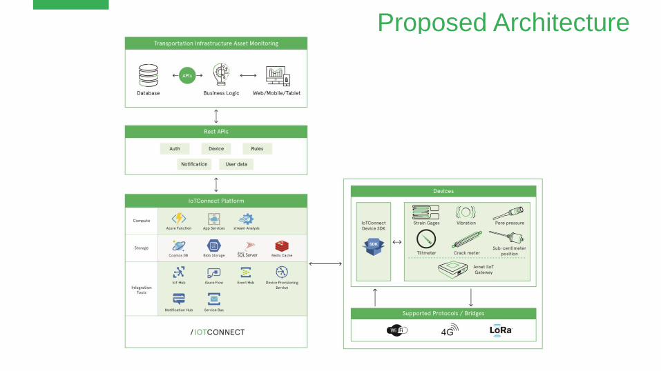
Proposed Architecture
B - 4

Internet
Cell Tower
GPS Satellite
Cell Modem
Strain GaugeVibration & Temp Sensor
Proximity Sensor Load Cells
Tilt Sensors
B - 5
System Overview

External Interfaces
Cellular & GPSAntennas
Solar Panel
Weather ProofEnclosurePower Bank/Battery
External PowerSupply
B - 6

7
Application FeaturesAvnet SmartEdge IIoT Gateway
B - 7

6/12/2020https://www.avnet.com/shop/us/products/avnet-engineering-services/avtse-rpi-iiotg-3074457345641639780
B - 8

Features
• SmartEdge gateway will be connected via Cellular to Avnet IoTConnect cloud platform
• Gateway will read Sensor data and publish to cloud
• Enclose the complete setup in weather proof enclosure
• Use external antenna due to the enclosure
• Updated power supply and battery to provide a safer operation
• Use solar panel to power the system with battery to recharge
• Cloud dashboard to show the information in layouts defined in the screens
B - 9

Avnet SmartEdge IIoT Gateway
B - 10
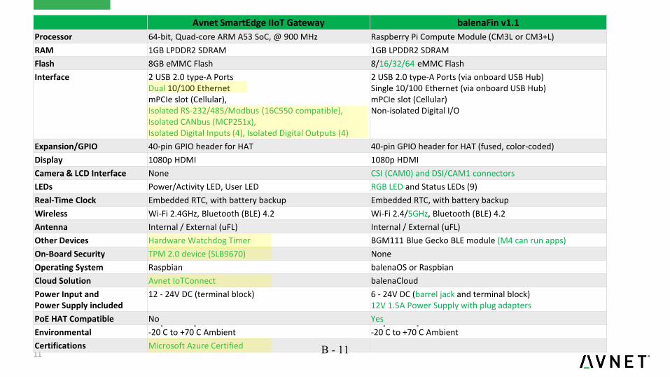
11
Avnet SmartEdge IIoT Gateway balenaFin v1.1
Processor 64-bit, Quad-core ARM A53 SoC, @ 900 MHz Raspberry Pi Compute Module (CM3L or CM3+L)
RAM 1GB LPDDR2 SDRAM 1GB LPDDR2 SDRAM
Flash 8GB eMMC Flash 8/16/32/64 eMMC Flash
Interface 2 USB 2.0 type-A PortsDual 10/100 EthernetmPCIe slot (Cellular),Isolated RS-232/485/Modbus (16C550 compatible), Isolated CANbus (MCP251x), Isolated Digital Inputs (4), Isolated Digital Outputs (4)
2 USB 2.0 type-A Ports (via onboard USB Hub)Single 10/100 Ethernet (via onboard USB Hub)mPCIe slot (Cellular)Non-isolated Digital I/O
Expansion/GPIO 40-pin GPIO header for HAT 40-pin GPIO header for HAT (fused, color-coded)
Display 1080p HDMI 1080p HDMI
Camera & LCD Interface None CSI (CAM0) and DSI/CAM1 connectors
LEDs Power/Activity LED, User LED RGB LED and Status LEDs (9)
Real-Time Clock Embedded RTC, with battery backup Embedded RTC, with battery backup
Wireless Wi-Fi 2.4GHz, Bluetooth (BLE) 4.2 Wi-Fi 2.4/5GHz, Bluetooth (BLE) 4.2
Antenna Internal / External (uFL) Internal / External (uFL)
Other Devices Hardware Watchdog Timer BGM111 Blue Gecko BLE module (M4 can run apps)
On-Board Security TPM 2.0 device (SLB9670) None
Operating System Raspbian balenaOS or Raspbian
Cloud Solution Avnet IoTConnect balenaCloud
Power Input andPower Supply included
12 - 24V DC (terminal block) 6 - 24V DC (barrel jack and terminal block) 12V 1.5A Power Supply with plug adapters
PoE HAT Compatible No Yes
Environmental -20°C to +70
°C Ambient -20
°C to +70
°C Ambient
Certifications Microsoft Azure Certified B - 11

Dashboard Mock-up
B - 12

13 B - 13

14
Application Features
B - 14

Application FeaturesBack End Interface for - Transportation Infrastructure Monitoring (Admin user)
• Login, Remember Me, Forgot Password• User will be able to Sign in to the application; using their valid credentials.• Option for "Remember Me" and "Forgot Password"
• Dashboard• Statistics like no. of bridges, no. of retaining walls, no. of Interstate overhead sign, required maintenance, running
maintenance • Map view – (Showcase assets using map view)• Important KPIs [i.e. Service life graph, Condition category graph (Critical, Moderate, Minor), Safety Graph,
Reliability Graph]• Alerts
• Manage Location• Create Location – User will be able to create new location using this section. User will be able add information such
as:• Location Name• Location Details• Manage zones – User will be able to create and manage zone for the location. User will be able to add
information such as: Zone Name, and Latitude, LongitudeB - 15

Application Features• Manage Device Kit
• Create Device Kit – It allows user to create or add device kit using this section. User will be able to add information such as:
• Device ID• Unique ID• Mapping with location and zone • Manage Sensors – It allows user to manage sensors associated with the kit.
• Edit / Delete – It allows user to edit/delete created device kit.• Device Kit – list View• It allows user to view list of created device kit. By clicking on any device kit, it allows user to view device kit
details.• View Device Kit Details – It allows user to view selected device kit details.
• Information – User will be able to view the device kit information such as device id, unique id and other device kit property.
• Sensors – User will be able to view list of sensors associated with the selected device kit. • User will be able to view the latest value of the sensor and can view the graph for the selected sensor.• User will be able to view live telemetry graph for the selected sensor.
• Notification – User will be able to view notifications generated for selected device.• Historical Graph – User will be able to view historical graph for selected device.
B - 16

Application Features• Manage Asset Type
• Create Asset type – It allows user to create new asset type. User will be able to add information such as:• Asset type Name (E.g. Bridge, Retaining wall, Interstate Overhead Sign)• Description• Image
• Edit / Delete Asset – It allows user to edit/ delete created asset type.• Asset type – List view
• It allows user to view list of create asset type.• Manage Asset
• Create Asset (Bridge, Retaining walls, overhead interstate sign) – It allows user to create new asset using this section. User will be able to add information such as:
• Asset Name• Location• Asset Type• Device Kit Mapping – Single asset can be mapped with more than one device kit.• Description
• Edit/ Delete Asset – It allows user to edit/delete created asset.• Asset List view - It allows user to view the list of created assets. By clicking on any asset from the list view, user will
be redirected to asset details.B - 17

Application Features• Asset Detail (Dashboard)
• View asset details – Showcase asset information such as asset name, location, asset status, latest sensor value, traffic count, No. of alerts etc.
• Deflection Graph, Strain Graph• Safety graph – (Safety index vs. Time)• Bridge Health Monitoring• Telemetry data – ( Based on selected asset, showcase real time sensor data of vibration, tilt, crack , strain, pore,
temperature)• Notifications (It displays notification/alerts related to asset displacement, crack, load, vibration, pore pressure)
• Manage Users• Create Users – User will be able to create new system user using this section. User will be able to add information
such as:• Name• Email• Contact Number• Department• Assign Role to user• Mapping with Asset
• Edit /Delete User – User will be able to edit/delete created user.• User List view – User will be able to view list of created user from this section.B - 18

Application Features• Manage Roles
• Create Role (e.g. Transportation Officials, Managers, Bridge Engineers, Bridge Inspectors, Maintenance Team, and Consultant) – User will be able to create new role and configure permission for the role.
• Edit/ Delete Role – User will be able to edit/ delete created role.• Role List View – User will be able to view create role and associated permission using this section.
• Manage Rules• Create Rule – User will be able to create new rule • Edit/ Delete Rule - User will be able to edit/ delete created rule.• View Rule – User will be able to view list of all the rules.
• Maintenance / Inspection• View Maintenance/ Inspection - User will be able to view created maintenance and inspection records.• Schedule Maintenance / Inspection – User will be able to create new maintenance/ inspection and assign to
respective user (user role).• Edit/ Delete – User will be able to edit/delete maintenance/inspection information using this section.
• Notification• User will be able to view all the notification generated as per the configured rule for assets. (It displays
notification/alerts related to asset displacement, crack, load, vibration, pore pressure) • Profile
• User will be able to view and update personal information. B - 19

Application FeaturesFront end Web Application for - Transportation Officials/ Managers/ Bridge Engineers
• Login, Remember Me, Forgot Password• User will be able to Sign in to the application; using their valid credentials.• Option for "Remember Me" and "Forgot Password"
• Dashboard – User will be able to view overall insights of the assigned assets • Statistics like no. of bridges, no. of retaining walls, no. of Interstate overhead sign, required maintenance, running
maintenance • Map view – (Showcase installed assets using map)• Important KPIs [i.e. Condition graph (Critical, Moderate, Minor), Safety Graph, Reliability Graph]• Alerts
• Asset Card View • Asset Information – User will be able to view asset information such as asset name, location, asset status, asset
condition, alerts etc. • Asset Details
• User will be able to view following information on asset detail screen:• Asset Name• Asset Location• Asset Status
•
B - 20

Application Features• Asset Details
• Statistics – User will be able to view important statistics and KPIs – (Asset condition graph, Asset service graph, Failure Rate, Alerts, etc.)
• Telemetry Graph ( User will be able to view real time graph of the sensor)• Scheduled Maintenance/inspection list• Alerts (It displays alerts related to displacement, crack, load, vibration, pore pressure)
• Schedule Maintenance / Inspection• User will be able to schedule new maintenance/inspection using this section. User will be able to add asset
information, maintenance/inspection notes etc. User will be able to assign maintenance/inspection to specific team member (Bridge Inspector, Maintenance Team, Consultant) for the inspection and maintenance.
• View Maintenance/Inspection List – User will be able to view scheduled maintenance/inspection records in list view.• Edit/ Delete Maintenance – User will be able to edit/delete created maintenance/ inspection.
• Profile
B - 21

Application FeaturesFront end Application (Mobile/ Tablet) for - Bridge Inspector / Maintenance Team / Consultant
• Login, Remember Me, Forgot Password• User will be able to Sign in to the application; using their valid credentials.• Option for "Remember Me" and "Forgot Password"
• Dashboard – User will be able to view insights of the assigned assets • Statistics like Assigned Maintenance/ inspection, Pending Maintenance/ inspection, Completed
Maintenance/inspection, Alerts • Alerts List (Related to assigned asset and task)
• Maintenance & Inspection List• User will be able to view assigned maintenance and inspection records in list view.• User will be able to view the asset name, asset location, etc.
• Maintenance & Inspection Details• User will be able to view the asset name, asset location, maintenance detail etc.• User will be able to upload photos of the asset.• User will be able to update inspection and maintenance information.
• Profile
B - 22

23
Cost
B - 23

31
Guiding today’s ideas into tomorrow’s technology
We help you reach further B - 31

Summary of Resensys capabilities To meet structural monitoring needs of Missouri Department of Transportation (MoDOT), various types of Resensys wireless sensor nodes (known as SenSpot) will be used for monitoring strain, displacement, acceleration (vibration), and tilt (orientation). In addition, Resensys SeniMax gateway will be used for logging data and remote communication. SeniMax streams data to a secure cloud server. The data in the cloud is backed up every three hours. Resensys SenScope will be used for various purposes including data visualization, alert management, and data export purposes. In addition, SenScope will be used for various types of analysis, including data regression, statistical analysis, and Fast Fourier Transformation (FFT) analysis of vibration (acceleration) data. Table 1 provides a summary of each instrument and their specifications are given. Table1: proposed instrumentation to be used in the current project
Instrument or tool Specifications
Strain SenSpot Resolution: 1.0 microstrain; Full range: ±4000 microstrain Options: rosette, axial strain, and shear strain measurement Temperature compensation: YES Power: 10-year battery life using built in non-rechargeable battery Additional sensing: temperature, battery voltage, wireless signal strength
(RSSI)
Displacement SenSpot
Resolution: 0.1mil (2.5 micrometers) , repeatability: 0.4mil (10 micrometer) Full range options: .5in, 10in, 2.0in, 3.0in, 4.0in, 5.0in, 6.0in, 12.0in Power: 10-year battery life using built in non-rechargeable battery Additional sensing: temperature, battery voltage, wireless signal strength
(RSSI)
Vibration SenSpot Resolution: 0.1mg or 1.0mg Full range options: ±2g, ±4g, ±8g, user selectable Power: 10-year battery life using built in non-rechargeable battery Additional sensing: temperature, battery voltage, wireless signal strength
(RSSI)
Hi-Precision Tilt SenSpot
Resolution: 0.00016 degrees (0.5 arc seconds) Full range options: ±1degrees, ±10 degrees, single axis and dual axis options Power: 10-year battery life using built in non-rechargeable battery Additional sensing: temperature, battery voltage, wireless signal strength
(RSSI)
SeniMax gateway and data logger
Power: solar-rechargeable battery Coverage area: 0.6 miles radius (can be extended via signal repeaters) Reserved power: minimum of three weeks of operation in absence of solar
charging Redundancy: fully redundant solar charges, charging systems, batteries. Synchronization precision: 0.1 millisecond Communication capability: IEEE802.15,4 (communication with SenSpots), and
cellular for communication with secure cloud server Cellular compatibility: compatible with GPRS, HSPA, HSPA+, 3G/4G/LTE,
compatible with T-Mobile, AT&T and Verizon Wireless cellular networks.
B - 32

Additional sensing: temperature, battery voltages, charge currents, signal strength
SenScope software Communication: Secure (SSL) communication with secure cloud server User: access controlled administrator and regular users, unlimited number of
users Alert: various types of alerts based on threshold or comparative analysis Alert administration: text message, email Analysis types: thermal analysis, statistical analysis, comparative (regression)
analysis, FFT Data export tools: export in Excel, txt, XML formats Data filtering tools: filter tools for outlier removal, low pass (smoothing)
filtering, data trend calculation
The next sections describe how variations of the instruments and analysis tools listed in Table 3.1 will be used to address specific bridge monitoring needs of MoDOT.. 1. Strain monitoring For strain monitoring, Resensys’ wireless strain SenSpot sensors will be used. Standard SenSpot sensors for monitoring strain in steel members have a resolution of 1.0 microstrain while the full scale strain monitoring is ±4000 microstrain. Both range and resolution are customizable if desired. Once installed, the devices are designed to conduct 10 years of monitoring using a ½AA prime (non-rechargeable) lithium ion battery. The complete wireless operation and long term monitoring make SenSpot strain sensors an ideal solution for monitoring needs of the current project. Figure 1 shows a Resensys strain SenSpot sensor installed on a steel truss chord. Figure 2 shows a 38-month data of strain readings reported by a SenSpot attached to a Maryland bridge.
Figure 1: Resensys strain SenSpot sensor installed on a steel truss chord
B - 33

Figure 2: Resensys strain SenSpot sensor measurements over a course of 37-month continuous monitoring on a US-40 bridge girder (Data from October 2013 – Nov 2016).
2. Tilt and Orientation monitoring For monitoring orientation (tilt, inclination), Resensys’ wireless precision tilt SenSpot sensors will be used. Similar to strain SenSpot sensors, the orientation SenSpot sensors have a battery life of 10 years, making them ideal for long term monitoring for settling, foundation instability, deflection, deformation, etc. High resolution tilt SenSpot sensors have a resolution of 0.00016 degrees (0.5 arc seconds), and they have a linear full range measurement of ±1.0 degrees or ±10 degrees. Figure 3 shows an example of high precision tilt SenSpot sensor used to monitor bearing (left side picture) pier deflection and deformation (right side picture) on a Maryland bridge. Continuous monitoring of the piers in that project has been in place since September 2014, more than two years at the time of this proposal. Figure 4 shows a sample 26-month high precision tilt data from the mentioned piers.
Figure 3: High precision tilt SenSpot sensors monitoring bridge's rocker bearing rotation (left) and pier movements (right)
B - 34

Figure 4: Resensys tilt SenSpot sensor measurements over a course of 26 months continuous monitoring of rocker bearing movement (Tilt data from October 2014 until November 2016).
3. Displacement monitoring Resensys’ wireless displacement SenSpot sensors have a repeatability of 10 micrometers (or about 0.4mil) with a resolution of 2.5 micrometer (0.1mil). Different options are available for the full scale measurement in Resensys displacement SenSpot sensors. The options are 0.5-inch, 1-inch, 2-inch, 3-in, 4-inch, 5-inch, 6-inch, and 12-inch. Figure 5 shows an example of a Resensys displacement SenSpot sensor. The data in Figure 6 shows the 2.5-year displacement on an expansion joint of a bridge in Canada (March 2014 until November 2016).
B - 35
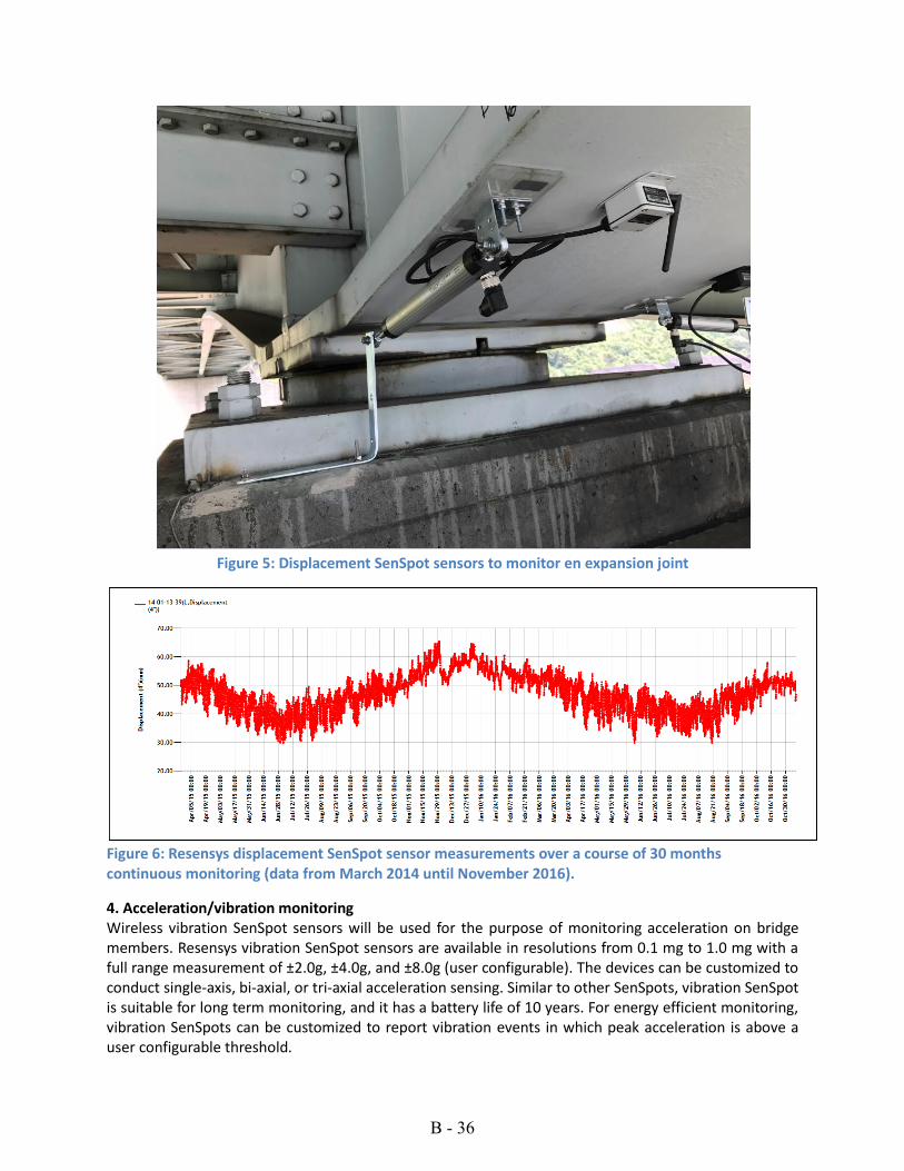
Figure 5: Displacement SenSpot sensors to monitor en expansion joint
Figure 6: Resensys displacement SenSpot sensor measurements over a course of 30 months continuous monitoring (data from March 2014 until November 2016).
4. Acceleration/vibration monitoring Wireless vibration SenSpot sensors will be used for the purpose of monitoring acceleration on bridge members. Resensys vibration SenSpot sensors are available in resolutions from 0.1 mg to 1.0 mg with a full range measurement of ±2.0g, ±4.0g, and ±8.0g (user configurable). The devices can be customized to conduct single-axis, bi-axial, or tri-axial acceleration sensing. Similar to other SenSpots, vibration SenSpot is suitable for long term monitoring, and it has a battery life of 10 years. For energy efficient monitoring, vibration SenSpots can be customized to report vibration events in which peak acceleration is above a user configurable threshold.
B - 36

Figure 7 shows a sample of vibration SenSpot installed on a bridge in Indonesia. Figure 8 shows detection of an earthquake on June 7, 2016 at 15:15pm EST (19:15 UTC Time).
Figure 7: Acceleration SenSpot sensor installed on a bridge in Indonesia
Figure 8: Acceleration SenSpot sensors detected an earthquake in Indonesia on June 7, 2016 at 3:15pm, EST (http://www.ndtv.com/world-news/6-3-magnitude-earthquake-hits-off-indonesia-no-tsunami-alert-1416611)
5. SeniMax Data Logger and Gateway Resensys SeniMax is a low power (only 20 milliWatts average power, 5.0 Watts peak power) and high performance data collector and remote communication gateway. SeniMax is energy self-sufficient and solar powered. SeniMax is designed with enough battery backup, so it can operate for more than three weeks in complete absence of light. SeniMax uses cellular data services to transmit bundles of data from SenSpot sensors to a cloud database system. In addition, SeniMax has capability of logging data locally for a minimum of two months in case that it loses cellular communication with cloud database server. The long term local data capability makes SeniMax a suitable choice for the bridges where cellular data coverage is weak or unreliable (e.g., monitoring bridges in remote areas). Logged data from SeniMax can
B - 37

be manually downloaded over a secured wireless link, in case that cellular data coverage is not available at the installation site. SeniMax synchronizes measurements of all SenSpot sensors installed on different locations with a precision of 0.1 milliseconds. This is a useful feature for comparing the measurements of SenSpot sensors at different locations at the same time which can later be analyzed by SenScope software’s analysis tools. SeniMax communicates with SenSpot sensors using IEEE802.15.4 (Zigbee) protocol. Additionally, SeniMax has capability to communicate the aggregated data of SenSpot sensors to any remote data center using cellular data services (GPRS, CDMA, HSPA, 3G/4G/LTE etc). SeniMax is compatible with the US cellular service providers, including AT&T, T-Mobile and Verizon Wireless. Based on the coverage of cellular service provider at the location of each bridge, the best provider will be chosen to ensure highest reliability of operation. SeniMax gateway is IP67, weatherproof and protected against rain, snow, and UV exposure. It can also withstand immersion of up to 3.0ft. Its light weight (3.3 lbs) makes installation of SeniMax very fast and easy. A single SeniMax can cover up to 250 SenSpot sensors in its communication range. The communication range is 0.62mile (1.0km) in free space which can be extended by using Resensys Repeaters which bounce the transmitted packets for another 0.62mile. There is no limitation in number of Repeaters that can extend the range of SeniMax which makes the Resensys system very reliable and flexible for long bridges. Currently Resensys SeniMax gateways have been deployed on massive superstructures such as a 10,000-foot bridge in Virginia (some of them are shown in Figure 9).
Figure 9: Installation of Solar Powered SeniMax Gateway and Repeaters installed on Bridges
For condition awareness and management, SeniMax gateways report their battery voltage, charging current from their solar panels, signal strength of cellular network, and temperature. These conditions are monitored to ensure the system reliably streams data into the cloud servers. Figure 10 shows the yearly charging current of solar panel and the voltage of a SeniMax as an example.
B - 38

Figure 10: Sample of voltage and charge current measurement of a SeniMax over a course of 1 year
(Nov 2015- Nov 2016)
As a final note, it must be added that each SeniMax gateways have two independent (redundant) solar chargers, batteries, and battery monitoring systems. The redundant power supply makes SeniMax reliable with very little down time.
B - 39

6. SenScope: web based data hosting, analysis, management, and alert generation Resensys offers SenScope software as a web based and standalone software package for data analysis, management, and alert generation. SenScope software package has built-in features that meet all the requirements of MoDOT. The summary of SenScope features is given in Table 2. Table 2: Summary of Resensys SenScope Software Package Features
Item Available feature(s) in SenScope
Security Using a secure “SSL” connection, each user can connect to
highly secure cloud database of Resensys.
Storage method Data is stored in Resensys’ secure cloud servers and backed up
every 3 hours on Amazon AWS cloud servers.
Number of users No user-limit number in the software.
Data Export Data will be exported to Excel, TXT, CSV, and XML formats.
Data Display and
Signal filter
SenScope provides visualization of data in charts with tools
such as
Filtering the graphs (smoothing) and extracting the
trends
Removing the trends
Removing the outliers
Showing the spikes (transients, e,g, caused by passing
trucks),
Down-sampling of data
Modifying chart formats, types, saving and exporting
graphs
Process data SenScope provides sophisticated tools for
Statistical analysis,
Comparative (regression) analysis
Spectral analysis (FFT)
Alert notification SenScope offers three types of alerts:
Threshold-based alerts,
Regression based alerts,
Disconnection alerts (communication error)
Alert administration is conducted through text message and
email notifications.
Remotely
configurable
thresholds
SenScope provides interface to change event detection
thresholds, sampling interval, and transmission interval for
SenSpot sensors.
Various capabilities and tools in SenScope are discussed below. Access to cloud data. Each user will have a unique user account and using a secure connection (SSL) only can access to the devices that he/she is assigned to. There will be two different levels of users:
B - 40

Standard users can watch the data of listed devices in their account, they can export the data to Excel, xml or text formats and they can use data analysis tools on the data. Administrator users have all the privileges of a standard user. In addition, they have access to set the alerts, calibration information, and registration of devices. They can and also perform remote configuration operation on devices. The data is stored in Resensys’ secure cloud is backed up every 3 hours. In addition, an Amazon AWS cloud server is used as a secondary backup. The graphs in the following Figures show example screen shots of Resensys SenScope. The graph in Figure 10 shows the main console of SenScope, showing how various monitoring sites can be selected from a drop-down menu (top left side). In the system all instruments installed on a given structure or facility are listed under a group or “Site”, and each site is characterized by a unique Site ID. By selecting a given Site from the drop down menu, all instruments in that side are listed and data from each instrument can be displayed, analyzed, or exported using the software. Also, when many various users of the system can independently granted access to data of each Site. The screenshot in Figure 12 shows example of how data of various data from different wireless instruments can be visualized on a graph. In this case, the data shows strain of three wireless devices installed on girders of a bridge.
Figure 11: The main console of Resensys SenScope
B - 41

B - 42
Figure 12: Data display function in SenScope. Data can be displayed for any length of time.

Resensys LLC TEL: 301-395-3892 email: [email protected] www.resensys.com
SeniMax™ Data Logger and Gateway Ultra-Low Power Sensing and Remote Wireless Communications
Features Ultra low power: consuming only 20mW (average
power) , 5.0 Watts peak power
Energy self sufficient: powered by ambient light; when battery fully charged, operates more than three weeks in absence of light
Wireless protocols:
- IEEE 802.15.4 (communication with SenSpot™ sensors) - CDMA, GPRS, HSPA+, Ethernet, WIFI (communication with remote servers)
Ingress protection: IP67, weatherproof and protected against rain, snow, and UV exposure
Local logging: minimum of two month in case of cellular data service error or unavailability
Coverage: up to 250 SenSpot™ sensors
Synchronization precision: 0.1 millisecond
Coverage area: 0.6 miles radius (can be extended via signal repeaters)
Lightweight: 3.3 lbs (1.5Kg)
Applications Resensys SeniMax is a low power and high performance data collector and remote communication device. SeniMax communicates with SenSpot sensors using IEEE802.15.4 protocol. Additionally SeniMax has capability to communicate the aggregated data of SenSpot sensors to any remote data center using Ethernet, WIFI or cellular data services.
In a remote measurement and monitoring architecture, SeniMax is the gateway for transmitting data of SenSpot sensors to a remote monitoring center. SeniMax receives data of Resensys SenSpot sensors using its wireless IEEE802.15.4 interface, and communicates it to a remote server using cellular data services (GPRS, CDMA, HSPA, etc). A single SeniMax can cover up to 250 SenSpot sensors in its communication range.
SeniMax is ideal solution in applications of distributed sensing and data acquisition where there is no access to main power or communication infrastructures. Particular applications include: Structural integrity monitoring for highway bridges, construction projects, pipelines, etc.
B - 43

Resensys LLC TEL: 301-395-3892 email: [email protected] www.resensys.com
Dimensions (in inch)
B - 44

Resensys LLC TEL: 301-395-3892 email: [email protected] www.resensys.com
SenSpot™ Strain Gauge Ultra-Low Power Precision Sensing & Wireless Communication
Typical Applications Structural Health Monitoring (Bridges, Build-
ings, Airplanes, Cranes, Platforms, Machinery, etc.)
Features & Benefits Long lifetime (minimum expected life without
battery replacement 10 years)
Lightweight, about 147 gr o Wireless transmitter: 120 gr o Cable (1ft): 10 gr o Strain sensing element: 17 gr
Easy mounting o Self-adhesive, no drilling is required (e.g.
steel) o Flange-mount, drilling is required (e.g. con-
crete)
Quick installation, 1-2 minutes
Accurate: 1-µStrain resolution
Full range: ±4000 µStrain
Wide working temperature: -40 to +150°F (-40 to +65°C)
Long communication range: 1.0km free space
Small size: o Wireless transmitter: 1.96” x 1.96” x 1.34” o Displacement sensor: 4.30”x1.30”x0.35”
Complementary sensing: temperature, acceler-ation, battery voltage, etc.
Ingress Protection: IP65, weatherproof and protected against rain, snow, and UV exposure
Sensing probe options: Full bridge, half bridge, rosette strain gauge (both steel and concrete)
Description SenSpot™ provides an easy to install, scalable solution for distributed structural integrity monitor-ing. SenSpot™ strain gauge uses Resensys’s accurate measurement, large-scale sensing, wireless syn-chronization, and ultra-energy efficient wireless communication.
SenSpot™ is designed to operate maintenance-free for more than a decade. SenSpot™ does not need calibration, battery replacement, or other mainte-nance after installation. Due to small size and lightweight, adhesive-mount SenSpot™ sensors can be applied easily to as many critical spots on a structure as needed, with minimal installation effort.
B - 45
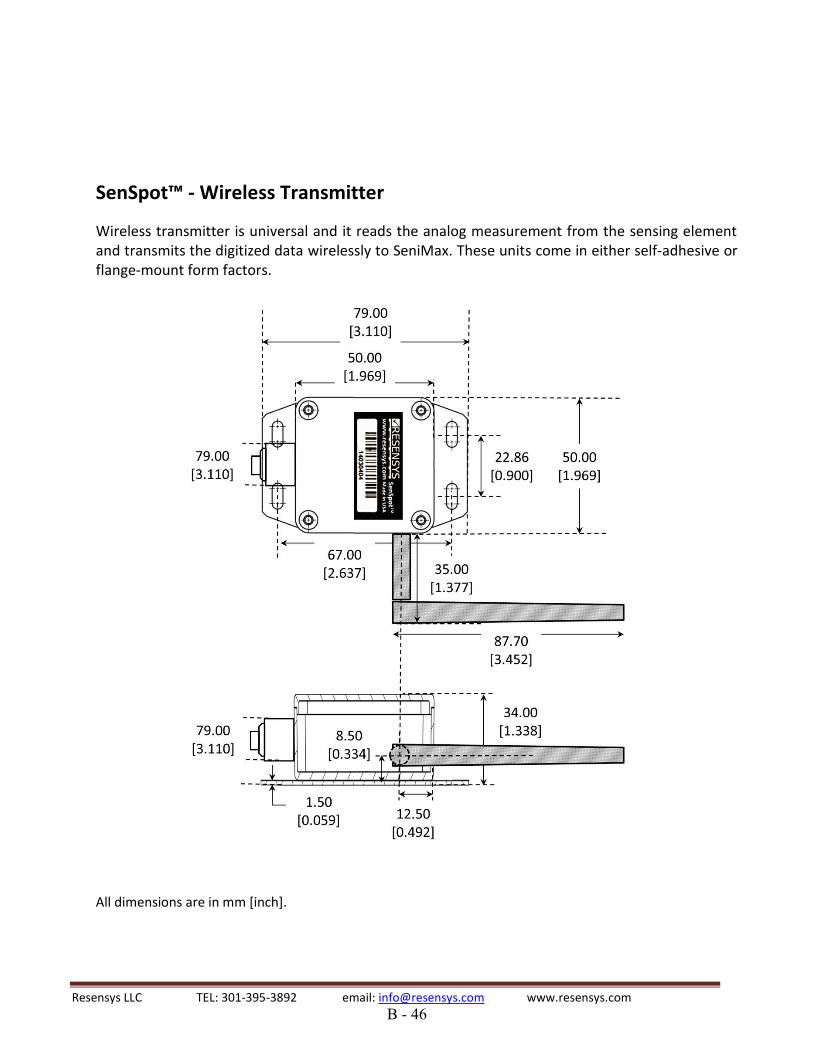
Resensys LLC TEL: 301-395-3892 email: [email protected] www.resensys.com
SenSpot™ - Wireless Transmitter
Wireless transmitter is universal and it reads the analog measurement from the sensing element and transmits the digitized data wirelessly to SeniMax. These units come in either self-adhesive or flange-mount form factors.
B - 46
All dimensions are in mm [inch].
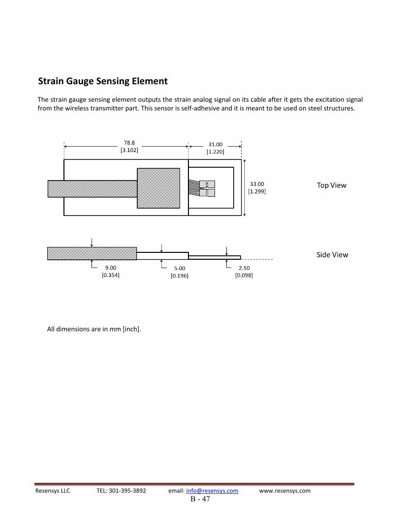
Resensys LLC TEL: 301-395-3892 email: [email protected] www.resensys.com
Strain Gauge Sensing Element
The strain gauge sensing element outputs the strain analog signal on its cable after it gets the excitation signal from the wireless transmitter part. This sensor is self-adhesive and it is meant to be used on steel structures.
All dimensions are in mm [inch].
B - 47

Resensys LLC TEL: 301-395-3892 email: [email protected] www.resensys.com
SenSpot™ Displacement Meter Ultra-Low Power Precision Sensing & Wireless Communication
Typical Applications Bridge health monitoring General structural integrity monitoring
(buildings, dams, tunnels, etc.)
Features & Benefits Long lifetime (battery life of 10 years)
Wireless communication (IEEE 802.15.4)
Lightweight (about 245 gr) o Wireless transmitter: 4.2 ounces (120 gr) o Cable (1ft): 0.35 ounces (10 gr) o Displacement sensing element: 4.0 ounces (
115 gr)
Adjustable sampling interval
Resolution: 2.5µm (0.1mil)
Repeatability: 10µm (0.4mil)
Full range: .5in, 1.0in, 2.0in, 3.0in, 4.0in, 5.0in, 6.0in, 12.0in
Working temperature: -40 to +150°F (-40 to +65°C)
Long communication range: 0.62mile (1.0km) free space
Ingress Protection: IP65, weatherproof and protected against rain, snow, and UV exposure
Small size: o Wireless transmitter: 1.96” x 1.96” x 1.34” o Displacement sensing element: 6.25”x0.9”
Power source: replaceable lithium-ion battery
Description
SenSpot™ provides an easy to install, scalable solution for distributed structural integrity monitoring. Resensys SenSpot™ technology offers a high performance method for large-scale sensing, wireless synchronization, and ultra-energy efficient wireless communication.
SenSpot™ is designed to operate maintenance-free for more than a decade. After installation, SenSpot™ does not need calibration, battery replacement, or any other maintenance during its entire service life. Due to small size and lightweight, adhesive-mount SenSpot™ sensors can be applied easily to as many critical spots on a structure as needed, with minimal installation effort.
SenSpot™ displacement meter can be used for measurement and progress of the existing cracks in a structure. This device has a sliding element which moves with displacement of structure or growth of a crack.
B - 48

Resensys LLC TEL: 301-395-3892 email: [email protected] www.resensys.com
SenSpot™ - Wireless Transmitter
Wireless transmitter is universal and it reads the analog measurement from the sensing element and transmits the digitized data wirelessly to SeniMax. These units come in either self-adhesive or flange-mount form factors.
All dimensions are in mm [inch].
B - 49

Resensys LLC TEL: 301-395-3892 email: [email protected] www.resensys.com
Displacement sensing element
All dimensions are in mm [inch].
B - 50
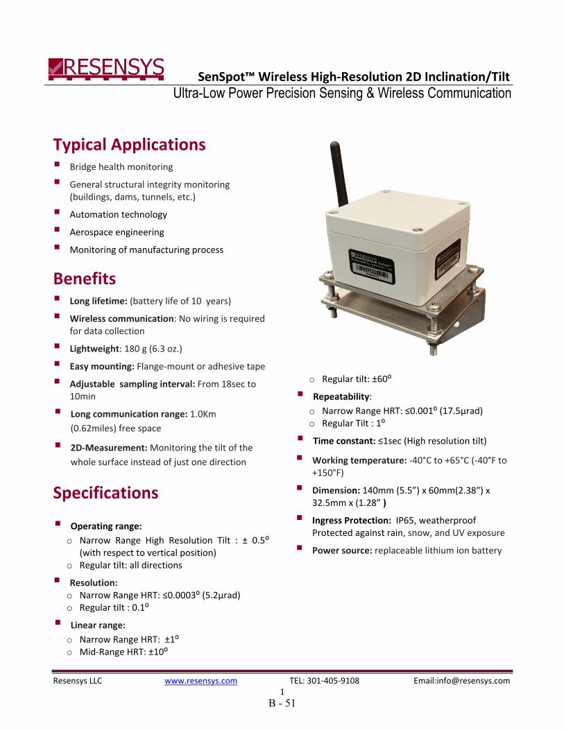
Resensys LLC www.resensys.com TEL: 301-405-9108 Email:[email protected] 1
SenSpot™ Wireless High-Resolution 2D Inclination/Tilt Ultra-Low Power Precision Sensing & Wireless Communication
Typical Applications Bridge health monitoring General structural integrity monitoring
(buildings, dams, tunnels, etc.)
Automation technology Aerospace engineering Monitoring of manufacturing process
Benefits Long lifetime: (battery life of 10 years)
Wireless communication: No wiring is required for data collection
Lightweight: 180 g (6.3 oz.)
Easy mounting: Flange-mount or adhesive tape
Adjustable sampling interval: From 18sec to 10min
Long communication range: 1.0Km
(0.62miles) free space
2D-Measurement: Monitoring the tilt of the
whole surface instead of just one direction
Specifications
Operating range:
o Narrow Range High Resolution Tilt : ± 0.5⁰ (with respect to vertical position)
o Regular tilt: all directions
Resolution: o Narrow Range HRT: ≤0.0003⁰ (5.2µrad) o Regular tilt : 0.1⁰
Linear range:
o Narrow Range HRT: ±1⁰ o Mid-Range HRT: ±10⁰
o Regular tilt: ±60⁰
Repeatability:
o Narrow Range HRT: ≤0.001⁰ (17.5µrad) o Regular Tilt : 1⁰
Time constant: ≤1sec (High resolution tilt)
Working temperature: -40°C to +65°C (-40°F to +150°F)
Dimension: 140mm (5.5”) x 60mm(2.38″) x 32.5mm x (1.28” )
Ingress Protection: IP65, weatherproof Protected against rain, snow, and UV exposure
Power source: replaceable lithium ion battery
B - 51

Resensys LLC www.resensys.com TEL: 301-405-9108 Email:[email protected] 2
Description
SenSpot™ provides an easy to install, scalable solution for distributed structural integrity monitoring. SenSpot™ inclination/tilt uses Resensys’s proprietary technology for reliable and accurate measurement, large-scale sensing, wireless synchronization, and ultra-energy efficient wireless communication.
SenSpot™ is designed to operate maintenance-free for more than a decade. After installation, SenSpot™ does not need calibration, battery replacement, or any other maintenance for at least 10 years. Due to small size and lightweight, SenSpot™ sensors can be applied easily to as many critical spots on a structure as needed, with minimal installation effort.
As a part of the Resensys solution for integrity monitoring system, SenSpot™ inclination/tilt can be used to monitor the smallest movements of structural components such as piers, decks, bearings on a highway bridge. In addition, SenSpot™ inclination/tilt monitors changes in these quantities as the structure expands or contracts as a result of temperature variations. In addition to bridges, SenSpot™ inclination/tilt can be used in a variety of other structures. Examples include buildings, dams, etc.
Installation and Dimensions
The tilt sensors are built-in the SenSpot™ unit. The measured value is transmitted wirelessly to SeniMax. It is recommended to install the SenSpot™ with screws and anchors through the flange. It is possible to install the SenSpotTM with VHB tape on smooth surfaces. However, since adhesive tape is soft its shape and thickness may change due to the temperature and humidity variations. This in turn, degrades the accuracy of high-resolution tilt measurement. High-resolution tilt measurement is ONLY valid in the horizontal direction (please see Figure 3).For detailed explanation about the installation of SenSpotTM , please see 2D HRT SenSpotTM instruction manual. Figure 2 shows the box dimensions and figure 3 shows Pitch and Roll orientation and direction. Please remember, when the antenna side is raised, both Pitch and Roll are increased. As a result, it is pretty easy to keep in mind the direction of change of Pitch and Roll.
87
.70
[3.4
5]
35.00
[1.38]
Fig2: 2D HRT SenSpotTM
Dimensions. All measurements are in mm [inch]
B - 52

Resensys LLC www.resensys.com TEL: 301-405-9108 Email:[email protected] 3
Direction Diagram
Pitch Roll
+ - - +
SECTION B-B g END VIEW
Fig3: Pitch and Roll orientations
B - 53

Resensys LLC www.resensys.com TEL: 301-405-9108 Email:[email protected] 1
SenSpot™ Wireless 1D/3D Vibration Ultra-Low Power Precision Sensing & Wireless Communication
Typical Applications Bridge health monitoring
General structural integrity monitoring (build-ings, dams, tunnels, levies, etc.)
Features & Benefits Long lifetime (battery life of 10 years)
Wireless communication (IEEE 802.15.4)
Lightweight, about 120 grams
Easy mounting o Self-adhesive, no drilling is required (e.g.
steel) o Flange-mount, drilling is required (e.g. con-
crete)
Quick installation, 1-2 minutes
Adjustable sampling interval: 0-200 samples per second
Adjustable sensitivity threshold: From 8mg to 255mg. Threshold can also be set adaptive to limit number of events
Adjustable Transmitting interval
Full range: ±2g (“g” is the acceleration of gravity)
Resolution: 4 ug
Noise Level:
o X & Y &Z Direction: 25μg √𝐻𝑧⁄
Working temperature: -40°C to +65°C (-40 to +150°F)
Shock survival: 1000g, 0.1s, no damage to the electronics
Long communication range: 1.0km free space
Small size: 50mm (1.96”) x 50mm (1.96”) x 34mm (1.34”)
Power source: replaceable lithium-ion battery
Description
SenSpot™ provides an easy to install, scalable solution for distributed structural integrity monitor-ing. SenSpot™ vibration uses Resensys’s proprietary Active RF Technology, similar to other SenSpot™ in its family. Resensys ART technology offers a high performance method for large-scale sensing, synchronization, and ultra-energy efficient wireless communication.
SenSpot™ is designed to operate maintenance-free for decades. After installation, SenSpot™ does not need calibration, battery replacement, or any other maintenance during its entire service life. Due to small size and lightweight, adhesive-mount Sen-Spot™ sensors can be applied easily to as many critical spots on a structure as needed, with minimal installation effort. SenSpot™ vibration can be used
B - 54

Resensys LLC www.resensys.com TEL: 301-405-9108 Email:[email protected] 2
on different elements of a structure to monitor vibration.
B - 55

Resensys LLC www.resensys.com TEL: 301-405-9108 Email:[email protected] 3
Dimensions
Vibration SenSpot comes in either self-adhesive or flange-mount form factors. A general diagram of this unit is shown below.
All dimensions are in mm [inch].
B - 56
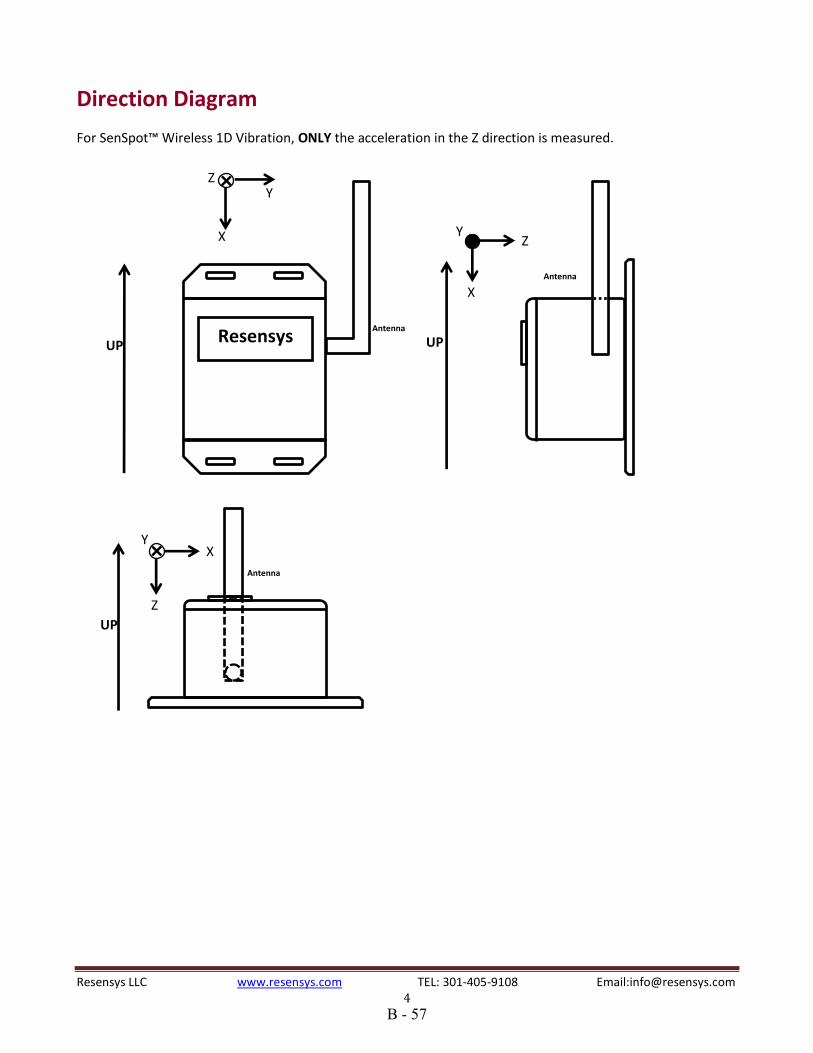
Resensys LLC www.resensys.com TEL: 301-405-9108 Email:[email protected] 4
Direction Diagram
For SenSpot™ Wireless 1D Vibration, ONLY the acceleration in the Z direction is measured.
Antenna Resensys
UP
X
Y Z
UP
Antenna
Z
X Y
UP
X
Z Y
Antenna
B - 57