TRANSLATION OF THE ORIGINAL INSTRUCTION MANUAL … · Electric chain hoist DGUV-54 (BGV-D8)...
32
11.17 Translation 9500.9003.1 TRANSLATION OF THE ORIGINAL INSTRUCTION MANUAL ELECTRIC CHAIN HOIST TYPE LP
Transcript of TRANSLATION OF THE ORIGINAL INSTRUCTION MANUAL … · Electric chain hoist DGUV-54 (BGV-D8)...

11.17 Translation 9500.9003.1
TRANSLATION OF THEORIGINAL INSTRUCTION MANUALELECTRIC CHAIN HOIST TYPE LP


3Swiss Lifting Solutions
Table of contentsSpare parts / Ordering spare parts ...................................................................................... 4
0 General instructions ..................................................................................................... 50.1 General safety instructions ................................................................................................................................................................... 50.1.1 Safety and hazard information .............................................................................................................................................................. 50.2 General safety regulations and organisational measures .................................................................................................................... 50.2.1 Warning markings / Legends / Warning signs ....................................................................................................................................... 50.3 Particular safety instructions ................................................................................................................................................................. 50.4 Instructions for hazard protection ......................................................................................................................................................... 60.4.1 Hazards - Mechanical ........................................................................................................................................................................... 60.4.2 Hazards - Electrical ............................................................................................................................................................................... 70.4.3 Sound pressure level ............................................................................................................................................................................ 70.5 Technical status .................................................................................................................................................................................... 70.5.1 Periodic checks ..................................................................................................................................................................................... 80.5.2 Warranty ................................................................................................................................................................................................ 80.6 Intended use ......................................................................................................................................................................................... 80.6.1 Use of the instruction manual ............................................................................................................................................................. 10
1 Description .................................................................................................................101.1 Operating conditions ........................................................................................................................................................................... 101.2 General description ............................................................................................................................................................................. 12
2 Start-up ......................................................................................................................132.1 Transport and assembling ................................................................................................................................................................... 132.2 Connecting .......................................................................................................................................................................................... 142.2.1 Electrical connection ........................................................................................................................................................................... 142.2.2 Braking system .................................................................................................................................................................................... 152.2.3 Load chain ........................................................................................................................................................................................... 162.2.4 Limit switch .......................................................................................................................................................................................... 172.2.5 Chain container ................................................................................................................................................................................... 17
3 Care and maintenance ................................................................................................183.1 General guidelines for maintenance and servicing ............................................................................................................................. 183.2 Care and maintenance ........................................................................................................................................................................ 193.2.1 Care overview ..................................................................................................................................................................................... 193.2.2 Maintenance overview ........................................................................................................................................................................ 193.2.3 Braking system .................................................................................................................................................................................... 193.2.4 Load chain ........................................................................................................................................................................................... 203.2.5 Chain guidance ................................................................................................................................................................................... 213.2.6 Limit stop ............................................................................................................................................................................................. 213.2.7 Gearing ............................................................................................................................................................................................... 213.2.8 Slipping clutch ..................................................................................................................................................................................... 213.2.9 Suspension parts ................................................................................................................................................................................ 21
4 Measures for achieving safe operating periods .......................................................... 224.1 Determining the actual operating time ................................................................................................................................................ 224.2 General overhaul ................................................................................................................................................................................. 234.3 Disposal .............................................................................................................................................................................................. 23
5 Appendix ....................................................................................................................245.1 Technical data ..................................................................................................................................................................................... 245.2 Electrical parameters .......................................................................................................................................................................... 265.3 EC Declaration of conformity .............................................................................................................................................................. 305.4 EC Declaration of incorporation .......................................................................................................................................................... 31

4 Swiss Lifting Solutions
Resellers / Agent
Original spare parts for the electric chain hoists can be acquired from the following addresses:
Manufacturer
GIS AG Tel. +41 (0)41 984 11 33Swiss Lifting Solutions Fax +41 (0)41 984 11 44Luzernerstrasse 50 [email protected] Schötz www.gis-ag.ch
The correct order numbers for original spare parts can be obtained from the relevant spare parts list. Please ensure that you have the following data on your chain hoist to hand. This will enable the correct spare parts to be supplied without delay.
Electric chain hoist type:
Serial number:
Year of manufacture:
Load capacity:
Spare parts / Ordering spare parts

5Swiss Lifting Solutions
Transport and assembly:• Electric chain hoists, single parts and large components should be carefully fixed to suitable and technically acceptable hoisting appara- tus / load lifting members.
Electrical connection:• Connection work is only to be performed by personnel specifically designated and trained for the job.
0.3 Particular safety instructions
Figure 0-1 Figure 0-2 Figure 0-3 Figure 0-4 Figure 0-5
0.2.1 Warning markings / Legends / Warning signs• Oil chain .................................................................figure 0-1• CE sign ..................................................................figure 0-2• Type plate ............................................................. figure 0-3• Data plate ............................................................. figure 0-4• Voltage .................................................................. figure 0-5
The instruction manual for the electric chain hoist must always be available within the operating area of the hoist. The instructions menti-oned in this manual must be strictly adhered to. Furthermore, supplementary to the instruction manual, the statutory regulations governing general accident prevention and environmental protection are to be enforced.Operating and service personnel must have read and understood the instruction manual, in particular the safety instructions, before com-mencing work. Protective equipment must be made available for operating and service personnel and worn at all times. The operator or his representative is responsible for supervising operating personnel and ensuring they are aware of the hazards and safety implications of working with the electric hoist.The manufacturer reserves the right to make technical changes to the product or changes to these instructions and assumes no liability for the completeness and up-to-dateness of these instructions. The original version of these instructions is in the German language. In case of doubt, the original German original version is exclusively valid as a reference document.
0.2 General safety regulations and organisational measures
0.1.1 Safety and hazard informationThe following symbols and terms are used in this instruction manual for safety and hazard instructions:
DANGER !Non-compliance, either in part or full, with operating instructions with this symbol can result in serious personal injury or fatal accidents. Warning information must be strictly adhered to.
CAUTION !Non-compliance, either in part or full, with operating instructions with this symbol can result in major damage to machinery, property or material. Information in the category "Caution" is to be exactly adhered to.
NOTEFollowing the instructions marked with this symbol will lead to more effective and straightforward operation. "Note" directions make work easier.
0.1 General safety instructions0 General instructions

6 Swiss Lifting Solutions
0.4.1 Hazards - Mechanical
Physical injury:Unconsciousness and injury through:• crushing, shearing, cutting and twisting• drawing in, ramming, piercing and rubbing• slipping, stumbling and falling
Causes:• crushing, shearing and twisting• parts rupturing or bursting
Safety options:• keep floor, equipment and machinery clean• eliminate leakages• observe the required safety distance
Hazardous areas must be clearly marked by warning signs and cordoned off. It must be ensured that warnings regarding hazardousareas are given due attention.
Hazards can stem from:• incorrect application• not following safety directions properly• not carrying out test and service work thoroughly
0.4 Instructions for hazard protection
Start-up / operation:• Before initial start-up, as well as daily start-up, carry out a visual check and carry out the predefined user-checks routine.• Only operate the electric chain hoist if the protective and safety equipment provided is ready and working.• Damage to the electric chain hoist and changes in its operational characteristics must be reported immediately to the responsible person.• After use, or when in a non-operational mode, the chain hoist should be secured against unauthorised and unintentional use.• Refrain from hazardous procedures.See also operational parameters (chapter 0.6).
Cleaning / service / repair / maintenance / refitting:• Use working platforms provided for assembly work at high level.• Do not use machine parts for this purpose.• Check electrical cables for damage or wear.• Ensure any oils or other agents used are collected and disposed of safely and in an environmentally sound manner.• Reassemble and check safety installations that have been disassembled for servicing or repairing the hoist once service and repair work has been completed.• Adhere to predefined testing and service intervals specified in the instruction manual.• Follow the directions in the instruction manual regarding exchanging parts.• Operating personnel should be informed before commencing special or refitting work.• Secure the repair working area.• Prevent the electric chain hoist from being unexpectedly switched on during service or repair work.• Erect warning signs.• Disconnect the power cable and ensure it cannot be switched on again by unauthorized personnel.• Retighten screw connections that have been loosened for repair or service work.• Replace non-reusable fixing elements and seals (e.g. self-locking nuts, washers, cotter pins, O-rings and seals).
Shut down / storage:• Clean and preserve (lubricate/grease) the chain hoist before long periods of inactivity or storage.

7Swiss Lifting Solutions
This instruction manual was issued in 2016. It corresponds to directive 2006/42/EC of the European Parliament and council of 17 May 2006. The LP models are calculated for the case of operation with a shock factor of 1.4 (according to DIN EN 818-7 with max. 8 m/min.). The accidents audited by the laboratory generate smaller shock factors than the normal mode.
0.5 Technical status
When working in a noisy environment, the use of ear protection is recommended.
Measuring distance 1 m 2 m 4 m 8 m 16 m
Types Measurement type dBA
LP 500 ab
6060
5754
5448
5142
4836
LP 500 1Ph ab
7676
7370
7064
6758
6452
LP 1000 ab
7575
7269
6963
6657
6351
Table 0-1 Sound level
0.4.3 Sound pressure levelTests on the chain hoist sound level are performed at a range of 1, 2, 4, 8 and 16 metres from the centre of the chain hoist motor to the measuring device. Measurement of SPL according to DIN 45 635.
The SPL was measured:a) During operation of electric chain hoists on factory site.b) During open-air operation of electric chain hoists.
Physical injury:Death from electrical shock, injury and burns through:• contact• faulty insulation• faulty servicing or repair work• short circuit
Causes:• contact with, touching or standing too close to uninsulated power and live parts• use of uninsulated tools• exposed electricity supply terminals following insulation failure• inadequate safety checks following repair work• incorrect fusing
Safety options:• Isolate machinery and equipment designated for repair or service work before commencing such work.• First check isolated parts for voltage.• Regularly check electrical fittings.• Replace loose or damaged cables immediately.• Always replace blown fuses with fuses of the correct type/value.• Avoid contact with or touching live terminals.• Only use insulated tools.
0.4.2 Hazards - ElectricalWork on electrical apparatus or machinery may only be performed by qualified electricians or persons under the supervision and guidance of qualified electricians, in accordance with predefined electro-technical regulations.

8 Swiss Lifting Solutions
General operating conditions:• Ambient temperature ............................. : -15 °C to +50 °C• Humidity ................................................. : max. 80% relative humidity• Protection class ..................................... : IP 65• Electromagnetic compatibility ................ : immunity industrial area
We recommend to equip GIS chain hoists working outdoors with a shelter against the weather. Special operating conditions can be agreed in individual cases with the manufacturer. After consultation, appropriate, optimized equipment, and important information for safe, low-wear use can be supplied. The intended use of the electric chain hoist likewise assumes the adherence to the operating, maintenance and servicing prescribed by the manufacturer.
Ensure that only one type of hoist from the same manufacturer with the same speed is used to lift each assembly. Different hoists or hoists with different lifting capacity/speeds should not be used to lift one rig. Note that different manufactured hoists and hoists with different lifting capacities even when noted with the same hoisting speed will run at different speeds.
The electric chain hoists in the LP series are designed for provision and use at events. Events include concerts, shows, events, conven-tions, conferences, exhibitions, presentations, demonstrations, cinema or television recordings and the like. Venues include theatres, multi-purpose halls, studios, production facilities for film, television and radio, concert halls, convention centres, schools, exhibitions, trade fairs, museums, discos, variety shows, theme parks, sports facilities, open air theatres and open-air events.
There are three types of electric chain hoists:
D8 HoistElectric chain hoist DGUV-54 (BGV-D8) "Winches, lifting and pulling devices" as construction chain hoists for lifting loads.
The electric chain hoists of the LP types are lifting equipment for various loads. They can be installed as stationary or mobile units, while a lateral oscillation must be ensured. The electric chain hoists are manufactured in accordance with the latest technical developments and recognised safety standards, and are tested for safe operation by the manufacturer. Electric chain hoists are approved by various interna-tional classification societies such as TÜV and others. Electric chain hoists of the above types may only be used when in an acceptable technical condition, in accordance with their intended use, by trained personnel in a safe and responsible manner.
0.6 Intended use
0.5.2 WarrantyThe warranty is void if the installation, operation, testing and maintenance is not carried out according to this manual. Repairs and trouble-shooting under warranty may only be carried out by qualified persons after consultation and agreement with the manufacturer / supplier. Any modifications to the product or the use of non-original spare parts will void the warranty.
0.5.1 Periodic checksEach device/unit operator should adequately note all checks, maintenance and inspections performed in the log book, and have these confirmed by the competent person in charge. Incorrect or missing entries will lead to forfeiture of the manufacturer's warranty.
Equipment and cranes are to be checked periodically by a specialist. Primarily, visual and functional checks are to be car-ried out, whereby the state of components with respect to damage, wear, corrosion or any other changes are determined. In addition, safety equipment is assessed for completeness and efficiency. It may be necessary to dismantle the equipment to correctly assess wear parts.
Suspensions must be inspected over its entire length, including covered or hidden parts.
All periodical inspections should be arranged by the operator.

9Swiss Lifting Solutions
Excessive inching operations, ground mooring and driving against the limit stops should be avoided. The loads shall be lifted off the ground at the lowest available lifting speed (according to EN 14492). If these instructions are not followed, the manufac-turer accepts no liability for damage to equipment and third parties caused by such actions.
Figure 0-6
For hoists permanently installed in venues facilities, due to the operation and the expected hazard, electric chain hoists according to DGUV 17 (BGV-C1) are to be deployed.
Improper use comprises:• exceeding the defined maximum permissible load capacity• pulling the load diagonally (maximum angle 4°, see figure 0-6)• heaving, pulling or dragging the load• transporting persons• transporting excessive loads• puling on the control cable• failing to observe the load hook constantly• running the chain over edges• failing to observe the load constantly• allowing the load to fall due to a slack chain• use in an explosive environment
See also chapter 0.3.
In the presence of persons under the load
Use D8 D8 with secondary safety device D8 PLUS C1
Assembly and dismantling, set up mode inadmissible inadmissible inadmissible permissible
Holding loads inadmissible permissible permissible permissible
Scenic movement inadmissible inadmissible inadmissible permissible
Table 0-2 Operating conditions
Electric chain hoists are offered in a variety of types and equipment variants and with different safety devices. Therefore, the choice of chain hoists are of considerable importance. Here, the resulting hazards from the type of use hazards are to be based in compliance with the specific conditions of use. The selection of the type of the electric chain hoist is dependent on the operating conditions.
D8 PLUS HoistElectric chain hoist DGUV-54 (BGV-D8) "Winches, lifting and pulling devices" as construction chain hoist for lifting loads with the particu-lar feature to hold loads over persons in the idle state without secondary safety.
C1 Hoist (scenery hoist)Electric chain hoist DGUV-17 (BGV-C1) "Venues and production sites for stage performances" for holding and moving loads above per-sons.
The types of electric chain hoists listed above can be operated both individually and in groups.

10 Swiss Lifting Solutions
The manufacturer will only guarantee the safety and lasting operation of the electric chain hoist when used for applications in accordance with valid standard values that fall within its classification.Before the first start-up, the user must estimate according to the parameters in table 1-1, which of the four types of load is applicable to the use of the electric chain hoist during its whole life cycle. The table 1-2 shows standard values for the operating conditions of the classifica-tions depending on the type of load and time of operation.
Classification according to application requirements:Electric chain hoists and trolleys are categorised according to the following regulations into classifications:• DIN EN 14492-2• DIN 15401 (load hook)• FEM calculation regulations for series lifting equipment (chain drive, motor, full load-life cycle)• Remarks about general overhaul (see chapter 4)
There is different coefficient data for the classifications that must be adhered to in operation.
The travel trolley must have at least the same lifting capacity as the electric chain hoist.
The classification of the electric chain hoist can be found on the data plate.
1.1 Operating conditions
The LP series includes the following models: D8, D8 PLUS, C1.
1 Description
0.6.1 Use of the instruction manualThis instruction manual includes the following chapters:0 General instructions 3 Care and maintenance1 Description 4 Measures for achieving safe operating periods2 Start-up 5 Appendix
Supplementary to the instruction manual, the following documentation from the operator must be noted:• Declaration of conformity• Inspection pass• Spare parts list(s)• Circuit diagrams
Page- and figure numbering:The pages are consecutively numbered. Blank pages are not numbered, however are calculated together with the consecutive pages. Figures are numbered consecutively by chapter. Example: Figure 3-1 means: in chapter 3, figure 1.

1090
100
80
50 50
100
33
16.7 50
100
0~
40
16.716.7
70
10 40 50
100
0~
40
11Swiss Lifting Solutions
Example 1: Calculate permissible operating time of the electric chain hoistAn electric chain hoist of the classification M4 is to be used for medium stress load tasks throughout its whole calculated operating time. This corresponds to the type of load <3 heavy> (see table 1-1). Corresponding to the values in table 1-2, the hoist should not be used for more than 0.5 - 1 hour per day.
Example 2: Calculate the permissible type of loadAn electric chain hoist of the classification M5 is to be used for approximately 6 hours per working day, throughout its whole calculated operating time. Thus, the electric chain hoist must be operated according to the characteristics of the type of load <1 light> (see table 1-1).
Ascertaining the correct type of application for an electric chain hoist:Either the operating time or expected type of load can be used as a basis for ascertaining the correct type of application for the electric chain hoist.
Before initial operation of the electric chain hoist, it must be set, according to which load types contained in table 1-1 the electric chain hoist must be operated. Assignment to a load type or a load collective (k) applies for the whole service life of the equipment and may not be altered for operational safety reasons.
Classificationaccording to ISO 4301-1 M3 M4 M5 M6 M7
Load collective Average operating time per working day [h]
1 - light k < 0.50 up to 2 2 - 4 4 - 8 8 - 16 over 16
2 - medium 0.50 < k < 0.63 up to 1 1 - 2 2 - 4 4 - 8 8 - 16
3 - heavy 0.63 < k < 0.80 up to 0.5 0.5 - 1 1 - 2 2 - 4 4 - 8
4 - very heavy 0.80 < k < 1.00 up to 0.25 up to 0.5 0.5 - 1 1 - 2 2 - 4
Table 1-2 Operating conditions
k = Load collective (type of load)
Load type 1light
k < 0.50k = 0.50
Load type 2medium
0.50 < k < 0.63k = 0.63
Load type 3heavy
0.63 < k < 0.80k = 0.80
Load type 4very heavy
0.80 < k < 1.00k = 1.00
% o
f lift
ing
capa
city
% o
f lift
ing
capa
city
% o
f lift
ing
capa
city
% o
f lift
ing
capa
city
% of operating time % of operating time % of operating time % of operating time
Full load by way of an exception, however
predominantly low loads
Frequently fully loaded, however continuously
lightly loaded
Frequently fully loaded, continuous average
loading
Regularly fully loaded
Table 1-1 Load collectives
12 Swiss Lifting Solutions
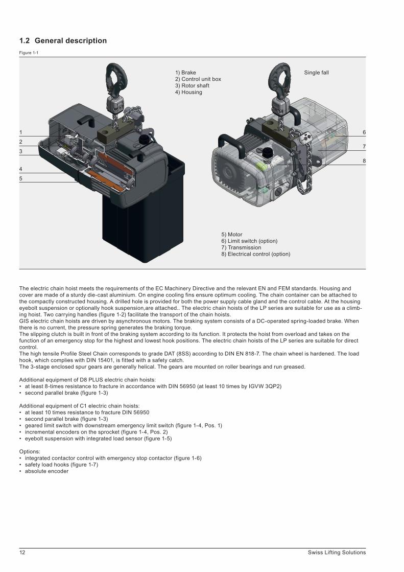
The electric chain hoist meets the requirements of the EC Machinery Directive and the relevant EN and FEM standards. Housing and cover are made of a sturdy die-cast aluminium. On engine cooling fins ensure optimum cooling. The chain container can be attached to the compactly constructed housing. A drilled hole is provided for both the power supply cable gland and the control cable. At the housing eyebolt suspension or optionally hook suspension,are attached.. The electric chain hoists of the LP series are suitable for use as a climb-ing hoist. Two carrying handles (figure 1-2) facilitate the transport of the chain hoists.GIS electric chain hoists are driven by asynchronous motors. The braking system consists of a DC-operated spring-loaded brake. When there is no current, the pressure spring generates the braking torque.The slipping clutch is built in front of the braking system according to its function. It protects the hoist from overload and takes on the function of an emergency stop for the highest and lowest hook positions. The electric chain hoists of the LP series are suitable for direct control.The high tensile Profile Steel Chain corresponds to grade DAT (8SS) according to DIN EN 818-7. The chain wheel is hardened. The load hook, which complies with DIN 15401, is fitted with a safety catch.The 3-stage enclosed spur gears are generally helical. The gears are mounted on roller bearings and run greased.
Additional equipment of D8 PLUS electric chain hoists:• at least 8-times resistance to fracture in accordance with DIN 56950 (at least 10 times by IGVW 3QP2)• second parallel brake (figure 1-3)
Additional equipment of C1 electric chain hoists:• at least 10 times resistance to fracture DIN 56950• second parallel brake (figure 1-3)• geared limit switch with downstream emergency limit switch (figure 1-4, Pos. 1)• incremental encoders on the sprocket (figure 1-4, Pos. 2)• eyebolt suspension with integrated load sensor (figure 1-5)
Options:• integrated contactor control with emergency stop contactor (figure 1-6)• safety load hooks (figure 1-7)• absolute encoder
5) Motor6) Limit switch (option)7) Transmission8) Electrical control (option)
6
7
8
1
2
3
4
5
Single fall1) Brake2) Control unit box3) Rotor shaft4) Housing
Figure 1-1
1.2 General description

1
2
13Swiss Lifting Solutions
The safety directions for handling with loads should be followed (see chapter 0.3) when transporting and assembling the electric chain hoist. Electric chain hoists must be assembled by qualified staff, always bearing in mind the accident prevention directions in chapter 0.2. Before start-up, the electric chain hoist must be stored in an closed room or covered area. Should the electric chain hoist be destined for operation outdoors, then it is recommended that a protective cover is erected to shield it from the effects of the weather.
2.1 Transport and assembling
Mechanical adjustments may only be performed by authorised specialists.
Operating staff must carefully read the instruction manual of the electric chain hoist before initial operation and carry out all the checks. Only after safe operation has been established, the device is put into operation. Unauthorised persons may not operate the device or carry out work with it.
The operator must create an inspection pass when starting-up the electric chain hoist. The inspection pass contains all the technical data and the date of start-up. It provides a record of all servicing and maintenance work.
2 Start-up
Figure 1-5 Figure 1-6 Figure 1-7
Figure 1-2 Figure 1-3 Figure 1-4

NA
1 sp
eed
4
2
3
1
441
spee
d3 3
3
4
2 sp
eed
2 sp
eed
2
red
21
red
1
2 1 10 4 3
43
12
10
123410
L3
L2
L1
PE
PE
L1 U
L2 V
L3 W
14 Swiss Lifting Solutions
Figure 2-1 Figure 2-2 Figure 2-3
• Before connecting the electric chain hoist, check whether the operating voltage and frequency that are specified on the type plate correspond to the available power supply.• Remove the cover from the control unit box.
Connection with direct control:• Introduce the connection cable with cable gland M25 × 1.5 in the lower hole and according connect according to the attached electrical chart to L1, L2, L3 and PE (see figure 2-1).• With direct operated chain hoists without PMS relay contact is provided for connection of the brake. The brake must be switched on the direct current side.
Connection with contactor control:• Align connection cable with cable gland M25 × 1.5 in lower hole and connect according to the attached electrical chart to L1, L2, L3 and PE (see figure 2-2).• Align control cable through cable gland M20 × 1.5 into the hole below the casing and connected to terminals 1, 2, 3, 4, 10 (see figure 2-3).
2.2.1 Electrical connectionElectrotechnical installations may only be performed by authorised specialists.
The mains connection cable, the mains connection fuse and the main control switch for connecting the electric chain hoist to the mains power supply must be provided by the customer. A 4-wire cable with a PE protective conductor is needed to provide the power supply for three-phase versions. A 3-wire cable with a protective conductor is adequate for single-phase version. The length and cross-section must be appropriate for the power consumption of the electric chain hoist. The wiring diagram is located in the lid of the electric chain hoist. In D8 PLUS electric chain hoists, the power supply must be interrupted by means of a lockable switch, after reaching the desired position.The control system must be fitted with an emergency stop button which are monitored. Power should be disconnected from control units when hoists are not in use. Only experienced and competent users may operate lifting systems or single hoists.The principles according to BGG 912/GUV-G 912 are to be applied. A test log is to be created consisting of the installation documentation from the manufacturer and the test records. Plans and descriptions for electrical installation are specific projects complemented by the appropriate control engineer.
2.2 Connecting
The electric chain hoist must have the following identification:• Electric chain hoist D8 ........................... : triangle• Electric chain hoist D8 PLUS ................. : square• Electric chain hoist C1 ........................... : circle
Wherever possible, the electric chain hoist should be transported in its original packaging. The goods delivered should be checked for completeness and the packaging has to be disposed in an environmentally sound manner. It is recommended that the electric chain hoist is assembled and connected on-site by our qualified customer service engineers. On the type plate it must be checked whether the hoist corresponds to the version ordered (D8 / D8 PLUS / C1).

8-9
mm
15Swiss Lifting Solutions
2.2.2 Braking systemThe brake must be able to hold the nominal load in power free mode without any problems. For chain hoists with two brakes, the function-ality of the brakes must be checked during the acceptance of the system. The first brake on the DC side, the second brake switched on the AC side and thereby switches slightly delayed.The functional tests on two braking systems are carried out under nominal load:
1. Brake:Release the mounting screws of the 2nd brake. The rotor of this brake now rotates freely. The function of the second brake is disconnect-ed. Raise and lower: The first brake must be capable of braking and hold the nominal load. Tighten the mounting screws again after the function test.
2. Brake:Electrical Method:The first brake is released from + and - terminals and activated by a non-controlled current source (directly from L1 and L2). To activate a rectifier must be switched between. Thus, the first brake is disconnected and the second brake can be tested by lifting and lowering the load. Lifting and lowering with unloaded first Brake: The second brake must be capable of braking and hold the nominal load. After the function test reconnect the first brake to the terminals + and -.
Mechanical method:With a tool, the pressure ring of the first brake is pressed to the solenoid, so that the rotor of the brake can rotate freely. The function of the first brake is disconnected. Lifting and lowering with unloaded first brake: The second brake must be capable of braking and hold the nominal load.
Figure 2-4 Figure 2-5
The protective conductor should not conduct any current. With the installation of a motor protector, the current of the electric chain hoist must be observed according to the type plate.
• Checking direction of rotation: If the directions of movement do not match the button symbols of the control switch, the supply line wires L1 and L2 must be changed.• In the single-phase version, inching operations can cause malfunctions.
Open the terminal that is used in accordance with figure 2-5.
When using a control switch:• strain relief to housing (see figure 2-4)
• To maintain the predetermined protection class IP 65, all cables must fit into the corresponding cable glands and the cover screws must be tightened after the connection with the torque specified in table 3.2.9.• The control switch must be attached to the strain relief cord and not to the cable.

k1
3
1
2
1
1
3
2
16 Swiss Lifting Solutions
Figure 2-7 Figure 2-8 Figure 2-9
Chain end:The chain end is to be fixed to the housing according to figure 2-7. The section of chain after the limit stop (1) must be adjusted to the height of the chain container. Here, the length of the chain section must be selected that the limit stop lies on the floor of the container when the chain is pulled into it.
1 fall operation:The load hook (1) is connected to the chain with a single fall hook clamp (2). For the power transmission, the mounting of the bolt (3) is important (see figure 2-8).
• Note correct arrangement of suspension (mass k1, see figure 2-9): LP 500 = 41 mm, LP 1000 = 43 mm.• Grease the bearings thoroughly (load hook).
Figure 2-6
2.2.3 Load chain• Only use original chains.• Welded seam of the chain links must face inward on the chain wheel (see figure 2-6).• When used as a climbing hoist, make sure that the entry and the outlet of the chain is not prevented by chain clusters.• The geared limit switch must be mechanically set for pulling in the chain, see chapter 2.2.4.
Before start-up and during operation, the load chain must be oiled along its full length. Oil must constantly be present on the internal, contacting and rubbing surfaces of the chain links. Lubrication is carried out by submersion or with an oil can, using a creeping gear oil. The end of the chain (1) should be attached to a flexible piece of wire or chain pulling loop (2) and fed through the chain wheel (3) of the electric chain hoist. Through short switching impulses, the chain will be pulled in correctly according to figure 2-6. The lifting height must be adjusted such that the hook fittings lie on the ground in the lowest hook position.

17Swiss Lifting Solutions
2.2.5 Chain container• Textile chain container are suitable for vertically mounted electric chain hoists and for climbing hoists.• Attach the free end of chain to housing (see chapter 2.2.3).• Attach the chain container and allow chain to run in: Vertically mounted chain hoist (see figure 2-11) or climbing hoist (see figure 2-12).
Chain container must hang freely. Badly lubricated chain will occupy more volume in a chain container. We recommend a maxi-mum of 50% to 70% fullness.
Description of settings (see figure 2-10):• Before pulling in the chain or changing the chain, the geared limit switch must be set mechanically inactive by pressing the rocker (1).• Pulling the chain in.• Travel to the hook's highest position, turn the red control wheel (2, rear) to the cam of the limit switch above (3) turn (lower hook position clockwise, higher hook position anti-clockwise).• Enable rocker switch (1) (must engage in control wheel).• Bring the hook to its lowest position, press the rocker switch (1) and turn the green control wheel (4, front) to the cam of the limit switch below (5) (lower hook position clockwise, higher hook position anti-clockwise).• Enable rocker switch (1) (must engage in control wheel).
Check the limit switching function: The limit stop and the hook fittings may not contact the housing. Check downstream emer-gency limit switch.
LP 1000
Transmission Colour 1 fall lift [m]
i = 1:1 black 30
i = 1:3 yellow 90
i = 1:6 blue 192
LP 500
Transmission Colour 1 fall lift [m]
i = 1:1 black 20
i = 1:3 yellow 60
i = 1:6 blue 126
2.2.4 Limit switchIn direct-operated electric chain hoists no termination circuit is installed. It is important to ensure that is not operationally driven against the housing. The gearing of the protective controlled electric chain hoist is only allowed for control voltage up to 230 V AC.
In electric chain hoists with contactor control, a gear is built in as standard. This is also suitable for normal limit switch operation with a high degree of accuracy. The operation of the limit switches (highest and lowest hook position) must be checked during start-up. Three different transmission gearings are available that are adapted to the lift:

31
2
5
4
18 Swiss Lifting Solutions
General:Service and maintenance are preventive measures designed to preserve the full functionality of electric chain hoists. Non-compliance with service and maintenance routines can result in limited use and damage to electric chain hoists.Service and maintenance should be carried out according to the instruction manual at predefined time intervals (table 3-1 and 3-2). During service and maintenance work, general accident prevention directions, special safety directions (chapter 0.3) as well as hazard protection instructions (chapter 0.4) should be followed.
Service and maintenance work should only be performed at unloaded electric chain hoists. The main switch must be off. The hook fittings must lie on the ground or on the maintenance platform.
Service work encompasses visual checks and cleaning routines. Maintenance work includes additional functional checks. During the functional checks, all fixing elements and cable clamps must be checked for tightness. Cables must be inspected for dirt, discolouration and arc spots.
Used operating materials (oil, grease, etc.) should be safely collected and disposed of in an environmentally friendly manner.
Operating failures in electric chain hoists affecting the safe operation of the device should be remedied immediately.
Maintenance and repair work on the electric chain hoist may only be carried out by qualified and trained personnel.
If the operator performs maintenance work on an electric chain hoist on his own , the type of maintenance performed together with the date carried out must be entered in the inspection pass.
Alternations to, as well as modifications and supplements to electric chain hoists, which may affect safety, must be authorised by the manufacturer in advance Structural alterations to chain hoists not authorised by the manufacturer exempt the manufacturer from liability in case of damage. Material warranty claims will only be recognised as valid if exclusively original manufacturer's spare parts are used. We explicitly advise that original parts and accessories not delivered by us are also not checked and released by us.
3.1 General guidelines for maintenance and servicing3 Care and maintenance
Figure 2-10 Figure 2-11 Figure 2-12

19Swiss Lifting Solutions
3.2.3 Braking systemThe spring-loaded brake is an solenoid operated single disk brake with two friction surfaces. The braking force is applied by springs. The braking torque is generated when no current is applied. The ventilation is solenoid. The brake operates with DC current.The brake must be able to hold the nominal load in power free mode without any problems. For chain hoists with two brakes, the func-tionality of the two brakes must be checked on the system acceptance test and tested periodically. The periodic examination takes place annually by a competent person and every 4 years by an expert.The function test is described in Section 2.2.2. The verifiability of individual brakes is ensured by the control engineer. A pattern control scheme for a D8 PLUS electric chain hoist can be obtained from GIS.
The brake coil voltage must be the same as the operating voltage.
If the maximum air gap is reached (a max., table 3-3 and figure 3-1) is reached, the lining and the brake disk must be replaced.
Term d 3 M 12 M Activity Notes
Load chain xx
lubricatemeasure wear
see chapter2.2.3 / 3.2.4
2. Braking system x x function check with load see chapter 3.2.3
3. Electrical equipment x function check
4. Fixing screws on suspension parts and load hook with accessories
x check for crackscheck screw torque
see chapter 3.2.9
5. Limit switch x check switching elements see chapter 2.2.4
6. Slipping clutch x function check see chapter 3.2.8
7. Tightness x check screw torques of the coverscheck cable glands
see chapter 3.2.9
3.2.2 Maintenance overviewTable 3-2 Maintenance overview
Term d 3 M 12 M Activity Notes
1. Load chain x visual checkclean and lubricate as needed
see chapter 2.2.3
2. Lifting device and trolley x check for abnormalnoise / sealing
3. Electric power supply cable x visual check
4. Limit switch x function check see chapter 2.2.4
5. Sealing x visual check
6. Strain relief control cable x visual check
3.2.1 Care overviewTable 3-1 Care overview
3.2 Care and maintenance
Service and maintenance intervals are defined as follows:d (daily), 3 M (quarterly), 12 M (annually)
The predefined service and maintenance intervals should be reduced when the loading of the electric chain hoist is exceptionally large and when frequently operated in adverse conditions (e.g. dust, heat, humidity, steam, etc.).

t
b
a=11t
d
d1
d2
a
20 Swiss Lifting Solutions
Figure 3-1 Figure 3-2
Term LP 500 LP 1000
Chain type d x t [mm] 5.25 x 15 7.45 x 23
Tolerances according toDIN 685, part 5 DIN EN 818-71. Measurement over 11 chain links, a = 11t [mm] 168.3 258.1
2. Measurement over 1 chain link 1t [mm] 15.7 24.1
3. Measurement of the chain link diameter dm = d1 + d2 / 2 (dm min. = 0.9 x d) [mm] 4.7 6.7
Tabelle 3-4 Verschleisswerte Lastkette
3.2.4 Load chainThe load chain should be periodically checked for abrasion. The check is based on three measurements: see permissible wear and tear values (table 3-4) and measuring points (figure 3-2).
The chain should be replaced when the measurements exceed or decrease with those defined in the table. The chain wheel and chain guidance should be checked for wear at the same time and, where necessary, be replaced. Only use original chains. The chain links should not be welded.
The new chain is installed in accordance with chapter 2.2.3.
For ease of installation, the old chain and new chain can be connected by a piece of flexible wire.
Term LP 500 LP 1000
Par value air gap (a) [mm] 0.3 (+0.1 / -0.05) 0.3 (+0.15 / -0.05)
Air gap (a max.) [mm] 0.7 0.9
Torque value [Nm] 3 6
Table 3-3 Air gap

21Swiss Lifting Solutions
Suspension part LP 500 LP 1000
Load hookh [mm] 28.0 35.5
h min. [mm] 26.6 33.8
Hook suspensionh [mm] 28.0 35.5
h min. [mm] 26.6 33.8
Eyebolt suspensionh [mm] 15.0 20.0
h min. [mm] 14.3 19.0
Hook openingl [mm] 34.5 42.6
l max. [mm] 37.9 46.8
Table 3-5 Wear values suspension parts
If hook or eyebolt show damage, cracks, deformation or corrosion, they must be replaced. If the prescribed dimensions (min. / max.) according to table 3-5 and figure 3-3 are not compliant, the parts must also be replaced. The hook safety catch must be fully functional and fully closed, replace if necessary.
M 4 M 5 M 6 M 8 M 10 M 12
3.3 Nm 6.5 Nm 10 Nm 24 Nm 48 Nm 83 Nm
3.2.9 Suspension partsAll statically loaded parts are considered to be suspension parts. The bearing surfaces of the slewing suspension parts must be periodi-cally greased. Torque values for screws of property class 8.8 according to DIN ISO 898:
3.2.8 Slipping clutchThe slipping clutch is set at the works to 125% and reliably prevents overloading of the chain hoist (the power limiting factor in accordance with DIN EN 14492-2 is ΦDAL = 1.4). The resultant forces arising from the adjustment of the slipping clutch must be able to be absorbed by the suspension parts. The coating is wear resistant.
Adjustment and testing of the slipping clutch may only be carried out by authorised personnel and must be recorded in the inspection pass. If the nominal load is no longer lifted, or there is delay in achieving the lifting speed, the slipping clutch must be adjusted.
3.2.7 GearingThe gear has continuous lubrication.
The housing of the gearbox may not be opened.
3.2.6 Limit stopCheck screw fittings at the limit stop and single fall hook clamp and tighten with the correct torque if necessary. For coefficient data see chapter 3.2.9.
3.2.5 Chain guidanceThe inlet openings of the chain are visually inspected.
A damaged wear plate, underneath the housing, must be replaced.

h
h
l
22 Swiss Lifting Solutions
Example:An electric chain hoist with M4 classification is used with the load type <3 heavy> (k = 0.80, see table 1-1). The daily operating time per working day is 0.5 - 1 hour. According to table 4-1, this results in an annual operating time of 96 full load hours. With a theoretical opera-ting time of 800 hours a period of 8.3 years is thus created. After this period of time a general overhaul must be carried out, during which the further operating time is determined.
The actual operating time depends on the daily operating hours and the load collective. Operating hours is determined from information provided by the operator or recorded using a meter that counts the number of operating hours. The load collective is determined in accord-ance with table 1-1, page 11. With these both values, the annual operating time can be found in table 4-1. If an operating data acquisition system (BDE) is used, the actual operating time can be read out directly by our experts during the annual inspection.
The values periodically calculated or read-off are to be recorded in the inspection pass.
4.1 Determining the actual operating time
M3 M4 M5 M6 M7 M8
400 h 800 h 1600 h 3200 h 6300 h 12500 h
The following theoretical operating time applies to electric chain hoists that are categorised according to ISO 4301-1 (converted into full-load hours):
The statutory and health requirements of the EU regulations stipulate that specific dangers which may arise from fatigue or ageing must be prevented. Accordingly, operators of series lifting device are obliged to determine the actual operating time. This determination is easiest using the calculator on our website. The actual operating time is recorded as part of the annual inspection by customer service engineers. A general overhaul must be carried out when the theoretical operating time is reached, or after no more than 10 years. All checking and the general overhaul itself must be arranged by the operator of the lifting device.
4 Measures for achieving safe operating periods
Figure 3-3

23Swiss Lifting Solutions
If no use of the device is possible anymore, it must be disposed environmentally safe. Lubricants, such as oils and greases, must be dispo-sed in accordance to the applicable waste law. Metals and plastics are to be recycled.
4.3 Disposal
* replace if worn ** replace at the latest in general overhaul
Components of LP models, all types Check for wear * Replace
Brake x
Motor shaft x
Gear teeth x
Antifriction bearing x
Sealings x
Chain x **
Chain wheel, chain guidance x
Suspension x
Load hook x
Trolley, load wheel x
Contactor, limit switch x
Table 4-2 General overhaul
On reaching the theoretical operating time (no later than 10 years for recording without BDE), a general overhaul should be performed. This enables the equipment to continue operating safely for a further period of time. Components must be checked or replaced in accord-ance with table 4-2. The checking and release for the further use must be done by a specialist company authorised by the manufacturer or by the manufacturer himself.
The inspector determines:• What new theoretical operating time is possible.• The max. period until the next general overhaul.
This data should be recorded in the inspection pass.
4.2 General overhaul
Useper day [h]
<= 0.25(0.16)
<= 0.50(0.32)
<= 1.0(0.64)
<= 2.0(1.28)
<= 4.0(2.56)
<= 8.0(5.12)
<= 16.0(10.24)
> 16.0(20.48)
Load collective Annual operating time in full load hours [h]
k = 0.50 6 12 24 48 96 192 384 768
k = 0.63 12 24 48 96 192 384 768 1536
k = 0.80 24 48 96 192 384 768 1536 3072
k = 1.00 48 96 192 384 768 1536 3072 6144
Table 4-1 Annual operating time

ISO
(FE
M)
clas
sific
atio
nM
5 (2
m)
240
s/h,
40
% d
uty
M5
(2m
) 24
0 s/
h, 4
0 %
dut
yM
5 (2
m)
240
s/h,
40
% d
uty
Lifti
ng
spee
d 50
Hz
Lifti
ng
spee
d 60
Hz
Mot
or ty
peN
o. o
f ch
ain
falls
Mai
ns fu
se
(del
ayed
)
Type
sD
ead
wei
ght
Cap
acity
no
rmal
ho
ist
Cap
acity
cl
imbi
ng
hois
t
Tota
l cap
a-
city
clim
- bi
ng h
oist
Cha
in s
ecu-
rit
y no
rmal
/ cl
imbi
ng
hois
t
Cap
acity
no
rmal
ho
ist
Cap
acity
cl
imbi
ng
hois
t
Tota
l cap
a-
city
clim
- bi
ng h
oist
Cha
in s
ecu-
rit
y no
rmal
/ cl
imbi
ng
hois
t
Cap
acity
no
rmal
ho
ist
Cap
acity
cl
imbi
ng
hois
t
Tota
l cap
a-
city
clim
- bi
ng h
oist
Cha
in s
ecu-
rit
y no
rmal
/ cl
imbi
ng
hois
t
[kg]
[kg]
[kg]
[kg]
[kg]
[kg]
[kg]
[kg]
[kg]
[kg]
[m/m
in]
[m/m
in]
[A]
LP 5
00/1
NL
C1
LP 5
00/1
N C
1 LP
500
/1N
F C
1
24
24
24
400
400
400
376
376
376
400
400
400
10.0
10
.0
10.0
320
320
320
296
296
296
320
320
320
12.5
12
.5
12.5
250
250
250
226
226
226
250
250
250
16.0
16
.0
16.0
4 8 8/2
4.8
9.6
9.6/
2.4
80 A
4
80 B
2
80 A
8/2
1 1 1
6 6 6
Tabl
e 5-
3 Te
chni
cal d
ata
LP C
1
ISO
(FE
M)
clas
sific
atio
nM
5 (2
m)
240
s/h,
40
% d
uty
M3
(1B
m)
150
s/h,
25
% d
uty
M5
(2m
) 24
0 s/
h, 4
0 %
dut
yLi
fting
sp
eed
50 H
z
Lifti
ng
spee
d 60
Hz
Mot
or ty
peN
o. o
f ch
ain
falls
Mai
ns fu
se
(del
ayed
)
Type
sD
ead
wei
ght
Cap
acity
no
rmal
ho
ist
Cap
acity
cl
imbi
ng
hois
t
Tota
l cap
a-
city
clim
- bi
ng h
oist
Cha
in s
ecu-
rit
y no
rmal
/ cl
imbi
ng
hois
t
Cap
acity
no
rmal
ho
ist
Cap
acity
cl
imbi
ng
hois
t
Tota
l cap
a-
city
clim
- bi
ng h
oist
Cha
in s
ecu-
rit
y no
rmal
/ cl
imbi
ng
hois
t
Cap
acity
no
rmal
ho
ist
Cap
acity
cl
imbi
ng
hois
t
Tota
l cap
a-
city
clim
- bi
ng h
oist
Cha
in s
ecu-
rit
y no
rmal
/ cl
imbi
ng
hois
t
[kg]
[kg]
[kg]
[kg]
[kg]
[kg]
[kg]
[kg]
[kg]
[kg]
[m/m
in]
[m/m
in]
[A]
LP 5
00/1
NL
D8
PLU
S
LP 5
00/1
N D
8 P
LUS
LP
500
/1N
F D
8 P
LUS
LP
500
/1N
L 1P
h D
8 P
LUS
23
23
23
23
500
500
500
500
477
477
477
477
500
500
500
500
8.0
8.0
8.0
8.0
400
400
400
400
377
377
377
377
400
400
400
400
10.0
10
.0
10.0
10
.0
320
320
320
320
297
297
297
297
320
320
320
320
12.5
12
.5
12.5
12
.5
4 8 8/2 4
4.8
9.6
9.6/
2.4
4.8
80 A
4
80 B
2
80 A
8/2
80
A 4
1 1 1 1
6 6 6 10
Tabl
e 5-
2 Te
chni
cal d
ata
LP D
8 P
LUS
ISO
(FE
M)
clas
sific
atio
nM
3 (1
Bm
) 15
0 s/
h, 2
5 %
dut
yM
4 (1
Am
) 18
0 s/
h, 3
0 %
dut
yM
5 (2
m)
240
s/h,
40
% d
uty
Lifti
ng
spee
d 50
Hz
Lifti
ng
spee
d 60
Hz
Mot
or ty
peN
o. o
f ch
ain
falls
Mai
ns fu
se
(del
ayed
)
Type
sD
ead
wei
ght
Cap
acity
no
rmal
ho
ist
Cap
acity
cl
imbi
ng
hois
t
Tota
l cap
a-
city
clim
- bi
ng h
oist
Cha
in s
ecu-
rit
y no
rmal
/ cl
imbi
ng
hois
t
Cap
acity
no
rmal
ho
ist
Cap
acity
cl
imbi
ng
hois
t
Tota
l cap
a-
city
clim
- bi
ng h
oist
Cha
in s
ecu-
rit
y no
rmal
/ cl
imbi
ng
hois
t
Cap
acity
no
rmal
ho
ist
Cap
acity
cl
imbi
ng
hois
t
Tota
l cap
a-
city
clim
- bi
ng h
oist
Cha
in s
ecu-
rit
y no
rmal
/ cl
imbi
ng
hois
t
[kg]
[kg]
[kg]
[kg]
[kg]
[kg]
[kg]
[kg]
[kg]
[kg]
[m/m
in]
[m/m
in]
[A]
LP 5
00/1
NL
D8
LP 5
00/1
N D
8 LP
500
/1N
F D
8 LP
500
/1N
L 1P
h D
8
22
22
22
22
800
800
800 -
778
778
778 -
800
800
800 -
5.1
5.1
5.1 -
630
630
630 -
608
608
608 -
630
630
630 -
6.4
6.4
6.4 -
500
500
500
500
478
478
478
478
500
500
500
500
8.0
8.0
8.0
8.0
4 8 8/2 4
4.8
9.6
9.6/
2.4
4.8
80 A
4
80 B
2
80 A
8/2
80
A 4
1 1 1 1
6 6 6 10
Tabl
e 5-
1 Te
chni
cal d
ata
LP D
8
5.1
Tech
nica
l dat
a5
App
endi
x

ISO
(FE
M)
clas
sific
atio
nM
6 (3
m)
300
s/h,
50
% d
uty
M7
(4m
) 36
0 s/
h, 6
0 %
dut
yLi
fting
sp
eed
50 H
z
Lifti
ng
spee
d 60
Hz
Mot
or ty
peN
o. o
f ch
ain
falls
Mai
ns fu
se
(del
ayed
)
Type
sD
ead
wei
ght
Cap
acity
no
rmal
ho
ist
Cap
acity
cl
imbi
ng
hois
t
Tota
l cap
a-
city
clim
- bi
ng h
oist
Cha
in s
ecu-
rit
y no
rmal
/ cl
imbi
ng
hois
t
Cap
acity
no
rmal
ho
ist
Cap
acity
cl
imbi
ng
hois
t
Tota
l cap
a-
city
clim
- bi
ng h
oist
Cha
in s
ecu-
rit
y no
rmal
/ cl
imbi
ng
hois
t
[kg]
[kg]
[kg]
[kg]
[kg]
[kg]
[kg]
[m/m
in]
[m/m
in]
[A]
LP 1
000/
1NL
C1
LP 1
000/
1N C
159
59
800
800
741
741
800
800
10.0
10
.063
0 63
057
1 57
163
0 63
012
.5
12.5
4 84.
8 9.
690
B 4
90
B 2
1 110
10
Tabl
e 5-
6 Te
chni
cal d
ata
LP C
1
ISO
(FE
M)
clas
sific
atio
nM
5 (2
m)
240
s/h,
40
% d
uty
M6
(3m
) 30
0 s/
h, 5
0 %
dut
yM
7 (4
m)
360
s/h,
60
% d
uty
Lifti
ng
spee
d 50
Hz
Lifti
ng
spee
d 60
Hz
Mot
or ty
peN
o. o
f ch
ain
falls
Mai
ns fu
se
(del
ayed
)
Type
sD
ead
wei
ght
Cap
acity
no
rmal
ho
ist
Cap
acity
cl
imbi
ng
hois
t
Tota
l cap
a-
city
clim
- bi
ng h
oist
Cha
in s
ecu-
rit
y no
rmal
/ cl
imbi
ng
hois
t
Cap
acity
no
rmal
ho
ist
Cap
acity
cl
imbi
ng
hois
t
Tota
l cap
a-
city
clim
- bi
ng h
oist
Cha
in s
ecu-
rit
y no
rmal
/ cl
imbi
ng
hois
t
Cap
acity
no
rmal
ho
ist
Cap
acity
cl
imbi
ng
hois
t
Tota
l cap
a-
city
clim
- bi
ng h
oist
Cha
in s
ecu-
rit
y no
rmal
/ cl
imbi
ng
hois
t
[kg]
[kg]
[kg]
[kg]
[kg]
[kg]
[kg]
[kg]
[kg]
[kg]
[m/m
in]
[m/m
in]
[A]
LP 1
000/
1NL
D8
PLU
S
LP 1
000/
1N D
8 P
LUS
LP
100
0/1N
F D
8 P
LUS
58
58
58
1000
10
00
1000
942
942
942
1000
10
00
1000
8.0
8.0
8.0
800
800
800
742
742
742
800
800
800
10.0
10
.0
10.0
630
630
630
572
572
572
630
630
630
12.5
12
.5
12.5
4 8 8/2
4.8
9.6
9.6/
2.4
90 B
4
90 B
2
100
B 8
/2
1 1 1
10
10
10
Tabl
e 5-
5 Te
chni
cal d
ata
LP D
8 P
LUS
ISO
(FE
M)
clas
sific
atio
nM
3 (1
Bm
) 15
0 s/
h, 2
5 %
dut
yM
4 (1
Am
) 18
0 s/
h, 3
0 %
dut
yM
5 (2
m)
240
s/h,
40
% d
uty
Lifti
ng
spee
d 50
Hz
Lifti
ng
spee
d 60
Hz
Mot
or ty
peN
o. o
f ch
ain
falls
Mai
ns fu
se
(del
ayed
)
Type
sD
ead
wei
ght
Cap
acity
no
rmal
ho
ist
Cap
acity
cl
imbi
ng
hois
t
Tota
l cap
a-
city
clim
- bi
ng h
oist
Cha
in s
ecu-
rit
y no
rmal
/ cl
imbi
ng
hois
t
Cap
acity
no
rmal
ho
ist
Cap
acity
cl
imbi
ng
hois
t
Tota
l cap
a-
city
clim
- bi
ng h
oist
Cha
in s
ecu-
rit
y no
rmal
/ cl
imbi
ng
hois
t
Cap
acity
no
rmal
ho
ist
Cap
acity
cl
imbi
ng
hois
t
Tota
l cap
a-
city
clim
- bi
ng h
oist
Cha
in s
ecu-
rit
y no
rmal
/ cl
imbi
ng
hois
t
[kg]
[kg]
[kg]
[kg]
[kg]
[kg]
[kg]
[kg]
[kg]
[kg]
[m/m
in]
[m/m
in]
[A]
LP 1
000/
1NL
D8
LP 1
000/
1N D
8 LP
100
0/1N
F D
8
56
56
56
1600
16
00
1600
1544
15
44
1544
1600
16
00
1600
5.1
5.1
5.1
1250
12
50
1250
1194
11
94
1194
1250
12
50
1250
6.4
6.4
6.4
1000
10
00
1000
944
944
944
1000
10
00
1000
8.0
8.0
8.0
4 8 8/2
4.8
9.6
9.6/
2.4
90 B
4
90 B
2
100
B 8
/2
1 1 1
10
10
10
Tabl
e 5-
4 Te
chni
cal d
ata
LP D
8

Type
sM
otor
type
No.
of
pole
sP
Nn N
min
. / m
ax. c
urre
nts
and
star
t-up
cur
rent
3 x
460
V, 6
0 H
z
I N 4
60I N
480
I max
.I A
/I N 4
80co
s ph
i N
[kW
][1
/min
][A
][A
][A
]
LP 5
0080
B 2
20.
8633
452.
42.
02.
82.
750.
76
Tabl
e 5-
10 E
lect
rical
par
amet
ers
LP (t
hree
-pha
se v
ersi
on)
Type
sM
otor
type
No.
of
pole
sP
Nn N
min
. / m
ax. c
urre
nts
and
star
t-up
cur
rent
3 x
400
V, 5
0 H
z
I N 3
60I N
415
I max
.I A
/I N 4
15co
s ph
i N
[kW
][1
/min
][A
][A
][A
]
LP 5
0080
B 2
20.
7227
452.
72.
03.
22.
750.
77
Tabl
e 5-
9 E
lect
rical
par
amet
ers
LP (t
hree
-pha
se v
ersi
on)
Type
sM
otor
type
No.
of
pole
sP
Nn N
min
. / m
ax. c
urre
nts
and
star
t-up
cur
rent
3 x
460
V, 6
0 H
z3
x 38
0 V,
60
Hz
3 x
208-
230/
460
V, 6
0 H
z
I N 4
60I N
480
I max
.I A
/I N 4
80co
s ph
i NI N
380
I max
.I A
/I N 3
80co
s ph
i NI N
208
I N 4
60I m
ax.
I A/I N
460
cos
phi N
[kW
][1
/min
][A
][A
][A
][A
][A
][A
][A
][A
]
LP 5
0080
A 4
40.
6617
201.
41.
52.
01.
650.
671.
82.
41.
650.
673.
71.
94.
71.
650.
67
Tabl
e 5-
8 E
lect
rical
par
amet
ers
LP (t
hree
-pha
se v
ersi
on)
Type
sM
otor
type
No.
of
pole
sP
Nn N
min
. / m
ax. c
urre
nts
and
star
t-up
cur
rent
3 x
400
V, 5
0 H
z3
x 23
0 V,
50
Hz
I N 3
80I N
415
I max
.I A
/I N 4
15co
s ph
i NI N
220
I N 2
40I m
ax.
I A/I N
240
cos
phi N
[kW
][1
/min
][A
][A
][A
][A
][A
][A
]
LP 5
0080
A 4
40.
5514
201.
31.
92.
21.
650.
682.
63.
24.
11.
650.
68
Tabl
e 5-
7 E
lect
rical
par
amet
ers
LP (t
hree
-pha
se v
ersi
on)
5.2
Elec
tric
al p
aram
eter
s

Type
sM
otor
type
No.
of
pole
sP
Nn N
min
. / m
ax. c
urre
nts
and
star
t-up
cur
rent
3 x
460
V, 6
0 H
z3
x 38
0 V,
60
Hz
I N 4
60I N
480
I max
.I A
/I N 4
80co
s ph
i NI N
380
I max
.I A
/I N 3
80co
s ph
i N
[kW
][1
/min
][A
][A
][A
][A
][A
]
LP 5
0080
B 8
/28
0.22
815
1.2
1.5
1.9
1.45
0.50
1.9
2.3
1.45
0.50
20.
8633
452.
32.
83.
22.
750.
762.
83.
52.
750.
76
Tabl
e 5-
12 E
lect
rical
par
amet
ers
LP (t
hree
-pha
se v
ersi
on)
Type
sM
otor
type
No.
of
pole
sP
Nn N
min
. / m
ax. c
urre
nts
and
star
t-up
cur
rent
3 x
400
V, 5
0 H
z3
x 23
0 V,
50
Hz
I N 4
60I N
480
I max
.I A
/I N 4
80co
s ph
i NI N
220
I N 2
40I m
ax.
I A/I N
240
cos
phi N
[kW
][1
/min
][A
][A
][A
][A
][A
][A
]
LP 5
0080
B 8
/28
0.18
665
1.4
1.9
2.2
1.45
0.51
2.4
3.1
3.5
1.45
0.51
20.
7227
452.
43.
43.
72.
750.
773.
24.
34.
72.
750.
77
Tabl
e 5-
11 E
lect
rical
par
amet
ers
LP (t
hree
-pha
se v
ersi
on)

Type
sM
otor
type
No.
of
pole
sP
Nn N
min
. / m
ax. c
urre
nts
and
star
t-up
cur
rent
3 x
460
V, 6
0 H
z3
x 38
0 V,
60
Hz
3 x
208-
230/
460
V, 6
0 H
z
I N 4
60I N
480
I max
.I A
/I N 4
80co
s ph
i NI N
380
I max
.I A
/I N 3
80co
s ph
i NI N
208
I N 4
60I m
ax.
I A/I N
460
cos
phi N
[kW
][1
/min
][A
][A
][A
][A
][A
][A
][A
][A
]
LP 1
000
90 B
22
2.76
3345
6.1
7.2
8.7
1.65
0.67
7.2
8.3
1.65
0.67
3.7
1.9
4.7
1.65
0.67
Tabl
e 5-
16 E
lect
rical
par
amet
ers
LP (t
hree
-pha
se v
ersi
on)
Type
sM
otor
type
No.
of
pole
sP
Nn N
min
. / m
ax. c
urre
nts
and
star
t-up
cur
rent
3 x
400
V, 5
0 H
z3
x 23
0 V,
50
Hz
I N 3
80I N
415
I max
.I A
/I N 4
15co
s ph
i NI N
220
I N 2
40I m
ax.
I A/I N
240
cos
phi N
[kW
][1
/min
][A
][A
][A
][A
][A
][A
]
LP 1
000
90 B
22
2.30
2745
6.1
7.2
8.7
1.65
0.68
10.3
13.1
17.2
1.65
0.68
Tabl
e 5-
15 E
lect
rical
par
amet
ers
LP (t
hree
-pha
se v
ersi
on)
Type
sM
otor
type
No.
of
pole
sP
Nn N
min
. / m
ax. c
urre
nts
and
star
t-up
cur
rent
3 x
460
V, 6
0 H
z3
x 38
0 V,
60
Hz
3 x
208-
230/
460
V, 6
0 H
z
I N 4
60I N
480
I max
.I A
/I N 4
80co
s ph
i NI N
380
I max
.I A
/I N 3
80co
s ph
i NI N
208
I N 4
60I m
ax.
I A/I N
460
cos
phi N
[kW
][1
/min
][A
][A
][A
][A
][A
][A
][A
][A
]
LP 1
000
90 B
44
1.80
1730
3.1
3.6
4.2
1.65
0.75
4.3
5.2
1.65
0.75
3.7
1.9
4.7
1.65
0.75
Tabl
e 5-
14 E
lect
rical
par
amet
ers
LP (t
hree
-pha
se v
ersi
on)
Type
sM
otor
type
No.
of
pole
sP
Nn N
min
. / m
ax. c
urre
nts
and
star
t-up
cur
rent
3 x
400
V, 5
0 H
z3
x 23
0 V,
50
Hz
I N 3
80I N
415
I max
.I A
/I N 4
15co
s ph
i NI N
220
I N 2
40I m
ax.
I A/I N
240
cos
phi N
[kW
][1
/min
][A
][A
][A
][A
][A
][A
]
LP 1
000
90 B
44
1.50
1430
3.1
3.6
4.2
1.65
0.76
6.0
6.4
7.8
1.65
0.76
Tabl
e 5-
13 E
lect
rical
par
amet
ers
LP (t
hree
-pha
se v
ersi
on)

Type
sM
otor
type
No.
of
pole
sP
Nn N
min
. / m
ax. c
urre
nts
and
star
t-up
cur
rent
3 x
460
V, 6
0 H
z3
x 38
0 V,
60
Hz
I N 4
60I N
480
I max
.I A
/I N 4
80co
s ph
i NI N
380
I max
.I A
/I N 3
80co
s ph
i N
[kW
][1
/min
][A
][A
][A
][A
][A
]
LP 1
000
100
B 8
/28
0.68
825
3.8
4.1
4.7
1.65
0.57
4.7
5.7
1.65
0.57
22.
8033
905.
35.
87.
32.
750.
767.
38.
92.
750.
76
Tabl
e 5-
18 E
lect
rical
par
amet
ers
LP (t
hree
-pha
se v
ersi
on)
Type
sM
otor
type
No.
of
pole
sP
Nn N
min
. / m
ax. c
urre
nts
and
star
t-up
cur
rent
3 x
400
V, 5
0 H
z3
x 23
0 V,
50
Hz
I N 3
80I N
415
I max
.I A
/I N 4
15co
s ph
i NI N
220
I N 2
40I m
ax.
I A/I N
240
cos
phi N
[kW
][1
/min
][A
][A
][A
][A
][A
][A
]
LP 1
000
100
B 8
/28
0.57
675
3.8
4.3
5.1
1.45
0.58
7.1
7.4
9.0
1.45
0.58
22.
3027
905.
36.
27.
82.
750.
778.
29.
310
.72.
750.
77
Tabl
e 5-
17 E
lect
rical
par
amet
ers
LP (t
hree
-pha
se v
ersi
on)
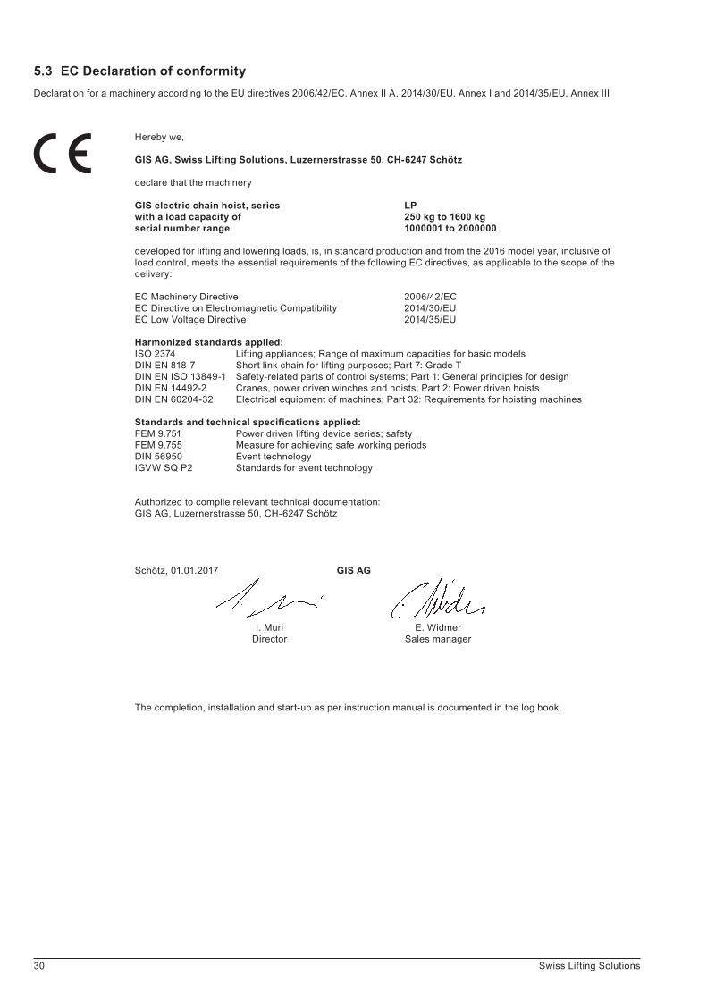
30 Swiss Lifting Solutions
Hereby we,
GIS AG, Swiss Lifting Solutions, Luzernerstrasse 50, CH-6247 Schötz
declare that the machinery
GIS electric chain hoist, series LPwith a load capacity of 250 kg to 1600 kgserial number range 1000001 to 2000000
developed for lifting and lowering loads, is, in standard production and from the 2016 model year, inclusive of load control, meets the essential requirements of the following EC directives, as applicable to the scope of the delivery:
EC Machinery Directive 2006/42/ECEC Directive on Electromagnetic Compatibility 2014/30/EUEC Low Voltage Directive 2014/35/EU
Harmonized standards applied:ISO 2374 Lifting appliances; Range of maximum capacities for basic modelsDIN EN 818-7 Short link chain for lifting purposes; Part 7: Grade TDIN EN ISO 13849-1 Safety-related parts of control systems; Part 1: General principles for designDIN EN 14492-2 Cranes, power driven winches and hoists; Part 2: Power driven hoistsDIN EN 60204-32 Electrical equipment of machines; Part 32: Requirements for hoisting machines
Standards and technical specifications applied:FEM 9.751 Power driven lifting device series; safetyFEM 9.755 Measure for achieving safe working periodsDIN 56950 Event technologyIGVW SQ P2 Standards for event technology
Authorized to compile relevant technical documentation:GIS AG, Luzernerstrasse 50, CH-6247 Schötz
Schötz, 01.01.2017 GIS AG
I. Muri E. Widmer Director Sales manager
The completion, installation and start-up as per instruction manual is documented in the log book.
Declaration for a machinery according to the EU directives 2006/42/EC, Annex II A, 2014/30/EU, Annex I and 2014/35/EU, Annex III
5.3 EC Declaration of conformity

31Swiss Lifting Solutions
Hereby we,
GIS AG, Swiss Lifting Solutions, Luzernerstrasse 50, CH-6247 Schötz
declare that the partly completed machinery
GIS electric chain hoist, series LPwith a load capacity of 250 kg to 1600 kgserial number range 1000001 to 2000000
developed for lifting and lowering loads, is, in standard production and from the 2016 model year, inclusive of load control, intended for installation in machinery and meets the essential requirements of the following EC directives, as applicable to the scope of the delivery:
EC Machinery Directive 2006/42/ECEC Directive on Electromagnetic Compatibility 2014/30/EUEC Low Voltage Directive 2014/35/EU
We also declare that the technical documentation has been compiled in accordance with Annex VII, Part B of Direc-tive 2006/42/EC. We undertake to submit the specific documents relating to the lifting device to national authorities on receipt of a reasonable request. The information will be supplied by electronic means.
Harmonized standards applied:ISO 2374 Lifting appliances; Range of maximum capacities for basic modelsDIN EN 818-7 Short link chain for lifting purposes; Part 7: Grade TDIN EN ISO 13849-1 Safety-related parts of control systems; Part 1: General principles for designDIN EN 14492-2 Cranes, power driven winches and hoists; Part 2: Power driven hoistsDIN EN 60204-32 Electrical equipment of machines; Part 32: Requirements for hoisting machines
Standards and technical specifications applied:FEM 9.751 Power driven lifting device series; safetyFEM 9.755 Measure for achieving safe working periodsDIN 56950 Event technologyIGVW SQ P2 Standards for event technology
This declaration only refers to the lifting device. A start-up is prohibited until it has been proven that the entire system where the lifting device is built in corresponds with the above EC Directives.
Authorized to compile relevant technical documentation:GIS AG, Luzernerstrasse 50, CH-6247 Schötz
Schötz, 01.01.2017 GIS AG
I. Muri E. Widmer Director Sales Manager
The completion, installation and start-up as per instruction manual is documented in the log book.
Declaration for the incorporation of a partly completed machinery according to the EU directives 2006/42/EC, Annex II B, 2014/30/EU, Annex I and 2014/35/EU, Annex III
5.4 EC Declaration of incorporation