Gates and Logic: From switches to Transistors , Logic Gates and Logic Circuits

Introduction to Computer
Engineering
CS/ECE 252, Spring 2013
Prof. Mark D. Hill
Computer Sciences Department
University of Wisconsin – Madison
Chapter 3
Digital Logic
Structures
Slides based on set prepared by
Gregory T. Byrd, North Carolina State University

Copyright © The McGraw-Hill Companies, Inc. Permission required for reproduction or display.
3-3
Transistor: Building Block of Computers
Microprocessors contain millions of transistors
• Intel Pentium II: 7 million
• Compaq Alpha 21264: 15 million
• Intel Pentium III: 28 million
Logically, each transistor acts as a switch
Combined to implement logic functions
• AND, OR, NOT
Combined to build higher-level structures
• Adder, multiplexer, decoder, register, …
Combined to build processor
• LC-3

Copyright © The McGraw-Hill Companies, Inc. Permission required for reproduction or display.
3-4
Simple Switch Circuit
Switch open:
• No current through circuit
• Light is off
• Vout is +2.9V
Switch closed:
• Short circuit across switch
• Current flows
• Light is on
• Vout is 0V
Switch-based circuits can easily represent two states:
on/off, open/closed, voltage/no voltage.

Copyright © The McGraw-Hill Companies, Inc. Permission required for reproduction or display.
3-5
N-type MOS Transistor
MOS = Metal Oxide Semiconductor
• two types: N-type and P-type
N-type
• when Gate has positive voltage,
short circuit between #1 and #2
(switch closed)
• when Gate has zero voltage,
open circuit between #1 and #2
(switch open) Gate = 1
Gate = 0
Terminal #2 must be
connected to GND (0V).

Copyright © The McGraw-Hill Companies, Inc. Permission required for reproduction or display.
3-6
P-type MOS Transistor
P-type is complementary to N-type
• when Gate has positive voltage,
open circuit between #1 and #2
(switch open)
• when Gate has zero voltage,
short circuit between #1 and #2
(switch closed)
Gate = 1
Gate = 0
Terminal #1 must be
connected to +2.9V.
Copyright © The McGraw-Hill Companies, Inc. Permission required for reproduction or display.
3-7
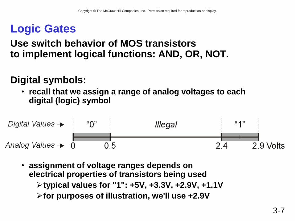
Logic Gates
Use switch behavior of MOS transistors to implement logical functions: AND, OR, NOT.
Digital symbols: • recall that we assign a range of analog voltages to each
digital (logic) symbol
• assignment of voltage ranges depends on electrical properties of transistors being used
typical values for "1": +5V, +3.3V, +2.9V, +1.1V
for purposes of illustration, we'll use +2.9V

Copyright © The McGraw-Hill Companies, Inc. Permission required for reproduction or display.
3-8
CMOS Circuit
Complementary MOS
Uses both N-type and P-type MOS transistors
• P-type
Attached to + voltage
Pulls output voltage UP when input is zero
• N-type
Attached to GND
Pulls output voltage DOWN when input is one
For all inputs, make sure that output is either connected to GND or to +,
but not both!

Copyright © The McGraw-Hill Companies, Inc. Permission required for reproduction or display.
3-9
Inverter (NOT Gate)
In Out
0 V 2.9 V
2.9 V 0 V
In Out
0 1
1 0
Truth table
Copyright © The McGraw-Hill Companies, Inc. Permission required for reproduction or display.
3-10
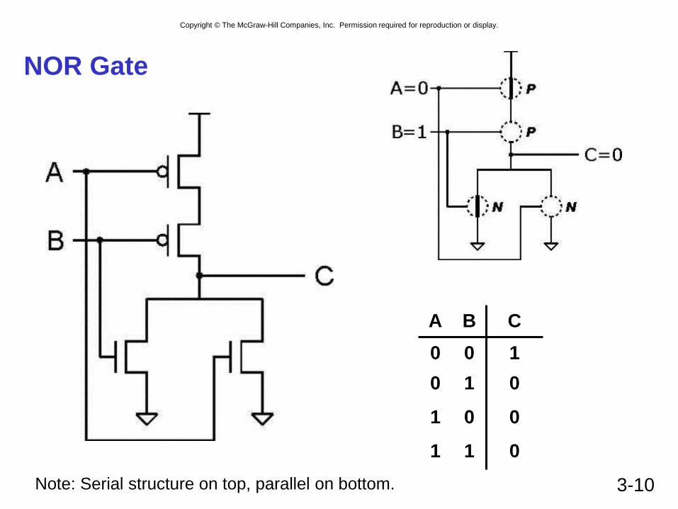
NOR Gate
A B C
0 0 1
0 1 0
1 0 0
1 1 0
Note: Serial structure on top, parallel on bottom.

Copyright © The McGraw-Hill Companies, Inc. Permission required for reproduction or display.
3-11
OR Gate
Add inverter to NOR.
A B C
0 0 0
0 1 1
1 0 1
1 1 1

Copyright © The McGraw-Hill Companies, Inc. Permission required for reproduction or display.
3-12
NAND Gate (AND-NOT)
A B C
0 0 1
0 1 1
1 0 1
1 1 0
Note: Parallel structure on top, serial on bottom.

Copyright © The McGraw-Hill Companies, Inc. Permission required for reproduction or display.
3-13
AND Gate
Add inverter to NAND.
A B C
0 0 0
0 1 0
1 0 0
1 1 1

Copyright © The McGraw-Hill Companies, Inc. Permission required for reproduction or display.
3-14
Basic Logic Gates

Copyright © The McGraw-Hill Companies, Inc. Permission required for reproduction or display.
3-15
More than 2 Inputs?
AND/OR can take any number of inputs.
• AND = 1 if all inputs are 1.
• OR = 1 if any input is 1.
• Similar for NAND/NOR.
Can implement with multiple two-input gates,
or with single CMOS circuit.

Copyright © The McGraw-Hill Companies, Inc. Permission required for reproduction or display.
3-16
Practice
Implement a 3-input NOR gate with CMOS.

Copyright © The McGraw-Hill Companies, Inc. Permission required for reproduction or display.
3-17
Logical Completeness
Can implement ANY truth table with AND, OR, NOT.
A B C D
0 0 0 0
0 0 1 0
0 1 0 1
0 1 1 0
1 0 0 0
1 0 1 1
1 1 0 0
1 1 1 0
1. AND combinations
that yield a "1" in the
truth table.
2. OR the results
of the AND gates.

Copyright © The McGraw-Hill Companies, Inc. Permission required for reproduction or display.
3-18
Practice
Implement the following truth table.
A B C
0 0 0
0 1 1
1 0 1
1 1 0
Copyright © The McGraw-Hill Companies, Inc. Permission required for reproduction or display.
3-19
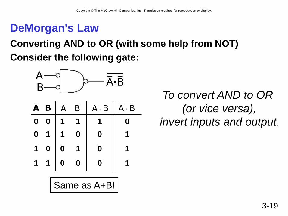
DeMorgan's Law
Converting AND to OR (with some help from NOT)
Consider the following gate:
A B
0 0 1 1 1 0
0 1 1 0 0 1
1 0 0 1 0 1
1 1 0 0 0 1
BA BA BA
Same as A+B!
To convert AND to OR
(or vice versa),
invert inputs and output.
Copyright © The McGraw-Hill Companies, Inc. Permission required for reproduction or display.
3-20
Summary
MOS transistors are used as switches to implement logic functions.
• N-type: connect to GND, turn on (with 1) to pull down to 0
• P-type: connect to +2.9V, turn on (with 0) to pull up to 1
Basic gates: NOT, NOR, NAND • Logic functions are usually expressed with AND, OR, and NOT
Properties of logic gates • Completeness
can implement any truth table with AND, OR, NOT
• DeMorgan's Law
convert AND to OR by inverting inputs and output

Copyright © The McGraw-Hill Companies, Inc. Permission required for reproduction or display.
3-21
Building Functions from Logic Gates
We've already seen how to implement truth tables using AND, OR, and NOT -- an example of combinational logic.
Combinational Logic Circuit • output depends only on the current inputs
• stateless
Sequential Logic Circuit • output depends on the sequence of inputs (past and present)
• stores information (state) from past inputs
We'll first look at some useful combinational circuits, then show how to use sequential circuits to store information.

Copyright © The McGraw-Hill Companies, Inc. Permission required for reproduction or display.
3-22
Decoder
n inputs, 2n outputs
• exactly one output is 1 for each possible input pattern
2-bit
decoder

Copyright © The McGraw-Hill Companies, Inc. Permission required for reproduction or display.
3-23
Multiplexer (MUX)
n-bit selector and 2n inputs, one output
• output equals one of the inputs, depending on selector
4-to-1 MUX

Copyright © The McGraw-Hill Companies, Inc. Permission required for reproduction or display.
3-24
Full Adder
Add two bits and carry-in,
produce one-bit sum and carry-out. A B Cin S Cout
0 0 0 0 0
0 0 1 1 0
0 1 0 1 0
0 1 1 0 1
1 0 0 1 0
1 0 1 0 1
1 1 0 0 1
1 1 1 1 1

Copyright © The McGraw-Hill Companies, Inc. Permission required for reproduction or display.
3-25
Four-bit Adder

Copyright © The McGraw-Hill Companies, Inc. Permission required for reproduction or display.
3-26
Combinational vs. Sequential
Combinational Circuit
• always gives the same output for a given set of inputs
ex: adder always generates sum and carry,
regardless of previous inputs
Sequential Circuit
• stores information
• output depends on stored information (state) plus input
so a given input might produce different outputs,
depending on the stored information
• example: ticket counter
advances when you push the button
output depends on previous state
• useful for building “memory” elements and “state machines”

Copyright © The McGraw-Hill Companies, Inc. Permission required for reproduction or display.
3-27
R-S Latch: Simple Storage Element
R is used to “reset” or “clear” the element – set it to zero.
S is used to “set” the element – set it to one.
If both R and S are one, out could be either zero or one.
• “quiescent” state -- holds its previous value
• note: if a is 1, b is 0, and vice versa
1
0
1
1
1
1
0
0
1
1
0
0
1
1

Copyright © The McGraw-Hill Companies, Inc. Permission required for reproduction or display.
3-28
Clearing the R-S latch
Suppose we start with output = 1, then change R to zero.
Output changes to zero.
Then set R=1 to “store” value in quiescent state.
1
0
1
1
1
1
0
0
1
0
1
0
0
0
1
1

Copyright © The McGraw-Hill Companies, Inc. Permission required for reproduction or display.
3-29
Setting the R-S Latch
Suppose we start with output = 0, then change S to zero.
Output changes to one.
Then set S=1 to “store” value in quiescent state.
1
1
0
0
1
1
0
1
1
1
0
0
Copyright © The McGraw-Hill Companies, Inc. Permission required for reproduction or display.
3-30
R-S Latch Summary
R = S = 1
• hold current value in latch
S = 0, R=1
• set value to 1
R = 0, S = 1
• set value to 0
R = S = 0
• both outputs equal one
• final state determined by electrical properties of gates
• Don’t do it!

Copyright © The McGraw-Hill Companies, Inc. Permission required for reproduction or display.
3-31
Gated D-Latch
Two inputs: D (data) and WE (write enable)
• when WE = 1, latch is set to value of D
S = NOT(D), R = D
• when WE = 0, latch holds previous value
S = R = 1
Copyright © The McGraw-Hill Companies, Inc. Permission required for reproduction or display.
3-32
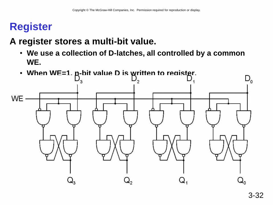
Register
A register stores a multi-bit value.
• We use a collection of D-latches, all controlled by a common
WE.
• When WE=1, n-bit value D is written to register.

Copyright © The McGraw-Hill Companies, Inc. Permission required for reproduction or display.
3-33
Representing Multi-bit Values
Number bits from right (0) to left (n-1)
• just a convention -- could be left to right, but must be consistent
Use brackets to denote range:
D[l:r] denotes bit l to bit r, from left to right
May also see A<14:9>,
especially in hardware block diagrams.
A = 0101001101010101
A[2:0] = 101 A[14:9] = 101001
0 15

Copyright © The McGraw-Hill Companies, Inc. Permission required for reproduction or display.
3-34
Memory
Now that we know how to store bits,
we can build a memory – a logical k × m array of
stored bits.
• • •
k = 2n
locations
m bits
Address Space:
number of locations (usually a power of 2)
Addressability:
number of bits per location (e.g., byte-addressable)
Copyright © The McGraw-Hill Companies, Inc. Permission required for reproduction or display.
3-35
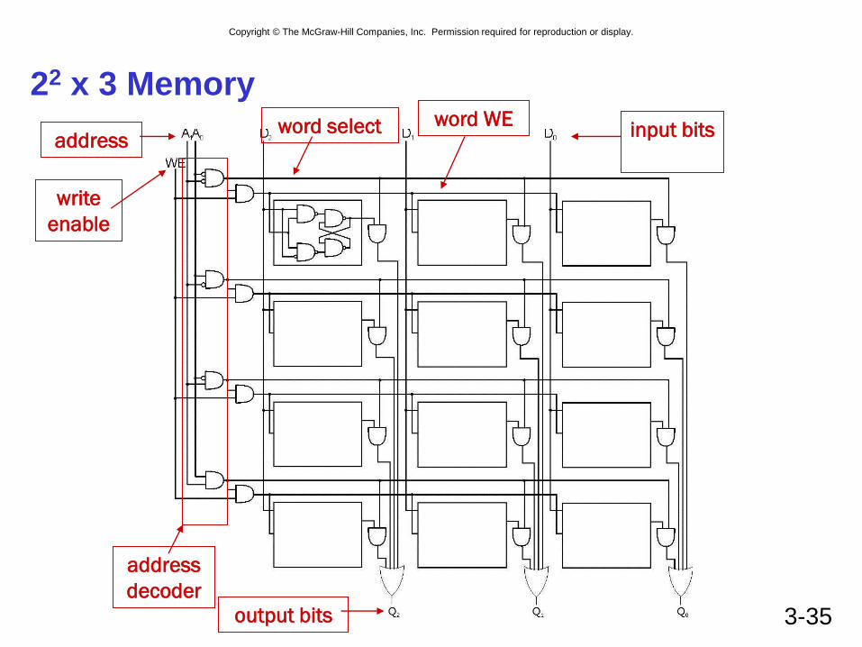
22 x 3 Memory
address
decoder
word select word WE address
write
enable
input bits
output bits

Copyright © The McGraw-Hill Companies, Inc. Permission required for reproduction or display.
3-36
More Memory Details
This is a not the way actual memory is implemented.
• fewer transistors, much more dense,
relies on electrical properties
But the logical structure is very similar.
• address decoder
• word select line
• word write enable
Two basic kinds of RAM (Random Access Memory)
Static RAM (SRAM)
• fast, maintains data without power
Dynamic RAM (DRAM)
• slower but denser, bit storage must be periodically refreshed
Also, non-volatile memories: ROM, PROM, flash, …

Copyright © The McGraw-Hill Companies, Inc. Permission required for reproduction or display.
3-37
State Machine
Another type of sequential circuit
• Combines combinational logic with storage
• “Remembers” state, and changes output (and state)
based on inputs and current state
State Machine
Combinational
Logic Circuit
Storage
Elements
Inputs Outputs

Copyright © The McGraw-Hill Companies, Inc. Permission required for reproduction or display.
3-38
Combinational vs. Sequential
Two types of “combination” locks
4 1 8 4
30
15
5
10 20
25
Combinational
Success depends only on
the values, not the order in
which they are set.
Sequential
Success depends on
the sequence of values
(e.g, R-13, L-22, R-3).

Copyright © The McGraw-Hill Companies, Inc. Permission required for reproduction or display.
3-39
State
The state of a system is a snapshot of
all the relevant elements of the system
at the moment the snapshot is taken.
Examples:
• The state of a basketball game can be represented by
the scoreboard.
Number of points, time remaining, possession, etc.
• The state of a tic-tac-toe game can be represented by
the placement of X’s and O’s on the board.

Copyright © The McGraw-Hill Companies, Inc. Permission required for reproduction or display.
3-40
State of Sequential Lock
Our lock example has four different states,
labelled A-D:
A: The lock is not open,
and no relevant operations have been performed.
B: The lock is not open,
and the user has completed the R-13 operation.
C: The lock is not open,
and the user has completed R-13, followed by L-22.
D: The lock is open.

Copyright © The McGraw-Hill Companies, Inc. Permission required for reproduction or display.
3-41
State Diagram
Shows states and
actions that cause a transition between states.

Copyright © The McGraw-Hill Companies, Inc. Permission required for reproduction or display.
3-42
Finite State Machine
A description of a system with the following components:
1. A finite number of states
2. A finite number of external inputs
3. A finite number of external outputs
4. An explicit specification of all state transitions
5. An explicit specification of what causes each
external output value.
Often described by a state diagram.
• Inputs may cause state transitions.
• Outputs are associated with each state (or with each transition).

Copyright © The McGraw-Hill Companies, Inc. Permission required for reproduction or display.
3-43
The Clock
Frequently, a clock circuit triggers transition from
one state to the next.
At the beginning of each clock cycle,
state machine makes a transition,
based on the current state and the external inputs.
• Not always required. In lock example, the input itself triggers a transition.
“1”
“0”
time One
Cycle

Copyright © The McGraw-Hill Companies, Inc. Permission required for reproduction or display.
3-44
Implementing a Finite State Machine
Combinational logic
• Determine outputs and next state.
Storage elements
• Maintain state representation.
State Machine
Combinational
Logic Circuit
Storage
Elements
Inputs Outputs
Clock

Copyright © The McGraw-Hill Companies, Inc. Permission required for reproduction or display.
3-45
Storage: Master-Slave Flipflop
A pair of gated D-latches,
to isolate next state from current state.
During 1st phase (clock=1),
previously-computed state
becomes current state and is
sent to the logic circuit.
During 2nd phase (clock=0),
next state, computed by
logic circuit, is stored in
Latch A.

Copyright © The McGraw-Hill Companies, Inc. Permission required for reproduction or display.
3-46
Storage
Each master-slave flipflop stores one state bit.
The number of storage elements (flipflops) needed
is determined by the number of states
(and the representation of each state).
Examples:
• Sequential lock
Four states – two bits
• Basketball scoreboard
7 bits for each score, 5 bits for minutes, 6 bits for seconds,
1 bit for possession arrow, 1 bit for half, …

Copyright © The McGraw-Hill Companies, Inc. Permission required for reproduction or display.
3-47
Complete Example
A blinking traffic sign
• No lights on
• 1 & 2 on
• 1, 2, 3, & 4 on
• 1, 2, 3, 4, & 5 on
• (repeat as long as switch
is turned on)
DANGER MOVE
RIGHT
1
2
3
4
5

Copyright © The McGraw-Hill Companies, Inc. Permission required for reproduction or display.
3-48
Traffic Sign State Diagram
State bit S1 State bit S0
Switch on
Switch off
Outputs
Transition on each clock cycle.

Copyright © The McGraw-Hill Companies, Inc. Permission required for reproduction or display.
3-49
Traffic Sign Truth Tables
Outputs
(depend only on state: S1S0)
S1 S0 Z Y X
0 0 0 0 0
0 1 1 0 0
1 0 1 1 0
1 1 1 1 1
Lights 1 and 2
Lights 3 and 4
Light 5
Next State: S1’S0’
(depend on state and input)
In S1 S0 S1’ S0’
0 X X 0 0
1 0 0 0 1
1 0 1 1 0
1 1 0 1 1
1 1 1 0 0
Switch
Whenever In=0, next state is 00.

Copyright © The McGraw-Hill Companies, Inc. Permission required for reproduction or display.
3-50
Traffic Sign Logic
Master-slave
flipflop

Copyright © The McGraw-Hill Companies, Inc. Permission required for reproduction or display.
3-51
From Logic to Data Path
The data path of a computer is all the logic used to
process information.
• See the data path of the LC-2 on next slide.
Combinational Logic
• Decoders -- convert instructions into control signals
• Multiplexers -- select inputs and outputs
• ALU (Arithmetic and Logic Unit) -- operations on data
Sequential Logic
• State machine -- coordinate control signals and data movement
• Registers and latches -- storage elements

Copyright © The McGraw-Hill Companies, Inc. Permission required for reproduction or display.
3-52
LC-2/LC-3 Data Path