Transient Stability Analysis of Generation and ......sudden load changes and various faults. In this...
18
International Journal of Scientific & Engineering Research, Volume 7, Issue 5, May-2016 1543 ISSN 2229-5518 IJSER © 2016 http://www.ijser.org Transient Stability Analysis of Generation and Transmission system of a thermal power plant of Pakistan. Izhar Ahmad University of Engineering and Technology Peshawar, Khyber Pakhtunkhwa, Pakistan. Email: [email protected] Dr.Amjad Ullah Faculty Member Electrical Engineering, Department of Electrical Engineering, University of Engineering and Technology, Peshawar, Khyber Pakhtunkhwa, Pakistan Email: [email protected] Abstract: Power system is exposing to various unexpected conditions, which may involve different kinds of faults and sudden load changes. The main reason of these unexpected conditions within power system is its larger size and complicated structure. These accidental conditions may lead to unexpected behavior of power system which may causes instability within the system. The power system must regain its stability after being exposed to various disturbances such as sudden load changes and various faults. In this research paper, the transient stability analysis of generation and high- voltage transmission system of a thermal power plant in Pakistan is performed and analyzed using ETAP software. Three- phase faults are created/developed at different locations and after that, sudden load changed. Transient stability of the system has assessed from the analysis of various system parameters and critical clearing time of the system transients. NOTE.NPCC (National Power Control Center), WAPDA (Water and Power Development Authority) —————————— —————————— 1. Introduction The desirable operation of any power system is to maintain synchronism and equilibrium between different parts of system and generating units after being subjected to transients. There may be great risk of losing synchronization any time between generating units, and system becomes unstable after transients. The two major types of stabilities are transient stability and steady-state stability [1]. Steady-state stability is the ability of a power system to maintain synchronism and equilibrium after gradual disturbances. Transient stability is the ability of a power system to maintain synchronism and equilibrium after large disturbances. To find out the system withstanding ability to transients, transient stability analysis must be performed [2]. Transient stability is the dominant stability problem and has been considered much of the attention regarding power system stability [3]. The main purpose of transient stability analysis is to find that whether the system regains its equilibrium after the disturbances. The system planners and operators have a great interest in recovery of a power system from disturbances. The system design should be such that it continuously provides electrical power to utilities without losing stability after being subjected to transients [4]. Transients, such as transmission system faults and sudden load changes, stress the power system in many ways and produce various effects such as frequency transients, voltage and current transients, and inter area oscillations or power swing. For a power system to be stable, all these effects last only for a finite period of time [3]. The system may be stable or unstable after disturbance, depending upon the duration and location of disturbance [5]. Selection of proper protective devices and their rating & specifications is a function of system transient behavior because during transient, the parameters of the system changes largely. If the parameters such as voltage, current and power are IJSER
Transcript of Transient Stability Analysis of Generation and ......sudden load changes and various faults. In this...

International Journal of Scientific & Engineering Research, Volume 7, Issue 5, May-2016 1543 ISSN 2229-5518
IJSER © 2016 http://www.ijser.org
Transient Stability Analysis of Generation and Transmission system of a thermal
power plant of Pakistan. Izhar Ahmad
University of Engineering and Technology Peshawar, Khyber Pakhtunkhwa, Pakistan. Email: [email protected]
Dr.Amjad Ullah Faculty Member Electrical Engineering, Department of Electrical Engineering, University of Engineering and
Technology, Peshawar, Khyber Pakhtunkhwa, Pakistan Email: [email protected]
Abstract: Power system is exposing to various unexpected conditions, which may involve different kinds of faults and sudden load changes. The main reason of these unexpected conditions within power system is its larger size and complicated structure. These accidental conditions may lead to unexpected behavior of power system which may causes instability within the system. The power system must regain its stability after being exposed to various disturbances such as sudden load changes and various faults. In this research paper, the transient stability analysis of generation and high-voltage transmission system of a thermal power plant in Pakistan is performed and analyzed using ETAP software. Three-phase faults are created/developed at different locations and after that, sudden load changed. Transient stability of the system has assessed from the analysis of various system parameters and critical clearing time of the system transients.
NOTE.NPCC (National Power Control Center), WAPDA (Water and Power Development Authority)
—————————— —————————— 1. Introduction
The desirable operation of any power system is to maintain synchronism and equilibrium between different parts of system and generating units after being subjected to transients. There may be great risk of losing synchronization any time between generating units, and system becomes unstable after transients. The two major types of stabilities are transient stability and steady-state stability [1].
Steady-state stability is the ability of a power system to maintain synchronism and equilibrium after gradual disturbances. Transient stability is the ability of a power system to maintain synchronism and equilibrium after large disturbances. To find out the system withstanding ability to transients, transient stability analysis must be performed [2].
Transient stability is the dominant stability problem and has been considered much of the attention regarding power system stability [3]. The main purpose of transient stability analysis is to find that whether the system regains its equilibrium after the
disturbances. The system planners and operators have a great interest in recovery of a power system from disturbances. The system design should be such that it continuously provides electrical power to utilities without losing stability after being subjected to transients [4].
Transients, such as transmission system faults and sudden load changes, stress the power system in many ways and produce various effects such as frequency transients, voltage and current transients, and inter area oscillations or power swing. For a power system to be stable, all these effects last only for a finite period of time [3]. The system may be stable or unstable after disturbance, depending upon the duration and location of disturbance [5].
Selection of proper protective devices and their rating & specifications is a function of system transient behavior because during transient, the parameters of the system changes largely. If the parameters such as voltage, current and power are
IJSER
International Journal of Scientific & Engineering Research, Volume 7, Issue 5, May-2016 1544 ISSN 2229-5518
IJSER © 2016 http://www.ijser.org
same before fault and after fault, the system will be stable [6].
Transients on a power system lead to variation in power flows, network bus voltages and machines rotor speeds. For a given disturbance, the system may be stable or unstable depending upon disturbance. If a generator remain stable after a disturbance, it may adopt a new state of equilibrium and for that machine, stability conditions will be different from that of previous one [7].
Different forms of system stabilities are frequency-stability, voltage-stability and rotor angle stability. If power system maintain steady voltages at all busses after disturbance then it is called voltage-stability. If power system maintains steady frequency after disturbance then it is called frequency-stability. Rotor angle stability is the ability of synchronous machines to maintain synchronism after disturbance [7].
During transient, the shaft of generator accelerates and decelerates periodically and hence its energy output oscillates with a sinusoidal manner, as a result output electrical power and load angle oscillate in the same manner. In equilibrium point, the mechanical torque is equal to output electrical torque and the system is said to be stable [9].
Authors in [1] have performed transient stability analysis of Tamilnado Generation and transmission
line system. The single-line diagram of the mentioned area is created/developed in ETAP software. A three-phase fault is created at some specified bus and as a result of that critical clearing time of transient is studied. Finally transient stability is assessed from rate of change of system frequency, power angle and voltage levels of the busses.
Authors in [2] have performed transient stability analysis of IEEE 9 bus system. A three phase fault is created at different locations, the effect of fault on the system and critical clearing time on the system stability is analyzed.
Various methods are used for transient stability analysis of a power system. In this research paper, the tool used for analysis and simulation are Electrical Transient and Analysis Program (ETAP). Single line diagram of generation and transmission system of a thermal power plant in Mianwali, Pakistan is created/developed, simulated and analyzed in ETAP software for different system transient conditions such as three-phase faults at different locations and sudden load changing. The total duration of transient period, frequency transients, voltage and current transients, power swing and rotor angles are analyzed. Transient stability of the power system of the mentioned area is assessed using these system conditions.
3. Modeling of the system
The single line diagram of the mentioned area is modeled in ETAP as shown in figure. ETAP is chosen as simulation software for transient stability analysis for most of the industrial power system.
The system consists of two main generators, rated 325MW and 340MW. Both generators are
connected to a common switchyard after 370MVA and 400MVA transformers respectively. The power of these generating units is transmitted to two separate grid stations naming Daudkhel grid and Ludewala grid at distance of 70km and 125km respectively from generating units as shown in figure. Jinnah Hydal power plant is a small
IJSER

International Journal of Scientific & Engineering Research, Volume 7, Issue 5, May-2016 1545 ISSN 2229-5518
IJSER © 2016 http://www.ijser.org
generating plant delivering 40MW of power (depending upon requirement) to Daudkhel grid station. Ludewala grid station is also connected to Mangla power house. Mangla gives 30-40 MW power (depending upon requirement) to Ludewala grid station.
The important data about load flow, transmission lines, rating and specification of busses and
equipment’s has collected from WAPDA and NPCC.
The single-line diagram of the mentioned area is shown in figure below.
Figure 1: single line diagram of Generation and Transmission system of understudy Thermal Power Plant
4. Transient stability analysis
Transient stability analysis is performed for finding the ability of the mentioned system to regain its
steady-state equilibrium state after clearance of disturbances. The purpose is to find the severity of
IJSER
International Journal of Scientific & Engineering Research, Volume 7, Issue 5, May-2016 1546 ISSN 2229-5518
IJSER © 2016 http://www.ijser.org
disturbances, and also it is found that how much the system is affected by the disturbances. The system behavior is checked by the transient stability analysis by exposing the system to disturbances of three-phase faults at different locations and sudden
load changing. There are restricted stability boundaries within which the system supposed to be stable, if those boundaries is crossed, the system becomes instable.
4.1. Three phase fault at different location
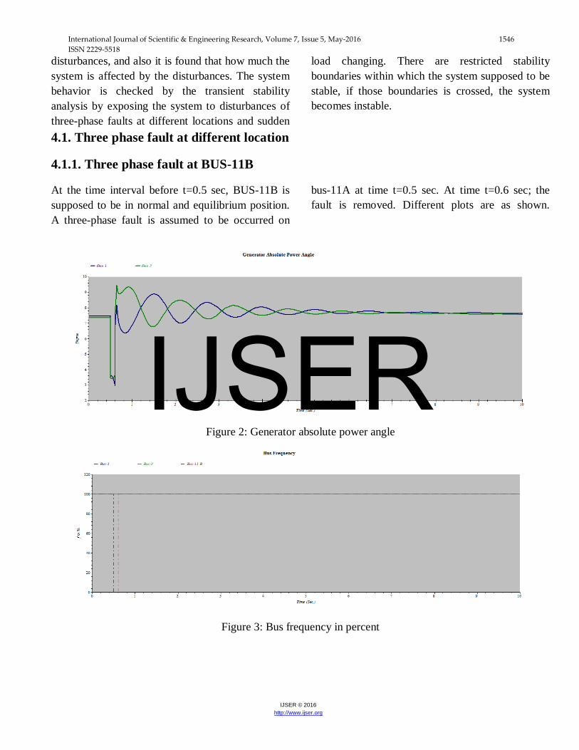
4.1.1. Three phase fault at BUS-11B
At the time interval before t=0.5 sec, BUS-11B is supposed to be in normal and equilibrium position. A three-phase fault is assumed to be occurred on
bus-11A at time t=0.5 sec. At time t=0.6 sec; the fault is removed. Different plots are as shown.
Figure 2: Generator absolute power angle
Figure 3: Bus frequency in percent
IJSER
International Journal of Scientific & Engineering Research, Volume 7, Issue 5, May-2016 1547 ISSN 2229-5518
IJSER © 2016 http://www.ijser.org
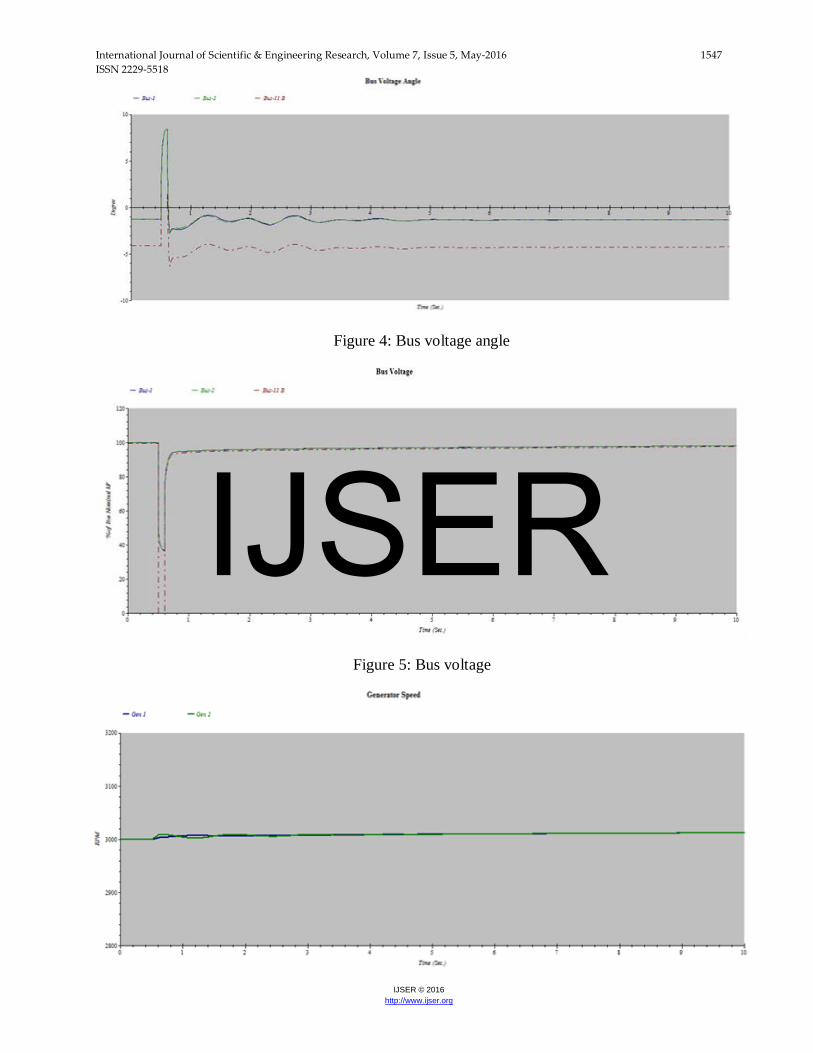
Figure 4: Bus voltage angle
Figure 5: Bus voltage
IJSER

International Journal of Scientific & Engineering Research, Volume 7, Issue 5, May-2016 1548 ISSN 2229-5518
IJSER © 2016 http://www.ijser.org
Figure 6: Generator speed.
Figure 7: Generator terminal current
Figure 8: Generator electrica power
IJSER

International Journal of Scientific & Engineering Research, Volume 7, Issue 5, May-2016 1549 ISSN 2229-5518
IJSER © 2016 http://www.ijser.org
Figure 9: Generator relative power angle
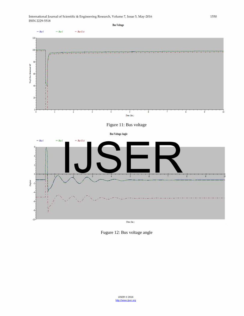
4.1.2. Three phase fault at BUS-12A
At the time interval before t=0.5 sec, BUS-12A is supposed to be in normal and equilibrium position. A three-phase fault is assumed to be occurred on
bus-11A at time t=0.5 sec. At time t=0.6 sec, the fault is removed. Different plots are as shown.
Figure 10: Bus frequency
IJSER
International Journal of Scientific & Engineering Research, Volume 7, Issue 5, May-2016 1550 ISSN 2229-5518
IJSER © 2016 http://www.ijser.org
Figure 11: Bus voltage
Fugure 12: Bus voltage angle
IJSER
International Journal of Scientific & Engineering Research, Volume 7, Issue 5, May-2016 1551 ISSN 2229-5518
IJSER © 2016 http://www.ijser.org
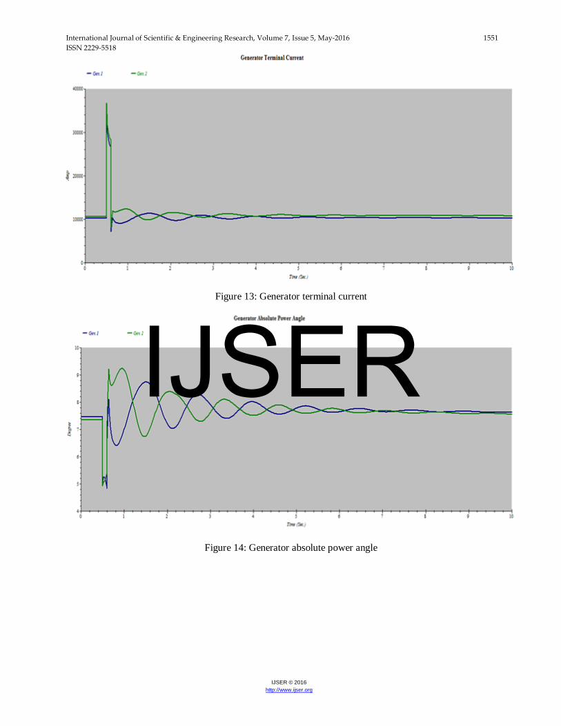
Figure 13: Generator terminal current
Figure 14: Generator absolute power angle
IJSER
International Journal of Scientific & Engineering Research, Volume 7, Issue 5, May-2016 1552 ISSN 2229-5518
IJSER © 2016 http://www.ijser.org
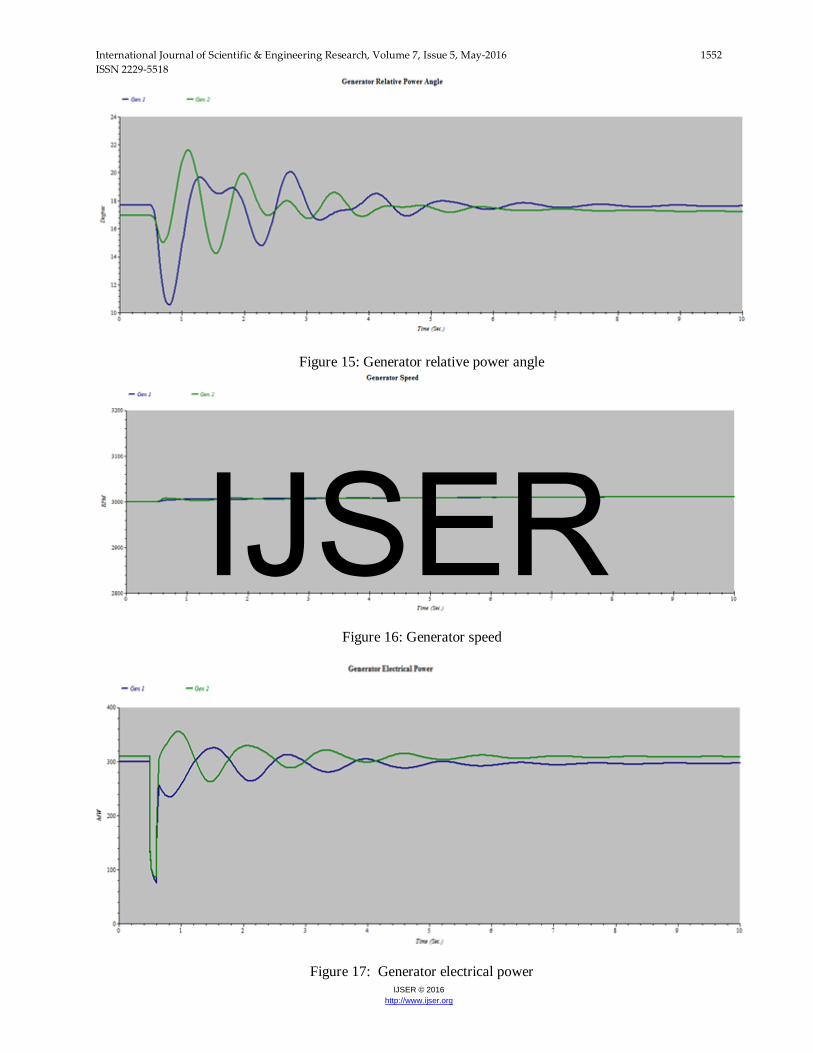
Figure 15: Generator relative power angle
Figure 16: Generator speed
Figure 17: Generator electrical power
IJSER

International Journal of Scientific & Engineering Research, Volume 7, Issue 5, May-2016 1553 ISSN 2229-5518
IJSER © 2016 http://www.ijser.org
From the above waveforms it is clear that the system regains its stability after clearance of fault at time t=7 sec. The faulty bus has zero voltage and frequency at the time of fault and comes back to normal voltage and frequency after clearance of fault as shown in figures 3, 10,5,11.
The regular generator current of generator 1 and generator 2 at pre-fault is 10500 and 11000 ampere. During fault, the current is about five times higher than normal currents. The generator currents regain their normal values after the clearance of fault as shown in figure 7,13.
At the time of fault, the rotor angles of generators severely disturbed. The equilibrium is upset
between electrical and mechanical torque because of which some machines temporarily run faster and some runs slower causing the power swing between generators as shown in figure 8, 17. At time t=7 or 8 sec, after disturbance, the equilibrium is restored and the system regains its steady-state operation as shown in figure 2, 9, 14, 15.
Disturbances in the power system cause variation in generator RPM also. At time t=0.5 sec, the RPM of generators disturbed, the rotors of some of the generators accelerate and some decelerate. At time t=7 0r 8 sec, the rotor steady down to its equilibrium position and the system achieves its steady-state operation. The system is said to be stable at time t=7 sec.
4.1.3 Three phase fault at transmission lines
At the time interval before t=0.7 sec, there is no fault on transmission line. A three-phase fault is assumed to be occurred on transmission line at time t=0.7 sec. At time t=0.8 sec; the fault is cleared.
Different plots as a result of disturbance are as shown below.
Figure 18: Bus frequency
IJSER
International Journal of Scientific & Engineering Research, Volume 7, Issue 5, May-2016 1554 ISSN 2229-5518
IJSER © 2016 http://www.ijser.org
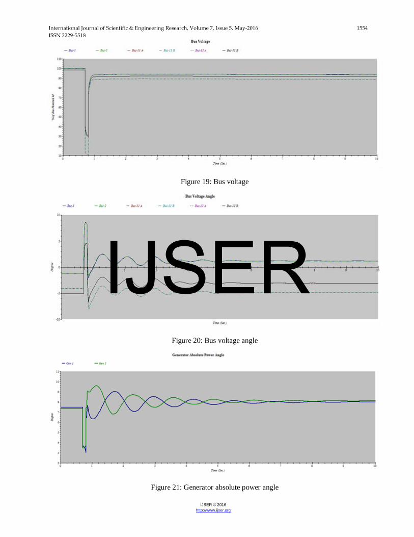
Figure 19: Bus voltage
Figure 20: Bus voltage angle
Figure 21: Generator absolute power angle
IJSER
International Journal of Scientific & Engineering Research, Volume 7, Issue 5, May-2016 1555 ISSN 2229-5518
IJSER © 2016 http://www.ijser.org
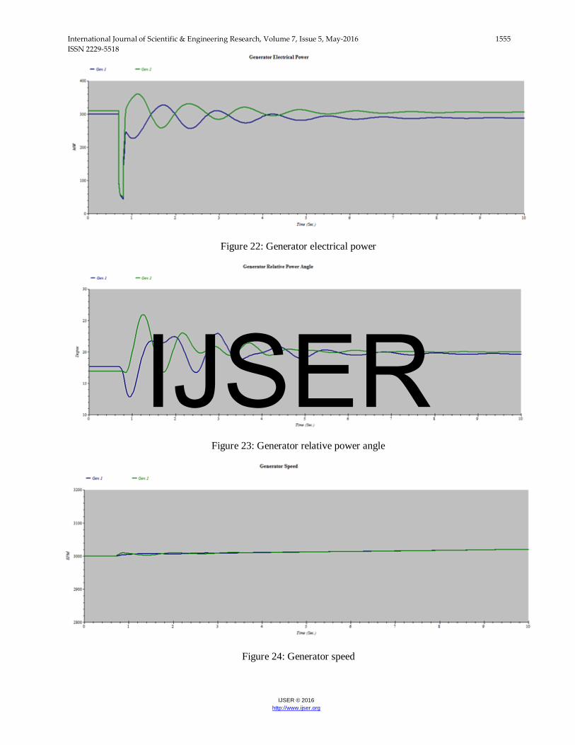
Figure 22: Generator electrical power
Figure 23: Generator relative power angle
Figure 24: Generator speed
IJSER
International Journal of Scientific & Engineering Research, Volume 7, Issue 5, May-2016 1556 ISSN 2229-5518
IJSER © 2016 http://www.ijser.org
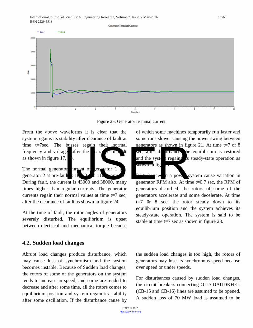
Figure 25: Generator terminal current
From the above waveforms it is clear that the system regains its stability after clearance of fault at time t=7sec. The busses regain their normal frequency and voltages after the clearance of fault as shown in figure 17, 18.
The normal generator current of generator 1 and generator 2 at pre-fault is 10500 and 11000 ampere. During fault, the current is 43000 and 38000, many times higher than regular currents. The generator currents regain their normal values at time t=7 sec, after the clearance of fault as shown in figure 24.
At the time of fault, the rotor angles of generators severely disturbed. The equilibrium is upset between electrical and mechanical torque because
of which some machines temporarily run faster and some runs slower causing the power swing between generators as shown in figure 21. At time t=7 or 8 sec, after disturbance, the equilibrium is restored and the system regains its steady-state operation as shown in figures.
Disturbances in a power system cause variation in generator RPM also. At time t=0.7 sec, the RPM of generators disturbed, the rotors of some of the generators accelerate and some decelerate. At time t=7 0r 8 sec, the rotor steady down to its equilibrium position and the system achieves its steady-state operation. The system is said to be stable at time t=7 sec as shown in figure 23.
4.2. Sudden load changes
Abrupt load changes produce disturbance, which may cause loss of synchronism and the system becomes instable. Because of Sudden load changes, the rotors of some of the generators on the system tends to increase in speed, and some are tended to decrease and after some time, all the rotors comes to equilibrium position and system regain its stability after some oscillation. If the disturbance cause by
the sudden load changes is too high, the rotors of generators may lose its synchronous speed because over speed or under speeds.
For disturbances caused by sudden load changes, the circuit breakers connecting OLD DAUDKHEL (CB-15 and CB-16) lines are assumed to be opened. A sudden loss of 70 MW load is assumed to be
IJSER
International Journal of Scientific & Engineering Research, Volume 7, Issue 5, May-2016 1557 ISSN 2229-5518
IJSER © 2016 http://www.ijser.org
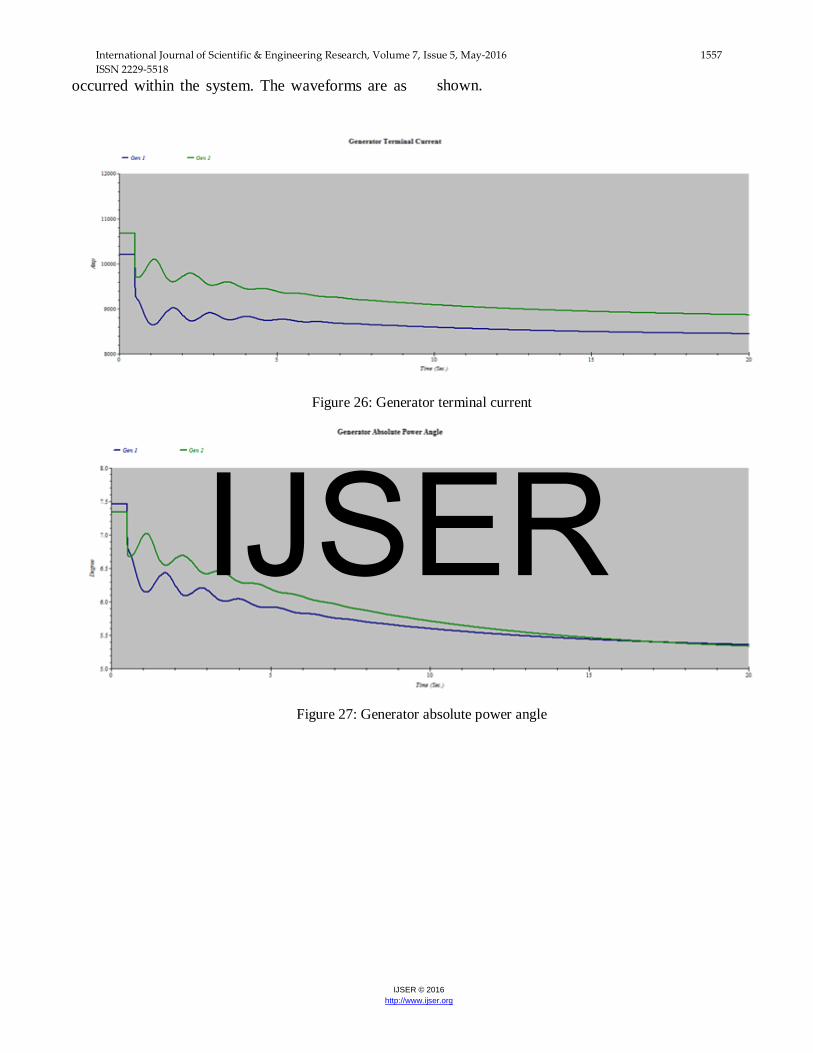
occurred within the system. The waveforms are as shown.
Figure 26: Generator terminal current
Figure 27: Generator absolute power angle
IJSER
International Journal of Scientific & Engineering Research, Volume 7, Issue 5, May-2016 1558 ISSN 2229-5518
IJSER © 2016 http://www.ijser.org
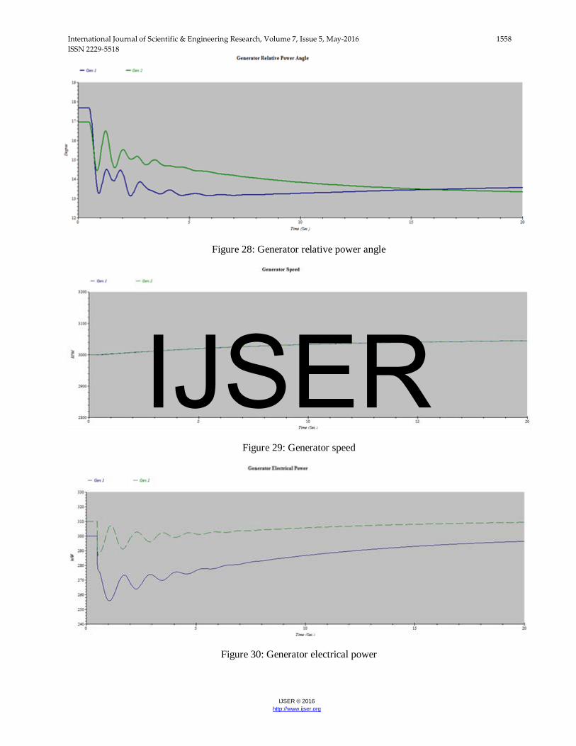
Figure 28: Generator relative power angle
Figure 29: Generator speed
Figure 30: Generator electrical power
IJSER
International Journal of Scientific & Engineering Research, Volume 7, Issue 5, May-2016 1559 ISSN 2229-5518
IJSER © 2016 http://www.ijser.org
From the above waveforms it is clear that the system regains its stability after disturbance at time t=15 sec.
The normal generator current of generator 1 and generator 2 before disturbance is 10500 and 11000 ampere. When sudden load loss occurs, the generator currents also decrease after some transients as shown in figure 25.
At the time of sudden loss of load, the rotor angles of generators severely disturbed. The equilibrium is upset between electrical and mechanical torque because of which some machines temporarily run
faster and some runs slower causing the power swing between generators as shown in figure 29. At time t=15 sec, after disturbance, the equilibrium is restored and the system regains its steady-state operation as shown in figure 26, 27.
Disturbances in a power system cause variation in generator RPM also. At time t=0.5 sec, the RPM of generators disturbed, the rotors of some of the generators accelerate and some decelerate. At time t=15 sec, the rotor steady down to its equilibrium position and the system achieves its steady-state operation. The system is said to be stable at time t=15 sec.
5. Conclusion
In this research paper, transient stability of generation and transmission system of a thermal power plant in district Mianwali, Pakistan has been studied. The parameters such as rate of change of system frequency, power angle, bus voltage levels, current levels of each generator and power swings are considered for analysis. The performance of the proposed system has been analyzed in ETAP software. The recovery time of the power system from transient (the critical clearing time) and effects caused by the faults has been studied from transient
stability analysis. The system transient stability assessed with the aforementioned system information. This research work helps to find the ratings and specifications of protective equipment’s for any type of transients. This research work is useful in future expansion planning, designing and up gradation of power system and gives an important data for system operators, planners and designers.
References
[1] Monica A and Dr. Narayanappa, “Transient stability analysis of TNGT power system," IEEE 8th Proceedings international conference on intelligent system and control (ISCO, 2014), Page 149-154 Coimbatore, 10-11 Jan 2014.
[2] Swaroop Kumar.Nallagalva, Mukesh Kumar Kirar, Dr.Ganga Agnihotri, “Transient Stability Analysis of the IEEE 9-Bus Electric Power System,”
International Journal of Scientific Engineering and Technology, Volume No.1, Issue No.3, pg. 161- 166, July 2012.
[3] Probha Kundur, Jhon Paserba, Venkat Ajjarapu and Anjan bose, “Definition and classification of power system stability,” IEEE Transactions on power system, Vol. 19, NO. 2, Page 1387-1401, Aug 2004.
[4] Pushp raj, “Load Flow and Short Circuit Analysis of 400/220 Kv Substation,” International Journal of Creative Research Thoughts, vol. 1, Issue. 5, April 2013.
[5] Masayuki Watanabe, Yasunori Mitani, Hiroyuki, Yoshihisa Uriu and Yasuhiro Urano, “Transient stability assessment of industrial power systems with detailed model implementation,”
IJSER

International Journal of Scientific & Engineering Research, Volume 7, Issue 5, May-2016 1560 ISSN 2229-5518
IJSER © 2016 http://www.ijser.org
Industry Applications Society Annual Meeting (IAS), 2011 IEEE, page 1-6 ,Orlando, FL,9-13 Oct. 2011
[6] K.B. Porate and Shital C. Gabhane, “Transient Analysis of 220KV Distribution Substation: A Case study,” Third International Conference on Emerging Trends in Engineering and Technology," Page(s) 385-389 Goa, 19-21 Nov 2010
[7] Prabha Kundur and co, “Definition and classification of power system stability IEEE/CIGRE joint task force on stability terms and definitions,” IEEE Transactions on Power Systems (Volume: 19, Issue: 3), page 1387 - 1401, Aug 2004.
[8] Roman Kuiava,Rodrigo A. Ramos, Luis F. C. Alberto,Hemanshu R. Pota, “Practical Stability Assessement of Distributed Synchronous Generators Under Load Variations,” IEEE International Symposium on Circuits and Systems (ISCAS2013),page 457-460,Beijing, 19-23 may 2013.
[9] Christian Romeis, Johann Jaeger, “Active Damping of Power Swings in Bulk Power Transmission Systems,” Power System Technology (POWERCON), 2012 IEEE International Conference, Page1-4, Auckland, Oct. 30 2012-Nov.2 2012
[10] P. Kundur, Power System Stability and Control, New York: Mc Graw-Hill, 1994 pp 104-120
[11] N.Peru mal and Aliza Che Amran,“Automatic load shedding in power system,” National power and energy conference(PEC) 2003 proceedings, Bangi Malasia, Page 211-216, 15-16 Dec 2003
IJSER