Fine-Grained Mobility Characterization: Steady and Transient State Behaviors
Journal of ELECTRICAL ENGINEERING, VOL 68 (2017), NO1, 31–38
Transient and steady state performance analysis of powerflow control in a DFIG variable speed wind turbine
Cajethan M. Nwosu, Stephen E. Oti, Cosmas U. Ogbuka∗
This paper presents transient and steady state performance analysis of power flow control in a 5.0 kW Doubly-FedInduction Generator (DFIG) Variable Speed Wind Turbine (VSWT) under sub synchronous speed, super synchronous speedand synchronous speed modes of operation. Stator flux orientation is used for the control of the rotor-side converter (RSC)and DFIG whereas the grid (or stator) voltage orientation is the preferred choice for the control of the grid-side converter(GSC). In each of the three speeds modes, power is always supplied to the grid through the stator of the DFIG. Themagnitude of net power (stator power plus rotor power) is less than stator power during the sub synchronous speed mode;it is greater than stator power during the super synchronous speed mode while it is equal to the stator power during thesynchronous speed mode. In synchronous speed mode, the rotor power is zero indicating that power is neither supplied tothe grid from the rotor nor supplied to the rotor from the grid; here the magnitude of net power is equal to stator power.The simulation results thus obtained in a MATLAB/SIMULINK environment laid credence to the controllability of powerflow reversal in a DFIG-VSWT through back-to-back power electronic converter.
K e y w o r d s: doubly-fed induction generator, grid-side converter, rotor-side converter, bidirectional energy flow, decou-pled control
1 Introduction
Vector control technique is deployed for the controlof DFIG and the converters in a DFIG-VSWT. The twoprinciple modes upon which the operation of the DFIG-VSWT is based on are the sub-synchronous speed modeand super-synchronous speed mode. In sub-synchronousspeed mode of operation, corresponding to positive slip ofthe DFIG, power is supplied to the grid only through thestator. In super-synchronous speed mode of operation,corresponding to the negative slip of the DFIG, power issupplied to the grid both through the stator and rotor.
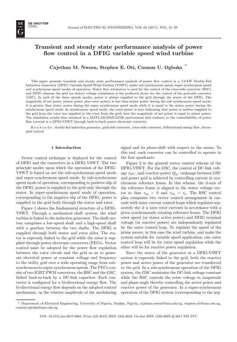
Figure 1 shows the fundamental structure of a DFIG-VSWT. Through a mechanical shaft system, the windturbine is linked to the induction generator. The shaft sys-tem comprises a low-speed shaft and a high-speed shaftwith a gearbox between the two shafts. The DFIG issupplied through both stator and rotor sides. The sta-tor is expressly linked to the grid while the rotor is sup-plied through power electronic converters (PECs). Vectorcontrol must be adopted for the power flow regulationbetween the rotor circuit and the grid so as to gener-ate electrical power at constant voltage and frequencyto the utility grid over a wide operating range from sub-synchronous to super-synchronous speeds. The PECs con-sist of two IGBT PWM converters, the RSC and the GSC,linked back-to-back by a DC-link capacitor. Each con-verter is configured for a bi-directional energy flow. Thebi-directional energy flow depends on the adopted controlmechanism, eg the relative amplitude of the modulating
signal and its phase-shift with respect to the mains. Tothis end, each converter can be controlled to operate inthe four quadrants.
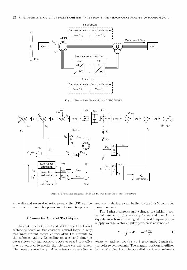
Figure 2 is the general vector control scheme of theDFIG-VSWT. For the GSC, the control of DC-link volt-age vDC , and reactive power Qgc exchange between GSCand power grid is achieved by controlling current in syn-chronous reference frame. In this scheme, the d-axis ofthe reference frame is aligned to the stator voltage vec-tor so that vqs = 0 and vds = vs . The RSC controlplan comprises two vector control arrangement in cas-cade with inner current control loops which regulates sep-arately the d–q axes rotor currents in accordance with agiven synchronously rotating reference frame. The DFIGrotor speed (or stator active power) and DFIG terminalvoltage (or reactive power) are independently regulatedby the outer control loop. To regulate the speed of theprime mover, in this case the wind turbine, and make thesystem suitable for variable speed application, one outercontrol loop will be for rotor speed regulation while theother will be for reactive power regulation.
Since the stator of the generator in a DFIG-VSWTsystem is expressly linked to the grid, both the reactivepower and active power of the generator are transferredto the grid. In a sub-synchronous operation of the DFIGsystem, the GSC maintains the DC-link voltage constantwhile the RSC controls the rotor voltage in magnitudeand phase angle thereby controlling the active power andreactive power of the generator. In a super-synchronousoperation of the DFIG system (corresponding to the neg-
∗ Department of Electrical Engineering, University of Nigeria, Nsukka, Nigeria, [email protected], [email protected],[email protected]
DOI: 10.1515/jee-2017-0004, Print (till 2015) ISSN 1335-3632, On-line ISSN 1339-309X c© 2017 FEI STU
32 C. M. Nwosu, S. E. Oti, C. U. Ogbuka: TRANSIENT AND STEADY STATE PERFORMANCE ANALYSIS OF POWER FLOW . . .
Grid
WRIG
Stator circuit
Rotor circuit
Rotor
Power electronic converter
AC
ACDC
DC
RSC GSC
PmecPgrid » Pstator + Protor
ngen
Gear
Protor < 0 Protor > 0
Sub -synchronous Over -synchronous
Pstator > 0 Pstator > 0
Sub -synchronous Over -synchronous
Fig. 1. Power Flow Principle in a DFIG-VSWT
Qf*S PI S PI S PWM PWM S PI S PI S
abc
to
dqRf
RSC
Qs*
wr*
wr
Idqr*
Vdqr
comp
Vdr
GSC
Vdqs
VDCwLfIdqf *
VDC
VDC
+
Qf
Qv -Qr
Idqr
Idqr Iabcr
Idqf
PLLSQv -Qr
Qr
-
abc
to
dq
Grid
Rotor speed
estimation
Stator flux
estimation
Qs
calculation
Idqs
ldqs
Vdqs
Vabcs
IdqrQv
Vabcs
Iabcs
lqs
lds
abc
to
dq
abc
to
dqQe Qf
calculation
Qe
Idqf
Vabc
Iabcs
Qs Lf
Fig. 2. Schematic diagram of the DFIG wind turbine control structure
ative slip and reversal of rotor power), the GSC can beset to control the active power and the reactive power.
2 Converter Control Techniques
The control of both GSC and RSC in the DFIG windturbine is based on two cascaded control loops: a veryfast inner current controller regulating the currents tothe reference values. Depending on a control aim, theouter slower voltage, reactive power or speed controllermay be adopted to specify the reference current values.The current controller provides reference signals in the
d–q axes, which are sent further to the PWM-controlledpower converter.
The 3-phase currents and voltages are initially con-verted into an α , β stationary frame, and then into adq reference frame rotating at the grid frequency. Thesupply voltage vector angular position is obtained as
θe =
∫
ωedt = tan−1 vβvα
(1)
where vα and vβ are the α , β (stationary 2-axis) sta-tor voltage components. The angular position is utilizedin transforming from the so called stationary reference
Journal of ELECTRICAL ENGINEERING 68 (2017), NO1 33
PI+ ( id - id )*
id*
id
vd
-
PI+ ( iq - iq )*
iq*
iq
vq
-
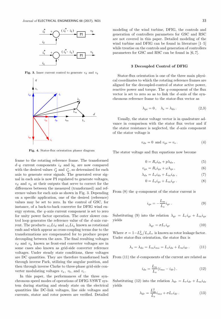
Fig. 3. Inner current control to generate vd and vq
l r
vs
iqr
iqs
is
ir
imsidrids
q
dlm
ls
Fig. 4. Stator-flux orientation phasor diagram
frame to the rotating reference frame. The transformedd–q current components id and iq, are now comparedwith the desired values i∗d and i∗q , so determined for each
axis to generate error signals. The generated error sig-nal in each axis is now PI regulated to generate voltages,vd and vq at their outputs that serve to correct for thedifferences between the measured (transformed) and ref-erence values for each axis as shown in Fig. 3. Dependingon a specific application, one of the desired (reference)values may be set to zero. In the control of GSC, forinstance, of a back-to-back converter for DFIG wind en-ergy system, the q -axis current component is set to zerofor unity power factor operation. The outer slower con-trol loop generates the reference value of the d-axis cur-rent. The products ωeLid and ωeLiq known as rotationalemfs and which appear as cross-coupling terms due to thetransformations are compensated for to produce properdecoupling between the axes. The final resulting voltagesvd and vq known as front-end converter voltages are insome cases also known as grid-side converter referencevoltages. Under steady state conditions, these voltagesare DC quantities. They are therefore transformed backthrough inverse Park, utilizing the angular position, andthen through inverse Clarke to three-phase grid-side con-verter modulating voltages va , vb , and vc .
In this paper, the performances of the three syn-chronous speed modes of operations of DFIG-VSWT sys-tem during starting and steady state on the electricalquantities like DC-link voltages, line side voltages andcurrents, stator and rotor powers are verified. Detailed
modeling of the wind turbine, DFIG, the controls andgeneration of controllers parameters for GSC and RSCare not covered in this paper. Detailed modeling of thewind turbine and DFIG can be found in literature [1–5]while treatise on the controls and generation of controllersparameters for GSC and RSC can be found in [6, 7].
3 Decoupled Control of DFIG
Stator-flux orientation is one of the three main physi-cal coordinates to which the rotating reference frames arealigned for the decoupled-control of stator active power,reactive power and torque. The q -component of the fluxvector is set to zero so as to link the d-axis of the syn-chronous reference frame to the stator-flux vector as
λqs = 0 , λs = λds . (2,3)
Usually, the stator voltage vector is in quadrature ad-vance in comparison with the stator flux vector and ifthe stator resistance is neglected, the d-axis componentof the stator voltage is
vds = 0 and vqs = vs . (4)
The stator voltage and flux equations now become
0 = Rsids + pλds , (5)
vqs = Rsiqs + ωλqs , (6)
λds = Lsids + Lmidr , (7)
0 = Lsiqs + Lmiqr . (8)
From (8) the q -component of the stator current is
iqs = −Lm
Ls
iqr . (9)
Substituting (9) into the relation λqr = Lriqr + Lmiqsyields
λqr = σLriqr (10)
Where σ = 1−L2m
/
LsLr is known as rotor leakage factor.Under stator-flux orientation, the stator flux is
λs = λds = Lmims = Lsids + Lmidr . (11)
From (11) the d-components of the current are related as
ids =Lm
Ls
(ims − idr) . (12)
Substituting (12) into the relation λdr = Lridr + Lmidsyields
λdr =L2m
Ls
ims + σLridr . (13)
34 C. M. Nwosu, S. E. Oti, C. U. Ogbuka: TRANSIENT AND STEADY STATE PERFORMANCE ANALYSIS OF POWER FLOW . . .
Representing the slip-speed (ω−ωr) in stator-flux orien-tation as ωsl , the model of the d–q rotor voltages are
vdr = Rridr + σLrpidr − ωslσLriqr , (14)
vqr =Rriqr+σLrpiqr+ωslσLridr+ωsl
L2m
Ls
ims . (15)
The stator-flux orientation sets the Ps , Qs and Te equa-tions as
Ps =3
2vqsiqs, (16)
Qs =3
2vqsids, (17)
Te =3
2
P
2λdsiqs . (18)
Here, iqs which controls the Ps , and Te is related to theiqr as
iqs = −Lm
Ls
iqr . (19)
The injection of iqr will result in proportionate changein the iqs to control the Ps , and Te .
The reactive power control current ids , is related toidr as
ims = kids + idr . (20)
where k = Ls/Lm . The injection of idr will naturallylead to smaller value of ids being drawn from the statorterminals and therefore improves the stator power factor.The process of this control is explained in Fig. 4.
For the control of the RSC and DFIG the stator fluxorientation is adopted while the grid (or stator) voltageorientation is the preferred choice for the control of theGSC.
Selection of Control Bandwidths
It is recommended that the angular switching fre-quency ωsw of the converter switches should at least befive times the closed-loop bandwidth ω0 [8] for stable op-eration of the system
ωsw ≥ 5ω0 . (21)
Using this formula and the relation tr = ln 9/ω0 , theswitching frequency (in hertz) can be related to the risetime
fsw ≥5 ln 9
2πtr≈
1.75
tr. (22)
An odd frequency modulation ratio of 39 is chosen forthe GSC. This sets the switching frequency and the ap-proximate angular switching frequency to 1950 Hz and12252 rad/s respectively. The closed-loop bandwidth maythen be calculated as
ω0 ≤ωsw
5≤
12252
5≤ 2450 rad/s. (23)
Closed-loop bandwidth of 2250 rad/s is chosen for all theGSC and RSC inner-current control loops, while closed-loop bandwidth one tenth of the inner-current value or
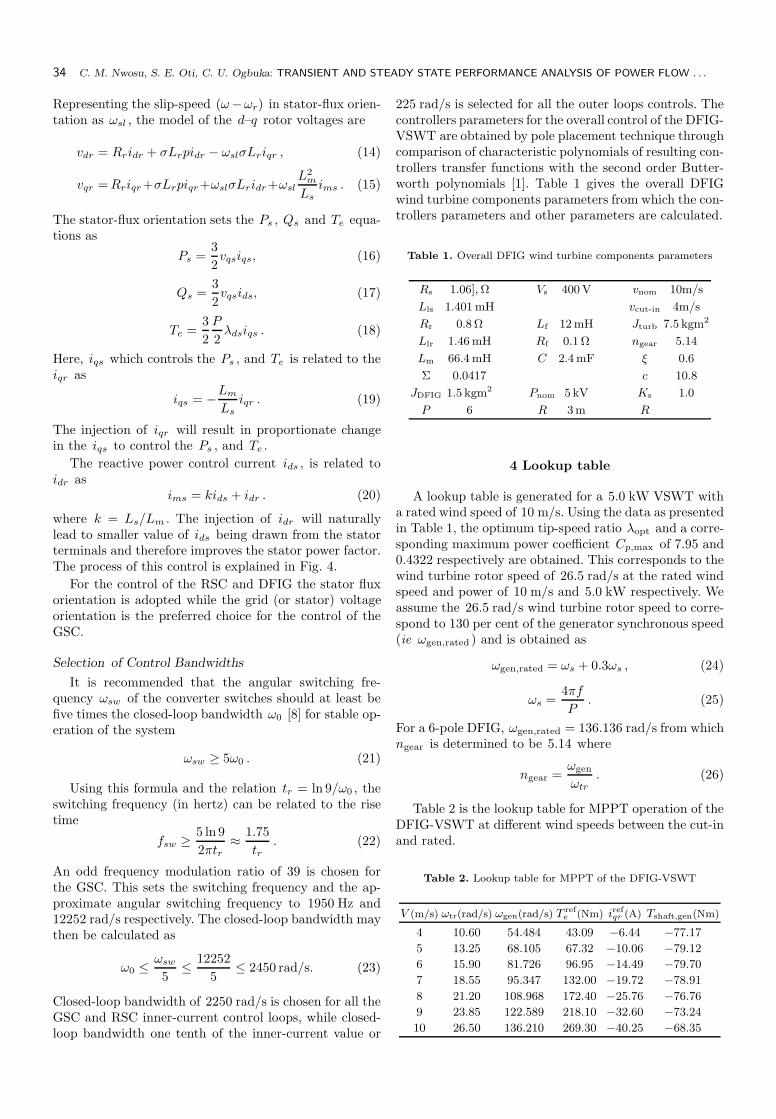
225 rad/s is selected for all the outer loops controls. Thecontrollers parameters for the overall control of the DFIG-VSWT are obtained by pole placement technique throughcomparison of characteristic polynomials of resulting con-trollers transfer functions with the second order Butter-worth polynomials [1]. Table 1 gives the overall DFIGwind turbine components parameters from which the con-trollers parameters and other parameters are calculated.
Table 1. Overall DFIG wind turbine components parameters
Rs 1.06],Ω Vs 400V vnom 10m/s
Lls 1.401mH vcut-in 4m/s
Rr 0.8Ω Lf 12mH Jturb 7.5 kgm2
Llr 1.46mH Rf 0.1Ω ngear 5.14
Lm 66.4mH C 2.4mF ξ 0.6
Σ 0.0417 c 10.8
JDFIG 1.5 kgm2 Pnom 5 kV Ks 1.0
P 6 R 3m R
4 Lookup table
A lookup table is generated for a 5.0 kW VSWT witha rated wind speed of 10 m/s. Using the data as presentedin Table 1, the optimum tip-speed ratio λopt and a corre-sponding maximum power coefficient Cp,max of 7.95 and0.4322 respectively are obtained. This corresponds to thewind turbine rotor speed of 26.5 rad/s at the rated windspeed and power of 10 m/s and 5.0 kW respectively. Weassume the 26.5 rad/s wind turbine rotor speed to corre-spond to 130 per cent of the generator synchronous speed(ie ωgen,rated ) and is obtained as
ωgen,rated = ωs + 0.3ωs , (24)
ωs =4πf
P. (25)
For a 6-pole DFIG, ωgen,rated = 136.136 rad/s from whichngear is determined to be 5.14 where
ngear =ωgen
ωtr
. (26)
Table 2 is the lookup table for MPPT operation of theDFIG-VSWT at different wind speeds between the cut-inand rated.
Table 2. Lookup table for MPPT of the DFIG-VSWT
V (m/s) ωtr(rad/s) ωgen(rad/s) Trefe (Nm) irefqr (A) Tshaft,gen(Nm)
4 10.60 54.484 43.09 −6.44 −77.17
5 13.25 68.105 67.32 −10.06 −79.12
6 15.90 81.726 96.95 −14.49 −79.70
7 18.55 95.347 132.00 −19.72 −78.91
8 21.20 108.968 172.40 −25.76 −76.76
9 23.85 122.589 218.10 −32.60 −73.24
10 26.50 136.210 269.30 −40.25 −68.35

Journal of ELECTRICAL ENGINEERING 68 (2017), NO1 35
-1.5
0.0
1.5
Stator- voltag angle (V)
0 0.02 0.06 0.08 0.10Time (s)
0.04
Fig. 5. Stator voltage vector position
-1.5
0.0
1.5
Stator- flux angle (rad/s)
2.40 2.42 2.46 2.48 2.50Time (s)
2.44
Fig. 6. Stator flux vector position
2.00 2.02 2.06 2.08 2.10Time (s)
2.04
-2
0
2
a, b flux linkages (Vs)4
-4
Fig. 7. The α–β stator flux linkages
2.00 2.02 2.06 2.08 2.10Time (s)
2.04
-2
0
2
d - axis stator flux (Vs)
4
-4
Fig. 8. The d -component of the stator flux linkage
0.5 1.5 2.0 2.5Time (s)
1.0
200
DC-link voltage (V)
800
0
600
400
Fig. 9. DC-link voltage
1.40 1.44 1.52 1.56 1.60Time (s)
1.48
0
Supply voltage and current waveforms
600
-600
Fig. 10. The steady state supply side voltage and current wave-forms
0.5 1.5 2.0 2.5Time (s)
1.00
Pr
-300
300
0
Stator, rotor, net power (kW)
Ps
Pr + Ps
Fig. 11. The α–β stator flux linkages
0.5 1.5 2.0 2.5Time (s)
1.0
200
DC-link voltage (V)
800
0
600
400
Fig. 12. The stator, rotor and net powers

36 C. M. Nwosu, S. E. Oti, C. U. Ogbuka: TRANSIENT AND STEADY STATE PERFORMANCE ANALYSIS OF POWER FLOW . . .
For a damping ratio ξ = 0.6 and rotor inertia =7.5 kgm2 , damping coefficient c and low-speed shaft stiff-ness Ks of 10.8 and 1.0 respectively are obtained. Theshaft torque at the generator input at different rotorspeed may be obtained from
Tshaft,gen =1
ngear
[
10.8(ωr−26.5)+
∫
(ωr−26.5)dt]
. (27)
5 Simulation results
Figure 5 is the stator voltage vector position whileFig. 6 is the stator flux vector position. The α–β sta-tor flux linkages are displayed in Fig. 7 while the d-component of the stator flux linkage is shown in Fig. 8.These preliminary generated waveforms and others notdisplayed here are necessary for the investigation of thesub-synchronous, super-synchronous and synchronous op-erating modes of the DFIG wind turbine system.
3.1 Sub-synchronous speed mode
In the three operating modes, the requirements arethat the GSC modulation index m1 be kept constant at0.75 while the RSC modulation index is varied in rela-tion to the operating speeds (slips) of the DFIG at dif-ferent operating modes. For the sub-synchronous speedmode, a rotor speed ωr , corresponding to ωs − 0.3ωs or73.304 rad/s is chosen. The corresponding operating slipof 0.3 is obtained. From the look-up table, these operat-ing speed and slip correspond to wind speed of between5 m/s and 6 m/s. The rotor speed is scaled down throughthe wind turbine gearbox ratio to 14.261 rad/s and thenused in (27) to generate the generator shaft torque of−79.46 Nm. For the 400 V DFIG stator voltage, the ro-tor slip voltage and the RSC modulation depth are es-tablished as 120 V and 0.39 respectively. Figure 9 is theDC-link voltage regulated to 550 V. Displayed in Fig. 10,are the steady state supply side voltage and current wave-forms showing a near unity displacement factor betweenthe waveforms. To achieve the near unity displacementfactor, the i∗qs is set to zero. The stator, rotor and net
powers are displayed in Fig. 11. The net power is the sum
of the stator and rotor powers. The stator power is nega-
tive indicating that power is supplied to the grid through
the stator of the DFIG. The rotor power is positive indi-
cating that power is supplied to the rotor from the grid
through the back-to-back converters. The net power is
also negative indicating that more power is supplied to
the grid than is taken from the grid. The magnitude of
the net power is however less than the magnitude of the
stator power.
3.2 Super-synchronous speed mode
For the super-synchronous speed mode, a rotor speed
ωr , corresponding to ωs +0.3ωs or 136.136 rad/s is cho-
sen. The corresponding operating slip of −0.3 is obtained.
From the look-up table, these operating speed and slip
correspond to the rated wind speed of 10 m/s. The rotor
speed is scaled down through the turbine gearbox ratio to
26.5 rad/s and then used in (27) to generate the generator
shaft torque of −68.31 Nm. For the 400 V DFIG stator
voltage, the rotor slip voltage and the RSC modulation
depth are established as −120 V and 0.39 respectively.
Shown in Fig. 12, is the DC-link voltage also regulated
to 550 V. Displayed in Fig. 13 are the steady state sup-
ply side voltage and current waveforms. In this mode, the
phase displacement between the phase voltage and cur-
rent is near 180 . The GSC which under sub-synchronous
speed mode functions as a rectifier now operates as an in-
verter while the RSC now operates as a rectifier. Like in
the sub-synchronous speed mode, GSC i∗qs is also set to
zero.
The stator, rotor and net powers are displayed in
Fig. 14. Like in the sub-synchronous speed mode, the sta-
tor power is negative indicating that power is supplied
to the grid through the stator of the DFIG. The rotor
power is in this mode negative indicating that power is
also supplied to the grid form the DFIG rotor through the
back-to-back converters. The net power is more negative
than the stator power. The magnitude of the net power is
therefore more than the magnitude of the stator power.
1.40 1.44 1.52 1.56 1.60Time (s)
1.48
0
Supply voltage and current waveforms
600
-600
Fig. 13. The steady state supply side voltage and current wave-forms
0.5 1.5 2.0 2.5Time (s)
1.00
Pr
Ps
Pr + Ps
-20
Stator, rotor, net power (kW)
0
20
10
-10
Fig. 14. The stator, rotor and net powers
Journal of ELECTRICAL ENGINEERING 68 (2017), NO1 37
0.5 1.5 2.0 2.5Time (s)
1.0
200
DC-link voltage (V)
800
0
600
400
Fig. 15. DC-link voltage
1.40 1.44 1.52 1.56 1.60Time (s)
1.48
0
Supply voltage and current waveforms
600
-600
Fig. 16. The steady state supply side voltage and current wave-forms
0.5 1.5 2.0 2.5Time (s)
1.00
Pr
Ps
Pr + Ps
-20
Stator, rotor, net powers (kW)
0
20
10
-10
30
Fig. 17. The stator, rotor and net powers
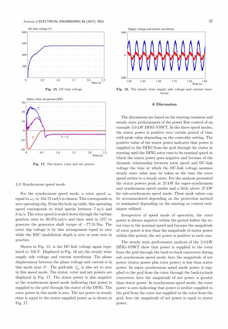
3.3 Synchronous speed mode
For the synchronous speed mode, a rotor speed ωr
equal to ωs or 104.72 rad/s is chosen. This corresponds to
zero operating slip. From the look-up table, this operating
speed corresponds to wind speeds between 7 m/s and
8 m/s. The rotor speed is scaled down through the turbine
gearbox ratio to 20.374 rad/s and then used in (27) to
generate the generator shaft torque of −77.55 Nm. The
rotor slip voltage is by this arrangement equal to zero
while the RSC modulation depth is zero or near zero in
practice.
Shown in Fig. 15, is the DC-link voltage again regu-
lated to 550 V. Displayed in Fig. 16 are the steady state
supply side voltage and current waveforms. The phase
displacement between the phase voltage and current is in
this mode near 0 . The grid-side i∗qs is also set to zero
in this speed mode. The stator, rotor and net powers are
displayed in Fig. 17. The stator power is also negative
in the synchronous speed mode indicating that power is
supplied to the grid through the stator of the DFIG. The
rotor power in this mode is zero. The net power in steady
state is equal to the stator supplied power as is shown in
Fig. 17.
6 Discussion
The discussions are based on the starting transient and
steady state performances of the power flow control of an
example 5.0 kW DFIG-VSWT. In the three speed modes,
the stator power is positive over certain period of time
with peak value depending on the controller setting. The
positive value of the stator power indicates that power is
supplied to the DFIG from the grid through the stator at
starting until the DFIG rotor runs to its nominal speed at
which the stator power goes negative and because of the
dynamic relationship between rotor speed and DC-link
voltage the time at which the DC-link voltage assumes
steady state value may be taken as the time the rotor
speed settles to a steady state. For the analysis presented
the stator powers peak at 25 kW for super-synchronous
and synchronous speed modes and a little above 27 kW
for sub-synchronous speed mode. These peak values can
be accommodated depending on the protection method
or minimized depending on the starting or control tech-
niques utilized.
Irrespective of speed mode of operation, the rotor
power is always negative within the period before the ro-
tor runs to the nominal speed and because the magnitude
of rotor power is less than the magnitude of stator power
within this period, the net power is positive in each case.
The steady state performance analysis of the 5.0 kW
DFIG-VSWT show that power is supplied to the rotor
from the grid through the back-to-back converters during
sub synchronous speed mode; here the magnitude of net
power (stator power plus rotor power) is less than stator
power. In super synchronous speed mode power is sup-
plied to the grid from the rotor through the back-to-back
converters; here the magnitude of net power is greater
than stator power. In synchronous speed mode, the rotor
power is zero indicating that power is neither supplied to
the grid from the rotor nor supplied to the rotor from the
grid; here the magnitude of net power is equal to stator
power.

38 C. M. Nwosu, S. E. Oti, C. U. Ogbuka: TRANSIENT AND STEADY STATE PERFORMANCE ANALYSIS OF POWER FLOW . . .
7 Conclusions
Steady state performance analysis of power flow con-trol in a 5.0 kW DFIG-VSWT under sub synchronousspeed, super synchronous speed and synchronous speedmodes of operation is presented.
The stator voltage and stator flux vector positions aswell as the α–β stator flux linkages, the d-componentof the stator flux linkage and other waveforms not dis-played are first generated for the investigation of the sub-synchronous, super-synchronous and synchronous speedsof operation corresponding to rotor speed ωr , of (ωs −
0.3ωs ), (ωs + 0.3ωs ) and (ωs ) respectively.
The GSC modulation index is kept constant at 0.75 inthe three operating modes and hence the DC-link voltageis maintained constant at 550 V while the RSC modula-tion index is varied in relation to the operating speeds(slips) of the DFIG at each of the operating modes.
In sub synchronous speed mode, power is supplied tothe rotor from the grid through the back-to-back convert-ers; here the magnitude of net power is less than statorpower. In super synchronous speed mode power is sup-plied to the grid from the rotor through the back-to-backconverters; here the magnitude of net power is greaterthan stator power. In synchronous mode, the rotor poweris zero indicating that power is neither supplied to thegrid from the rotor nor supplied to the rotor from thegrid; here the magnitude of net power is equal to statorpower.
It is observed that the reactive power of the generatorin each of the three speed modes is always transferred tothe grid. In the sub-synchronous speed mode the controlof the reactive power is excised on the RSC while in thesuper-synchronous operation speed mode the control ofthe reactive power is excised on the GSC.
The simulation results of the steady state performanceanalysis support the unique power flow reversal control-lability of DFIG-VSWT with the help of back-to-backpower electronic converter. The results of the analysiswill serve as a first hand base and guide for wind turbinedesign and operation engineers.
References
[1] H. M. Hasanien and E. A. Al-ammar, ”Dynamic Response Im-provement of Doubly Fed Induction GeneratorBased Wind Farmusing Fuzzy Logic Controller”, Journal of Electrical Engineering,
vol. 63, no. 5, 2012, 281–288.
[2] B. Pokharel, Modeling, Control and Analysis of a Doubly Fed
Induction Generator Based Wind Turbine System with Voltage
Regulation, MSc Thesis, Tennessee Technical University, 2011.
[3] L. Hannefors and H. P. Nee, ”Model-Based Current Control ofAC Machines using the Internal Model Control Method”, IEEETrans. Ind. Applicat., vol. 34, no. 1, 1998, 133–141.
[4] R. Pena, J. C. Clare and G. M. Asher, ”Doubly Fed Induc-tion Generator using Back-to-Back PWM Converters and itsApplication to Variable-Speed Wind-Energy Generation”, IEE
Proc.-Electr. Power Appl., vol. 143, no. 3, 1996, 231–234.
[5] O. Kamel, O. Mohand, R. Toufik and N. Taib, ”Nonlinear Pre-dictive Control of Wind Energy Conversion System using DFIG
with Aerodynamic Torque Observer”, Journal of Electrical En-gineering, vol. 65, no. 6, 2014, 333–341.
[6] C. A. Nwosu, Back-to-Back Power Electronic Converter Control
for Active Damping, Germany, LAP Lambert Academic Pub-lishing, 2012, 71–102.
[7] C. A. Nwosu and C. U. Ogbuka, ”Analysis and Verification ofthe Effects of Active Damping on the Dynamic Performance ofa Grid-Side Converter ”, Elektrika, vol. 13, 2013, 12–20.
[8] N. Rumzi, N. Idris and H. M. Yatim, ”An Improved Stator FluxEstimation in Steady-State Operation for Direct Torque Controlof Induction Machines ”, IEEE Trans. Ind. Applicat., vol. 38,2012, 110–116.
Received 20 June 2016
Cajethan Nwosu (Engr, Dr) was born 1st October 1967.He obtained the BEng, MEng, and PhD Degrees in ElectricalEngineering from the University of Nigeria, Nsukka in 1994,2004, and 2015 respectively. In 2007, he undertook a threemonths pre-doctoral research on Wind/Solar Hybrid PowerSystem and Renewable Energy Resources at the Universityof Technology, Delft (TU-Delft), the Netherlands. Since 2005,he has been with the Department of Electrical Engineering,University of Nigeria, Nsukka, where he is currently a SeniorLecturer. He had written two books and had published overthirty articles both in local and international journals. He isan executive member of Nigerian Institution of Electrical andElectronic Engineers (NIEEE), Nsukka chapter. He is a mem-ber of Power Electronics Society of Institution of Electricaland Electronic Engineering (PES IEEE). He is an editorialboard member World Science Journal of Engineering Appli-cations. His areas of research interest include power electronicconverters, electrical drives and renewable energy technolo-gies.
Stephen Ejiofor Oti (Engr, Dr) was born in 1974. He ob-tained the BEng, MEng, and PhD Degrees in Electrical Engi-neering from the University of Nigeria, Nsukka in 1998, 2006,and 2014 respectively. In 2000, he was engaged as Senior Math-ematics Teacher in Special Science School, Nsukka from wherehe joined the Electrical Engineering Department, UNN as aPrincipal Technical Officer and was later in 2007 converted tothe lecturing cadre in the same department. He is a memberof Nigerian Society of Engineers (NSE) and is also a registeredmember of Council for the Regulation of Engineering in Nige-ria (COREN). His research areas include Machine modeling,Thermal modeling, Power and Energy systems modeling andSimulations.
Cosmas Ogbuka (Engr, Dr) was born in Umuna Nigeriaon 1st April, 1981. He received his BEng (First Class Honors),MEng (Distinction) and PhD in 2004, 2009 and 2014 respec-tively in the Department of Electrical Engineering Universityof Nigeria, Nsukka, where he presently works as a Lecturer I.His research interests are in Adjustable Speed Drives of Elec-trical Machines: (DC and AC Electric Machine Torque/SpeedControl with Converters and Inverters), Electric Machines andPower Electronics. He has published both locally and interna-tionally and attended conferences within and outside Nige-ria. He is a member of Nigerian Society of Engineers (NSE),Nigerian Institution of Electrical Engineers (NIEEE), Inter-national Association of Engineers (IAENG) and is registeredby the Council for the Regulation of Engineering in Nigeria(COREN). He is presently on a postdoctoral research visitat the Chair of Electrical Drives and Actuators (EAA) Uni-versitat der Bundeswehr Munchen, Germany with ProfessorDr-Ing Dieter Gerling.