Transforming Plane Triangulations by Simultaneous Diagonal ...
100
U NIVERSITY OF O TTAWA MASTERS T HESIS Transforming Plane Triangulations by Simultaneous Diagonal Flips M Tanvir K AYKOBAD A thesis submitted in partial fulfillment of the requirements for the degree of Master of Computer Science in the School of Electrical Engineering and Computer Science Faculty of Engineering University of Ottawa c M Tanvir Kaykobad, Ottawa, Canada, 2020
Transcript of Transforming Plane Triangulations by Simultaneous Diagonal ...

UNIVERSITY OF OTTAWA
MASTERS THESIS
Transforming Plane Triangulations bySimultaneous Diagonal Flips
M Tanvir KAYKOBAD
A thesis submitted in partial fulfillment of the requirementsfor the degree of Master of Computer Science
in the
School of Electrical Engineering and Computer ScienceFaculty of EngineeringUniversity of Ottawa
c©M Tanvir Kaykobad, Ottawa, Canada, 2020

ii
Declaration of AuthorshipThis thesis titled, “Transforming Plane Triangulations by Simultaneous Diagonal
Flips” and the work presented in it are my own. I confirm that:
• This work was done wholly or mainly while in candidature for a research de-gree at this University.
• Where any part of this thesis has previously been submitted for a degree orany other qualification at this University or any other institution, this has beenclearly stated.
• Where I have consulted the published work of others, this is always clearlyattributed.
• Where I have quoted from the work of others, the source is always given. Withthe exception of such quotations, this thesis is entirely my own work.
• I have acknowledged all main sources of help.
• Where the thesis is based on work done by myself jointly with others, I havemade clear exactly what was done by others and what I have contributed my-self.
Author: M Tanvir KAYKOBAD
iii
UNIVERSITY OF OTTAWA
AbstractFaculty of Engineering
School of Electrical Engineering and Computer Science
Master of Computer Science
Transforming Plane Triangulations by Simultaneous Diagonal Flips
by M Tanvir KAYKOBAD
We explore the problem of transforming plane triangulations using simultaneousdiagonal flips. Wagner showed that any n-vertex plane triangulation can be trans-formed to any other plane triangulation on equal number of vertices using a finitesequence of diagonal flips. Later on it has been established thatO(n) individual flipssuffice to complete this transformation. Bose et al. showed that the transformationcan also be done in 4× ( 2
log 5453+ 2
log 65) logn + 2 ≈ 327.1 log n simultaneous flips. This
bound is asymptotically tight.We present two algorithms to improve the leading coefficient of this bound for
transforming any plane triangulation into any other. The first of the two algorithmslowers this bound down to 4× ( 2
log 1211+ 2
log 97) logn + 2 ≈ 85.8 log n. By processing
and preprocessing the interior and exterior of the triangulation’s Hamiltonian cycleparallelly in an interlaced fashion, we make further improvement of the algorithmfrom ≈ 327.1 log n down to 12
log 65
logn + 2 ≈ 45.6 log n.
iv
AcknowledgementsThis gives me immense pleasure to acknowledge the inspiring guidance of Dr. Jean-Lou De Carufel. He has dedicated an enormous amount of time in familiarizingme with the field of computational geometry. Our interactions have given me anappreciation towards the deep insights required in postulating, and the rigorousnessrequired in proving the said postulates in this field. I thank Dr. Anil Maheshwariand Dr. Vida Dujmovic for carefully examining my thesis, and Dr. Paola Flocchinifor chairing my thesis defence.
I would like to thank my father Dr. Mohammad Kaykobad who has alwaysbeen a passionate follower of my works, living in the diametrically opposite part ofthe globe. He has been a constant source of inspiration whenever I needed it. Mymother, Saleha Sultana Kaykobad, who has always been a great hand of support forme, accepted my isolation from her for many years only for me to have a rewardingand fruitful life. I thank my only brother Kayes Kaykobad, his wife Tanzina Khan,and my only beloved nephew Ervin Kaykobad for accepting my inability of spend-ing adequate time with them and for the understanding and support they providedfor me.
v
Contents
Declaration of Authorship ii
Abstract iii
Acknowledgements iv
1 Introduction 11.1 Triangulations, Flips and Simultaneous Flips . . . . . . . . . . . . . . . 11.2 Literature Review . . . . . . . . . . . . . . . . . . . . . . . . . . . . . . . 11.3 Summary of Known Bounds on Flips . . . . . . . . . . . . . . . . . . . . 31.4 Scope and Objectives of the Thesis . . . . . . . . . . . . . . . . . . . . . 31.5 Highlighted Results of the Thesis . . . . . . . . . . . . . . . . . . . . . . 41.6 Organization of the Thesis . . . . . . . . . . . . . . . . . . . . . . . . . . 5
2 Existing Results 62.1 Preliminaries . . . . . . . . . . . . . . . . . . . . . . . . . . . . . . . . . . 62.2 Bounds Related to Sequence of Flips . . . . . . . . . . . . . . . . . . . . 10
2.2.1 Wagner’s Results . . . . . . . . . . . . . . . . . . . . . . . . . . . 112.2.2 Mori et al.’s Bound . . . . . . . . . . . . . . . . . . . . . . . . . . 122.2.3 Other Bounds . . . . . . . . . . . . . . . . . . . . . . . . . . . . . 15
2.3 Simultaneous Flips Preliminaries . . . . . . . . . . . . . . . . . . . . . . 162.4 Transforming Triangulations in O(log n) Simultaneous Flips . . . . . . 20
2.4.1 Necessity of Ω(log n) Simultaneous Flips . . . . . . . . . . . . . 202.4.2 Related Definitions . . . . . . . . . . . . . . . . . . . . . . . . . . 212.4.3 Related Lemmas . . . . . . . . . . . . . . . . . . . . . . . . . . . 222.4.4 Overview of the Algorithm . . . . . . . . . . . . . . . . . . . . . 262.4.5 G1 → GH: Transforming Into Hamiltonian Triangulation . . . . 272.4.6 GH → Gδ: Introducing the First Dominant Vertex . . . . . . . . 302.4.7 Gδ → ∆n: Introducing the Second Dominant Vertex . . . . . . . 302.4.8 ∆n → G2: Do the Reverse to Transform ∆n to Target Triangu-
lation . . . . . . . . . . . . . . . . . . . . . . . . . . . . . . . . . . 302.4.9 Transforming Any Maximal Outerplane Graph to Any Other
of Equal Order . . . . . . . . . . . . . . . . . . . . . . . . . . . . 312.4.10 Transforming Any Triangulation to Any Other of Equal Order . 31
3 A Modification to Bose et al.’s Algorithm 323.1 Improvement of Constants c1 and c2 . . . . . . . . . . . . . . . . . . . . 323.2 Optimal Degree Restriction for Independent Set to Introduce a Domi-
nant Vertex in a Maximal Outerplane Graph . . . . . . . . . . . . . . . 40
4 Interlaced Algorithm 434.1 An Overview of the Algorithm . . . . . . . . . . . . . . . . . . . . . . . 434.2 GH → G′H: Transformation to Logarithmic Diameter . . . . . . . . . . . 44
vi
4.2.1 Overview of the Process . . . . . . . . . . . . . . . . . . . . . . . 444.2.2 Definition . . . . . . . . . . . . . . . . . . . . . . . . . . . . . . . 46
4.3 Creating Ears in Giear . . . . . . . . . . . . . . . . . . . . . . . . . . . . . 48
4.3.1 Properties of Preparation Method . . . . . . . . . . . . . . . . . 494.3.2 Identifying the Earing Vertex Set Ii
ear . . . . . . . . . . . . . . . . 504.3.3 Identifying Ii
avoid by Partially Computing Siear . . . . . . . . . . . 52
Steps for Partially Computing Iiavoid . . . . . . . . . . . . . . . . 53
Steps for Completing The Computation of Iiavoid . . . . . . . . . 54
4.3.4 Computing Siprep Using the Preparation Method . . . . . . . . . 55
4.3.5 Completing the Computation of Siear—Obtaining Si . . . . . . . 56
Steps for Completing The Computation of Siear . . . . . . . . . . 58
4.3.6 Flippability of Si . . . . . . . . . . . . . . . . . . . . . . . . . . . 594.3.7 Initiating the 1st Iteration . . . . . . . . . . . . . . . . . . . . . . 62
4.4 The Preparation Method . . . . . . . . . . . . . . . . . . . . . . . . . . . 634.4.1 Properties of Preparation Method . . . . . . . . . . . . . . . . . 634.4.2 Preliminaries . . . . . . . . . . . . . . . . . . . . . . . . . . . . . 634.4.3 Requiring Avoiding Vertices to Have at Least One Internal Chord 644.4.4 Maximal Outerplane Graph Partitioning Algorithm . . . . . . . 644.4.5 Colouring of the Vertices and the Overall Goal . . . . . . . . . . 664.4.6 Procedure GENERATESUBGRAPHS(G, Iavoid) Generates Partitioned
Subgraphs . . . . . . . . . . . . . . . . . . . . . . . . . . . . . . . 664.4.7 Flipping All Provisioning Chords of a Partitioned Subgraph . . 714.4.8 Categorization of the Red Vertices . . . . . . . . . . . . . . . . . 74
Case 1: Non-priority BRB vertex . . . . . . . . . . . . . . . . . . 77Case 2: Non-priority BRG vertex . . . . . . . . . . . . . . . . . . 77Case 3: Non-priority GRG vertex . . . . . . . . . . . . . . . . . . 77Case 4: Priority BRB vertex . . . . . . . . . . . . . . . . . . . . . 77Case 5: Priority BRG vertex . . . . . . . . . . . . . . . . . . . . . 78Case 6: Priority GRG vertex . . . . . . . . . . . . . . . . . . . . . 78
4.4.9 Provisioning Chord Sufficiency . . . . . . . . . . . . . . . . . . . 784.5 G′H → ∆n: Introducing Two Dominant Vertices . . . . . . . . . . . . . . 824.6 Complexity Analysis for the Interlaced Algorithm . . . . . . . . . . . . 83
G1 → GH: Transforming Into Hamiltonian Triangulation . . . . 83GH → G′H: Transformation to Logarithmic Diameter . . . . . . 84G′H → ∆n: Introducing Two Dominant Vertices . . . . . . . . . . 84∆n → G2: Do the Reverse to Transform ∆n to Target Triangu-
lation . . . . . . . . . . . . . . . . . . . . . . . . . . . . 84
5 Conclusion 865.1 Open Problems . . . . . . . . . . . . . . . . . . . . . . . . . . . . . . . . 87
Bibliography 88
Alphabetical Index 90

vii
List of Figures
2.1 Example of graphs . . . . . . . . . . . . . . . . . . . . . . . . . . . . . . 72.2 Diagonal flip . . . . . . . . . . . . . . . . . . . . . . . . . . . . . . . . . . 92.3 Canonical triangulation . . . . . . . . . . . . . . . . . . . . . . . . . . . 102.4 Introducing dominant vertex via Wagner’s method . . . . . . . . . . . 112.5 Transforming Hamiltonian triangulation to ∆n via sequential flips . . . 132.6 Removing separating triangles via flips . . . . . . . . . . . . . . . . . . 142.7 Simultaneous flip . . . . . . . . . . . . . . . . . . . . . . . . . . . . . . . 162.8 Consecutivity . . . . . . . . . . . . . . . . . . . . . . . . . . . . . . . . . 172.9 Bad pair . . . . . . . . . . . . . . . . . . . . . . . . . . . . . . . . . . . . 172.10 Blocking edge . . . . . . . . . . . . . . . . . . . . . . . . . . . . . . . . . 172.11 Blocking edge is flippable . . . . . . . . . . . . . . . . . . . . . . . . . . 192.12 An edge’s corresponding bad edge and blocked edge are consecutive . 192.13 Necessity of Ω(log n) simultaneous flips . . . . . . . . . . . . . . . . . . 202.14 Dual tree of maximal outerplane graph . . . . . . . . . . . . . . . . . . 222.15 Introducing a dominant vertex . . . . . . . . . . . . . . . . . . . . . . . 242.16 Requirement for Hamiltonian triangulation via simultaneous flip . . . 282.17 Transforming into Hamiltonian Triangulation . . . . . . . . . . . . . . . 29
3.1 No two consecutive chords can both be blocked . . . . . . . . . . . . . 333.2 No three blocking chords can share a face . . . . . . . . . . . . . . . . . 343.3 Vertices of I5 must have 2 non-consecutive chords . . . . . . . . . . . . 37
4.1 Overview of the Interlaced Algorithm . . . . . . . . . . . . . . . . . . . 454.2 Avoiding vertex set Ii
avoid . . . . . . . . . . . . . . . . . . . . . . . . . . . 474.3 Example of Chord-path . . . . . . . . . . . . . . . . . . . . . . . . . . . . 474.4 Preliminaries on the order of flipping Consecutive earing chords . . . 494.5 Earing vertex’s last chord is flippable iff the vertex is not avoiding . . . 504.6 Both earing chords cannot block provisioning chords . . . . . . . . . . 534.7 Vertices of Ii
avoid have at least 1 local chord each in Giprep . . . . . . . . . 56
4.8 Neither earing chords are 2-chords . . . . . . . . . . . . . . . . . . . . . 574.9 If a blocked earing chord produces foreign 2-chord of Ci
prep, its con-secutive earing chord is flippable . . . . . . . . . . . . . . . . . . . . . . 59
4.10 Provisioning chord cannot form bad pair with earing chord . . . . . . . 614.11 Avoiding vertices must have at least 1 internal chord . . . . . . . . . . 654.12 Partitioning a maximal outerplane graph into partitioned subgraphs . 684.13 Every partitioned subgraph must contain at least one green vertex . . 704.14 Partitioned Subgraph BRB adjacency . . . . . . . . . . . . . . . . . . . . 704.15 Provisioning chords sharing a face . . . . . . . . . . . . . . . . . . . . . 724.16 GRG vertex has multiple provisioning chords or it dominates a green
vertex . . . . . . . . . . . . . . . . . . . . . . . . . . . . . . . . . . . . . . 754.17 Processing priority BRG vertices . . . . . . . . . . . . . . . . . . . . . . 784.18 Meeting singly provisioning chord requirement . . . . . . . . . . . . . 82
viii
List of Tables
1.1 Summary of bounds on flips . . . . . . . . . . . . . . . . . . . . . . . . . 3
3.1 Optimal degree for ear decomposition . . . . . . . . . . . . . . . . . . . 41
4.1 Types of red vertices in partitioned subgraphs . . . . . . . . . . . . . . 76
ix
To Mom and Dad
1
Chapter 1
Introduction
Computational geometry is a branch of computer science that studies algorithms forsolving geometrical problems arising in various fields including robotics, computergraphics, CAD/CAM and computational visualization. Other important applica-tions of computational geometry include geographic information system, integratedcircuit design, computer-aided engineering, and computer vision. Computationalgeometry deals with development of efficient data structures, and algorithms forsolving problems defined in terms of geometrical objects like points, lines, circlesand polygons. Some of the classical problems addressed in computational geome-try are closest pair, convex hull, Voronoi diagram, Delaunay triangulation of a set ofpoints in static or dynamic setting.
1.1 Triangulations, Flips and Simultaneous Flips
An edge flip is an operation that replaces an edge of a graph with a new edge, keepingthe graph in the same class as the original graph. For graphs of equal vertices andedges, the number of edge flips required to transform one into another gives a senseof similarity between the two graphs. A plane graph is a graph that is embeddedin a plane without any of its edges intersecting except at their vertices. A graph isplanar if it admits a plane embedding. A simple graph does not contain any loops orparallel edges. For the class of simple plane graphs, if an edge lies on two triangularfaces, the two faces form a quadrilateral of which that edge is a diagonal. By flippingof an edge we mean replacing this diagonal by the other diagonal of quadrilateralprovided that after the flip the graph remains plane and simple. If a set of edge flipoperations are done simultaneously with the resulting graph still staying in the sameclass, we call it a simultaneous flip. A triangulation is a simple plane graph in whichevery face is a triangle.
1.2 Literature Review
The problem of transforming one triangulation into another via diagonal flips hasbeen well addressed in the literature (see Whitney (1931), Wagner (1936), Negamiand Nakamoto (1993), Nakamoto (1996), Brunet, Nakamoto, and Negami (1996),Komuro (1997), Hurtado, Noy, and Urrutia (1999), Gao, Urrutia, and Wang (2001),Cortés et al. (2002), Mori, Nakamoto, and Ota (2003), Bose et al. (2007), Bose andHurtado (2009), Bose and Verdonschot (2011), Souvaine, Tóth, and Winslow (2011),Bose et al. (2014), Frati (2015), Lubiw and Pathak (2015), Cardinal et al. (2018)). Wag-ner (1936) proved that any two triangulations can be transformed into each other,
Chapter 1. Introduction 2
up to homeomorphism, by a finite sequence of diagonal flips. Nakamoto (1996) fur-ther proved that any two bipartite quadrangulations of any closed surface are trans-formed into each other by two kinds of transformations, called the diagonal slideand the diagonal rotation, up to homeomorphism, if they have the same and suffi-ciently large number of vertices. Hurtado, Noy, and Urrutia (1999) proved that everytriangulation on n vertices has at least n−4
2 flippable edges, and this bound cannot beimproved in general. Cortés et al. (2002) proved that any two outer-triangulationson the same closed surface can be transformed into each other by a sequence of diag-onal flips, up to isotopy, if they have sufficiently large and equal number of vertices.Galtier et al. (2003) proved that triangulation of any convex polygon can be trans-formed into another using O(log n) simultaneous flips, and that this bound is tight.Bose et al. (2007) devised an O(log n) algorithm to transform any triangulation toany other triangulation on the same number of vertices by simultaneous flips.
Souvaine, Tóth, and Winslow (2011) proved that every straight-line triangulationon n vertices contains at least (n−4)
5 simultaneously flippable edges. This bound is thebest possible, and resolves an open problem posed by Galtier et al. (2003).
Diagonal flipping has received wide attention in the literature. Bose and Ver-donschot (2011) discussed interesting history of diagonal flipping in combinatorialtriangulations. Bose and Hurtado (2009) cited over 100 papers related to the topic.The first paper on the topic came out in 1936, where Wagner proved that any trian-gulation can be transformed to any other by flipping of diagonals. He also foundthat this process can be standardized by transforming through the so-called canoni-cal triangulation. Construction of canonical triangulation can be facilitated if there isa Hamiltonian cycle. Chiba and Nishizeki (1989) presented an algorithm for finding aHamiltonian cycle in linear time and storage in 4-connected planar graphs while thepreviously best algorithm given by Beauchamps (1978) uses O(n3) time and space,where n is the number of vertices in a graph.
There have been some extremal results as to the maximum and minimum num-ber of edges that can always be simultaneously flipped in an n-vertex triangulation.Bose et al. (2007) showed that at most n − 2 edges can ever be flipped simultane-ously, that every triangulation has at least (n−2)
3 edges that can be flipped simultane-ously and that there exist triangulations where at most 6(n−2)
7 edges can be flippedsimultaneously. They further proved that every combinatorial triangulation of atleast six vertices has a simultaneous flip into a 4-connected triangulation, and thatit can be computed in linear time. It follows that every triangulation has a simulta-neous flip into a Hamiltonian triangulation. This result is used to prove that for anytwo n-vertex triangulations, there exists a sequence of O(log n) simultaneous flipsto transform one into the other. The total number of edges flipped in this sequenceisO(n). They also showed that for every triangulation on n vertices there is a simul-taneous flip of less than 2n
3 edges to a 4-connected triangulation. The bound on thenumber of edges is tight, up to an additive constant.
Bose et al. (2007) found an upper bound on the number of simultaneous flips byusing similar arguments as in Mori, Nakamoto, and Ota (2003) made in their paper.
Souvaine, Tóth, and Winslow (2011) showed that every triangulation on n ≥ 6vertices can be flipped into a Hamiltonian triangulation using a sequence of less thann2 combinatorial edge flips. The previously best upper bound uses 4-connectivity as ameans to establish Hamiltonicity. But in general, about 3n
5 flips are necessary to reacha 4-connected triangulation. Their result improves the upper bound on the diameterof the flip graph of combinatorial triangulations on n vertices from 5.2n − 33.6 to5n− 23.

Chapter 1. Introduction 3
1.3 Summary of Known Bounds on Flips
In Table 1.1, we have summarized results available in the literature both in respectof individual flips and simultaneous flips, and their lower and upper bounds fortransforming combinatorial and geometric triangulations.
Some of the terms used in this table are defined in Chapter 2.
TABLE 1.1: Summary of bounds on flips
ProblemCombinatorial Geometric
lower upper lower upper
Sequential Flips Ω(n) 6n− 30 Ω(n2) O(n2)
on Triangulations Mori, Nakamoto, and Ota (2003) Hurtado, Noy, and Urrutia (1999)
Simultaneous Flips on Ω(log n) 4× ( 2log 54
53+ 2
log 65) log n + 2 Ω(n) O(n)
triangulations/general polygons Bose et al. (2007) Hurtado, Noy, and Urrutia (1999) Gao, Urrutia, and Wang (2001)
Simultaneous Flips Ω(log n) O(log n) Ω(log n) O(log n)maximal outerplane graphs Bose et al. (2007) Galtier et al. (2003)
Maximum number of n− 2 d(n−4)/2eflippable edges Gao, Urrutia, and Wang (2001) Hurtado, Noy, and Urrutia (1999)
Size of a Maximum (n−2)/3 n− 2 (n−4)/6 (n−4)/5
Flippable Edge set Bose et al. (2007) Galtier et al. (2003)
1.4 Scope and Objectives of the Thesis
In this thesis we study simple and plane triangulation—in particular, how to trans-form an n-vertex triangulation G1 into another n-vertex triangulation G2 via simul-taneous diagonal flips. The available literature is studied to identify opportunitiesfor improvement.
Properties of bad pairs, blocked edges and blocking edges will be further studied andexploited under the context of empty cycles to devise a more efficient algorithm fortransforming an arbitrary triangulation to the one with logarithmic diameter.
In fact we have devised two algorithms, the first one in Chapter 3 and the secondone in Chapter 4 that have resulted in improvement of leading coefficients of Boseet al. (2007) algorithm. The first one ensures transformation of any triangulationinto another by 85.8 log n simultaneous flips, whereas the second one does the job in45.6 log n simultaneous flips compared to 327.1 log n of Bose et al. (2007) algorithm.

Chapter 1. Introduction 4
1.5 Highlighted Results of the Thesis
This thesis has the following important results that led to the improvement of thealgorithm for transforming a triangulation into another by simultaneous flips.
Lemma 3.3. Given a triangulation G with a cycle C, no two consecutive chords of C canboth be blocked.
Lemma 3.11. Let G be a triangulation with an empty cycle C, with a set S of blockingexternal chords of C. Then at least half of the chords in S can be simultaneously flipped.
The above results lead to the following theorem that reduces the complexity oftransforming a maximum outerplane graph into one diameter of whose dual tree isO(log n).
Theorem 3.13. Let G be a maximal outerplane graph on n vertices. Then G can be trans-formed by a sequence of at most c1 log n simultaneous flips into a maximal outerplane graphX such that the diameter of its dual tree X∗ is at most c1 log n, where c1 = 2
log 97≈ 5.51.
Lemma 3.14. Let G be a triangulation and C be an empty cycle of G with n vertices. (Gmay have more than n vertices.) Then G can be transformed by a sequence of at most c2 log nsimultaneous flips into a triangulation X in which C is an empty cycle and the diameter ofthe dual tree of XC is at most c2 log n. Here c2 = 2/ log 12
11 ≈ 15.93.
The above results of Chapter 3 have been embodied to obtain a better algorithmfor transformation of a triangulation into one, for which the dual tree has O(log n)diameter using reduced number of simultaneous flips.
Theorem 3.15. Let G1 and G2 be triangulations on n vertices. There is a sequence of atmost 2 + 4(c1 + c2) log n ≈ 85.8 log n simultaneous flips to transform G1 into G2, wherec1 = 2
log 97≈ 5.52 and c2 = 2
log 1211≈ 15.93.
The next lemma gives the intuition that given a Hamiltonian triangulation, itmay be possible to make the diameter of the dual tree of its two maximal outerplanegraphs in an interlaced fashion.
Lemma 4.24. No provisioning chord can form a bad pair with any earing chord.
For a Hamiltonian triangulation, the next lemma introduces a method to prepro-cess the other maximal outerplane graph while creating ears in one.
Lemma 4.45. Given a maximal outerplane graph G and a set on non-consecutive ver-tices Iavoid on its maximal cycle C, an ordered set of two simultaneous flip sets Sprep :=(Sprep1 , Sprep2) can be computed, such that the graph G〈Sprep〉 satisfies the following prop-erties:
1 The simultaneous flip sets in Sprep1 and Sprep2 consist of only provisioning chords ofG and G′ := G〈Sprep1〉 respectively.
2 Every vertex in Iavoid either has at least 3 internal chords in G〈Sprep〉, or it dominatesa vertex of G〈Sprep〉 not in Iavoid.
3 No two singly provisioning chords of the same vertex of Iavoid is in Sprep1 .
The above results of Chapter 4 led to a further improvement to the algorithm fortransformation of a triangulations.
Theorem 4.48. Let G1 and G2 be two triangulations on n vertices. There is a sequence of nomore than c log n + 2 simultaneous flips to transform G1 into G2, where c = 12
log 65≈ 45.6.

Chapter 1. Introduction 5
1.6 Organization of the Thesis
In Chapter 1 we give an introduction to our problem and briefly review the availableliterature on the topic, discuss scope and objectives of the thesis and its organization.In Chapter 2 we discuss some of the important results available in the literature ondiagonal flips, provide a brief explanation, and sketch proofs of these results forready reference and completeness of the exposition.
We present two new algorithms in this thesis. The first of these algorithms is adirect modification of the algorithm introduced by Bose et al. (2007) and presentedin Chapter 3. Here we have chosen vertices of the independent set I of degree notexceeding 5 for transforming a larger fraction of vertices into ears. We have alsoexploited some properties of blocking and blocked chords to reduce loss incurred inBose et al. (2007) algorithm. In Chapter 4 we present our second algorithm whichfurther reduces the number of simultaneous flips required to transform any trian-gulation into any other with the same number of vertices. In Chapter 5 we presentconclusions and provide a list of open problems that can be pursued for future re-search in the area. The thesis ends with a bibliography and an index.
In this thesis, all logarithms used are to the base 2. So we use log n to mean log2 n.We also use abbreviation WLOG for the phrase "without loss of generality" to reducethe text size. Similarly, the phrase ’if and only if’ is abbreviated as IFF.
6
Chapter 2
Existing Results
There have been a number of works on diagonal flips in (planar) triangulation. Wag-ner showed that the process of transformation of a triangulation into another bydiagonal flips can be standardized by transforming each of them into a canonical tri-angulation. In this chapter we discuss some important results together with theirproofs. We start with some important definitions.
2.1 Preliminaries
Let us first start with some definitions.
Definition 2.1 (Graph). A graph G is an ordered pair G = (V, E), where V is a set ofvertices and E the set of edges. Each edge is a pair u, v, where u ∈ V, v ∈ V and u 6= vand is expressed by uv ∈ E.
The order of a graph is the cardinality of its vertex set and is denoted by n. Thenumber of edges incident to a vertex v in a graph G is called its degree, and is writtenas degG(v) or just deg(v) when there is no ambiguity. If two vertices of a graphare connected by an edge then they are called adjacent, and otherwise non-adjacent.Notice that according to Definition 2.1, a graph can neither have multiple edgesconnecting the same pair of vertices (called parallel edges), nor have any edge thatconnects a vertex to itself (called loop). Graphs without loops and parallel edges arecalled simple graphs. In this thesis unless specifically mentioned, all graphs aresimple, and thus fall into our definition of graph. Figures 2.1a, 2.1b, and 2.1c areexamples of graphs. Figure 2.1d is not a simple graph as it contains parallel edgesand therefore in the scope of this thesis is not considered a graph.
Definition 2.2 (Subgraph). Given two graphs G = (V, E) and G′ = (V ′, E′), if V ′ ⊆ Vand E′ ⊆ E∩ (V ′×V ′), then G′ is called a subgraph of G. And G is called the supergraphof G′.
Definition 2.3 (Induced Subgraph). Given a graph G = (V, E) and its subgraph G′ =(V ′, E′), G′ is called a vertex induced subgraph or in short an induced subgraph of G, ifthere exists a vertex set S ⊆ V such that for all edges vivj ∈ E, the vertices vi, vj ∈ S if andonly if vivj ∈ E′.
Definition 2.4 (Edge Induced Subgraph). Given a graph G = (V, E) and its subgraphG′ = (V ′, E′), if for all vertex v ∈ V, v ∈ V ′ if and only if v is incident to an edge in E′,then G′ is called an edge induced subgraph of G by E′.
Definition 2.5 (Complete Graph). A graph of order n, where every pair of vertices isconnected by an edge, is a complete graph and is represented as Kn.

Chapter 2. Existing Results 7
(a) Maximal outerplane graph with 10vertices (b) K5 is simple but not planar
(c) Despite K4 being planar, this embed-ding of K4 is not a plane graph
(d) The graph of Konigsberg bridges isnot simple and hence not a graph per
Definition 2.1
FIGURE 2.1: Example of Graphs
Definition 2.6 (Complete Bipartite Graph). A complete bipartite graph is a graphG = (V, E) where every vertex v ∈ V can be assigned to one of two sets S1 and S2, suchthat no pair of vertices in the same set are connected and every pair of vertices from differentsets are. If |S1| = m, |S2| = n, then the complete bipartite graph is referred as Km,n.
Definition 2.7 (Edge Subdivision). Given a graph G = (V, E), the edge subdivisionoperation for an edge uv ∈ E is the deletion of the edge uv and adding two edges uw andvw such that w is a new vertex in the graph. The obtained new graph after the operation isG′ := (V ′ := V ∪ w | w /∈ V, E′ := (E \ uv) ∪ uw, vw).
Definition 2.8 (Graph Subdivision). Given a graph G = (V, E), any graph is called asubdivision of G, if it can be generated by a sequence of edge subdivision operations onG.
Definition 2.9 (Planar Graph). A graph is said to be planar if it can be embedded in theplane with edges intersecting only at their endpoints.
Definition 2.10 (Plane Graph). If an embedding in the plane has been provided for a planargraph such that no two edges in the given embedding intersect except at their endpoints, thenthe embedded graph is called a plane graph.
Figure 2.1b does not correspond to a planar graph. Although K4 is planar, theembedding of K4 given in Figure 2.1c is not a plane graph. Figure 2.1a and 2.1d areexamples of plane graphs. Kuratowski (1930) proved that a graph is planar IFF itdoes not contain any subdivision of K5 or K3,3.
Definition 2.11 (Path). Given a graph G = (V, E), a path in G is a finite sequence(v0, v1, . . . , vk) of vertices such that for all 0 ≤ i ≤ k− 1, vivi+1 ∈ E and ∀i, j 0 ≤ i, j ≤k− 1 | vi = vj ⇐⇒ i = j.
Path can also be denoted by the sequence of edges (v0v1, v1v2, · · · , vk−1vk). Thelength of a path is the number of edges in it. In this case it is k. If there is a pathbetween every pair of vertices of a graph then the graph is called connected.

Chapter 2. Existing Results 8
Definition 2.12 (Cycle). Given a graph G = (V, E), a cycle or k-cycle is a sequence ofvertices (v0, v1, . . . , vk−1, v0), where (v0, v1, . . . , vk−1) form a (k− 1)-path, and vk−1v0 ∈E.
In this thesis every 3-cycle is called a triangle.
Definition 2.13 (Hamiltonian Cycle). Let G = (V, E) be a graph of order n. A Hamil-tonian cycle in G is an n-cycle.
Definition 2.14 (Chord). Given a graph G = (V, E) with a cycle C, any edge whose bothendpoints connect two non-adjacent vertices of C is called a chord of C. If G is a plane graph,a chord is called an internal chord if it passes through the interior of its cycle. Otherwise, itis called an external chord.
Definition 2.15 (k-Vertex-Connected). A graph G = (V, E) of order > k is a k-vertex-connected or in short k-connected graph if it cannot be made disconnected by deletion offewer than k vertices.
Definition 2.16 (Tree). A graph G = (V, E) is a tree if there is a unique path betweenevery pair of its vertices.
A tree of n vertices has exactly n− 1 edges and no cycles.
Definition 2.17 (Triangulation). A triangulation is a plane graph in which every face isa triangle.
Definition 2.18 (Combinatorial Embedding). An embedded planar graph uniquely de-fines cyclic order of edges incident to the same vertex. The set of all these cyclic orders iscalled a rotation system and often combinatorial embedding. Embeddings following thesame rotation system are considered to be equivalent and the corresponding equivalence classof embeddings is called combinatorial embedding.
Definition 2.19 (Region, Face). Given a plane graph G = (V, E), every cycle of G sepa-rates the plane into two distinct regions. If a region does not contain another region, then itis called a face.
Given a combinatorial embedding of a planar graph, all plane graphs corre-sponding to the combinatorial embedding are said to be in an equivalence class. Theyall have exactly one external or unbounded face, with all the remaining faces beingbounded by cycles. To be able to talk about the interior and exterior of cycles wenominate one face of the graph to be the outerface. In every figure in this thesis, theouterface is intentionally drawn as the unbounded face of the plane graphs—makingthe external face the outerface. Once the outerface has been defined, for any cycle Cin the graph we can differentiate between the two regions it separates—one as theinternal denoted by int(C) and the other the external region of the cycle denoted byext(C). Neither int(C) nor the ext(C) contains the vertices of C.
Definition 2.20 (Outerplane Graph). Given a plane graph G = (V, E), if its outerfacecontains all its vertices, then G is an outerplane graph.
Definition 2.21 (Outerplanar Graph). If a planar graph G = (V, E) can be embedded ina plane such that it would be an outerplane graph, then G is an outerplanar graph.
Chartrand and Harary (1967) proved that any graph that does not contain a sub-division of K4 or K2,3 is outerplanar. Given an outerplanar graph, its Hamiltoniancycle is called the maximal cycle. Note that the maximal cycle of an outerplane graphseparates its outerface from all the other faces.
Chapter 2. Existing Results 9
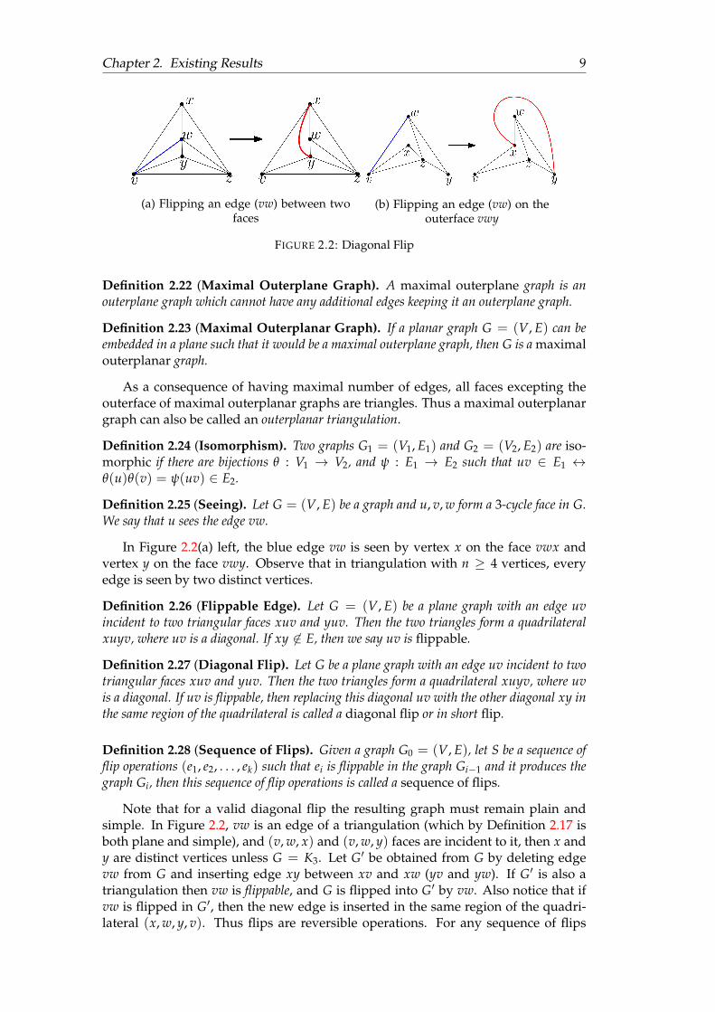
(a) Flipping an edge (vw) between twofaces
(b) Flipping an edge (vw) on theouterface vwy
FIGURE 2.2: Diagonal Flip
Definition 2.22 (Maximal Outerplane Graph). A maximal outerplane graph is anouterplane graph which cannot have any additional edges keeping it an outerplane graph.
Definition 2.23 (Maximal Outerplanar Graph). If a planar graph G = (V, E) can beembedded in a plane such that it would be a maximal outerplane graph, then G is a maximalouterplanar graph.
As a consequence of having maximal number of edges, all faces excepting theouterface of maximal outerplanar graphs are triangles. Thus a maximal outerplanargraph can also be called an outerplanar triangulation.
Definition 2.24 (Isomorphism). Two graphs G1 = (V1, E1) and G2 = (V2, E2) are iso-morphic if there are bijections θ : V1 → V2, and ψ : E1 → E2 such that uv ∈ E1 ↔θ(u)θ(v) = ψ(uv) ∈ E2.
Definition 2.25 (Seeing). Let G = (V, E) be a graph and u, v, w form a 3-cycle face in G.We say that u sees the edge vw.
In Figure 2.2(a) left, the blue edge vw is seen by vertex x on the face vwx andvertex y on the face vwy. Observe that in triangulation with n ≥ 4 vertices, everyedge is seen by two distinct vertices.
Definition 2.26 (Flippable Edge). Let G = (V, E) be a plane graph with an edge uvincident to two triangular faces xuv and yuv. Then the two triangles form a quadrilateralxuyv, where uv is a diagonal. If xy 6∈ E, then we say uv is flippable.
Definition 2.27 (Diagonal Flip). Let G be a plane graph with an edge uv incident to twotriangular faces xuv and yuv. Then the two triangles form a quadrilateral xuyv, where uvis a diagonal. If uv is flippable, then replacing this diagonal uv with the other diagonal xy inthe same region of the quadrilateral is called a diagonal flip or in short flip.
Definition 2.28 (Sequence of Flips). Given a graph G0 = (V, E), let S be a sequence offlip operations (e1, e2, . . . , ek) such that ei is flippable in the graph Gi−1 and it produces thegraph Gi, then this sequence of flip operations is called a sequence of flips.
Note that for a valid diagonal flip the resulting graph must remain plain andsimple. In Figure 2.2, vw is an edge of a triangulation (which by Definition 2.17 isboth plane and simple), and (v, w, x) and (v, w, y) faces are incident to it, then x andy are distinct vertices unless G = K3. Let G′ be obtained from G by deleting edgevw from G and inserting edge xy between xv and xw (yv and yw). If G′ is also atriangulation then vw is flippable, and G is flipped into G′ by vw. Also notice that ifvw is flipped in G′, then the new edge is inserted in the same region of the quadri-lateral (x, w, y, v). Thus flips are reversible operations. For any sequence of flips
Chapter 2. Existing Results 10
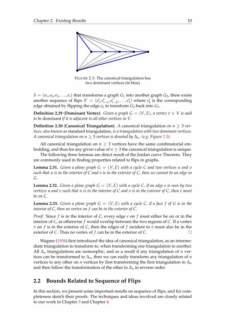
FIGURE 2.3: The canonical triangulation hastwo dominant vertices (in blue)
S = (e1, e2, e3, . . . , ei) that transforms a graph G1 into another graph G2, there existsanother sequence of flips S′ = (e′i, e′i−1, e′i−2, . . . , e′1) where e′k is the correspondingedge obtained by flipping the edge ek to transform G2 back into G1.
Definition 2.29 (Dominant Vertex). Given a graph G = (V, E), a vertex v ∈ V is saidto be dominant if it is adjacent to all other vertices in V.
Definition 2.30 (Canonical Triangulation). A canonical triangulation on n ≥ 3 ver-tices, also known as standard triangulation, is a triangulation with two dominant vertices.A canonical triangulation on n ≥ 3 vertices is denoted by ∆n. (e.g. Figure 2.3).
All canonical triangulation on n ≥ 3 vertices have the same combinatorial em-bedding, and thus for any given value of n ≥ 3 the canonical triangulation is unique.
The following three lemmas are direct result of the Jordan curve Theorem. Theyare commonly used in finding properties related to flips in graphs.
Lemma 2.31. Given a plane graph G = (V, E) with a cycle C and two vertices u and vsuch that u is in the interior of C and v is in the exterior of C, then uv cannot be an edge inG.
Lemma 2.32. Given a plane graph G = (V, E) with a cycle C, if an edge e is seen by twovertices u and v such that u is in the interior of C and v is in the exterior of C, then e mustbe on C.
Lemma 2.33. Given a plane graph G = (V, E) with a cycle C, if a face f of G is in theinterior of C, then no vertex on f can be in the exterior of C.
Proof. Since f is in the interior of C, every edge e on f must either be on or in theinterior of C, as otherwise f would overlap between the two regions of C. If a vertexv on f is in the exterior of C, then the edges of f incident to v must also be in theexterior of C. Thus no vertex of f can be in the exterior of C.
Wagner (1936) first introduced the idea of canonical triangulation, as an interme-diate triangulation to transform to, when transforming one triangulation to another.All ∆n triangulations are isomorphic, and as a result if any triangulation of n ver-tices can be transformed to ∆n, then we can easily transform any triangulation of nvertices to any other on n vertices by first transforming the first triangulation to ∆nand then follow the transformation of the other to ∆n in reverse order.
2.2 Bounds Related to Sequence of Flips
In this section, we present some important results on sequence of flips, and for com-pleteness sketch their proofs. The techniques and ideas involved are closely relatedto our work in Chapter 3 and Chapter 4.
Chapter 2. Existing Results 11
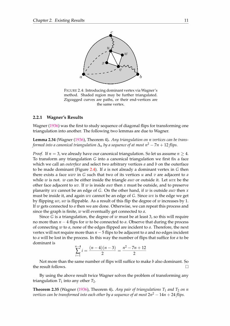
FIGURE 2.4: Introducing dominant vertex via Wagner’smethod. Shaded region may be further triangulated.Zigzagged curves are paths, or their end-vertices are
the same vertex.
2.2.1 Wagner’s Results
Wagner (1936) was the first to study sequence of diagonal flips for transforming onetriangulation into another. The following two lemmas are due to Wagner.
Lemma 2.34 (Wagner (1936), Theorem 4). Any triangulation on n vertices can be trans-formed into a canonical triangulation ∆n by a sequence of at most n2 − 7n + 12 flips.
Proof. If n = 3, we already have our canonical triangulation. So let us assume n ≥ 4.To transform any triangulation G into a canonical triangulation we first fix a facewhich we call an outerface and select two arbitrary vertices a and b on the outerfaceto be made dominant (Figure 2.4). If a is not already a dominant vertex in G thenthere exists a face uwv in G such that two of its vertices u and v are adjacent to awhile w is not. w can be either inside the triangle auv or outside it. Let uvx be theother face adjacent to uv. If w is inside auv then x must be outside, and to preserveplanarity wx cannot be an edge of G. On the other hand, if w is outside auv then xmust be inside it, and again wx cannot be an edge of G. Since wx is the edge we getby flipping uv, uv is flippable. As a result of this flip the degree of w increases by 1.If w gets connected to a then we are done. Otherwise, we can repeat this process andsince the graph is finite, w will eventually get connected to a.
Since G is a triangulation, the degree of w must be at least 3, so this will requireno more than n− 4 flips for w to be connected to a. Observe that during the processof connecting w to a, none of the edges flipped are incident to a. Therefore, the nextvertex will not require more than n− 5 flips to be adjacent to a and no edges incidentto a will be lost in the process. In this way the number of flips that suffice for a to bedominant is
n−4
∑i=1
i =(n− 4)(n− 3)
2=
n2 − 7n + 122
Not more than the same number of flips will suffice to make b also dominant. Sothe result follows.
By using the above result twice Wagner solves the problem of transforming anytriangulation T1 into any other T2.
Theorem 2.35 (Wagner (1936), Theorem 4). Any pair of triangulations T1 and T2 on nvertices can be transformed into each other by a sequence of at most 2n2 − 14n + 24 flips.

Chapter 2. Existing Results 12
The idea is to transform T1 into ∆n using n2 − 7n + 12 flips. Since we can trans-form T2 into ∆n using the same number of flips, we need to execute these flips inreverse order to get T2 from ∆n.
Negami and Nakamoto (1993) prove a better quadratic upper bound on the num-ber of flips for the above problem. To do so instead of increasing the degree of thewould-be-dominant vertices a and b directly, they reduce the degree of the thirdvertex c adjacent to a and b down to 3 on the outerface of G. Once the degree of c be-comes 3 they recursively repeat the process on the remaining subgraph G := G \ cuntil the subgraph becomes a triangle; rendering the original graph into the canoni-cal triangulation.
Knowing that any triangulation can be transformed into any other via a sequenceof flips, one may ask what the minimum number of flips required is for this trans-formation. To address problems of this nature the concept of flip graphs is useful.
Definition 2.36 (Flip Graph). The flip graph is the graph whose vertices correspond tonon-isomorphic combinatorial triangulations and whose edges connect pairs of triangula-tions that can be obtained from one another by flipping a single edge.
The diameter of the flip graph is the maximum number of flips required to trans-form any triangulation to any other of equal order.
Wagner showed that for any triangulation of n vertices the diameter of the flipgraph is in O(n2). Komuro (1997) lowered this bound to 8n − 54 for n ≥ 13 and8n− 48 for n ≥ 7 confirming that the diameter of flip graph is rather O(n).
2.2.2 Mori et al.’s Bound
Mori, Nakamoto, and Ota (2003) also studied the problem of transforming a tri-angulation into any other. They proved that given a maximal outerplane graph adominant vertex can be constructed in linear time, and as a consequence found abetter upper bound for transforming any Hamiltonian triangulation into the canoni-cal triangulation.
Definition 2.37 (Hamiltonian Triangulation). Let G = (V, E) be a triangulation witha Hamiltonian Cycle, then G is called a Hamiltonian triangulation.
Lemma 2.38. Every internal edge of a maximal outerplane graph is flippable.
Proof. Let G be a maximal outerplane graph with an internal chord ab blocked byanother edge xy. Then the induced subgraph G[a, b, x, y] must form K4. But Char-trand and Harary (1967) proved that no maximal outerplane graph can contain K4.Thus every internal chord of such a graph must be flippable.
Lemma 2.39 (Mori, Nakamoto, and Ota (2003), Lemma 8). Any vertex v in a maximalouterplane graph on n vertices can be made dominant by n− 1− deg(v) flips.
Proof. If v is not dominant in a maxiaml outerplane graph, then there exists a tri-angle vxy where xy is not an edge of the outerface. By virtue of Lemma 2.38 xymust be flippable, and flipping xy would increase the degree of v. Since each of theflips made this way would increase the degree of v by 1, the total number of flipsnecessary to make v dominant would be at most n− 1− deg(v).
All triangulations of order up to 5 have at least two dominant vertices and areisomorphic to any other triangulations of equal order. So while Theorem 2.40 and2.45 require the order of the graph to be at least 6, their results hold for any orderwhen the upper bound is accepted as 0 whenever it is negative.
Chapter 2. Existing Results 13
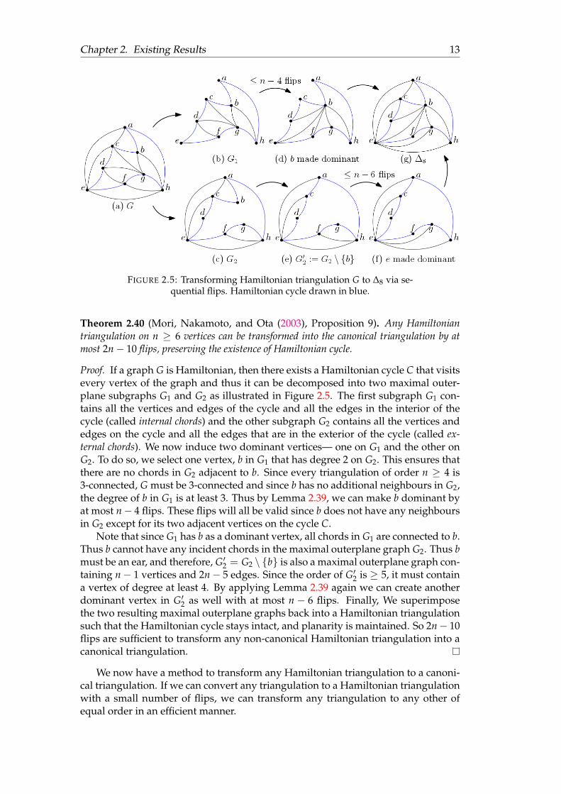
FIGURE 2.5: Transforming Hamiltonian triangulation G to ∆8 via se-quential flips. Hamiltonian cycle drawn in blue.
Theorem 2.40 (Mori, Nakamoto, and Ota (2003), Proposition 9). Any Hamiltoniantriangulation on n ≥ 6 vertices can be transformed into the canonical triangulation by atmost 2n− 10 flips, preserving the existence of Hamiltonian cycle.
Proof. If a graph G is Hamiltonian, then there exists a Hamiltonian cycle C that visitsevery vertex of the graph and thus it can be decomposed into two maximal outer-plane subgraphs G1 and G2 as illustrated in Figure 2.5. The first subgraph G1 con-tains all the vertices and edges of the cycle and all the edges in the interior of thecycle (called internal chords) and the other subgraph G2 contains all the vertices andedges on the cycle and all the edges that are in the exterior of the cycle (called ex-ternal chords). We now induce two dominant vertices— one on G1 and the other onG2. To do so, we select one vertex, b in G1 that has degree 2 on G2. This ensures thatthere are no chords in G2 adjacent to b. Since every triangulation of order n ≥ 4 is3-connected, G must be 3-connected and since b has no additional neighbours in G2,the degree of b in G1 is at least 3. Thus by Lemma 2.39, we can make b dominant byat most n− 4 flips. These flips will all be valid since b does not have any neighboursin G2 except for its two adjacent vertices on the cycle C.
Note that since G1 has b as a dominant vertex, all chords in G1 are connected to b.Thus b cannot have any incident chords in the maximal outerplane graph G2. Thus bmust be an ear, and therefore, G′2 = G2 \ b is also a maximal outerplane graph con-taining n− 1 vertices and 2n− 5 edges. Since the order of G′2 is ≥ 5, it must containa vertex of degree at least 4. By applying Lemma 2.39 again we can create anotherdominant vertex in G′2 as well with at most n − 6 flips. Finally, We superimposethe two resulting maximal outerplane graphs back into a Hamiltonian triangulationsuch that the Hamiltonian cycle stays intact, and planarity is maintained. So 2n− 10flips are sufficient to transform any non-canonical Hamiltonian triangulation into acanonical triangulation.
We now have a method to transform any Hamiltonian triangulation to a canoni-cal triangulation. If we can convert any triangulation to a Hamiltonian triangulationwith a small number of flips, we can transform any triangulation to any other ofequal order in an efficient manner.
Chapter 2. Existing Results 14
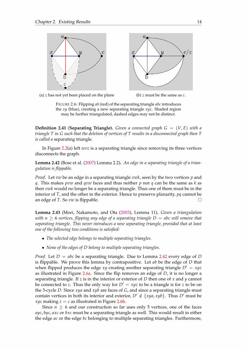
(a) z has not yet been placed on the plane (b) z must be the same as c.
FIGURE 2.6: Flipping ab (red) of the separating triangle abc introducesthe xy (blue), creating a new separating triangle xyz. Shaded region
may be further triangulated, dashed edges may not be distinct.
Definition 2.41 (Separating Triangle). Given a connected graph G = (V, E) with atriangle T in G such that the deletion of vertices of T results in a disconnected graph then Tis called a separating triangle.
In Figure 2.2(a) left wvz is a separating triangle since removing its three verticesdisconnects the graph.
Lemma 2.42 (Bose et al. (2007) Lemma 2.2). An edge in a separating triangle of a trian-gulation is flippable.
Proof. Let vw be an edge in a separating triangle vwk, seen by the two vertices p andq. This makes pvw and qvw faces and thus neither p nor q can be the same as k asthen vwk would no longer be a separating triangle. Thus one of them must be in theinterior of T, and the other in the exterior. Hence to preserve planarity, pq cannot bean edge of T. So vw is flippable.
Lemma 2.43 (Mori, Nakamoto, and Ota (2003), Lemma 11). Given a triangulationwith n ≥ 6 vertices, flipping any edge of a separating triangle D = abc will remove thatseparating triangle. This never introduces a new separating triangle, provided that at leastone of the following two conditions is satisfied:
• The selected edge belongs to multiple separating triangles.
• None of the edges of D belong to multiple separating triangles.
Proof. Let D = abc be a separating triangle. Due to Lemma 2.42 every edge of Dis flippable. We prove this lemma by contrapositive. Let ab be the edge of D thatwhen flipped produces the edge xy creating another separating triangle D′ = xyzas illustrated in Figure 2.6a. Since the flip removes an edge of D, it is no longer aseparating triangle. If z is in the interior or exterior of D then one of x and y cannotbe connected to z. Thus the only way for D′ = xyz to be a triangle is for z to be onthe 3-cycle D. Since xya and xyb are faces of G, and since a separating triangle mustcontain vertices in both its interior and exterior, D′ /∈ xya, xyb. Thus D′ must bexyc making z = c as illustrated in Figure 2.6b.
Since n ≥ 6 and our construction so far uses only 5 vertices, one of the facesayc, byc, axc or bxc must be a separating triangle as well. This would result in eitherthe edge ac or the edge bc belonging to multiple separating triangles. Furthermore,

Chapter 2. Existing Results 15
because a is outside the cycle (x, y, c) while b is inside, they cannot both be neigh-bours of any other vertices apart from x, y and c. Since abx and aby are faces, andabc = D, ab cannot be part of any other separating triangle while at least one of bcand ca is—which is the negation of the premise.
Lemma 2.44 (Mori, Nakamoto, and Ota (2003), Lemma 10). Any triangulation on nvertices can be made 4-connected by at most n− 4 flips.
Proof. The proof is done by induction on n. The base case can be obtained for n = 4giving us a K4 graph which contains no separating triangles, and we do not needany flips at all. For the induction step, let us assume that our graph G with a fixedouterface has a separating triangle T that divides the graph into two induced sub-graphs G1 := G \ int(T) and G2 := G \ ext(T).1 By induction, both G1 and G2 haveat most n1 − 4 and n2 − 4 separating triangles respectively where n1 is the numberof vertices in G1 and n2 is the number of vertices in G2. Since the separating trianglethat divides the graph into G1 and G2 does not contribute to any separating trianglesin either of them, G can have at most n1− 4+ n2− 4+ 1 = (n1 + n2− 3)− 4 = n− 4separating triangles. So n − 4 flips are sufficient to break all separating triangles.Since any triangulation without separating triangles is at least 4-connected the re-sult follows by using Lemma 2.43.
Theorem 2.45 (Mori, Nakamoto, and Ota (2003), Theorem 4). Any two triangulationson n ≥ 6 vertices can be transformed into each other by at most 6n− 30 flips.
Proof. Since every face of a triangulation is a 3-cycle, no triangulation can be madedisconnected by deleting less than 3 vertices— making all triangulations 3-connected.A triangulation of order ≥ 4 with no separating triangles cannot be made discon-nected by deleting 3 vertices and thus any such triangulation is 4-connected. Whit-ney (1931) proves that a 4-connected triangulation is Hamiltonian. So we can useTheorem 2.40 to transform this Hamiltonian triangulation G into the canonical tri-angulation using 2n − 10 flips. Theorem 2.40 begins by applying Lemma 2.39 tointroduce a dominant vertex v using n − 1− deg(v) flips. Note that G is not onlyHamiltonian, it is also 4-connected. Thus every vertex of G must have a degree ofat least 4 (instead of 3). Thus Lemma 2.39 would require at most n − 5 flips (in-stead of n − 4 as counted in Theorem 2.40) to introduce the first dominant vertex.Thus using Theorem 2.40 we would only need at most 2n − 11 flips to convert Ginto ∆n. And the total number of flips required to transform any triangulation withn ≥ 6 vertices to the Hamiltonian triangulation and then the canonical triangulationis (n− 4) + (2n− 11) = 3n− 15 flips.
Finally, to transform any triangulation of n ≥ 6 vertices to any other triangu-lation of equal order, we first follow the sequence of flips to transform the firsttriangulation to ∆n. Then we transform ∆n to the second triangulation, by apply-ing the reverse sequence of the flips required to transform the second triangula-tion to ∆n. The total number of flips required for the transformation is at most(3n− 15)× 2 = 6n− 30.
2.2.3 Other Bounds
Bose et al. (2014) prove that bound on the number of flips provided by Mori, Nakamoto,and Ota (2003) is not tight. They give a tighter bound stating that (3n−6)
5 flips are
1Vertices of T are not present in either of G1 and G2.
Chapter 2. Existing Results 16
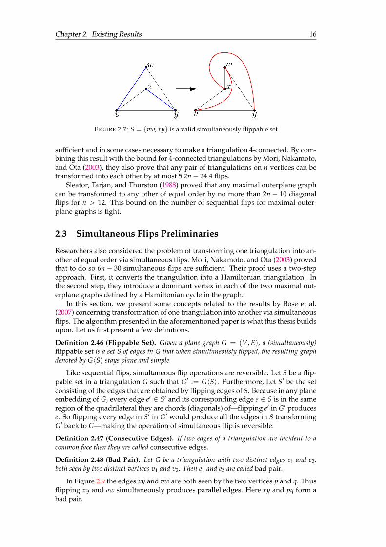
FIGURE 2.7: S = vw, xy is a valid simultaneously flippable set
sufficient and in some cases necessary to make a triangulation 4-connected. By com-bining this result with the bound for 4-connected triangulations by Mori, Nakamoto,and Ota (2003), they also prove that any pair of triangulations on n vertices can betransformed into each other by at most 5.2n− 24.4 flips.
Sleator, Tarjan, and Thurston (1988) proved that any maximal outerplane graphcan be transformed to any other of equal order by no more than 2n − 10 diagonalflips for n > 12. This bound on the number of sequential flips for maximal outer-plane graphs is tight.
2.3 Simultaneous Flips Preliminaries
Researchers also considered the problem of transforming one triangulation into an-other of equal order via simultaneous flips. Mori, Nakamoto, and Ota (2003) provedthat to do so 6n− 30 simultaneous flips are sufficient. Their proof uses a two-stepapproach. First, it converts the triangulation into a Hamiltonian triangulation. Inthe second step, they introduce a dominant vertex in each of the two maximal out-erplane graphs defined by a Hamiltonian cycle in the graph.
In this section, we present some concepts related to the results by Bose et al.(2007) concerning transformation of one triangulation into another via simultaneousflips. The algorithm presented in the aforementioned paper is what this thesis buildsupon. Let us first present a few definitions.
Definition 2.46 (Flippable Set). Given a plane graph G = (V, E), a (simultaneously)flippable set is a set S of edges in G that when simultaneously flipped, the resulting graphdenoted by G〈S〉 stays plane and simple.
Like sequential flips, simultaneous flip operations are reversible. Let S be a flip-pable set in a triangulation G such that G′ := G〈S〉. Furthermore, Let S′ be the setconsisting of the edges that are obtained by flipping edges of S. Because in any planeembedding of G, every edge e′ ∈ S′ and its corresponding edge e ∈ S is in the sameregion of the quadrilateral they are chords (diagonals) of—flipping e′ in G′ producese. So flipping every edge in S′ in G′ would produce all the edges in S transformingG′ back to G—making the operation of simultaneous flip is reversible.
Definition 2.47 (Consecutive Edges). If two edges of a triangulation are incident to acommon face then they are called consecutive edges.
Definition 2.48 (Bad Pair). Let G be a triangulation with two distinct edges e1 and e2,both seen by two distinct vertices v1 and v2. Then e1 and e2 are called bad pair.
In Figure 2.9 the edges xy and vw are both seen by the two vertices p and q. Thusflipping xy and vw simultaneously produces parallel edges. Here xy and pq form abad pair.
Chapter 2. Existing Results 17
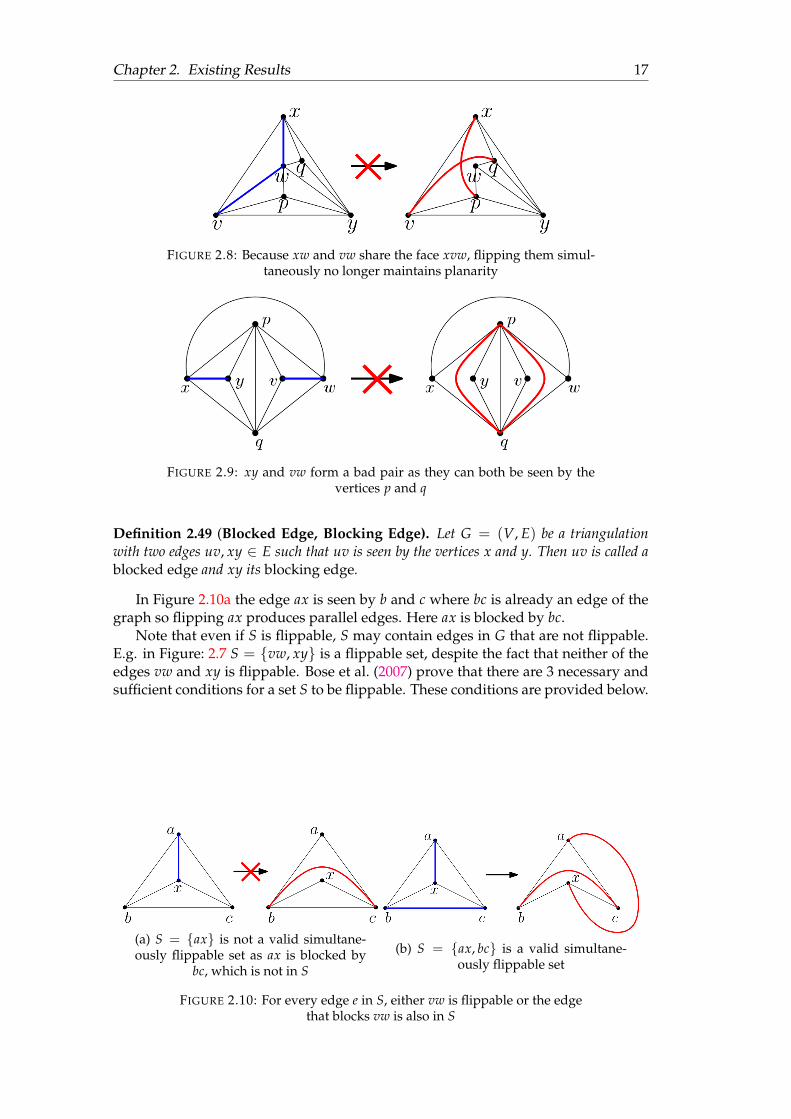
FIGURE 2.8: Because xw and vw share the face xvw, flipping them simul-taneously no longer maintains planarity
FIGURE 2.9: xy and vw form a bad pair as they can both be seen by thevertices p and q
Definition 2.49 (Blocked Edge, Blocking Edge). Let G = (V, E) be a triangulationwith two edges uv, xy ∈ E such that uv is seen by the vertices x and y. Then uv is called ablocked edge and xy its blocking edge.
In Figure 2.10a the edge ax is seen by b and c where bc is already an edge of thegraph so flipping ax produces parallel edges. Here ax is blocked by bc.
Note that even if S is flippable, S may contain edges in G that are not flippable.E.g. in Figure: 2.7 S = vw, xy is a flippable set, despite the fact that neither of theedges vw and xy is flippable. Bose et al. (2007) prove that there are 3 necessary andsufficient conditions for a set S to be flippable. These conditions are provided below.
(a) S = ax is not a valid simultane-ously flippable set as ax is blocked by
bc, which is not in S
(b) S = ax, bc is a valid simultane-ously flippable set
FIGURE 2.10: For every edge e in S, either vw is flippable or the edgethat blocks vw is also in S
Chapter 2. Existing Results 18
Lemma 2.50 (Bose et al. (2007) Lemma 2.1). A set of edges S in a triangulation G 6= K3is flippable if and only if:
1. no two edges in S are consecutive,
2. no two edges in S form a bad pair, and
3. for every edge vw ∈ S either vw is flippable, or the edge that blocks vw is also in S.
Proof. ⇐ Every edge in a triangulation lies on two faces, which form a quadrilat-eral. When an edge is flipped, the new edge is placed in between the edges of thequadrilateral in their corresponding connecting vertices’ cyclic order. As illustratedin Figure 2.8, when two consecutive edges xw and vw seen by q, v and x, p re-spectively are flipped we get vq and xp—each passing through the interior of thecycle (x, q, w, p, v). Notice that the new edge vq separates the two points x and pin the interior of the cycle (x, q, w, p, v), denying the edge (internal chord) xp in theinterior of the cycle. This is why when consecutive edges are flipped, their corre-sponding flipped edges (vq and xp) intersect destroying the planarity of the newgraph.
When two edges forming a bad pair are flipped simultaneously, it produces par-allel edges—which is not allowed in simple graphs. E.g. in Figure 2.9 the edges xyand vw form a bad pair because they can both be seen by p and q, resulting in boththeir flipped edges to be pq.
Finally, if an edge of the set S is blocked by another edge in the graph, then toavoid parallel edges in the new graph obtained by flipping the edges of the set, theblocking edge must be removed by inserting it also in the set. In Figure 2.10a we seethat the edge ax is blocked by the edge bc. Clearly for ax to be flipped we must alsoflip bc, as shown in Figure 2.10b. Thus all three conditions listed in the lemma arenecessary.
Proof. ⇒We now show that given a triangulation G, these conditions are sufficient.Since no two edges in S are consecutive, G〈S〉 is a graph embedded in the plane andevery face is a triangle. Suppose two edges e1 and e2 are parallel in G〈S〉. Since Gdoes not have parallel edges, not both of e1 and e2 are in G. If exactly one of e1 ande2 is in G, then Condition 3 fails. If neither of e1 and e2 is in G, then the edges in Sthat are flipped to e1 and e2 form a bad pair. So these conditions are also sufficientfor S to be flippable.
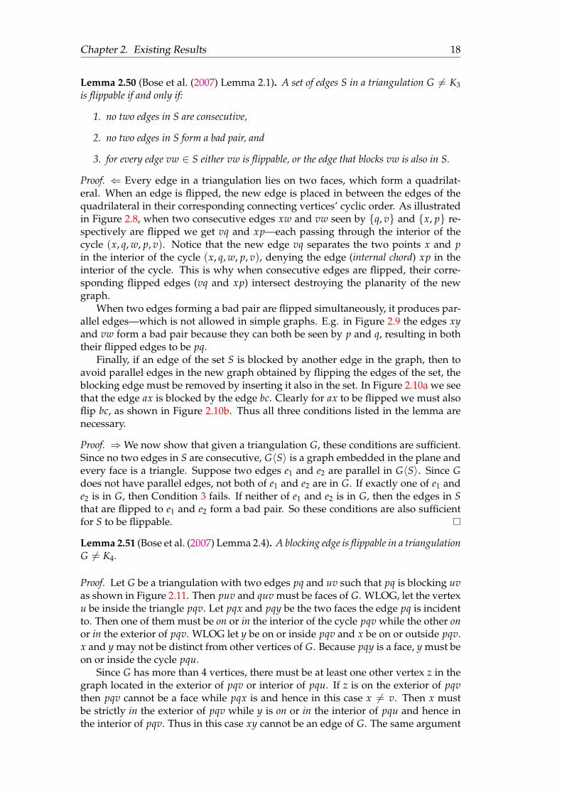
Lemma 2.51 (Bose et al. (2007) Lemma 2.4). A blocking edge is flippable in a triangulationG 6= K4.
Proof. Let G be a triangulation with two edges pq and uv such that pq is blocking uvas shown in Figure 2.11. Then puv and quv must be faces of G. WLOG, let the vertexu be inside the triangle pqv. Let pqx and pqy be the two faces the edge pq is incidentto. Then one of them must be on or in the interior of the cycle pqv while the other onor in the exterior of pqv. WLOG let y be on or inside pqv and x be on or outside pqv.x and y may not be distinct from other vertices of G. Because pqy is a face, y must beon or inside the cycle pqu.
Since G has more than 4 vertices, there must be at least one other vertex z in thegraph located in the exterior of pqv or interior of pqu. If z is on the exterior of pqvthen pqv cannot be a face while pqx is and hence in this case x 6= v. Then x mustbe strictly in the exterior of pqv while y is on or in the interior of pqu and hence inthe interior of pqv. Thus in this case xy cannot be an edge of G. The same argument
Chapter 2. Existing Results 19
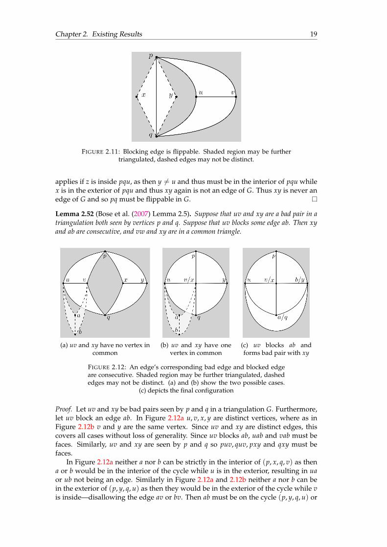
FIGURE 2.11: Blocking edge is flippable. Shaded region may be furthertriangulated, dashed edges may not be distinct.
applies if z is inside pqu, as then y 6= u and thus must be in the interior of pqu whilex is in the exterior of pqu and thus xy again is not an edge of G. Thus xy is never anedge of G and so pq must be flippable in G.
Lemma 2.52 (Bose et al. (2007) Lemma 2.5). Suppose that uv and xy are a bad pair in atriangulation both seen by vertices p and q. Suppose that uv blocks some edge ab. Then xyand ab are consecutive, and vw and xy are in a common triangle.
(a) uv and xy have no vertex incommon
(b) uv and xy have onevertex in common
(c) uv blocks ab andforms bad pair with xy
FIGURE 2.12: An edge’s corresponding bad edge and blocked edgeare consecutive. Shaded region may be further triangulated, dashededges may not be distinct. (a) and (b) show the two possible cases.
(c) depicts the final configuration
Proof. Let uv and xy be bad pairs seen by p and q in a triangulation G. Furthermore,let uv block an edge ab. In Figure 2.12a u, v, x, y are distinct vertices, where as inFigure 2.12b v and y are the same vertex. Since uv and xy are distinct edges, thiscovers all cases without loss of generality. Since uv blocks ab, uab and vab must befaces. Similarly, uv and xy are seen by p and q so puv, quv, pxy and qxy must befaces.
In Figure 2.12a neither a nor b can be strictly in the interior of (p, x, q, v) as thena or b would be in the interior of the cycle while u is in the exterior, resulting in uaor ub not being an edge. Similarly in Figure 2.12a and 2.12b neither a nor b can bein the exterior of (p, y, q, u) as then they would be in the exterior of the cycle while vis inside—disallowing the edge av or bv. Then ab must be on the cycle (p, y, q, u) or
Chapter 2. Existing Results 20
(p, x, q, v). Because u and v can see ab, neither of the vertices a and b can be the sameas u or v. Then a, b ⊂ p, q, x, y.
Let us assume that ab = pq. If pq exists in G, it must either be in interior of thecycle (p, x, q, v) (Figure 2.12a), or in the exterior of the cycle (p, y, q, v) (Figure 2.12aand 2.12b). If pq lies in the interior of (p, x, q, v) then uab cannot be a face as u lieson the exterior of the cycle. Similarly if pq lies on the exterior of (p, y, q, v) then vabcannot be a face as v lies in the interior of the cycle. Thus ab 6= pq and as a result atleast one of the vertices between a and b must be distinct from p and q.
WLOG let a be the vertex distinct from p and q. Then a ∈ x, y.In Figure 2.12a, if a = x then au cannot be an edge as a and u would be separated
by the cycle (p, y, q, v). Similarly a 6= y as the cycle (p, x, q, u) would separate a fromv denying the edge av. Thus this case is impossible and uv and xy must have acommon vertex.
In Figure 2.12b the only remaining candidate for a is x. Let a = x. Then ua = uxmust be an edge. WLOG let b be q. Then qx = ab is blocked by uv. Finally, since xvqis a face, ab is consecutive to vx = xy as illustrated in Figure 2.12c.
2.4 Transforming Triangulations in O(log n) SimultaneousFlips
In this section, we explain the algorithm of Bose et al. (2007) for transforming anytriangulation to any other using logarithmic number of simultaneous flips. First, inSection 2.4.1 we show that Ω(log n) is necessary. Then we start with some definitionsand a few important lemmas and conclude the chapter with a detailed explanationof the algorithm.
2.4.1 Necessity of Ω(log n) Simultaneous Flips
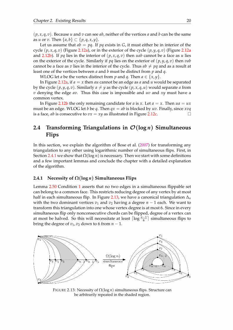
Lemma 2.50 Condition 1 asserts that no two edges in a simultaneous flippable setcan belong to a common face. This restricts reducing degree of any vertex by at mosthalf in each simultaneous flip. In Figure 2.13, we have a canonical triangulation ∆nwith the two dominant vertices v1 and v2 having a degree n− 1 each. We want totransform this triangulation into one whose vertex degree is at most 6. Since in everysimultaneous flip only nonconsecutive chords can be flipped, degree of a vertex canat most be halved. So this will necessitate at least dlog n−1
6 e simultaneous flips tobring the degree of v1, v2 down to 6 from n− 1.
FIGURE 2.13: Necessity of Ω(log n) simultaneous flips. Structure canbe arbitrarily repeated in the shaded region.

Chapter 2. Existing Results 21
2.4.2 Related Definitions
Definition 2.53 (Empty Cycle). An empty region is a region that does not contain anyvertex strictly in its interior. A cycle C of a plane graph G is an empty cycle if one of itstwo regions is empty and is assigned as its local region. The other region is referred to asthe foreign region of the empty cycle.
If an empty cycle neither contains any vertices in its interior nor in its exterior,then it must be a Hamiltonian cycle passing through all the vertices. Thus all Hamil-tonian cycles define empty cycles. In fact, a Hamiltonian cycle defines two emptycycles—one is the cycle and its empty interior region as its local region, and the otheris the cycle and its empty exterior region as its local region. In Chapters 2 and 3 nofigure requires defining more than one empty cycle. So in all the figures the embed-ding is chosen such that the local region of the empty cycle is always in the interiorof the cycle.
Definition 2.54 (k-regular). A graph G = (V, E) is called a k-regular graph if for allvertices v ∈ V, deg(v) = k.
Definition 2.55 (Connected Components). Given a graph G = (V, E), a connectedcomponent or in short component, of G is a subgraph of G in which any two vertices areconnected by paths, and which is connected to no additional vertices in the supergraph.
Definition 2.56 (Bridge). Given a graph G = (V, E), an edge e ∈ E, deletion of whichincreases the number of components in G, is called a bridge.
Definition 2.57 (Dual Graph). Given a graph G = (V, E) with its set of faces F, the dualgraph G∗ = (V∗, E∗) of G is also a graph with a bijection between F and V∗, and anotherbijection between E and E∗, such that for every edge e ∈ E on two faces fi, f j ∈ F and itscorresponding edge e∗ ∈ E∗, e∗ = v∗1v∗2 where v∗i , v∗j ∈ V∗ are the corresponding vertices ofthe faces fi and f j.
The dual graph connects two vertices IFF their corresponding faces in the primalgraph share a region. Thus given a plane embedding of the primal graph, if weplace the vertices of the dual graph in the interior of their corresponding faces of theprimal graph, no edges of the dual graph would intersect each other except at theirendpoints—making the dual graph of any planar graph planar.
Also, note that a dual graph of any planar graph is not necessarily simple as itis possible for a plane graph to have two faces having multiple edges in common,producing parallel edges in the dual graph. Or if a planar graph contains a bridge,it would produce a loop in its dual graph. However, since a triangulation cannothave a bridge, its dual graph cannot have loops. For a dual graph of a triangulationto have parallel edges, the primal triangulation must have two faces sharing at leasttwo edges. For two triangles T1 and T2 to share two edges uv and vw, both thetriangles must be described by the cycle (u, v, w). Since a triangulation can haveonly one (u, v, w) cycle and since the only case (u, v, w) is a face in its interior as wellas in its exterior is when the triangulation has exactly 3 vertices, dual graph of anytriangulation of order > 3 cannot have parallel edges. Since we do not refer to thedual graph of a triangle, every graph in this thesis is simple.
Definition 2.58 (Dual Tree). The dual tree G∗ of a maximal outerplane graph G is thedual graph of G without the vertex corresponding to the outerface of G.
A maximal outerplane graph has n− 3 chords and n− 2 faces excluding its out-erface. Since every face excepting the outerface is a triangle, its dual tree must be

Chapter 2. Existing Results 22
FIGURE 2.14: The dual tree of the maximal outerplane graph is drawn inblue.
connected, have n− 3 edges and n− 2 vertices. Thus the dual tree must be a tree—which is also a simple graph. An example of a dual tree is illustrated in Figure 2.14.Any vertex of degree 1 in a tree is called a leaf .
Definition 2.59 (Matching). Given a connected graph G = (V, E), an edge set S forms amatching in G if no two edges in S are connected to the same vertex in V.
It may be noted that Condition 1 of Lemma 2.50 is equivalent to stating that theedges of the dual tree G∗ (see Definition 2.58) that correspond to the edges of theflippable set S form a matching.
Definition 2.60 (Perfect Matching). Given a connected graph G = (V, E) and a match-ing S, S is a perfect matching if every vertex in V is connected to an edge in S.
Definition 2.61 (Independent Set). Given a connected graph G = (V, E) an indepen-dent set is a subset of pairwise non-adjacent vertices of V in G.
Definition 2.62 (Ear). Given an outerplane graph G = (V, E), an ear of G is a 3-cycle facewith 2 of its edges on the maximal cycle of G.
2.4.3 Related Lemmas
The result of the following set of lemmas leads to the correctness of the algorithm byBose et al. (2007).
The next lemma establishes a strong relationship between a flip set of a maximalouterplane graph and its corresponding edge set in the graph’s dual tree.
Lemma 2.63 (Bose et al. (2007) Lemma 4.2). A set S of internal edges in a maximal out-erplane graph G is flippable if and only if the corresponding dual edges S∗ form a matchingin the dual tree G∗.
Proof. ⇐ Let S∗ form a matching in the dual tree G∗. Then no two edges of S∗ canhave a common vertex. Thus no two edges of S can have a common face in theprimal outerplane graph G—making edges of S pairwise non-consecutive. Since Gis a maximal outerplane graph, due to Lemma 2.38 no edges in S can be blocked.Furthermore, for two edges ab, xy ∈ S to form a bad pair, they must be seen bythe vertices p and q. Then the subgraph induced by the vertices a, b, x, y, p, q mustform a subdivision of K4. Since an outerplane graph can contain neither K4 nor itssubdivision, this cannot happen. Thus due to Lemma 2.50 S must be flippable.
Chapter 2. Existing Results 23
Proof. ⇒ Let S be a simultaneously flippable set in G. Then due to Lemma 2.50, notwo edges of S can share the same face. Then in the corresponding flip set S∗ inthe dual tree G∗, no two edges can share the same vertex—making S∗ a matching inG∗.
The next lemma shows that any set of edges S of a triangulation can be 3-coloured.Given any set S of a triangulation G, the lemma provides us a way to select at leasta third of the edges in S such that they are pairwise non-consecutive.
Lemma 2.64 (Bose et al. (2007) Lemma 3.6). Every n-vertex planar graph G has an edge3-colouring that can be computed in O(n2) time, such that every triangle is trichromatic(edges coloured with 3 different colours).
Proof. Robertson et al. (1997) proved that the vertices of G can be coloured with nomore than 4-colours such that no two neighbouring vertices have the same colour.For such a solution, let the 4 colours be 1, 2, 3, 4. Now for each triangle in G, wecolour each edge e in G in the following manner:
• Colours of the vertices e connects to are 1, 2, or 3, 4 =⇒ colour e as red.
• Colours of the vertices e connects to are 1, 3, or 2, 4 =⇒ colour e as green.
• Colours of the vertices e connects to are 1, 4, or 2, 3 =⇒ colour e as blue.
Since no two vertices of the same colour can be neighbours, the only way twoedges uv and xy on the same triangle can have the same colour is when all u, v, xand y are coloured differently. But since uv and xy are on a common triangle, theymust have a vertex in common—disallowing them from having 4 distinct colours.Hence the edges of each triangle must be trichromatic.
The next lemma provides an upper bound on the number of simultaneous flipsrequired to make any vertex dominant in a maximal outerplane graph. Notice thatthe concept of diagonal flips and flippable sets stay valid in outerplane graphs solong as we are flipping internal chords and not edges incident to the outerplane. Anouterplane graph on n vertices with a dominant vertex is referred as Dn. Since allouterplane graphs of equal order with a dominant vertex are isomorphic, once wecan transform any outerplane graph to Dn using simultaneous flips, we can trans-form any outerplane graph to another of equal order using the same technique. Ob-serve that a flip in an outerplane graph is equivalent to a rotation in its dual tree(see Chen, Chang, and Wang (2005), Pallo (2000), Pallo (1987), Sleator, Tarjan, andThurston (1988)).
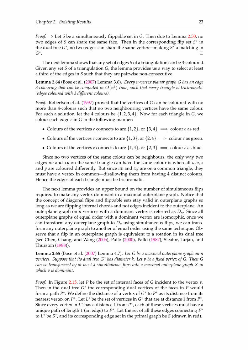
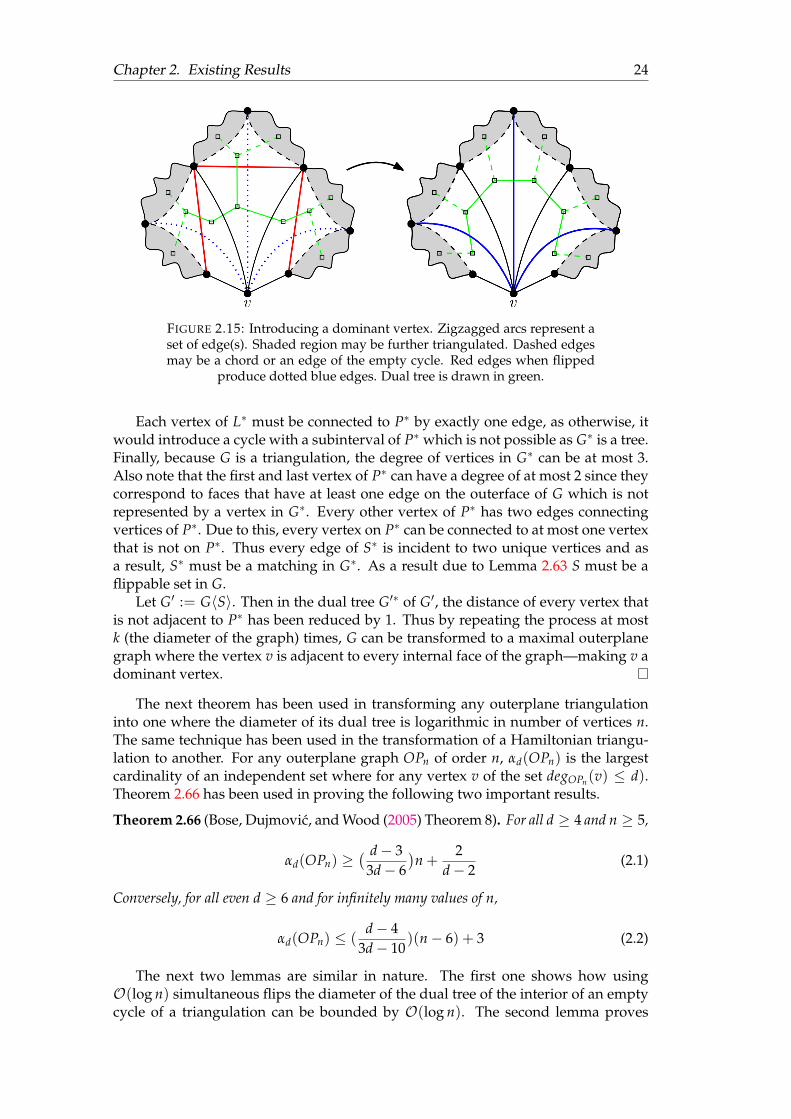
Lemma 2.65 (Bose et al. (2007) Lemma 4.7). Let G be a maximal outerplane graph on nvertices. Suppose that its dual tree G∗ has diameter k. Let v be a fixed vertex of G. Then Gcan be transformed by at most k simultaneous flips into a maximal outerplane graph X inwhich v is dominant.
Proof. In Figure 2.15, let P be the set of internal faces of G incident to the vertex v.Then in the dual tree G∗ the corresponding dual vertices of the faces in P wouldform a path P∗. We define the distance of a vertex of G∗ to P∗ as its distance from itsnearest vertex on P∗. Let L∗ be the set of vertices in G∗ that are at distance 1 from P∗.Since every vertex in L∗ has a distance 1 from P∗, each of these vertices must have aunique path of length 1 (an edge) to P∗. Let the set of all these edges connecting P∗
to L∗ be S∗, and its corresponding edge set in the primal graph be S (drawn in red).
Chapter 2. Existing Results 24
FIGURE 2.15: Introducing a dominant vertex. Zigzagged arcs represent aset of edge(s). Shaded region may be further triangulated. Dashed edgesmay be a chord or an edge of the empty cycle. Red edges when flipped
produce dotted blue edges. Dual tree is drawn in green.
Each vertex of L∗ must be connected to P∗ by exactly one edge, as otherwise, itwould introduce a cycle with a subinterval of P∗ which is not possible as G∗ is a tree.Finally, because G is a triangulation, the degree of vertices in G∗ can be at most 3.Also note that the first and last vertex of P∗ can have a degree of at most 2 since theycorrespond to faces that have at least one edge on the outerface of G which is notrepresented by a vertex in G∗. Every other vertex of P∗ has two edges connectingvertices of P∗. Due to this, every vertex on P∗ can be connected to at most one vertexthat is not on P∗. Thus every edge of S∗ is incident to two unique vertices and asa result, S∗ must be a matching in G∗. As a result due to Lemma 2.63 S must be aflippable set in G.
Let G′ := G〈S〉. Then in the dual tree G′∗ of G′, the distance of every vertex thatis not adjacent to P∗ has been reduced by 1. Thus by repeating the process at mostk (the diameter of the graph) times, G can be transformed to a maximal outerplanegraph where the vertex v is adjacent to every internal face of the graph—making v adominant vertex.
The next theorem has been used in transforming any outerplane triangulationinto one where the diameter of its dual tree is logarithmic in number of vertices n.The same technique has been used in the transformation of a Hamiltonian triangu-lation to another. For any outerplane graph OPn of order n, αd(OPn) is the largestcardinality of an independent set where for any vertex v of the set degOPn(v) ≤ d).Theorem 2.66 has been used in proving the following two important results.
Theorem 2.66 (Bose, Dujmovic, and Wood (2005) Theorem 8). For all d ≥ 4 and n ≥ 5,
αd(OPn) ≥( d− 3
3d− 6)n +
2d− 2
(2.1)
Conversely, for all even d ≥ 6 and for infinitely many values of n,
αd(OPn) ≤ (d− 4
3d− 10)(n− 6) + 3 (2.2)
The next two lemmas are similar in nature. The first one shows how usingO(log n) simultaneous flips the diameter of the dual tree of the interior of an emptycycle of a triangulation can be bounded by O(log n). The second lemma proves
Chapter 2. Existing Results 25
the same statement for maximal outerplane graphs. Given a plane graph G and anempty cycle C, GC denotes the subgraph of G whose vertices are the vertices of Cand whose edges are the edges of C along with the internal chords of C.
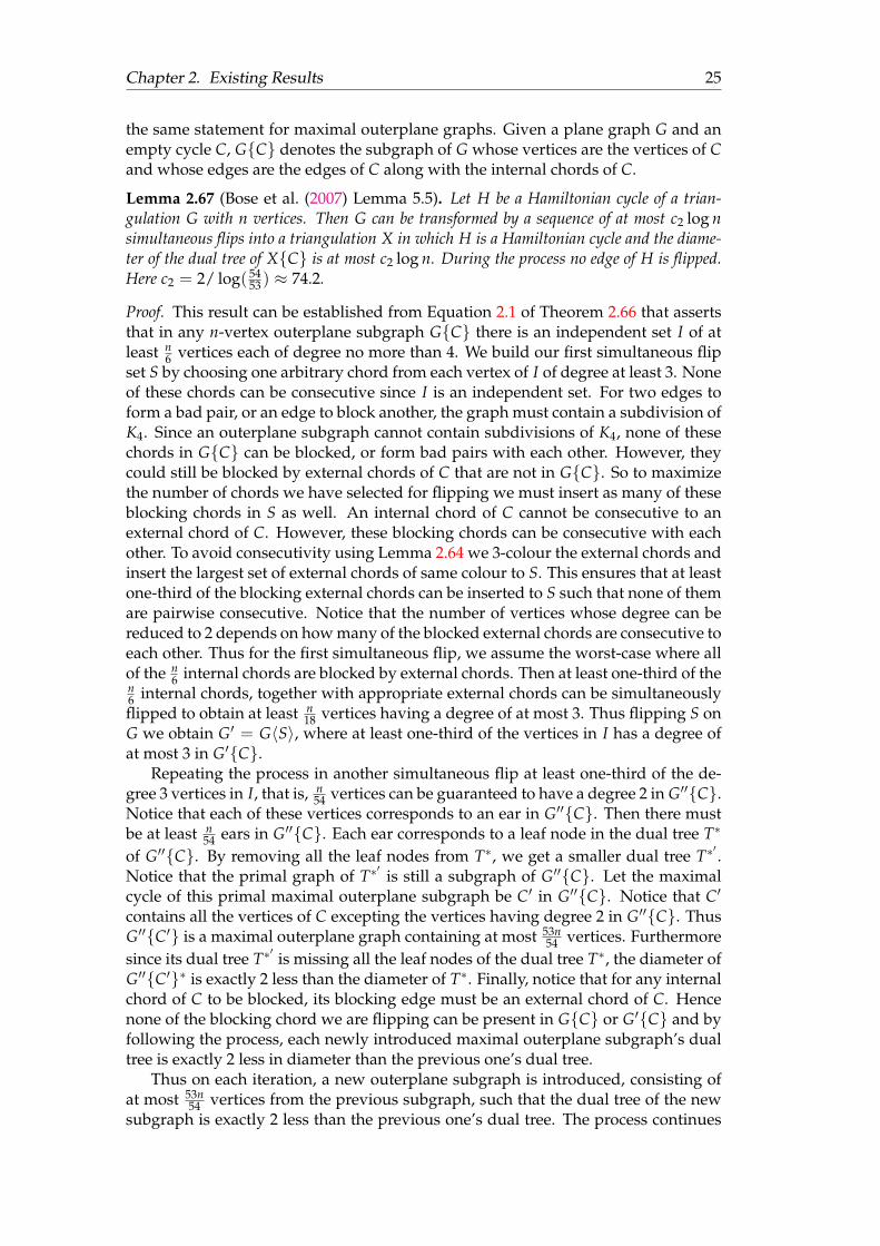
Lemma 2.67 (Bose et al. (2007) Lemma 5.5). Let H be a Hamiltonian cycle of a trian-gulation G with n vertices. Then G can be transformed by a sequence of at most c2 log nsimultaneous flips into a triangulation X in which H is a Hamiltonian cycle and the diame-ter of the dual tree of XC is at most c2 log n. During the process no edge of H is flipped.Here c2 = 2/ log( 54
53 ) ≈ 74.2.
Proof. This result can be established from Equation 2.1 of Theorem 2.66 that assertsthat in any n-vertex outerplane subgraph GC there is an independent set I of atleast n
6 vertices each of degree no more than 4. We build our first simultaneous flipset S by choosing one arbitrary chord from each vertex of I of degree at least 3. Noneof these chords can be consecutive since I is an independent set. For two edges toform a bad pair, or an edge to block another, the graph must contain a subdivision ofK4. Since an outerplane subgraph cannot contain subdivisions of K4, none of thesechords in GC can be blocked, or form bad pairs with each other. However, theycould still be blocked by external chords of C that are not in GC. So to maximizethe number of chords we have selected for flipping we must insert as many of theseblocking chords in S as well. An internal chord of C cannot be consecutive to anexternal chord of C. However, these blocking chords can be consecutive with eachother. To avoid consecutivity using Lemma 2.64 we 3-colour the external chords andinsert the largest set of external chords of same colour to S. This ensures that at leastone-third of the blocking external chords can be inserted to S such that none of themare pairwise consecutive. Notice that the number of vertices whose degree can bereduced to 2 depends on how many of the blocked external chords are consecutive toeach other. Thus for the first simultaneous flip, we assume the worst-case where allof the n
6 internal chords are blocked by external chords. Then at least one-third of then6 internal chords, together with appropriate external chords can be simultaneouslyflipped to obtain at least n
18 vertices having a degree of at most 3. Thus flipping S onG we obtain G′ = G〈S〉, where at least one-third of the vertices in I has a degree ofat most 3 in G′C.
Repeating the process in another simultaneous flip at least one-third of the de-gree 3 vertices in I, that is, n
54 vertices can be guaranteed to have a degree 2 in G′′C.Notice that each of these vertices corresponds to an ear in G′′C. Then there mustbe at least n
54 ears in G′′C. Each ear corresponds to a leaf node in the dual tree T∗
of G′′C. By removing all the leaf nodes from T∗, we get a smaller dual tree T∗′.
Notice that the primal graph of T∗′
is still a subgraph of G′′C. Let the maximalcycle of this primal maximal outerplane subgraph be C′ in G′′C. Notice that C′
contains all the vertices of C excepting the vertices having degree 2 in G′′C. ThusG′′C′ is a maximal outerplane graph containing at most 53n
54 vertices. Furthermoresince its dual tree T∗
′is missing all the leaf nodes of the dual tree T∗, the diameter of
G′′C′∗ is exactly 2 less than the diameter of T∗. Finally, notice that for any internalchord of C to be blocked, its blocking edge must be an external chord of C. Hencenone of the blocking chord we are flipping can be present in GC or G′C and byfollowing the process, each newly introduced maximal outerplane subgraph’s dualtree is exactly 2 less in diameter than the previous one’s dual tree.
Thus on each iteration, a new outerplane subgraph is introduced, consisting ofat most 53n
54 vertices from the previous subgraph, such that the dual tree of the newsubgraph is exactly 2 less than the previous one’s dual tree. The process continues

Chapter 2. Existing Results 26
until the size of the graph is smaller than 6. Therefore, the recurrence relation2 weget over the diameter gives us 2 + c2 log 53n
54 = c2 log n. Similarly, in every iteration,we require 2 simultaneous flips and the recurrence relation over the number of si-multaneous flips is the same as well. Thus with no more than c2 log n simultaneousflips we can transform G into X such that the diameter of the dual tree of XC isno more than c2 log n, where c2 = 2
log 5453
.
Lemma 2.68 (Bose et al. (2007) Lemma 4.6). Let G be a maximal outerplane graph on nvertices. Then G can be transformed by a sequence of at most c1 log n simultaneous flips intoa maximal outerplane graph X such that the diameter of the dual tree X∗ is at most c1 log n.During the process the edges of the maximal cycle of G is preserved. [c1 = 2
log 65≈ 7.6 log n]
Proof. This lemma is an outcome of Lemma 2.67. The difference being that inLemma 2.67, the internal chords selected could be blocked by external chords butin a maximal outerplane graph, the maximal cycle does not contain any externalchords.
Like before using Equation 2.1 of Theorem 2.66 we select a set of independentvertices I of size at least n/6 such that for all vertex v ∈ I | degG(v) ≤ 4 in G. Webuild our first simultaneous flip set S by choosing one arbitrary chord from eachvertex of I of degree at least 3. Because a maximal outerplane graph cannot containany subdivision of K4, none of the edges in S can be blocked or can form bad pairs.Finally, because I is an independent set, no two chords in S can be consecutive. Thusdue to Lemma 2.50 S is a flippable set.
Let G′ := G〈S〉. Then just as shown in the proof of Lemma 2.67 I is still anindependent set in G′, and ∀v ∈ I | degG′(v) ≤ 3. Repeating the process in anothersimultaneous flip we obtain the graph G′′ where the degree of all vertices in I is2. Notice that for every vertex v in G′ such that deg(v) = 2, the vertex is part of aunique ear in G′′. Let the cycle C be the maximal cycle of G′′ without the vertices ofdegree 2. Note that C does not contain any external chords in G′′. Thus they cannotbe part of a K4 with any internal chord of C. As a result, no edge in the exterior of Ccan neither block nor form bad pair with an internal chord of C and we can repeatthe process until C becomes a triangle.
Notice that every leaf node of the dual tree of a maximal outerplane graph cor-responds to an ear of the primal graph. Thus removing all the ears of a maximalouterplane graph is equivalent to removing all the leaves of its dual tree, and doingso would reduce the diameter of the tree by exactly 2. Furthermore, in the succes-sive iterations, we do not flip any edges on or in the exterior to the newly introducedmaximal outerplane graph, ensuring that the all the previously introduced ears con-tinues to be present. Thus the diameter of the dual tree stays exactly 2 less than theone generated previously. From the recurrence relationship between the dual tree ofthe the maximal outerplane graphs G′′ and G′′C we get: 2 + c1 log 5n
6 = c1 log n.On each iteration we require 2 simultaneous flips, again giving us the same re-
currence relation 2 + c1 log 5n6 = c1 log n.
This gives us c1 = 2log 6
5≈ 7.6 log n
2.4.4 Overview of the Algorithm
As we have seen in the results of Section 2.2, if we can transform any triangulationinto the canonical triangulation via simultaneous flips, then we can transform any
2Lemma 3.12 in Chapter 3 provides an in-depth explanation of the recurrence relation
Chapter 2. Existing Results 27
triangulation into another of equal order via simultaneous flips. This is done bytransforming the first triangulation into the canonical triangulation, and then con-tinuing the transformation by following the reverse sequence of the inverse of thesimultaneous flip sets required to transform the second triangulation into the canon-ical triangulation.
Bose et al. (2007) in their algorithm first transforms a triangulation to a Hamilto-nian triangulation using a single simultaneous flip. Then in O(log n) simultaneousflips they transform the Hamiltonian triangulation into a canonical triangulation. InSection 2.4.5 we explain how to transform any triangulation into a Hamiltonian tri-angulation. Then in Section 2.4.7 we explain how to introduce a dominant vertex ina maximal outerplane graph. Finally in Section 2.4.6 we show how to transform anyHamiltonian triangulation to a canonical triangulation.
1. G1 → GH: Transforming into Hamiltonian triangulation.
2. GH → Gδ: Introduce the first dominant vertex.
3. Gδ → ∆n: Introduce the second dominant vertex.
4. ∆n → G2: Do the reverse to transform ∆n to target triangulation.
2.4.5 G1 → GH : Transforming Into Hamiltonian Triangulation
Whitney (1931) proves that any 4-connected triangulation is Hamiltonian. Bose et al.(2007) show a method to make any triangulation 4-connected to obtain a Hamilto-nian triangulation with just one simultaneous flip. To do so the authors introducethe next lemma made in the spirit of Lemma 2.44 but for simultaneous flips.
Lemma 2.69 (Bose et al. (2007) Lemma 3.2). Let G be a triangulation with n ≥ 6 vertices.Let S be a set of edges of G such that no two edges in S are in a common triangle, every edgein S is in a separating triangle, and every separating triangle contains an edge in S. Then Sis flippable and G〈S〉 is 4-connected.
Proof. Note that the condition n ≥ 6 in Lemma 2.69 does not put any additionalrestrictions as triangulations of order up to 5 must have a vertex of degree 3 andthus cannot be 4-connected.
Due to Lemma 2.42 every edge of S is (individually) flippable. Thus none of theedges in S are blocked. Because no two edges in S are from a common triangle, theedges in S are pairwise non-consecutive. Finally, for two edges e1, e2 ∈ S to form abad pair, they must be seen by two distinct vertices p and q. Let e1 be from separatingtriangle T1 and e2 be from the separating triangle T2. Then WLOG p must be insideand q outside the triangles T1 and T2. But that would mean T1 = T2 resulting in bothe1 and e2 being in the same triangle. Thus there cannot be any bad pair and S mustbe a flippable set.
Let the new set of edges introduced in G〈S〉 that are not present in G be S′. Then|S| = |S′|. Since one edge of each separating triangle of G is being flipped, and noneof these edges are blocking, none of these separating triangles would be presentin G〈S〉. Thus for G〈S〉 to contain a new separating triangle T, at least one of theedges of T must be in S′. Then the authors investigated the three possible cases asillustrated in figure 2.16 and complete the proof by contradiction as below:
Case 1 |T ∩ S′| = 1: Let xyz be a separating triangle whose edge xy when flipped, re-sults in vw introducing the separating triangle uvw. As shown in the proof ofLemma 2.43 this requires u = z, and at least one of the triangles xuv, xuw, yuv,
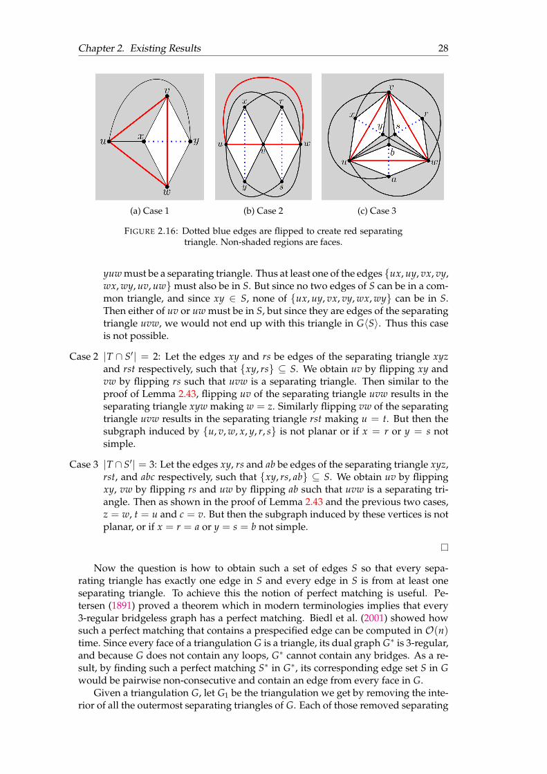
Chapter 2. Existing Results 28
(a) Case 1 (b) Case 2 (c) Case 3
FIGURE 2.16: Dotted blue edges are flipped to create red separatingtriangle. Non-shaded regions are faces.
yuw must be a separating triangle. Thus at least one of the edges ux, uy, vx, vy,wx, wy, uv, uwmust also be in S. But since no two edges of S can be in a com-mon triangle, and since xy ∈ S, none of ux, uy, vx, vy, wx, wy can be in S.Then either of uv or uw must be in S, but since they are edges of the separatingtriangle uvw, we would not end up with this triangle in G〈S〉. Thus this caseis not possible.
Case 2 |T ∩ S′| = 2: Let the edges xy and rs be edges of the separating triangle xyzand rst respectively, such that xy, rs ⊆ S. We obtain uv by flipping xy andvw by flipping rs such that uvw is a separating triangle. Then similar to theproof of Lemma 2.43, flipping uv of the separating triangle uvw results in theseparating triangle xyw making w = z. Similarly flipping vw of the separatingtriangle uvw results in the separating triangle rst making u = t. But then thesubgraph induced by u, v, w, x, y, r, s is not planar or if x = r or y = s notsimple.
Case 3 |T ∩ S′| = 3: Let the edges xy, rs and ab be edges of the separating triangle xyz,rst, and abc respectively, such that xy, rs, ab ⊆ S. We obtain uv by flippingxy, vw by flipping rs and uw by flipping ab such that uvw is a separating tri-angle. Then as shown in the proof of Lemma 2.43 and the previous two cases,z = w, t = u and c = v. But then the subgraph induced by these vertices is notplanar, or if x = r = a or y = s = b not simple.
Now the question is how to obtain such a set of edges S so that every sepa-rating triangle has exactly one edge in S and every edge in S is from at least oneseparating triangle. To achieve this the notion of perfect matching is useful. Pe-tersen (1891) proved a theorem which in modern terminologies implies that every3-regular bridgeless graph has a perfect matching. Biedl et al. (2001) showed howsuch a perfect matching that contains a prespecified edge can be computed in O(n)time. Since every face of a triangulation G is a triangle, its dual graph G∗ is 3-regular,and because G does not contain any loops, G∗ cannot contain any bridges. As a re-sult, by finding such a perfect matching S∗ in G∗, its corresponding edge set S in Gwould be pairwise non-consecutive and contain an edge from every face in G.
Given a triangulation G, let G1 be the triangulation we get by removing the inte-rior of all the outermost separating triangles of G. Each of those removed separating
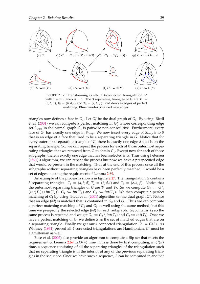
Chapter 2. Existing Results 29
FIGURE 2.17: Transforming G into a 4-connected triangulation G′
with 1 simultaneous flip. The 3 separating triangles of G are T1 =(a, b, d), T2 = (b, d, i) and T3 = (e, h, f ). Red denotes edges of perfect
matching. Blue denotes obtained new edges.
triangles now defines a face in G1. Let G∗1 be the dual graph of G1. By using Biedlet al. (2001) we can compute a perfect matching in G∗1 whose corresponding edgeset Stemp in the primal graph G1 is pairwise non-consecutive. Furthermore, everyface of G1 has exactly one edge in Stemp. We now insert every edge of Stemp into Sthat is an edge of a face that used to be a separating triangle in G. Notice that forevery outermost separating triangle of G, there is exactly one edge S that is on theseparating triangle. So, we can repeat the process for each of those outermost sepa-rating triangles that we removed from G to obtain G1. Except now for each of thosesubgraphs, there is exactly one edge that has been selected in S. Thus using Petersen(1891)’s algorithm, we can repeat the process but now we have a prespecified edgethat would be present in the matching. Thus at the end of this process once all thesubgraphs without separating triangles have been perfectly matched, S would be aset of edges meeting the requirement of Lemma 2.69.
An example of the process is shown in figure 2.17. The triangulation G contains3 separating triangles—T1 = (a, b, d), T2 = (b, d, i) and T3 = (e, h, f ). Notice thatthe outermost separating triangles of G are T1 and T2. So we compute G1 := G \(int(T1) ∪ int(T2)), G2 := int(T1) and G3 := int(T2). We then compute a perfectmatching of G1 by using Biedl et al. (2001) algorithm on the dual graph G∗1 . Noticethat an edge (bd) is matched that is contained in G2 and G3. Thus we can computea perfect matching matching of G2 and G3 as well using the same method, but thistime we prespecify the selected edge (bd) for each subgraph. G3 contains T3 so thesame process is repeated and we get G4 := G3 \ int(T3) and G5 := int(T3). Once wehave a perfect matching of G, we define S as the set of matched edges that are ona separating triangle. Finally we get our 4-connected triangulation G′ := G〈S〉. AsWhitney (1931) proved all 4 connected triangulations are Hamiltonian, G′ must beHamiltonian as well.
Bose et al. (2007) also provide an algorithm to compute a flip set that meets therequirement of Lemma 2.69 in O(n) time. This is done by first computing, in O(n)time, a sequence consisting of all the separating triangles of the triangulation suchthat no separating triangle is in the interior of any of the previous separating trian-gles in the sequence. Once we have such a sequence, S can be computed in another

Chapter 2. Existing Results 30
O(n) time. The details for this algorithm is not explained in this thesis as we do notmake any improvement in the process of creating Hamiltonian triangulation.
2.4.6 GH → Gδ: Introducing the First Dominant Vertex
Given a Hamiltonian triangulation GH with a Hamiltonian cycle H, using Lemma2.67, GH can be transformed into another triangulation G′H, where the cycle H ispreserved and the diameter of the dual tree of the subgraph G′HH is at mostc2 log n. This requires no more than c2 log n simultaneous flips. Then a vertex vin G′H is selected such that v is not incident to any external chord of cycle H. By us-ing Lemma 2.65 with no more than another c2 log n simultaneous flips we transformG′H into Gδ where the cycle H is preserved and v is a dominant vertex in GδH.Thus by no more than 2c2 log n simultaneous flips the first dominant vertex can beintroduced in a Hamiltonian triangulation.
2.4.7 Gδ → ∆n: Introducing the Second Dominant Vertex
Once we have a triangulation Gδ of order n with a dominant vertex v, notice thatG := Gδ \ v has n− 1 vertices such that all the vertices are sharing a face. Thus Gis a maximal outerplane graph. We take an embedding of G such that the outerfaceof G is in the exterior of its maximal cycle. Since v is not a part of this maximalouterplane subgraph, the edges incident to v in the original graph cannot block anyinternal chords of this maximal outerplane graph. Thus by using the next lemma,we introduce the second dominant vertex in the triangulation using another 2c1 log nsimultaneous flips completing its transformation into ∆n.
Lemma 2.70 (Bose et al. (2007) Lemma 4.5). For every maximal outerplane graph G onn vertices and for every vertex v of G, there is a sequence of 2c1 log n simultaneous flipsto transform G into a maximal outerplane graph in which v is dominant. [c1 = 2
log 65≈
7.6 log n]
Proof. The proof of this lemma proceeds in two parts. Using Lemma 2.68 we reducethe diameter of the dual tree to c1 log n with at most c1 log n simultaneous flips. Thenusing Lemma 2.65 a dominant vertex is introduced with at most a further c1 log n si-multaneous flips. Thus the total number of simultaneous flips required to transformG into Dn is 2c1 log n.
2.4.8 ∆n → G2: Do the Reverse to Transform ∆n to Target Triangulation
In Section 2.4.5, 2.4.6 and 2.4.7 we described how to transfrom any triangulationto a canonical triangulation. As explained in Definition 2.46, a simultaneous flipis an inversible operation. Thus once we know the sequence of simultaneous flipsS = (S1, S2, S3, . . . , Sk) required to transform G2 → ∆n, we can follow the sequenceof simultaneous flips S−1 = (S−1
k , S−1k−1, S−1
k−2, . . . , S−11 ) on ∆n where for all 1 ≤ k ≤ i,
S−1k is the inverse flip set of Sk—which is simply the set of new edges obtained by
flipping Sk.Since |S−1| = |S|, to complete the transformation we need the same number of
simultaneous flips as we need to transform G2 into ∆n. Thus we need at most 1simultaneous flip to introduce Hamiltonicity, 2c2 log n simultaneous flips to intro-duce the first dominant vertex, and another 2c1 log n simultaneous flips to introducethe second dominant vertex— requiring a total of 1 + 2(c1 + c2) log n simultaneousflips.
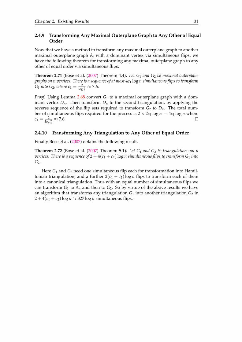
Chapter 2. Existing Results 31
2.4.9 Transforming Any Maximal Outerplane Graph to Any Other of EqualOrder
Now that we have a method to transform any maximal outerplane graph to anothermaximal outerplane graph δn with a dominant vertex via simultaneous flips, wehave the following theorem for transforming any maximal outerplane graph to anyother of equal order via simultaneous flips.
Theorem 2.71 (Bose et al. (2007) Theorem 4.4). Let G1 and G2 be maximal outerplanegraphs on n vertices. There is a sequence of at most 4c1 log n simultaneous flips to transformG1 into G2, where c1 = 2
log 65≈ 7.6.
Proof. Using Lemma 2.68 convert G1 to a maximal outerplane graph with a dom-inant vertex Dn. Then transform Dn to the second triangulation, by applying thereverse sequence of the flip sets required to transform G2 to Dn. The total num-ber of simultaneous flips required for the process is 2× 2c1 log n = 4c1 log n wherec1 = 2
log 65≈ 7.6.
2.4.10 Transforming Any Triangulation to Any Other of Equal Order
Finally Bose et al. (2007) obtains the following result.
Theorem 2.72 (Bose et al. (2007) Theorem 5.1). Let G1 and G2 be triangulations on nvertices. There is a sequence of 2 + 4(c1 + c2) log n simultaneous flips to transform G1 intoG2.
Here G1 and G2 need one simultaneous flip each for transformation into Hamil-tonian triangulation, and a further 2(c1 + c2) log n flips to transform each of theminto a canonical triangulation. Thus with an equal number of simultaneous flips wecan transform G1 to ∆n and then to G2. So by virtue of the above results we havean algorithm that transforms any triangulation G1 into another triangulation G2 in2 + 4(c1 + c2) log n ≈ 327 log n simultaneous flips.
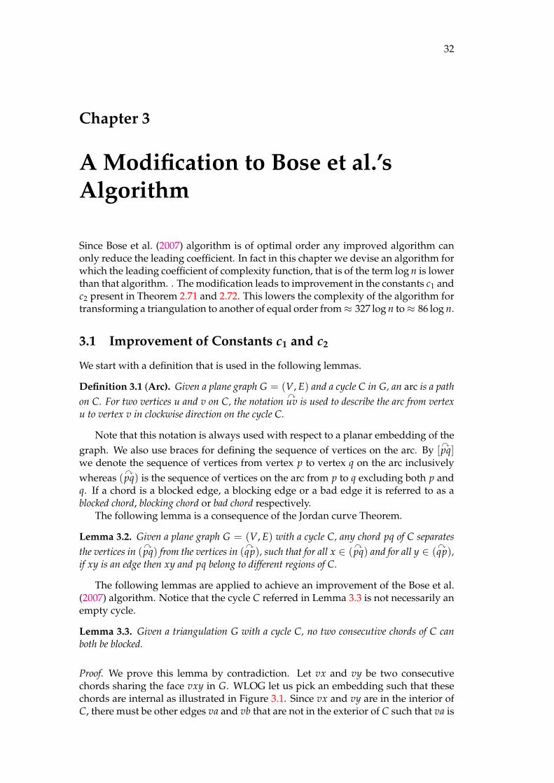
32
Chapter 3
A Modification to Bose et al.’sAlgorithm
Since Bose et al. (2007) algorithm is of optimal order any improved algorithm canonly reduce the leading coefficient. In fact in this chapter we devise an algorithm forwhich the leading coefficient of complexity function, that is of the term log n is lowerthan that algorithm. . The modification leads to improvement in the constants c1 andc2 present in Theorem 2.71 and 2.72. This lowers the complexity of the algorithm fortransforming a triangulation to another of equal order from≈ 327 log n to≈ 86 log n.
3.1 Improvement of Constants c1 and c2
We start with a definition that is used in the following lemmas.
Definition 3.1 (Arc). Given a plane graph G = (V, E) and a cycle C in G, an arc is a pathon C. For two vertices u and v on C, the notation
yuv is used to describe the arc from vertex
u to vertex v in clockwise direction on the cycle C.
Note that this notation is always used with respect to a planar embedding of thegraph. We also use braces for defining the sequence of vertices on the arc. By [
ypq]
we denote the sequence of vertices from vertex p to vertex q on the arc inclusivelywhereas (
ypq) is the sequence of vertices on the arc from p to q excluding both p and
q. If a chord is a blocked edge, a blocking edge or a bad edge it is referred to as ablocked chord, blocking chord or bad chord respectively.
The following lemma is a consequence of the Jordan curve Theorem.
Lemma 3.2. Given a plane graph G = (V, E) with a cycle C, any chord pq of C separatesthe vertices in (
ypq) from the vertices in (
yqp), such that for all x ∈ (
ypq) and for all y ∈ (
yqp),
if xy is an edge then xy and pq belong to different regions of C.
The following lemmas are applied to achieve an improvement of the Bose et al.(2007) algorithm. Notice that the cycle C referred in Lemma 3.3 is not necessarily anempty cycle.
Lemma 3.3. Given a triangulation G with a cycle C, no two consecutive chords of C canboth be blocked.
Proof. We prove this lemma by contradiction. Let vx and vy be two consecutivechords sharing the face vxy in G. WLOG let us pick an embedding such that thesechords are internal as illustrated in Figure 3.1. Since vx and vy are in the interior ofC, there must be other edges va and vb that are not in the exterior of C such that va is
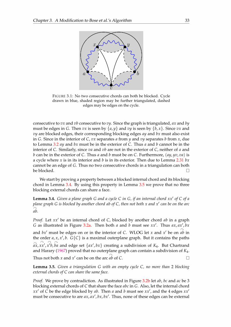
Chapter 3. A Modification to Bose et al.’s Algorithm 33
FIGURE 3.1: No two consecutive chords can both be blocked. Cycledrawn in blue, shaded region may be further triangulated, dashed
edges may be edges on the cycle.
consecutive to vx and vb consecutive to vy. Since the graph is triangulated, ax and bymust be edges in G. Then vx is seen by a, y and vy is seen by b, x. Since vx andvy are blocked edges, their corresponding blocking edges ay and bx must also existin G. Since in the interior of C, vx separates a from y and vy separates b from x, dueto Lemma 3.2 ay and bx must be in the exterior of C. Thus a and b cannot be in theinterior of C. Similarly, since va and vb are not in the exterior of C, neither of a andb can be in the exterior of C. Thus a and b must be on C. Furthermore, (ay, yv, va) isa cycle where x is in its interior and b is in its exterior. Then due to Lemma 2.31 bxcannot be an edge of G. Thus no two consecutive chords in a triangulation can bothbe blocked.
We start by proving a property between a blocked internal chord and its blockingchord in Lemma 3.4. By using this property in Lemma 3.5 we prove that no threeblocking external chords can share a face.
Lemma 3.4. Given a plane graph G and a cycle C in G, if an internal chord xx′ of C of aplane graph G is blocked by another chord ab of C, then not both x and x′ can be on the arcyab.
Proof. Let xx′ be an internal chord of C, blocked by another chord ab in a graphG as illustrated in Figure 3.2a. Then both a and b must see xx′. Thus ax, ax′, bx
and bx′ must be edges on or in the interior of C. WLOG let x and x′ be onyab in
the order a, x, x′, b. GC is a maximal outerplane graph. But it contains the pathsyax,
yxx′,
yx′b,
yba and edge set ax′, bx creating a subdivision of K4. But Chartrand
and Harary (1967) proved that no outerplane graph can contain a subdivision of K4.
Thus not both x and x′ can be on the arcyab of C.
Lemma 3.5. Given a triangulation G with an empty cycle C, no more than 2 blockingexternal chords of C can share the same face.
Proof. We prove by contradiction. As illustrated in Figure 3.2b let ab, bc and ac be 3blocking external chords of C that share the face abc in G. Also, let the internal chordxx′ of C be the edge blocked by ab. Then a and b must see xx′, and the 4 edges xx′
must be consecutive to are ax, ax′, bx, bx′. Thus, none of these edges can be external
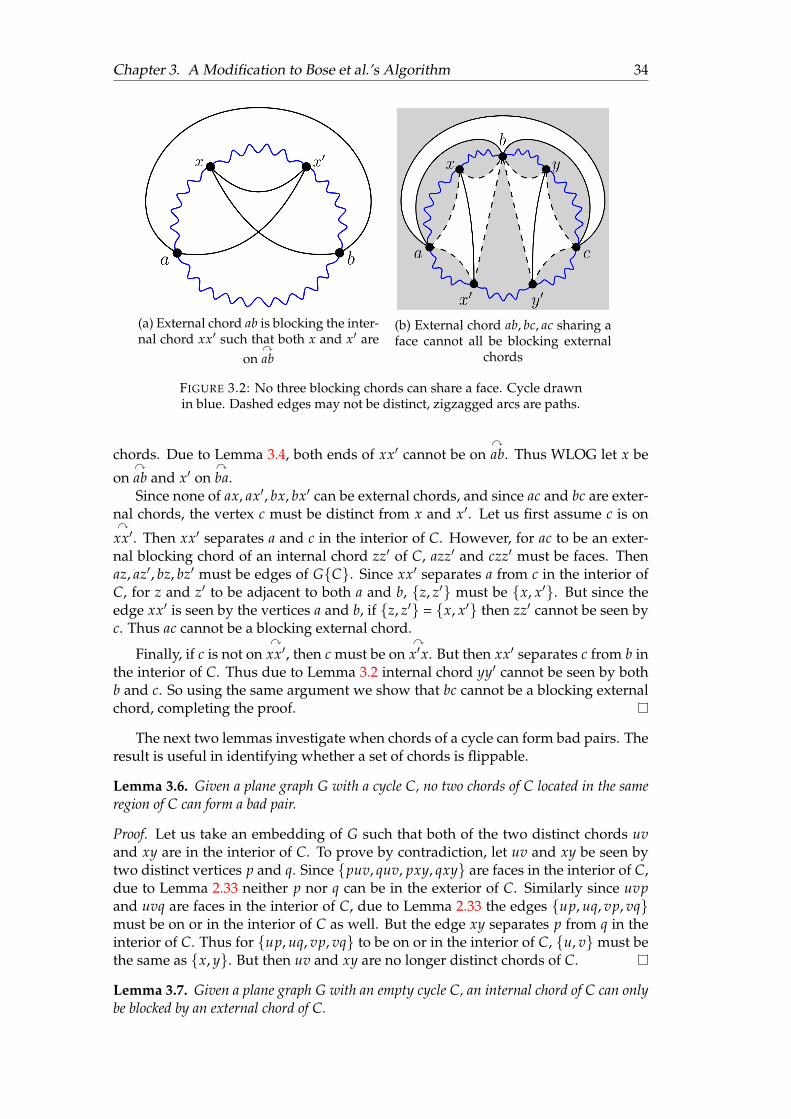
Chapter 3. A Modification to Bose et al.’s Algorithm 34
(a) External chord ab is blocking the inter-nal chord xx′ such that both x and x′ are
onyab
(b) External chord ab, bc, ac sharing aface cannot all be blocking external
chords
FIGURE 3.2: No three blocking chords can share a face. Cycle drawnin blue. Dashed edges may not be distinct, zigzagged arcs are paths.
chords. Due to Lemma 3.4, both ends of xx′ cannot be onyab. Thus WLOG let x be
onyab and x′ on
yba.
Since none of ax, ax′, bx, bx′ can be external chords, and since ac and bc are exter-nal chords, the vertex c must be distinct from x and x′. Let us first assume c is ony
xx′. Then xx′ separates a and c in the interior of C. However, for ac to be an exter-nal blocking chord of an internal chord zz′ of C, azz′ and czz′ must be faces. Thenaz, az′, bz, bz′ must be edges of GC. Since xx′ separates a from c in the interior ofC, for z and z′ to be adjacent to both a and b, z, z′ must be x, x′. But since theedge xx′ is seen by the vertices a and b, if z, z′ = x, x′ then zz′ cannot be seen byc. Thus ac cannot be a blocking external chord.
Finally, if c is not ony
xx′, then c must be ony
x′x. But then xx′ separates c from b inthe interior of C. Thus due to Lemma 3.2 internal chord yy′ cannot be seen by bothb and c. So using the same argument we show that bc cannot be a blocking externalchord, completing the proof.
The next two lemmas investigate when chords of a cycle can form bad pairs. Theresult is useful in identifying whether a set of chords is flippable.
Lemma 3.6. Given a plane graph G with a cycle C, no two chords of C located in the sameregion of C can form a bad pair.
Proof. Let us take an embedding of G such that both of the two distinct chords uvand xy are in the interior of C. To prove by contradiction, let uv and xy be seen bytwo distinct vertices p and q. Since puv, quv, pxy, qxy are faces in the interior of C,due to Lemma 2.33 neither p nor q can be in the exterior of C. Similarly since uvpand uvq are faces in the interior of C, due to Lemma 2.33 the edges up, uq, vp, vqmust be on or in the interior of C as well. But the edge xy separates p from q in theinterior of C. Thus for up, uq, vp, vq to be on or in the interior of C, u, vmust bethe same as x, y. But then uv and xy are no longer distinct chords of C.
Lemma 3.7. Given a plane graph G with an empty cycle C, an internal chord of C can onlybe blocked by an external chord of C.

Chapter 3. A Modification to Bose et al.’s Algorithm 35
Proof. Let uv be an internal chord of C, blocked by another edge xy. Then the edgeuv must be seen by the vertices x and y—making xuv and yuv faces in the interiorof C. Since uv is in the internal region of C, due to Lemma 2.33 for xuv and yuv tobe faces neither x nor y can be in the exterior of C. Thus x and y must be vertices inGC. However, the blocking edge xy cannot be in GC because then the subgraphof GC induced by the vertices u, v, x, y would create a K4. But Chartrand andHarary (1967) proved that no maximal outerplane graph can contain K4. Thus xymust be an external chord of C not present in GC.
Lemma 3.8. Given a triangulation G with an empty cycle C, any set S of blocking non-consecutive external chords of C can be simultaneously flipped.
Proof. Since the edges in S are blocking, due to Lemma 2.51 they are (individually)flippable. Since these edges are in the same region of C, Lemma 3.6 asserts thatno two of these edges can form a bad pair. Finally, since these edges are pairwisenon-consecutive, due to Lemma 2.50 S must be simultaneously flippable.
For the next lemma the notion of forest and unary tree is useful.
Definition 3.9 (Forest). A graph G = (V, E) is a forest if there is at most one unique pathbetween every pair of its vertices.
Definition 3.10 (Unary Tree). A unary tree is a tree no vertex of which has degree morethan 2.
Notice that a unary tree is equivalent to a path.
Lemma 3.11. Let G be a triangulation with an empty cycle C, with a set S of blockingexternal chords of C. Then at least half of the chords in S can be simultaneously flipped.
Proof. Let G∗ be the dual graph of G. Since the smallest cycle that can have chords ina graph is a quadrilateral with 4 vertices, for the proof we assume that the numberof vertices in C and hence G is at least 4. Since the dual graph of any triangulationon > 3 vertices is simple, the dual graph G∗ = (V∗, E∗) of G must also be simple.Let S∗ be the set of corresponding edges of S in G∗. Define G∗
′= (V∗, S∗). Notice
that only the dual edge of every edge in S is still present in G∗′. Thus two edges
are consecutive in G and are both in S if and only if their corresponding edges arepresent and are incident to a common vertex in G∗
′.
Let uv ∈ S. Then yuv ∪ uv creates a cycle Cuv. Since none of the edges of Care in S, uv must be the only edge of Cuv which is in S. Then the only edge in G∗
′
that connects any vertex corresponding to a face in the interior of Cuv to anothervertex corresponding to another face in the exterior of Cuv must be u∗v∗. Thus thecorresponding dual edge of every external blocking chord in S is a bridge in G∗
′—
making each edge of G∗′
a bridge. Then G∗′
must be a forest. Due to Lemma 3.5 nomore than 2 blocking chords can share a face and thus no vertex in G∗ can have adegree more than 2—making G∗
′a forest of unary trees.
Let there be i unary trees in G∗′
with the k-th tree containing pk edges. Sincethere is a bijection between the edges in G∗
′and S, ∑i
k=1 pk = |S|. Every unary treeis a path where, by choosing every other edge starting from the first edge in thesequence of a path of length p, a maximum matching of dp/2e edges can be foundin the path. Aggregating the maximum matching of all unary trees of the forest G∗
′
we can select a matching M∗ of size:⌈ p1
2
⌉+⌈ p2
2
⌉+⌈ p3
2
⌉+ · · ·+
⌈ pi
2
⌉≥ d(p1 + p2 + p3 + · · ·+ pi)/2e = d|S|/2e

Chapter 3. A Modification to Bose et al.’s Algorithm 36
Let the corresponding edges of M∗ in the primal graph be M. Because M∗ is a match-ing, the edges of M must be non-consecutive. Finally, all the chords in M are externalchords of C and thus due to Lemma 3.8, M must be simultaneously flippable.
The next lemma explains the recurrence relation that is found when we recur-sively obtain smaller maximal outerplane subgraphs with a fraction of the verticesof the original graph, while having its dual tree’s diameter a constant amount lessthan the previous ones. Notice that a key factor of this process is that all the pro-duced ears in each iteration is preserved in the successive iterations. This ensuresthat constant difference between the dual tree diameter between the maximal outer-plane graphs produced on each iteration is preserved in the subsequent iterations.
Lemma 3.12. Let G0 be a plane graph with an empty n-cycle C0. If there is a recursiveprocess with a constant 0 < γ < 1 with the following properties
1. Each iteration consists of k1 simultaneous flips.
2. The i-th iteration generates a graph Gi preserving all empty cycles Cj for 0 ≤ j < iand introduces another empty cycle Ci such that
(a) The cycle Ci is in the interior of the cycle Ci−1 in Gi.
(b) Length of Ci in Gi is at most (1− γ) times the length of Ci−1.
(c) The diameter of the dual tree of GiCi is exactly k2 less than the diameter of thedual tree GiCi−1
3. On the final iteration f the recursion creates a 3-cycle C f in G f .
Then the process consists of no more than k1 log nlog 1
1−γ
simultaneous flips, and the diameter of the
dual tree of G f C0 is at most k2 log nlog 1
1−γ
.
Proof. The length of the cycle reduces at least by a fraction of (1−γ) in each iteration.So after f iterations, the cycle is at most of length (1− γ) f . Thus for the final cycleto have a length no more than 3, the length of the final cycle C f :
(1− γ) f n ≤ 3 =⇒ f log(1− γ) ≤ log(3n)
=⇒ f ≥ log 3− log nlog (1− γ)
≥ − log nlog (1− γ)
=log n
log 1(1−γ)
Then the total number of simultaneous flips required is k1 × f = k1 log nlog 1
(1−γ)
. More-
over, notice that on each iteration i, all the previously generated empty cyclesC0, C1, . . . , Ci−1 are preserved. This ensures that the region interior to C0 and ex-terior to Ci (all generated ears) is preserved during i-ith and each subsequent itera-tions. Hence, the dual tree of GiCi is a subtree of the dual tree of GiCi−1 withdiameter exactly k2 less. Thus the diameter of the dual tree of G f C0 is k2 times thenumber of iterations plus the diameter of the dual tree of G f C f . The diameter ofthe dual tree of a maximal outerplane graph on 3 vertices is 0, making the diameterof the dual tree of G f C0 to be at most k2 log n
log 1(1−γ)
.
The next proof is done in the same spirit as Lemma 2.68. It formulates a processto transform a maximal outerplane graph into one whose diameter of the dual treeis logarithmic to its order.

Chapter 3. A Modification to Bose et al.’s Algorithm 37
FIGURE 3.3: Vertices of I5 (v) must have 2 non-consecutive chords.Empty cycle drawn in blue, shaded region may be further triangu-
lated, dashed edges may be edges on the cycle.
Theorem 3.13. Let G be a maximal outerplane graph on n vertices. Then G can be trans-formed by a sequence of at most c1 log n simultaneous flips into a maximal outerplane graphX such that the diameter of its dual tree X∗ is at most c1 log n, where c1 = 2
log 97≈ 5.51.
During the process the edges of the maximal cycle of G is preserved.
Proof. The proof here is in the same spirit as in Bose et al. (2007). We proceed byinduction on n. The induction hypothesis is true for the base case n = 3 as thediameter of a triangle’s dual tree is 0. Let G be a maximal outerplane graph on nvertices. Then using Equation 2.1 of Theorem 2.66, G has an independent set ofvertices I of degree no more than 5, where |I| ≥ 2
9 n. Since every vertex of a maximalouterplane graph is on a cycle, the degree of such vertices is not less than 2. Let ford ∈ 2, 3, 4, 5, Id be the set of vertices of I having degree exactly d.
As illustrated in Figure 3.3, let v be a vertex of I5 in G = (V, E), consisting of thethree internal chords vx, vy and vz arranged clockwise from the vertex v. We call vxand vz corner chords, and vy the middle chord. Since the interior of G is triangu-lated, xy and yz must be edges of G. Then vy separates x from z in the interior of G.Then vx and vz can both be seen by y. Let the other vertex that can see vx and vz be pand q respectively. Then p and q must be distinct from v and y. Then px, pv, qx, qvmust be edges of G. Then p and x cannot be separated by vy. Similarly, q and z is notseparated by vy. Then vy must separate x, p from z, q. Then due to Lemma 3.2x, p, z, q must be distinct vertices and hence (v, p, x), (v, y, x), (v, y, z), (v, z, q) dis-tinct faces as well where the first two have xv in common and the last two have vz incommon. Then the two corner chords of v (xv and vz) cannot share a common faceand thus they must be non-consecutive.
Let S be the set of edges that shall be flipped on the first simultaneous flip. Forevery vertex v ∈ I3 ∪ I4 add one internal chord incident to v in S. For each vertexv ∈ I5, add the 2 corner chords of v in S.
To prove non-consecutivity in S, assume on the contrary that xu, xv ∈ S areconsecutive. If x ∈ I5, xu and xv must be corner chords of x and hence they cannotbe consecutive to each other. x cannot be a member of I3 ∪ I4 either since only oneedge from each vertex of those sets has been included in S. Thus x 6∈ I. So u, v ∈I3 ∪ I4 ∪ I5. Since G is triangulated, for xu and xv to be consecutive, uv must bean edge. But that contradicts u and v being members of the independent set I, andtherefore cannot be adjacent. Thus the edges in S must be pairwise non-consecutive.
Chapter 3. A Modification to Bose et al.’s Algorithm 38
Let S∗ be the corresponding edges of S in the dual tree G∗ of G. Then S∗ must forma matching in G∗ and due to Lemma 2.63, S must be simultaneously flippable in G.
Let G′ = G〈S〉. Let x be a vertex of I and xy be an edge in S that when flippedproduced uv in G′. Then both u and v must be adjacent to x in G, and hence neither unor v can be in I. Thus no newly introduced edge in G′ can be incident to any vertexin I. Thus the set of vertices I must be independent in G′ as well. Furthermore, sinceflipping S reduced the degree of vertices in I3 ∪ I4 by one and vertices in I5 by two,in G′ every vertex v ∈ I2 ∪ I3 has a degree of 2, and every vertex v ∈ I4 ∪ I5 has adegree of 3. Since I4, I5 ⊆ I and I is still an independent set in G′, I4 ∪ I5 must be anindependent set of G′. Let S′ be the set of internal edges of G′ incident to verticesin I4 ∪ I5. Thus |S′| = |I4|+ |I5|, and by the same argument used for S, S′ must besimultaneously flippable in G′.
Let G′′ = G〈S′〉. Every vertex v ∈ I has degree 2 in G′′. Thus G has been trans-formed by two simultaneous flips into a maximal outerplane graph G′′ containingat least 2
9 n vertices of degree 2. Let v be a vertex with degree 2 in G′′. Then v has nointernal chords in G′′. Let the two vertices consecutive to v on the maximal cycle beu and w. Because every face in the interior of G′′ is a triangle, uw must be an edge inG′′ creating an ear (u, v, w) in G′′. Furthermore, because v ∈ I, u, w 6∈ I. Let C be themaximal cycle of G′′. We define a new cycle C′ consisting of vertices of C of degree> 2 in G′′C. Notice that we are only removing all the ears of G′′C to define themaximal outerplane graph G′′′ := G′′C′. Since every ear of G′′′ corresponds to aunique leaf of the dual tree of G′′′, the diameter of this dual tree must be exactly 2less than the diameter of the dual tree of G′′C.
Finally notice that every edge of G′′ that is not present in G′′′ is incident to avertex in I. Since G′′′ contains no vertex in I, none of these edges can be chords ofthe maximal cycle of G′′′. Hence, due to Lemma 3.7 they cannot block any internalchord of G′′′ or any other successive subgraphs obtained by repeating the process.Hence we can repeat the process until we obtain a maximal outerplane graph Xwhere the final cycle C f is a triangle. Notice that in each successive iterations, wedo not flip any edges on or in the exterior of the newly introduced maximal out-erplane subgraph, ensuring that the all the previously introduced maximal cycles(and ears) continue to be present. Thus the diameter of the dual tree of each maxi-mal outerplane subgraph stays exactly 2 less than the dual tree of the one generatedpreviously. Thus Lemma 3.12 applies on this recursive process where k1 = k2 = 2and λ = 2/9. As a result with 2 log n
log 1(1− 2
9 )
= 2 log nlog 9
7simultaneous flips we can transform
G into another maximal outerplane graph X whose diameter of the dual tree is atmost 2 log n
log 97
, making c1 = 2log 9
7≈ 5.51.
Lemma 3.14. Let G be a triangulation and C be an empty cycle of G with n vertices. (Gmay have more than n vertices.) Then G can be transformed by a sequence of at most c2 log nsimultaneous flips into a triangulation X in which C is an empty cycle and the diameter ofthe dual tree of XC is at most c2 log n. During the process no edge of H is flipped. Herec2 = 2/ log 12
11 ≈ 15.93.
Proof. By Theorem 2.66 the maximal outerplane subgraph GC has an indepen-dent set I of at least n
6 vertices such that ∀v ∈ I | degGC(v) ≤ 4. Let Id be theset of vertices v ∈ I with degGC(v) = d. Since all the vertices are on the cycleC, degGC(v) ≥ 2. Since every vertex in I4 has 2 internal chords of C, by virtue ofLemma 3.3 at least one of the chords of every vertex in I4 must be unblocked. So wemake our first simultaneous flip set S consisting of one unblocked chord incident to
Chapter 3. A Modification to Bose et al.’s Algorithm 39
each vertex v ∈ I4. All the edges in S are internal chords of the maximal outerplanegraph GC. Then none of the chords in S can be blocked. As shown in the proofof Theorem 3.13, the edges of S are pairwise non-consecutive in the maximal outer-plane graph GC. Thus in the dual tree G∗C, the corresponding edges S∗ of Sform a matching. Thus due to Lemma 2.63 S must be simultaneously flippable inGC and hence also in G. Notice that we could also insert all the unblocked chordsof I3 in S, however, it does not contribute to our analysis of the worse case as I3 couldbe empty.
Let G′ := G〈S〉. Using the same argument as in the proof of Theorem 3.13, I isstill an independent set in G′C and since we reduced the degree of all vertices inI4, ∀v ∈ I | degG′C(v) ≤ 3. For every vertex v ∈ I3, insert its remaining internalchord to S′. Let B′ be the set of all external chords that block chords of S′. UsingLemma 3.11 we can compute flippable set M′ ⊆ B′ such that |M′| ≥ 1
2 |B′|. Let S′′ bethe set consisting of all the unblocked chords of S′, and all the blocked chords of S′
whose corresponding blocking chord is in M′. Then |S′′| ≥ 12 S′. Neither S′′ nor M′
contains pairwise consecutive chords, and since edges of S′′ and M′ are in differentregions of C, edges of S′′ ∪ M′ must be pairwise non-consecutive as well. Due toLemma 3.6 neither two chords of S′′ nor two chords of M′ can be bad pairs. Further-more, a chord e of M′ cannot form bad pair with another chord e′ of S′′ because thendue to Lemma 2.52 e′ would be consecutive to a chord of S′. Thus there is no badpair in S′′ ∪ M′. Finally, every blocked chord of S′′ has its corresponding blockingchord in M′, and because every chord of M′ is blocking, due to Lemma 2.51 theycannot be blocked. Thus due to Lemma 2.50 S′′ ∪M′ is a flippable set.
Let G′′ = G′〈S′′ ∪ M′〉. As explained in the proof of Theorem 3.13, none of thenew edges of G′′C can increase the degree of a vertex in I as every new chordconnects two vertices that are consecutive to a vertex in the independent set I. Sincewe reduced at least half of the vertices in I to degree 2, there are least n/12 verticesin G′′C with a degree 2, introducing one ear in G′′C each.
The remaining part of the proof follows exactly as in the proof of Theorem 3.13but now we define a cycle C′ in G′′ removing at least n/12 vertices of degree 2 inG′′C from C. We also ensure that all of the previously introduced ears are pre-served in the successive iterations. Thus Lemma 3.12 applies on this recursive pro-cess where k1 = k2 = 2 and γ = 1/12. As a result with 2 log n
log 1(1− 1
12 )
= 2 log nlog 12
11simul-
taneous flips we can transform G into another maximal outerplane graph X whosediameter of the dual tree is at most 2 log n
log 1211
, making c2 = 2log 12
11.
So the above results lead to the following theorem.
Theorem 3.15 (In the spirit of Bose et al. (2007) Theorem 5.1). Let G1 and G2 be trian-gulations on n vertices. There is a sequence of at most 2 + 4(c1 + c2) log n ≈ 85.8 log n si-multaneous flips to transform G1 into G2, where c1 = 2
log 97≈ 5.52 and c2 = 2
log 1211≈ 15.93.
Proof. As explained in Section 2.4.5, Bose et al. (2007) proved that with 1 simulta-neous flip transform G1 into a Hamiltonian triangulation GH with a Hamiltoniancycle H. To convert GH to a canonical triangulation, first transform it into anotherHamiltonian triangulation X using Lemma 3.14 where the dual tree of XH hasa diameter of at most c2 log n. This takes at most c2 log n simultaneous flips. Thenchoose a vertex v that is not incident to any external chords of H in X. By usingLemma 2.65 with no more than another c2 log n simultaneous flips, transform X intoXδ where v is the first dominant vertex in XδH. Since v does not have any ex-ternal chords in Xδ, none of the edges flipped during Lemma 2.65 can be blocked.

Chapter 3. A Modification to Bose et al.’s Algorithm 40
Furthermore, for the two vertices u and w consecutive to v in H, uw must be an ex-ternal chord in X∆. So we define a new empty cycle C replaces the edge sequence(uv, vw) with uw from H. Now define Xop := Xδ \ v. Notice that Xop is a maximalouterplane graph with its maximal cycle being C.
By first using Theorem 3.13 and then Lemma 2.65 on the resulting graph, withno more than 2c1 log (n− 1) simultaneous flips, where c1 = 2
log 97
we can transform
Xop into a maximal outerplane graph of n− 1 vertices δn−1 with a dominant vertex.Furthermore, every edge of Xδ that is missing in Xop is incident to the vertex v,which is not present in Xop either. Thus, none of these edges are chords of C in Xδ.Therefore, due to Lemma 3.7, none of these chords can block any internal chords ofC. Thus the sequence of simultaneous flips made to transform Xop into δn−1 is alsovalid in Xδ transforming the graph into a canonical triangulation ∆n.
Now that we have transformed G1 into ∆n with no more than 1+ 2(c1 + c2) log nsimultaneous flips, using the exact same method with no more than the the samenumber of simultaneous flips we can transform G2 into ∆n. Therefore, to transformG1 into G2, first transform G1 into ∆n, and then by following the reverse sequenceof simultaneous flips transform G2 into ∆n, complete the transformation of G1 intoG2. The process requires no more than 2 + 4(c1 + c2) log n simultaneous flips tocomplete.
3.2 Optimal Degree Restriction for Independent Set to Intro-duce a Dominant Vertex in a Maximal Outerplane Graph
In this section we show what the optimal size of the independent set should be foreach iteration to introduce a dominant vertex in a maximal outerplane graph usingthe algorithm described in Theorem 2.71. We optimize our algorithm by selectingright upper bounds on the degree of vertices of the independent sets consideringthe following two points.
1. The number of ears introduced on each iteration.
2. The number of simultaneous flips required per iteration.
Once the diameter of the dual tree of the maximal outerplane graph is made loga-rithmic, by using Lemma 2.65 a dominant vertex is introduced in G with no morethan the number of simultaneous flips equaling the diameter of its dual tree.
In the following, we show that d = 5 indeed ensures the minimum upper boundfor the number of flips required for our algorithm to introduce a dominant vertex inany arbitrary maximal outerplane graph G of order n.
Due to Lemma 2.63 the chords of outerplane graphs are not blocked and do notform bad pairs. Hence to flip them simultaneously, all we have to ensure is that theyare not consecutive. For any vertex v ∈ I, with degree d, v has d− 2 internal chords.By selecting every other chord according to their cyclic order from the vertex v wecan select at least d d−2
2 e internal chords incident to v, such that they are a pairwisenon-consecutive set of edges. Flipping these chords ensures a degree reduction of vby the number of incident chords flipped. So the number β(d) of simultaneous flipssufficient to reduce any member of Id into an ear is:
β(d) =
d− 2 if 2 < d < 51 + β(b d+2
2 c) for d ≥ 5
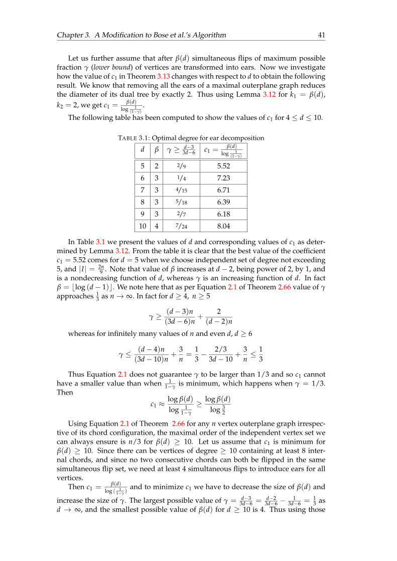
Chapter 3. A Modification to Bose et al.’s Algorithm 41
Let us further assume that after β(d) simultaneous flips of maximum possiblefraction γ (lower bound) of vertices are transformed into ears. Now we investigatehow the value of c1 in Theorem 3.13 changes with respect to d to obtain the followingresult. We know that removing all the ears of a maximal outerplane graph reducesthe diameter of its dual tree by exactly 2. Thus using Lemma 3.12 for k1 = β(d),k2 = 2, we get c1 = β(d)
log 1(1−γ)
.
The following table has been computed to show the values of c1 for 4 ≤ d ≤ 10.
TABLE 3.1: Optimal degree for ear decomposition
d β γ ≥ d−33d−6 c1 = β(d)
log 1(1−γ)
5 2 2/9 5.52
6 3 1/4 7.23
7 3 4/15 6.71
8 3 5/18 6.39
9 3 2/7 6.18
10 4 7/24 8.04
In Table 3.1 we present the values of d and corresponding values of c1 as deter-mined by Lemma 3.12. From the table it is clear that the best value of the coefficientc1 = 5.52 comes for d = 5 when we choose independent set of degree not exceeding5, and |I| = 2n
9 . Note that value of β increases at d− 2, being power of 2, by 1, andis a nondecreasing function of d, whereas γ is an increasing function of d. In factβ = blog (d− 1)c. We note here that as per Equation 2.1 of Theorem 2.66 value of γapproaches 1
3 as n→ ∞. In fact for d ≥ 4, n ≥ 5
γ ≥ (d− 3)n(3d− 6)n
+2
(d− 2)n
whereas for infinitely many values of n and even d, d ≥ 6
γ ≤ (d− 4)n(3d− 10)n
+3n=
13− 2/3
3d− 10+
3n≤ 1
3
Thus Equation 2.1 does not guarantee γ to be larger than 1/3 and so c1 cannothave a smaller value than when 1
1−γ is minimum, which happens when γ = 1/3.Then
c1 ≈log β(d)log 1
1−γ
≥ log β(d)log 3
2
Using Equation 2.1 of Theorem 2.66 for any n vertex outerplane graph irrespec-tive of its chord configuration, the maximal order of the independent vertex set wecan always ensure is n/3 for β(d) ≥ 10. Let us assume that c1 is minimum forβ(d) ≥ 10. Since there can be vertices of degree ≥ 10 containing at least 8 inter-nal chords, and since no two consecutive chords can both be flipped in the samesimultaneous flip set, we need at least 4 simultaneous flips to introduce ears for allvertices.
Then c1 = β(d)log ( 1
1−γ )and to minimize c1 we have to decrease the size of β(d) and
increase the size of γ. The largest possible value of γ = d−33d−6 = d−2
3d−6 −1
3d−6 = 13 as
d → ∞, and the smallest possible value of β(d) for d ≥ 10 is 4. Thus using those
Chapter 3. A Modification to Bose et al.’s Algorithm 42
values we get ∀d ≥ 10 | c1 ≥ 4log 3
2≈ 6.83. Note that in fact the value of c1 must be
much more since value of β(d) will also go up as d increases.Finally, we can see from Table 3.1, the optimal value of c1 for 4 ≤ d ≤ 10 is
≈ 5.52 for d = 5 which gives better result than for values of d exceeding 10. Thus c1is minimum for d = 5.
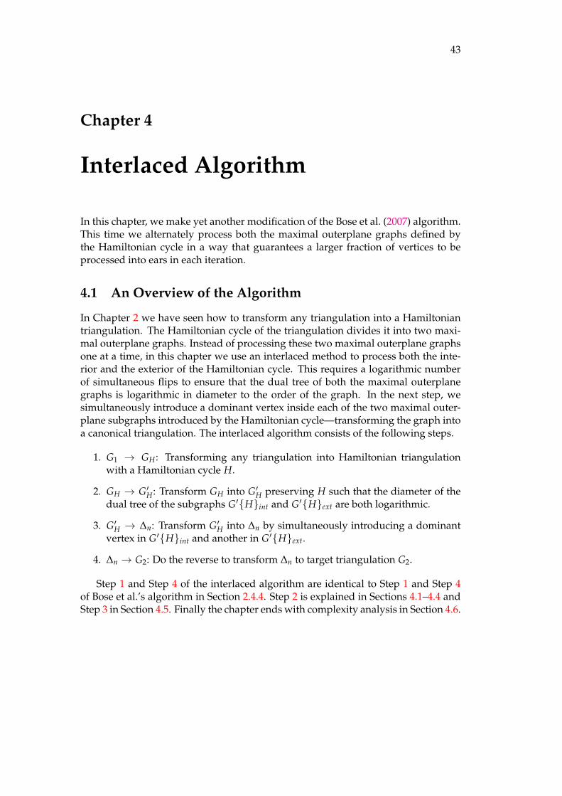
43
Chapter 4
Interlaced Algorithm
In this chapter, we make yet another modification of the Bose et al. (2007) algorithm.This time we alternately process both the maximal outerplane graphs defined bythe Hamiltonian cycle in a way that guarantees a larger fraction of vertices to beprocessed into ears in each iteration.
4.1 An Overview of the Algorithm
In Chapter 2 we have seen how to transform any triangulation into a Hamiltoniantriangulation. The Hamiltonian cycle of the triangulation divides it into two maxi-mal outerplane graphs. Instead of processing these two maximal outerplane graphsone at a time, in this chapter we use an interlaced method to process both the inte-rior and the exterior of the Hamiltonian cycle. This requires a logarithmic numberof simultaneous flips to ensure that the dual tree of both the maximal outerplanegraphs is logarithmic in diameter to the order of the graph. In the next step, wesimultaneously introduce a dominant vertex inside each of the two maximal outer-plane subgraphs introduced by the Hamiltonian cycle—transforming the graph intoa canonical triangulation. The interlaced algorithm consists of the following steps.
1. G1 → GH: Transforming any triangulation into Hamiltonian triangulationwith a Hamiltonian cycle H.
2. GH → G′H: Transform GH into G′H preserving H such that the diameter of thedual tree of the subgraphs G′Hint and G′Hext are both logarithmic.
3. G′H → ∆n: Transform G′H into ∆n by simultaneously introducing a dominantvertex in G′Hint and another in G′Hext.
4. ∆n → G2: Do the reverse to transform ∆n to target triangulation G2.
Step 1 and Step 4 of the interlaced algorithm are identical to Step 1 and Step 4of Bose et al.’s algorithm in Section 2.4.4. Step 2 is explained in Sections 4.1–4.4 andStep 3 in Section 4.5. Finally the chapter ends with complexity analysis in Section 4.6.
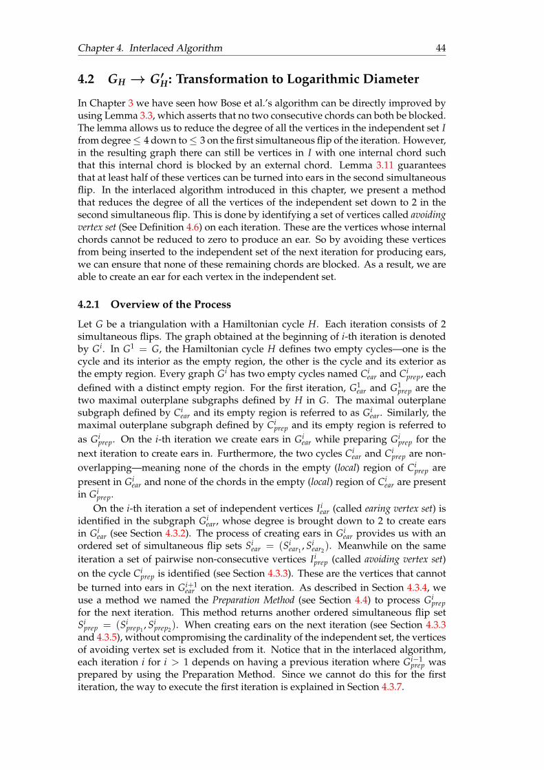
Chapter 4. Interlaced Algorithm 44
4.2 GH → G′H : Transformation to Logarithmic Diameter
In Chapter 3 we have seen how Bose et al.’s algorithm can be directly improved byusing Lemma 3.3, which asserts that no two consecutive chords can both be blocked.The lemma allows us to reduce the degree of all the vertices in the independent set Ifrom degree≤ 4 down to≤ 3 on the first simultaneous flip of the iteration. However,in the resulting graph there can still be vertices in I with one internal chord suchthat this internal chord is blocked by an external chord. Lemma 3.11 guaranteesthat at least half of these vertices can be turned into ears in the second simultaneousflip. In the interlaced algorithm introduced in this chapter, we present a methodthat reduces the degree of all the vertices of the independent set down to 2 in thesecond simultaneous flip. This is done by identifying a set of vertices called avoidingvertex set (See Definition 4.6) on each iteration. These are the vertices whose internalchords cannot be reduced to zero to produce an ear. So by avoiding these verticesfrom being inserted to the independent set of the next iteration for producing ears,we can ensure that none of these remaining chords are blocked. As a result, we areable to create an ear for each vertex in the independent set.
4.2.1 Overview of the Process
Let G be a triangulation with a Hamiltonian cycle H. Each iteration consists of 2simultaneous flips. The graph obtained at the beginning of i-th iteration is denotedby Gi. In G1 = G, the Hamiltonian cycle H defines two empty cycles—one is thecycle and its interior as the empty region, the other is the cycle and its exterior asthe empty region. Every graph Gi has two empty cycles named Ci
ear and Ciprep, each
defined with a distinct empty region. For the first iteration, G1ear and G1
prep are thetwo maximal outerplane subgraphs defined by H in G. The maximal outerplanesubgraph defined by Ci
ear and its empty region is referred to as Giear. Similarly, the
maximal outerplane subgraph defined by Ciprep and its empty region is referred to
as Giprep. On the i-th iteration we create ears in Gi
ear while preparing Giprep for the
next iteration to create ears in. Furthermore, the two cycles Ciear and Ci
prep are non-overlapping—meaning none of the chords in the empty (local) region of Ci
prep arepresent in Gi
ear and none of the chords in the empty (local) region of Ciear are present
in Giprep.
On the i-th iteration a set of independent vertices Iiear (called earing vertex set) is
identified in the subgraph Giear, whose degree is brought down to 2 to create ears
in Giear (see Section 4.3.2). The process of creating ears in Gi
ear provides us with anordered set of simultaneous flip sets Si
ear = (Siear1
, Siear2
). Meanwhile on the sameiteration a set of pairwise non-consecutive vertices Ii
prep (called avoiding vertex set)on the cycle Ci
prep is identified (see Section 4.3.3). These are the vertices that cannotbe turned into ears in Gi+1
ear on the next iteration. As described in Section 4.3.4, weuse a method we named the Preparation Method (see Section 4.4) to process Gi
prepfor the next iteration. This method returns another ordered simultaneous flip setSi
prep = (Siprep1
, Siprep2
). When creating ears on the next iteration (see Section 4.3.3and 4.3.5), without compromising the cardinality of the independent set, the verticesof avoiding vertex set is excluded from it. Notice that in the interlaced algorithm,each iteration i for i > 1 depends on having a previous iteration where Gi−1
prep wasprepared by using the Preparation Method. Since we cannot do this for the firstiteration, the way to execute the first iteration is explained in Section 4.3.7.
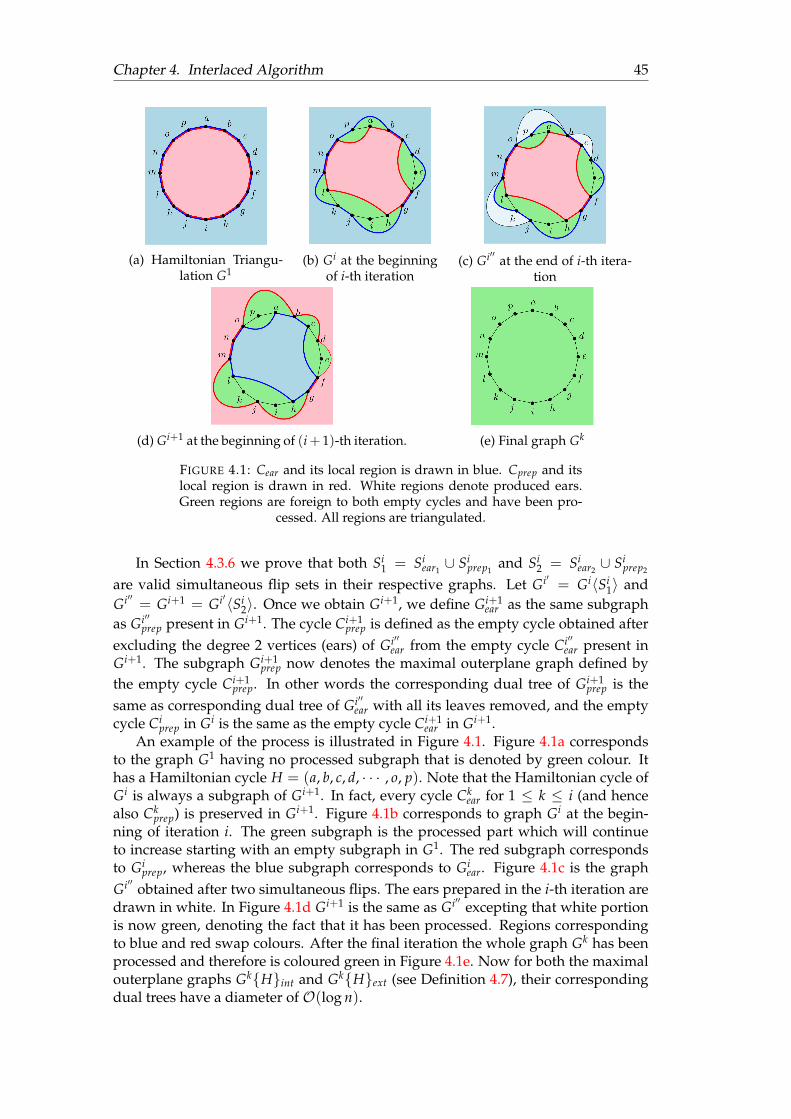
Chapter 4. Interlaced Algorithm 45
(a) Hamiltonian Triangu-lation G1
(b) Gi at the beginningof i-th iteration
(c) Gi′′ at the end of i-th itera-tion
(d) Gi+1 at the beginning of (i+ 1)-th iteration. (e) Final graph Gk
FIGURE 4.1: Cear and its local region is drawn in blue. Cprep and itslocal region is drawn in red. White regions denote produced ears.Green regions are foreign to both empty cycles and have been pro-
cessed. All regions are triangulated.
In Section 4.3.6 we prove that both Si1 = Si
ear1∪ Si
prep1and Si
2 = Siear2∪ Si
prep2
are valid simultaneous flip sets in their respective graphs. Let Gi′ = Gi〈Si1〉 and
Gi′′ = Gi+1 = Gi′〈Si2〉. Once we obtain Gi+1, we define Gi+1
ear as the same subgraphas Gi′′
prep present in Gi+1. The cycle Ci+1prep is defined as the empty cycle obtained after
excluding the degree 2 vertices (ears) of Gi′′ear from the empty cycle Ci′′
ear present inGi+1. The subgraph Gi+1
prep now denotes the maximal outerplane graph defined bythe empty cycle Ci+1
prep. In other words the corresponding dual tree of Gi+1prep is the
same as corresponding dual tree of Gi′′ear with all its leaves removed, and the empty
cycle Ciprep in Gi is the same as the empty cycle Ci+1
ear in Gi+1.An example of the process is illustrated in Figure 4.1. Figure 4.1a corresponds
to the graph G1 having no processed subgraph that is denoted by green colour. Ithas a Hamiltonian cycle H = (a, b, c, d, · · · , o, p). Note that the Hamiltonian cycle ofGi is always a subgraph of Gi+1. In fact, every cycle Ck
ear for 1 ≤ k ≤ i (and hencealso Ck
prep) is preserved in Gi+1. Figure 4.1b corresponds to graph Gi at the begin-ning of iteration i. The green subgraph is the processed part which will continueto increase starting with an empty subgraph in G1. The red subgraph correspondsto Gi
prep, whereas the blue subgraph corresponds to Giear. Figure 4.1c is the graph
Gi′′ obtained after two simultaneous flips. The ears prepared in the i-th iteration aredrawn in white. In Figure 4.1d Gi+1 is the same as Gi′′ excepting that white portionis now green, denoting the fact that it has been processed. Regions correspondingto blue and red swap colours. After the final iteration the whole graph Gk has beenprocessed and therefore is coloured green in Figure 4.1e. Now for both the maximalouterplane graphs GkHint and GkHext (see Definition 4.7), their correspondingdual trees have a diameter of O(log n).
Chapter 4. Interlaced Algorithm 46
4.2.2 Definition
For ease of exposition, we introduce the following definitions to formally definestructures forming the skeleton of our algorithm.
Definition 4.1 (Ordered Set of Flippable Sets). Given a plane graph G0 = (V, E) andan ordered set of edge sets S = (S1, S2, . . . , Sk), such that Si is simultaneously flippable inGi−1, and for 1 ≤ i ≤ k, Gi := Gi−1〈Si〉, then S is called an ordered set of flippable sets.The resulting graph obtained by sequentially flipping S in G is written as G〈S〉.
Given two ordered sets of flippable sets S1 = (S1,1, S1,2, . . . , S1,m) andS2 = (S2,1, S2,2, . . . , S2,n) where m ≤ n, we define their union as following.
S1 ∪ S2 := (S1,1 ∪ S2,1, S1,2 ∪ S2,2, . . . , S1,m ∪ S2,m, S2,m+1, S2,m+2, . . . , S2,n)
Definition 4.2 (Non-overlapping Maximal Outerplane Subgraphs). Let G be a tri-angulation with two empty cycles C1 and C2. Furthermore, let G1 and G2 be the maximalouterplane subgraphs defined by C1 and C2 along with their corresponding local regions re-spectively. If no local chord of C1 is an edge in G2 and no local chords of C2 is an edge in G1,then C1 and C2 are non-overlapping empty cycles, and G1 and G2 are non-overlappingmaximal outerplane subgraphs in G.
Note that two non-overlapping empty cycles/maximal outerplane subgraphsmay have vertices and edges of the cycles in common. In the interlaced algorithm,for any iteration i, Gi
ear and Giprep are non-overlapping maximal outerplane sub-
graphs of Gi.
Definition 4.3 (Local Chord, Foreign Chord). Given a plane graph G = (V, E) with anempty cycle C, a chord of C is a local chord if it passes through C’s local region. Otherwiseit is a foreign chord of C.
In Chapters 2 and 3 all the empty cycles we considered have their local regionslocated in the interior of the cycle. Thus in all previous lemmas, internal chords arelocal chords, and external chords are foreign chords of their respective empty cycles.Because Ci+1
ear and Ci+1prep point to different regions than Ci
ear and Ciprep respectively, for
clarity when dealing with chords of empty cycles we shall be using the terms localchord and foreign chord for the rest of this chapter.
Definition 4.4 (k-chord). Given a triangulation G = (V, E) with an empty cycle C letp0 and pk be two vertices on C connected by the chord p0 pk such that there is a path P =(p0, p1, · · · , pk) of length k on the cycle C. Then p0 pk is called a k-chord of C.
A k-chord of an n-cycle is also an (n− k)-chord.
Definition 4.5 (Avoiding Vertex). Given a triangulation G = (V, E) with an empty cycleC let pq be a foreign 2-chord of C creating a 3-cycle (p, q, r) with another vertex r of C suchthat pr and qr are edges of C. Then r is called pq’s avoiding vertex, and pq is referred to asr’s corresponding 2-chord.
Note that these vertices p, q must be non-consecutive on the cycle C, as otherwiseG is not simple.
Definition 4.6 (Avoiding Vertex Set, Iavoid). Given the setup described in Section 4.2.1,the avoiding vertex set, referred to as Ii
avoid is the set of all avoiding vertices of Ci+1ear in
Gi+1.
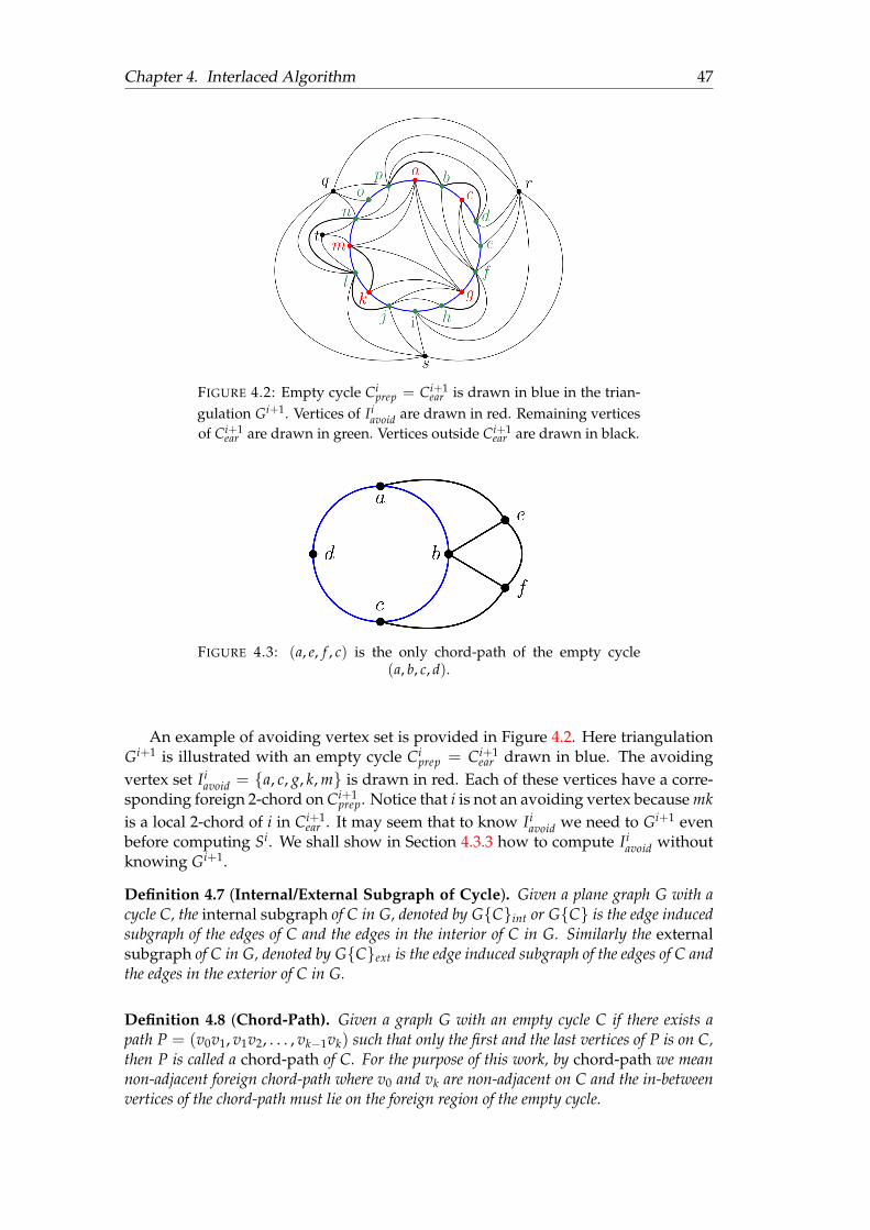
Chapter 4. Interlaced Algorithm 47
FIGURE 4.2: Empty cycle Ciprep = Ci+1
ear is drawn in blue in the trian-gulation Gi+1. Vertices of Ii
avoid are drawn in red. Remaining verticesof Ci+1
ear are drawn in green. Vertices outside Ci+1ear are drawn in black.
FIGURE 4.3: (a, e, f , c) is the only chord-path of the empty cycle(a, b, c, d).
An example of avoiding vertex set is provided in Figure 4.2. Here triangulationGi+1 is illustrated with an empty cycle Ci
prep = Ci+1ear drawn in blue. The avoiding
vertex set Iiavoid = a, c, g, k, m is drawn in red. Each of these vertices have a corre-
sponding foreign 2-chord on Ci+1prep. Notice that i is not an avoiding vertex because mk
is a local 2-chord of i in Ci+1ear . It may seem that to know Ii
avoid we need to Gi+1 evenbefore computing Si. We shall show in Section 4.3.3 how to compute Ii
avoid withoutknowing Gi+1.
Definition 4.7 (Internal/External Subgraph of Cycle). Given a plane graph G with acycle C, the internal subgraph of C in G, denoted by GCint or GC is the edge inducedsubgraph of the edges of C and the edges in the interior of C in G. Similarly the externalsubgraph of C in G, denoted by GCext is the edge induced subgraph of the edges of C andthe edges in the exterior of C in G.
Definition 4.8 (Chord-Path). Given a graph G with an empty cycle C if there exists apath P = (v0v1, v1v2, . . . , vk−1vk) such that only the first and the last vertices of P is on C,then P is called a chord-path of C. For the purpose of this work, by chord-path we meannon-adjacent foreign chord-path where v0 and vk are non-adjacent on C and the in-betweenvertices of the chord-path must lie on the foreign region of the empty cycle.

Chapter 4. Interlaced Algorithm 48
In figure 4.3 (a, e, f , c) is the only chord-path of the empty cycle C = (a, b, c, d).The path (a, e, b) is a chord-path of C because a and b are consecutive on C. The path(a, e, b, f , c) is not a chord-path of C because b is an in-between vertex of the paththat also lies on C.
Definition 4.9 (Earing Vertex, Earing Chord). Given the setup described in Section 4.2.1,on the i-th iteration, The set of earing vertices referred by Ii
ear is the set of independent ver-tices in Gi
ear whose degree is to be reduced to 2 to produce ears in Gi′′ear. Each vertex of Ii
ear iscalled an earing vertex. Any local chord of Ci
ear incident to an earing vertex of Ciear is called
an earing chord.
Definition 4.10 (Provisioning Chord). Given the setup described in Section 4.2.1, on thei-th iteration, a provisioning chord e is a local chord of the empty cycle Ci
prep that is seenby a vertex v in Ii
avoid of the cycle. So when e is flipped, the degree of v (the avoiding vertexof e) increases. If flipping e increases the degree of exactly one vertex in Ii
avoid, then e is calleda singly provisioning chord and otherwise it must be increasing the degree of two verticesof Ii
avoid and thus is called a doubly provisioning chord.1
Definition 4.11 (Neighbourhood). Given a graph G = (V, E) and a vertex v ∈ V,the neighbourhood of v (denoted by NG(v)) is the set of vertices v is connected to. Theclosed neighbourhood of v (denoted by NG[v]) is the neighbourhood of v together with v.NG[v] = NG(v) ∪ v.
Definition 4.12 (Dominating Vertex, Corner Vertex). Given a graph G = (V, E), fortwo vertices u, v ∈ V, if NG[u] ⊆ NG[v] then u is called a corner vertex of v and v is calleda dominating vertex to u.
4.3 Creating Ears in Giear
As illustrated in Figure 4.4, on the i-th iteration, let u be a vertex in Iiear with 2 local
chords e1 = uv and e2 = uw in Giear (subgraph of Gi). Let p, q be the two vertices
adjacent to u on Ciear such that uv and uw are respectively seen by p and q. To reduce
the degree of u to 2 in Giear, these two chords can be flipped in two different orders—
(e1, e2), and (e2, e1). Let e′1 be the chord obtained by flipping e1 individuallyin Gi and let e′2 be the chord obtained by flipping e2 individually in Gi. Regardlessof their order, the flipping of the second chord would produce the chord e′ = pqintroducing the ear pqu in Gi′′
ear.Notice that e′ and one of e′1 and e′2 may end up being foreign 2-chords of Gi′′
prep,and thus the order in which e1 and e2 are flipped is important as the set of avoidingvertices Ii
avoid depends upon whether Gi′′ contains e′1, e′ or e′2, e′. On the otherhand, without knowing Ii
avoid we cannot compute Siprep1
and Siprep2
. Furthermore,it may be possible that one or both of e1 and e2 are blocking provisioning chords,complicating the process of computing the provisioning chords and the blockingchords as we do not yet know the vertices of Ii
avoid, which demands knowing theorder in which the earing chords are flipped.
1While the definition of provisioning chord is accurate for the purpose of this section, a more com-plete definition is provided in Definition 4.28.
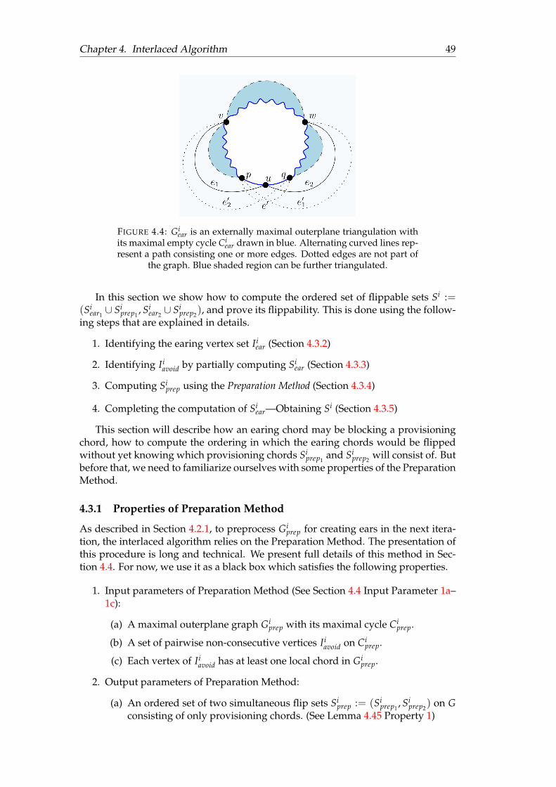
Chapter 4. Interlaced Algorithm 49
FIGURE 4.4: Giear is an externally maximal outerplane triangulation with
its maximal empty cycle Ciear drawn in blue. Alternating curved lines rep-
resent a path consisting one or more edges. Dotted edges are not part ofthe graph. Blue shaded region can be further triangulated.
In this section we show how to compute the ordered set of flippable sets Si :=(Si
ear1∪ Si
prep1, Si
ear2∪ Si
prep2), and prove its flippability. This is done using the follow-
ing steps that are explained in details.
1. Identifying the earing vertex set Iiear (Section 4.3.2)
2. Identifying Iiavoid by partially computing Si
ear (Section 4.3.3)
3. Computing Siprep using the Preparation Method (Section 4.3.4)
4. Completing the computation of Siear—Obtaining Si (Section 4.3.5)
This section will describe how an earing chord may be blocking a provisioningchord, how to compute the ordering in which the earing chords would be flippedwithout yet knowing which provisioning chords Si
prep1and Si
prep2will consist of. But
before that, we need to familiarize ourselves with some properties of the PreparationMethod.
4.3.1 Properties of Preparation Method
As described in Section 4.2.1, to preprocess Giprep for creating ears in the next itera-
tion, the interlaced algorithm relies on the Preparation Method. The presentation ofthis procedure is long and technical. We present full details of this method in Sec-tion 4.4. For now, we use it as a black box which satisfies the following properties.
1. Input parameters of Preparation Method (See Section 4.4 Input Parameter 1a–1c):
(a) A maximal outerplane graph Giprep with its maximal cycle Ci
prep.
(b) A set of pairwise non-consecutive vertices Iiavoid on Ci
prep.
(c) Each vertex of Iiavoid has at least one local chord in Gi
prep.
2. Output parameters of Preparation Method:
(a) An ordered set of two simultaneous flip sets Siprep := (Si
prep1, Si
prep2) on G
consisting of only provisioning chords. (See Lemma 4.45 Property 1)
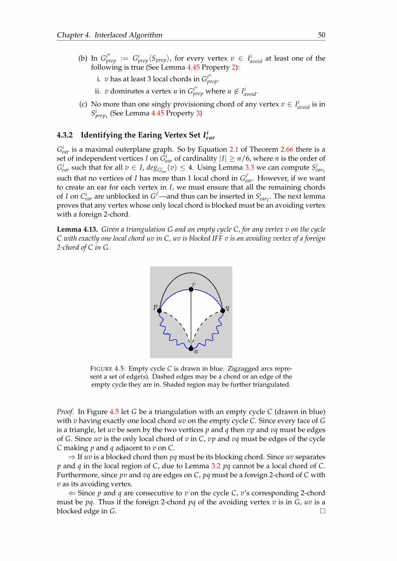
Chapter 4. Interlaced Algorithm 50
(b) In Gi′′prep := Gi
prep〈Sprep〉, for every vertex v ∈ Iiavoid at least one of the
following is true (See Lemma 4.45 Property 2):
i. v has at least 3 local chords in Gi′′prep.
ii. v dominates a vertex u in Gi′′prep where u 6∈ Ii
avoid.
(c) No more than one singly provisioning chord of any vertex v ∈ Iiavoid is in
Siprep1
(See Lemma 4.45 Property 3)
4.3.2 Identifying the Earing Vertex Set Iiear
Giear is a maximal outerplane graph. So by Equation 2.1 of Theorem 2.66 there is a
set of independent vertices I on Giear of cardinality |I| ≥ n/6, where n is the order of
Giear such that for all v ∈ I, degGi
ear(v) ≤ 4. Using Lemma 3.3 we can compute Si
ear1
such that no vertices of I has more than 1 local chord in Gi′ear. However, if we want
to create an ear for each vertex in I, we must ensure that all the remaining chordsof I on Ci
ear are unblocked in Gi′—and thus can be inserted in Siear2
. The next lemmaproves that any vertex whose only local chord is blocked must be an avoiding vertexwith a foreign 2-chord.
Lemma 4.13. Given a triangulation G and an empty cycle C, for any vertex v on the cycleC with exactly one local chord uv in C, uv is blocked IFF v is an avoiding vertex of a foreign2-chord of C in G.
FIGURE 4.5: Empty cycle C is drawn in blue. Zigzagged arcs repre-sent a set of edge(s). Dashed edges may be a chord or an edge of theempty cycle they are in. Shaded region may be further triangulated.
Proof. In Figure 4.5 let G be a triangulation with an empty cycle C (drawn in blue)with v having exactly one local chord uv on the empty cycle C. Since every face of Gis a triangle, let uv be seen by the two vertices p and q then vp and vq must be edgesof G. Since uv is the only local chord of v in C, vp and vq must be edges of the cycleC making p and q adjacent to v on C.⇒ If uv is a blocked chord then pq must be its blocking chord. Since uv separates
p and q in the local region of C, due to Lemma 3.2 pq cannot be a local chord of C.Furthermore, since pv and vq are edges on C, pq must be a foreign 2-chord of C withv as its avoiding vertex.⇐ Since p and q are consecutive to v on the cycle C, v’s corresponding 2-chord
must be pq. Thus if the foreign 2-chord pq of the avoiding vertex v is in G, uv is ablocked edge in G.
Chapter 4. Interlaced Algorithm 51
As a result of Lemma 4.13, to ensure that we can flip all the earing chords, weare interested in having an independent set of vertices where none of the verticeshave a foreign 2-chord on Ci
ear. This is where the Preparation Method explained inSection 4.4 becomes useful. For any iteration i > 1 we processed the maximal outer-plane subgraph Gi
ear in the previous iteration ensuring that Giear has the Property 2b
described in Section 4.3.1. Notice, that on the (i − 1)-th iteration, vertex set Ii−1avoid
denotes to the set of vertices each of which has a foreign 2-chord of the cycle Ciear in
Gi.We first obtain a set of independent vertices I of degree at most 4 on Gi
ear usingEquation 2.1 of Theorem 2.66 such that |I| ≥ n/6. We know that some of these ver-tices can be avoiding vertices. However, for any iteration i > 1, due to Property 2bof the Preparation Method, any vertex v in I that is an avoiding vertex would domi-nate another vertex u in Gi
ear that is not an avoiding vertex, so degGiear(u) ≤ degGi
ear(v).
Thus we can replace each vertex of I that is an avoiding vertex, with a non-avoidingvertex and call the new set Ii
ear. Now we have to ensure that Iiear is still a set of inde-
pendent vertices, and the order of Iiear is the same as the order of I. The next lemma
indeed confirms independence and the required order of Iiear.
Lemma 4.14. Given a graph G = (V, E), an independent set of vertices I ⊆ V, a vertexv ∈ I and another vertex u ∈ V such that v dominates u, then I′=(I \ v) ∪ u is anindependent vertex set of the same cardinality as I.
Proof. Since v dominates u and v ∈ I, u /∈ I. Furthermore, since every vertex u isconnected to, v is also connected to and none of the other vertices of I is connectedto v, none of the vertices in I \ v can be connected to u. Thus I′=I \ v ∪ u is anindependent set. Because we get I′ by replacing one vertex of I with another vertex,|I′| = |I|.
As we can see in Lemma 4.14, every time we replace an avoiding vertex v fromour independent set with another vertex u that v dominates, the new set is still anindependent set with the same cardinality. Thus repeating the process until thereare no avoiding vertices in the set will produce our preferred independent set Ii
earwith |Ii
ear| ≥ n/6, where n is the order of Giear such that no vertex of Ii
ear has a foreign2-chord in Gi.
Finally, it is important to establish that no vertex in Iiear can end up as an avoid-
ing vertex of Ci′ear after the first simultaneous flip. Since we only flip earing and
provisioning chords, to introduce a corresponding foreign 2-chord of a vertex of Iiear
in Ci′ear or Ci′
ear, this foreign 2-chord must have been introduced by the flipping of aprovisioning chord. The next lemma establishes this fact. 2
Lemma 4.15. Under the setup described in Section 4.2.1, flipping a provisioning chord of avertex of Ii
prep does not make any vertex of Iiear an avoiding vertex of Ci
ear.
Proof. Let u be a vertex of Iiear consecutive to the vertices p and q on Ci
ear in Gi. Ob-serve that Si
ear1and Si
ear2are flippable in Gi
ear and Gi′ear since they are obtained fol-
lowing the same method as in Chapter 3—except by using the set of independent
2While we know that no vertex in Iiear can have a corresponding foreign 2-chord of Ci
ear in Gi, wehave to also ensure that none of the vertices in Ii
ear can end up with a foreign 2-chord of Ci′ear in Gi′
either. This is because if a vertex v in Iiear indeed receives a corresponding foreign 2-chord of Ci′
ear inGi′ , then flipping Si
ear would introduce a corresponding local 2-chord of v on Ci′′ear in Gi′′
ear—introducingparallel edges. Hence Gi′′ will no longer be simple. In this case, Si will no longer be a sequence of validsimultaneous flip sets. Theorem 4.25 ensures the flippability of Si in Gi.

Chapter 4. Interlaced Algorithm 52
vertices Iiear. Moreover, Si
prep1and Si
prep2are flippable by Property 2a of the Prepa-
ration Method in Section 4.3.1. However, we do not know yet if Siear1∪ Si
prep1and
Siear2∪ Si
prep2are flippable in Gi and Gi′ respectively. Assume we compute Gi′′ any-
way. Since u is in Iiear, the edge pq will be created as a local chord in Ci′′
ear. For pq tobe created as a foreign chord of Ci′′
ear, it is sufficient to show that pq cannot be createdas a local chord Ci′
prep or Ci′′prep.
If pq is created in Ciprep, then u is an avoiding vertex of Ci
ear and pq is a foreign 2-chord of Ci
ear. Since u ∈ Iiear, pq must have been introduced by flipping an edge that
is in the foreign region of Ciear. Since we only flip earing and provisioning chords,
this can only happen by the flipping of a provisioning chord of Ciprep.
Let xy be such a provisioning chord that when flipped introduces the edge pq.Since xy is a chord, x and y are distinct from each other. Thus, u may be the samevertex as x or y but not both. Then xyp and xyq must be faces. Because Ci
prep is anempty cycle and because xy is a local chord of it, both p and q must be on the cycleCi
prep. Since xy is a provisioning chord, at least one of p and q must be in Iiavoid. Notice
that pq shall be the local chord of Ci′′ear—making pq a foreign 2-chord of Ci′′
prep. Sinceboth p and q have at least one foreign chord of Ci′′
prep = Ci+1ear , neither of these two
vertices can be in Iiavoid. Hence xy cannot be a provisioning chord of Ci
prep.
4.3.3 Identifying Iiavoid by Partially Computing Si
ear
The Preparation Method takes Giprep as its maximal outerplane graph, and a set of
pairwise non-consecutive vertices Iiavoid on the maximal empty cycle of Gi
prep. It re-turns an ordered set of flippable sets Si
prep consisting two simultaneous flip sets, suchthat in Gi′′
prep := Giprep〈Si
prep〉 each of those vertices of Iiavoid has at least 3 local chords,
or it dominates another vertex of the empty cycle Gi′′prep that is not in Ii
avoid. Then forthe next iteration Ci+1
ear := Ci′′prep. So if we can set Ii
avoid as the set of all the verticesthat have a corresponding foreign 2-chord on the cycle Ci′′
prep, due to Lemma 4.13, byavoiding these vertices we would be able to select a set of independent vertices Ii+1
earon the next iteration where none of the vertices’ last earing chord can be blocked.So our goal is to set Ii
avoid as the set of all vertices in Gi that will become avoidingvertices of the cycle Ci+1
ear in Gi+1.Although we do not yet know what the graph Gi+1 shall look like, notice that
only the foreign chords of Ci+1ear can play a role in creating avoiding vertices in Ci+1
ear .On the i-th iteration we only flip local chords of Ci
ear and Ciprep of Gi. Thus if a foreign
2-chord of Ci+1ear is not present in Gi, it must have been produced by flipping an earing
chord of Ciear. Thus once we have computed Ii
ear, we iterate through all the foreignchords of Ci
prep. If such a chord e is a foreign 2-chord of the cycle and is not an earingchord of CI
ear, we insert its corresponding avoiding vertex in Iiavoid. At the end of the
i-th iteration, no vertex in Iiear is incident to a local chord in Gi′′
ear. So, for any threeconsecutive vertices p, u, q on the cycle Ci
ear such that u ∈ Iiear, the face puq will be an
ear in Gi′′ear. Thus if the newly introduced chord pq is a foreign 2-chord of Gi′′
prep, weinsert its corresponding avoiding vertex in Ii
avoid.

Chapter 4. Interlaced Algorithm 53
(a) Initial configuration (b) Final configuration
FIGURE 4.6: Zigzagged arcs are paths and may overlap. Blue andred denote Ci
ear and Ciprep respectively. Green region is foreign to both
empty cycles and has been processed. Flipping uv results in pw. Non-shaded regions are faces, dashed edges may not be distinct. Dotted
edge is not part of Gi. Shaded region may be further triangulated.
Steps for Partially Computing Iiavoid
1. For every foreign 2-chord e of Ciprep in Gi
prep that is not an earing chord of Iiear,
insert the corresponding avoiding vertex of e on Ciprep to Ii
avoid.
2. For every three consecutive vertices p, u, q on Ciear where u ∈ Ii
ear, and pq formsa foreign 2-chord of Ci
prep, insert the corresponding avoiding vertex of pq forCi
prep in Iiavoid.
Notice that we are still not done preparing Iiavoid since any earing vertex with two
internal chords produces two new chords either of which could be foreign 2-chordsof Gi′′
prep, where we are yet to learn whether the chord that was flipped first amongthe two would produce a foreign 2-chord of Ci′
prep in Gi′ . The next lemma is used toresolve this issue.
Lemma 4.16. Under the setup described in Section 4.2.1, let u be an earing vertex of Giear
with two earing chords e1 and e2. Furthermore, flipping e1 in Giear produces e′1, which is a
foreign 2-chord of Gi′′prep. Then at most one of e1 and e2 can be blocking a local chord of Gi
prep.
Proof. As illustrated in Figure 4.4, let us assume the contrapositive that both e1 =uv and e2 = uw are blocking local chords of Gi
prep. By the hypothesis, e′1 (but notnecessarily e′2) is a foreign 2-chord of Gi′′
prep. WLOG let e1 and e2 be seen by p and qrespectively, and thus vp and wq must be edges of Gi
ear. Notice that each of the arcsypv,
yvw and
ywq may be single edges.
To complete the picture, let us also consider the other maximal outerplane sub-graph Gi
prep in Gi illustrated in Figure 4.6a. In the illustration an embedding is chosenwhere Ci
prep is in the interior of Ciear. So Gi
prep (drawn in red) is a maximal outerplanegraph with its local region in the interior of the maximal cycle Ci
ear (drawn in blue).Let lm and no be local chords of Ci
prep that are blocked by e1 = uv and e2 = uwrespectively. Then lm is seen by both u and v and no is seen by u and w. WLOGlet l, m, n, o be on (
yuv), (
yvu), (
yuw), (
ywu) respectively on the cycle Ci
prep. As a result

Chapter 4. Interlaced Algorithm 54
lmu, lmv, nou, now must be distinct faces, making l, m, u, v distinct vertices from eachother, and n, o, w, u distinct vertices from each other.
Because e′1 = pw would form a foreign 2-chord of Ciprep, there must be exactly
1 vertex x between p and w on Ciprep. Since (
ywp) on Ci
prep has the distinct vertices
w, o, u and p, (ypw) cannot contain any other vertices apart from p, v and w—making
x = v. Taking this into consideration we obtain the graph illustrated in Figure 4.6bwhere pv and vw must both be edges of both Ci
ear and Ciprep. But since vw is an edge
of Ciprep, there cannot be any other vertices on (
yvw) in Ci
prep. Since m is distinct from
u and v, m must be in [y
wu). Similarly n must be on (y
uw), and o must be on (y
wu).Observe the following two cases.
1. Case 1 (m 6= w): Then m ∈ (y
wu). In this case lm separates u from w, and hencethe two vertices n and o cannot both be connected to u and w in Gi
prep whileensuring lm and no are distinct edges.
2. Case 2 (m = w): Since um is an edge, uw must be a local chord of Giprep sepa-
rating (y
uw) from (y
wu). Then due to Lemma 3.2 no cannot be a local chord inGi
prep.
Thus when e′1 is a foreign 2-chord of Ciprep, at most 1 of e1 and e2 can be a blocking
chord to provisioning chords of Giprep. Same way we can prove the statement for
when e′2 is a foreign 2-chord of Ciprep, completing this proof.
Using Lemma 4.16 we conclude that if at least one chord (say e1) of an earingvertex forms a foreign 2-chord when flipped then at most one of e1 and e2 can beblocking a provisioning chord. So, for every vertex v ∈ Ii
ear with two earing chordse1 and e2 and their individually flipped chord e′1 and e′2, if one of e′1, e′2 is a foreign2-chord of Ci
prep, we insert whichever of e1, e2 blocking any local chord of Ciprep
in Siear1
and the other in Siear2
. Due to Lemma 2.51, the chord inserted in Siear1
mustbe flippable. If neither of them are blocking any local chord of Ci
prep, then due toLemma 3.3 at least one of them must be unblocked and hence flippable. We put thisunblocked chord in Si
ear1and the other in Si
ear2. Since v cannot have a foreign 2-chord
of Ci′ear in Gi′ , due to Lemma 4.13 the chords in Si
ear2 must also be flippable in Gi′ .So for all earing vertex u ∈ Ii
ear, whose at least one earing chord produces aforeign 2-chord of Ci
prep when individually flipped, we do the following.
Steps for Completing The Computation of Iiavoid
1. If u has two earing chords e1, e2 where e2 is blocked and e′2 is a foreign 2-chordof Ci
prep then insert e1 in Siear1
and e2 in Siear2
. 3
2. If an earing chord e of u is blocking any local chord of Giprep then due to
Lemma 2.51 the blocking chord is flippable, so insert e in Siear1
, and any re-maining earing chord of u in Si
ear2.
3The reason behind having Step 1 is explained in Lemma 4.21 in Section 4.3.6. Notice that since e′2is a foreign 2-chord of Ci
prep, and since e2 is blocked, the corresponding avoiding vertex of e′2 in Giprep
has no local incident chords in Ciprep. This would violate Requirement 1c of the Preparation Method in
4.3.1. Thus by not flipping e2 we ensure that we do not introduce an avoiding vertex with no incidentlocal chords.

Chapter 4. Interlaced Algorithm 55
3. If u has two earing chords and neither of them are blocking any local chordof Ii
avoid on Ciprep then due to Lemma 3.3 at least one of them (e) is flippable so
insert such an unblocked edge e in Siear1
and the other in Siear2
.
4. If u has only one earing chord e, and e does not block any local chord of Iiavoid
on Ciprep then since u cannot have a foreign 2 chord in Ci′′
ear, it must be flippablein Gi′ so insert e in Si
ear2.
5. In Steps 1–4, if any new edge is a foreign 2-chord of Ci′′prep in Gi′′ then insert its
corresponding avoiding vertex of Ci′′prep in Ii
avoid.
In Section 4.3.3 we partially computed the avoiding vertex set Iiavoid based on
all the edges of Gi that were preserved in Gi+1. By deciding the order in whichthe earing chords that produce foreign 2-chord of Ci
prep are flipped, we have nowcompleted the computation of Ii
avoid. Also, we have partially computed Siear1
and Siear2
such that every edge in these two sets is (individually) flippable in their respectivegraphs. To complete the computation of Si
ear, we still need to decide on the flippingorder of the two earing chords of every vertex u ∈ Ii
ear where neither of the earingchords produce foreign 2-chords of Ci
prep when flipped. We do this once we havecomputed Si
prep by using the Preparation Method.
4.3.4 Computing Siprep Using the Preparation Method
Now that we have fully computed Iiavoid, we can use the Preparation Method refer-
enced in Section 4.3.1 to compute Siprep := (Si
prep1, Si
prep2). Notice that the Preparation
Method requires that the vertices of Iiavoid must be non-consecutive on the cycle Ci
prep.The next lemma proves that this requirement is satisfied.
Lemma 4.17. Under the setup described in Section 4.2.1, the vertices of Iiavoid are pairwise
non-consecutive in Ciprep.
Proof. By definition vertices of Iiavoid are on the cycle Ci+1
ear , each having a correspond-ing foreign 2-chord in Gi+1. We proceed by contradiction. Let u, v ∈ Ii
avoid be twoconsecutive vertices on the cycle Ci+1
ear . Furthermore, let p be the other vertex consec-utive to u on Ci+1
ear , and q be other the vertex consecutive to v on Ci+1ear . Then pv and uq
are the corresponding foreign 2-chords of the vertices u and v respectively on Ci+1ear
in Gi+1. But then pv separates u from all the other vertices of Ci+1ear on the foreign
region of Ci+1ear . Thus due to Lemma 3.2 uq cannot be foreign 2-chord of Ci+1
ear . Noticethat since on the i-th iteration, we only flip local chords of the two non-overlappingempty cycles, the edges of the two cycles Ci
prep and Ciear are preserved. And at the
end of the i-th iteration, the cycle Ci′′prep is assigned as the Ci+1
ear for the next itera-tion, Ci+1
ear = Ci′′prep = Ci′
prep = Ci′′prep. Thus the vertices of Ii
avoid must be pairwisenon-consecutive in all these empty cycles.
Thus Iiavoid is pairwise non-consecutive on the cycle Ci
prep = Ci+1ear .
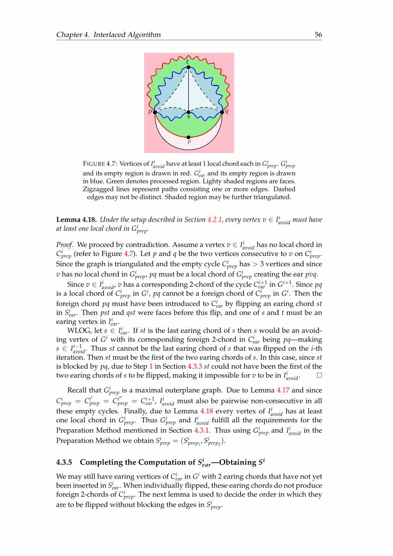
Chapter 4. Interlaced Algorithm 56
FIGURE 4.7: Vertices of Iiavoid have at least 1 local chord each in Gi
prep. Giprep
and its empty region is drawn in red. Giear and its empty region is drawn
in blue. Green denotes processed region. Lighty shaded regions are faces.Zigzagged lines represent paths consisting one or more edges. Dashed
edges may not be distinct. Shaded region may be further triangulated.
Lemma 4.18. Under the setup described in Section 4.2.1, every vertex v ∈ Iiavoid must have
at least one local chord in Giprep.
Proof. We proceed by contradiction. Assume a vertex v ∈ Iiavoid has no local chord in
Ciprep (refer to Figure 4.7). Let p and q be the two vertices consecutive to v on Ci
prep.Since the graph is triangulated and the empty cycle Ci
prep has > 3 vertices and sincev has no local chord in Gi
prep, pq must be a local chord of Giprep creating the ear pvq.
Since v ∈ Iiavoid, v has a corresponding 2-chord of the cycle Ci+1
ear in Gi+1. Since pqis a local chord of Ci
prep in Gi, pq cannot be a foreign chord of Ciprep in Gi. Then the
foreign chord pq must have been introduced to Ciear by flipping an earing chord st
in Siear. Then pst and qst were faces before this flip, and one of s and t must be an
earing vertex in Iiear.
WLOG, let s ∈ Iiear. If st is the last earing chord of s then s would be an avoid-
ing vertex of Gi with its corresponding foreign 2-chord in Ciear being pq—making
s ∈ Ii−1avoid. Thus st cannot be the last earing chord of s that was flipped on the i-th
iteration. Then st must be the first of the two earing chords of s. In this case, since stis blocked by pq, due to Step 1 in Section 4.3.3 st could not have been the first of thetwo earing chords of s to be flipped, making it impossible for v to be in Ii
avoid.
Recall that Giprep is a maximal outerplane graph. Due to Lemma 4.17 and since
Ciprep = Ci′
prep = Ci′′prep = Ci+1
ear , Iiavoid must also be pairwise non-consecutive in all
these empty cycles. Finally, due to Lemma 4.18 every vertex of Iiavoid has at least
one local chord in Giprep. Thus Gi
prep and Iiavoid fulfill all the requirements for the
Preparation Method mentioned in Section 4.3.1. Thus using Giprep and Ii
avoid in thePreparation Method we obtain Si
prep = (Siprep1
, Siprep2
).
4.3.5 Completing the Computation of Siear—Obtaining Si
We may still have earing vertices of Ciear in Gi with 2 earing chords that have not yet
been inserted in Siear. When individually flipped, these earing chords do not produce
foreign 2-chords of Ciprep. The next lemma is used to decide the order in which they
are to be flipped without blocking the edges in Siprep.

Chapter 4. Interlaced Algorithm 57
(a) Initial Configuration (b) Final Configuration
FIGURE 4.8: Cear is drawn in blue, Cprep drawn in red, zigzagged arcsare paths and may overlap, shaded region may be further triangu-lated. Dashed chords of Cprep may be edges of the cycle Cprep. Blue,red and green shades are parts of Gear, Gprep and the processed regionin between respectively. l and m and o are vertices on Cprep such that
lm is a provisioning chord of v
Lemma 4.19. Under the setup described in Section 4.2.1, let u be an earing vertex of Giear
with two earing chords e1 and e2. Furthermore, flipping e1 and e2 individually in Giear
produces e′1 and e′2 respectively—neither of which is a foreign 2-chords of Ciprep. Then if either
of e1 and e2 blocks a provisioning chord lm of Ciprep, then lm must be a singly provisioning
chord of the avoiding vertex u of Ciprep.
Proof. As illustrated in Figure 4.8a, u (earing vertex) is in Iiear with two local chords
e1 = uv and e2 = uw of Ciear (drawn in blue) where neither of their correspond-
ing flipped chord e′1 = pw e′2 = qv are foreign 2-chords of Ci′′prep (drawn in red).
Since degGiear(u) = 4, up and uq must be edges of Ci
ear. Because u is a vertex ofthe independent set Ii
ear in Giear and since uv, up, uq and uw are also edges of Gi
ear,v, p, q, w /∈ Ii
ear. Since we only flip chords incident to earing vertices, none of theedges in vp, pu, qu, qw, vw can be in Si
ear. As a result these 5 edges of Giear is also
present in Gi′′ear.
We are ready to prove the lemma by contradiction. WLOG, assume e1 = uvblocks a doubly provisioning chord lm of Ci
prep. Then both u and v are avoidingvertices of Ci
prep = Ci+1ear in Gi+1. Let x and y be the consecutive vertices of u on Ci
ear
such that x ∈ (yuv) and y ∈ (
yvu) of Ci
ear. Then xy must be a foreign 2-chord of Ci′′prep.
Notice that u and v cannot be consecutive on the cycle Ci′′prep.
We need the following two properties:
1. Property 1 (y and w must be the same vertex): Notice that if w is not a vertexon Ci′′
prep, then (vw, wq, qu) forms a chord-path separating the vertices in (yuv)
from the vertices in (yvu) of the cycle Ci′′
prep in its foreign region. If w is a vertex
on Ci′′prep, and vw is a chord of Ci′′
prep, then vw separates the vertices in (ywv) from
the vertices in (yvw). But then due to Lemma 3.2 xy cannot be a foreign 2-chord
of v since x ∈ (ywv) and y ∈ (
yvw). Thus for xy to be a foreign chord of Ci′′
prep, yand w must be the same vertex.
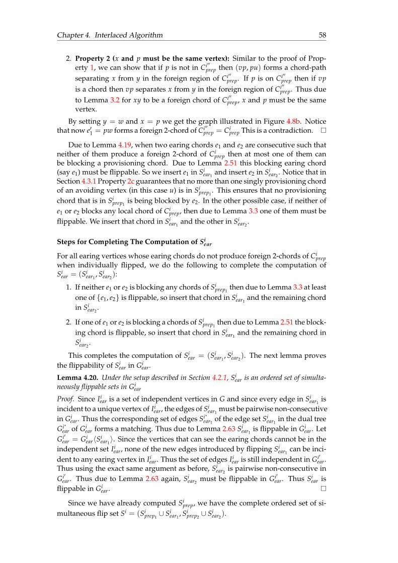
Chapter 4. Interlaced Algorithm 58
2. Property 2 (x and p must be the same vertex): Similar to the proof of Prop-erty 1, we can show that if p is not in Ci′′
prep then (vp, pu) forms a chord-pathseparating x from y in the foreign region of Ci′′
prep. If p is on Ci′′prep then if vp
is a chord then vp separates x from y in the foreign region of Ci′′prep. Thus due
to Lemma 3.2 for xy to be a foreign chord of Ci′′prep, x and p must be the same
vertex.
By setting y = w and x = p we get the graph illustrated in Figure 4.8b. Noticethat now e′1 = pw forms a foreign 2-chord of Ci′′
prep = Ciprep This is a contradiction.
Due to Lemma 4.19, when two earing chords e1 and e2 are consecutive such thatneither of them produce a foreign 2-chord of Ci
prep then at most one of them canbe blocking a provisioning chord. Due to Lemma 2.51 this blocking earing chord(say e1) must be flippable. So we insert e1 in Si
ear1and insert e2 in Si
ear2. Notice that in
Section 4.3.1 Property 2c guarantees that no more than one singly provisioning chordof an avoiding vertex (in this case u) is in Si
prep1. This ensures that no provisioning
chord that is in Siprep1
is being blocked by e2. In the other possible case, if neither ofe1 or e2 blocks any local chord of Ci
prep, then due to Lemma 3.3 one of them must beflippable. We insert that chord in Si
ear1and the other in Si
ear2.
Steps for Completing The Computation of Siear
For all earing vertices whose earing chords do not produce foreign 2-chords of Ciprep
when individually flipped, we do the following to complete the computation ofSi
ear = (Siear1
, Siear2
):
1. If neither e1 or e2 is blocking any chords of Siprep1
then due to Lemma 3.3 at leastone of e1, e2 is flippable, so insert that chord in Si
ear1and the remaining chord
in Siear2
.
2. If one of e1 or e2 is blocking a chords of Siprep1
then due to Lemma 2.51 the block-ing chord is flippable, so insert that chord in Si
ear1and the remaining chord in
Siear2
.
This completes the computation of Siear = (Si
ear1, Si
ear2). The next lemma proves
the flippability of Siear in Gi
ear.
Lemma 4.20. Under the setup described in Section 4.2.1, Siear is an ordered set of simulta-
neously flippable sets in Giear
Proof. Since Iiear is a set of independent vertices in G and since every edge in Si
ear1is
incident to a unique vertex of Iiear, the edges of Si
ear1must be pairwise non-consecutive
in Giear. Thus the corresponding set of edges Si∗
ear1of the edge set Si
ear1in the dual tree
Gi∗ear of Gi
ear forms a matching. Thus due to Lemma 2.63 Siear1
is flippable in Giear. Let
Gi′ear = Gi
ear〈Siear1〉. Since the vertices that can see the earing chords cannot be in the
independent set Iiear, none of the new edges introduced by flipping Si
ear1can be inci-
dent to any earing vertex in Iiear. Thus the set of edges Ii
ear is still independent in Gi′ear.
Thus using the exact same argument as before, Siear2
is pairwise non-consecutive inGi′
ear. Thus due to Lemma 2.63 again, Siear2
must be flippable in Gi′ear. Thus Si
ear isflippable in Gi
ear.
Since we have already computed Siprep, we have the complete ordered set of si-
multaneous flip set Si = (Siprep1∪ Si
ear1, Si
prep2∪ Si
ear2).
Chapter 4. Interlaced Algorithm 59
FIGURE 4.9: If a blocked earing chord produces foreign 2-chord of Ciprep,
its consecutive earing chord is flippable. Giprep and its empty region is
drawn in red. Giear and its empty region is drawn in blue. Green de-
notes processed region. Lighty shaded regions are faces. Zigzagged linesrepresent paths consisting one or more edges. Dashed edges may not be
distinct. Shaded region may be further triangulated.
4.3.6 Flippability of Si
Due to Property 2a of the Preparation Method in Section 4.3.1, Siprep is flippable in
Giprep. Due to Lemma 4.20, Si
ear is flippable in Giear. Since Ci
ear and Ciprep are non-
overlapping empty cycles, none of the chords of Ciear can be consecutive to any
chords in Ciprep—ensuring non-consecutivity among the edges of Si. Thus to show
that Si is an ordered set of flippable sets in Gi, due to Lemma 2.50 we only have toprove that the following two requirements are met.
1. Any edge in the sets of Si that is blocked, its blocking edge is also in the re-spective set.
2. For each of these sets, none of the edges form bad pairs.
The next Lemma provides a proof that in Step 1 of Section 4.3.3 the earing chordthat is flipped in the Si
ear2cannot be blocking any provisioning chord.
Lemma 4.21. Under the setup described in Section 4.2.1, assume we execute Step 1 ofSection 4.3.3, where i > 1. Hence, let e1 and e2 be the two local chords of an earing vertexsuch that e2 is blocked in Gi and flipping e2 individually results in a foreign 2-chord of Ci
prep.Then e2 cannot block any provisioning chord in Si
prep.
Proof. As illustrated in Figure 4.9, let e2 = st be seen by the edges p and q. Since flip-ping e2 individually introduces a foreign 2-chord pq of Ci
prep, there must be exactlyone vertex v between p and q on an arc of Ci
prep. To prove by contradiction, assumee2 is blocked by a provisioning chord of Gi
prep. Then pq is a local 2-chord of Giprep
introducing the ear pqv in Giprep.
Since i > 1, we removed all the ears of G(i−1)′′ear to get Gi
prep, so pvq cannot be an
ear of G(i−1)′′ear . Then pq cannot be a local 2-chord of C(i−1)′′
ear and therefore there mustbe other vertices on the arc
yqp of the cycle C(i−1)′′
ear , which was removed from C(i−1)′′ear
while removing all the ears of G(i−1)′′ear . WLOG let vuq be such an ear making vq a
local chord of C(i−1)′′ear . Then uv and uq edges must be present in the foreign region of
Chapter 4. Interlaced Algorithm 60
Ciprep in Gi. Since vq is a chord of G(i−1)′′
ear , and because no chord in G(i−1)′′ear can be an
edge in G(i−1)′′prep , vq cannot be an edge of G(i−1)′′
prep = Giear. Since sq must be an edge in
Giear, s 6= v. Then s must be in the foreign region of Ci
prep and hence no local chord ofCi
prep when flipped can be incident to s. Thus e2 = st cannot block any provisioningchords in Si
prep.
The next two lemmas prove that if an edge in Si is a blocked chord, then the edgeblocking it is also in the corresponding edge set in Si.
Lemma 4.22. Under the setup described in Section 4.2.1, if any provisioning chord in Si isblocked, then its corresponding blocking edge must also be present in the respective edge setof Si.
Proof. Let pq be the provisioning chord of the vertex v ∈ Iiavoid that is blocked by uv.
We prove this lemma in two steps. In Case 4.3.6 we prove that if pq ∈ Siprep1
thenuv ∈ Si
ear1. In Case 4.3.6 we prove that if pq ∈ Si
prep2then uv ∈ Si
ear2.
Case 1 (pq ∈ Siear1
=⇒ uv ∈ Siprep1
): Due to Property 2c of the Preparation Methodin Section 4.3.1, no two earing chords of the same earing vertex can both be blockingprovisioning chords in Si
prep1. Due to Lemma 4.21, in Step 1 of Section 4.3.3, the ear-
ing chord inserted in Siear1
cannot block any provisioning chords in Siprep1
. Observethat in every other step listed in Section 4.3.3 and Section 4.3.5, when selecting theorder in which the earing chords of an earing vertex are flipped, we have explicitlyensured that any earing chord of the earing vertex that is blocking a provisioningchord in Si
prep1is always inserted in Si
ear1. Thus if pq ∈ Si
prep1, uv must be in Si
ear1.
Case 2 (pq ∈ Siprep2
=⇒ uv ∈ Siear2
): Since v must have a corresponding foreign2-chord in Ci+1
ear = Ciprep in Gi+1, v is separated from u in the foreign region of Ci+1
ear .Thus uv cannot be an edge in Gi+1. Therefore uv must have been flipped in Gi′ whichmeans uv ∈ Si
ear2
Since Si := (Siear1 ∪ Si
prep1, Si
ear2 ∪ Si
prep2), the proof of the lemma is com-
plete by the above two cases.
Lemma 4.23. Under the setup described in Section 4.2.1, if any earing chord in Si is blocked,then its corresponding blocking edge must also be present in the respective edge set of Si.
Proof. As listed in Section 4.3.3 and Section 4.3.5, there are four cases in which anearing chord is inserted in Si. These cases are:
1. Case 1 (Section 4.3.3 Step 1): Assume, we have an earing vertex v with twoearing chords e1 and e2 where e2 is blocked. Moreover, individually flipping e2in Gi produces parallel edges with a foreign 2-chord of Ci′
prep. In this case e1 isinserted in Si
ear1. Due to Lemma 2.51, e1 is flippable in Gi. The proof that e2 is
also flippable is coverted in Case 4.
2. Case 2 (Section 4.3.3 Step 2, Section 4.3.5 Step 1): Assume, an earing chord eblocks a provisioning chord in Si
prep1, where e is not consecutive to any other
earing chords. In this case the earing chord is inserted in Siear1
. Due to Lemma2.51, e is flippable in Gi.
3. Case 3 (Section 4.3.3 Step 3, Section 4.3.5 Step 1): Assume we have an earingvertex u having two earing chords e1 and e2, neither of which are blockingprovisioning chords in Si
ear1. In this case, due to Lemma 3.3, we can assume
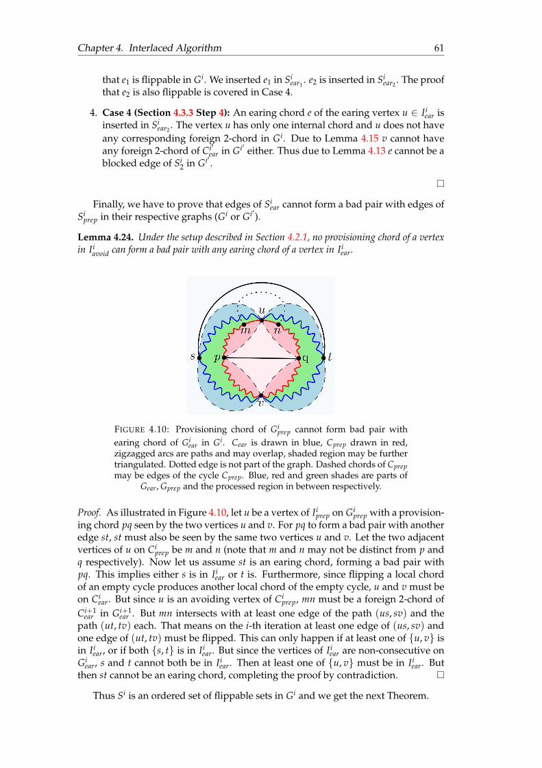
Chapter 4. Interlaced Algorithm 61
that e1 is flippable in Gi. We inserted e1 in Siear1
. e2 is inserted in Siear2
. The proofthat e2 is also flippable is covered in Case 4.
4. Case 4 (Section 4.3.3 Step 4): An earing chord e of the earing vertex u ∈ Iiear is
inserted in Siear2
. The vertex u has only one internal chord and u does not haveany corresponding foreign 2-chord in Gi. Due to Lemma 4.15 v cannot haveany foreign 2-chord of Ci′
ear in Gi′ either. Thus due to Lemma 4.13 e cannot be ablocked edge of Si
2 in Gi′ .
Finally, we have to prove that edges of Siear cannot form a bad pair with edges of
Siprep in their respective graphs (Gi or Gi′).
Lemma 4.24. Under the setup described in Section 4.2.1, no provisioning chord of a vertexin Ii
avoid can form a bad pair with any earing chord of a vertex in Iiear.
FIGURE 4.10: Provisioning chord of Giprep cannot form bad pair with
earing chord of Giear in Gi. Cear is drawn in blue, Cprep drawn in red,
zigzagged arcs are paths and may overlap, shaded region may be furthertriangulated. Dotted edge is not part of the graph. Dashed chords of Cprepmay be edges of the cycle Cprep. Blue, red and green shades are parts of
Gear, Gprep and the processed region in between respectively.
Proof. As illustrated in Figure 4.10, let u be a vertex of Iiprep on Gi
prep with a provision-ing chord pq seen by the two vertices u and v. For pq to form a bad pair with anotheredge st, st must also be seen by the same two vertices u and v. Let the two adjacentvertices of u on Ci
prep be m and n (note that m and n may not be distinct from p andq respectively). Now let us assume st is an earing chord, forming a bad pair withpq. This implies either s is in Ii
ear or t is. Furthermore, since flipping a local chordof an empty cycle produces another local chord of the empty cycle, u and v must beon Ci
ear. But since u is an avoiding vertex of Ciprep, mn must be a foreign 2-chord of
Ci+1ear in Gi+1
ear . But mn intersects with at least one edge of the path (us, sv) and thepath (ut, tv) each. That means on the i-th iteration at least one edge of (us, sv) andone edge of (ut, tv) must be flipped. This can only happen if at least one of u, v isin Ii
ear, or if both s, t is in Iiear. But since the vertices of Ii
ear are non-consecutive onGi
ear, s and t cannot both be in Iiear. Then at least one of u, v must be in Ii
ear. Butthen st cannot be an earing chord, completing the proof by contradiction.
Thus Si is an ordered set of flippable sets in Gi and we get the next Theorem.
Chapter 4. Interlaced Algorithm 62
Theorem 4.25. Under the setup described in Section 4.2.1, Si is an ordered set of flippablesets on Gi.
4.3.7 Initiating the 1st Iteration
A Hamiltonian cycle in a plane graph has two empty regions, one on each side.Thus it defines two distinct empty cycles- each having the same Hamiltonian cycle,but with a distinct empty region of the cycle. Once we have obtained a triangulationG1 with a Hamiltonian cycle H, we name these two empty cycles C1
ear and C1prep. In
the interlaced algorithm, for the i-th iteration, we need Ii−1avoid to compute Ii
ear. Butfor the first iteration, we do not have I0
avoid. The next lemma shows how to computeI1ear such that none of the vertices in I1
ear has a corresponding 2-chord of C1ear in G1.
However, we can only guarantee that |I1ear| ≥ n/12 (instead of n/6).
Lemma 4.26. On the first iteration, we can find a set of independent vertices I1ear of degree
at most 4 in G1ear such that |I1
ear| ≥ n/12. Furthermore, none of the vertices in I1ear is an
avoiding vertex in G1.
Proof. In our 1st iteration, we shall create ears in G1ear and we shall prepare G1
prepfor the next iteration. Due to Theorem 2.66 we can compute an independent set ofvertices I of size n/6 in G1
ear such that every vertex has at most degree 4 in G1ear.
If at least half of these vertices are non-avoiding vertices in Ciear, then the proof is
complete. But if more than half of these vertices are avoiding vertices, each of themhas a corresponding foreign 2-chord on C1
ear. Since the two empty cycles are the samecycles but with different empty regions, this means G1
prep currently has at least n/12ears. Since the graph by Definition 2.1 is simple, none of these vertices can have aforeign 2-chord in G1
prep. Thus none of these vertices have a foreign 2-chord in G1prep.
So we relabel G1prep as G1
ear and G1ear as G1
prep, and use these vertices as the set of I1ear
for our first iteration.
Once we have obtained I1ear we can continue the 1st iteration as explained for the
i-th iteration.
Chapter 4. Interlaced Algorithm 63
4.4 The Preparation Method
The Preparation Method takes a maximal outerplane graph G = (V, E) with itsmaximal cycle C and a set of pairwise non-consecutive vertices Iavoid on C, whereeach vertex in Iavoid has at least one chord in G. Vertices of Iavoid are called avoidingvertices as these are the vertices that we would like to avoid from creating ears withfor the next iteration. Vertices in V that are not in Iavoid are called safe vertices. ThePreparation Method returns an ordered set of flippable sets Sprep = (Sprep1 , Sprep2) onG. Let G′′ = G〈Sprep〉. In G′′, for all vertices v ∈ Iavoid, either v has at least 3 internalchords, or v dominates another vertex u where u 6∈ Iavoid.
4.4.1 Properties of Preparation Method
1. Input parameters of Preparation Method:
(a) A maximal outerplane graph G = (V, E) with the maximal empty cycledenoted by C.
(b) A set of pairwise non-consecutive vertices Iavoid on C.
(c) Each vertex of Iavoid has at least one chord in G.
2. Output parameters of Preparation Method:
(a) Returns an ordered set of two simultaneous flip sets Sprep := (Sprep1 , Sprep2)on G consisting of only provisioning chords. (See Lemma 4.45 Property 1)
(b) In G′′prep := Gprep〈Sprep〉, for every vertex v ∈ Iavoid at least one of the
following is true (See Lemma 4.45 Property 2):
i. v has at least 3 local chords in Gi′′ear.
ii. v dominates a vertex u where u 6∈ Iavoid.
(c) No more than one singly provisioning chord of any vertex v ∈ Iavoid is inSprep1 . (See Lemma 4.45 Property 3)
The Preparation Method achieves this in two steps:
1. Divide G into a set of smaller subgraphs and assign each of the vertex in Iavoidto one partitioned subgraph.
2. Insert provisioning chords in each partitioned subgraph to Sprep so that theassigned vertices of each subgraph either dominate a vertex not in Iavoid, orthey have at least 3 internal chords in G′′.
4.4.2 Preliminaries
We start with some definitions that are used in this section.
Definition 4.27 (Partitioned Subgraph). Given a maximal outerplane graph G = (V, E),its maximal cycle C and a set of pairwise non-consecutive vertices Iavoid on C, where eachof the vertices in Iavoid has at least 1 local chord in G. The graph G is split into a set of ksubgraphs Gp := g1, g2, · · · , gk where for all 1 ≤ i ≤ k, gi = (Vi, Ei) and each subgraphgi is called a partitioned subgraph having the following properties:
1. The partitioned subgraphs in Gp are pairwise non-overlapping maximal outerplanesubgraphs of G.
Chapter 4. Interlaced Algorithm 64
2. Every vertex and edge of G is present in at least one partitioned subgraph.
3. Every vertex v ∈ Iavoid, is colored red in exactly one partitioned subgraph in Gp. Inall the other partitioned subgraphs where v is present, v is colored black. Vertices thatare not in Iavoid are coloured green.
4. No two red vertices are neighbours in a partitioned subgraph.
5. No green vertex appears in more than one partitioned subgraph of Gp.
6. Every partitioned subgraph contains at least one green vertex.
7. No black vertex is consecutive to two red vertices on the maximal empty cycle of anypartitioned subgraph.
We now extend the definition of provisioning chord to the context of partitionedsubgraphs.
Definition 4.28 (Provisioning chord). Let G = (V, E) be a maximal outerplane graphwith the maximal cycle C, and a set of pairwise non-consecutive vertices Iavoid ⊆ V onC. Let Gp be the set of partitioned subgraphs of G. Then for a partitioned subgraph gi =(Vi, Ei) ∈ Gp, let pq be a local chord of gi and u be a red vertex in gi such that pq is seen byu in the local region of gi. Then pq is a provisioning chord of u. Furthermore u is calledthe corresponding avoiding vertex of the provisioning chord pq. If a provisioning chordis seen by two distinct red vertices in its respective partitioned subgraph, then it is called adoubly provisioning chord. Otherwise it is called a singly provisioning chord.
4.4.3 Requiring Avoiding Vertices to Have at Least One Internal Chord
One may ask why the Preparation Method Property 1c in Section 4.4.1 is necessary.Unless every vertex in Iavoid has at least 1 internal chord in G, there may be somevertices whose degree must be increased by 3 in the Preparation Method. At firstglance, it may seem possible by increasing the degree by 1 in the first simultaneousflip and then adding another 2 to the degree in the second simultaneous flip. InFigure 4.11(a) G has 3 avoiding vertices u, v and w, and 3 provisioning chords am, f gand gh. On the first simultaneous flip by flipping all 3 of the provisioning chords, weget G′ illustrated in Figure 4.11(b). Notice that in G′ each of the vertices u, v and wrequire 2 more chords to meet their requirement of having at least 3 internal chords.The provisioning chords in G′ are c f , cg, ag, gm, gk, hk. However, since cg and agare consecutive, and gk and gm are consecutive, due to Lemma 2.50 Condition 1 theycannot be flipped together in the second simultaneous flips. This makes it impossibleto ensure that u, v and w each would have at least 3 internal chords by only flippingprovisioning chords using 2 simultaneous flips.
Furthermore, regardless of which of the provisioning chords c f , cg, ag, gm, gk, hkare flipped in G′ on the second simultaneous flip, neither of u, v or w dominates anyof the green vertices in the resulting graph. Thus Preparation Method Property 1c inSection 4.4.1 is necessary.
4.4.4 Maximal Outerplane Graph Partitioning Algorithm
The Algorithm GENERATESUBGRAPHS(G, Iavoid) takes a maximal outerplane graphG and a set of non-consecutive vertices Iavoid on its maximal cycle. Then every vertexof Iavoid is coloured red and the remaining vertices are coloured green in G. Next, Gis inserted into the stack of unprocessed graphs S.
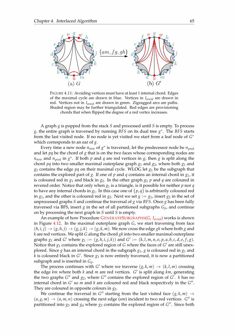
Chapter 4. Interlaced Algorithm 65
FIGURE 4.11: Avoiding vertices must have at least 1 internal chord. Edgesof the maximal cycle are drawn in blue. Vertices in Iavoid are drawn inred. Vertices not in Iavoid are drawn in green. Zigzagged arcs are paths.Shaded region may be further triangulated. Red edges are provisioning
chords that when flipped the degree of a red vertex increases.
A graph g is popped from the stack S and processed until S is empty. To processg, the entire graph is traversed by running BFS on its dual tree g∗. The BFS startsfrom the last visited node. If no node is yet visited we start from a leaf node of G∗
which corresponds to an ear of g.Every time a new node nnew of g∗ is traversed, let the predecessor node be npred
and let pq be the chord of g that is on the two faces whose corresponding nodes arennew and npred in g∗. If both p and q are red vertices in g, then g is split along thechord pq into two smaller maximal outerplane graph g1 and g2, where both g1 andg2 contains the edge pq on their maximal cycle. WLOG let g1 be the subgraph thatcontains the explored part of g. If one of p and q contains an internal chord in g1, itis coloured red in g1 and black in g2. In the other graph g2 p and q are coloured inrevered order. Notice that only when g1 is a triangle, is it possible for neither p nor qto have any internal chords in g1. In this case one of p, q is arbitrarily coloured redin g1, and the other is coloured red in g2. Next we set g := g1, insert g2 in the set ofunprocessed graphs S and continue the traversal of g via BFS. Once g has been fullytraversed via BFS, insert g in the set of all partitioned subgraphs Gp, and continueon by processing the next graph in S until S is empty.
An example of how Procedure GENERATESUBGRAPHS(G, Iavoid) works is shownin Figure 4.12. In the maximal outerplane graph G, we start traversing from face(h, i, j)→ (g, h, j)→ (g, j, k)→ (g, k, m). We now cross the edge gk where both g andk are red vertices. We split G along the chord gk into two smaller maximal outerplanegraphs g1 and G′ where g1 := (g, h, i, j, k)) and G′ := (k, l, m, n, o, p, a, b, c, d, e, f , g).Notice that g1 contains the explored region of G where the faces of G′ are still unex-plored. Since g has an internal chord in the subgraph g1, g is coloured red in g1 andk is coloured black in G′. Since g1 is now entirely traversed, it is now a partitionedsubgraph and is inserted in Gp.
The process continues with G′ where we traverse (g, k, m) → (k, l, m) crossingthe edge km where both k and m are red vertices. G′ is split along km, generatingthe two graphs G′′ and g2, where G′′ contains the explored region of G′. k has nointernal chord in G′ so m and k are coloured red and black respectively in the G′′.They are coloured in opposite colours in g2.
We continue the traversal in G′′ starting from the last visited face (g, k, m) →(a, g, m) → (a, m, n) crossing the next edge (am) incident to two red vertices. G′′ ispartitioned into g3 and g4 where g3 contains the explored region of G′′. Since both

Chapter 4. Interlaced Algorithm 66
a and m has internal chords in G′′, since both a and m has an internal chord in g3,a is arbitrarily coloured red in g3 and m is coloured black. The vertices a and mare coloured in opposite colours in g4. BFS continues in g3 traversing (a, g, m) →(a, f , g) → (a, b, f ) → (b, c, f ) → (c, d, e) without crossing any edge connectingtwo red vertices. Since g3 is fully explored, it is now a partitioned subgraph andis inserted in Gp. Similarly using BFS g2 and g4 are also traversed but since thesegraphs do not contain any chord incident to two red vertices, these graphs are notsplit any further. g2 and g4 also get inserted to Gp. At the end of the algorithm thecomputed set of all partitioned subgraphs Gp = g1, g2, g3, g4.
4.4.5 Colouring of the Vertices and the Overall Goal
In each of the partitioned subgraph gi ∈ Gp, the vertices are divided into threecolours—green, red and black. All vertices that are not in Iavoid are coloured green.Each vertex v ∈ Iavoid is coloured red in exactly one partitioned subgraph in Gp. In allother partitioned subgraphs that contain v, v is coloured black. In each partitionedsubgraph gi we compute an ordered set of two simultaneous flip sets si := (si1 , si2)consisting of only provisioning chords of the red vertices in gi. Once we have com-puted si for all partitioned subgraphs gi where 1 ≤ i ≤ k, we compute Sprep :=⋃k
i=1 si.The goal of these two simultaneous flips is to obtain G′′ := G〈Sprep〉where every
red vertex of gi meets Property 2b in Section 4.4.1 in G′′. This is done by ensuringthat for any red vertex in gi, it either dominates a green vertex in G′′, or it has at least3 chords in G′′.
One may ask why we split the graph into a set of partitioned subgraphs and as-sign a subset of vertices of Iavoid as red vertices to each partitioned subgraph. This isbecause as a result of no two red vertices being adjacent in a partitioned subgraph,flipping a provisioning chord of a red vertex does not reduce the degree of any otherred vertex in the partitioned subgraph. Thus by this method of only flipping provi-sioning chords, while meeting the degree requirement of one red vertex, we do notrisk reducing the degree of some other red vertex in the graph.
4.4.6 Procedure GENERATESUBGRAPHS(G, Iavoid) Generates PartitionedSubgraphs
The next few Lemmas are used to prove that the partitioned subgraphs in Gp gen-erated by the Procedure GENERATESUBGRAPHS(G, Iavoid) indeed have all the prop-erties of Partitioned Subgraphs. Using these lemmas Theorem 4.35 proves that Gpconsists of partitioned subgraphs of G.
Lemma 4.29. The partitioned subgraphs in Gp generated by the ProcedureGENERATESUBGRAPHS(G, Iavoid) meet the following properties:
1. The partitioned subgraphs in Gp are pairwise non-overlapping maximal outerplanesubgraphs of G.
2. Every vertex and edge of G is in at least one partitioned subgraph in Gp.
Proof. The original graph G is a maximal outerplane graph. We run BFS on the dualtree G∗ of G, and every time we cross an edge whose corresponding edge in theprimal graph connects two red vertices, we split the tree into two smaller subtreesby removing that edge. Thus, each of our resulting partitioned subgraphs is a primalmaximal outerplane graph to some dual tree that is a subtree of G∗. Furthermore,
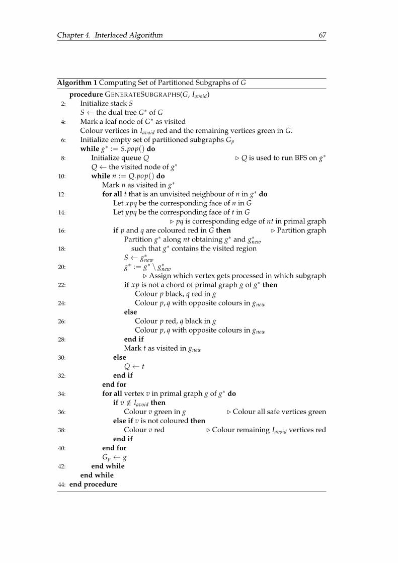
Chapter 4. Interlaced Algorithm 67
Algorithm 1 Computing Set of Partitioned Subgraphs of G
procedure GENERATESUBGRAPHS(G, Iavoid)2: Initialize stack S
S← the dual tree G∗ of G4: Mark a leaf node of G∗ as visited
Colour vertices in Iavoid red and the remaining vertices green in G.6: Initialize empty set of partitioned subgraphs Gp
while g∗ := S.pop() do8: Initialize queue Q . Q is used to run BFS on g∗
Q← the visited node of g∗
10: while n := Q.pop() doMark n as visited in g∗
12: for all t that is an unvisited neighbour of n in g∗ doLet xpq be the corresponding face of n in G
14: Let ypq be the corresponding face of t in G. pq is corresponding edge of nt in primal graph
16: if p and q are coloured red in G then . Partition graphPartition g∗ along nt obtaining g∗ and g∗new
18: such that g∗ contains the visited regionS← g∗new
20: g∗ := g∗ \ g∗new. Assign which vertex gets processed in which subgraph
22: if xp is not a chord of primal graph g of g∗ thenColour p black, q red in g
24: Colour p, q with opposite colours in gnewelse
26: Colour p red, q black in gColour p, q with opposite colours in gnew
28: end ifMark t as visited in gnew
30: elseQ← t
32: end ifend for
34: for all vertex v in primal graph g of g∗ doif v /∈ Iavoid then
36: Colour v green in g . Colour all safe vertices greenelse if v is not coloured then
38: Colour v red . Colour remaining Iavoid vertices redend if
40: end forGp ← g
42: end whileend while
44: end procedure
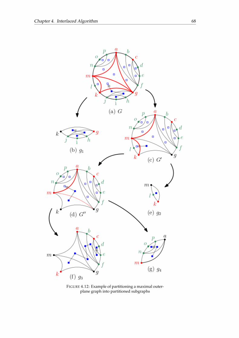
Chapter 4. Interlaced Algorithm 68
FIGURE 4.12: Example of partitioning a maximal outer-plane graph into partitioned subgraphs
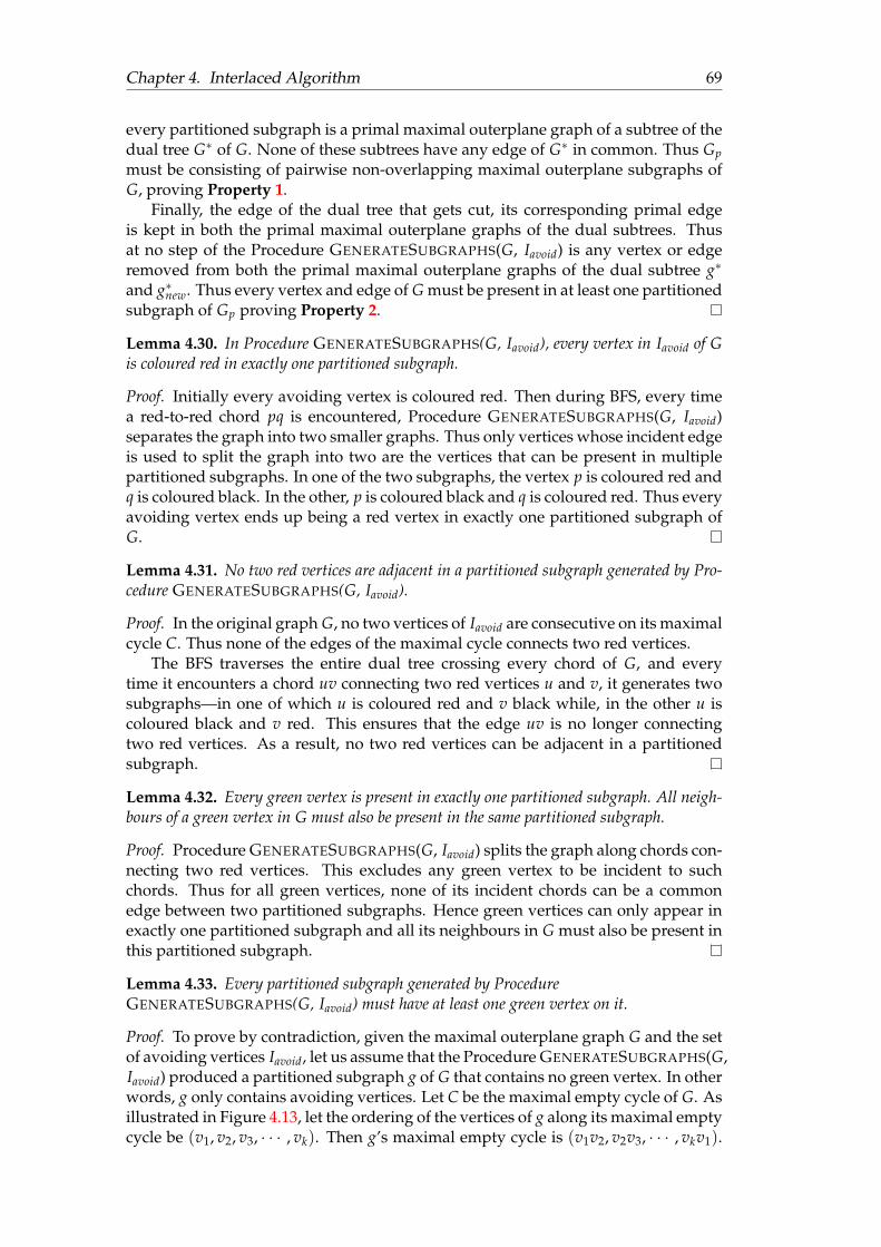
Chapter 4. Interlaced Algorithm 69
every partitioned subgraph is a primal maximal outerplane graph of a subtree of thedual tree G∗ of G. None of these subtrees have any edge of G∗ in common. Thus Gpmust be consisting of pairwise non-overlapping maximal outerplane subgraphs ofG, proving Property 1.
Finally, the edge of the dual tree that gets cut, its corresponding primal edgeis kept in both the primal maximal outerplane graphs of the dual subtrees. Thusat no step of the Procedure GENERATESUBGRAPHS(G, Iavoid) is any vertex or edgeremoved from both the primal maximal outerplane graphs of the dual subtree g∗
and g∗new. Thus every vertex and edge of G must be present in at least one partitionedsubgraph of Gp proving Property 2.
Lemma 4.30. In Procedure GENERATESUBGRAPHS(G, Iavoid), every vertex in Iavoid of Gis coloured red in exactly one partitioned subgraph.
Proof. Initially every avoiding vertex is coloured red. Then during BFS, every timea red-to-red chord pq is encountered, Procedure GENERATESUBGRAPHS(G, Iavoid)separates the graph into two smaller graphs. Thus only vertices whose incident edgeis used to split the graph into two are the vertices that can be present in multiplepartitioned subgraphs. In one of the two subgraphs, the vertex p is coloured red andq is coloured black. In the other, p is coloured black and q is coloured red. Thus everyavoiding vertex ends up being a red vertex in exactly one partitioned subgraph ofG.
Lemma 4.31. No two red vertices are adjacent in a partitioned subgraph generated by Pro-cedure GENERATESUBGRAPHS(G, Iavoid).
Proof. In the original graph G, no two vertices of Iavoid are consecutive on its maximalcycle C. Thus none of the edges of the maximal cycle connects two red vertices.
The BFS traverses the entire dual tree crossing every chord of G, and everytime it encounters a chord uv connecting two red vertices u and v, it generates twosubgraphs—in one of which u is coloured red and v black while, in the other u iscoloured black and v red. This ensures that the edge uv is no longer connectingtwo red vertices. As a result, no two red vertices can be adjacent in a partitionedsubgraph.
Lemma 4.32. Every green vertex is present in exactly one partitioned subgraph. All neigh-bours of a green vertex in G must also be present in the same partitioned subgraph.
Proof. Procedure GENERATESUBGRAPHS(G, Iavoid) splits the graph along chords con-necting two red vertices. This excludes any green vertex to be incident to suchchords. Thus for all green vertices, none of its incident chords can be a commonedge between two partitioned subgraphs. Hence green vertices can only appear inexactly one partitioned subgraph and all its neighbours in G must also be present inthis partitioned subgraph.
Lemma 4.33. Every partitioned subgraph generated by ProcedureGENERATESUBGRAPHS(G, Iavoid) must have at least one green vertex on it.
Proof. To prove by contradiction, given the maximal outerplane graph G and the setof avoiding vertices Iavoid, let us assume that the Procedure GENERATESUBGRAPHS(G,Iavoid) produced a partitioned subgraph g of G that contains no green vertex. In otherwords, g only contains avoiding vertices. Let C be the maximal empty cycle of G. Asillustrated in Figure 4.13, let the ordering of the vertices of g along its maximal emptycycle be (v1, v2, v3, · · · , vk). Then g’s maximal empty cycle is (v1v2, v2v3, · · · , vkv1).
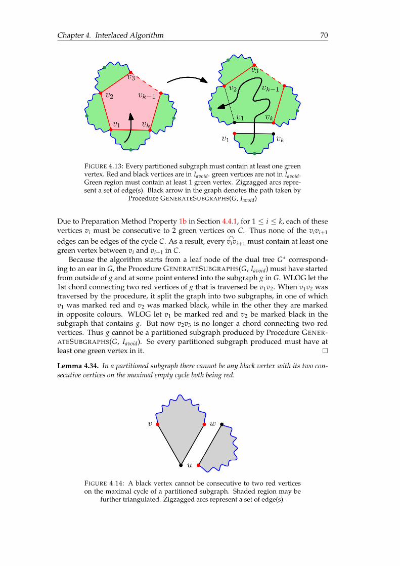
Chapter 4. Interlaced Algorithm 70
FIGURE 4.13: Every partitioned subgraph must contain at least one greenvertex. Red and black vertices are in Iavoid. green vertices are not in Iavoid.Green region must contain at least 1 green vertex. Zigzagged arcs repre-sent a set of edge(s). Black arrow in the graph denotes the path taken by
Procedure GENERATESUBGRAPHS(G, Iavoid)
Due to Preparation Method Property 1b in Section 4.4.1, for 1 ≤ i ≤ k, each of thesevertices vi must be consecutive to 2 green vertices on C. Thus none of the vivi+1
edges can be edges of the cycle C. As a result, everyy
vivi+1 must contain at least onegreen vertex between vi and vi+1 in C.
Because the algorithm starts from a leaf node of the dual tree G∗ correspond-ing to an ear in G, the Procedure GENERATESUBGRAPHS(G, Iavoid) must have startedfrom outside of g and at some point entered into the subgraph g in G. WLOG let the1st chord connecting two red vertices of g that is traversed be v1v2. When v1v2 wastraversed by the procedure, it split the graph into two subgraphs, in one of whichv1 was marked red and v2 was marked black, while in the other they are markedin opposite colours. WLOG let v1 be marked red and v2 be marked black in thesubgraph that contains g. But now v2v3 is no longer a chord connecting two redvertices. Thus g cannot be a partitioned subgraph produced by Procedure GENER-ATESUBGRAPHS(G, Iavoid). So every partitioned subgraph produced must have atleast one green vertex in it.
Lemma 4.34. In a partitioned subgraph there cannot be any black vertex with its two con-secutive vertices on the maximal empty cycle both being red.
FIGURE 4.14: A black vertex cannot be consecutive to two red verticeson the maximal cycle of a partitioned subgraph. Shaded region may be
further triangulated. Zigzagged arcs represent a set of edge(s).
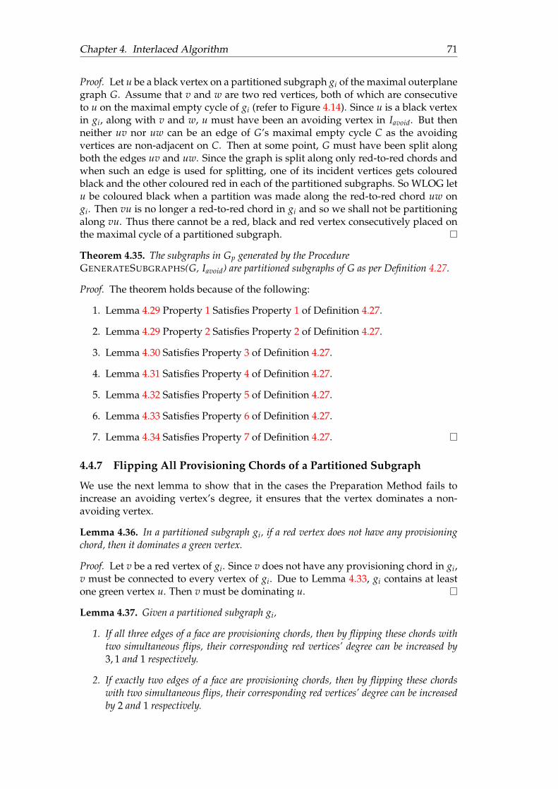
Chapter 4. Interlaced Algorithm 71
Proof. Let u be a black vertex on a partitioned subgraph gi of the maximal outerplanegraph G. Assume that v and w are two red vertices, both of which are consecutiveto u on the maximal empty cycle of gi (refer to Figure 4.14). Since u is a black vertexin gi, along with v and w, u must have been an avoiding vertex in Iavoid. But thenneither uv nor uw can be an edge of G’s maximal empty cycle C as the avoidingvertices are non-adjacent on C. Then at some point, G must have been split alongboth the edges uv and uw. Since the graph is split along only red-to-red chords andwhen such an edge is used for splitting, one of its incident vertices gets colouredblack and the other coloured red in each of the partitioned subgraphs. So WLOG letu be coloured black when a partition was made along the red-to-red chord uw ongi. Then vu is no longer a red-to-red chord in gi and so we shall not be partitioningalong vu. Thus there cannot be a red, black and red vertex consecutively placed onthe maximal cycle of a partitioned subgraph.
Theorem 4.35. The subgraphs in Gp generated by the ProcedureGENERATESUBGRAPHS(G, Iavoid) are partitioned subgraphs of G as per Definition 4.27.
Proof. The theorem holds because of the following:
1. Lemma 4.29 Property 1 Satisfies Property 1 of Definition 4.27.
2. Lemma 4.29 Property 2 Satisfies Property 2 of Definition 4.27.
3. Lemma 4.30 Satisfies Property 3 of Definition 4.27.
4. Lemma 4.31 Satisfies Property 4 of Definition 4.27.
5. Lemma 4.32 Satisfies Property 5 of Definition 4.27.
6. Lemma 4.33 Satisfies Property 6 of Definition 4.27.
7. Lemma 4.34 Satisfies Property 7 of Definition 4.27.
4.4.7 Flipping All Provisioning Chords of a Partitioned Subgraph
We use the next lemma to show that in the cases the Preparation Method fails toincrease an avoiding vertex’s degree, it ensures that the vertex dominates a non-avoiding vertex.
Lemma 4.36. In a partitioned subgraph gi, if a red vertex does not have any provisioningchord, then it dominates a green vertex.
Proof. Let v be a red vertex of gi. Since v does not have any provisioning chord in gi,v must be connected to every vertex of gi. Due to Lemma 4.33, gi contains at leastone green vertex u. Then v must be dominating u.
Lemma 4.37. Given a partitioned subgraph gi,
1. If all three edges of a face are provisioning chords, then by flipping these chords withtwo simultaneous flips, their corresponding red vertices’ degree can be increased by3, 1 and 1 respectively.
2. If exactly two edges of a face are provisioning chords, then by flipping these chordswith two simultaneous flips, their corresponding red vertices’ degree can be increasedby 2 and 1 respectively.
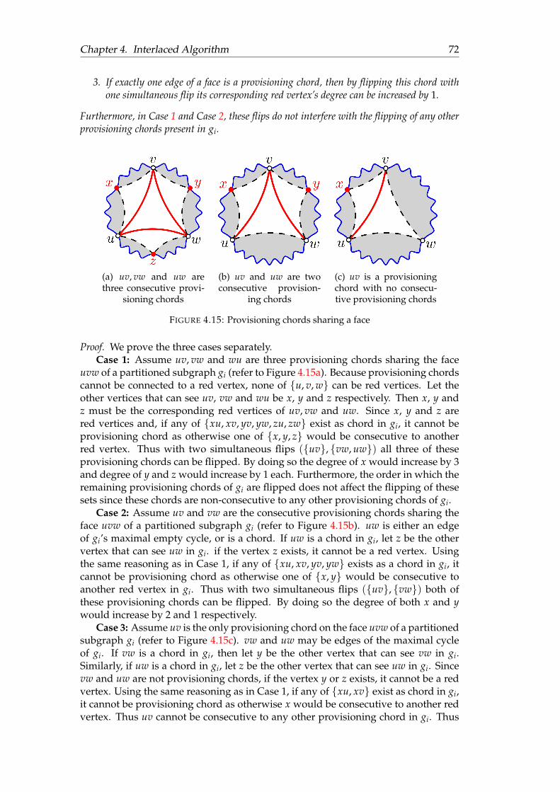
Chapter 4. Interlaced Algorithm 72
3. If exactly one edge of a face is a provisioning chord, then by flipping this chord withone simultaneous flip its corresponding red vertex’s degree can be increased by 1.
Furthermore, in Case 1 and Case 2, these flips do not interfere with the flipping of any otherprovisioning chords present in gi.
(a) uv, vw and uw arethree consecutive provi-
sioning chords
(b) uv and uw are twoconsecutive provision-
ing chords
(c) uv is a provisioningchord with no consecu-tive provisioning chords
FIGURE 4.15: Provisioning chords sharing a face
Proof. We prove the three cases separately.Case 1: Assume uv, vw and wu are three provisioning chords sharing the face
uvw of a partitioned subgraph gi (refer to Figure 4.15a). Because provisioning chordscannot be connected to a red vertex, none of u, v, w can be red vertices. Let theother vertices that can see uv, vw and wu be x, y and z respectively. Then x, y andz must be the corresponding red vertices of uv, vw and uw. Since x, y and z arered vertices and, if any of xu, xv, yv, yw, zu, zw exist as chord in gi, it cannot beprovisioning chord as otherwise one of x, y, z would be consecutive to anotherred vertex. Thus with two simultaneous flips (uv, vw, uw) all three of theseprovisioning chords can be flipped. By doing so the degree of x would increase by 3and degree of y and z would increase by 1 each. Furthermore, the order in which theremaining provisioning chords of gi are flipped does not affect the flipping of thesesets since these chords are non-consecutive to any other provisioning chords of gi.
Case 2: Assume uv and vw are the consecutive provisioning chords sharing theface uvw of a partitioned subgraph gi (refer to Figure 4.15b). uw is either an edgeof gi’s maximal empty cycle, or is a chord. If uw is a chord in gi, let z be the othervertex that can see uw in gi. if the vertex z exists, it cannot be a red vertex. Usingthe same reasoning as in Case 1, if any of xu, xv, yv, yw exists as a chord in gi, itcannot be provisioning chord as otherwise one of x, y would be consecutive toanother red vertex in gi. Thus with two simultaneous flips (uv, vw) both ofthese provisioning chords can be flipped. By doing so the degree of both x and ywould increase by 2 and 1 respectively.
Case 3: Assume uv is the only provisioning chord on the face uvw of a partitionedsubgraph gi (refer to Figure 4.15c). vw and uw may be edges of the maximal cycleof gi. If vw is a chord in gi, then let y be the other vertex that can see vw in gi.Similarly, if uw is a chord in gi, let z be the other vertex that can see uw in gi. Sincevw and uw are not provisioning chords, if the vertex y or z exists, it cannot be a redvertex. Using the same reasoning as in Case 1, if any of xu, xv exist as chord in gi,it cannot be provisioning chord as otherwise x would be consecutive to another redvertex. Thus uv cannot be consecutive to any other provisioning chord in gi. Thus

Chapter 4. Interlaced Algorithm 73
uv can be flipped in either the first simultaneous flip si1 or the second simultaneousflip si2 . By doing so the degree of x would increase by 1.
The notion of branches come useful in the next Lemma.
Definition 4.38 (Branch). Given a tree T with a node u, a branch of u is a maximal subtreein T containing u as a leaf node.
Given a partitioned subgraph gi, the next lemma provides us a way to buildsi := (si1 , si2) ensuring that every red vertex’s degree increases by the number ofprovisioning chords it has in its respective partitioned subgraph.
Lemma 4.39. Let gi be a partitioned subgraph, with a provisioning chord pq being prese-lected to be in one of the flip sets in si := (si1 , si2), then:
1. All the remaining provisioning chords in gi can be inserted in one of si1 and si2 .
2. si is an ordered set of flippable sets on gi.
3. The degree of each red vertex in g′′i := gi〈si〉 increases at least by the number ofprovisioning chords it has in si.
Proof. To complete this proof, first we see how given a face of gi with at most onepreselected provisioning chord inserted in si, we can insert the remaining chords insi while keeping si flippable. We divide the problem into the following 4 cases.
Let e be an edge of a face f of gi that has already been inserted to si1 or si2 :Case 1: Assume f has 3 provisioning chords.
1. If e ∈ si1 , then the other two chords on f are inserted in si2 .
2. If e ∈ si2 , then insert one of the remaining two provisioning chords on fin si1 and the other in si2 .
Due to Lemma 4.37 none of these chords can be consecutive to any other provision-ing chords. As a result, they are flippable in this order regardless in the order otherprovisioning chords are inserted in si.
Case 2: Assume f has 2 provisioning chords.
1. If e ∈ si1 , then the other provisioning chord on f is inserted in si2 .
2. If e ∈ si2 , then the other provisioning chord on f is inserted in si1 .
Due to Lemma 4.37 none of these chords can be consecutive to any other provision-ing chords. As a result, they are flippable in this order regardless in the order otherprovisioning chords are inserted in si.
Case 3: Assume f has only one provisioning chord. Since none of the other 2chords of f are provisioning chords, we do not need to insert any other edges of f insi.
Case 4: No provisioning chord of f is preselected. If the face does not have anyprocessed chords, then by following the proof of Lemma 4.37 its provisioning chordscan be inserted in si1 and/or si2 maintaining the flippability of si.
Notice that in each case the degree of the corresponding red vertices of each pro-visioning chords on f increases by at least 1 in g′′i := gi〈si〉.
Now that we know how to insert the remaining provisioning chords of a facegiven at most one preselected provisioning chord on the face, next we show how to
Chapter 4. Interlaced Algorithm 74
insert all the remaining provisioning chords of gi, given a preselected provisioningchord pq already inserted in si1 or si2 .
We take the following steps:
1. Let g∗i be the dual tree of the partitioned subgraph gi, with pq being the prese-lected provisioning chord in gi.
2. Let fstart be a face of gi that pq is on, and let f ∗start be its corresponding node ing∗i .
3. Insert pq in si1 or si2 accordingly and mark it as processed.
4. Run BFS on the tree g∗i starting from the node f ∗start
(a) For each traversed node f ∗, let its corresponding face in the primal graphbe f .
(b) By following the 4 cases explained at the beginning of the proof of thislemma, to insert provisioning chords of a given face, insert the unpro-cessed provisioning chords on f in the flip sets in si, keeping si flippable.
The BFS method traverses the entire tree g∗i visiting all the faces in the interior ofgi. Since when a face is processed, all provisioning chords on the face are inserted insi, all remaining provisioning chords in gi would be eventually inserted in si. Thiscompletes the proof of Property 1.
The BFS processes all nodes up to distance δ from f ∗start before processing anynode at distance grater than δ. Thus while processing the face f ∗, at most one ofthe branches of g∗ incident to the node f ∗ can be partially or fully processed. Letthis branch be B. Then si must be a subset of the edges of gi whose correspondingedges in g∗ are on B. Let f be the face in gi whose corresponding node in g∗ is f ∗.Furthermore, let e1 be the edge on f whose corresponding edge in g∗ is on B. Lete2 and e3 be the remaining two edges of f . Then notice that the only edge of gi,whose corresponding edge in g∗ is on B, that e2 or e3 can be consecutive to, is e1.Thus when processing f , e1 can be the only provisioning chord in f that has beeninserted in si. Furthermore, by following the method explained at the beginning ofthe proof of this lemma, we build si, while keeping the edges in si1 and si2 pairwisenon-consecutive. Then the corresponding edges in si1 and si2 would form a matchingin g∗ and (gi〈si1〉)∗ respectively. Thus due of Lemma 2.63 si must still be flippablein gi after inserting the provisioning chords on f in si. This completes the proof ofProperty 2.
Finally due to Lemma 4.31, no two red vertices can be adjacent in gi. As a result,no red vertex can be incident to a provisioning chord in gi. Thus the flipping of aprovisioning chord cannot reduce the degree of any red vertices. Since flipping aprovisioning chord increases the degree of all its corresponding red vertices, the de-gree of each red vertex in gi increases at least by the number of provisioning chordsit has in gi. This completes the proof of Property 3.
4.4.8 Categorization of the Red Vertices
By virtue of Lemma 4.31 no two red vertices can be consecutive on a partitionedsubgraph. This means in a partitioned subgraph’s maximal empty cycle, a red vertexcan be consecutive to only green and black vertices. Taking this into considerationwe present the following definition.
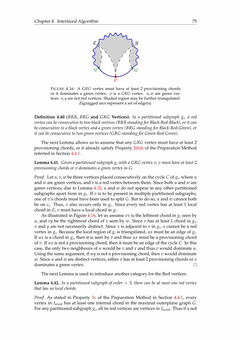
Chapter 4. Interlaced Algorithm 75
FIGURE 4.16: A GRG vertex must have at least 2 provisioning chordsor it dominates a green vertex. v is a GRG vertex. u, w are green ver-tices. x, y are not red vertices. Shaded region may be further triangulated.
Zigzagged arcs represent a set of edge(s).
Definition 4.40 (BRB, BRG and GRG Vertices). In a partitioned subgraph gi, a redvertex can be consecutive to two black vertices (BRB standing for Black-Red-Black), or it canbe consecutive to a black vertex and a green vertex (BRG standing for Black-Red-Green), orit can be consecutive to two green vertices (GRG standing for Green-Red-Green).
The next Lemma allows us to assume that any GRG vertex must have at least 2provisioning chords, or it already satisfy Property 2(b)ii of the Preparation Methodreferred in Section 4.4.1.
Lemma 4.41. Given a partitioned subgraph gi with a GRG vertex v, v must have at least 2provisioning chords or v dominates a green vertex in G.
Proof. Let u, v, w be three vertices placed consecutively on the cycle C of gi, where uand w are green vertices, and v is a red vertex between them. Since both u and w aregreen vertices, due to Lemma 4.32, u and w do not appear in any other partitionedsubgraphs apart from in gi. If v is to be present in multiple partitioned subgraphs,one of v’s chords must have been used to split G. But to do so, u and w cannot bothbe on ci. Thus, v also occurs only in gi. Since every red vertex has at least 1 localchord in G, v must have a local chord in gi.
As illustrated in Figure 4.16, let us assume vx is the leftmost chord in gi seen byu, and vy be the rightmost chord of v seen by w. Since v has at least 1 chord in gi,x and y are not necessarily distinct. Since x is adjacent to v in gi, x cannot be a redvertex in gi. Because the local region of gi is triangulated, ux must be an edge of gi.If ux is a chord in gi, then it is seen by v and thus ux must be a provisioning chordof v. If ux is not a provisioning chord, then it must be an edge of the cycle C. In thiscase, the only two neighbours of u would be v and x and thus v would dominate u.Using the same argument, if wy is not a provisioning chord, then v would dominatew. Since u and w are distinct vertices, either v has at least 2 provisioning chords or vdominates a green vertex.
The next Lemma is used to introduce another category for the Red vertices.
Lemma 4.42. In a partitioned subgraph of order > 3, there can be at most one red vertexthat has no local chords.
Proof. As stated in Property 1c of the Preparation Method in Section 4.4.1, everyvertex in Iavoid has at least one internal chord in the maximal outerplane graph G.For any partitioned subgraph gi, all its red vertices are vertices in Iavoid. Thus if a red

Chapter 4. Interlaced Algorithm 76
vertex u of gi does not have any internal chords in gi then it must be due to splittingthe graph along an edge uv where v is also a vertex in Iavoid.
Consider the Procedure GENERATESUBGRAPHS(G, Iavoid). Here g is a subgraphof G, such that g is in the process of being turned into a partitioned subgraph. Theprocedure has crossed an edge pq connecting two red vertices p and q. Furthermore,x is the vertex that sees pq where x is strictly in the explored part of the subgraph g.Since we are only considering partitioned subgraphs of order > 3, for g to producesuch a partitioned subgraph, g must have a higher order than 3 after split along pq.Then (x, p, q) cannot be the maximal cycle of g after the split. As a result, one of xpand xq must be a chord of g. In this case, notice that in Line 22–28 of the algorithm,it is always ensured that any time the graph is further split into smaller graphs, thered vertex that is kept in the (partially) explored graph g always consists of at leastone internal chord in it. Thus the only time a partitioned subgraph gnew can have ared vertex that does not contain any internal chord, is when gnew was split off alongpq from g. Thus there can be at most one red vertex with no internal chords in apartitioned subgraph.
Taking Lemma 4.42 in consideration we present the following definition.
Definition 4.43 (Priority Vertex). Given a partitioned subgraph gi of a maximal outer-plane graph G with the maximal empty cycle C, and a set of non-consecutive vertices Iavoidon C, if the order of gi is larger than 3, then it can have at most one red vertex with nointernal chords. Such a red vertex is called a priority vertex of gi. Any vertex of gi that isnot a priority vertex is called a non-priority vertex.
Due to Property 1c of the Preparation Method referred in Section 4.4.1, everyvertex in Iavoid has at least one local chord. Since a priority vertex does not haveany local chords in its respective partitioned subgraph, we can conclude that oneor more local chords of the priority vertex were used to split the graph into smallersubgraphs and thus any priority vertex must have at least one black vertex consec-utive to its partitioned subgraph’s maximal empty cycle. Thus a priority vertex canonly be of type BRB or BRG.
TABLE 4.1: Types of red vertices in partitioned subgraphsCase Priority Pattern A B C
1 No BRB 3 0 12 No BRG 2 1 13 No GRG 1 2 24 Yes BRB 2 1 15 Yes BRG 1 2 16 Yes GRG N/A N/A N/A
A: Minimum number of chords of the red vertex in G that are present as edges in gi.B: Maximum number of chords that are required for the red vertex.C: Minimum number of provisioning chords of the red vertex already present in gi.
Taking all this into consideration, in Table 4.1 we categorized a complete list of allthe possible types of red vertices that can arise in our partitioned subgraphs.4 Ev-ery avoiding vertex in G must contain at least 1 local chord. Column A refers tothe minimum number of chords in G of the said red vertex that must be present in
4An observant reader may realize that we already know how to deal with Case 1–4. Case 5 requiresa bit more work.

Chapter 4. Interlaced Algorithm 77
the partitioned subgraph gi as a chord or as an edge of its maximal empty cycle.Column B denotes the maximum number of chords that may be required for a redvertex of the given type to ensure that the vertex has at least 3 internal chords in theresulting graph G′′ := G〈Sprep〉. Finally Column C notes the minimum number ofprovisioning chords the red vertex may still require, unless it is already dominatinga green vertex due to Lemma 4.41 and Lemma 4.36.
Now let us describe each case in detail.
Case 1: Non-priority BRB vertex
Let u be a non-priority BRB vertex consecutive to two black vertices v and w on themaximal empty cycle of a partitioned subgraph gi of the maximal outerplane graphG. Because u is a red vertex and because v and w are black vertices, they must all bein Iavoid and thus they cannot be consecutive on G’s maximal empty cycle. Thus bothuv and uw must be chords of G. Furthermore, because u is not a priority vertex, umust have at least one local chord ux in gi. This chord ux along with uv and uw giveus the three chords u requires in G. Thus no additional chord is needed for u.
Case 2: Non-priority BRG vertex
Let u be a non-priority BRG vertex consecutive to a black vertex v and a green ver-tex w on the maximal empty cycle of the partitioned subgraph gi of the maximalouterplane graph G. Because u is a red vertex and because v is a black vertex, theymust both be in Iavoid and thus they cannot be consecutive on G’s maximal emptycycle. Thus uv must be a chord of G. Furthermore, because u is not a priority vertex,u must have at least one local chord ux in gi. This chord ux along with uv are twochords of u in G and by adding one more chord to be added in gi we can ensure thatu’s chord requirement is met.
Case 3: Non-priority GRG vertex
Let u be a non-priority GRG vertex consecutive to two green vertices v and w onthe maximal empty cycle of the partitioned subgraph gi of the maximal outerplanegraph G. Because both v and w are green vertices, neither uv nor uw can be a parti-tioning chord of G and thus v and w must be consecutive to u in G’s maximal emptycycle. Thus neither uv, nor uw is a chords of G. Furthermore, because u is not a pri-ority vertex, u must have at least one local chord ux in gi. This chord ux is the onlyknown chord of u in G. Thus u still requires 2 more chords to meet its requirement.From Lemma 4.41 we know that u would have at least 2 provisioning chords in gi,or u already dominates a green vertex.
Case 4: Priority BRB vertex
Let u be a priority BRB vertex consecutive to two black vertices v and w on the max-imal empty cycle of the partitioned subgraph gi of the maximal outerplane graph G.Because u is a red vertex and because v and w are black vertices, they must all be inIavoid and thus they cannot be consecutive in G’s maximal empty cycle. Thus both uvand uw are chords of G. Since u is a priority vertex, u does not have any local chordsin gi. Thus uv and uw are the 2 known chords u has in G, both of which are edgeson the maximal empty cycle of gi. Thus by adding one more chord of u in gi, we canguarantee that u’s degree requirement is met.
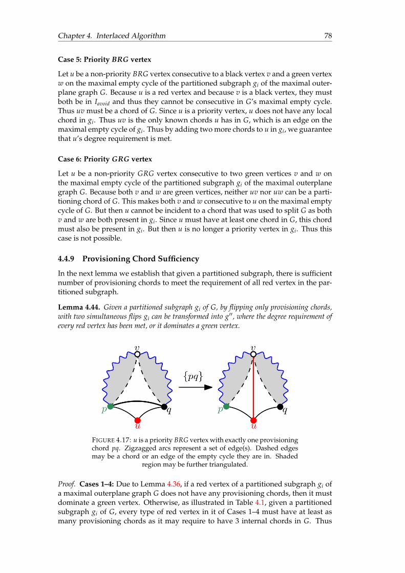
Chapter 4. Interlaced Algorithm 78
Case 5: Priority BRG vertex
Let u be a non-priority BRG vertex consecutive to a black vertex v and a green vertexw on the maximal empty cycle of the partitioned subgraph gi of the maximal outer-plane graph G. Because u is a red vertex and because v is a black vertex, they mustboth be in Iavoid and thus they cannot be consecutive in G’s maximal empty cycle.Thus uv must be a chord of G. Since u is a priority vertex, u does not have any localchord in gi. Thus uv is the only known chords u has in G, which is an edge on themaximal empty cycle of gi. Thus by adding two more chords to u in gi, we guaranteethat u’s degree requirement is met.
Case 6: Priority GRG vertex
Let u be a non-priority GRG vertex consecutive to two green vertices v and w onthe maximal empty cycle of the partitioned subgraph gi of the maximal outerplanegraph G. Because both v and w are green vertices, neither uv nor uw can be a parti-tioning chord of G. This makes both v and w consecutive to u on the maximal emptycycle of G. But then u cannot be incident to a chord that was used to split G as bothv and w are both present in gi. Since u must have at least one chord in G, this chordmust also be present in gi. But then u is no longer a priority vertex in gi. Thus thiscase is not possible.
4.4.9 Provisioning Chord Sufficiency
In the next lemma we establish that given a partitioned subgraph, there is sufficientnumber of provisioning chords to meet the requirement of all red vertex in the par-titioned subgraph.
Lemma 4.44. Given a partitioned subgraph gi of G, by flipping only provisioning chords,with two simultaneous flips gi can be transformed into g′′, where the degree requirement ofevery red vertex has been met, or it dominates a green vertex.
FIGURE 4.17: u is a priority BRG vertex with exactly one provisioningchord pq. Zigzagged arcs represent a set of edge(s). Dashed edgesmay be a chord or an edge of the empty cycle they are in. Shaded
region may be further triangulated.
Proof. Cases 1–4: Due to Lemma 4.36, if a red vertex of a partitioned subgraph gi ofa maximal outerplane graph G does not have any provisioning chords, then it mustdominate a green vertex. Otherwise, as illustrated in Table 4.1, given a partitionedsubgraph gi of G, every type of red vertex in it of Cases 1–4 must have at least asmany provisioning chords as it may require to have 3 internal chords in G. Thus
Chapter 4. Interlaced Algorithm 79
for these cases using Lemma 4.39 we can compute si := (si1 , si2) such that each redvertex of g′′i := gi〈si〉 has at least 3 incident internal chords or it dominates a greenvertex.
Case 5: A priority BRG vertex has exactly one provisioning chord, and no inci-dent chord in gi. Let u be a priority BRG vertex with a single provisioning chordpq (refer to Figure 4.17 left). Then pu and qu are edges of the maximal cycle ci of gi.WLOG let p be a green vertex and q be a black vertex and let the other vertex thatsees pq be v. We now consider two subcases—a. v is a red vertex and b. v is not ared vertex.
Case 5a: Vertex v is red: Since a partitioned subgraph can have only one priorityvertex, v can be a red vertex of three types: a non-priority BRB, BRG or GRG vertex.Due to Lemma 4.34 u and v cannot both be consecutive to q on ci, so qv must bea chord of gi. Furthermore, since v is a red vertex, neither pv nor qv can be provi-sioning chords in gi. Notice that if pv is not a chord in gi, then flipping pq makesboth u and v dominate the green vertex p. Thus if pv is not a chord, simply usingLemma 4.39 without having any preselected edges is sufficient for meeting the re-quirements for all red vertices in gi. So for the following subcases we assume bothpv and qv are chords of gi.
1. v is a non-priority BRB vertex: In this case both the edges on the maximalcycle ci incident to v are chords in G. Thus if the final graph gi〈si〉 containsat least 1 internal chord of v, it would meet the chord requirement of v. Thevertex u requires 2 internal chords in gi, so it would require one more chordafter flipping pq. Define the graph gi = gi〈pq〉 with the vertex v coloured asblack (refer to Figure 4.17 right).5 Then gi meets all requirements listed in Def-inition 4.27 to be a partitioned subgraph of G〈pq〉. Thus by using Lemma 4.39,we preselect exactly one (say pv) of these provisioning chords to be flipped inthe second simultaneous flip set si2 . The other of the two chords (say qv) ismarked as a non-provisioning chord so it is not inserted in si. Notice that sinceboth pv and qv are singly provisioning chord with u being their only avoidingvertex, not flipping qv does not affect the process of increasing degree of otherred vertices in the graph. Then we get an ordered set of simultaneously flip-pable sets si := (si1 , si2) that flips all the provisioning chords in gi (except qv).Since uv is not a provisioning chord of gi, uv must be present in the resultinggraph gi〈si〉. Since qv is not flipped, in the resulting graph v must have twochords uv and qv, meeting v’s degree requirement. Furthermore, flipping pqproduces an internal chords incident to u, which along with the chord uv en-sures that u has at least two chords. Thus the degree requirement of both u andv are met along with the degree requirement of all the red vertices in gi〈si〉.Now consider in the graph gi, si := (si1 ∪ pq, si2). Notice that neither of pq’sconsecutive edges pv and qv are in si1 . Thus si1 ∪ pq must be flippable in gi.Also notice that the resulting graph gi〈si1 ∪ pq〉 is the same as gi〈si1〉. Thus siis flippable in gi, and in the resulting graph gi〈si〉 the degree requirement bothu and v along with all the remaining red vertices are met or due to Lemma 4.36the vertex would dominate a green vertex.
5Notice that colouring v to black in gi means that Gp no longer has any partitioned subgraph wherev is red, violating Property 4 of Definition 4.27. This property is used to ensure that so long all redvertices meet their degree requirement, or they dominate a vertex not in Iavoid, so do all avoidingvertices in Iavoid. Since we explicitly show that v meets its degree requirement, the violation of thisproperty is inconsequential.
Chapter 4. Interlaced Algorithm 80
2. v is a non-priority BRG vertex: In this case if in the final graph gi〈si〉, the ver-tices u is incident to 2 and v is incident to 1 internal chord, then their degreerequirement would be met. By following the exact same steps as in Case 5b.1we compute an ordered set of flippable edge sets si in gi. Then notice that ingi〈si〉, u and v have at least 2 and 1 chord respectively. Thus in gi〈si〉 require-ments of all the red vertices (including u and v) are met or due to Lemma 4.36the red vertex dominates a green vertex.
3. v is a non-priority GRG vertex: We see from Table 4.1 that the maximumnumber internal chords required by both u and v in gi is 2. Define the graphgi = gi〈pq〉 with the vertex v (refer to Figure 4.17 left). Since both u andv are red vertices and they are neighbours, gi is not a partitioned subgraph.Now we split gi along uv and get two maximal outerplane graphs gl and gr
defined by the cycles (yuv, vu) and (
yvu, uv) respectively. We colour u red and v
black in gl , and colour these two vertices in reverse in gr. Finally, we define uas the priority vertex of gl . Since qv is a chord in gr, gr has no priority vertex.Notice that both the consecutive vertices of v on the maximal cycle of gi aregreen and as a result both gl and gr must have at least one green vertex each.Furthermore, since gi is a partitioned subgraph, and gl and gr are created bysplitting gi, these two graphs meet all requirements listed in Definition 4.27 tobe a partitioned subgraph of G〈pq〉.In the partitioned subgraph gl , preselect the provisioning chord pv to be flippedon the second simultaneous flip. Then using Lemma 4.39, we compute the or-dered set of simultaneously flippable edge sets sl and sr of the graphs gl and glrespectively, and define si := (sl ∪ sr).6 Then si flips all the provisioning chordsof both gl and gr. The chord qv in gr is not a provisioning chord in gr and thusit cannot be in si. So just as Case 5b.1 neither of pq’s consecutive edges pv andqv are in si1 . Thus si1 ∪ pqmust be flippable in gi. Observe that the resultinggraph gi〈si1 ∪ pq〉 is the same as gi〈si1〉. Thus si := (si1 ∪ pq, si2) is flip-pable in gi, and in the resulting graph gi〈si〉 the degree requirement of all thered vertices are met or due to Lemma 4.36 the vertex would dominate a greenvertex.
Case 5b: Vertex v is not red: This case is similar to Case 5a1. Except since v isnot a red vertex, we do not need to recolour v to black. We define the graph gi =gi〈pq〉. Using the same argument as before, gi must be a partitioned subgraph ofG〈pq〉. So we compute si and using it compute si, as shown in Case 5a1. Then si isflippable in gi, and in the resulting graph gi〈si〉 the degree requirement of all the redvertices are met or due to Lemma 4.36 the vertex would dominate a green vertex.
Thus every possible cases for computing si := (si1 , si2) to sufficiently processingthe red vertices in gi has been handled—completing the proof of this lemma.
Recall that the Preparation Method Property 2c requires that no two single pro-visioning chord of the same avoiding vertex can both be in Sprep1 . The next lemmasatisfies all the output properties of the Preparation Method.
Lemma 4.45. Given a maximal outerplane graph G and a set on non-consecutive ver-tices Iavoid on its maximal cycle C, an ordered set of two simultaneous flip sets Sprep :=(Sprep1 , Sprep2) can be computed, such that the graph G〈Sprep〉 satisfies the following prop-erties:
6The method to compute the union of two ordered set of edge sets is defined in Definition 4.1.
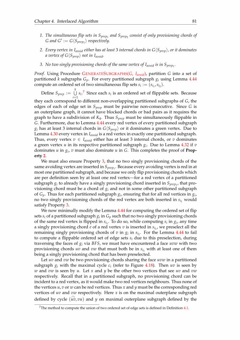
Chapter 4. Interlaced Algorithm 81
1. The simultaneous flip sets in Sprep1 and Sprep2 consist of only provisioning chords ofG and G′ := G〈Sprep1〉 respectively.
2. Every vertex in Iavoid either has at least 3 internal chords in G〈Sprep〉, or it dominatesa vertex of G〈Sprep〉 not in Iavoid.
3. No two singly provisioning chords of the same vertex of Iavoid is in Sprep1 .
Proof. Using Procedure GENERATESUBGRAPHS(G, Iavoid), partition G into a set ofpartitioned k subgraphs Gp. For every partitioned subgraph gi using Lemma 4.44compute an ordered set of two simultaneous flip sets si := (si1 , si2).
Define Sprep :=k⋃
i=1si.7 Since each si is an ordered set of flippable sets. Because
they each correspond to different non-overlapping partitioned subgraphs of G, theedges of each of edge set in Sprep must be pairwise non-consecutive. Since G isan outerplane graph, it cannot have blocked chords or bad pairs as it requires thegraph to have a subdivision of K4. Thus Sprep must be simultaneously flippable inG. Furthermore, due to Lemma 4.44 every red vertex of every partitioned subgraphgi has at least 3 internal chords in G〈Sprep〉 or it dominates a green vertex. Due toLemma 4.30 every vertex in Iavoid is a red vertex in exactly one partitioned subgraph.Thus, every vertex v ∈ Iavoid either has at least 3 internal chords, or v dominatesa green vertex u in its respective partitioned subgraph gi. Due to Lemma 4.32 if vdominates u in gi, v must also dominate u in G. This completes the proof of Prop-erty 2.
We must also ensure Property 3, that no two singly provisioning chords of thesame avoiding vertex are inserted in Sprep1 . Because every avoiding vertex is red in atmost one partitioned subgraph, and because we only flip provisioning chords whichare per definition seen by at least one red vertex—for a red vertex of a partitionedsubgraph gi to already have a singly provisioning chord inserted in Sprep1 , that pro-visioning chord must be a chord of gi and not in some other partitioned subgraphof Gp. Thus for each partitioned subgraph gi, ensuring that for all red vertices in gi,no two singly provisioning chords of the red vertex are both inserted in si1 wouldsatisfy Property 3.
We now minimally modify the Lemma 4.44 for computing the ordered set of flipsets si of a partitioned subgraph gi in Gp such that no two singly provisioning chordsof the same red vertex is flipped in si1 . To do so, while computing si in gi, any timea singly provisioning chord e of a red vertex v is inserted in si1 , we preselect all theremaining singly provisioning chords of v in gi in si2 . For the Lemma 4.44 to failto compute a flippable ordered set of edge sets si due to this preselection, duringtraversing the faces of gi via BFS, we must have encountered a face uvw with twoprovisioning chords uv and vw that must both be in si1 with at least one of thembeing a singly provisioning chord that has been preselected.
Let uv and vw be two provisioning chords sharing the face uvw in a partitionedsubgraph gi with the maximal cycle ci (refer to Figure 4.18). Then uv is seen byw and vw is seen by u. Let x and y be the other two vertices that see uv and vwrespectively. Recall that in a partitioned subgraph, no provisioning chord can beincident to a red vertex, as it would make two red vertices neighbours. Thus none ofthe vertices u, v or w can be red vertices. Thus x and y must be the corresponding redvertices of uv and vw respectively. Here x is on the maximal outerplane subgraphdefined by cycle (
yuv, vu) and y on maximal outerplane subgraph defined by the
7The method to compute the union of two ordered set of edge sets is defined in Definition 4.1.
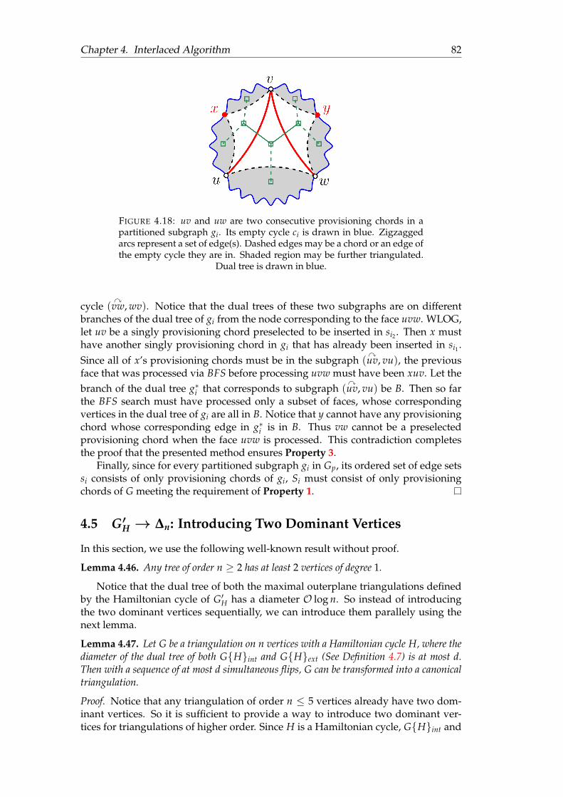
Chapter 4. Interlaced Algorithm 82
FIGURE 4.18: uv and uw are two consecutive provisioning chords in apartitioned subgraph gi. Its empty cycle ci is drawn in blue. Zigzaggedarcs represent a set of edge(s). Dashed edges may be a chord or an edge ofthe empty cycle they are in. Shaded region may be further triangulated.
Dual tree is drawn in blue.
cycle (yvw, wv). Notice that the dual trees of these two subgraphs are on different
branches of the dual tree of gi from the node corresponding to the face uvw. WLOG,let uv be a singly provisioning chord preselected to be inserted in si2 . Then x musthave another singly provisioning chord in gi that has already been inserted in si1 .Since all of x’s provisioning chords must be in the subgraph (
yuv, vu), the previous
face that was processed via BFS before processing uvw must have been xuv. Let thebranch of the dual tree g∗i that corresponds to subgraph (
yuv, vu) be B. Then so far
the BFS search must have processed only a subset of faces, whose correspondingvertices in the dual tree of gi are all in B. Notice that y cannot have any provisioningchord whose corresponding edge in g∗i is in B. Thus vw cannot be a preselectedprovisioning chord when the face uvw is processed. This contradiction completesthe proof that the presented method ensures Property 3.
Finally, since for every partitioned subgraph gi in Gp, its ordered set of edge setssi consists of only provisioning chords of gi, Si must consist of only provisioningchords of G meeting the requirement of Property 1.
4.5 G′H → ∆n: Introducing Two Dominant Vertices
In this section, we use the following well-known result without proof.
Lemma 4.46. Any tree of order n ≥ 2 has at least 2 vertices of degree 1.
Notice that the dual tree of both the maximal outerplane triangulations definedby the Hamiltonian cycle of G′H has a diameter O log n. So instead of introducingthe two dominant vertices sequentially, we can introduce them parallely using thenext lemma.
Lemma 4.47. Let G be a triangulation on n vertices with a Hamiltonian cycle H, where thediameter of the dual tree of both GHint and GHext (See Definition 4.7) is at most d.Then with a sequence of at most d simultaneous flips, G can be transformed into a canonicaltriangulation.
Proof. Notice that any triangulation of order n ≤ 5 vertices already have two dom-inant vertices. So it is sufficient to provide a way to introduce two dominant ver-tices for triangulations of higher order. Since H is a Hamiltonian cycle, GHint and
Chapter 4. Interlaced Algorithm 83
GHext must be maximal outerplane graphs. Let their corresponding empty cyclesbe Cint and Cext. Due to Lemma 4.46 the dual tree of both GHint and GHextmust each have at least 2 leaf nodes. Thus, both Cext and Cint must have at least 2foreign 2-chords in G, each with an avoiding vertex. Let u be an avoiding vertex ofCint and v be an avoiding vertices of Cext. Because the graph is simple, u and v mustbe distinct.
We define Gu := GHint and Gv := GHext \ u with their correspondingmaximal empty cycle being Cu and Cv respectively. Notice that Gu and Gv are bothmaximal outerplane graphs. Thus using Lemma 2.65 we can compute two orderedsets of simultaneous flip set Su and Sv which would make u and v dominant ver-tex in their corresponding maximal outerplane subgraphs Gu and Gv, where both|Su|, |Sv| ≤ d. Set S := Su ∪ Sv.
We now prove the flippability of S in G.
• Non-consecutivity: Every edge of Su is in the interior of H and every edge ofSv is in the exterior of H. Thus no edge of Su can be consecutive to an edge ofSv. Thus edges of S must be pairwise non-consecutive.
• Bad pair: For two edges to form a bad pair, they must be seen by the same pairof vertices. As we flip each simultaneous flip set in Su in sequence, each chordof the next simultaneous flip set in Su is seen by u. Since u is not in Cv, none ofthe edges in Sv can be seen by u. Thus for any flip set in S, no two of its edgescan form a bad pair.
• No blocked edge: Due to Lemma 2.38, each chord of Gu and Gv is (individu-ally) flippable in their respective subgraphs. Thus for any edge in Su or Sv tobe blocked, it must be blocked by a foreign chord of Cu and Cv respectively.Furthermore, since every edge of Su when flipped, produces an edge incidentto u, this blocking chord must be a foreign chord of Cu incident to u. Similarly,for any edge of Sv to be blocked, v must be incident to a foreign chord of Cv.Observe that u and v are avoiding vertices of Cint and Cext respectively. Thenneither u, nor v can have any foreign chords of Cint and Cext respectively. Thuswhen the edge sets in S are flipped in sequence, none of these the edges can beblocked in G.
Thus due to Lemma 2.50 the ordered set of edge sets S must be flippable in Gand in the resulting graph ∆n u and v are two dominant vertices. Finally |S| =max(|Su|, |Sv|) ≤ d. Thus with a sequence of at most d simultaneous flips, G shall betransformed into the canonical triangulation ∆n.
4.6 Complexity Analysis for the Interlaced Algorithm
We compute the complexity of the Interlaced Algorithm, by evaluating the complex-ity of each of the steps mentioned in Section 4.1.
G1 → GH : Transforming Into Hamiltonian Triangulation
Bose et al. (2007) proved that with a single simultaneous flip any triangulation G1can be transformed into a Hamiltonian triangulation GH with a Hamiltonian cycleH.
Chapter 4. Interlaced Algorithm 84
GH → G′H : Transformation to Logarithmic Diameter
Once we have the Hamiltonian triangulation GH, we use the Interlaced algorithmon GH arbitrarily defining G1
ear := GHint and G1prep := GHext.
On the first iteration, G1 is transformed into G2 where the diameter of the dualtree of G2
prep is exactly 2 less than that of G1ear maintaining the requirements specified
in Lemma 3.12 between G1ear and G2
prep. Furthermore, the order of G2prep is at most 11
12times the order of G1
ear.On each subsequent iteration of the algorithm where i > 1, with 2 simultaneous
flip Gi is transformed into Gi+1 where the diameter of the dual tree of Gi+1prep is exactly
2 less than that of Giear. Furthermore, the order of Gi+1
prep is at most 56 times the order of
Giear. This process also satisfies the requirements specified in Lemma 3.12 between
Giear and Gi+1
prep. Notice that on the even iterations the interlaced algorithm createsears in GHint, and in the odd iterations the algorithm creates ears in GHext.Thus using Lemma 3.12, no more than 2× 2 log n
log 65
simultaneous flips are required to
transform GH into G′H, where the diameter of the dual tree of both GHint andGHext are at most 2 log n
log 65
.
Thus the total number of simultaneous flips required including the first iterationis at most 4 log n
log 65+ 2
We now show how to remove the additional +2 constant from this complexityterm. Due to Lemma 4.46 any maximal outerplane graph with n > 3 vertices musthave at least 2 ears. By removing at least 2 ears on each iteration, no more than 5iterations are required (instead of 2 log 12
log 65
iterations) to reduce an outerplane graph
with n ≤ 12 vertices to 3 or less vertices. Thus the total number of simultaneousflips (including the first iteration) required would be at most:
4 log nlog 6
5
+ max
2 + 5− 2 log 12
log 65
, 0
≤ 4
log 65
log n
Here inside the max function, the term 2 is for the first iteration, and the term(5− 2 log 12
log 65) is obtained by using Lemma 4.46.
G′H → ∆n: Introducing Two Dominant Vertices
Since the diameter of the dual tree of G′H is at most 4log 6
5log n, using Lemma 4.47,
with no more than another 4log 6
5log n simultaneous flips, G′H can be transformed
into a canonical triangulation ∆n.
∆n → G2: Do the Reverse to Transform ∆n to Target Triangulation
As explained in Section 2.4.8, sequence of simultaneous flips are reversible. Thuswe can convert ∆n to G2 with the same number of simultaneous flips required totransform G2 to ∆n.
Theorem 4.48. Let G1 and G2 be two triangulations on n vertices. There is a sequence of nomore than c log n + 2 simultaneous flips to transform G1 into G2, where c = 12
log 65≈ 45.6.
Proof. The number of simultaneous flips required to do the following is:
1. G1 → GH: A single simultaneous flip is required.
Chapter 4. Interlaced Algorithm 85
2. GH → G′H: At most 4log 6
5log n simultaneous flips are required.
3. G′H → ∆n: At most 2log 6
5log n simultaneous flips are required.
4. ∆n → G2: This is the same as the sum-total of the previous 3 steps. Thus nomore than 6
log 65
log n + 1 simultaneous flips are required.
Total number of simultaneous flips required:
2×(
6log 6
5
log n + 1
)=
12log 6
5
log n + 2
Thus with no more than c log n simultaneous flips G1 can be transformed into G2,where c = 12
log 65.
86
Chapter 5
Conclusion
In this thesis, we have considered the problem of transforming any triangulation intoany other triangulation of equal order via a sequence of simultaneous flips. Bose etal. (2007) discovered an algorithm for solving the problem requiring no more than4(
2log 54
53+ 2
log 65
)log n + 2 ≈ 327.1 log n + 2 simultaneous flips. The bottleneck of
this algorithm is the transformation of the two maximal outerplane graphs GHintand GHext of a Hamiltonian triangulation GH with a selected Hamiltonian cycleH, so that for the resulting graph G′H, diameters of the dual trees of both G′Hintand G′Hext are O(log n), where n is the number of vertices. To achieve this, foreach of these maximal outerplane triangulations, the authors broke down the pro-cess into a set of iterations consisting of 2 simultaneous flips each. In each iteration,an independent set of vertices I of size at least n/6 is selected where each vertex hasat most 2 local chords. The more of these vertices can be made into ears in the re-spective maximal outerplane subgraphs, by flipping their incident local chords, thefewer number of simultaneous flips will be required to make the diameter O(log n)of the dual tree of the resulting maximal outerplane graphs. At the worst-case, thealgorithm of Bose et al. (2007) ensures only n/54 ears per iteration. The major con-tribution of this thesis is in addressing this bottleneck of the algorithm. In Chapter 3we ensured that after the first simultaneous flip of each iteration, each vertex in I hasa degree at most 3. This, along with a few other improvements lead to guaranteeingat least n/12 ears to be produced in each iteration. In Chapter 4 we ensured that,after the second simultaneous flip of each iteration, each vertex in I has a degree atmost 2. This guarantees at least n/6 ears to be produced in each iteration.
In Chapter 3 we have modified this algorithm to reduce its complexity to4(
2log 12
11+ 2
log 97
)log n + 2 ≈ 85.8 log n + 2 simultaneous diagonal flips. To achieve
this, we have improved the complexity of transforming both the maximal outerplanesubgraphs defined by a Hamiltonian cycle of a triangulation into another whosedual tree is of diameter O(log n). The following two properties of triangulations,established in this thesis, have been crucial in the improvement of Bose et al. (2007)algorithm.
1. No two consecutive local chords of an empty cycle can be both blocked.(see Lemma 3.3)
2. No three blocking foreign chords of an empty cycle can share a face.(see Lemma 3.5)
We also showed that to make the diameter of the dual tree of an outerplane graphO(log n) with O(log n) simultaneous flips, the independent set I5 yields better re-sults than the independent set I4. Here Id denotes a set of independent vertices, noneof which has a degree greater than d.
Chapter 5. Conclusion 87
In Chapter 4 we introduced a novel algorithm that further improves the upperbound for transforming triangulations via simultaneous flips. In this new approach,while the interlaced algorithm creates ears in one of the maximal outerplane graphsbetween GHint and GHext, it simultaneously preprocesses the other maximalouterplane graph. As a result of this preprocessing, a larger number of ears are guar-anteed to be introduced in it on the next iteration. The process is repeated until thediameter of the dual tree of both the maximal outerplane graphs become logarith-mic to their order. Next, by introducing the two dominant vertices simultaneouslyinstead of one after the other, we further reduced the upper bound for transforminga triangulation to a canonical triangulation, and hence to any other triangulation.This has resulted in requiring no more than 12
log 65
log n + 2 ≈ 45.6 log n + 2 simulta-
neous flips to transform any triangulation to any other of equal order.We must also mention that during modification of the algorithm we have taken
the course of transforming one triangulation into another via canonical triangula-tion, which is not necessarily optimal. There may be shortcuts in transforming onetriangulation into another without ever passing through the canonical triangulation.
5.1 Open Problems
During this research we felt that the following problems related to diagonal flippingare worth exploring.
1. A triangulation G is given with an empty cycle C, and a set of non-consecutivevertices I on C with degree at most 4 in the maximal outerplane subgraphGC. Using no more than 2 simultaneous flips, what is the largest ratio of thevertices in I whose degree can be reduced to 2 in GC? This is the inverse ofwhat is done in our preparation method. (See Section 4.4)
2. Can a more elegant method or proof be introduced for the Preparation Methodin Section 4.4?
3. Is it possible to improve the complexity of the interlaced algorithm in Chap-ter 4 by making the diameter of the dual tree of the two maximal outerplanesubgraphs logarithmic to the graph’s order more efficiently? One possibility isto use a larger number of simultaneous flips per iteration to create ears out of alarger set of independent vertices Id, where each vertex has a degree at most d.
4. From Section 3.2, we know that I5 is optimal for transforming a maximal out-erplane graph into one whose dual tree is logarithmic in diameter to its size.Does such a Preparation Method exist that allows the technique introducedin Theorem 3.13 to be applied directly in a Hamiltonian triangulation? Thiswould produce the optimal version of the interlaced algorithm.

88
Bibliography
Beauchamps, D Gouyou (1978). “Un algorithme de recherche de circuits Hamil-toniens dans les graphes 4-connexes planaires”. In: Problemes Combinatoires etTheorie des Graphes (CNRS, Paris, 1978), pp. 185–187.
Biedl, Therese C, Prosenjit Bose, Erik D Demaine, and Anna Lubiw (2001). “Effi-cient algorithms for Petersen’s matching theorem”. In: Journal of Algorithms 38.1,pp. 110–134.
Bose, Prosenjit, Vida Dujmovic, and David R Wood (2005). “Induced subgraphs ofbounded degree and bounded treewidth”. In: International Workshop on Graph-Theoretic Concepts in Computer Science. Springer, pp. 175–186.
Bose, Prosenjit and Ferran Hurtado (2009). “Flips in planar graphs”. In: Computa-tional Geometry 42.1, pp. 60–80.
Bose, Prosenjit and Sander Verdonschot (2011). “A history of flips in combinatorialtriangulations”. In: Spanish Meeting on Computational Geometry. Springer, pp. 29–44.
Bose, Prosenjit, Jurek Czyzowicz, Zhicheng Gao, Pat Morin, and David R Wood(2007). “Simultaneous diagonal flips in plane triangulations”. In: Journal of GraphTheory 54.4, pp. 307–330.
Bose, Prosenjit, Dana Jansens, André Van Renssen, Maria Saumell, and Sander Ver-donschot (2014). “Making triangulations 4-connected using flips”. In: Computa-tional Geometry 47.2, pp. 187–197.
Brunet, Richard, Atsuhiro Nakamoto, and Seiya Negami (1996). “Diagonal flips oftriangulations on closed surfaces preserving specified properties”. In: Journal ofCombinatorial Theory, Series B 68.2, pp. 295–309.
Cardinal, Jean, Michael Hoffmann, Vincent Kusters, Csaba D Tóth, and Manuel Wettstein(2018). “Arc diagrams, flip distances, and Hamiltonian triangulations”. In: Com-putational Geometry 68, pp. 206–225.
Chartrand, Gary and Frank Harary (1967). “Planar permutation graphs”. In: Annalesde l’IHP Probabilités et statistiques. Vol. 3. 4, pp. 433–438.
Chen, Yen-Ju, Jou-Ming Chang, and Yue-Li Wang (2005). “An efficient algorithm forestimating rotation distance between two binary trees”. In: International Journalof Computer Mathematics 82.9, pp. 1095–1106.
Chiba, Norishige and Takao Nishizeki (1989). “The hamiltonian cycle problem islinear-time solvable for 4-connected planar graphs”. In: Journal of Algorithms 10.2,pp. 187–211.
Cortés, Carmen, Clara Grima, Alberto Marquez, and Atsuhiro Nakamoto (2002).“Diagonal flips in outer-triangulations on closed surfaces”. In: Discrete mathemat-ics 254.1-3, pp. 63–74.
Frati, Fabrizio (2015). “A lower bound on the diameter of the flip graph”. In: arXivpreprint arXiv:1508.03473.
Galtier, Jerôme, Ferran Hurtado, Marc Noy, Stéphane Pérennes, and Jorge Urrutia(2003). “Simultaneous edge flipping in triangulations”. In: International Journal ofComputational Geometry & Applications 13.02, pp. 113–133.
BIBLIOGRAPHY 89
Gao, Zhicheng, Jorge Urrutia, and Jianyu Wang (2001). “Diagonal flips in labelledplanar triangulations”. In: Graphs and Combinatorics 17.4, pp. 647–657.
Hurtado, Ferran, Marc Noy, and Jorge Urrutia (1999). “Flipping edges in triangula-tions”. In: Discrete & Computational Geometry 22.3, pp. 333–346.
Komuro, Hideo (1997). “The diagonal flips of triangulations on the sphere”. In: Yoko-hama Math 44 (2), pp. 115–122.
Kuratowski, Casimir (1930). “Sur le probleme des courbes gauches en topologie”. In:Fundamenta mathematicae 15.1, pp. 271–283.
Lubiw, Anna and Vinayak Pathak (2015). “Flip distance between two triangulationsof a point set is NP-complete”. In: Computational Geometry 49, pp. 17–23.
Mori, Ryuichi, Atsuhiro Nakamoto, and Katsuhiro Ota (2003). “Diagonal flips inHamiltonian triangulations on the sphere”. In: Graphs and Combinatorics 19.3,pp. 413–418.
Nakamoto, Atsuhiro (1996). “Diagonal transformations in quadrangulations of sur-faces”. In: Journal of Graph Theory 21.3, pp. 289–299.
Negami, Seiya and Atsuhiro Nakamoto (1993). “Diagonal transformations of graphson closed surfaces”. In: Sci. Rep. Yokohama Nat. Univ. Sect. I Math. Phys.Chem. 40,pp. 71–97.
Pallo, Jean (1987). “On the rotation distance in the lattice of binary trees”. In: Infor-mation Processing Letters 25.6, pp. 369–373.
— (2000). “An efficient upper bound of the rotation distance of binary trees”. In:Information Processing Letters 73.3-4, pp. 87–92.
Petersen, Julius (1891). “Die Theorie der regulären graphs”. In: Acta Mathematica15.1, pp. 193–220.
Robertson, Neil, Daniel Sanders, Paul Seymour, and Robin Thomas (1997). “Thefour-colour theorem”. In: Journal of Combinatorial Theory, Series B 70.1, pp. 2–44.
Sleator, Daniel D, Robert E Tarjan, and William P Thurston (1988). “Rotation dis-tance, triangulations, and hyperbolic geometry”. In: Journal of the American Math-ematical Society 1.3, pp. 647–681.
Souvaine, Diane L, Csaba D Tóth, and Andrew Winslow (2011). “Simultaneouslyflippable edges in triangulations”. In: Spanish Meeting on Computational Geometry.Springer, pp. 138–145.
Wagner, K (1936). “Bemerkungen zum Vierfarbenproblem. Jahresber. Math”. In: Deutsch.Math.-Verein. 46, pp. 26–32.
Whitney, Hassler (1931). “A theorem on graphs”. In: Annals of Mathematics, pp. 378–390.

90
Alphabetical Index
chord, 8k-chord, 462-chord, 46bad chord, 32blocked chord, 32blocking chord, 32earing chord, 48external chord, 8foreign chord, 46internal chord, 8local chord, 46provisioning chord, 48, 64
doubly provisioning chord, 48,64
singly provisioning chord, 48,64
component, connected component, 21corner vertex, 48cycle, 8
k-cycle, 8empty cycle, 21
foreign region, 21local region, 21non-overlapping empty cycles,
46non-overlapping maximal
outerplane subgraphs, 46Hamiltonian cycle, 8maximal cycle, 8
ear, 22edge, 6
bad pair, 16blocked edge, 17blocking edge, 17bridge, 21consecutive edges, 16loop, 6, 90parallel edges, 6
face, 8flip, diagonal flip, 9
canonical triangulation, 6, 10
ordered set of flippable sets, 46seeing, 9sequence of flips, 9simultaneously flippable set, 16standard triangulation, 10
flip, flippable edge, 9
graph, 6k-connected, 8k-regular graph, 21combinatorial embedding, 8
equivalence class, 8outerface, 8, 11rotation system, 8
complete bipartite graph, 7complete graph, 6connected graph, 7dual graph, 21edge induced subgraph, 6edge subdivision, 7flip graph, 12graph subdivision, 7Hamiltonian triangulation, 12induced subgraph, 6isomorphism, 9maximal outerplanar graph, 9maximal outerplane graph, 9order of a graph, 6outerplanar graph, 8outerplane graph, 8partitioned subgraph, 63planar graph, 7plane graph, 7simple graph, 6subgraph, 6
external subgraph, 47internal subgraph, 47
supergraph, 6triangulation, 8
matching, 22perfect matching, 22
ALPHABETICAL INDEX 91
neighbourhood, 48closed neighbourhood, 48
path, 7arc, 32chord-path, 47
region, 8
separating triangle, 14
tree, 8branch, 73dual tree, 21, 22forest, 35leaf, 22unary tree, 35
used notationsG〈S〉, 16, 46GC, 25, 47GCext, 47GCint, 47NG(v), NG[v], 48[ypq], (
ypq), 32
degG(v), deg(v), 6
ext(C), 8int(C), 8union of ordered set of flippable
sets S1 ∪ S2, 46
vertex, 6BRB vertex, 75BRG vertex, 75GRG vertex, 75adjacent vertex, 6avoiding vertex, 46, 48, 64avoiding vertex set, 44, 46avoiding vertices, 63black vertex, 64degree of a vertex, 6dominant vertex, 10dominating vertex, 48earing vertex, 48earing vertex set, 48green vertex, 64independent set, 22non-priority vertex, 76priority vertex, 76red vertex, 64


![Taut ideal triangulations of 3–manifolds · Taut ideal triangulations are closely related to angled ideal triangulations, de-fined and studied by Casson, and developed in [4].](https://static.fdocuments.in/doc/165x107/5f93006a3be63401832bb150/taut-ideal-triangulations-of-3amanifolds-taut-ideal-triangulations-are-closely.jpg)