Trans-Cal Industries, Inc. - Dallas Avionics Industries, Inc. ... DO-160E lightning induced ......
26
Trans-Cal Industries, Inc. Model IA-RS232C-S Interface Adapter (Serializer) Owner/Installation Manual TSO-C88a Approved Trans-Cal Industries, Inc. 16141 Cohasset Street Van Nuys, CA 91406-2908 (818) 787-1221 (800) 423-2913 fax (818) 787-8916 www.trans-cal.com 19 July 2012 Document Number: 950000 Rev. F
Transcript of Trans-Cal Industries, Inc. - Dallas Avionics Industries, Inc. ... DO-160E lightning induced ......

Trans-Cal Industries, Inc.
Model IA-RS232C-S Interface Adapter (Serializer)
Owner/Installation Manual TSO-C88a Approved
Trans-Cal Industries, Inc. 16141 Cohasset Street
Van Nuys, CA 91406-2908 (818) 787-1221 (800) 423-2913 fax (818) 787-8916
www.trans-cal.com
19 July 2012 Document Number: 950000 Rev. F

Page 2 of 26
Copyright This document may not be reproduced, transmitted, or copied in any form without the prior written consent of Trans-Cal Industries, Inc. The data contained herein is subject to change without notice. Trans-Cal Industries hereby grants permission to download one copy of this manual and any subsequent revision, provided that electronic or printed copy contains this complete copyright notice. Trans-Cal Industries explicitly prohibits any unauthorized commercial distribution of this manual or any revision thereto. © 2012 by Trans-Cal Industries, Inc. 16141 Cohasset Street Van Nuys, CA 91406-2908 818/787-1221 800/423-2913 x400 Tech Support FAX 818/787-8916 E-Mail: [email protected] www.trans-cal.com Please Note: It is the responsibility of the installer of this equipment, within a specified type or class of aircraft, to determine that the aircraft operating conditions are within TSO standards. DO-160E lightning induced transient susceptibility tests were not conducted on this device and it is the responsibility of the installing agency to substantiate compliance with FAR25.1316. Advisory Circular AC20-136A provides guidance related to the protection of aircraft electrical systems from the effects of lightning. What’s in the Box:
Qty. Part Number Description 1 ea. IA-RS232C-S Interface Adapter 1 ea. 950000 Owner/Installation Manual 1 ea. DA-15S 15 Pin D-Subminiature Mating Receptacle 1 ea. DA-15P 15 Pin D-Subminiature Plug 2 ea. 600016 15 Pin Connector Back Shell 1 ea. DE-9P 9 Pin D-Subminiature Mating Plug 1 ea. 600017 9 Pin Connector Back Shell
History of Revision
Revision Date Description A 17 Apr. 2001 Revised in entirety. B 4 Apr. 2002 Added Tables I thru VII. C 18 Mar. 2004 Added Rev. A of 930003. D 25 Aug. 2004 Updated Manual E 25 Aug. 2006 Updated Manual chngd warranty from 40 to 42 months. F 19 July 2012 Corrected protocol listing, corrected connection diagram.

Page 3 of 26
Table of Contents
Abbreviations, Acronyms and Symbols .................................................................................... 4 Section 1.0 General .................................................................................................................... 5
1.1 Scope .................................................................................................................................. 5 1.2 Equipment Description .................................................................................................... 5 1.3 General Specifications ...................................................................................................... 5
1.3.1 Operating Voltage: ..................................................................................................... 5 1.3.2 Operating Current: ..................................................................................................... 5 1.3.3 Operating Temperature: ............................................................................................ 5 1.3.4 Storage Temperature: ............................................................................................... 5 1.3.5 Warm-up Time: ........................................................................................................... 5 1.3.6 Weight: ......................................................................................................................... 5 1.3.7 Operating Altitude: ..................................................................................................... 6 1.3.8 Accuracy: ..................................................................................................................... 6 1.3.9 Mechanical Characteristics: ...................................................................................... 6 1.3.10 Environmental: .......................................................................................................... 6
1.4 Parallel Altitude Data Input Port Specification (DA-15S Connector) ......................... 6 1.5 Parallel Altitude Data Output Port Specification ( DA-15P Connector) ..................... 7 1.6 Serial Altitude Data Output Port Specification (DE-9S Connector) ........................... 7 1.7 Serial Communication Format ......................................................................................... 7 1.8 Serial Communication Protocol ....................................................................................... 8
Section 2.0 Operation .................................................................................................................. 9 2.1 General ................................................................................................................................ 9 2.2 Operating Instructions ....................................................................................................... 9
Section 3.0 Installation and Calibration .................................................................................. 10 3.1 Mechanical Installation ................................................................................................... 10 3.2 Electrical Installation ....................................................................................................... 10 3.3 Serial Data Port Test Equipment .................................................................................. 13 3.4 Parallel Altitude Data Port Test Equipment ................................................................. 13
Section 4.0 Instructions for Continued Airworthiness ........................................................... 13 Section 5.0 Tables I through XII Digitizer Interconnection .................................................. 14
Table I Bendix/King ................................................................................................................ 14 Table II Cessna, Narco, Microair ......................................................................................... 15 Table III Garmin ...................................................................................................................... 16 Table IV Garmin ..................................................................................................................... 17 Table V Edo-Air, Genave, Collins, Radair .......................................................................... 18 Table VI Bendix, Wilcox, UPS AT ........................................................................................ 19
Serial Data Connector and Protocol Tables .......................................................................... 20 GPS Connection Data ............................................................................................................... 21 Outline Drawing .......................................................................................................................... 24 WARRANTY REGISTRATION................................................................................................. 26

Page 4 of 26
Abbreviations, Acronyms and Symbols
A Amperes AC Advisory Circular ARINC Aeronautical Radio Incorporated ASCII American Standard for Coded Information Interchange ATCRBS Air Traffic Control Radar Beacon System bps Bits per second. C
R Carriage Return EASA European Aviation Safety Agency EEPROM Electronically Erasable Read Only Memory EIA Electronic Industries Association ETSO European Technical Standard Order FAA Federal Aviation Administration FAR Federal Aviation Regulation ft. Distance in feet. GPS Global Positioning System Hz Hertz ICAO International Civil Aviation Organization I.F.F. Identification Friend or Foe In. Hg. Pressure in Inches of Mercury k Thousand Kbps Kilobits per Second KHz Kilohertz L
F Line Feed LSB Least Significant Bit mA Milliamperes max. Maximum MB Millibar MHz Megahertz MFD Multi-Function Display MSL Mean Sea Level min. Minimum ms Time in milliseconds. MSB Most Significant Bit mW Milliwatt NIST National Institute of Standards and Technology oz Ounce psi Pounds per Square Inch RAM Random Access Memory RS Recommended Standard RTCA Radio Technical Commission for Aeronautics SAE Society of Automotive Engineers sec. Time in seconds. SSR Secondary Surveillance Radar TCI Trans-Cal Industries, Inc. TIA Telecommunication Industries Association TSO Technical Standard Order Vdc Volts Direct Current VSI Vertical Speed Indicator W Watt Ω Electrical resistance measured in Ohms. ºC Temperature in degrees Celsius. ± Plus or minus. § Section

Page 5 of 26
Section 1.0 General
1.1 Scope
This manual provides detailed installation and operating instructions for the Model IA-RS232C-S Interface Adapter (Serializer.)
1.2 Equipment Description
Approved under F.A.A. TSO-C88a the Model IA-RS232C-S is an all solid-state microprocessor-based device that converts parallel altitude data (ICAO Altitude Transmission Code) received from pressure altitude reporting equipment, into serialized data conforming to the TIA/EIA RS232C standard, as well as repeating the ICAO Altitude Code on an output port. The input parallel digital altitude data is repeated on (1) one output port. The protocol is set forth in the (ICAO) International Standard for Pressure Altitude Transmission. This data format is in accordance with U.S. National Standards for Common System Component Characteristics for the I.F.F. Mark X (SIF)/Air Traffic Control Radar Beacon System SIF/ATCRBS.
The serial altitude data is provided on (2) two asynchronous RS232C output ports and may be used to provide pressure altitude data to GPS or other on board navigation devices. The serial data protocol is selectable see §1.8.
1.3 General Specifications
1.3.1 Operating Voltage:
+12 to +30 VDC.
1.3.2 Operating Current: 0.090 Amperes. (90mA)
1.3.3 Operating Temperature:
-20˚ to +85˚C.
1.3.4 Storage Temperature: -55˚ to +85˚C.
1.3.5 Warm-up Time: No warm-up required.
1.3.6 Weight: 12 oz.

Page 6 of 26
1.3.7 Operating Altitude: -1000 to +62,700 feet. (Dependant on input device range.)
1.3.8 Accuracy: This device repeats the data from the source altitude reporting device with 100% accuracy.
1.3.9 Mechanical Characteristics:
See outline drawing.
1.3.10 Environmental:
All model IA-RS232C-S Interface Adapters are designed and tested to meet or exceed the requirements of TSO-C88a, in accordance with RTCA Document DO-160b, dated July 1984. Category E1BA/JKLMNOP/XXXXXXZBBBBB
1.4 Parallel Altitude Data Input Port Specification (DA-15S Connector)
The IA-RS232C-S will accept altitude data inputs from (1) one source. Pin 6 (strobe) is internally grounded on the interface adapter to continuously enable altitude data transmission. If the altitude data being sent to the Interface Adapter is interrupted, or strobed, then the serial altitude data will be disabled. Input Code Format: In accordance with U.S. National Standard for Common System Component Characteristics fir the I.F.F. Mark X (SIF) Air Traffic Control Radar Beacon System, SIF/ATCRBS. Receiver Description: The parallel altitude data input takes the form of an “uncommitted collector” and is “pulled up” through a resistive load by the interface adapter. Interface Adapter Pull-Up Voltage: +5 VDC. Maximum Sink Current: 1 mA.

Page 7 of 26
1.5 Parallel Altitude Data Output Port Specification ( DA-15P Connector)
Code Format: In accordance with U.S. National Standard for Common System Component Characteristics fir the I.F.F. Mark X (SIF) Air Traffic Control Radar Beacon System, SIF/ATCRBS. Driver Description: The parallel altitude data output is provided by the “uncommitted” collectors of a transistor array and must be “pulled-up” through a resistive load by the transponder, or other receiving device. Pull-Up Voltage: +3 to 50Vdc. Maximum Sink Current: 50 mA. Maximum Cable Length: 50 feet. (15.24 meters) Input Signal Requirement: pin 6 (strobe or signal common) must be either grounded or connected to the transponder.
1.6 Serial Altitude Data Output Port Specification (DE-9S Connector)
Electrical Format: Conforming to the TIA/EIA RS232E standard. Logic Levels: “0” +9 volts. Logic “1” –9 volts. Driver Output Maximum Voltage: ±25 VDC. Driver Load Impedance: 3kΩ typ. Maximum Cable Length: 50 Feet. (15.24 meters) Code Format: ASCII Communication Method: Asynchronous Transmission Rate: Selectable, 1200 bps to 9600 bps. Update Rate: 1/second.
1.7 Serial Communication Format
Model IA-RS232C-S carries out serial communication asynchronously with the “start/stop” system. The specifics of the format i.e. the number of data bits, baud rate, etc., are determined by the protocol selected.

Page 8 of 26
1.8 Serial Communication Protocol
The serial data protocol is selectable by grounding or leaving open pin 7 of the 9 pin D-Subminiature DE-9S connector. The selected protocol is transmitted on both serial ports simultaneously.
Leaving Pin 7 of the DE-9S connector open results in the default protocol compatible with UPS Aviation Technologies’ (IIMorrow) Navigation devices. At a baud rate of 1200 bps the Interface Adapter sends a seventeen-byte message as follows: Message Definition #AL+00800T+25D8C
R Altitude 800 feet. Grounding Pin 7 of the DE-9S connector results in a protocol compatible with some navigation devices manufactured by Trimble and Garmin. At a baud rate of 9600 bps the Interface Adapter will send a ten-byte message as follows: Message Definition ALT 10500 C
R Altitude 10,500 feet. ALT 99900 C
R Digitizer disabled.

Page 9 of 26
Section 2.0 Operation
2.1 General
The IA-RS232C-S Interface Adapter is designed to be mounted within a pressurized or non-pressurized, but temperature controlled area of aircraft operating up to 62,000 feet MSL. Remotely located, the Interface Adapter is fully automatic in operation. The Interface Adapter will begin transmitting parallel and serial data upon power up and the receipt of valid altitude data. The parallel data output is controlled by the transponder, while the serial data is transmitted asynchronously.
2.2 Operating Instructions
Parallel Data: Apply power to the Interface Adapter and to the device(s) connected to the Interface Adapter. The parallel data will assume the value of the present pressure altitude being received from the altitude data source. If the parallel output data of the Interface Adapter is connected to a transponder it may, or may not control the data by an enable/disable signal on the strobe or signal common (pin 6) of the Interface Adapter DA-15P connector. To continuously enable the parallel output data pin 6 MUST be grounded on the 15 Pin DA-15P connector. Serial Data: Serial communication is fully automatic and transmission begins after the Interface Adapter receives valid altitude data messages. Strobing the parallel output data will not affect the serial data transmission.

Page 10 of 26
Section 3.0 Installation and Calibration Unpack the unit and make a visual inspection of the interface adapter for evidence of damage incurred during shipment. If a claim for damage is to be made, save the shipping container to substantiate the claim.
3.1 Mechanical Installation
The IA-RS232C-S Interface Adapter may be mounted in any attitude within the internal structure of the aircraft. The mounting position should allow ample room for a service loop on the interconnecting cabling. No cooling is required. Avoid mounting the interface adapter near any equipment operating with high pulse currents or high power outputs such as strobe power supplies, radar and satellite communications equipment. The interface adapter should be installed in a manner consistent with good workmanship and engineering practices and in accordance with the instructions given in this publication. To verify the installation has been properly and safely installed, the installer should perform a visual inspection and conduct an overall operational check of the system prior to flight.
3.2 Electrical Installation
Please note, proper solder or crimp techniques should be observed when attaching wires to the mating connectors. Failure to do so could result in damage, intermittent operation or non-operation of the interface adapter. Shielded cable is recommended for both serial and parallel data wiring harnesses. Wire and harnesses should be installed in such a way that the weight of the cable bundle does not exert a force on the connector pins. Harnesses must be fully supported to prevent movement and should be protected against chaffing. CAUTION – After installing the wiring harnesses and before installation of the interface adapter, a continuity check of all wires in the harnesses should be made to verify the harness construction. Then a check should be made with the aircraft power supplied to the adapter’s connector to verify power and ground are routed to the correct pins as detailed in the Figure 1 Installation Example and the outline drawing. Remove power before installing the interface adapter. The Interface Adapter is designed to operate with either a +14 or 28 Vdc power source. This voltage can be A+ switched power provided by a transponder or provided by the avionics buss. If using the avionics buss, protect the circuit with a ½ amp circuit breaker or fuse. Power should be provided on either 15 pin connector. A+ on pin 8 or 14. DO NOT provide

Page 11 of 26
power on more than one connector! The power applied to the DA-15P output connector will be routed internally to the DA-15S data input connectors. Parallel Data Output Connection (DA-15P) The outline drawing provides the electrical connector pin/function information. Use this data when connecting the interface adapter to the transponder or other receiving device. See installation example Figure 1 and the outline drawing. Parallel Data Input Connection (DA-15S) The outline drawing provides the electrical connector pin/function information. Use this data when connecting the digitizer to the parallel altitude data source. See installation example 950003 and outline drawing. Serial Data Connection (DE-9S) Table VI lists the pin assignments for the serial data connector. Connect TxD1 or TxD2 (transmit data) from the Interface Adapter to the RxD (receive data) port on the GPS or other navigation device. All grounds on the DA-9S serial data connector are internally connected to ground and may be used to ground protocol pins, as well as provide serial data grounds to the receiving GPS or other navigation device.

Page 12 of 26
Figure 1 Installation Example
Note:
Pins 8 and 14 are
connected to 8 and 14 on both 15 pin connectors. C
onnect +V
dc to only one connector.

Page 13 of 26
3.3 Serial Data Port Test Equipment
The output of the serial port may, or may not be displayed by the GPS or other receiving device. There are several ways to test the output of the serial port:
a) Use a TCI Model ATS-400 Test Set or ECP-100 Programmer to display the serial altitude data.
b) Connect to an open serial port on a personal computer using
serial data capture software such as PROCOMM™, VERSATERM™, SOFTWARE WEDGE™, TERMINAL (Windows® 3.x) or HYPERTERMINAL (Windows® 95, 98, 2000 or XP.)
c) Use a dedicated serial data test box such as the BLACK
BOX™ RS232 Monitor.
d) Test for serial output using an oscilloscope to view the 9 Vdc square wave group transmitted about once a second.
3.4 Parallel Altitude Data Port Test Equipment
The output of the parallel altitude data may be monitored by any number of transponder ramp test sets that allow display of the altitude digitizer/encoder code. Alternatively, the Trans-Cal Industries ATS-400 or the EET-200 may be used to display the parallel data.
Section 4.0 Instructions for Continued Airworthiness
The IA-RS232C-S is an all solid-state device and requires no periodic maintenance to maintain its airworthiness. The interface adapter is to be tested during the aircraft biennial transponder and pitot-static system test as required by current Federal Aviation Regulations. If the interface adapter fails to report data at any altitude, then the unit is to be repaired or replaced. Contact Trans-Cal Industries for further information.

Page 14 of 26
Section 5.0 Tables I through XII Digitizer Interconnection The following digitizer interconnections are provided as a quick reference only, and though they are correct to the best of our knowledge, always consult the latest installation, operation, and service bulletins from the equipment manufacturer.
Table I Bendix/King
IA-
RS232C
-S D
A-15P
Function
Bendix/King KT73
Pin Number
Bendix/King KT76/78
Pin Number
Bendix/King KT76A/78A Pin Number
Bendix/King KXP
Pin Number
Bendix/King KXP 755
Pin Number
1 D4 8 *1 *1 V X
2 A1 M 6 M G A
3 A2 K 7 K H D
4 A4 J 9 J J k
5 B1 E 4 E K f
9 B2 C 1 C L g
10 B4 B 2 B M Y
11 C1 D 3 D P U
13 C2 L 8 L R T
12 C4 H 10 H S W
6 Output Enable
Connect to aircraft ground.
Connect to aircraft ground.
Connect to aircraft ground.
Connect to aircraft ground.
Connect to aircraft ground.
8 or 14 *2
14 to 28Vdc Input.
Connect to aircraft’s avionics buss
protected by a fuse or circuit breaker.
Connect to aircraft’s avionics buss
protected by a fuse or circuit breaker.
Connect to aircraft’s avionics buss
protected by a fuse or circuit breaker.
Connect to aircraft’s avionics buss
protected by a fuse or circuit breaker.
Connect to aircraft’s avionics buss
protected by a fuse or circuit breaker.
15 Ground Connect to aircraft ground.
Connect to aircraft ground.
Connect to aircraft ground.
Connect to aircraft ground.
Connect to aircraft ground.
1 Data for this connection is not available at this time. 2 Pins 8 and 14 are connected internally.

Page 15 of 26
Table II Cessna, Narco, Microair
IA-
RS232C
-S D
A-15P
Function
Cessna RT359A, RT459A, RT859A
Pin Number
Narco AT-150 AT-50, AT-50A
Pin Number
Narco AT-6A AT-5, AT-6
Pin Number Microair T2000
1 D4 10 *3 *3 21
2 A1 14 7 2 9
3 A2 13 6 4 10
4 A4 15 8 8 11
5 B1 19 12 9 12
9 B2 17 10 10 13
10 B4 16 9 11 17
11 C1 21 14 1 18
13 C2 18 11 3 19
12 C4 20 13 5 20
6 Output Enable 11 5 12
Connect to aircraft ground.
8 or 14 *4
14 to 28Vdc Input 9 18 13 2
15 Ground
Connect to aircraft ground.
Connect to aircraft ground. 14
Connect to aircraft ground.
Narco AT-50 and AT-50A Installations
Please note! The Narco AT-50 and earlier transponder models require a modification before they will function correctly with any altitude encoder. This modification is outlined in Narco Service Bulletin AT-50A-5.
3 Data for this connection is not available at this time. 4 Pins 8 and 14 are connected internally.

Page 16 of 26
Table III Garmin
IA-
RS232C
-S D
A-15P
Function
Garmin GTX 327
Pin Number
Garmin GTX 330 & 330D
Pin Number
Garmin GNC 300
Pin Number This column left
blank intentionally.
1 D4 18 11 N/C5
2 A1 3 2 15
3 A2 5 4 16
4 A4 6 5 17
5 B1 9 7 18
9 B2 11 9 19
10 B4 12 10 20
11 C1 10 8 21
13 C2 4 3 22
12 C4 7 6 23
6 Output Enable
13 or 25 or aircraft ground 50
Connect to aircraft ground
8 or 14 *6
14 to 28Vdc Input
14 to 28VDC Input
Pin 62 through a 3 amp 50V
reverse rated diode.
Connect to aircraft’s avionics buss
protected by a fuse or circuit breaker.
15 Ground Connect to aircraft
ground. Connect to
aircraft ground. Connect to aircraft
ground.
5 Data for this connection not available at this time. 6 Pins 8 and 14 are connected internally.
Page 17 of 26
Table IV Garmin
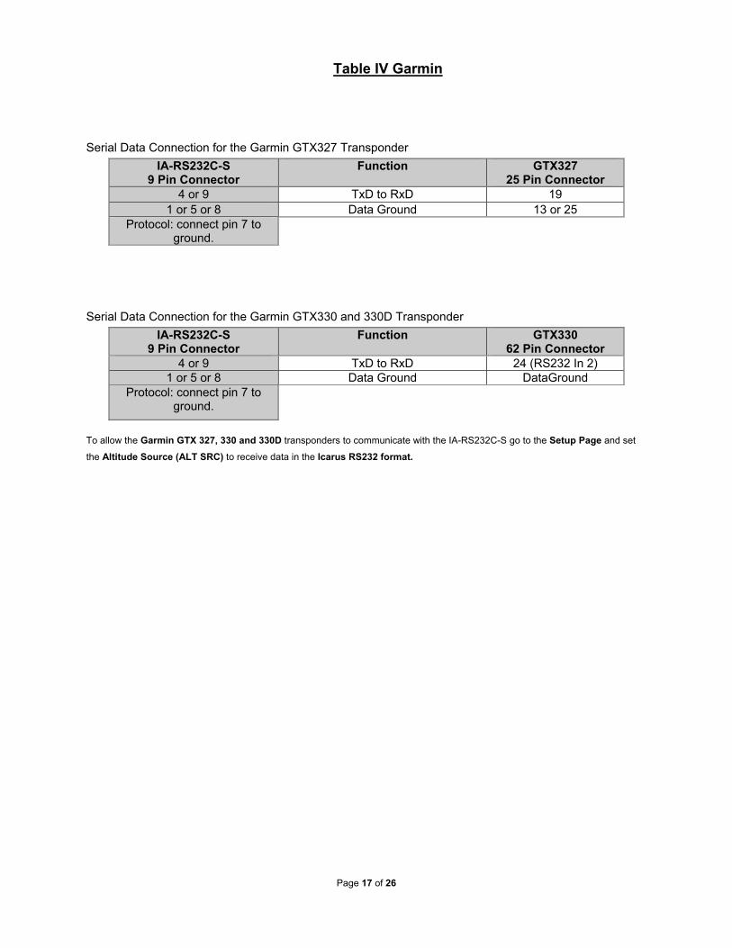
Serial Data Connection for the Garmin GTX327 Transponder IA-RS232C-S
9 Pin Connector Function GTX327
25 Pin Connector 4 or 9 TxD to RxD 19
1 or 5 or 8 Data Ground 13 or 25 Protocol: connect pin 7 to
ground.
Serial Data Connection for the Garmin GTX330 and 330D Transponder IA-RS232C-S
9 Pin Connector Function GTX330
62 Pin Connector 4 or 9 TxD to RxD 24 (RS232 In 2)
1 or 5 or 8 Data Ground DataGround Protocol: connect pin 7 to
ground.
To allow the Garmin GTX 327, 330 and 330D transponders to communicate with the IA-RS232C-S go to the Setup Page and set the Altitude Source (ALT SRC) to receive data in the Icarus RS232 format.

Page 18 of 26
Table V Edo-Air, Genave, Collins, Radair
IA-
RS232C
-S D
A-15P
Function
Edo-Air RT-777
Pin Number
Genave Beta 5000
Pin Number
Collins TDR 950
Pin Number
Radair 250
Pin Number
1 D4 15 0 3 15
2 A1 7 4 12 7
3 A2 5 5 10 6
4 A4 3 6 7 13
5 B1 12 7 6 9
9 B2 13 8 5 10
10 B4 14 9 4 11
11 C1 8 10 8 14
13 C2 6 11 11 16
12 C4 4 12 9 12
6 Output Enable 2 3
Connect to aircraft ground. 19
8 or 14 *7
14 to 28Vdc Input
Connect to aircraft’s avionics buss protected by
a fuse or circuit breaker. 2
Connect to aircraft’s avionics
buss protected by a fuse or
circuit breaker. 22
15 Ground 2 Connect to aircraft
ground. Connect to
aircraft ground. Connect to
aircraft ground.
7 Pins 8 and 14 are connected together internally.

Page 19 of 26
Table VI Bendix, Wilcox, UPS AT
IA-
RS232C
-S D
A-15P
Function
Bendix TPR-2060
Pin Number
Bendix TR641A/B
Pin Number
Wilcox 1014A
Pin Number
UPS AT Apollo SL70 Pin Number
1 D4 *8 N C 35
2 A1 4 A k 13
3 A2 6 B c 31
4 A4 8 C W 12
5 B1 9 D T 33
9 B2 10 E L 14
10 B4 11 F D 32
11 C1 3 H P 16
13 C2 5 J f 34
12 C4 7 K Z 15
6 Output Enable
Connect to aircraft ground.
Connect to aircraft ground.
Connect to aircraft ground.
Connect to aircraft ground.
8 or 14 *9
14 to 28Vdc Input
Connect to aircraft’s avionics buss
protected by a fuse or circuit breaker.
Connect to aircraft’s avionics buss
protected by a fuse or circuit breaker.
Connect to aircraft’s avionics buss protected
by a fuse or circuit breaker.
Connect to aircraft’s avionics buss protected
by a fuse or circuit breaker.
15 Ground Connect to aircraft
ground. Connect to aircraft
ground. Connect to aircraft
ground. Connect to aircraft
ground.
Serial Altitude Data Connection for the Apollo SL70 Transponder
IA-RS232C-S 9 Pin Conn. Function
UPS AT SL70
4 or 9 TxD to RxD 4
1 or 5 or 8 Ground 3
To allow the UPS AT SL70 transponder to accept serial data from the IA-RS232C-S go to the Test Mode on the SL70 Conf page and set the Altitude Source (ASrc) to receive Serial (Ser) data. On the BAUD page select 1200.
8 Data for this connection is not available at this time. 9 Pins 8 and 14 are connected internally.

Page 20 of 26
Serial Data Connector and Protocol Tables
Table VI Serial Port Connector, 9 Pin D-Subminiature DE-9S
Pin Function
1 Ground 10
2 Spare
3 Spare
4 TxD1
5 Ground 10
6 Protocol
7 Protocol
8 Ground 10
9 TxD2
Table VII
Protocol Selection: DE-9S D-Subminiature Connector Function Table
Protocol Selection Pin 6
Pin 7
UPS AT 100' resolution, 1200bps. Open Open Trimble/Garmin, 100' resolution,
9600bps. Open Gnd.
10 Pins 1 and 5 and 8 are internal grounds provided for protocol selection and serial data ground.

Page 21 of 26
GPS Connection Data
Given the speed with which new GPS units are entering the market, it is impossible to provide data on every device. The following digitizer/GPS interconnections are provided as a quick reference only, and though they are correct to the best of our knowledge, always consult the latest installation, operation, and service bulletins from the GPS manufacturer.
UPS Aviation Technologies (IIMorrow)
Apollo Model GX50, GX60, GX65
Apollo GX50, GX60, GX65
Signal
Apollo 37 Pin D-Sub
Connector
IA-RS232C-S Serial Port
Connector DE-9S
RxD2 21 4 or 9
Ground 20 1 or 5 or 8
Apollo GX50, GX60, GX65 Software Configuration
In test mode, rotate the Large knob to select serial port configuration RX. Press SEL, rotate the large knob to select the RxD2 port, rotate the small knob to select AltEnc input.
Apollo Model MX20 Multi Function Display
Apollo MX20 Signal
Apollo 37 Pin D-Sub
Connector
IA-RS232C-S Serial Port
Connector DE-9S
RxD2 21 4 or 9
Ground 3 1 or 5 or 8
Apollo MX20 Software Configuration
Under External Data Source set altitude source to Port 2.

Page 22 of 26
Trimble
Trimble 2101 Approach Plus GPS Receiver
Trimble Signal
Trimble 2101 Port 1
Trimble 2101 Port 2
IA-RS232C-S Serial Port Connector DE-9S
RxD+ 7 24 1 or 5 or 8
RxD- 8 36 4 or 9
Ground 3 or 20 3 or 20 1 or 5 or 8
Protocol assignment, jumper
pin 7 to ground on pins 1 or 5 or 8
Trimble 2101 Approach Plus GPS Receiver Software Configuration - Installation
Setup
Access the 2101 installation setup submenu and go to the SERIAL I/O SETUP. Select the GPS serial port which is to receive the pressure altitude data,
SERIAL-1 IN or SERIAL-2 IN. Set data format to ENCODER.
2101 I/O Approach Plus GPS Receiver
Trimble Signal
Trimble 2101 I/O
Serial Port 1
Trimble 2101 I/O
Serial Port 2 IA-RS232C-S
Serial Port Connector DE-9S
RxD+ J1-7 J1-24 1 or 5 or 8
RxD- J1-8 J1-36 4 or 9
Ground J1 - 3 or 20 J1 - 3 or 20 1 or 5 or 8
Protocol assignment, jumper
pin 7 to ground on pins 1 or 5 or 8
2101 I/O Approach Plus GPS Receiver Software Configuration - Installation Setup
Access the 2101 installation setup submenu and go to the SERIAL I/O SETUP. Select the GPS serial port which is to receive the pressure altitude data,
SERIAL-1 IN or SERIAL-2 IN. Set data format to ENCODER.

Page 23 of 26
Garmin International
Garmin 400 Series GPS Devices
Garmin 78 Pin Conn.
(P4001) Function
IA-RS232C-S Serial Port Connector
DE-9S
57 TxD 4 or 9
77 or 78 Ground 1 or 5 or 8
Protocol, jumper pin 7 to
ground.
Garmin 400 series GPS software configuration
To allow the Garmin 400 series GPS to communicate with the IA-RS232C-S go to the Main RS232 Config page and set channel 1 input to Icarus-alt.

Page 24 of 26
Outline Drawing

Page 25 of 26
SSD120-XX X X-XXXX
Trans-Cal Industries, Inc. Solid State Altitude DigitizerPart Number Ordering Information
Max. Operating Altitude (Feet)
30,000 -30 35,000 -35 42,000 -42 50,000 -50 62,000 -62 65,000 -65 80,000 -80 85,000 -85100,000 -100
Model Identifier Nomenclature
Encoder / Digitizer AModular Encoder MServo Module SM
Operating Temperature Range
Blank -20 to +70 C E -55 to +70 C
Additional Ports and Features
-RS232 Dual RS232 Ports-RS RS485 and Dual RS232 Ports-RS1 RS485 and 1' Resolution on TxD2
Part Number Example: SSD120-42AE-RS232Note: On models operating at 50,000 to100,000 feet, dual RS232 ports are includedas a standard feature.

Page 26 of 26
WARRANTY REGISTRATION
Trans-Cal Industries warrants each Model IA-RS232C-S Solid State digitizer / serializer to be free of defects in workmanship and materials for a period of 42 months after purchase. This warranty applies to the original purchaser of the instrument. Trans-Cal’s obligation under this warranty is limited to repairing or replacing any unit returned to Trans-Cal during the life of this warranty provided:
(1) The defective unit is returned to us, transportation pre-paid. (2) Prior approval is obtained from Trans-Cal. (3) The unit has not been damaged by misuse, neglect, improper operation, accident
alteration or improper installation. Trans-Cal DOES NOT reimburse labor costs on warranty repairs. Trans-Cal
Industries will be the sole judge as to the cause of the malfunction and wherein the responsibility lies. No other obligation or liability is expressed or implied. For the above warranty to become effective, the attached registration card must be completed and returned to Trans-Cal Industries, properly filled out and signed by the dealer selling or installing this equipment. Mail to: Trans-Cal Ind., Inc., 16141 Cohasset St., Van Nuys, CA 91406 - - - - - - - - - - - - - - - - - - - - - - - - - - - - - - - - - - - - cut here - - - - - - - - - - - - - - - - - - - - - - - - - - - - - - - - - - MODEL: IA-RS232C-S SERIAL NO: IA-___________________ AIRCRAFT:______________________ NUMBER:__________________________ OWNER:___________________________________________________________ ADDRESS:_________________________________________________________ CITY:_________________________________ STATE:_______ZIP:___________ DEALER:__________________________________________________________ INSTALLED BY:____________________________________________________ LICENSE NO:______________________________________________________ INSTALLATION DATE:_______________________________________________ I hereby certify the above instrument was installed in accordance with the instructions of Trans-Cal Industries, and the installation was done to industry standards. I further certify the instrument was properly working on the above date. SIGNED:___________________________________________________________ PRINT NAME:_____________________________________________________________

![Dlink+ w/CPDLC Technical Description 14114 1 [XX] w/CPDLC Technical Description Document Number: TD ... Environmental DO‐160E ...](https://static.fdocuments.in/doc/165x107/5aded5907f8b9afd1a8be4a7/dlink-wcpdlc-technical-description-14114-1-xx-wcpdlc-technical-description.jpg)


![V K1 · 2016. 3. 30. · q]^O 6-75 A B A B]^O 6---7 fghO 6---75 A B 2 ˘ 2 2 2 ... defeX ghU [iP. jklmnop ˙ ˙ ...](https://static.fdocuments.in/doc/165x107/5fe40ef6b64b801da22bf28f/v-k1-2016-3-30-qo-6-75-a-b-a-bo-6-7-fgho-6-75-a-b-2-2-2-2-defex.jpg)


![jklmnop q r s...‚ fiflŁŒflflŠŸŽıł œ mn šž €¡ ¡ ¡ «‹ ›fi € æ ¡fl –† ‡I·˛ÙNOPh Lƒ]figVIµ \” ł−VÑ Is T‹W v TGHłœLNŽJILI•m m ...](https://static.fdocuments.in/doc/165x107/5e4de30fb124f362a966fbf2/jklmnop-q-r-s-a-iiii-mn-a-a-ai.jpg)