TRAINING GUIDE FOR LOCAL BLACKSMITHS FROM...
88
1 TRAINING GUIDE FOR LOCAL BLACKSMITHS FROM THE THREE NORTHERN REGIONS OF GHANA TOPIC: THRESHERS 101 VENUE: TAMALE IMPLEMENT FACTORY PREPARED BY ABDULAI GABRIEL AYICHIM ZULKARINI ISSAHAKU BABA JULY- 2016
-
Upload
phungkhanh -
Category
Documents
-
view
214 -
download
0
Transcript of TRAINING GUIDE FOR LOCAL BLACKSMITHS FROM...

1
TRAINING GUIDE FOR LOCAL BLACKSMITHS FROM THE THREE
NORTHERN REGIONS OF GHANA
TOPIC: THRESHERS 101
VENUE: TAMALE IMPLEMENT FACTORY
PREPARED BY
ABDULAI GABRIEL AYICHIM ZULKARINI
ISSAHAKU BABA
JULY- 2016

2
TOPICS UNDER CONSIDERATION
Threshers
What is a Thresher
Basic Parts and Functions of a Thresher
Types of Threshers
Threshing Drums
Thresher Motors
Materials Selection for Thresher Construction
Interpretation of AUTOCAD drawings
Welding and Fabrication techniques
Welding Operations
Types of Welding Operations
Safety Precautions

3
THRESHERS 101

4
CHAPTER ONE
1.0 WHAT IS A THRESHER?
A thresher is a machine which separates the seeds from the stalk (pinnacle in the case of rice)
and winnows it by means of blower to obtain clean seeds or grains. Threshing involves three
distinct operations: separating the grain from the ear or panicle (the most energy intensive
operation); sorting the grain from the straw; and winnowing the chaff from the grain. The
threshing can be achieved by three methods: Rubbing action, Impact and Stripping.
Fig. 1: Diagram of a thresher (Source: Indian Standard Institution, 1986).

5
1.1 Basic Parts and Functions of a thresher
1.1.2 Threshing Drum
The threshing drum is the most relevant part of the thresher. This component beats the crop to
release seeds or grains. This action is accomplished by beating the crop against the concave. The
speed of the thresher is determined by the pulley of the thresher with respect to the diameter of
the drive motor/engine.
Fig. 2: Spike tooth Threshing drum
1.1.3 Blower/Fan
The blower or fan (commonly called) plays an important role in cleaning threshed grain. The fan
does this by generating a film of air and blowing it across the direction of threshed grains to get
rid of debris and other unwanted particles. The blower is also driven by the motor with its speed
controlled by the motor’s pulley. Air can only remove impurities which have different
aerodynamic properties from the gran. A thresher that is provided with aspirator unit is usually
called aspirator type thresher. Those threshers fitted with blower which blows air in horizontal
direction is called drummy threshers.

6
1.1.4 Fan adjustment
Fan(s) fitted on thresher must provide the proper amount of blast. The shutter(s) at each end of
fan should be adjusted properly so that it could provide blast sufficient enough to remove chaff
and light materials without grain. Watching the sample and adjusting the blast can help in getting
the desired results.
Fig. 3: Fan or blower of thresher (aspirator type- Sudajana et. al, 2002)
1.1.4 Concave/Sieve
Cylinder and concave together makes the threshing unit. It separates the grain from the crop and
removes grain from the straw. Concave is provided in the thresher to hold the fed crop inside the
threshing chamber and allows only grain and small amount of chaff to pass through it. The
threshing takes place only in this space. It is a curved unit, made of iron steel or iron bar, fitted
near the threshing cylinder. The clearance between cylinder and concave is adjustable, depending
upon the size and type of grain. As the concave clearance is reduced, the threshing efficiency
increases but losses increase and vice versa. The concave clearance at the inlet is less as
compared to outlet. There are different types of concave, which are used in thresher.
7
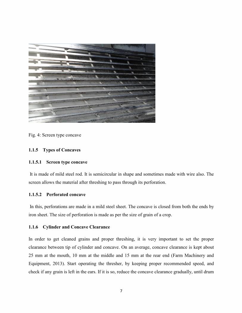
Fig. 4: Screen type concave
1.1.5 Types of Concaves
1.1.5.1 Screen type concave
It is made of mild steel rod. It is semicircular in shape and sometimes made with wire also. The
screen allows the material after threshing to pass through its perforation.
1.1.5.2 Perforated concave
In this, perforations are made in a mild steel sheet. The concave is closed from both the ends by
iron sheet. The size of perforation is made as per the size of grain of a crop.
1.1.6 Cylinder and Concave Clearance
In order to get cleaned grains and proper threshing, it is very important to set the proper
clearance between tip of cylinder and concave. On an average, concave clearance is kept about
25 mm at the mouth, 10 mm at the middle and 15 mm at the rear end (Farm Machinery and
Equipment, 2013). Start operating the thresher, by keeping proper recommended speed, and
check if any grain is left in the ears. If it is so, reduce the concave clearance gradually, until drum

8
is threshing cleanly. Too close concave clearance setting is likely to crack some of the grains and
too open concave clearance will result in improper threshing of crops.
Fig. 5: Cylinder concave clearance between loop cylinder and screen concave type
1.1.7 Shaker
The screens are oscillated or shaken with a crank attached to the screen. This crank is powered
from main axle either by belt or by rod. The circular motion of the main shaft is converted into
oscillating motion of screen, which shakes it and separates the grain from other foreign material
and chaff. The separating effectiveness depends on the frequency of strokes of crank, which is
adjustable. The shaker, which is not always found on all threshers, plays a very important role in
sorting threshed grains.
1.1.8 Chute
The chute of a thresher is an outlet for the emission of threshed crops or an outlet for the
collection of seed.

9
1.1.9 Transport Wheels
Threshers are provided with wheels to make movement on the field easier. These wheels are
made mostly with cost iron but new and large capacity threshers are equipped with pneumatic
wheels for better performance during transportation. Transport wheels should not be so small as
movement on the field will be impeded.

10
CHAPTER TWO
2.0 Types of Threshers
Threshers can be classified based on the power usage as seed below.
2.1 Power Source
The type of power used to drive the motor defines the type of thresher in use. The source of
power also determines the quality of work output. The power also determines the amount of time
spent in threshing crops. Below are different classifications of threshers based on their power
sources.
2.1.1 Manual
Manual threshers are human powered. These threshers require human power to drive their
threshing drums and blowers. The action of a pedal actuates the threshing drum for threshing.
The problem with the manual threshers is inconsistent threshing drum and blower speeds.
2.1.2 Electric
Electricity driven threshers are another group of common threshers. These threshers have motors
which are driven by electricity. The problem with this thresher is that it cannot be moved further
away from electricity sources.
2.1.3 Motor
Motors are the most common of all the power sources for power generation on threshers. These
motors are either powered by gas (petrol) or diesel. The horse power of the motor usually
determines the work output of the thresher.
2.1.4 PTO (Power Take Off) shaft
These groups of threshers are usually very large and towed by the tractor. These threshers are
driven by the tractor PTO shaft at very high speeds. Care needs to be taking in operating these
threshers because of the PTO shaft. Negligence in its usage can result in serious harm to hand
and body.

11
CHAPTER THREE
3.0 Types of Threshing Drums
The operation of detaching the grains from the ear head, cob or pod is called threshing. It is
basically the removal of grains from the plant by striking, treading or rupturing. The diameter of
threshing drums should not be too small as it will end up wrapping crop material around its
periphery resulting in crops getting trapped in the cylinder.
3.1 Spike Tooth Type Cylinder
In this type of threshing drum, there is a hollow cylinder, made out of Mild Steel flat bars. Over
to its entire periphery, a number of spikes/pegs of square /round bars or flat iron pieces are
welded or bolted. Now days, in most of threshers, round peg with adjustable length are used.
These spikes are staggered on the periphery of the drum for uniform threshing. The crop is fed
along with the direction of motion of the rotating drum. The spike tooth cylinders are available in
various sizes. A spike tooth cylinder with spikes of flat front and streamlined back has lower
energy consumption. The spike tooth cylinder have been very efficient in threshing soya beans,
rice and sun flower.
3.1.2 Rasp Bar Type Cylinder
In this type of cylinder, there are slotted plates, which are fitted over to the cylinder rings, in
such a way that the direction of slot of one plate is opposite to another plate. This type of
cylinder is commonly used in threshers. It can be used for a wide variety of crops viz.-wheat,
paddy, maize, soybean etc.
3.1.3 Wire Loop Type Cylinder
In this type of threshing drum, there is hollow cylinder, over which a number of wooden or Mild
Steel plates are fitted. On these plates, number of wire loops is fixed for threshing purposes. This
type of cylinder is common in the manually operated paddy threshers. Holding the bundle
against the loops of revolving cylinder does threshing of paddy crop. This type of threshing drum
is excellent for paddy threshing.

12
Fig. 8: Types of threshing drums (Source: Farm Machinery and Equipment, 2013).

13
Fig. 9: Different types of threshing drums (Spike tooth and rasp bar type- Sudajana et. al, 2002)
Fig. 10: Wire loop threshing drum

14
CHAPTER FOUR
4.0 Motors
Motors are the main source of power for most mechanical threshers. These motors which come
in different capacities either run on diesel or gas (petrol). These motors are equipped with pulleys
which run on belts to drive the components of the thresher.
4.1 Diesel Motors
Diesel motors come in different size and capacities. Diesel motors are powered by diesel to run
their four stroke engines. Starting the motors requires the cranking of the engine with a crank
handle whilst holding the displacement handle. To start this machine, a little effort is required
from the operator or user.
Fig. 8: Diesel powered motor

15
4.2 Gas (Petrol) Motors
These motors unlike the diesel motors are powered by gasoline fuel to function. Gas motors used
on thresher are mostly four stroke and range in capacity based on the size of the thresher under
consideration. Larger capacity means higher cost and maintenance. The market today has so
many sales points for thresher motors but care should be taken in selecting a motor for your
thresher since many fake machines are available on the market.
The type of motor used on a thresher is determined by the cost of the motor, availability on the
local market and ease of maintenance and usage by the customer. The capacity of the motor will
also be determined by the size and weight of materials used in the construction of some critical
components such as the threshing drum and the blower.
Fig. 9: Gas (Petrol) powered motor

16
CHAPTER FIVE
5.0 Materials Selection for Threshers
The design and fabrication of threshers cannot be complete with the use of the requisite
materials. Metals are the predominant materials used in the construction and fabrication of
threshers. The most common metal used in the construction of threshers is mild steel.
5.1 Mild Steel
Mild steel contains approximately 0.005-0.25% carbon making it malleable and ductile. Mild
steel has a relatively low tensile strength, but it is cheap and easy to form; it is often used when
large quantities of steel are needed. Mild steel contain less steel carbon than other steels and are
easier to cold-form, making them easier to handle. Below are some properties of mild steel
which makes them excellent choices for thresher fabrication.
5.2 Properties of Mild steel
5.2.1 Weldability
Weldability is defined as “the capacity of a material to be welded under the imposed fabrication
conditions into a specific, suitably designed structure and to perform satisfactorily in the
intended service”. Carbon steel is generally considered to be quite weldable, particularly when
the carbon content is below 0.35%. The term weldability is also used in a narrower sense to
mean the ease with which a material can be welded without cracking or other discontinuities.
Mild steels and rarely present problems, as long as impurity levels are kept low. Mild steel are all
weldable without preheat, using any of the common welding processes.

17
5.2.3 Forming or Forging
Forming operations on carbon steels include any method of plastically deforming the material to
achieve the desired component. Included are bending (both hot and cold), rolling, extrusion,
drawing, and forging. Carbon steels are capable of being formed extensively due to the relatively
high ductility of the material. Forming that is performed at temperatures lower than the
transformation temperatures will result in cold strain, which can both increase the strength and
reduce the ductility of the component. Mild steel can be formed into different shapes and forms.
5.2.4 Machinability
Machinability can simply be defined as the ease with which a material can be machined.
Machinability can be based on tool life, cutting speed, power consumption, comparison with
standard steels, quality of surface finish, and feeds resulting from constant thrust force. As with
other properties such as strength, hardness, and ductility carbon content is the dominant factor in
machinability. Mild steels can easily be machined with the right tools whether the shaft or metal
sheet.
5.3 Cast Iron
Cast iron is a group of iron-carbon alloys with carbon content greater than 2%. The alloy
constituents affect its colour when fractured. Cast iron is a metal which is recommended for
very few component of the thresher as seen in Table1 below.
5.3.1 Types of Cast Iron
Gray cast iron
White cast iron
Nodular cast irons
Malleable cast irons
5.3.2 Disadvantages of Cast Iron
Cast iron has low strength
Cast iron has no plastic strain (brittle)

18
5.3.3 Advantages of Cast Iron
Good compressive strength
High damping capability (tool machines)
Good machinability
Good wear resistance (graphite as lubricant)
Lower cost
Table 1: Materials selected for different parts of the Thresher
No. Name of Part Material
1 Frame Mild Steel
2 Shaft Mild Steel
3 Concave Mild Steel
4 Threshing cylinder cover Mild Steel
5 Blower Mild Steel
7 Fly wheel Cast Iron
8 Pulley Cast Iron
9 Transport wheels Cast Iron/Mild Steel
10 Threshing cylinder Mild Steel/Cast Steel/Cast Iron
(Source: Indian standard institution, 1986)

19
CHAPTER SIX
6.0 AUTOCAD DRAWINGS
Computer Aided Designs are electronic representations of machine parts and buildings. These
electronic representations are displayed in different views to enhance proper interpretation of the
information. Understanding AUTOCAD drawings are essential in the construction of threshers
as all engineering drawings are often drawn using computer softwares. AUTOCAD drawings are
usually well dimensioned and presented in autographic views. Below is a simple illustration of
how AUTOCAD drawings will be represented on the sheet before fabricating the blue print.
6.1 Basic Autographic view interpretation
10cm
15cm
7cm
Plan

20
Fig. 11: Front view of box
Fig.11: Right hand view of box
10cm
12cm
10cm
12cm

21
Fig.14: Plan of box
The above figures represent the different views by which the box can be viewed. When these
views are observed, the later drawings are presented in two (2) dimensions instead of three (3).
The 2D views are also well dimensioned to illustrate the real length of the parts under study.
Dimensions are usually in metric standards.
15cm
7cm

22
CHAPTER SEVEN
7.0 Welding
Welding is a joining process in which metals or sometimes plastics are heated, melted and mixed
to produce a joint with properties similar to those of the materials being joined.
There are three main components needed to create a weld. These are:
A heat source such as an electric arc, a flame, pressure, or friction. The most common
heat source is an electric arc. An arc is the physical gap between the end of the electrode
and the base metal. The physical gap causes heat due to resistance of the current flow and
arc rays. The arc melts to create the joint.
Shielding, which is the use of gas or another substance to protect the weld from air as the
weld is being formed. Oxygen from the air makes welds brittle and porous.
Filler material, which is the material used to join to the two pieces together.
(Source: Thomson Rivers University, 2014).
7.1 Types of welding processes
7.1.1 Arch Welding
A welding power supply is used to create and main an electric arc between an electrode and the
base material to melt metals at the welding point. In such welding process, the power supply
could be AC or DC. The electrode could be consumable or non-consumable and a filler material
may or may not be added.
The most common types of arc welding are:
Shielded Arc Welding
Gas Metal Arc Welding
Gas Tungsten Arch Welding

23
7.1.1.1 Shielded Metal Arc Welding (SMAW)
A process that uses a coated consumable electrode to lay the weld. As the electrode melts, the
flux coating disintegrates, giving off shielding gases that protect the weld area from atmospheric
gases and provides molten slag which covers the filler metal as it travels from the electrode to
the weld pool. Once the part of the weld pool, the slag floats to the surface and protects the weld
from contamination as it solidifies. Once hardened, the slag must be chipped away to reveal the
finish.
Fig. 15: Shielded arc welding operation
7.2 Gas Welding
In this method a focused a focused high temperature flame generated by gas combustion is used
to melt the work pieces (and filler) together. The most common type of gas welding is oxy-fuel
welding where acetylene is combusted in oxygen.

24
7.3 Resistance Welding
Resistance welding involves the generation of heat by passing a high current (1000-100,000 A)
through the resistance caused by the contact between two or more metals surfaces which causes
pools of molten metal to be formed at the weld area. The most common types of resistance
welding are spot welding (using pointed electrodes) and Seam-welding (using wheel shaped
electrodes).
7.4 Energy Beam Welding
In this method a focused high energy beam (Laser beam or electron beam) is used to melt the
work pieces and thus join them together.
7.5 Solid-State Welding
In contrast to other welding methods, solid-state welding processes do not involve the melting of
the materials being joined. Common types of solid-state welding include; Ultrasonic welding,
explosion welding, electromagnetic pulse welding, roll welding, friction welding (including
friction-stir-welding), etc.
7.6 Welding Terminologies
There is some special technical vocabulary that is used in welding. The basic terms of the
welding language include:
7.6.1 Filler Material
When welding two pieces of metal together, we often have to leave a space between the join.
The material that is added to fill this space during the welding process is known as filler material
(filler metal).

25
7.6.2 Welding Rod
The term welding rod refers to a form of filler metal that does not conduct an electric current
during the welding process. The only purpose of a welding rod is to supply filler meal to the
joint. This type of filler metal is often used for gas welding.
7.6.3 Electrode
In electric-arc welding, the term electrode refers to the component that conducts the current
from the electrode holder to the metal being welded. Electrodes are classified into two groups:
consumable and non-consumable.
Structure of covered electrode (Source: KOBE STEEL LTD., 2015).
7.6.4 Consumable electrode
They do not only provide a path for the current but they also supply filler metal to the join. An
example is the electrode used in shielded metal-arc welding.
7.6.5 Non-consumable electrode
These are only sued as conductor for the electrical current, such as in gas tungsten arc welding.
The filler for gas tungsten arc welding is a hand fed consumable rod.

26
7.6.6 Flux
Before performing any welding process, the base metal must be cleaned from impurities such as
oxides (rust). Unless these oxides are removed by using a proper flux, a faulty weld may result.
The term flux refers to material used to dissolve oxides and release trapped gases and slag
(impurities) from the base metal such that the filler metal and the base metal can be fused
together. Fluxes come in the form of paste, powder, or liquid. Different types of fluxes are
available and the selection of appropriate flux is usually based on the type of welding and type of
base metal
7.8 Safety in Welding
Safety precautions are required in ensuring the health of the professional and the safety of the
working environment. Below are some welding precautions for ensuring safety at the welding
shop.

27
7.9 Personal Safety
(Source: Thomson Rivers University, 2014).

28
7.9.2 Safety Tips for Using Protective Clothing
Wear clothing made from heavyweight, tightly woven, 100% wool or cotton to protect from UV
radiation, hot metal, sparks and open flames. Flame retardant treatments become less effective
with repeated laundering.
1. Keep clothing clean and free of oils, greases and combustible contaminants.
2. Wear long-sleeved shirts with buttoned cuffs and a collar to protect the neck. Dark
colours prevent light reflection.
3. Tape shirt pockets closed to avoid collecting sparks or hot metal or keep them covered
with flaps.
4. Pant legs must not have cuffs and must cover the tops of the boots. Cuffs can collect
sparks.
5. Repair all frayed edges, tears or holes in clothing.
6. Wear high top boots fully laced to prevent sparks from entering into the boots.
7. Use fire-resistant boot protectors or spats strapped around the pant legs and boot tops, to
prevent sparks from bouncing in the top of the boots.
8. Remove all ignition sources such as matches and butane lighters from pockets. Hot
welding sparks may light the matches or ignite leaking lighter fuel.
9. Wear gauntlet-type cuff leather gloves or protective sleeves of similar material, to protect
wrists and forearms. Leather is a good electrical insulator if kept dry.
10. Direct any spark spray away from your clothing.
11. Wear leather aprons to protect your chest and lap from sparks when standing or sitting.
12. Wear layers of clothing. To prevent sweating, avoid overdressing in cold weather.
Sweaty clothes cause rapid heat loss. Leather welding jackets are not very breathable and
can make you sweat if you are overdressed.
13. Wear a fire-resistant skull cap or balaclava hood under your helmet to protect your head
from burns and UV radiation.
14. Wear a welder's face shield to protect your face from UV radiation and flying particles.

29
7.9.3 Work Place Safety
Tidy up the work place and remove any flammable materials, liquids and gases from workplace
and adjacent spaces including spaces above/below decks, behind bulkheads and inside pipes or
containers. Cover any openings through which sparks may be led to other areas onboard which
have not been prepared for hot work.
Shield the work place to protect others from sparks and radiation from the arc, and post a
warning sign that welding is in progress.
Ensure that sufficient and correct fire fighting equipment is available at the workplace,
and that personnel familiar with its use is present. Ensure that the work place is properly
ventilated, if necessary with special fume extraction equipment. This is especially
important when working on galvanized or coated surfaces which may produce harmful
fumes when heated.
Provide enough ventilation wherever welding and cutting are performed. Proper
ventilation will protect the operator from the evolving noxious fumes and gases. The
degree and type of ventilation will depend on the specific welding and cutting operation.
It varies with the size of work area; on the number of operators; and on the types of
materials to be welded or cut. Potentially hazardous materials may exist in certain fluxes,
coatings, and filler metals. They can be released into (lie atmosphere during welding and
cutting.
Check the welding atmosphere and ventilation system if workers develop unusual
symptoms or complaints. Do not weld on dirty plate or plate contaminated with unknown
material. The fumes and gases which are formed could be hazardous to your health.
Remove all paint and galvanized coatings before welding. All fumes and gases should be
considered as potentially hazardous.
Do not weld near vapor degreasers or on metal that has been just degreased. The
decomposition of chlorinated hydrocarbons used in vapor degreasers can form into a
poisonous gas.

30
CHAPTER EIGHT
8.0 REFERENCE
1. Farm Machinery and Equipment (2013). Lesson 9. Principles and types of Threshers;
constructional details, features and adjustments.
2. Indian Standard Institution (1986). Indian standard – Specification for power thresher,
spike tooth type. IS: 11691 - 1986.
3. KOBE STEEL LTD. (2015). The ABD’s of welding and inspection. 5-9-12 Kita-
shinagawa-Ku, Tokyo 141-8688 Japan.
4. Sudajana S., Salokhe V.M., Triratanasirichaib K. (2002). Effect of Type of Drum, Drum
Speed and Feed Rate on Sunflower Threshing. Biosystems Engineering (2002) 83(4),
413–421.
5. The Hashemite University. Introduction to welding technology-introduction to non-
destructive techniques.
6. Thomson Rivers University (2014). Welding Safety Procedures. Number: OH&S 18.35.


430mm

430mm
430mm

430mm


1
SIL POWER THRESHER [3000] OPERATIONAL MANUAL
Developed by: Abdulai Gabriel Ayichim Zulkarini August-2016

2
INTRODUCTION The essence of this manual is to provide relevant information for the operation of the SIL power thresher. The thresher is an important machine if well taken care of will help alleviate the challenges associated with threshing soybeans.
We therefore wish to edge you to follow carefully the instruction in this manual as it will enable you properly handle and take care of your thresher.
In the case of any challenges which will require you to seek external help, call the numbers on your thresher and this will be resolved.
Thank you for spending time to read and adhere to the instructions in this manual.

3
PART NAME
Hopper
Threshing drum cover
Blower
Handle
Transport wheels
Blower chute
Drum cover chute
Stand
Blower shatter Shatter handle
Seed collection outlet
Engine mounting

4
THRESHER OPERATION MECHANISM
A: Feeding point for Soybeans
B: Exit for stems of Soybeans
C: Exit for chaff and small debris
D: Exit for clean Soybeans

5
THRESHER OPERATION MECHANISM The diagram above is an illustration of the operation of the thresher. Below is an explanation of the working operation of the thresher.
Feeding System[A]
The feeding system consists of a hopper designed with a sloped neck to prevent the user from getting his or her hand entangled in the spikes of the threshing drum. The neck is also sloped at an angle to prevent the shooting of seeds during threshing operations.
Chute/Exit system
After soybeans is feed into the thresher, there exist different chute or exit systems for the thresher.
Stems chute [B]
This chute is the pathway for the threshed stems to find their way out of the thresher.
Debris chute [C]
This chute allows smaller debris produced from threshing to be carried away by the film of air generated by the blower.
Seed chute [D]
This outlet allows seeds to flow into a receptacle after threshing.

6
THRESHER MAINTENANCE AND PRECAUSTIONS 1. Ensure that the thresher is properly stored after use; store thresher in a shed or under a
tarpaulin to avoid direct contact with sunlight/rain. 2. Grease your pillow bearings regularly (at least twice a week during threshing season)
3. Ensure that the engine of your thresher is regularly serviced.
4. Do not overload your thresher during operations as this can shorten the life span of your engine.
5. Tighten all bolts and nuts regularly to avoid vibration.
6. Follow all instruction in this manual carefully.
7. Ensure that all belts are well tensioned during threshing operations.
Grease bearings through their nipples using a grease gun regularly

7
8. Avoid the belt area during operations to prevent damage to operators.
9. Put off your engine in the event that your thresher gets stuck before trying to remove the blocked material.
10. Avoid putting your hand into the threshing drum hopper during operations as this can result in damage to fingers.

8
TROUBLE SHOOTING
No. Problem Causes/solved 1 Thresher stopped during operation Thresher overload, exhausted fuel, torn belt 2 Poor cleaning efficiency Loose blower belt, unopened blower
shatters 3 Seed in stalk Low engine speed, check belt tension 4 High vibration Loose bolts and nuts 5 Crashed seeds High engine speed 6 Poor engine start poor fuel, air cleaner blocked, inspect
carburetor for over float

9

ThisdocumentismadepossiblebythegeneroussupportoftheAmericanpeoplethroughtheUnitedStatesAgencyforInternationalDevelopment. ThecontentsaretheresponsibilityoftheSoybeanInnovationLabanddonotnecessarilyreflecttheviewsofUSAIDortheUnitedStatesGovernment.