
th July 2015 MST-REP-002-01 Thresher Prototype No.1 Design...
20
Consultancy report for MOST 27 th July 2015 MST-REP-002-01 Thresher Prototype No.1 Design Dossier For any questions / queries: Thrive PO Box 2783 Blantyre Malawi [email protected] 0991 122 769 or [email protected] 0991 122 768 Thrive is a business registered in Malawi, company number 178144 Commercial In Confidence
-
Upload
truongtuyen -
Category
Documents
-
view
216 -
download
3
Transcript of th July 2015 MST-REP-002-01 Thresher Prototype No.1 Design...

Consultancy report for MOST 27th July 2015
MST-REP-002-01 Thresher Prototype No.1 Design Dossier
For any questions / queries:
Thrive
PO Box 2783
Blantyre
Malawi
0991 122 769
or
0991 122 768
Thrive is a business registered in Malawi, company number 178144
Commercial In Confidence

Commercial In Confidence
2
Table of Contents 1. Introduction ............................................................................................................................. 4
1.1. CAD Note .......................................................................................................................................... 5 1.2. Materials and Operations .......................................................................................................... 5
2. General Assembly .................................................................................................................. 7
3. Design Process ........................................................................................................................ 8
3.1. Threshing mechanism ................................................................................................................. 8 3.2. Bearings ......................................................................................................................................... 13 3.3. Bearing Support Frame ............................................................................................................ 13 3.4. Stator Blade Position ................................................................................................................. 14
3.5. Filter ...................................................................................................................................... 16
3.6. Lid .......................................................................................................................................... 17
3.7. Frame .............................................................................................................................................. 18
4. Power Input ........................................................................................................................... 19
4.1. Diesel/Petrol ................................................................................................................................ 19 4.2. Human Powered .......................................................................................................................... 19
5. Construction Points ............................................................................................................. 19
6. Assembly Points ................................................................................................................... 20
7. Prototype Manufacture ...................................................................................................... 20
8. Other Documentation ......................................................................................................... 20

Commercial In Confidence
3
Table of Figures Figure 1 - Domasso electric thresher (left) and diesel thresher (right) .................................... 4 Figure 2 - Isometric general assembly view of prototype No. 1 .............................................. 5 Figure 4 - Domasso thresher rotor .......................................................................................... 8 Figure 5 - Domasso thresher stator ........................................................................................ 9 Figure 6 - Domasso thresher; rotor/stator interface ................................................................ 9 Figure 7 - CAD View of Rotor and Stator .............................................................................. 10 Figure 8 - Rotor/Stator dimensions ....................................................................................... 10 Figure 9 - Rotor assembly drawing - NOT TO SCALE ......................................................... 11 Figure 10 - Stator blade assembly drawing - NOT TO SCALE ............................................. 12 Figure 11 - Domasso bearing mounting, Electric (Left) and Diesel (Rgiht) .......................... 13 Figure 12 - CAD image of the bearing support frame ........................................................... 14 Figure 13 - Stator base bar void filled with chaff ................................................................... 15 Figure 14 - Domasso thresher showing top two stator blades .............................................. 15 Figure 15 - MOST thresher showing top two stator blades .................................................. 15 Figure 16 - Stator bar base void filled with chaff ................................................................... 16 Figure 17 - Stator bars and support ...................................................................................... 17 Figure 18 - Domasso lid ........................................................................................................ 17 Figure 19 - MOST Lid ........................................................................................................... 18 Figure 20 - MOST Frame ...................................................................................................... 18
Commercial In Confidence
4
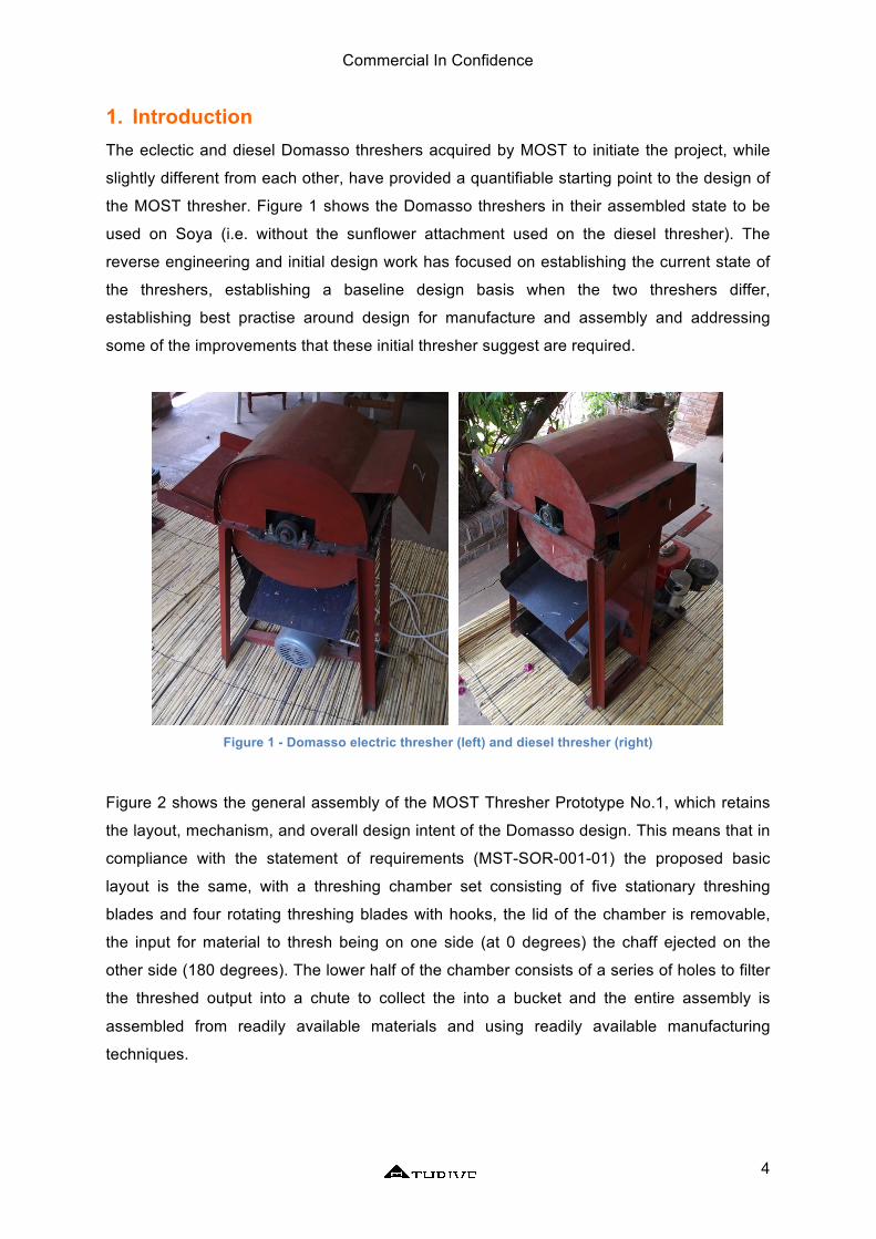
1. Introduction The eclectic and diesel Domasso threshers acquired by MOST to initiate the project, while
slightly different from each other, have provided a quantifiable starting point to the design of
the MOST thresher. Figure 1 shows the Domasso threshers in their assembled state to be
used on Soya (i.e. without the sunflower attachment used on the diesel thresher). The
reverse engineering and initial design work has focused on establishing the current state of
the threshers, establishing a baseline design basis when the two threshers differ,
establishing best practise around design for manufacture and assembly and addressing
some of the improvements that these initial thresher suggest are required.
Figure 1 - Domasso electric thresher (left) and diesel thresher (right)
Figure 2 shows the general assembly of the MOST Thresher Prototype No.1, which retains
the layout, mechanism, and overall design intent of the Domasso design. This means that in
compliance with the statement of requirements (MST-SOR-001-01) the proposed basic
layout is the same, with a threshing chamber set consisting of five stationary threshing
blades and four rotating threshing blades with hooks, the lid of the chamber is removable,
the input for material to thresh being on one side (at 0 degrees) the chaff ejected on the
other side (180 degrees). The lower half of the chamber consists of a series of holes to filter
the threshed output into a chute to collect the into a bucket and the entire assembly is
assembled from readily available materials and using readily available manufacturing
techniques.

Commercial In Confidence
5
Figure 2 - Isometric general assembly view of prototype No. 1
This design dossier will detail the reverse engineering and benchmarking process alongside
the design and manufacture process for the MOST No.1 thresher. Full manufacturing
drawings are available and some of them are included here when required. Much of the
detail of this report features photos of the original threshers along side the Computer Aided
Design (CAD) images of the MOST design to explain design decisions.
1.1. CAD Note The design work has all been produced using the Autodesk Fusion 360 CAD package. This
has been used as it is available for download (http://www.autodesk.com/products/fusion-
360/overview)and use either for free or at a low cost and will run on a variety of computers
(including PCs and Macs) meaning that once the project is complete, all of the source files
will be available for other people to use, refine, develop etc. which aligns with the intention to
make the MOST thresher an open source design which can be improved in Malawi.
1.2. Materials and Operations The design uses:
- 40mm x 40mm steel angle
- 2mm sheet steel

Commercial In Confidence
6
- 8mm thick plate / bar
- 8-10mm diameter rebar
- 20mm diameter bar
The operations required are:
- Welding
- Sheet metal bending
- Cutting plate, sheet, bar
- General assembly (nuts, bolts, aligning things etc.)
A lot of time has been put into ensuring that this design in manufacturable in Malawi using
non-specialist equipment, this also means that the finished thresher will be able to be
repaired in Malawi using the same level of equipment if the need arises.
Full part drawings are available and provided to the prototype manufacturer and following
refinement and design freeze to all interested parties and in hard and soft copy to MOST for
dissemination and future use.

Commercial In Confidence
7
2. General Assembly
Figure 3 - General assembly drawing - NOT TO SCALE

Commercial In Confidence
8
3. Design Process
3.1. Threshing mechanism The starting point for the thresher reverse engineering and the key to the whole machine is
the threshing chamber and the mechanism for carrying out the threshing activity. The
threshing chamber consists of a rotating element (the rotor) and a stationary element (the
stator) to carry out the threshing; the rotating element consists of four sets of five blades,
orientated at 90o to each other which is driven at one end from the power input (electric or
diesel) while the stationary element of the threshing mechanism consists of five sets of six
blades mounted into the threshing chamber and arranged equally around approximately
180o of the chamber base.
Figure 4 shows the rotor of the Domasso threshing mechanism removed from the machine,
Figure 5 shows the stator, along with the mesh through which the threshed material falls and
Figure 6 shows the interface between the rotor and the stator at the material input (also
showing some of the variance in the manufacture).
Figure 4 - Domasso thresher rotor

Commercial In Confidence
9
Figure 5 - Domasso thresher stator
Figure 6 - Domasso thresher; rotor/stator interface
There is some difference in terms of the dimensions, spacing and alignment of the relevant
parts of the threshing mechanism across the two machines, so the reverse engineering
process defined the relevant spacing and orientation of the blades based on the two
machines available and the conversations and inspection of the original Domasso machine
in Mponela. Figure 7 shows a CAD image of the rotating and stationary elements with the
other parts of the machine hidden to aid the view. Figure 8 shows the interaction between
the two sets of blades and the dimensions defined during the reverse engineering phase.

Commercial In Confidence
10
Figure 7 - CAD View of Rotor and Stator
Figure 8 - Rotor/Stator dimensions
The blades are manufactured from 38mm by 6mm flat steel bar with rebar used for the hook
on the rotor blades. Drawings of each component will be provided to the manufacturer and
refined during the prototype manufacture. The work in progress (WIP) assembly drawing of
the rotor is shown in Figure 9 with some relevant dimensions included and a WIP stator
blade assembly drawing is shown in Figure 10. These parts are the starting point for the
design and assembly of the entire machine, ensuring that the rotor is accurate and straight
will make the rest of the build more straightforward.

Commercial In Confidence
11
Figure 9 - Rotor assembly drawing - NOT TO SCALE

Commercial In Confidence
12
Figure 10 - Stator blade assembly drawing - NOT TO SCALE

Commercial In Confidence
13
Note: The rotor assembly alone consists of 47 parts, across six different part numbers; each
part number has its own manufacturing drawing and where appropriate sub level assembly
drawings are used to aid manufacture of the assemblies shown. These drawings are not all
included in this report, these drawings will all be provided to the prototype manufacturer and
refined during the manufacture process.
3.2. Bearings The Domasso threshers utilised basic bearing units which are designed to cope with a small
amount of axial misalignment, this standard will be utilised going forward as it avoids the
need for very tight tolerances in the manufacturing process and is also a readily available
design. Self-aligning ball bearings or toroidal roller bearings in a casing with a grease port
are suitable for this application and are readily available in manufacturing areas in Malawi.
3.3. Bearing Support Frame The frame, which supports the bearings, defines the datum for the rest of the assembly;
between the two Domasso threshers there were two styles of bearing support, shown in
Figure 11, each of which has benefits for usage in the thresher. The electric thresher
features a slightly lowered bearing mounting plate compared to the level of the join between
the threshing chamber lid and base brining the centre of the rotor axle to the centre level of
the threshing chamber; whereas the diesel thresher use a flat mount below the centreline of
the rotor axle. The style used on the diesel thresher has been chosen for the MOST thresher
as by using a single flat bar to support the bearing there is fewer manufacturing steps which
leads to an inherently more accurate and stronger frame.
Figure 11 - Domasso bearing mounting, Electric (Left) and Diesel (Rgiht)

Commercial In Confidence
14
Figure 12 shows a CAD image for the MOST thresher support frame, this features the
bearings supported on a flat mount as in the Domasso diesel thresher but with an increased
height on the short edges to assist in the orientation of the stator blades, this is discussed
below.
Figure 12 - CAD image of the bearing support frame
3.4. Stator Blade Position The position of the stator blades at each side of the lower threshing chamber (i.e. by the
feed and by the exit) are angled slightly upwards on the Domasso threshers and are not
welded directly to the frame of the bearing support. The leaves a void behind the stator base
plate, which gets filled with chaff, and can lead to material wedging in the thresher Figure 13
highlights this void and the chaff behind it.
In the Domasso thresher these stator blades are angled up slightly due to the manner in
which the stator blades are fixed into the threshing chamber. For the MOST thresher the
stator blades on each side of the chamber are welded directly to the bearing support frame
and the relative motion of rotor and stator is roughly the same as on the Domasso thresher
but with a more repeatable (manufacturable) method of achieving this, the method of
assembly also avoids the void behind the stator base bar which can clog with chaff.

Commercial In Confidence
15
Figure 13 - Stator base bar void filled with chaff
Figure 14 - Domasso thresher showing top two stator blades
Figure 15 - MOST thresher showing top two stator blades
Figure 14 and Figure 15 show the slight difference between the diesel Domasso and the
MOST threshers with respect to the orientation of the first stator blade.

Commercial In Confidence
16
3.5. Filter The 10mm diameter filter/mesh in the bottom of the threshing chamber appears to be ideally
sized and has been refined over the last few prototypes manufactured by Domasso so the
same 10mm hole spacing on a 20mm grid will be continued with the MOST thresher,
however there will not be a space between the filter and the stator blades bases to avoid the
build up of chaff shown in Figure 16 below.
Figure 16 - Stator bar base void filled with chaff
The stator blades will be welded on their ends to tube curved to the required profile and then
welded on the long flat sides to the filter, Figure 17 below shows a CAD image of curved
plate, stator blades and the curved tubes, the semi-circular sides of the threshing chamber
base will then be welded along the join to avoid sharp edges and gaps. Note: Due to graphic
constraints the holes in the mesh are not shown in this image.

Commercial In Confidence
17
Figure 17 - Stator bars and support
3.6. Lid The top half of the threshing chamber is removable; the Domasso threshers utilised a hinge
mechanism to pivot the lid up but this is deemed unnecessary and introduces a weak point
to the design. By removing the hinge and retaining the lid via a series of bolts the thresher
can be opened relatively simply for cleaning and maintenance without specialist tools, to
improve safety the threshing input has been modified from a simple open slot to a closed
chute, the exit has been retained in the same design as the Domasso thresher. Figure 18
shows the Domasso thresher lid and Figure 19 shows the CAD image of the MOST thresher
lid featuring the extended input chute.
Figure 18 - Domasso lid

Commercial In Confidence
18
Figure 19 - MOST Lid
3.7. Frame The threshing chamber is supported on a straightforward frame manufactured from steel
angle section, this ii the same method used on the Domasso threshers, is simple and strong
and the frame can be adjusted easily if the desired size of steel is not available. For the
prototype a full back plate of sheet steel is included to shield the motor from the working side
of the thresher to reduce the chance of accidents the frame is shown below in Figure 20.
Figure 20 - MOST Frame

Commercial In Confidence
19
4. Power Input
4.1. Diesel/Petrol The first prototype will be manufactured to use the Domasso diesel as an input while
research into motor availability in Malawi continues. The design of the threshing chamber,
and power input will remain the same with the option to modify the pulley sizes if required by
a different power supply. The current diesel works and is of a relatively robust design;
however it is heavy (60kg), which causes transportation issues, hard to get started (a barrier
to being an accessible machine) and is more powerful than required (7hp; 2hp should
suffice). The aim is to source 2hp petrol or diesel engine, which will be mounted on a
separate, damped extension to the thresher in much the same layout as the current
Domasso diesel layout and be flexible depending on local availability of motors.
4.2. Human Powered More work is required around the human powered option; a human is able to output less
than 0.1kw vs the 1.5kw requirement to power the thresher and significant complexity is
added by incorporating a gearbox. Once the first prototype has been manufactured research
into the inclusion of a human powered put to the drive shaft will be prototyped. To sustain 8-
12 hours of activity at a sufficient power to thresh in line with the motor power option will be
a tough challenge but adapting the drive system to allow temporary input of human power
may be more suitable.
5. Construction Points There are several places on the Domasso threshers, which collect chaff, which can lead to
added friction and wear on the components, lower throughput of material and potentially
damage to parts. To minimise this, and to increase safety all joints and seems on the MOST
thresher will be welded to seal them avoiding areas for chaff to collect and reducing the
number of sharp (dangerous) edges.
The motor will be removable from the main stand of the thresher to aid breakdown and
transport, and as discussed above the power input can be addressed separately from the
threshing capability as long as the requirement to keep the power input aligned to avoid
unnecessary wear on the belt.

Commercial In Confidence
20
6. Assembly Points Sensible length bolts will be used where bolted connections are used, avoiding the long
bolts of the Domasso thresher, guarding will be used over the belt drive section in
conjunction with the power input and the changes to the input area will all make the
prototype safer than the Domasso threshers.
Where fasteners are used they will be of a standard sizes and as few different sizes will be
used as possible.
7. Prototype Manufacture The prototype manufacture will be carried out using the production drawings created as part
of this design process, there will be parts which do not quite work in real life and some parts
which are less practical to manufacture than anticipated so the manufacture process will be
supervised and feedback from the people doing the manufacture will be incorporated into
the revisions for the second prototype.
No specialist equipment will be required for the manufacture of the thresher and If during the
prototype manufacture the design requires equipment which is not readily accessibly the
design will be modified for simplicity and documented for he second prototype.
8. Other Documentation Prior to the start of manufacture a full set of manufacturing drawings will be provided to the
manufacturer and refined to reflect the actually manufactured prototype No.1 following the
completion of the build, a bill of materials will be produced in the same manner and a cost
model. Following the manufacture of the first prototype will be carried out in conjunction with
the manufacture and a bill of process produced for prototype No. 2 manufacture.