Trailer suspension modifications 6 - NHVR · steering control, suspension characteristics, vehicle...
10
Contents Section F — Overview 2 1. Description 2 2. Related Australian Design Rules 2 3. Record keeping 2 4. Design requirements 2 Modification Code F1 — Suspension substitution 3 1. Scope 3 2. Related standards 3 3. Certification procedure 3 4. Compliance requirements 3 5. Installation requirements 3 F1 Checklist – Suspension substitution (example) 5 Modification Code F2 — Trailer suspension modifications 6 1. Scope 6 2. Related standards 6 3. Certification procedure 6 4. Compliance requirements 6 5. Design requirements 6 6. Installation requirements 7 F2 Checklist – Trailer suspension modifications (example) 9
Transcript of Trailer suspension modifications 6 - NHVR · steering control, suspension characteristics, vehicle...
Contents
Section F — Overview 2 1. Description 2 2. Related Australian Design Rules 2 3. Record keeping 2 4. Design requirements 2
Modification Code F1 — Suspension substitution 3 1. Scope 3 2. Related standards 3 3. Certification procedure 3 4. Compliance requirements 3 5. Installation requirements 3 F1 Checklist – Suspension substitution (example) 5
Modification Code F2 — Trailer suspension modifications 6 1. Scope 6 2. Related standards 6 3. Certification procedure 6 4. Compliance requirements 6 5. Design requirements 6 6. Installation requirements 7 F2 Checklist – Trailer suspension modifications (example) 9
Vehicle Standards Bulletin 6 — Version 3.0
Section F — Suspension 2 of 10
Section F — Overview
1. Description This section of Vehicle Standards Bulletin 6 (VSB6) relates to the fitting of modified or alternative suspensions to heavy vehicles and consists of the following modification codes:
F1 Suspension substitution • fitting of an alternative suspension system. This code applies to heavy motor vehicles only.
F2 Trailer suspension modifications • trailer suspension modifications where the registration
category of configuration of the trailer to be modified is not changed.
This code applies to heavy trailers only.
2. Related Australian Design Rules The ADRs relevant to this section include:
ADR no. Title 35/.. Commercial Vehicle Brake Systems 38/.. Trailer Brake Systems 84/.. Front Underrun Protection
3. Record keeping The person responsible for certifying the modification should:
• collate complete records, including drawings, calculations, test results and copies of the appropriate issue of Australian Standards and ADRs
• retain the records for a minimum of seven years after commissioning of the modified vehicle
• make the records available upon request for inspection by officers of the relevant federal, state or territory authority or relevant heavy vehicle regulator.
Reports and checklists The person responsible for certifying the modification must complete and record the following reports and checklists as applicable:
F1 Checklist Suspension substitution F2 Checklist Trailer suspension modifications
4. Design requirements
Advanced braking systems Advanced braking systems are an important safety feature fitted to many new vehicles.
Advanced braking systems are programmed by the vehicle manufacturer and are specific to the vehicle to which they are fitted. Changes made to the vehicle, such as engine, tyre size, steering control, suspension characteristics, vehicle mass and its distribution, may impact the performance of the advanced braking system.
Exercise extra caution when modifying vehicles fitted with advanced braking systems. Electric braking systems may be known as:
• electronic stability control (ESC) • electronic stability program (ESP) • vehicle stability control (VSC) • dynamic stability control (DSC) • vehicle stability assist (VSA) • roll stability control (RSC) • roll control system (RCS) • electronic braking system (EBS) • trailer electronic braking system (TEBS).
Advanced braking systems and their components may be easily damaged by common modification, maintenance and servicing techniques, such as the use of rattle guns within one metre of the sensors. When undertaking any work on a vehicle fitted with an advanced braking system, ensure all modifiers are familiar with these systems and the precautions that must be taken.
Ensure that before undertaking any modification on a vehicle that is fitted with an advanced braking system, the modifier and approved vehicle examiner (AVE) consult with the vehicle manufacturer to determine the impact on the system.
Vehicle Standards Bulletin 6 — Version 3.0
Section F — Suspension 3 of 10
Modification Code F1 — Suspension substitution
1. Scope Modifications covered under this code:
Covered • fitting of an alternative suspension system.
Not covered • re-rating of suspension systems • relocation of existing suspension systems • fitting of components not designed for automotive use.
2. Related standards Modified vehicles must comply with all ADRs, Australian Standards, acts and regulations. Below are some but not all of the areas that may be affected by the modifications in this code and require certification, testing or evidence to demonstrate compliance.
The certifier must ensure that the modified vehicle continues to comply with all related ADRs.
This… Must comply with… Fitting of alternative suspension
Manufacturer's specifications VSB6 Section F — Suspension
Relocation of existing suspension
VSB6 Section H — Chassis
Chassis modification VSB6 Section H — Chassis Rear axle installation VSB6 Modification Code D1 Front axle installation VSB6 Modification Code E1 Brake system modification VSB6 Section G — Brakes Tail shaft modification VSB6 Modification Code C1 Re-rating GVM VSB6 Modification Code S1 Re-rating GCM VSB6 Modification Code S3
3. Certification procedure The certification procedure for this modification code is as follows:
1. Modifier Determine if the modification is within manufacturer specifications. • If yes, the modification will need to be done in
accordance with manufacturer specifications. • If no, the modification will need to be done in
accordance with this modification code. 2. Modifier Consult with an accredited F1 AVE for guidance on
how to perform the modification. 3. Modifier Perform modification in accordance with AVE
advice and this code. 4. Modifier Organise approval inspection by an accredited F1
AVE. 5. F1 AVE Perform inspection, complete F1 checklist and
determine if compliance has been achieved. • If yes, proceed to step 6. • If no, do not proceed, advise modifier rework is
required to ensure compliance. Return to step 2. 6. F1 AVE Issue modification certificate, affix modification
plate, and submit paperwork as required by the relevant AVE registration scheme.
AVEs must be satisfied that vehicle modification requirements are being met. It is advised that before modifications are carried out they are discussed with the certifying AVE.
4. Compliance requirements Suspensions must be of an approved Load Sharing Suspension type (if applicable) as per the Commonwealth Government Road Vehicle Certification System and the relevant heavy vehicle standards regulation.
Where supplementary suspension is added to an existing system, consider it to be a substituted suspension.
Required: • Before substituting a suspension system, ensure that it is
compatible with the frame width, brake configuration, suspension mounting and that it is suitable for the intended use of the vehicle.
• Ensure the mass ratings (gross vehicle mass [GVM] and gross combination mass [GCM]) of the substitute suspension are sufficient for the mass ratings of the modified vehicle (see VSB6 Section S — Vehicle rating).
• Before performing the suspension substitution, check that chassis strength is in accordance with VSB6 Section H — Chassis and that loading is acceptable.
• Ensure that the vehicle maintains overall balance especially in pitching mode.
• Ensure that ride height changes to the vehicle due to suspension/axle changes do not result in the height of the front underrun protection (FUP) being non-compliant with ADR 84/.. or outside of the manufacturer’s specifications.
Recommended: • Install only manufacturer's optional suspensions or equivalent
(e.g. in terms of size of the frame rail, additional reinforcements, types of cross-members and attachment arrangements) and only in accordance with the manufacturer's specifications.
5. Installation requirements
Required: • Assemble and fit substitute suspension in accordance with the
suspension manufacturer's instructions. • Install axles in the substitute suspension in accordance with and
in the following order of priority: − axle manufacturer’s instructions − suspension manufacturer's instructions − VSB6 Section D — Rear axles or VSB6 Section E — Front axle
steering wheels and tyres. • Position and attach spring hanger brackets, torque rod brackets
and shock absorber brackets to the chassis in accordance with suspension manufacturer and vehicle manufacturer (where applicable) requirements (see VSB6 Section H — Chassis).
• If bolts are used to attach suspension brackets to the web of the chassis, use at least ISO Grade 10.9 (SAE Class 8) bolts and self-locking nuts (fitted bolts are preferable but not essential).
• Ensure that all bolts are tightened to the manufacturer’s recommended torque.
• Fit and adjust variable ride height and constant ride height mechanisms (if required) in accordance with suspension manufacturer recommendations.
• Ensure the substitute suspension assembly, including springs, bushes, pins and shock absorbers, is in serviceable condition.
• Ensure the substitute suspension is the correct width in relation to the vehicle chassis.
• After suspension modification, check all associated components for adequate clearance through full suspension travel.
Vehicle Standards Bulletin 6 — Version 3.0
Section F — Suspension 4 of 10
Recommended: • Fit hardened washers between the fastener and cast component
unless spot faced. • Fasten all attachments, including axle bump stops to the web of
the chassis. • Use a rear suspension chassis liner (this is essential in some
applications, see VSB6 Section H — Chassis). • Where the manufacturer’s bolt torque recommendation is not
available, ensure that all bolts are tightened to the torque specified in the relevant Australian Standard.
• After any modification to the suspension, check and adjust axle alignment to the appropriate specification.
Vehicle Standards Bulletin 6 — Version 3.0
Section F — Suspension 5 of 10
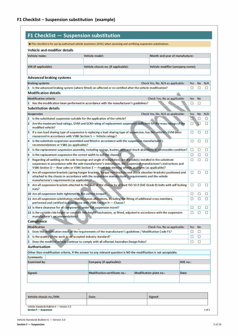
F1 Checklist – Suspension substitution (example)
Vehicle Standards Bulletin 6 — Version 3.0
Section F — Suspension 6 of 10
Modification Code F2 — Trailer suspension modifications
1. Scope Modifications covered under this code:
Covered • suspension modifications to heavy trailers where the basic trailer
type is not changed • trailer suspension modifications where a different suspension
system is substituted for the original. Not covered • modifications that alter the basic trailer type, e.g. semitrailer
conversion to dog trailer or pig trailer. Such trailers are deemed to be newly manufactured and must be certified as a new vehicle through the Road Vehicle Certification System. For more information about the certification of new vehicles, please refer to the Department of Infrastructure and Regional Development
• changes in the gross trailer mass (GTM) or aggregate trailer mass (ATM) of trailers (see VSB6 modification codes S7 and S12)
• relocating suspension systems (see VSB6 Modification Code H5). • chassis alterations including fitting of additional cross-members
(see VSB6 Modification Code H5).
2. Related standards Modified vehicles must comply with all ADRs, Australian Standards, acts and regulations. Below are some but not all of the areas that may be affected by the modifications in this code and require certification, testing or evidence to demonstrate compliance.
The certifier must ensure that the modified vehicle continues to comply with all related ADRs.
This… Must comply with… ATM re-rating VSB6 Modification Code S7 Trailer chassis modifications VSB6 Modification Code H5 Trailer brake system upgrading — non-standard
VSB6 Modification Code G3
Trailer brake system upgrading — standard
VSB6 Modification Code G8
3. Certification procedure The certification procedure for this modification code is as follows:
1. Modifier Determine if the modification is within manufacturer specifications. • If yes, the modification will need to be done in
accordance with manufacturer specifications. • If no, the modification will need to be done in
accordance with this modification code. 2. Modifier Consult with an accredited F2 AVE for guidance on
how to perform the modification. 3. Modifier Perform modification in accordance with AVE
advice and this code. 4. Modifier Organise approval inspection by an accredited F2
AVE. 5. F2 AVE Perform inspection, complete F2 checklist and
determine if compliance has been achieved. • If yes, proceed to step 6. • If no, do not proceed, advise modifier rework is
required to ensure compliance. Return to step 2.
6. F2 AVE Issue modification certificate, affix modification plate, and submit paperwork as required by the relevant AVE registration scheme.
AVEs must be satisfied that vehicle modification requirements are being met. It is advised that before modifications are carried out they are discussed with the certifying AVE.
4. Compliance requirements Because trailer and suspension manufacturers’ design preferences and production methods vary, the installation is likely to differ for the various makes or types of trailers and suspensions.
Required: • Ensure the modified trailer complies with all applicable ADRs, and
the requirements of the relevant heavy vehicle regulator and apply good engineering practice.
• Assess the impact of the suspension modification on braking performance and where necessary assess and certify the trailer to VSB6 modification codes G3 or G8.
• If the skid limits for the service brake application of the substitute suspension differ from those of the original suspension, conduct an analysis to confirm that it still complies with ADR 38/...
• Follow the manufacturer's instructions for installation if available, and if not available follow the guidelines outlined in this modification code.
• Where the modification renders the trailer identical to a trailer specification offered by the trailer manufacturer (including suspension, axle configuration, chassis design, braking system and kingpin to centre line of suspension dimension) then, other than certification of each modification to appropriate modification codes, no additional design and engineering evaluation of the modifications is needed.
Recommended: • Modify the trailer so that it is similar or identical to a trailer
offered by the trailer’s manufacturer if possible. If this is done, the design process, sourcing of components, evaluation and certification of the modification is likely to be simpler.
5. Design requirements Trailer mass rating requirements If modification of the suspension changes the trailer's GTM or ATM, it must be demonstrated that the trailer frame and braking system can accommodate this. These changes must be certified to the requirements of VSB6 Section S — Vehicle rating, Section G — Brakes, and Section H — Chassis, as applicable, and should be assessed to the manufacturer’s specification.
Required: • Ensure the suspension is designed for heavy trailer application
and is an approved load sharing suspension type (if applicable) as per the Commonwealth Road Vehicle Certification System and relevant heavy vehicle standards regulation.
• Ensure that the suspension and axle combination is suitable for the proposed mass rating of the modified trailer. Re-rating of the ATM, which is always required if the axle configuration is changed, is covered under VSB6 Modification Code S7.
• Ensure the attachment of suspension hangers to the trailer frame are adequate for all operating conditions and can accommodate high shock loads from poor road surfaces and loads from braking forces, in both forward and reverse directions.
• Ensure the suspension is suitable for the trailer’s chassis width.
Modification Code F2
Vehicle Standards Bulletin 6 — Version 3.0
Section F — Suspension 7 of 10
• Ensure the trailer’s slope (rake) suits its application and the coupling height.
• Ensure all trailer components have sufficient clearance from the suspension when it moves through its full range of travel.
• Ensure attachment points for axle catch straps or shock absorber mounts are adequate to support the mass of the axle plus any residual spring force.
• Ensure the configuration and mounting of brake components, brake chambers and chamber mounting brackets are suitable.
• Assess that chassis strength is adequate in accordance with VSB6 Modification Code H5.
• The braking system is re-certified under VSB6 modification codes G3 or G8.
• Do not allow shock absorbers to extend or bottom fully in the normal operation of the suspension.
Axle group requirements
Sliding Axle Assembly
Required: • Ensure that when fitting a sliding axle assembly the trailer and
assembly design is adequate for all likely operating loads. • Ensure the following for the sliding axle assembly design: − Fit a positive locking device to secure the assembly in fore and
aft positions. − Do not use air pressure to secure a lock in position. − Spring load the release mechanism so that it returns
immediately to the locked position when released. − Mount the release mechanism in a lockable box on the left
side of the trailer. − Display clear and concise operating instructions in an area
adjacent to the release control mechanism. • Fit permanent stops of adequate size to the trailer chassis to
prevent the axle assembly from detaching from the trailer. • Fit clearly visible or audible signalling devices to warn a driver in
the normal seated position of incorrectly adjusted or positioned locking devices.
Axle groups and spacing
Required: • Ensure all axle groups and the spacing of axles in each group are
conforming axle groups and are in accordance with the limits and requirements specified by the applicable in-service heavy vehicle regulator.
6. Installation requirements
Hanger bracket installation recommendations
Procedure
Recommended: • Locate the suspension’s forward hanger brackets on the chassis
at the required position to achieve the intended kingpin to suspension centre line dimension and axle spacing.
• Align the two forward hangers precisely square with the frame and in-line longitudinally and transversely, by measuring to the kingpin or front tow connection.
• Tack the forward two hangers in position to an accuracy of within ± 2 mm.
• Position next rearward hangers by measuring back from forward hangers and tacking them in position square to the frame.
Practice
Recommended: • Use the above steps to locate all subsequent hanger brackets. • Use low hydrogen consumables when welding hangar brackets to
the chassis. • Avoid welds transverse to the rail flange where possible. • Assemble the suspension in the hanger brackets in accordance
with the manufacturer's instructions, ensuring that all fasteners are correctly tightened.
Axle and spring assembly recommendations
Recommended: • Position spring seats on the axle at the correct spacing and
rotation so that spring mating faces are parallel with each other. • Place the centre of the centre-bolt hole at the top centre of the
axle housing. • Tack the spring seats in position. • Check clearances between the spring and axle equipment (such
as brake chambers or brake chamber brackets) with the springs in position on the axles.
• Remove the springs and weld the spring seats to the axle in accordance with the axle manufacturer's instructions.
• Use low hydrogen consumables. • Position the springs on the axle seats ensuring that any spacers
needed to accommodate the slope and camber of the trailer chassis are included.
• Align springs square to the axle and fasten and tighten them correctly.
Axle installation
Required: • Refer to VSB6 Section S — Vehicle rating before changing the
number of axles as it is likely to require a change in the GTM and ATM of the trailer.
Recommended: • Fit the axle and spring assembly into the hanger brackets. • Before aligning the axles, check the suspension is free and loose
in its rest position. • Check the alignment of the forward axle using specialist optical
alignment equipment or the following alignment check method.
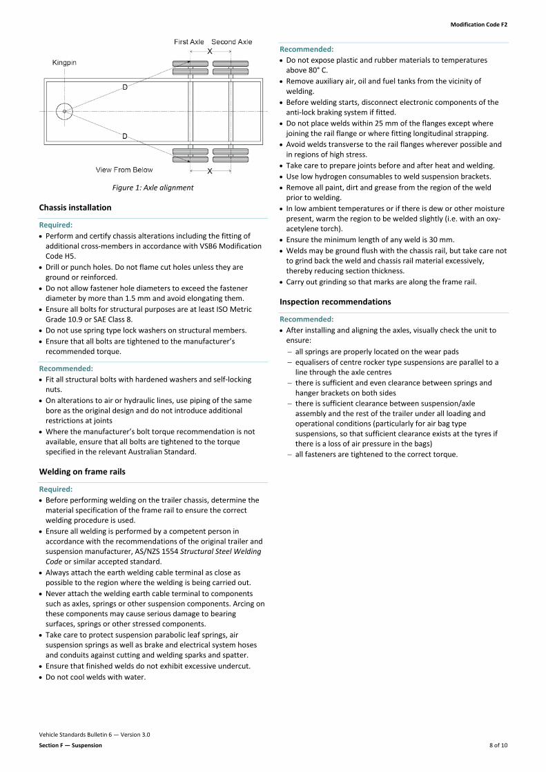
Alignment check method 1. Accurately measure the distance from the kingpin to the centre
line of the axle spindles on both sides (try to use spindle extensions for this).
2. Align the forward axle square to the kingpin or front towing attachment by changing the length of the adjustable radius rods, shimming the ends of fixed radius rods, or similar, as dictated by the design of the suspension.
3. Tighten the adjustment fasteners on the forward axle to the correct torque.
4. Align the next axle to the forward axle by measuring from centre lines of axle spindles on both sides and adjusting accordingly.
5. Align any other axles in the same manner.
Modification Code F2
Vehicle Standards Bulletin 6 — Version 3.0
Section F — Suspension 8 of 10
Figure 1: Axle alignment
Chassis installation
Required: • Perform and certify chassis alterations including the fitting of
additional cross-members in accordance with VSB6 Modification Code H5.
• Drill or punch holes. Do not flame cut holes unless they are ground or reinforced.
• Do not allow fastener hole diameters to exceed the fastener diameter by more than 1.5 mm and avoid elongating them.
• Ensure all bolts for structural purposes are at least ISO Metric Grade 10.9 or SAE Class 8.
• Do not use spring type lock washers on structural members. • Ensure that all bolts are tightened to the manufacturer’s
recommended torque.
Recommended: • Fit all structural bolts with hardened washers and self-locking
nuts. • On alterations to air or hydraulic lines, use piping of the same
bore as the original design and do not introduce additional restrictions at joints
• Where the manufacturer’s bolt torque recommendation is not available, ensure that all bolts are tightened to the torque specified in the relevant Australian Standard.
Welding on frame rails
Required: • Before performing welding on the trailer chassis, determine the
material specification of the frame rail to ensure the correct welding procedure is used.
• Ensure all welding is performed by a competent person in accordance with the recommendations of the original trailer and suspension manufacturer, AS/NZS 1554 Structural Steel Welding Code or similar accepted standard.
• Always attach the earth welding cable terminal as close as possible to the region where the welding is being carried out.
• Never attach the welding earth cable terminal to components such as axles, springs or other suspension components. Arcing on these components may cause serious damage to bearing surfaces, springs or other stressed components.
• Take care to protect suspension parabolic leaf springs, air suspension springs as well as brake and electrical system hoses and conduits against cutting and welding sparks and spatter.
• Ensure that finished welds do not exhibit excessive undercut. • Do not cool welds with water.
Recommended: • Do not expose plastic and rubber materials to temperatures
above 80° C. • Remove auxiliary air, oil and fuel tanks from the vicinity of
welding. • Before welding starts, disconnect electronic components of the
anti-lock braking system if fitted. • Do not place welds within 25 mm of the flanges except where
joining the rail flange or where fitting longitudinal strapping. • Avoid welds transverse to the rail flanges wherever possible and
in regions of high stress. • Take care to prepare joints before and after heat and welding. • Use low hydrogen consumables to weld suspension brackets. • Remove all paint, dirt and grease from the region of the weld
prior to welding. • In low ambient temperatures or if there is dew or other moisture
present, warm the region to be welded slightly (i.e. with an oxy-acetylene torch).
• Ensure the minimum length of any weld is 30 mm. • Welds may be ground flush with the chassis rail, but take care not
to grind back the weld and chassis rail material excessively, thereby reducing section thickness.
• Carry out grinding so that marks are along the frame rail.
Inspection recommendations
Recommended: • After installing and aligning the axles, visually check the unit to
ensure: − all springs are properly located on the wear pads − equalisers of centre rocker type suspensions are parallel to a
line through the axle centres − there is sufficient and even clearance between springs and
hanger brackets on both sides − there is sufficient clearance between suspension/axle
assembly and the rest of the trailer under all loading and operational conditions (particularly for air bag type suspensions, so that sufficient clearance exists at the tyres if there is a loss of air pressure in the bags)
− all fasteners are tightened to the correct torque.
Modification Code F2
Vehicle Standards Bulletin 6 — Version 3.0
Section F — Suspension 9 of 10
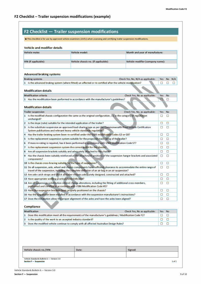
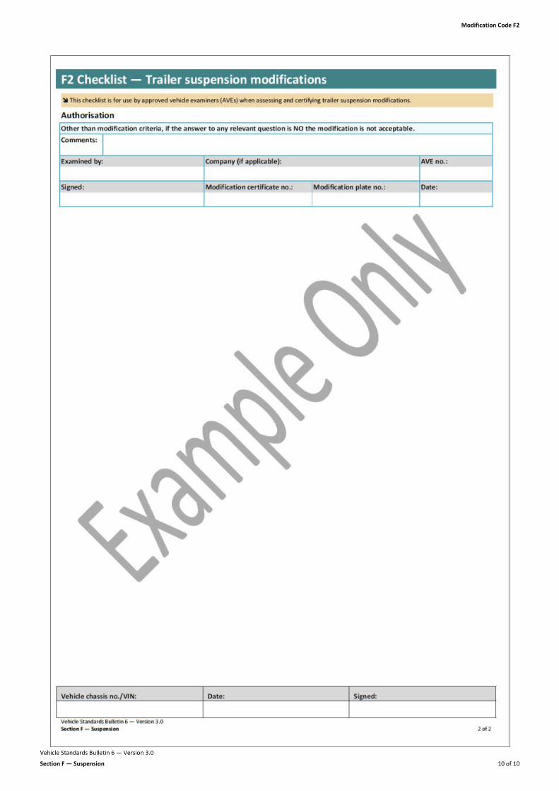
F2 Checklist – Trailer suspension modifications (example)
Modification Code F2
Vehicle Standards Bulletin 6 — Version 3.0
Section F — Suspension 10 of 10