Traction rectifier - Secheron€¦ · 2 TracTion recTifier / Dc power supply ... significant surge....
8
/ / / / / / SUBSTATIONS Traction rectifier DC power supply
Transcript of Traction rectifier - Secheron€¦ · 2 TracTion recTifier / Dc power supply ... significant surge....

////// SUBSTATIONS
Traction rectifier
DC power supply

TracTion recTifier / Dc power supply2
GENERAL INFORMATIONwith many years of experience in the field, sécheron is able to propose a reliable and suitable range of rectifiers for Dc traction power supply. our natural air cooled rectifiers are equipped with diode blocks with high overload capability and high blocking voltage.
The design of the rectifiers is based on ideally sized and proven semi-conductors (silicon diodes) offering particularly high performances and reliability. all components are fully interchangeable.
rectifiers are designed in accordance with customers specifications.
Thanks to its complete range of rated voltages, sécheron is able to cover all types of traction networks.
750
0 1.5 2.5 5 6 ...10
1500
3000
UN [VDC]
P [MW]
Customizedsolutions
TramwayTrolleybus
LRTAPMMonorail Subway
Commuter trainsMain line railwaysSubway
LRTMonorail
Commuter trainsMain line railways
Customizedsolutions
MAIN BENEFITSMAIN BENEFITS D compact design.
D adaptability: power connection from either the top or the bottom of the cubicle.
D ease of access for easy maintenance of components.
D reliable, robust and high quality solution.
D natural air cooling.
D High efficiency.

TracTion recTifier / Dc power supply 3
TRANSFORMER-RECTIFIER GROUPBased on a strong experience, sécheron provides an engineering and consulting support service for the transformers:
• specification.
• Monitoring during the manufacturing process with the supplier.
• assistance during factory acceptance test.
• assistance during the combined test of the complete transformer-rectifier group.
To ensure a good harmonization between rectifier and transformer, sécheron is able to provide the complete transformer-rectifier group.
STANDARDS
rectifiers are fully compliant and type tested according to standards iec 60146-1-1, iec 60747, en 50328 and ansi/ieee c34.2.
external characteristic for the double three phase bridge: connections 9 and 12 with K=1
external characteristic for the three phase bridge: connections 8, 9 and 12 with K=0

TracTion recTifier / Dc power supply4
RECTIFIER RANGE
3 PHASES BRIDGES IN SERIES OR PARALLEL CONNECTION
/// 6 PULSES up To 1500 VDc
(connection n°8 according to iec 60146-1-2)
/// 12 PULSES PARALLEL up To 1500 VDc, wiTHouT or wiTH ipT
(connection n°9 according to iec 60146-1-2)
/// 24 PULSES
2x transformer-rectifier groups each 12 pulses and with adequate phase shift ± 7.5° on primary can be provided to achieve 24 pulses rectification.
/// 12 PULSES SERIES up To 3000 VDc
(connection n°12 according to iec 60146-1-2)
Standard rectifier range
rated Dc voltage [V] 750 1500 3000
rated current [a] up to 6000 up to 4000 up to 3000
overload class Vi per en 50328 / iec 60146 (others on demand)
Max. ambient temperature [°c] 40 (without derating)
peak inverse voltage of diode [V] 2200 4500 4500
Max. altitude [m] 1000 (without derating)
ip degree ip2x to ip32
width [mm] 800 to 3200 800 to 3200 1200 to 2400
Depth [mm] 1400
Height [mm] 2200
Other ratings upon request.

TracTion recTifier / Dc power supply 5
PROTECTIONS
OVERVOLTAGE PROTECTION
SHORT-CIRCUIT PROTECTION
OVERLOAD PROTECTION
• Internal overvoltage: During turn-off, the load current of the diode does not stop flowing immediately but continues briefly in reverse direction as reverse recovery current. This peak reverse recovery current causes a voltage peak which is eliminated by an individual snubber circuit mounted in parallel with each diode.
• External overvoltage: The external overvoltage is essentially due to lightening strikes on the line and to short-circuits. The rectifier is equipped on the Dc side of a rc filter capable of absorbing a significant surge. a surge arrester can optionally be installed directly between the output terminals of the rectifier.
all traction rectifiers are designed to withstand external short circuit without damage until the MV circuit-breaker opens.
• Fuseless rectifiers: each branch has one diode only and the diode failure detection is ensured by the reverse current detector (cr10).
• Rectifiers with fuses (Np): composed of several parallel diodes on each branch, the failed diode will be isolated from the circuit by melting the associated fuse, witnessed by the fuses own micro-contact. after melting the fuse, the rectifier is withdrawn from operation.
• Rectifier in Np+1 configuration: additional diode in each branch in order to provide full performance after one failure diode in each branch.
• Rectifier in Np-1 configuration: The rectifier continues providing service with reduced performance after losing up to one diode in each branch; the performance is guaranteed for rated power and some reduced overload.
rectifier diodes are protected against overtemperatures by thermostats mounted on heatsinks (alarm and trip thresholds).
10 ms
1
2
3
4
5
6
7
8
9
100 ms 1 s 1 min 2 hTime
Ove
rcur
rent
to r
ated
cur
rent
Load limit curve of rectifier
Thermal protection
Load capacity curve
Overcurrent time protection
Overload class of rectifier
I>>>
I>>
I>
TracTion recTifier / Dc power supply6
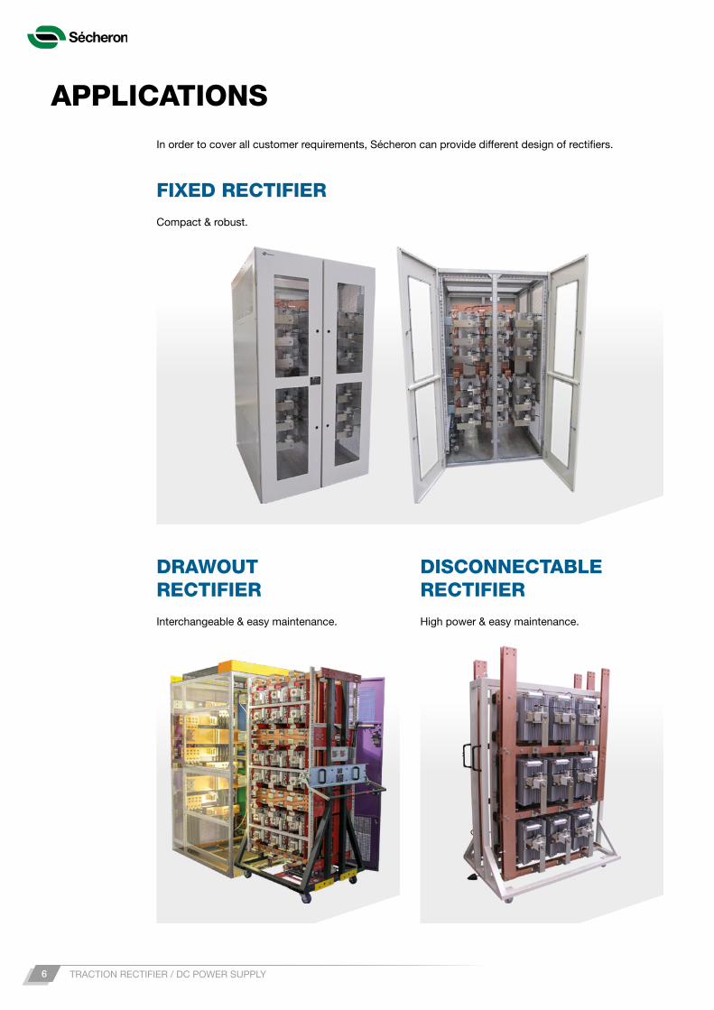
APPLICATIONSin order to cover all customer requirements, sécheron can provide different design of rectifiers.
compact & robust.
interchangeable & easy maintenance. High power & easy maintenance.
FIXED RECTIFIER
DRAWOUT RECTIFIER
DISCONNECTABLE RECTIFIER

TracTion recTifier / Dc power supply 7
sécheron also offers a cubicle which integrates both functions of rectifier (up to 1200 kw) and isolating switch for special applications for light rails (compact solution for tramway and trolley-bus).
RECTIFIER WITH INSULATING SWITCH
Reverse current detection
RC Filtercombined with base-load resistor
Frame leakage detectionframe-earth current threshold relay
Optional: Voltage Limiting Devicenegative-earth voltage threshold relay
Power diode blocksDiodes fitted in heatsinks combinedwith snubbers and optional fuses
MIU10 & VM10/12isolated amplifiers for currentand voltage measurement
SWS / SWGBipolar off-load motorized disconnecting switch with optional earthing connection
Optional: IPTinterphase coil for connection withcoupled rectifier-transformers
SPECIAL APPLICATIONUPON REQUEST
CONTROLLED RECTIFIER
Customer benefits:
D regulation of the voltage of the line in order to compensate voltage drops.
D optimization of the functioning in case of double converter (controlled rectifier coupled with inverter).

Sécheron SA
Rue du Pré-Bouvier 251242 Satigny - Geneva
CH-Switzerland
www.secheron.com
Tel: +41 (0)22 739 41 11Fax: +41 (0)22 739 48 [email protected]
This document is not contractual and contains information corresponding to the level of technology at the date of printing. Sécheron reserves the right to modify and/or improve the product, whose characteristics are described in these documents, as required by new technology at any time. It is the purchaser’s responsibility to inform himself, no matter what the circumstances, of
the product’s maintenance conditions and requirements. Sécheron reserves all rights, especially those arising from our “General Delivery Conditions”.
Copyright© 2016 Sécheron SA
sG825863Ben_c00-09.16