TracPhone V7 Installation Guide (60 cm Configuration) · Installation Guide TracPhone ® V7 24" (60...
32
Installation Guide TracPhone ® V7 24" (60 cm) Configuration
Transcript of TracPhone V7 Installation Guide (60 cm Configuration) · Installation Guide TracPhone ® V7 24" (60...

Installation Guide
TracPhone® V724" (60 cm) Configuration

RF Cable Connectors
1
Addendum
PLEASE READ!Important Addendum to Your Product Manual
A small packet of silicone grease is supplied in the kitpack. Apply this grease to the inner body of all RF cable connectors that you connect to the KVH antenna and any inline feed-thru adapters above deck. This grease will help prevent moisture from seeping into or forming inside the connector and protect the center conductor from corrosion.
Figure 1 Silicone Grease
Directions for UseWhen connecting RF cables above deck to the KVH antenna, as well as to any inline feed-thru adapters, follow the steps below to protect and seal each connection:
1. Clean and dry the male connector on the RF cable and the female connector on the antenna or feed-thru adapter.
2. Fill half of the inner body of the RF cable’s connector with silicone grease. Connecting the cable in the next step will displace the grease to fill the entire space within the connector.
3. Connect and SLOWLY hand-tighten the RF cable to the antenna or feed-thru adapter, allowing the grease to diffuse and settle into the entire connector body.
4. Make sure the RF cable’s connector is tightened all the way into the female connector of the antenna or feed-thru adapter. Then tighten the connection with a 7/16" torque wrench set to 15 in.-lbs.
5. Wipe off any excess grease from the outside of the connector.
6. Seal the connection with silicone sealant, self-vulcanizing tape, or equivalent. If using self-vulcanizing tape, be sure to wrap the tape CLOCKWISE around the connector (the same direction in which you tightened the connector). Wrapping the tape in the opposite direction will result in tension that might loosen the connector over time.
The procedure is complete.
54-0779 Rev. A
mnelson
Text Box
This addendum applies to products with antenna serial number 110601833 or later.
TracPhone V7 Installation Guide
1
KVH’s Complete mini-VSAT Broadbandsm System
KVH, TracPhone, and the unique light-colored dome with dark contrasting baseplate are registered trademarks of KVH Industries, Inc. All other trademarks are property of their respective companies. The information in this document is subject to change without notice.
No company shall be liable for errors contained herein. © 2008-2011 KVH Industries, Inc., All rights reserved. 54-0464 Rev. FU.S. Patent Pending
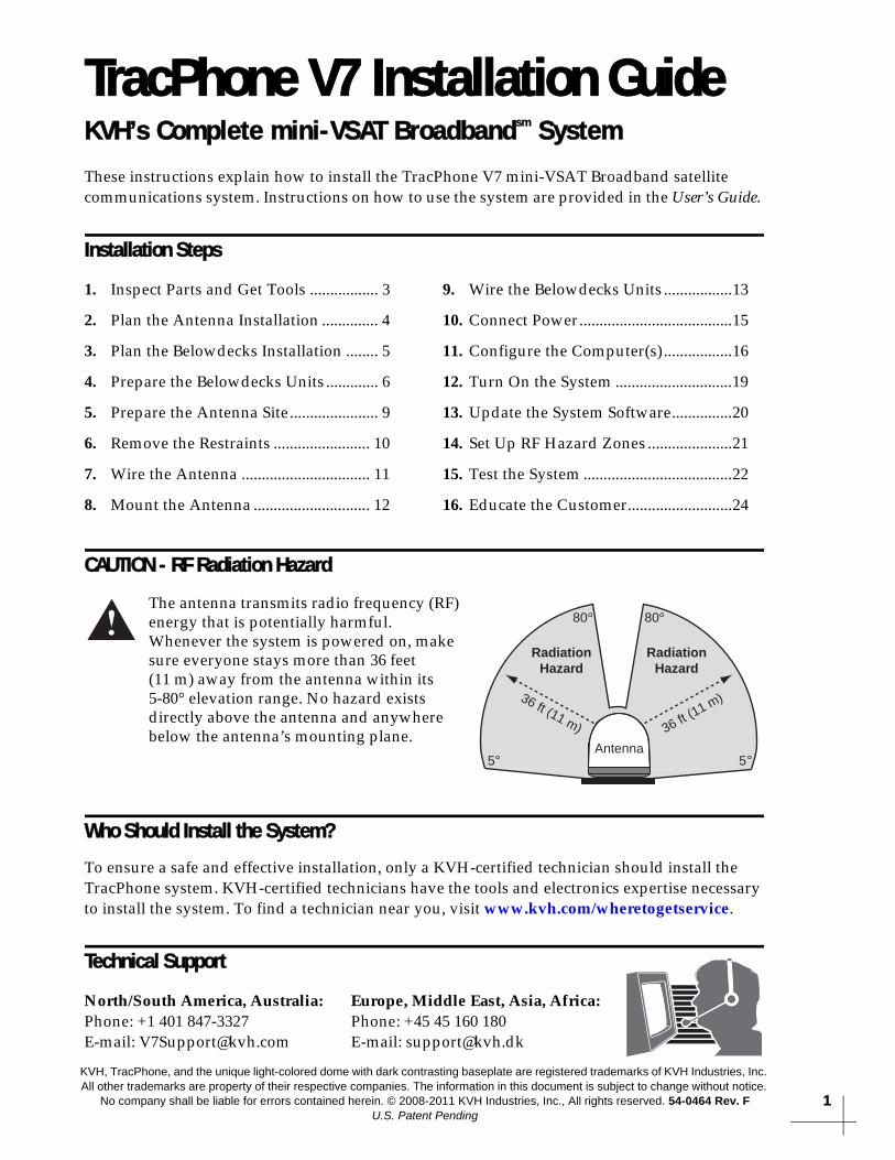
These instructions explain how to install the TracPhone V7 mini-VSAT Broadband satellite communications system. Instructions on how to use the system are provided in the User’s Guide.
Installation Steps
CAUTION - RF Radiation Hazard
Who Should Install the System?
To ensure a safe and effective installation, only a KVH-certified technician should install the TracPhone system. KVH-certified technicians have the tools and electronics expertise necessary to install the system. To find a technician near you, visit www.kvh.com/wheretogetservice.
Technical Support
1. Inspect Parts and Get Tools ................. 3
2. Plan the Antenna Installation .............. 4
3. Plan the Belowdecks Installation ........ 5
4. Prepare the Belowdecks Units ............. 6
5. Prepare the Antenna Site...................... 9
6. Remove the Restraints ........................ 10
7. Wire the Antenna ................................ 11
8. Mount the Antenna ............................. 12
9. Wire the Belowdecks Units .................13
10. Connect Power......................................15
11. Configure the Computer(s).................16
12. Turn On the System .............................19
13. Update the System Software...............20
14. Set Up RF Hazard Zones .....................21
15. Test the System .....................................22
16. Educate the Customer..........................24
The antenna transmits radio frequency (RF) energy that is potentially harmful. Whenever the system is powered on, make sure everyone stays more than 36 feet (11 m) away from the antenna within its 5-80° elevation range. No hazard exists directly above the antenna and anywhere below the antenna’s mounting plane.
North/South America, Australia:Phone: +1 401 847-3327E-mail: [email protected]
Europe, Middle East, Asia, Africa:Phone: +45 45 160 180E-mail: [email protected]
RadiationHazard
RadiationHazard
36 ft (11 m)36 ft (11 m)
80
5
80
5Antenna

3
Radome
Baseplate
Figure 1: TracPhone V7 System Components
Antenna
Control Unit
Modem
Ethernet Switch
Remote Service& Support Module
Multimedia TerminalAdapter (MTA)
Inspect Parts and Get Tools1
Before you begin, follow these steps to make sure you have everything you need to complete the installation.a. Unpack the box and ensure it contains everything shown in Figure 1 and on the Kitpack Content Lists. Save the packaging for future use.
b. Carefully examine all of the supplied parts to ensure nothing was damaged in shipment.
c. Gather all of the following tools and materials that you will need:
• Flat-head and Phillips-head screwdrivers
• Electric drill and 1/2" (13 mm) bit
• 3" (80 mm) hole saw
• Wire cutters
• Socket wrenches and extension and
• 7/16" open-end wrench
• Silicone sealant or self-vulcanizing tape
• Light hammer and center punch
• Adhesive tape and scriber or pencil
• Wire strippers and terminal lug crimper
• Two RF coax cables and F-connector installation tools (see page 11)
• Isolation transformer, if required (see page 15).
• Windows® 7, Vista™, or XP laptop with the latest version of TPV7 Flash Update Wizard installed (software available to technicians on the KVH Partner Portal)
NOTE: KVH offers the optional KVH CommBox™ for connecting multiple communication systems to the onboard local area network (LAN), providing least cost routing, firewall, bandwidth management, web caching, and optimization features (KVH part #72-0470 (compact) or #72-0472 (rack-mount)).
Always lift the antenna by the baseplate and never by the radome or any portion of the internal antenna assembly (see Figure 1).
IMPORTANT!

4
Blocked!
Antenna
Mast
Look Angle
Vessel Platform
5° to 80°
Figure 2: Blockage from Obstruction
27.36"(69.5 cm
)
26.2"(66.5 cm)
12"(30.5 cm)
12"(30.5 cm)
6"(15.2 cm)
6"(15.2 cm)
4 x Ø1/2"(Ø13 mm)
26.2"(66.5 cm)
FWD
Figure 3: Antenna Dimensions
Side View
Bottom View
Plan the Antenna Installation
Before you begin, consider the following antenna installation guidelines:• Minimize blockage. The antenna requires a clear view of the sky to transmit and receive satellite signals (see Figure 2). The fewer obstructions, the better the system will perform.
• Make sure the mounting surface is wide enough to accommodate the antenna’s base (see Figure 3). Also make sure it is flat, level, strong enough to support the antenna’s weight (60 lbs, 27.2 kg), and rigid enough to withstand heavy vibration.
• Select a location that is as close as possible to the intersection of the vessel’s centerline and midships.
• Select a location that is well above any areas accessible to passengers and crew to reduce the risk of RF radiation exposure.
• Avoid placing the antenna near any magnetic compasses or other onboard antennas to prevent potential interference.
Do not mount the antenna at the same level as the radar because the radar’s energy might overload the antenna and damage its internal components. Ideally, you should mount the antenna 4 ft (1.2 m) above the radar, outside the beam path of the radar.
IMPORTANT!
2

5
11.31"(28.7 cm)
2.61"(6.6 cm)
16.75"(42.5 cm)
Figure 4: Control Unit or Modem Dimensions (Identical)
20.5"(52.1 cm)
11.3"(28.7 cm)
20.5"(52.1 cm)
Figure 5: Case Dimensions
Figure 6: Dimensions of Ancillary Components
Component Dimensions (W x D x H)
Switch 6.7" x 3.9" x 1.1"(17 cm x 9.9 cm x 2.8 cm)
MTA 4.6" x 5.12" x 1.18"(11.7 cm x 13 cm x 3 cm)
Remote Service & Support Module
5.12" x 3.54" x 1.5"(13 cm x 9 cm x 3.8 cm)
Plan the Belowdecks Installation
Before you begin, consider the following installation guidelines for the belowdecks units.Control Unit and Modem• Select a mounting location in a dry, well-
ventilated area belowdecks away from any heat sources or salt spray.
• Be sure the front panels will be easily accessible to the user.
• Leave enough room at the rear panel to accommodate the connecting cables.
• You have several options for mounting the control unit and modem:
Option 1 - Inside the optional case
Option 2 - To a horizontal surface together using two L-brackets
Option 3 - To a horizontal surface separately using four L-brackets
NOTE: The control unit and modem are sized to fit a standard 19" (482.6 mm) equipment rack.
• To use the supplied data and power cables, the control unit must be located within 100 ft (30 m) of the antenna. However, you can order 150 ft (45 m) cables if a longer cable run is necessary (see Figure 18 on page 11).
Switch and MTA• To use the supplied Ethernet cables, select a
mounting location within 25 ft (7.5 m) of the modem (maximum length = 200 ft (60 m)).
• If you install a wireless access point (supplied by customer), be sure the location provides adequate WiFi reception. Do not install it in an area surrounded by metal or near any electrical devices that emit RF noise.
Remote Service & Support Module• To use the supplied serial data cable, select a
mounting location within 25 ft (7.5 m) of the control unit (maximum length = 50 ft (15 m)).
• Be sure the location provides adequate GPRS cellular reception.
3

6
M4 x 16mm Screw (x4)
Mounting Bracket (x2)
Top Cover
Bottom Cover
M4 x 12mm Screw (x4)
Plastic Foot (x4)
123456789
101112
Figure 7: Assembling the Case
#6 Washer (x4)#6-32 Screw (x4)
Strain-ReliefBracket
Tie-WrapHoles (x12)
RetainingStrap (x2)
Control Unit
Modem
Figure 8: Attaching the Strain-Relief Bracket
M6 Screw (x4)Plastic Washer (x4)
#6 Washer (x4)#6-32 Screw (x4)
“Z” Bracket (x2)Cage Nut (x4)
Attach to Case
Attach to Control Unit
M6 Screw (x8)Plastic Washer (x8)
Cage Nut (x8)Blank Panel
Control Unitand Modem
Case
Figure 9: Securing the Control Unit/Modem in the Case
Prepare the Belowdecks UnitsOption 1 - Mounting in the Case
If you plan to mount the control unit and modeminside the optional 19" (482.6 mm) case, follow these steps to assemble the case.
a. Remove the four M4 screws securing the rear cover to the case. Discard the rear cover.
b. Attach the top cover to the case using four M4 x 12 mm screws (see Figure 7). Attach the bottom cover and the two mounting brackets using four M4 x 16 mm screws.
c. Attach the four plastic feet to the bottom cover (see Figure 7).
d. At the front of the case, insert eight cage nuts into the following locations on the frame (four on each side) (see Figure 7): #2, #5, #8, and #11.
e. At the back of the case, insert four cage nuts into the following locations on the frame (two on each side): #1 and #3.
f. Remove the four #6-32 screws and washers securing the two retaining straps to the rear panel of the control unit. Do not remove the bottom screws securing the straps to the modem.
g. Attach the strain-relief bracket to the retaining straps and control unit using the screws and washers you removed in Step f (see Figure 8).
h. At the top 3U section of the case, insert the control unit/modem assembly and secure the front mounting brackets to the case using four M6 screws and washers (see Figure 9).
i. At the bottom 3U section of the case, attach the supplied blank panel using four M6 screws and washers (see Figure 9).
j. Secure the back of the control unit to the back of the case using the two supplied “Z” brackets. Attach the brackets to the case frame using four M6 screws and washers. Attach the brackets to the rear panel of the control unit using four #6-32 screws and washers (see Figure 9).
k. Once you have completed all system wiring, mount the case to the vessel using fasteners appropriate for the mounting surface.
4

Figure 10: Attaching the Strain-Relief Bracket
#6 Washer (x4)#6-32 Screw (x4)
Strain-ReliefBracket
Tie-WrapHoles (x12)
RetainingStrap (x2)
Control Unit
Modem
#6 Washer (x4)#6-32 Screw (x4)
Bracket (x2)
Control Unit
Modem
Ø.156" (Ø3.96 mm)Mounting Hole (x4)
Figure 11: Attaching the Mounting Brackets
Prepare the Belowdecks UnitsOption 2 - Mounting Units Together
If you plan to mount the control unit and modemtogether as an assembly, without using the optional case or an equipment rack, follow these steps to attach the strain-relief bracket and “L” mounting brackets.
a. Remove the four #6-32 screws and washers securing the two retaining straps to the rear panel of the control unit. Do not remove the bottom screws securing the straps to the modem.
b. Attach the strain-relief bracket to the retaining straps and control unit using the screws and washers you removed in Step a (see Figure 10).
c. Attach two of the supplied “L” mounting brackets to the sides of the control unit or modem using four #6-32 screws and washers (see Figure 11). You can attach the brackets to either the top of the control unit or the bottom of the modem, depending on your desired mounting location.
d. Once you have completed all system wiring, mount the modem/control unit assembly to the vessel using fasteners appropriate for the mounting surface.
4
7

8
#6-32 Screw (x28)
#6 Washer (x28)
Bracket (x2)
Strap (x4)
Control Unit
Modem
Figure 12: Detaching the Control Unit from the Modem
#6 Washer (x4)
#6-32 Screw (x4)
Strain-ReliefBracket
Tie-wrapHoles (x12)
Control Unit
Figure 13: Attaching the Bracket to the Control Unit
#6 Washer (x4)#6-32 Screw (x4) Strain-Relief
Bracket
Tie-wrapHoles (x12)
Modem
Figure 14: Attaching the Bracket to the Modem
Prepare the Belowdecks UnitsOption 3 - Mounting Units Separately
If you plan to mount the control unit and modemseparately, follow these steps to detach the control unit from the modem, attach the strain-relief brackets, and attach the “L” mounting brackets.
a. Remove the 28 #6-32 screws and washers securing the two rack-mount brackets and four metal retaining straps to the control unit and modem (see Figure 12). Remove the brackets and straps.
b. Attach a strain-relief bracket to the back of the control unit using four of the screws and washers you removed in Step a (seeFigure 13).
c. Attach a second strain-relief bracket to the back of the modem using four of the screws and washers you removed in Step a (see Figure 14).
d. Attach two of the supplied “L” brackets to the sides of the control unit using four #6-32 screws and washers (see Figure 11 on page 7). You can attach the brackets at either the top or bottom of the control unit, depending on your desired mounting location.
e. Attach the two other supplied “L” brackets to the sides of the modem using four #6-32 screws and washers (see Figure 11 on page 7). You can attach the brackets at either the top or bottom of the modem, depending on your desired mounting location.
f. Once you have completed all system wiring, mount the control unit and modem to the vessel using fasteners appropriate for the mounting surface.
4

12"(305 mm)
Ø1/2" (Ø13 mm)Mounting Hole (x4)
12"(305 mm)
Ø3" (Ø80 mm)Cable Access Hole
FWD
Foam Seal
Figure 15: Antenna Mounting Holes Layout
Prepare the Antenna Site
Once you have identified a suitable antenna mounting site, according to the guidelines provided in Step 2, follow these steps to drill the mounting holes and cable access hole to prepare the site for installation.a. Unfold the antenna mounting template (supplied in the Customer Welcome Kit) and place it onto the mounting surface. Make sure the “FWD” (forward) arrow points toward the bow and is parallel to the vessel’s centerline (see Figure 15).
NOTE: You don’t need to mount the antenna exactly on the vessel’s centerline, but the antenna’s forward arrow must be parallel to it.
b. Using a light hammer and center punch, mark the locations for the four mounting holes and cable access hole on the mounting surface in the locations indicated on the template.
c. Drill a 1/2" (13 mm) hole at the four mounting hole locations you marked in Step b. Later, you will insert four 3/8"-16 bolts through these holes to secure the antenna to the mounting surface.
d. Cut out the 3" (80 mm) cable access hole in the location you marked in Step b. Smooth the edges of the hole to protect the cables. Later, you will route the data, power, and RF cables through this hole and into the vessel.
e. Clean and dry the antenna mounting surface.
f. Peel off the paper backing from the supplied foam seal to expose the adhesive. Then press the foam seal down firmly onto the mounting surface, ensuring the hole in the foam seal aligns with the cable access hole in the mounting surface (see Figure 15).
NOTE: Apply the foam seal to the vessel mounting surface, not to the antenna’s baseplate. You will have difficulty connecting the cables to the antenna if the foam seal is attached to the baseplate.
5
9
1
#10-32 Screw (x6)
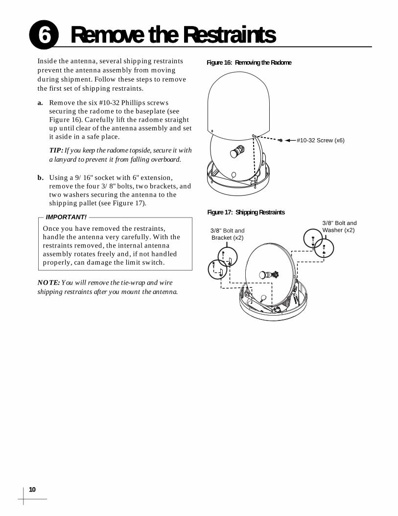
Figure 16: Removing the Radome
3/8" Bolt andWasher (x2)3/8" Bolt and
Bracket (x2)
Figure 17: Shipping Restraints
Remove the Restraints
Inside the antenna, several shipping restraints prevent the antenna assembly from moving during shipment. Follow these steps to remove the first set of shipping restraints.a. Remove the six #10-32 Phillips screws securing the radome to the baseplate (see Figure 16). Carefully lift the radome straight up until clear of the antenna assembly and set it aside in a safe place.
TIP: If you keep the radome topside, secure it with a lanyard to prevent it from falling overboard.
b. Using a 9/16" socket with 6" extension, remove the four 3/8" bolts, two brackets, and two washers securing the antenna to the shipping pallet (see Figure 17).
NOTE: You will remove the tie-wrap and wire shipping restraints after you mount the antenna.
Once you have removed the restraints, handle the antenna very carefully. With the restraints removed, the internal antenna assembly rotates freely and, if not handled properly, can damage the limit switch.
IMPORTANT!
6
0

11
Figure 18: RF Cable Requirements*
* For alternate cable options, see the Application Notes section of the KVH Partner Portal (technicians only).
15-50 ft (5-15 m) Cable Run
Cable: RG-11
Connector: SNS11ASInstallation Tools: CST596711 and L3011B
51-100 ft (16-30 m) Cable Run
Cable: LMR-400-75
Connector: EZ-400-FMH-75Installation Tools: TK-400EZ-75
101-150 ft (31-45 m) Cable Run
Cable: LMR-600-75
Connector: EZ-600-FMH-75Installation Tools: TK-600EZ
0.25" (6.35 mm)0.5" (12.7 mm)
0.064" (1.63 mm) dia.
0.170" (4.32 mm)0.344" (8.74 mm)
0.065" (1.65 mm) dia.
0.610" (15.49 mm)
0.250" (6.35 mm)0.370" (9.40 mm)
0.108" (2.74 mm) dia.
0.870" (22.10 mm)
NOTE: Optional 150 ft (45 m) data and power cables:Data cable KVH part #32-0921-0150Power cable KVH part #32-0924-0150
NOTE: RG-11 connectors/tools are manufactured by Thomas & Betts. LMR-400-75 and LMR-600-75 cables/connectors/tools are manufactured by Times Microwave.
MRx
MTx
Figure 19: Connectors on Bottom of Antenna
Wire the Antenna
Follow these steps to connect the data, power, and RF cables to the antenna.a. In addition to the data and power cables, you will need to connect two 75 RF coax cables from the antenna to the belowdecks equipment. Use the guidelines in Figure 18 to determine the type of RF cables required.
b. Label both ends of the two RF cables. Label one cable “TX,” and label the other “RX.”
c. Route the data, power, and RF cables belowdecks through the 3" (80 mm) cable access hole. Leave an adequate service loop, approximately 8" (20 cm) of slack, in the cables for easy serviceability. Later, you will connect the data and power cables to the control unit and the RF cables to the modem.
d. Connect the data cable to the “Data” jack on the bottom of the antenna (see Figure 19). Hand-tighten until the connector locks in place; do not use excessive force.
e. Connect the power cable to the “Power” jack on the bottom of the antenna. Hand-tighten until the connector locks in place; do not use excessive force.
f. Connect the RF cable labeled “TX” to the “MTx” jack on the bottom of the antenna. Hand-tighten, then tighten with a 7/16" wrench for 1/4 turn to ensure a good electrical connection.
g. Connect the RF cable labeled “RX” to the “MRx” jack on the bottom of the antenna. Hand-tighten, then tighten with a 7/16" wrench for 1/4 turn.
h. Seal both RF cable connections with silicone sealant, self-vulcanizing tape, or equivalent.
Terminate RF cables with the proper type “F” connectors (see Figure 18). Instructions for terminating LMR-400-75 cable are provided in Appendix B on page 28.
IMPORTANT!
7

1
Figure 20: Forward Arrow in Antenna Baseplate
3/8"-16 Bolt (x4)
3/8" Flat Washer (x4)
Rubber Foot (x4)
Mounting Surface
3/8" Flat Washer (x4)
3/8"-16 Hex Nut (x4)
Antenna Baseplate
3/8" Shoulder Washer (x4)
3/8" Lock Washer (x4)
3/8" Shoulder Washer (x4)Preinstalled
Figure 21: Mounting the Antenna (Side View)
IMP
OR
TAN
T
Wire
Tie-wrap
IMPO
RTA
NT
REMOVE T
HIS S
HIPPIN
G
RESTRAIN
T BEFO
RE OPERAT
ING
Figure 22: Shipping Restraints
Mount the Antenna
2
Follow these steps to mount the antenna to the mounting surface.
a. Place the antenna baseplate over the holes drilled in the mounting surface.
b. Make sure the forward arrow in the baseplate points toward the bow and is parallel to the vessel’s centerline (see Figure 20).
c. Make sure the four holes in the baseplate line up with the four holes in the mounting surface.
d. At each of the four baseplate mounting holes, place a 3/8" flat washer on a 3/8"-16 bolt and insert the bolt into the hole (with preinstalled 3/8" shoulder washer) from above (see Figure 21).
e. Secure each mounting bolt to the mounting surface using a 3/8" shoulder washer, a 3/8" flat washer, a 3/8" lock washer, and a 3/8"-16 hex nut from below. Tighten all four bolts until the four rubber feet on the baseplate are bottomed against the mounting surface and the foam seal is fully compressed. KVH recommends that you tighten the nuts to between 12 and 16 ft-lbs (16.2 and 21.7 N-m) of torque.
f. Using wire cutters, cut and remove the shipping restraint securing the reflector to the antenna frame (see Figure 22).
g. Cut and remove the tie-wrap shipping restraint securing the antenna’s LNB to the back of the reflector (see Figure 22).
h. Reinstall the radome onto the antenna. Secure in place with the six #10-32 screws you removed in Step 6a (see Figure 16 on page 10).
i. Install a protective plastic cap (supplied in the kitpack) over each radome screw.
You will need to rotate the antenna assembly by hand to see all four mounting holes. Rotate the antenna assembly slowly. If it hits a mechanical stop with excessive force, the limit switch might become damaged.
IMPORTANT!
8

1 2 11109876 12543
Data
Power
Antenna
Blue/White
White/Blue
Brown/White
White/Gray
Gray/White
White/Orange
Orange/White
White/Brown
Red
Black
Terminal Strip Connector
Figure 23: Antenna Power and Data Wiring
198765432
121110
Control Unit
Terminal StripConnector
Antenna
Figure 24: Antenna Power and Data Wiring
Antenna
MRx
J1AC PWR
J3Rx RF
J2Tx RF
J4ACU
J5CONSOLE
J6BUC PWR J8
USERENET
J7ACUENET
MODEL: VMBR-1510 ArcLightPART: 1234567 REV XXXSERIAL: XX-XXXXXXCAGE CODE: 12345
Modem
MTx
TxRFRxRF
Figure 25: Antenna RF Transmit and Receive Wiring
Wire the Belowdecks Units
Wire the Antenna CablesFollow these steps to connect the antenna to the control unit and the modem.NOTE: A system wiring diagram is provided in Appendix A on page 27.
a. First dress the data and power cables from the antenna. Strip back the insulation of each wire approximately 1/4" (6 mm) and gently twist each wire to ensure a good electrical connection.
b. Find the terminal strip connector in the kitpack. Connect the antenna data cable to the terminal strip connector as shown in Figure 23.
c. Connect the power cable from the antenna to the terminal strip connector as shown in Figure 23.
d. Plug the terminal strip connector into the rear panel of the control unit (see Figure 24).
e. Connect the RF coax cable labeled “RX” (connected to the antenna’s MRx jack) to the “Rx RF” jack on the back of the modem (see Figure 25).
f. Connect the RF coax cable labeled “TX” (connected to the antenna’s MTx jack) to the “Tx RF” jack on the back of the modem.
The diagram refers to wires by body color/stripe color. For example, “Brown/White” means the brown wire with the white stripe.
IMPORTANT!
Be sure to terminate RF cables properly with type “F” connectors.
IMPORTANT!
9
13

1
MODEMRS422
BUC POWER20V 2.5A
J1AC PWR
J3Rx RF
J2Tx RF
J4ACU
J5CONSOLE
J6BUC PWR J8
USERENET
J7ACUENET
NO OPERATORSERVICEABLEPARTS INSIDE,DO NOT OPEN
CAUTION
MODEL: VMBR-1510 ArcLightPART: 1234567 REV XXXSERIAL: XX-XXXXXXCAGE CODE: 12345
Wir
e C
olo
rs:
Bo
dy/S
trip
e
Control Unit
Modem
Modem
ACU
BUC Power
BUC Pwr
Figure 26: Modem Data and BUC Power Wiring
SerialGP10
Antenna On/Off AudioSIM
Power
Control Unit
Remote Service& Support Module
CellularAntenna
Maintenance Port
Serial
Antenna
Figure 27: Remote Service & Support Module Wiring
J4ACU
J5CONSOLE
J6BUC PWR J8
USERENET
J7ACUENET
NO OPERATORSERVICEABLEPARTS INSIDE,DO NOT OPEN
CAUTION
Modem
MTA
4 3 2 18 7 6 5
POE 48V
+
Switch
12V DC RSTR WAN LAN PHONE 2 PHONE 1
LaptopPC
Phone1
User ENet
WAN
5
AnalogPhone
67
PoE portsfor optionaldevices
Figure 28: Switch and MTA Wiring
Continued Wire the Belowdecks Units
NOTE: The Ethernet and VoIP equipment supplied with the system might differ from those shown in this diagram.
4
Wire the Control Unit to the ModemFollow these steps to connect the control unit to the modem.
a. Connect a serial data cable from the “Modem” jack on the control unit to the “ACU” jack on the modem (see Figure 26).
b. Connect the BUC power cable from the “BUC Power” jack on the control unit to the “BUC Pwr” jack on the modem.
Wire the Remote Service ModuleFollow these steps to connect the remote service & support module to the control unit.
a. Connect a serial data cable from the “Maintenance Port” jack on the control unit to the “Serial” jack on the remote service & support module. (see Figure 27).
b. Make sure the cellular antenna is connected to the “Antenna” jack on the remote service & support module.
Wire the Switch and MTAFollow these steps to connect all LAN devices.
a. Connect the supplied straight-through Ethernet cable from the “User ENet” jack on the modem to any port on the switch (see Figure 28).
b. Connect a second straight-through Ethernet cable from any port on the switch to the “WAN” jack on the MTA.
c. Connect the customer’s analog (not digital) phone(s), fax machine, and/or PABX to the desired RJ-11 “Phone” jack(s) on the MTA. Each jack is linked to a unique phone line.
NOTE: If the customer requires an enterprise-grade fax solution, install KVH’s optional UCH-250 Fax Server (KVH part #19-0520).
d. For a wired Ethernet network, connect the customer’s computer(s) to any port(s) on the switch. For a wireless network, connect an access point (customer-supplied) to the switch (ports 1-4 support IEEE 802.3af devices).
9

15
Ground
NeutralN
100-240 VAC
TracPhone V7 Equipment Isolation Transformer
60-220 VAC
60-220 VAC
Ground
ShipboardTwo-Phase,Split-Phase,
or Delta Power
Single-PhasePower Input
Figure 29: Single-Phase AC Power Input
NOTE: Ground fault protection devices cannot detect faults behind an isolation transformer.
Vessel AC Power115 or 230 VACSingle-Phase
J1AC PWR
J3Rx RF
J2Tx RF
J4ACU
J5CONSOLE
J6BUC PWR J8
USERENET
J7ACUENET
NO OPERATORSERVICEABLEPARTS INSIDE,DO NOT OPEN
CAUTION
MODEL: VMBR-1510 ArcLightPART: 1234567 REV XXXSERIAL: XX-XXXXXXCAGE CODE: 12345
Antenna On/Off AudioSIM
Power
PowerStrip
AC/DCAdapter
4 3 2 18 7 6 5
POE 48V
+
12V DC RSTR WAN LAN PHONE 2 PHONE 1
Control Unit
Modem
Remote Service Module
MTA
AC/DCAdapter
Switch
AC/DCAdapter
AC Input
12 VDC
48V
AC Pwr
Power
Figure 30: Power Wiring
Connect Power
Follow these steps to connect power to the TracPhone V7 system.a. Before you begin, disconnect vessel power and be sure the vessel is properly grounded in accordance with marine standards.
b. Connect the control unit and modem to the supplied AC power strip using the adapter cables provided in the kitpack (see Figure 30).
c. Strain-relieve all wires at the back of the control unit and modem by securing them to the attached strain-relief bracket(s) using tie-wraps. Leave enough slack for serviceability.
d. Connect the appropriate power cord (US or European) to the power strip. Then plug it into the vessel’s 115 or 230 VAC supply. Also connect the MTA, switch, and remote service & support module to AC power via their AC/DC adapters (see Figure 30).
WARNING
The TracPhone system requires 3-wire single-phase AC power (hot, neutral, and ground). Voltage between hot-neutral and hot-ground should each measure between 100-240 VAC.
Some large ships use two-phase, split-phase, or delta power instead (3 wires: hot, hot, and ground; no neutral). In this case, voltage between hot-hot measures the proper voltage (100-240 VAC), while hot-ground measures only half the voltage (50-120 VAC). The TracPhone system cannot operate on this type of power. Attempting to run the TracPhone system directly on two-phase, split-phase, or delta power will cause an unsafe floating ground condition, risking damage to the antenna and electric shock, potentially resulting in death. In a floating ground condition, the difference between the equipment’s chassis ground and the ship’s ground can measure well over 100 volts, when it normally should not exceed 25 volts.
Therefore, if the vessel is limited to two-phase, split-phase, or delta AC power, or if there is a floating ground condition, you MUST use a suitable isolation transformer to supply single-phase power to the TracPhone system (see Figure 29).
10

1
Figure 31: Windows 7/Vista - Local Area Connection Properties
Figure 32: Windows 7/Vista - Internet Protocol Properties
Configure the Computer(s)
6
Follow these steps to configure the user’s computer(s) for a wired connection to the TracPhone V7. Once you have set up and tested a wired connection, you can configure a wireless connection (wireless access point not supplied).
NOTE: The computer must have a network interface card installed and all cabling must be 100 Mbps fast Ethernet UTP CAT-5 with RJ45 connectors.
Windows 7 or Vistaa. Turn on the networked computer.
b. From the Windows Control Panel, navigate to the Network and Sharing Center. You can find the control panel either through the Start menu or “My Computer.”
c. At the Network and Sharing Center window, double-click the Local Area Connection link (Windows 7) or View Status link (Windows Vista) for the Ethernet connection you are using for TracPhone V7.
d. At the Local Area Connection Status window, click Properties. This screen only displays if the computer is currently connected to a network.
e. At the Local Area Connection Properties window, select the Networking tab. Then select Internet Protocol Version 4 and click Properties (see Figure 31).
f. At the Internet Protocol Properties window, select Obtain an IP address automatically and Obtain DNS server address automatically (see Figure 32). Then click OK.
g. At the Local Area Connection Properties window, click OK.
Establishing a wireless connection onboard a steel vessel might require a special WAP and advanced networking expertise.
IMPORTANT!
When setting up a wireless network, apply security settings, such as encryption, to protect the network from outside intrusion.
IMPORTANT!
11

Figure 33: Windows XP - Local Area Connection Properties
Figure 34: Windows XP - Internet Protocol (TCP/IP) Properties
Continued Configure the Computer(s)
Windows XPa. Turn on the networked computer.b. At the Windows Contol Panel, double-click Network Connections. You can find the control panel either through the Start menu or “My Computer.”
c. At the Network Connections window, double-click the Local Area Connection icon for the Ethernet connection you are using for TracPhone V7.
d. At the Local Area Connection Status window, select the General tab. Then click Properties. This screen only displays if the computer is currently connected to a network.
e. At the Local Area Connection Properties window, select the General tab. Then select Internet Protocol (TCP/IP) and click Properties (see Figure 33).
f. At the Internet Protocol (TCP/IP) Properties window, select the General tab. Then select Obtain an IP address automatically and Obtain DNS server address automatically (see Figure 34). Then click OK.
g. At the Local Area Connection Properties window, click OK.
h. Restart the computer.
11
17

1
Figure 35: Macintosh OS X - Network Preferences
Continued Configure the Computer(s)
Macintosh OS Xa. Turn on the networked computer.
b. At System Preferences, click the Network icon.
c. At the Network window (see Figure 35), select the following:
• Show: Built-in Ethernet
• Configure: Using DHCP
• Leave all text boxes blank
d. Network: Click Apply Now.
e. Restart the computer.
11
8

19
STATUS
Power Switch
Figure 36: Power Switches
Power Switch
Modem
Control Unit
STATUS
Modem
Control Unit
Figure 37: Status Lights
Turn On the System
Follow these steps to turn on the TracPhone V7 system for the first time.a. Ensure the antenna has a clear, unobstructed view of the sky.
b. Apply vessel power to the TracPhone system, including the switch, MTA, and remote service & support module.
c. Turn on the power switch on the front of the the modem (see Figure 36). The button’s light should illuminate green.
d. Turn on the power switch on the front of the control unit (see Figure 36). The button’s light should illuminate green.
e. Wait 5 minutes for system startup.
f. Verify that the status lights on the control unit and modem (see Figure 37) exhibit the following conditions:
• Control Unit: Lit green
• Antenna: Lit or flashing green
• Modem: Lit or flashing green
• Status: Any condition except off
If any of these lights exhibit a different condition, refer to the Troubleshooting section of the User’s Guide.
g. Verify that the status lights on the MTA and switch indicate a normal condition. Refer to the MTA and switch manuals for details.
Double-check all of your wiring before continuing. If wiring is incomplete or incorrect, electronics may become damaged when you apply power.
IMPORTANT!
12
2
ANTENNA MAIN BOARDSW VERSION 2.34
ANTENNA RF BOARDSW VERSION 1.23
ANTENNA AZ/EL MOTORSW VERSION 1.28
ANTENNA SKEW MOTORSW VERSION 1.04
CTRL UNITSW VERSION 2.14
ANTENNA STATUS NEXT MENU ACCEPT Press ACCEPT
Press MENUS twice
PRESS TO VIEWEACH ANTENNA ITEM
Press MENUS to scroll through the status screens
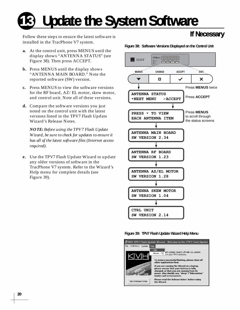
Figure 38: Software Versions Displayed on the Control Unit
Figure 39: TPV7 Flash Update Wizard Help Menu
Update the System SoftwareIf Necessary
Follow these steps to ensure the latest software isinstalled in the TracPhone V7 system.
a. At the control unit, press MENUS until the display shows “ANTENNA STATUS” (see Figure 38). Then press ACCEPT.
b. Press MENUS until the display shows “ANTENNA MAIN BOARD.” Note the reported software (SW) version.
c. Press MENUS to view the software versions for the RF board, AZ/EL motor, skew motor, and control unit. Note all of these versions.
d. Compare the software versions you just noted on the control unit with the latest versions listed in the TPV7 Flash Update Wizard’s Release Notes.
NOTE: Before using the TPV7 Flash Update Wizard, be sure to check for updates to ensure it has all of the latest software files (Internet access required).
e. Use the TPV7 Flash Update Wizard to update any older versions of software in the TracPhone V7 system. Refer to the Wizard’s Help menu for complete details (see Figure 39).
13
0

21
Hazard Zone
080
015
Figure 40: Example of an RF Radiation Hazard Zone
Antenna
000
180
090270
135225
315 Forward
015
080
RF RadiationHazard Zone(Example)
BeginningAzimuth
EndingAzimuth
Figure 41: Azimuths Relative to Antenna’s Forward Arrow
ZONE 1= 015-080 CHANGE ACCEPT
Step 1:Set Zone 1Azimuth Range
ZONE 2= 999-999 NEXT ITEM CHANGE
Step 2:Set Zone 2Azimuth Range
XMT IN ZONES= NO NEXT ITEM CHANGE
Step 3:Set to “NO”
Figure 42: Setup Process for RF Hazard Zones
Set Up RF Hazard ZonesOptional
To prevent exposure to RF energy, which may beharmful to people who stand within 36 feet (11 meters) of the antenna, you can configure up to two RF radiation hazard zones for areas where crew and/or passengers frequent (see Figure 40). The system will disable the transmitter whenever the antenna is pointing within one of these zones.
Follow these steps to set up an RF hazard zone.
a. Determine the necessary azimuth range for the RF hazard zone(s). You will need to enter, in clockwise order, beginning and ending azimuths (>4° apart) relative to the antenna’s forward arrow, which should be pointing toward the bow (see Figure 41).
b. At the control unit, press MENUS until the display shows “CONFIGURATION.” Then press ACCEPT.
c. Press MENUS until the display shows “SET HAZARD ZONE.”
d. Press CHANGE until the display shows “SET HAZARD ZONE = YES.” Then press ACCEPT.
e. At “ZONE 1,” press CHANGE. A cursor appears under the first number in the azimuth range for RF hazard zone #1.
f. Press CHANGE until the number is set to the first digit of the beginning azimuth for the first hazard zone. Enter a zero if the azimuth value is less than 100°.
g. Press ACCEPT. The cursor moves to the next number.
h. Repeat steps f and g to set the remaining digits of the desired RF radiation hazard zone. Then press ACCEPT.
i. At “Zone 2,” repeat steps e-h to set the range for the second RF hazard zone, if desired.
j. At “XMT IN ZONES,” verify that the display shows “XMT IN ZONES = NO.” Then press MENUS.
k. Press EXIT to exit the menu.
NOTE: For more details, refer to the Configuration section of the User’s Guide.
14

2
Figure 43: Good Service Connection Indicated on Control Unit LCD
ONLINETRACKING 22.0W
NOTE: Satellites will vary depending on your location.
POWER
RUN
WAN
LAN
VOIP
PHONE 2
PHONE 1
POWER
RUN
WAN
LAN
VOIP
PHONE 2
PHONE 1
Figure 44: MTA Status Lights
Figure 45: Welcome Page for Testing
Test the System
Now that you have installed the system, you can test the system to verify it is ready for customer delivery. Follow these steps to test the system for proper operation.a. Ensure the antenna has a clear, unobstructed view of the sky.
b. With the TracPhone system powered on, restart the networked computer(s).
c. Verify that the antenna is tracking the service satellite and the modem is connected to the mini-VSAT Broadband service, as indicated by the control unit screen shown in Figure 43. If an error appears, refer to the Troubleshooting section of the User’s Guide.
d. If the customer has activated the TracPhone system for mini-VSAT Broadband service, verify that the system can access the Internet by entering any common website address (URL) into the browser.
e. If the customer has activated the TracPhone system, also verify that you can place a voice call. First make sure the MTA’s “VOIP” light is lit green (see Figure 44). Then, using any telephone connected to the MTA, place a call to someone on a terrestrial or cellular network and ask that person to call you back at the customer’s number.
f. Even if the customer has not yet activated the TracPhone system for mini-VSAT Broadband service, you can still check the modem’s communications to the land-based hub. Open the web browser on any networked computer and enter the following address to access the Welcome page: http://208.83.165.11/mbbtest. Verify that the Welcome page appears in the browser (see Figure 45).
Once the system is online, do not turn it off for 30 minutes to allow the modem to download the latest configuration files via the satellite. If the modem is unable to connect, you may upload the files manually via the modem’s web interface. Details are available to technicians on the KVH Partner Portal.
IMPORTANT!
15
2
23
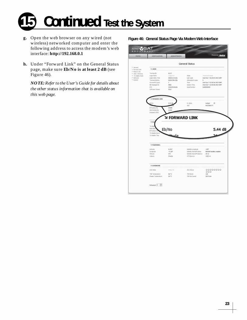
Figure 46: General Status Page Via Modem Web Interface
Continued Test the System
g. Open the web browser on any wired (notwireless) networked computer and enter the following address to access the modem’s web interface: http://192.168.0.1
h. Under “Forward Link” on the General Status page, make sure Eb/No is at least 2 dB (see Figure 46).
NOTE: Refer to the User’s Guide for details about the other status information that is available on this web page.
15

2
Figure 47: Customer Welcome Kit
RadiationHazard
RadiationHazard
36 ft (11 m)36 ft (11 m)
80
5
80
5Antenna
Figure 48: Safe Distance to Avoid Risk of RF Radiation Exposure
Figure 49: Example of Satellite Blockage
Educate the Customer
The installation is complete! Before you leave the vessel, enter the system serial numbers on the first page of the User’s Guide, give the Welcome Kit to the customer, and review the following with the customer:• Advertised data speeds and reasons why speeds may decrease at times (refer toSection 15 of the End User Agreement)
• Voice service and all associated long-distance charges (refer to the Airtime Rate Sheet)
• Fair Access Policy: streaming video and peer-to-peer file sharing are prohibited (refer to Sections 44-45 of the End User Agreement)
Also explain how to use the system and be sure the customer understands the following:
• The antenna transmits RF energy that is potentially harmful. Whenever the system is powered on, make sure everyone stays more than 36 feet (11 meters) away from the antenna within its 5-80° look angle (see Figure 48). No hazard exists directly above the antenna and anywhere below the antenna’s mounting plane.
• Keep the radome installed on the antenna at all times. The radome protects the antenna’s moving parts from wind, rain, and debris.
• The antenna must have a clear view of the sky to communicate via satellite. Common causes of blockage include masts, trees, buildings, and bridges (see Figure 49).
• Clean the antenna regularly. Dirt buildup on the radome can affect communications. Heavy rain or snow may also temporarily interrupt communications.
• The vessel must be located within the coverage area of the satellite. To view a coverage map, visit www.kvh.com/minivsatmap.
• The system must be activated for mini-VSAT Broadband service. For activation details, refer to the Activation Checklist located in the Welcome Kit or on the web at www.kvh.com/mvbservice.
16
4

Appendices
25
This section provides a system wiring diagram and supplemental instructions for terminating an LMR-400-75 cable.
Contents
A. Wiring Diagram................................... 27
B. Terminating LMR-400-75 Cable ........ 28

Wiring Diagram
A27
SerialGP10
Power
Power Not Used
J1AC PWR
J3Rx RF
J2Tx RF
J4ACU
J5CONSOLE
J6BUC PWR J8
USERENET
J7ACUENET
NO OPERATORSERVICEABLEPARTS INSIDE,DO NOT OPEN
CAUTION
MODEL: VMBR-1510 ArcLightPART: 1234567 REV XXXSERIAL: XX-XXXXXXCAGE CODE: 12345
Antenna On/Off AudioSIM
Power
Power
Power
Power
4 3 2 18 7 6 5
POE 48V
+
12V DC RSTR WAN LAN PHONE 2 PHONE 1
1 2 11109876 12543
Data
Power
Antenna
Control Unit
MTx
MRx
Modem
Service Module
Blue/White
White/Blue
Brown/White
White/Gray
Gray/White
White/Orange
Orange/White
White/Brown
Red
Black
Terminal Strip Connector
Note: Terminals #3and #8 are not used
LaptopPC
AnalogPhone
MTA
Switch
Appendix

2
Figure 50: Cutting the Cable
Figure 51: Reshaping the Cable
Figure 52: Placing the Heat Shrink Tubing and Ferrule
Figure 53: Stripping the End to Expose the Center Conductor
Terminating LMR-400-75 CableAppendix
These instructions explain how to terminate anLMR-400-75 RF cable with an EZ-400-FMH-75 “F” connector using the tools from the TK-400EZ-75 tool kit. For more detailed instructions, refer to the Times Microwave website (www.timesmicrowave.com).
1. Using the CCT-01 cutting tool, cut the cable evenly (see Figure 50).
2. Since cutting the cable can deform the end, gently round the end of the cable using a pair of needle-nose pliers (see Figure 51). Also make sure the center conductor is centered within the cable.
3. Place the heat shrink sleeve and metal ferrule onto the cable (see Figure 52).
4. Insert the end of the cable into the #1 end of the ST-400EZ stripping tool (see Figure 53). Then rotate the tool clockwise around the cable until the tool turns easily. The end of the cable should now be stripped to expose the center conductor.
B
8

Figure 54: Removing Plastic Residue
Figure 55: Stripping the Cable Jacket
Figure 56: Cable Stripped, Exposing Dielectric
Figure 57: Deburring the Center Conductor
Continued Terminating LMR-400-75 Cable
5. Using a utility knife, carefully remove anyresidual plastic from the center conductor, if necessary (see Figure 54).
6. Insert the end of the cable into the #2 end of the ST-400EZ stripping tool (see Figure 55). Then rotate the tool clockwise around the cable until the tool turns easily. This removes the cable jacket from the end of the cable, exposing the braid and dielectric (see Figure 56).
7. Using the DBT-02 tool, deburr and chamfer the center conductor (see Figure 57). Avoid nicking the aluminum tape covering the dielectric.
B
29

3
Figure 58: Flaring the Braid
Figure 59: Pushing On the Connector
Figure 60: Trimming the Braid
Figure 61: Sliding the Ferrule Over the Braid
Continued Terminating LMR-400-75 Cable
8. Gently flare the braid with your fingers (seeFigure 58).
9. Insert the end of the cable into the connector body until the dielectric is firmly seated inside the connector (see Figure 59). Be sure all braid wires remain on the outside of the connector.
10. Trim any excess braid (see Figure 60), if necessary. The braid should assemble flush to within 1/16" (1.6 mm) of the connector shoulder.
11. Slide the ferrule over the braid until it is flush against the connector shoulder (see Figure 61).
B
0

Figure 62: Crimping the Ferrule onto the Cable
Figure 63: Applying the Heat Shrink Tubing
Continued Terminating LMR-400-75 Cable
12. Using an appropriate crimp tool (either theCT-400/300 or the HX-4 with Y1719 dies), crimp the ferrule in place (see Figure 62). Crimp as close to the connector body as possible.
13. Crimp the ferrule again, but further back from the connector. However, be careful not to crimp the cable jacket.
14. Slide the heat shrink sleeve over the connector body and heat it to compress it into place (see Figure 63). When you are done, the heat shrink should extend from the rear of the connector to the cable jacket. This forms a weather-tight seal.
15. Using a multimeter or similar device, check the continuity of the cable.
B
31

www.kvh.com
KVH Industries, Inc. Middletown, RI U.S.A. Tel: +1 401 847 3327 Fax: +1 401 849 0045E-mail: [email protected]
KVH Europe A/S Kokkedal, Denmark Tel: +45 45 160 180 Fax: +45 45 160 181E-mail: [email protected]
KVH Norway AS Horten, Norway
Tel: +47 33 03 05 30 Fax: +47 33 03 05 31
E-mail: [email protected]
KVH Singapore Singapore
Tel: +65 6829 2343Fax: +65 6829 2121
E-mail: [email protected]