TRAC-A-RAC MANUAL 100 - columbiamachine.comcolumbiamachine.com/docs/knowledge-base/Trac-A-Rac...
117
Knowledge Base Article Type: Instructions TRAC-A-RAC Set-up / Configuration Procedure & Installation WARNING Never work on, clean or service this unit, control panel or any machine or open or remove any protective cover, guard, grate, door, or maintenance panel until the power or energy sources has been turned off, locked out / tagged out, and all moving parts have come to a complete stop and or blocked to prevent movement. Machinery is dangerous – avoid personal injury and or death by following manufacture, Local, and OHSA safety procedures. Contact Columbia Machine for safety decals, guards, horns and beacons. Description: Instructions on “How to” set-up / configuration procedure and installation on Trac-A-Rac’s using Allen Bradley PLC, Radio Modem (Control Chief), RMC-Delta Module. This document is intended for Service Representatives and Engineers.
Transcript of TRAC-A-RAC MANUAL 100 - columbiamachine.comcolumbiamachine.com/docs/knowledge-base/Trac-A-Rac...
Knowledge Base
Article Type: Instructions
TRAC-A-RAC
Set-up / Configuration Procedure
& Installation
WARNING Never work on, clean or service this unit, control panel or any machine or open or remove any protective cover, guard, grate, door, or maintenance panel until the power or energy sources has been turned off, locked out / tagged out, and all moving parts have come to a complete stop and or blocked to prevent movement. Machinery is dangerous – avoid personal injury and or death by following manufacture, Local, and OHSA safety procedures. Contact Columbia Machine for safety decals, guards, horns and beacons.
Description:
Instructions on “How to” set-up / configuration procedure and installation
on Trac-A-Rac’s using Allen Bradley PLC, Radio Modem (Control Chief),
RMC-Delta Module. This document is intended for Service Representatives
and Engineers.

Page 1 of 116
TRAC-A-RAC
SET-UP/CONFIGURATION PROCEDURE & INSTALLATION
Ver1.1
Page 2 of 116
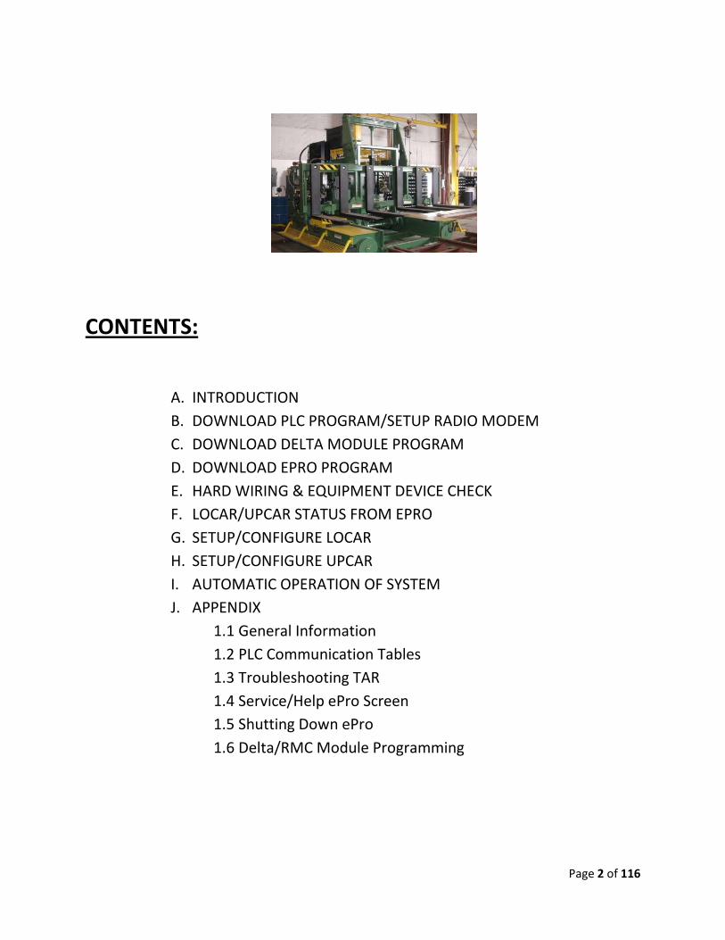
CONTENTS:
A. INTRODUCTION
B. DOWNLOAD PLC PROGRAM/SETUP RADIO MODEM
C. DOWNLOAD DELTA MODULE PROGRAM
D. DOWNLOAD EPRO PROGRAM
E. HARD WIRING & EQUIPMENT DEVICE CHECK
F. LOCAR/UPCAR STATUS FROM EPRO
G. SETUP/CONFIGURE LOCAR
H. SETUP/CONFIGURE UPCAR
I. AUTOMATIC OPERATION OF SYSTEM
J. APPENDIX
1.1 General Information
1.2 PLC Communication Tables
1.3 Troubleshooting TAR
1.4 Service/Help ePro Screen
1.5 Shutting Down ePro
1.6 Delta/RMC Module Programming

Page 3 of 116
A. INTRODUCTION :
OPERATIONAL SETUP & SYSTEM CALIBRATION:
Before the Cars can be operated in automatic mode, the following tables MUST be completed for each car. (Refer to the Locar and Upcar installation guide section in this manual.)
LOCAR:
• DOWNLOAD LOCAR PLC PROGRAM
• DOWNLOAD EPRO OPERATOR INTERFACE PROGRAM
• DOWNLOAD DELTA MODULE PROGRAM
• LOCAR ENCODER – VERIFY OPERATION, COUNT, DIRECTION
• LOCAR VELOCITY (SPEED) SETTING
• LOCAR ACCELERATION & DECELERATION (RAMP) SETTING
• LOCAR COUNT TABLE: LOAD & UNLOAD POSITION TABLE
• LOCAR COUNTS TABLE: FROM ORIGIN TO KILNS
• LOCAR CREEP COUNTS TABLE: FROM ORIGIN TO LOAD KILN
• LOCAR CREEP COUNTS TABLE: FROM LK TO UK (UK > LK) FORWARD
• LOCAR CREEP COUNTS TABLE: FROM LK TO UK (UK < LK) REVERSE
• LOCAR CREEP COUNTS TABLE: FROM UNLOAD KILN TO UNLOAD POS.
• ALARM TABLE FOR UPCAR AT LOAD KILN
• ALARM TABLE FOR UPCAR AT UNLOAD KILN
UPCAR:
• DOWNLOAD LOCAR PLC PROGRAM
• DOWNLOAD DELTA MODULE PROGRAM
• UPCAR ENCODER – VERIFY OPERATION, COUNT, DIRECTION
• UPCAR VELOCITY (SPEED) SETTING
• UPCAR ACCELERATION & DECELERATION (RAMP) SETTING
• UPCAR COUNTS TABLE: LOAD POS.
• UPCAR COUNTS TABLE: UNLOAD
• UPCAR COUNTS TABLE: LOAD KILN COUNTS
• UPCAR COUNTS TABLE: UNLOAD KILN COUNTS
• UPCAR COUNTS TABLE: GOING INTO LOAD KILN CREEP COUNTS
• UPCAR COUNTS TABLE: GOING OUT OF LOAD KILN CREEP COUNTS
• UPCAR COUNTS TABLE: GOING INTO UNLOAD KILN CREEP COUNTS
• UPCAR COUNTS TABLE: GOING OUT OF UNLOAD KILN CREEP COUNTS
Page 4 of 116
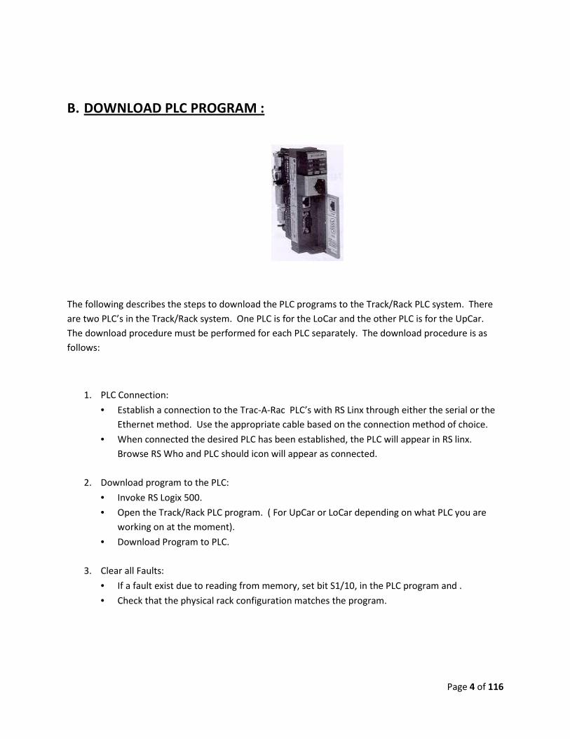
B. DOWNLOAD PLC PROGRAM :
The following describes the steps to download the PLC programs to the Track/Rack PLC system. There
are two PLC’s in the Track/Rack system. One PLC is for the LoCar and the other PLC is for the UpCar.
The download procedure must be performed for each PLC separately. The download procedure is as
follows:
1. PLC Connection:
• Establish a connection to the Trac-A-Rac PLC’s with RS Linx through either the serial or the
Ethernet method. Use the appropriate cable based on the connection method of choice.
• When connected the desired PLC has been established, the PLC will appear in RS linx.
Browse RS Who and PLC should icon will appear as connected.
2. Download program to the PLC:
• Invoke RS Logix 500.
• Open the Track/Rack PLC program. ( For UpCar or LoCar depending on what PLC you are
working on at the moment).
• Download Program to PLC.
3. Clear all Faults:
• If a fault exist due to reading from memory, set bit S1/10, in the PLC program and .
• Check that the physical rack configuration matches the program.

Page 5 of 116
4. Set up Radio Modem:
• Make sure there are no RED LED Fault lights.
Indicator LED Definition and Function
Indicator Definition Function
LINK Link Status Indicates an established communication link between modules. The RD indicator should also be flashing to show valid data is being processed
TD Transmit Data
The Transmit Data LED indicates when the module is sending data.
RD Received Data
The Receive Data LED flashes ON to indicate when a VALID packet has been processed.
FAULT Fault The Fault LED provides an indication of module error conditions.
Configure DIP switch settings on Modem card as per drawing.
LED INDICATORS
LoCar UpCar

Page 6 of 116
5. Write PLC program to EEPROM:
• From the Main Menu click on save to EEPROM.
6. Verify all I/O in the System:
• Ring out all inputs.
• Ring out all outputs.
• Verify all analog signals.

Page 7 of 116
C. DOWNLOAD RMC-DELTA MODULE PROGRAM:
The following steps describe what is required to setup the Delta Module:
1. Check and verify all wiring and connections to the Delta Module.
• Verify wiring from Delta module to Encoder:
• Verify wiring from Delta module to Valve controller:
2. Verify Power to the Delta Module.
• Verify power wires to the Delta Module.
• Power to the Delta Module should be 24VDC.

Page 8 of 116
See Delta Module/Encoder
Wiring Schematic in drawing
package to verify wiring.

Page 9 of 116
3. Install RMC Tools Software on to your computer.
• Install RMC Tools Software Version 3.37.0 the latest version.
Installation
You can install RMCTools from the CD that shipped with the RMC, or by downloading it from
Delta’s download page at www.deltamotion.com/dloads/.
To install from the CD:
a) Insert the CD and wait for the splash screen to appear. Click Install RMCTools. Follow the
instructions for installation. If the splash screen does not automatically open, run the
autorun.exe file.
To install by downloading:
a) Go to Delta’s download website at http://www.deltamotion.com/dloads/
b) Locate the RMCTools download under RMC70 Series Software and save it to your computer.
c) Run rmctoolsinstall.exe and follow the instructions.
RMCTOOLS
VERSION
Page 10 of 116
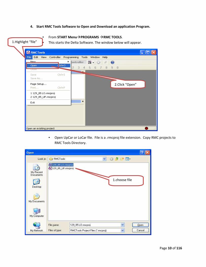
4. Start RMC Tools Software to Open and Download an application Program.
• From START Menu�PROGRAMS �RMC TOOLS.
• This starts the Delta Software. The window below will appear.
• Open UpCar or LoCar file. File is a .rmcproj file extension. Copy RMC projects to
RMC Tools Directory.
1.Highlight “file”
2.Click “Open”
1.choose file

Page 11 of 116
• The following window will appear.
• Connect to the Delta Module. �Connection Path
• Connection Path screen will appear. Choose USB and make sure the USB cable that
was provided is connected between the Delta Module and the computer.
1.Highlight
“Controller”
2.Click “Connection
Path”
1.choose USB.
2.Click “OK”.

Page 12 of 116
• Once Connection to the Delta module has been established. Download the LoCar or
UpCar program to the module.
Download All to Controller
After the down load ensure that
there are NO FAULTS on the
Module. RED LED indicates a
FAULT.
1.Highlight
“Controller”
2.Click “Download All to
Controller”
Page 13 of 116
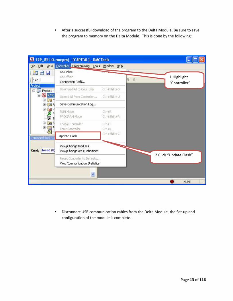
• After a successful download of the program to the Delta Module, Be sure to save
the program to memory on the Delta Module. This is done by the following:
• Disconnect USB communication cables from the Delta Module, the Set-up and
configuration of the module is complete.
Update Flash
1.Highlight
“Controller”
2.Click “Update Flash”

Page 14 of 116
D. DOWNLOAD EPRO PROGRAM:
1. Computer configuration:
Reconfigure your laptop computer to communicate with the ePro unit. The IP address of
your computer should be set to a specific IP address different from the IP address of the
ePro unit, and the computer must be configured to NOT automatically obtain an IP
address. The set-up configuration is as follows:
� From Start Menu of the computer, browse to settings and select “Network Connections”
� Start ���� Settings ���� Control Panel ���� Network Connections
• Right click on Local Area Connection and select “Properties”.
Right click on Local Area
Connection

Page 15 of 116
• Select “Properties”.
Click Properties
1. Highlight “Internet
Protocol (TCP.IP)”
3. Click on “Properties”
2. Check the boxes
Page 16 of 116
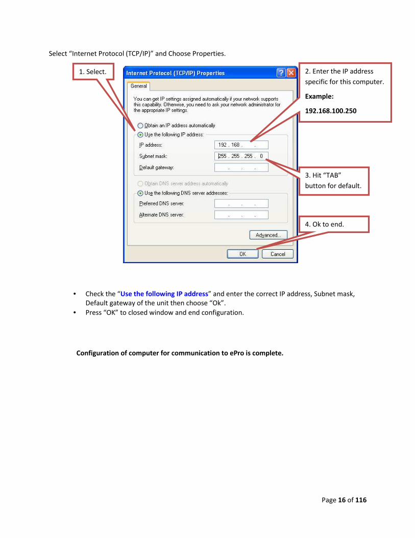
Select “Internet Protocol (TCP/IP)” and Choose Properties.
• Check the “Use the following IP address” and enter the correct IP address, Subnet mask,
Default gateway of the unit then choose “Ok”.
• Press “OK” to closed window and end configuration.
Configuration of computer for communication to ePro is complete.
2. Enter the IP address
specific for this computer.
Example:
192.168.100.250
4. Ok to end.
3. Hit “TAB”
button for default.
1. Select.
Page 17 of 116
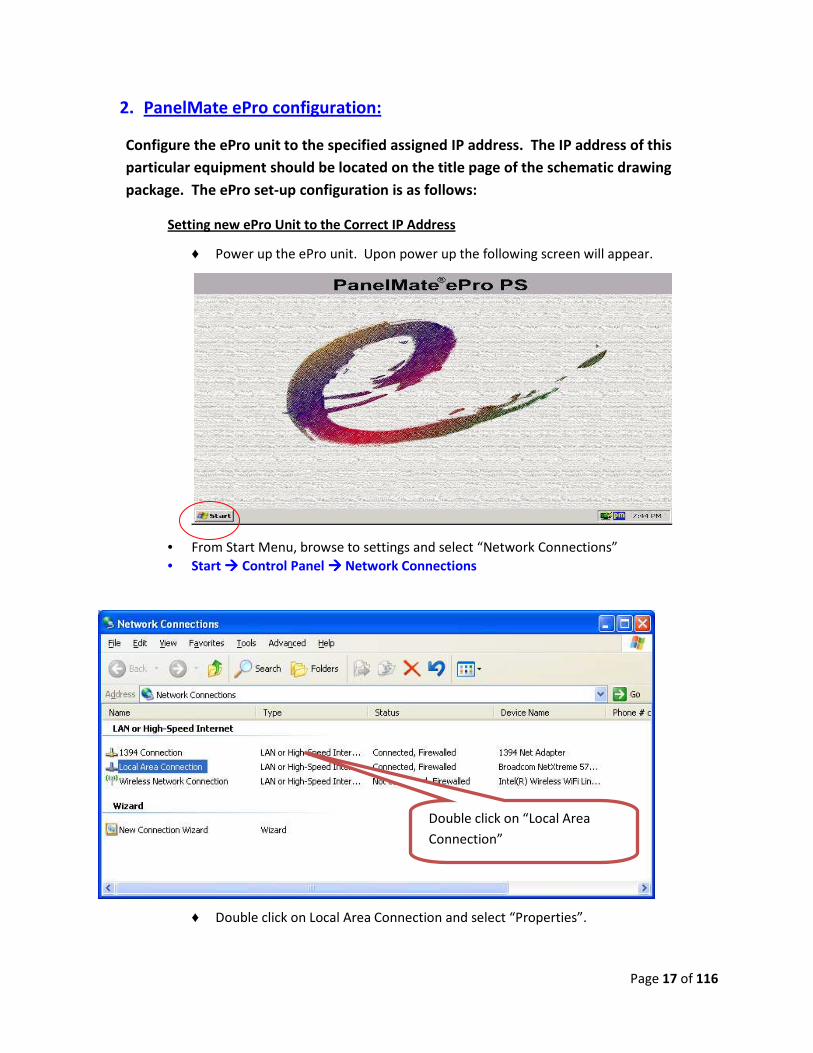
2. PanelMate ePro configuration:
Configure the ePro unit to the specified assigned IP address. The IP address of this
particular equipment should be located on the title page of the schematic drawing
package. The ePro set-up configuration is as follows:
Setting new ePro Unit to the Correct IP Address
♦ Power up the ePro unit. Upon power up the following screen will appear.
• From Start Menu, browse to settings and select “Network Connections”
• Start ���� Control Panel ���� Network Connections
♦ Double click on Local Area Connection and select “Properties”.
Double click on “Local Area
Connection”

Page 18 of 116
♦ Select “Properties”.
• Select “Internet Protocol (TCP/IP)” and Choose Properties.
Click Properties
1. Highlight “Internet
Protocol(TCP.IP)”
3. Click on “Properties”
2. Check the boxes
Page 19 of 116
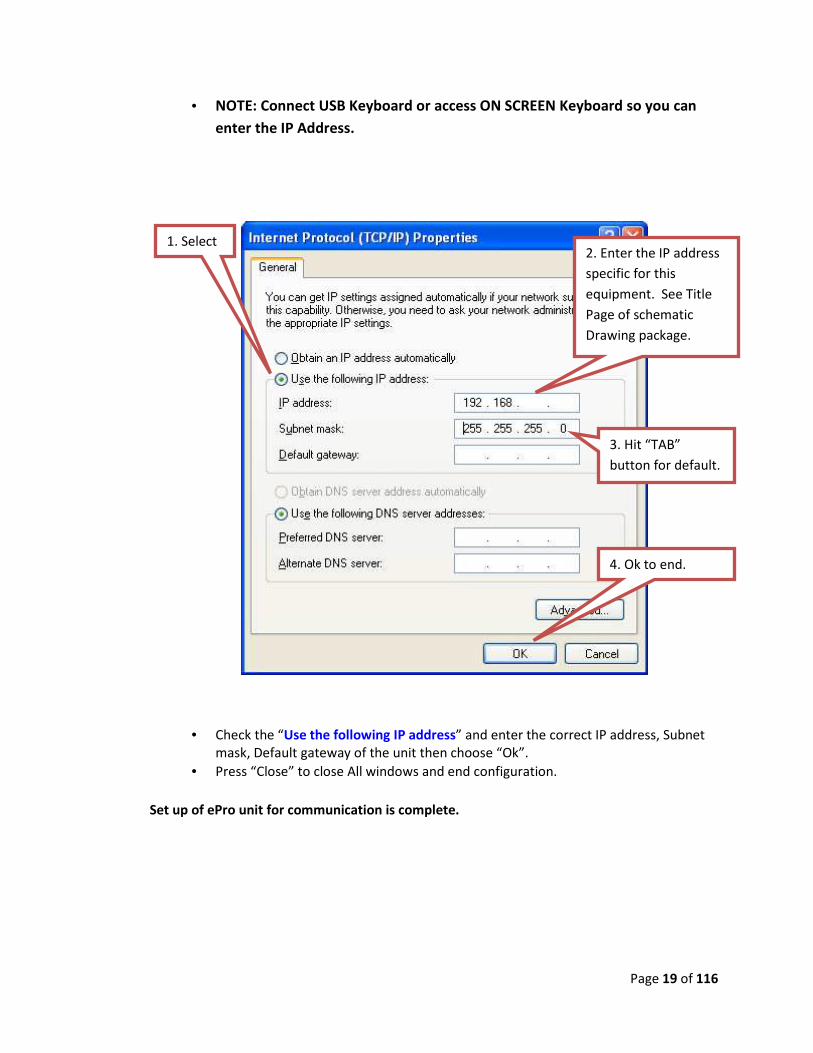
• NOTE: Connect USB Keyboard or access ON SCREEN Keyboard so you can
enter the IP Address.
• Check the “Use the following IP address” and enter the correct IP address, Subnet
mask, Default gateway of the unit then choose “Ok”.
• Press “Close” to close All windows and end configuration.
Set up of ePro unit for communication is complete.
2. Enter the IP address
specific for this
equipment. See Title
Page of schematic
Drawing package.
4. Ok to end.
3. Hit “TAB”
button for default.
1. Select

Page 20 of 116
� Typical Colmac ePro PanelMate Ethernet Standard Sheet
Ethernet Communication
Type of Equipment AB SLC 5/05 ePro w/ Ethernet
BM / CPM 192.168.100.102 192.168.100.112
MBS 192.168.100.103 192.168.100.113
Curing Controls 192.168.100.104 192.168.100.114
Pallet Handling Main (UL / PTS / RTS) 192.168.100.105 192.168.100.115
TAR / PTS / RTS Locar (Hydraulic system) 192.168.100.106 192.168.100.116
TAR / RTS / PTS Upcar (Elec. System) 192.168.100.108 192.168.100.118
QBR 192.168.100.107 192.168.100.117
Splitter (if connected on network) 192.168.100.121 192.168.100.122
Clamp Turnover 192.168.100.125 n/a
Pre-PatternMaker 192.168.100.109 192.168.100.119
CommandView Computer 192.168.100.101
Laptop Computer # 1 192.168.100.91
Laptop Computer # 2 192.168.100.92
� Subnet mask: 255.255.255.0
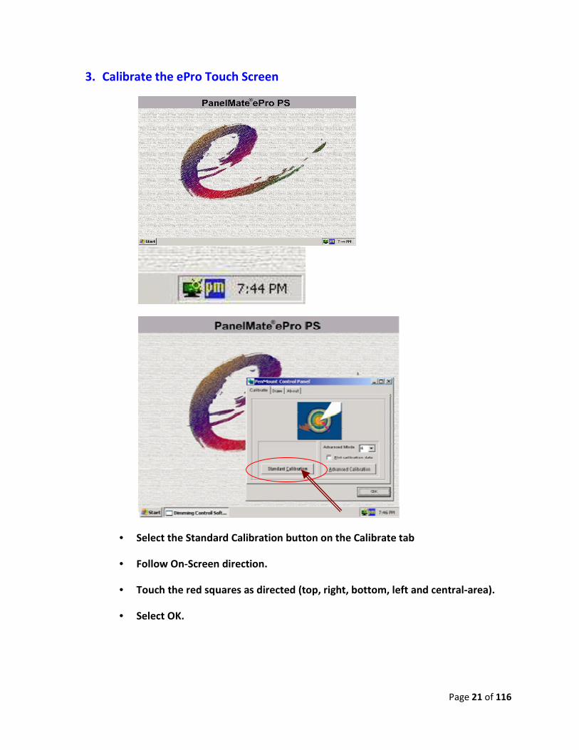
3. Calibrate the ePro Touch Screen
• Select the Standard Calibration button on the
• Follow On-Screen direction.
• Touch the red squares as directed (top, right, bottom, left and central
• Select OK.
Calibrate the ePro Touch Screen
Select the Standard Calibration button on the Calibrate tab
Screen direction.
Touch the red squares as directed (top, right, bottom, left and central
Page 21 of 116
Touch the red squares as directed (top, right, bottom, left and central-area).
Page 22 of 116
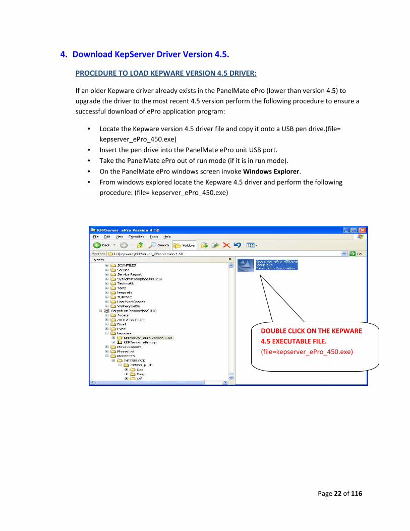
4. Download KepServer Driver Version 4.5.
PROCEDURE TO LOAD KEPWARE VERSION 4.5 DRIVER:
If an older Kepware driver already exists in the PanelMate ePro (lower than version 4.5) to
upgrade the driver to the most recent 4.5 version perform the following procedure to ensure a
successful download of ePro application program:
• Locate the Kepware version 4.5 driver file and copy it onto a USB pen drive.(file=
kepserver_ePro_450.exe)
• Insert the pen drive into the PanelMate ePro unit USB port.
• Take the PanelMate ePro out of run mode (if it is in run mode).
• On the PanelMate ePro windows screen invoke Windows Explorer.
• From windows explored locate the Kepware 4.5 driver and perform the following
procedure: (file= kepserver_ePro_450.exe)
DOUBLE CLICK ON THE KEPWARE
4.5 EXECUTABLE FILE.
(file=kepserver_ePro_450.exe)

Page 23 of 116
THIS SCREEN WILL
APPEAR NEXT.
SELECT “MODIFY” THEN
HIT THE “NEXT” BUTTON
TO CONTINUE.
Page 24 of 116
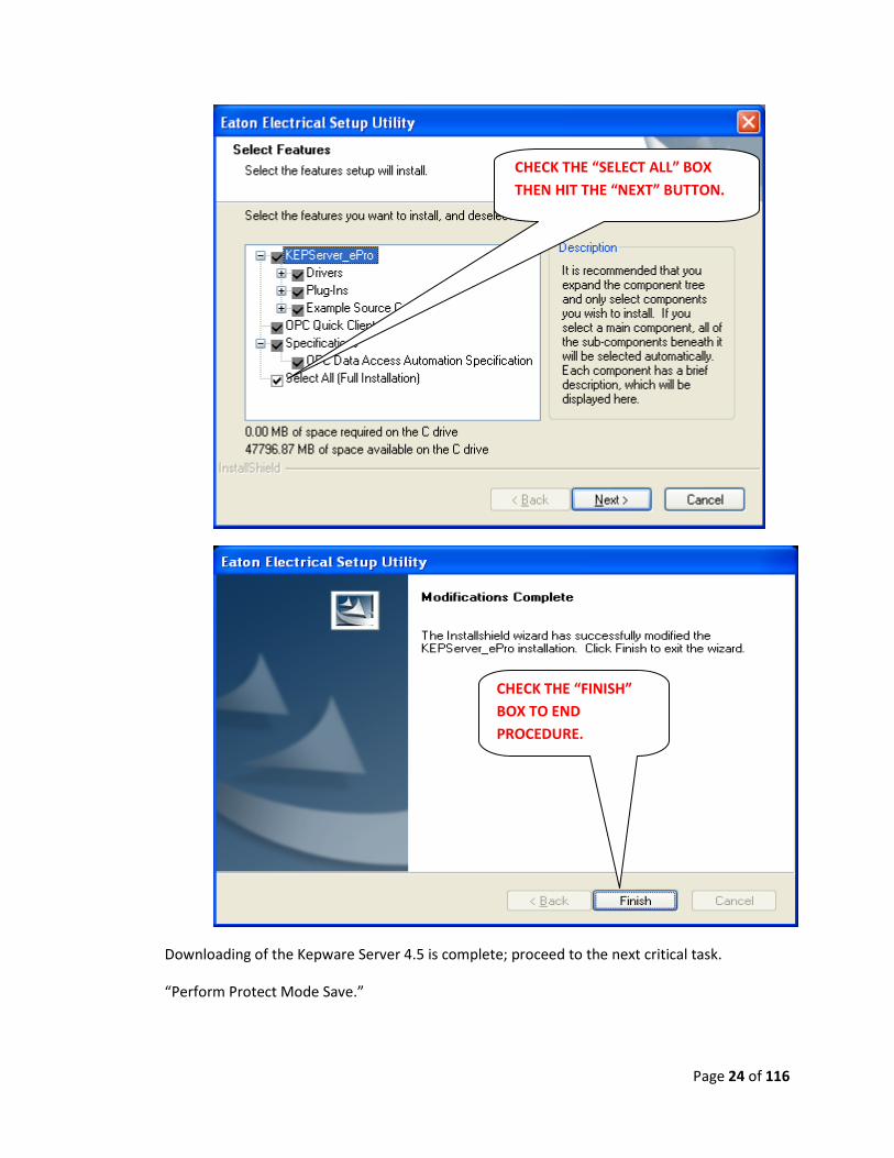
Downloading of the Kepware Server 4.5 is complete; proceed to the next critical task.
“Perform Protect Mode Save.”
CHECK THE “SELECT ALL” BOX
THEN HIT THE “NEXT” BUTTON.
CHECK THE “FINISH”
BOX TO END
PROCEDURE.
Page 25 of 116
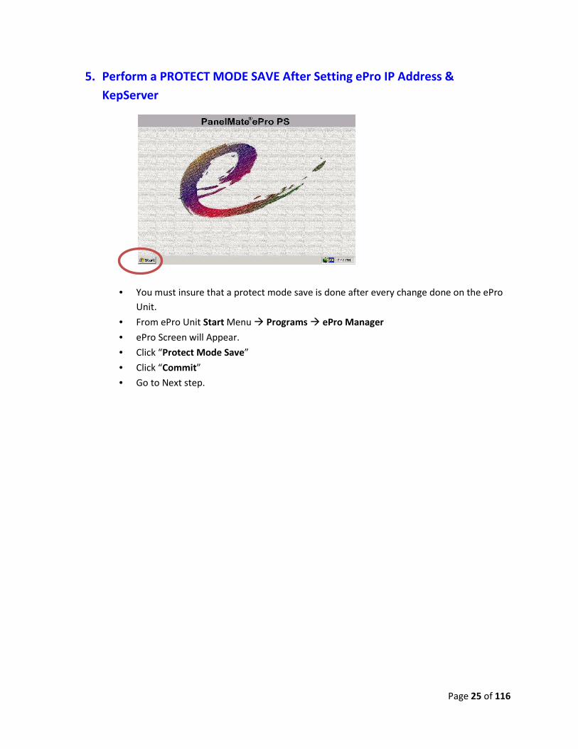
5. Perform a PROTECT MODE SAVE After Setting ePro IP Address &
KepServer
• You must insure that a protect mode save is done after every change done on the ePro
Unit.
• From ePro Unit Start Menu � Programs � ePro Manager
• ePro Screen will Appear.
• Click “Protect Mode Save”
• Click “Commit”
• Go to Next step.
Page 26 of 116
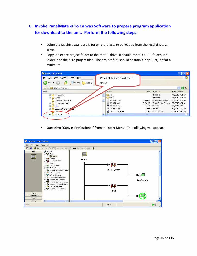
6. Invoke PanelMate ePro Canvas Software to prepare program application
for download to the unit. Perform the following steps:
• Columbia Machine Standard is for ePro projects to be loaded from the local drive, C:
drive.
• Copy the entire project folder to the root C: drive. It should contain a JPG folder, PDF
folder, and the ePro project files. The project files should contain a .chp, .ucf, .opf at a
minimum.
• Start ePro “Canvas Professional” from the start Menu. The following will appear.
Project file copied to C:
drive.

Page 27 of 116
� Open the project file. File is a .chp
• Select Project file and Open.
1. Select .chp File
2. Open
1. Highlight “file”
2. Select “Open”
Page 28 of 116
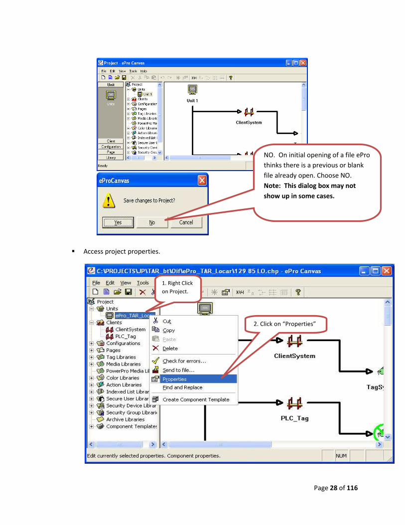
� Access project properties.
1. Right Click
on Project.
2. Click on “Properties”
NO. On initial opening of a file ePro
thinks there is a previous or blank
file already open. Choose NO.
Note: This dialog box may not
show up in some cases.

Page 29 of 116
• From properties, enter all the settings below:
Note: For Step 8, IP Address, See Colmac ePro PanelMate Ethernet Standard Sheet
(reference page 8) for the correct IP address of the machine.
1. Select Destination
2. Select Single Row
4. Select
Configuration
Runtime ucf file
5. Select ePro PS for
X86
6. Select KepServer ePro for X86
7. Select KEPServer ePro opf
file 8. Type in the IP address
9. Select Ok to close window
Transfer .ucf = Configuration
(PanelMate PowerPro)
Transfer Runtime = Executive
Firmware
(PanelMate PowerPro)
Transfer Driver = Comm.
Drivers
(PanelMate PowerPro)
3. Yes to Transfer .ucf
Yes to Transfer Runtime
Yes to Transfer Driver(s)

Page 30 of 116
• Next, download the application project to the ePro unit.
o Connect an Ethernet cable from the computer to the ePro unit. If an
Ethernet switch is not use and you are connecting directly to the ePro unit
you MUST use an Ethernet Cross-over cable. Perform the following steps to
send a file to the ePro Unit:
o Right click on project name and send to file.
• Select "Send". The system will check for errors and if the project has no error, it will be
sending to ePro unit.
• The estimate time for completion is about 2 to 5 minutes.
1. Right Click
on Project.
2. Click on “Properties”
Click “Send”

Page 31 of 116
• After sending is complete, select “Done” to exit. Only select Done when the “Done!”
message appears on the window screen.
• Next, manually copy the project JPG and PDF folders to the D drive on the ePro Unit.
Copy the JPG and PDF folders onto a Pen Drive and use Windows Explorer on the ePro
unit to transfer the files from the Pen drive to the D drive on the ePro Unit.
• Now, update the Font on the ePro Unit:
♦ From the Start Menu, browse Setting and select Control Panel
♦ Open Font folder, and select “Install New Font” from file menu.
♦ Select D drive/cfg/font/Arial Unicode MS (True Type) then choose “OK”.
♦ The Font update is complete.
Only Click On the Done
button when the “Done”
MESSAGE appears on the
screen.

Page 32 of 116
7. Execute BAT FILE:
• From ePro Start Menu � Programs � Run “Windows Explorer”
• Go to Directory� C:\Program Files\Cutler-Hammer\ePro Software Suite\System\
• From this Directory Double Click on Bat file: reg_eProPS.bat
• The bat file will automatically run.
8. Perform a PROTECT MODE SAVE:
• This is the Most CRITICAL step of the download process. You must insure that a protect
mode save is done after every change that is done on the ePro Unit.
• From ePro Start Menu � Programs � ePro Manager
• ePro Screen will Appear
• Click “Protect Mode Save”
• Click “Commit”
• ePro Unit will go Into Run Mode.
9. Check ePro functionality
� The ePro Unit should automatically RUN and Download is Complete
� Check all Screens to see that ePro is communicating with PLC.
� Procedure Completed.

Page 33 of 116
E. HARD WIRING & EQUIPMENT DEVICE CHECK:
1 Major Panels:
• UpCar PLC Panel.
• LoCar Main PLC Panel.
• LoCar Push Button Station.
• Starter Panel.
2 See Proximity switch layout drawing and check that all switches are wired and accounted
for. Also check solenoid valves. Place a check mark when each has been verified.
SWITCHES ON LOCAR:
PC-1, KILN DOOR OPEN
PX-2, RAILS ALIGNED-ON TRACK
PX-3, UPCAR ON LOCAR
PX-4, DOCKING ENGAGED
PX-5, DOCKING RELEASED
LS-2, END OF RAIL SAFETY
SOLENOID VALVES ON LOCAR:
LOCAR MANIFOLD PRESSURE RELIEF VALVE
DOCKING ENGAGE VALVE
DOCKING RELEASE VALVE
DOCKING RELIEF VALVE
Page 34 of 116
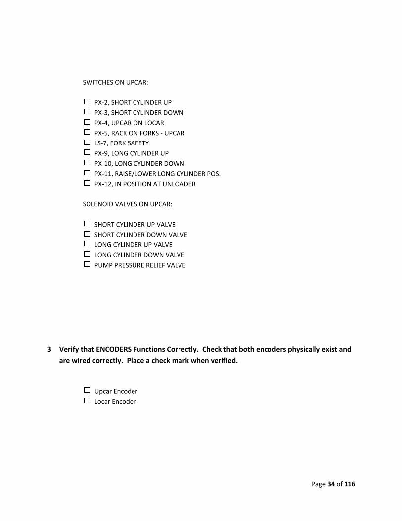
SWITCHES ON UPCAR:
PX-2, SHORT CYLINDER UP
PX-3, SHORT CYLINDER DOWN
PX-4, UPCAR ON LOCAR
PX-5, RACK ON FORKS - UPCAR
LS-7, FORK SAFETY
PX-9, LONG CYLINDER UP
PX-10, LONG CYLINDER DOWN
PX-11, RAISE/LOWER LONG CYLINDER POS.
PX-12, IN POSITION AT UNLOADER
SOLENOID VALVES ON UPCAR:
SHORT CYLINDER UP VALVE
SHORT CYLINDER DOWN VALVE
LONG CYLINDER UP VALVE
LONG CYLINDER DOWN VALVE
PUMP PRESSURE RELIEF VALVE
3 Verify that ENCODERS Functions Correctly. Check that both encoders physically exist and
are wired correctly. Place a check mark when verified.
Upcar Encoder
Locar Encoder
Page 35 of 116
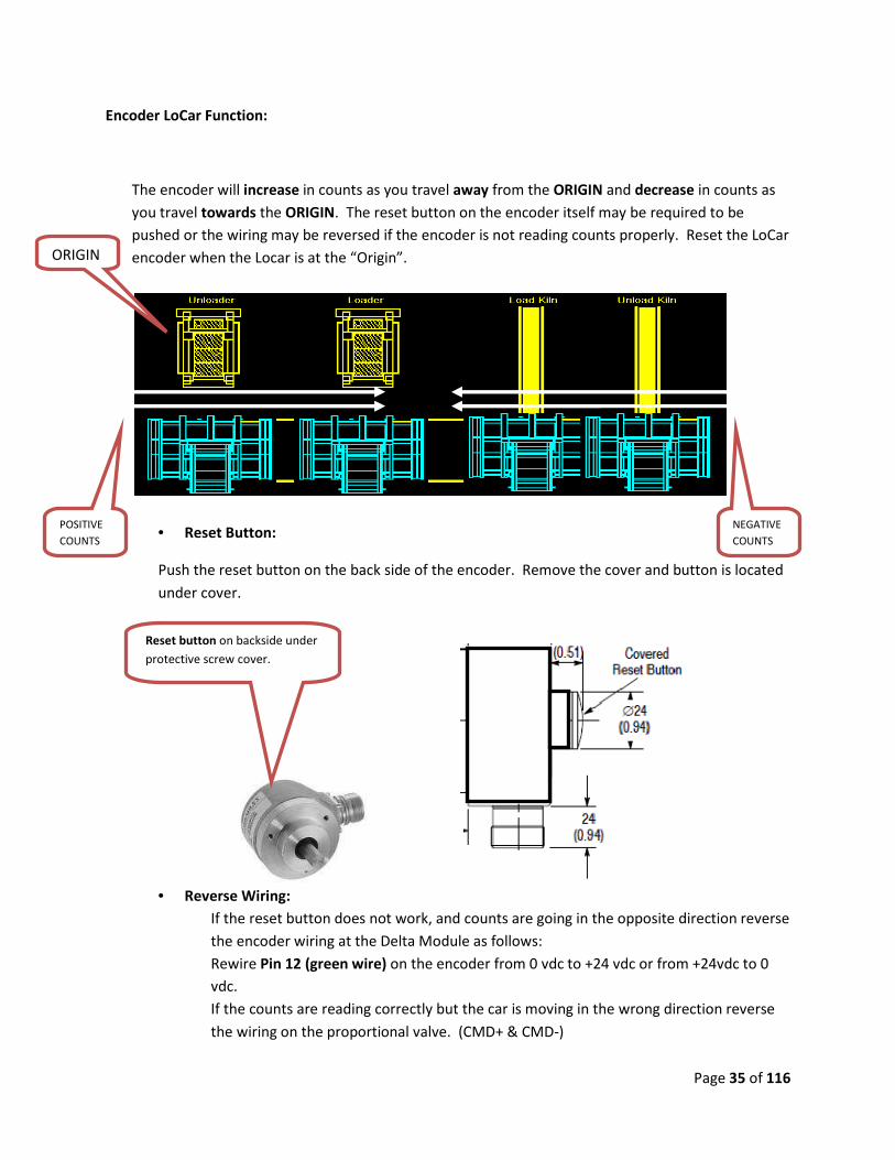
Encoder LoCar Function:
The encoder will increase in counts as you travel away from the ORIGIN and decrease in counts as
you travel towards the ORIGIN. The reset button on the encoder itself may be required to be
pushed or the wiring may be reversed if the encoder is not reading counts properly. Reset the LoCar
encoder when the Locar is at the “Origin”.
• Reset Button:
Push the reset button on the back side of the encoder. Remove the cover and button is located
under cover.
• Reverse Wiring:
If the reset button does not work, and counts are going in the opposite direction reverse
the encoder wiring at the Delta Module as follows:
Rewire Pin 12 (green wire) on the encoder from 0 vdc to +24 vdc or from +24vdc to 0
vdc.
If the counts are reading correctly but the car is moving in the wrong direction reverse
the wiring on the proportional valve. (CMD+ & CMD-)
Reset button on backside under
protective screw cover.
ORIGIN
POSITIVE
COUNTS
NEGATIVE
COUNTS

Page 36 of 116
Rewire Green
Wire to reverse
counts..
Reverse the wires to the proportional
card to get the car to run in the
opposite direction.
Page 37 of 116
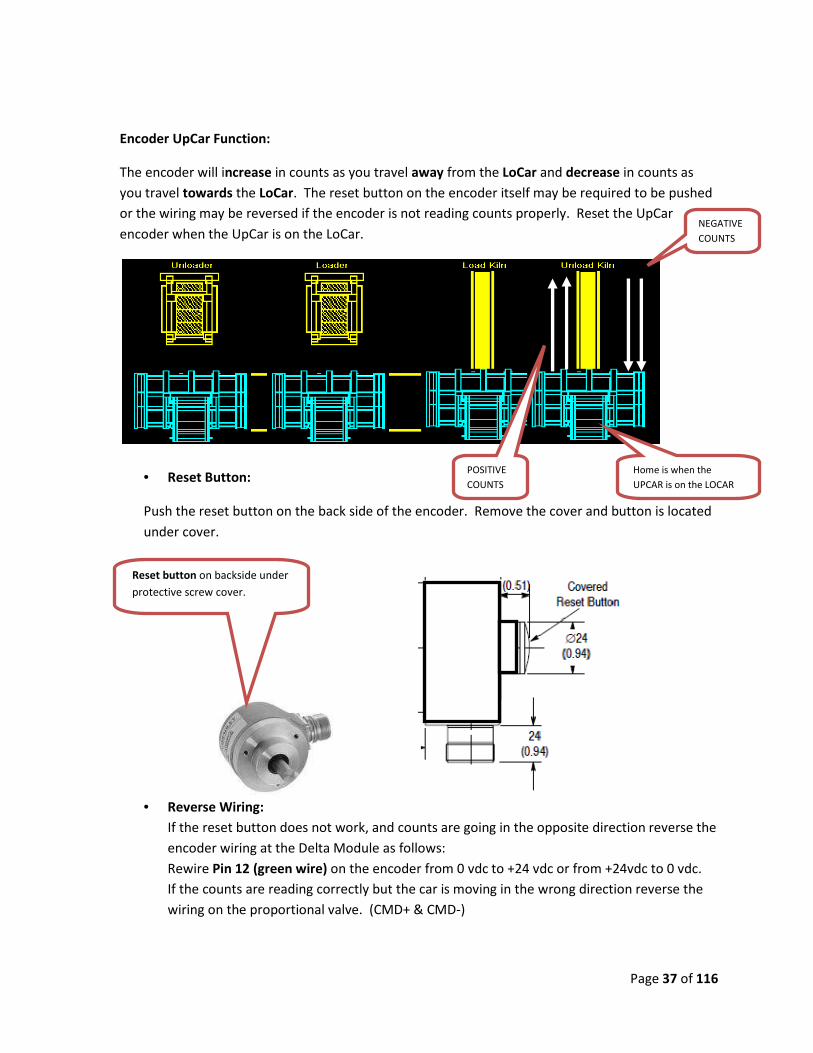
Encoder UpCar Function:
The encoder will increase in counts as you travel away from the LoCar and decrease in counts as
you travel towards the LoCar. The reset button on the encoder itself may be required to be pushed
or the wiring may be reversed if the encoder is not reading counts properly. Reset the UpCar
encoder when the UpCar is on the LoCar.
• Reset Button:
Push the reset button on the back side of the encoder. Remove the cover and button is located
under cover.
• Reverse Wiring:
If the reset button does not work, and counts are going in the opposite direction reverse the
encoder wiring at the Delta Module as follows:
Rewire Pin 12 (green wire) on the encoder from 0 vdc to +24 vdc or from +24vdc to 0 vdc.
If the counts are reading correctly but the car is moving in the wrong direction reverse the
wiring on the proportional valve. (CMD+ & CMD-)
Reset button on backside under
protective screw cover.
POSITIVE
COUNTS
NEGATIVE
COUNTS
Home is when the
UPCAR is on the LOCAR

Page 38 of 116
Rewire Green
Wire to reverse
counts..
Reverse the wires to the proportional
card to get the car to run in the
opposite direction.

Page 39 of 116
Verify that the Over Travel Limit Switch Functions and is wired correctly.
• Physically actuate the Over Travel Limit Switch and verify that the input appears on
the ePro Operator Screen.
4 Verify that the ON Track Switch Functions and is wired correctly.
• Physically actuate the ON Track Switch and verify that the input appears on the ePro
Operator Screen.
ON TRACK
Proximity SW.
Input

Page 40 of 116
5 Verify that the Kiln Safety Switch Functions and is wired correctly.
• Physically actuate the Kiln Safety Switch and verify that the input appears on the
ePro Operator Screen.
KILN Safety
Proximity SW.
Input
Page 41 of 116
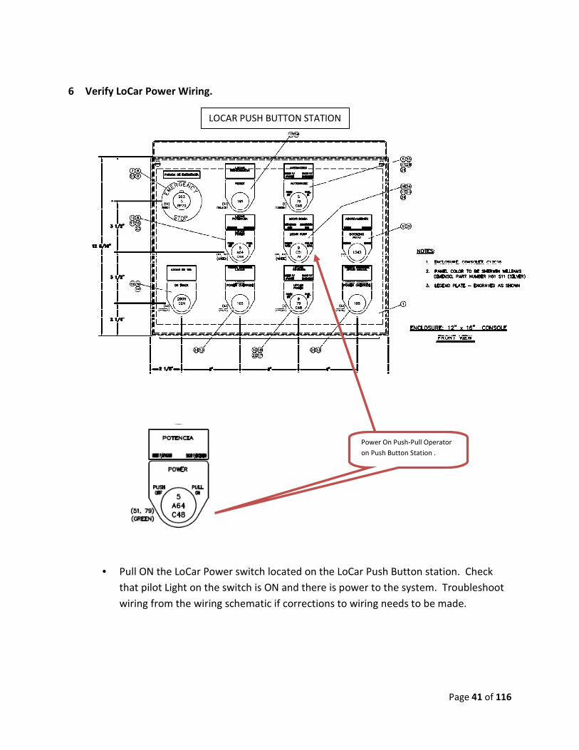
6 Verify LoCar Power Wiring.
• Pull ON the LoCar Power switch located on the LoCar Push Button station. Check
that pilot Light on the switch is ON and there is power to the system. Troubleshoot
wiring from the wiring schematic if corrections to wiring needs to be made.
Power On Push-Pull Operator
on Push Button Station .
LOCAR PUSH BUTTON STATION

Page 42 of 116
7 Verify UpCar Power Wiring.
• Pull ON the UpCar Power switch located on the UpCar PLC panel. Check that pilot
Light on the switch is ON and there is power to the system. Troubleshoot wiring
from the wiring schematic if corrections to wiring needs to be made.
Power On Push-Pull Operator
on Upcar PLC Panel.
UPCAR PLC PANEL
Page 43 of 116
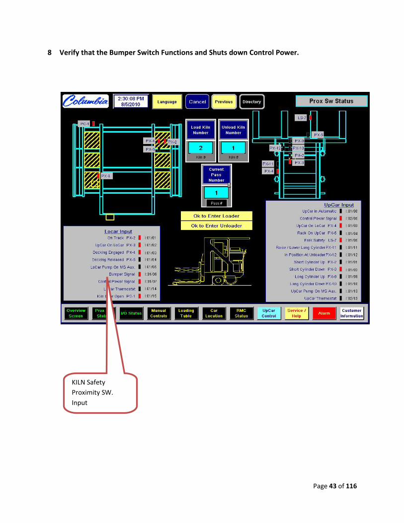
8 Verify that the Bumper Switch Functions and Shuts down Control Power.
KILN Safety
Proximity SW.
Input

Page 44 of 116
9 Verify that the E-Stop Circuit Functions and is wired correctly.
Test the E-Stop circuit by Pushing any E-Stop Button, the system should immediately
shut down. If this event does not occur see the schematic diagram and troubleshoot.
E=Stop On LOCAR &
UPCAR will Illuminate.
Page 45 of 116
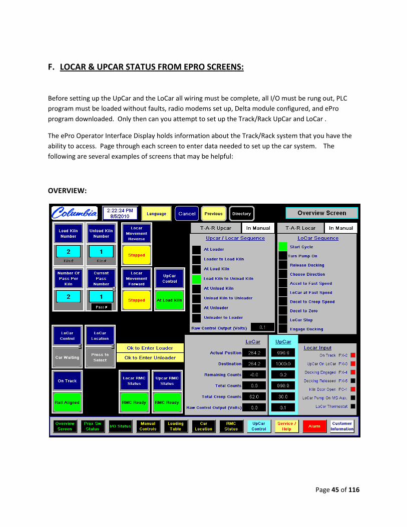
F. LOCAR & UPCAR STATUS FROM EPRO SCREENS:
Before setting up the UpCar and the LoCar all wiring must be complete, all I/O must be rung out, PLC
program must be loaded without faults, radio modems set up, Delta module configured, and ePro
program downloaded. Only then can you attempt to set up the Track/Rack UpCar and LoCar .
The ePro Operator Interface Display holds information about the Track/Rack system that you have the
ability to access. Page through each screen to enter data needed to set up the car system. The
following are several examples of screens that may be helpful:
OVERVIEW:
Page 46 of 116
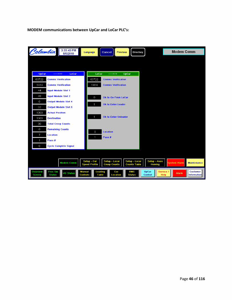
MODEM communications between UpCar and LoCar PLC’s:
Page 47 of 116
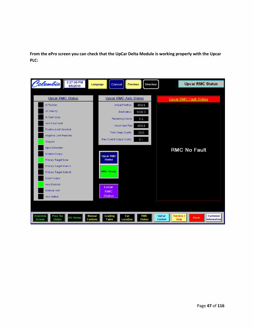
From the ePro screen you can check that the UpCar Delta Module is working properly with the Upcar
PLC:

Page 48 of 116
From the ePro screen you can check that the LoCar Delta Module is working properly with the LoCar
PLC:
Page 49 of 116
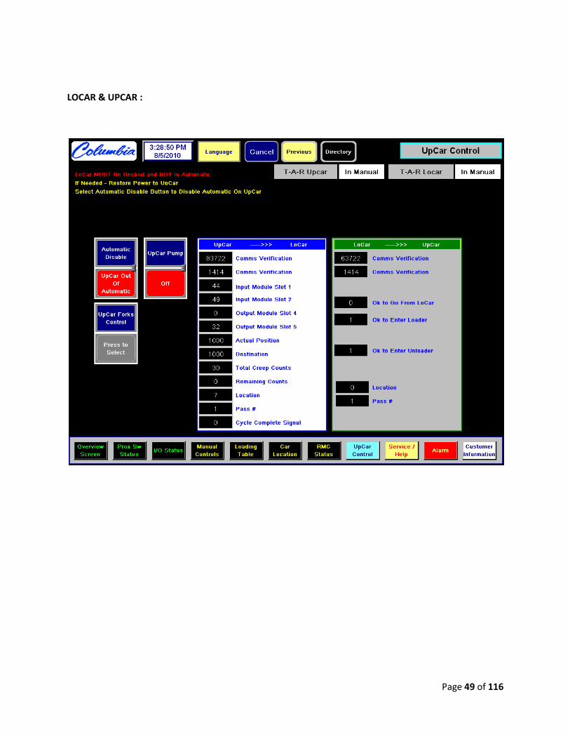
LOCAR & UPCAR :
Page 50 of 116
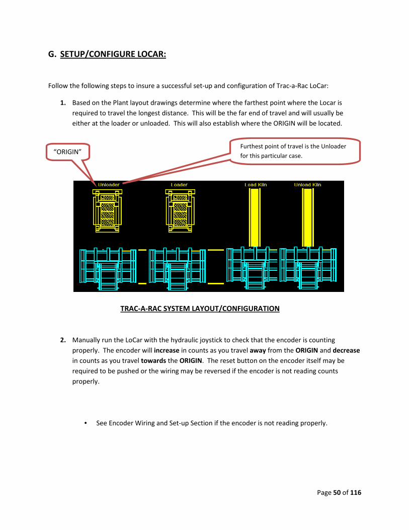
G. SETUP/CONFIGURE LOCAR:
Follow the following steps to insure a successful set-up and configuration of Trac-a-Rac LoCar:
1. Based on the Plant layout drawings determine where the farthest point where the Locar is
required to travel the longest distance. This will be the far end of travel and will usually be
either at the loader or unloaded. This will also establish where the ORIGIN will be located.
TRAC-A-RAC SYSTEM LAYOUT/CONFIGURATION
2. Manually run the LoCar with the hydraulic joystick to check that the encoder is counting
properly. The encoder will increase in counts as you travel away from the ORIGIN and decrease
in counts as you travel towards the ORIGIN. The reset button on the encoder itself may be
required to be pushed or the wiring may be reversed if the encoder is not reading counts
properly.
• See Encoder Wiring and Set-up Section if the encoder is not reading properly.
Furthest point of travel is the Unloader
for this particular case. “ORIGIN”
Page 51 of 116
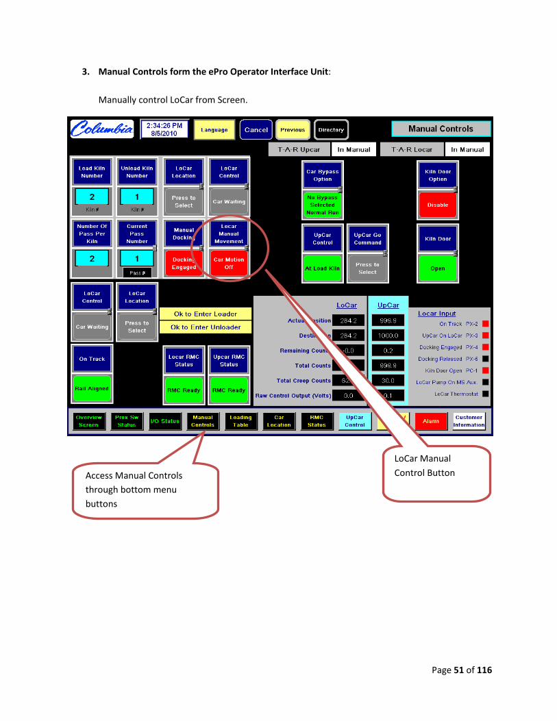
3. Manual Controls form the ePro Operator Interface Unit:
Manually control LoCar from Screen.
LoCar Manual
Control Button Access Manual Controls
through bottom menu
buttons
Page 52 of 116
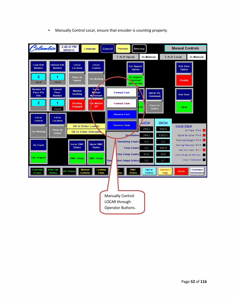
• Manually Control Locar, ensure that encoder is counting properly.
Manually Control
LOCAR through
Operator Buttons.

Page 53 of 116
4. Setup Axis Homing:
Move the Locar to the Loader to set-up PLC axis homing. This procedure sets the starting point
of the PLC at the LOADER.
Reset Locar Encoder Count
In the event of slippage or other conditions that will
cause the encoder count to be slightly off, Park the
Locar at the Unloader and push the “Reset Encoder”
and a known value will be set in the count register.
Page 54 of 116
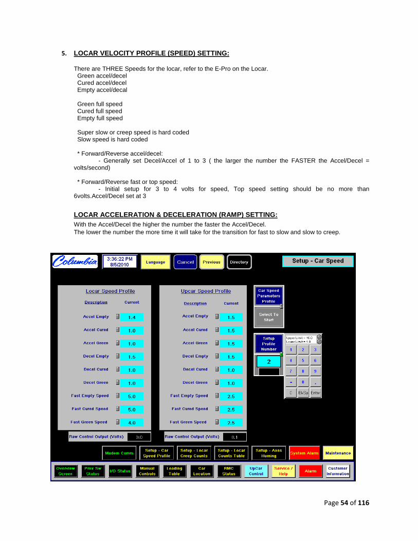
5. LOCAR VELOCITY PROFILE (SPEED) SETTING:
There are THREE Speeds for the locar, refer to the E-Pro on the Locar. Green accel/decel Cured accel/decel Empty accel/decal
Green full speed Cured full speed Empty full speed
Super slow or creep speed is hard coded Slow speed is hard coded * Forward/Reverse accel/decel: - Generally set Decel/Accel of 1 to 3 ( the larger the number the FASTER the Accel/Decel = volts/second) * Forward/Reverse fast or top speed: - Initial setup for 3 to 4 volts for speed, Top speed setting should be no more than 6volts.Accel/Decel set at 3
LOCAR ACCELERATION & DECELERATION (RAMP) SETTING: With the Accel/Decel the higher the number the faster the Accel/Decel. The lower the number the more time it will take for the transition for fast to slow and slow to creep.
Page 55 of 116
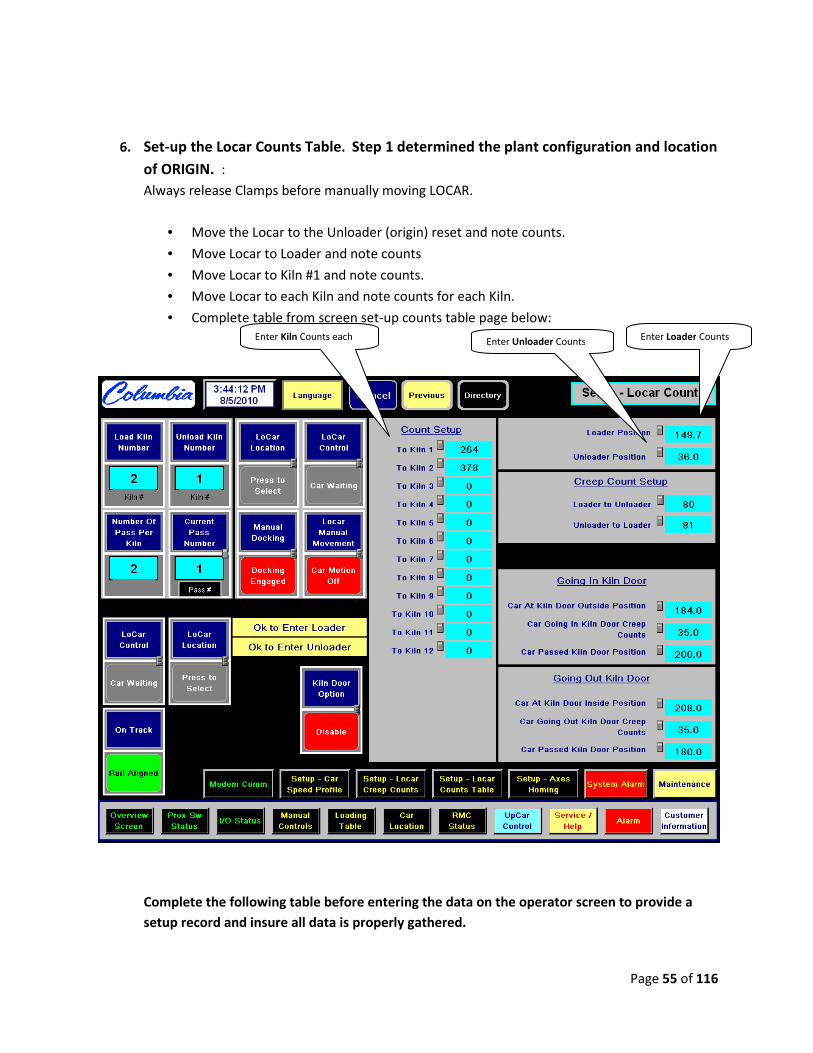
6. Set-up the Locar Counts Table. Step 1 determined the plant configuration and location
of ORIGIN. :
Always release Clamps before manually moving LOCAR.
• Move the Locar to the Unloader (origin) reset and note counts.
• Move Locar to Loader and note counts
• Move Locar to Kiln #1 and note counts.
• Move Locar to each Kiln and note counts for each Kiln.
• Complete table from screen set-up counts table page below:
Complete the following table before entering the data on the operator screen to provide a
setup record and insure all data is properly gathered.
Enter Loader Counts Enter Unloader Counts
Enter Kiln Counts each

Page 56 of 116
Choose the table below based on your Plant Layout and system Configuration:
First table is if the Unloader is the Origin, second table is if the Loader is the Origin.
USE ONLY ONE TABLE.
OR

Page 57 of 116
7. Setup LoCar Creep Count:
Enter values on operator screen shown:
Complete the following tables BELOW FOR EACH SECTION before entering the data on the
operator screen to provide a setup record and insure all data is properly gathered.
FROM LOADER TO
LOAD KILN FROM UNLOAD KILN
TO UNLOADER
FROM LOAD TO
UNLOAD KILN FWD
KILN APART
FROM LOAD TO
UNLOAD KILN REV
KILN APART
Page 58 of 116
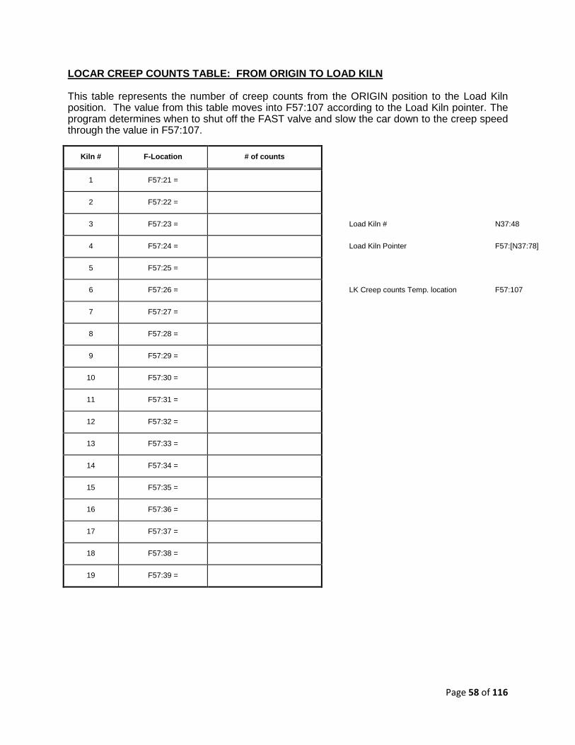
LOCAR CREEP COUNTS TABLE: FROM ORIGIN TO LOAD KILN
This table represents the number of creep counts from the ORIGIN position to the Load Kiln position. The value from this table moves into F57:107 according to the Load Kiln pointer. The program determines when to shut off the FAST valve and slow the car down to the creep speed through the value in F57:107.
Kiln # F-Location # of counts
1 F57:21 =
2 F57:22 =
3 F57:23 = Load Kiln # N37:48
4 F57:24 = Load Kiln Pointer F57:[N37:78]
5 F57:25 =
6 F57:26 = LK Creep counts Temp. location F57:107
7 F57:27 =
8 F57:28 =
9 F57:29 =
10 F57:30 =
11 F57:31 =
12 F57:32 =
13 F57:33 =
14 F57:34 =
15 F57:35 =
16 F57:36 =
17 F57:37 =
18 F57:38 =
19 F57:39 =

Page 59 of 116
LOCAR CREEP COUNTS TABLE: FROM LK TO UK FORWARD
KILNS APART UK# GREATER THAN LK#
This table represents the number of creep counts from the Load Kiln position to the Unload Kiln position. The value from this table moves into F57:108 according to the ( UK # - LK # ) pointer. The program determines when to shut off the FAST valve and slow the car down to the creep speed through the value in F57:108. (UK# > LK#)
Kilns
Apart
F-Location # of counts
1 F57:41 =
2 F57:42 =
3 F57:43 =
4 F57:44 = UK # - LK # Pointer F57:[N37:50]
5 F57:45 =
6 F57:46 = Creep counts Temp. location F57:108
7 F57:47 =
8 F57:48 =
9 F57:49 =
10 F57:50 =
11 F57:51 =
12 F57:52 =
13 F57:53 =
14 F57:54 =
15 F57:55 =
16 F57:56 =
17 F57:57 =
18 F57:58 =
19 F57:59 =

Page 60 of 116
LOCAR CREEP COUNTS TABLE: FROM LK TO UK REVERSE
KILNS APART UK# LESS THAN LK#
This table represents the number of creep counts from the Load Kiln position to the Unload Kiln position. The value from this table moves into F57:112 according to the ( UK # - LK # ) pointer. The program determines when to shut off the FAST valve and slow the car down to the creep speed through the value in F57:112.
Kilns
Apart
F-Location # of counts
1 F57:221 =
2 F57:222 =
3 F57:223 =
4 F57:224 = UK # - LK # Pointer F57:[N37:51]
5 F57:225 =
6 F57:226 = Creep counts Temp. location F57:112
7 F57:227 =
8 F57:228 =
9 F57:229 =
10 F57:230 =
11 F57:231 =
12 F57:232 =
13 F57:233 =
14 F57:234 =
15 F57:235 =
16 F57:236 =
17 F57:237 =
18 F57:238 =
19 F57:239 =

Page 61 of 116
LOCAR CREEP COUNTS TABLE: FROM UK TO UNLOADER
This table represents the number of creep counts from the Unload Kiln position to the UNLOADER position. The value from this table moves into F57:109 according to the Unload Kiln # pointer. The program determines when to shut off the FAST valve and slow the car down to the creep speed through the value in F57:109.
Kiln # F-Location # of counts
1 F57:61 =
2 F57:62 =
3 F57:63 = Unload Kiln # N37:49
4 F57:64 = Unload Kiln # Pointer F57:[N37:80]
5 F57:65 =
6 F57:66 = Creep counts Temp. location F57:109
7 F57:67 =
8 F57:68 =
9 F57:69 =
10 F57:70 =
11 F57:71 =
12 F57:72 =
13 F57:73 =
14 F57:74 =
15 F57:75 =
16 F57:76 =
17 F57:77 =
18 F57:78 =
19 F57:79 =

Page 62 of 116
ALARM TABLE FOR UPCAR AT LOAD KILN
This alarm table represents how long the upcar takes to go into the load kiln to deposit pallets and comes back to the locar. This table changes if you rearrange the PALLET location. The value from this table moves into N87:60 according to the load kiln pass # pointer, N37:30. Then, the value in N87:60 moves into T84:1.PRE in the program. Timer T84:1 starts as soon as the upcar gets off the upcar on locar switch. If the upcar is not getting back onto the locar in the preset amount of time, the alarm turns on to notify the operator. ( 60 = 60.0 sec. )
Pass # N-Location # of counts
1 N87:1 =
2 N87:2 =
3 N87:3 = Load PASS # N37:30
4 N87:4 = Load Kiln # Pointer N87:[N87:20]
5 N87:5 =
6 N87:6 = LK Alarm Temp. location N87:60
7 N87:7 =
8 N87:8 =
9 N87:9 =
10 N87:10 =
11 N87:11 =
12 N87:12 =
13 N87:13 =
14 N87:14 =
15 N87:15 =
16 N87:16 =
17 N87:17 =
18 N87:18 =
19 N87:19 =
Page 63 of 116
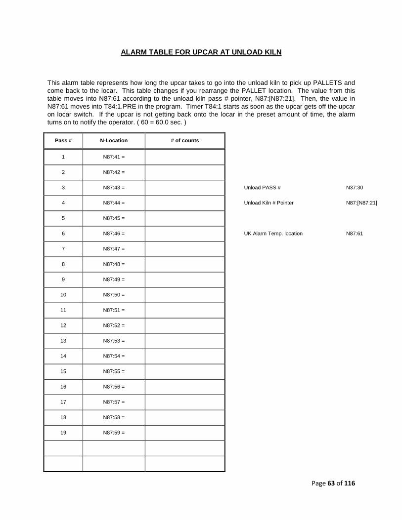
ALARM TABLE FOR UPCAR AT UNLOAD KILN
This alarm table represents how long the upcar takes to go into the unload kiln to pick up PALLETS and come back to the locar. This table changes if you rearrange the PALLET location. The value from this table moves into N87:61 according to the unload kiln pass # pointer, N87:[N87:21]. Then, the value in N87:61 moves into T84:1.PRE in the program. Timer T84:1 starts as soon as the upcar gets off the upcar on locar switch. If the upcar is not getting back onto the locar in the preset amount of time, the alarm turns on to notify the operator. ( 60 = 60.0 sec. )
Pass # N-Location # of counts
1 N87:41 =
2 N87:42 =
3 N87:43 = Unload PASS # N37:30
4 N87:44 = Unload Kiln # Pointer N87:[N87:21]
5 N87:45 =
6 N87:46 = UK Alarm Temp. location N87:61
7 N87:47 =
8 N87:48 =
9 N87:49 =
10 N87:50 =
11 N87:51 =
12 N87:52 =
13 N87:53 =
14 N87:54 =
15 N87:55 =
16 N87:56 =
17 N87:57 =
18 N87:58 =
19 N87:59 =

Page 64 of 116
H. SETUP/CONFIGURE UPCAR:
Follow the following steps to insure a successful set-up and configuration of Trac-A-Rac UpCar :
Based on the Plant layout drawings determine where the farthest point where the Locar is required
to travel the longest distance. This will be the far end of travel and will usually be either at the
loader or unloaded. This will also establish where the ORIGIN will be located.
TRAC-A-RAC SYSTEM LAYOUT/CONFIGURATION
1. Manually run the UpCar with the hydraulic joystick to check that the encoder is counting
properly. The encoder will increase in counts as you travel away from the LoCar and decrease
in counts as you travel towards the LoCar. The reset button on the encoder itself may be
required to be pushed or the wiring may be reversed if the encoder is not reading counts
properly.
• See Encoder Wiring and Set-up Section if the encoder is not reading properly.
Furthest point of travel is the Unloader
for this particular case. “ORIGIN”
Page 65 of 116
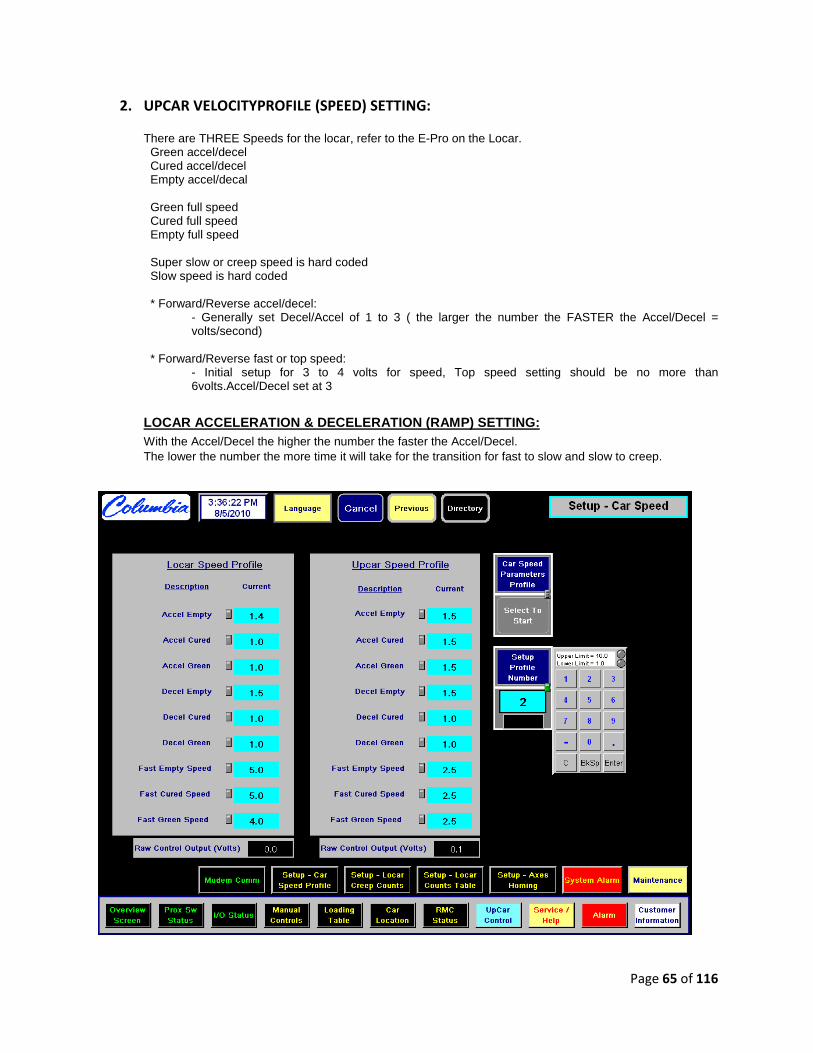
2. UPCAR VELOCITYPROFILE (SPEED) SETTING:
There are THREE Speeds for the locar, refer to the E-Pro on the Locar. Green accel/decel Cured accel/decel Empty accel/decal
Green full speed Cured full speed Empty full speed
Super slow or creep speed is hard coded Slow speed is hard coded * Forward/Reverse accel/decel:
- Generally set Decel/Accel of 1 to 3 ( the larger the number the FASTER the Accel/Decel = volts/second)
* Forward/Reverse fast or top speed:
- Initial setup for 3 to 4 volts for speed, Top speed setting should be no more than 6volts.Accel/Decel set at 3
LOCAR ACCELERATION & DECELERATION (RAMP) SETTING: With the Accel/Decel the higher the number the faster the Accel/Decel. The lower the number the more time it will take for the transition for fast to slow and slow to creep.

Page 66 of 116
3. UPCAR SETUP:
All values/counts needed for setup of the UpCar is to be entered through the UpCar PLC.
The Home position or origin of the Upcar is when the Upcar is on the Locar. Therefore, that position is the reference point or F57:70 = the Actual counts on the E-Pro.
• When the upcar gets to the destination Upcar on Locar and stops, the number in Actual counts represents the number of counts for the Home position (Origin) Upcar/Locar pos..
Locar at the Unload position:
• Manually move the Upcar to the Unload position by operating the E-Pro or Remote. Actual counts should start Increasing as soon as the Upcar moves.
• When the upcar gets to the Stops at the Unloader position, the Actual count represents the number of counts between the Upcar/Locar pos.and the Max unload position.
• Unload position (F57:92) = Actual count. Put this count into the Loader position also • Load position (F57:94) = Actual count.
Manually move the Locar to the Load Kiln.
• Manually move the Upcar to Pass # 1 Kiln #1 position and stop, the number in Actual counts represents the number of counts between the Upcar/Locar and Pass # 1 position.
Pass # 1 position (F57:101) = Actual count.
Reverse the numbers for Unload (F57:121) = Actual count
• Repeat the same procedure until getting to the last Pass # Kiln #1.
To double check, manually move the Upcar in the opposite direction, the Actual count should be
increasing for forward/decreasing for an reverse as soon as the upcar moves. When the upcar
gets back on the Locar, the Actual count should equal the Upcar/Locar position.
The LoCar PLC stores these values in the F registers listed below, fill out count table for verification when setting up.

Page 67 of 116
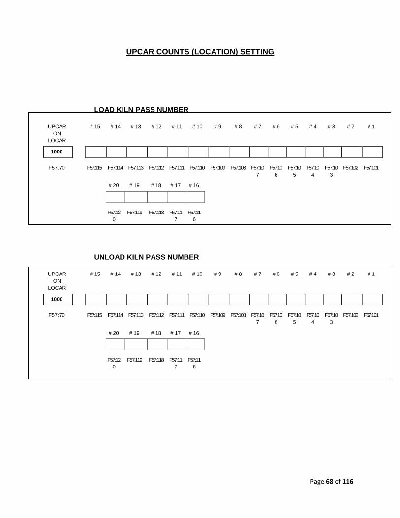
UPCAR COUNTS (LOCATION) SETTING
UPCAR ON
LOCAR
RAISE/
LOWER
CYLINDER POS.
RAISE/
LOWER
CREEP
COUNTS
LOAD POSITION
1000
N57:70 N57:60 N57:61 N57:94
UPCAR ON
LOCAR
RAISE/
LOWER
CYLINDER POS.
RAISE/
LOWER
CREEP
COUNTS
UNLOAD POSITION
1000
N57:70 N57:60 N57:61 N57:92
*** RAISE/LOWER CYCLINDER IS USED BEFORE ENTERING AND AT EXITING LOAD/UNLOAD KILNS FOR
RACK CLEARANCE.
Page 68 of 116
UPCAR COUNTS (LOCATION) SETTING
LOAD KILN PASS NUMBER
UPCAR ON
LOCAR
# 15 # 14 # 13 # 12 # 11 # 10 # 9 # 8 # 7 # 6 # 5 # 4 # 3 # 2 # 1
1000
F57:70 F57:115 F57:114 F57:113 F57:112 F57:111 F57:110 F57:109 F57:108 F57:107
F57:106
F57:105
F57:104
F57:103
F57:102 F57:101
# 20 # 19 # 18 # 17 # 16
F57:12
0 F57:119 F57:118 F57:11
7 F57:11
6
UNLOAD KILN PASS NUMBER
UPCAR ON
LOCAR
# 15 # 14 # 13 # 12 # 11 # 10 # 9 # 8 # 7 # 6 # 5 # 4 # 3 # 2 # 1
1000
F57:70 F57:115 F57:114 F57:113 F57:112 F57:111 F57:110 F57:109 F57:108 F57:107
F57:106
F57:105
F57:104
F57:103
F57:102 F57:101
# 20 # 19 # 18 # 17 # 16
F57:12
0 F57:119 F57:118 F57:11
7 F57:11
6

Page 69 of 116
UPCAR COUNTS TABLE: LOAD POSITION
UPCAR COUNTS TABLE: HOME POSITION (UPCAR ON LOCAR)
F-Location # of counts
F57:70 = Actual COUNT
UPCAR COUNTS TABLE: GOING INTO LOAD COUNTS
This F-Location represents the total number of counts to the correct position for the upcar to pick up the Rack.
F-Location # of counts
F57:94 =
UPCAR COUNTS TABLE: GOING INTO LOAD CREEP COUNTS
This F-Location represents the total number of creep counts to the correct position for the upcar to Drop the Rack.
F-Location # of counts
F57:74 =
UPCAR COUNTS TABLE: GOING OUT OF LOAD CREEP COUNTS
This F-Location represents the total number of creep counts to the Home position (Upcar on Locar) after the upcar picked up the Rack in LOADER Position.
F-Location # of counts
F57:76 =
Page 70 of 116
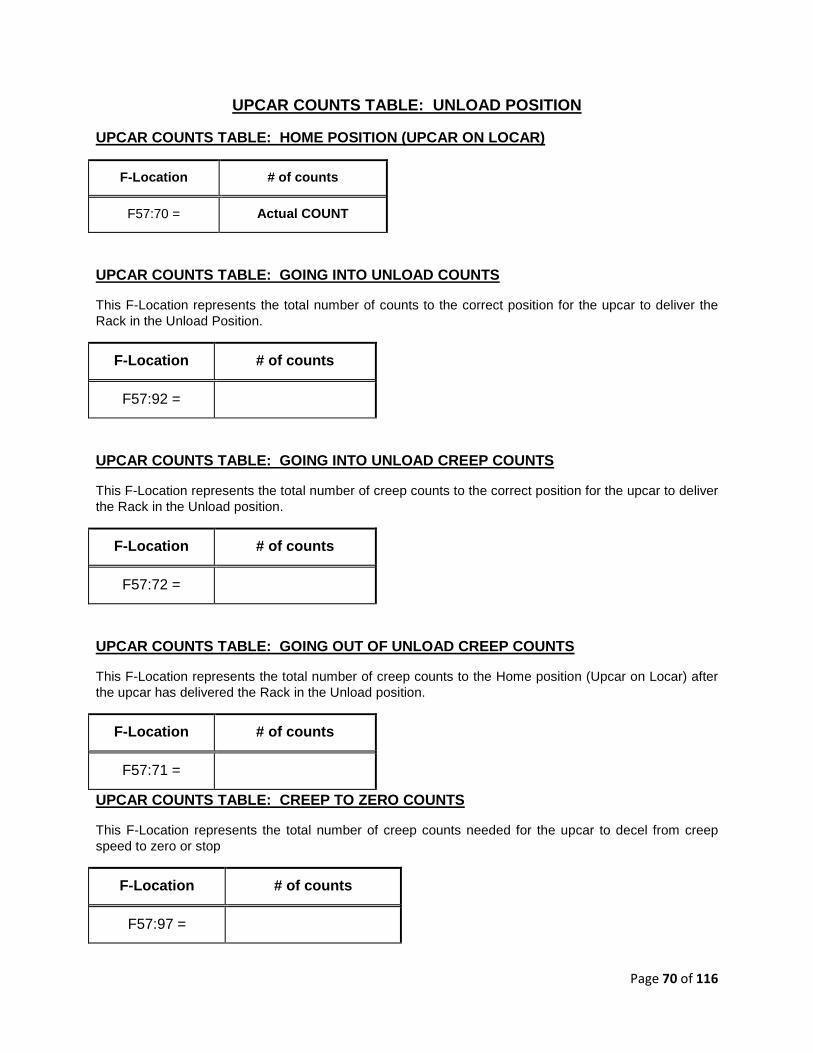
UPCAR COUNTS TABLE: UNLOAD POSITION
UPCAR COUNTS TABLE: HOME POSITION (UPCAR ON LOCAR)
F-Location # of counts
F57:70 = Actual COUNT
UPCAR COUNTS TABLE: GOING INTO UNLOAD COUNTS
This F-Location represents the total number of counts to the correct position for the upcar to deliver the Rack in the Unload Position.
F-Location # of counts
F57:92 =
UPCAR COUNTS TABLE: GOING INTO UNLOAD CREEP COUNTS
This F-Location represents the total number of creep counts to the correct position for the upcar to deliver the Rack in the Unload position.
F-Location # of counts
F57:72 =
UPCAR COUNTS TABLE: GOING OUT OF UNLOAD CREEP COUN TS
This F-Location represents the total number of creep counts to the Home position (Upcar on Locar) after the upcar has delivered the Rack in the Unload position.
F-Location # of counts
F57:71 =
UPCAR COUNTS TABLE: CREEP TO ZERO COUNTS
This F-Location represents the total number of creep counts needed for the upcar to decel from creep speed to zero or stop
F-Location # of counts
F57:97 =
Page 71 of 116
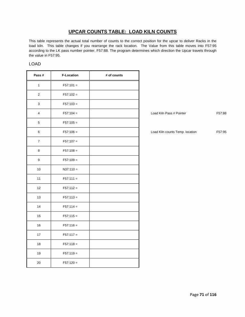
UPCAR COUNTS TABLE: LOAD KILN COUNTS
This table represents the actual total number of counts to the correct position for the upcar to deliver Racks in the load kiln. This table changes if you rearrange the rack location. The Value from this table moves into F57:95 according to the LK pass number pointer, F57:88. The program determines which direction the Upcar travels through the value in F57:95.
LOAD
Pass # F-Location # of counts
1 F57:101 =
2 F57:102 =
3 F57:103 =
4 F57:104 = Load Kiln Pass # Pointer F57:88
5 F57:105 =
6 F57:106 = Load Kiln counts Temp. location F57:95
7 F57:107 =
8 F57:108 =
9 F57:109 =
10 N37:110 =
11 F57:111 =
12 F57:112 =
13 F57:113 =
14 F57:114 =
15 F57:115 =
16 F57:116 =
17 F57:117 =
18 F57:118 =
19 F57:119 =
20 F57:120 =
Page 72 of 116
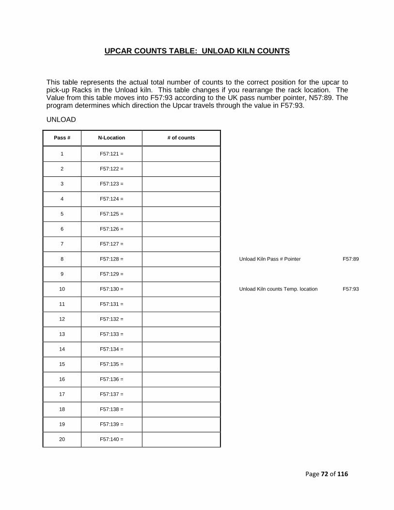
UPCAR COUNTS TABLE: UNLOAD KILN COUNTS
This table represents the actual total number of counts to the correct position for the upcar to pick-up Racks in the Unload kiln. This table changes if you rearrange the rack location. The Value from this table moves into F57:93 according to the UK pass number pointer, N57:89. The program determines which direction the Upcar travels through the value in F57:93.
UNLOAD
Pass # N-Location # of counts
1 F57:121 =
2 F57:122 =
3 F57:123 =
4 F57:124 =
5 F57:125 =
6 F57:126 =
7 F57:127 =
8 F57:128 = Unload Kiln Pass # Pointer F57:89
9 F57:129 =
10 F57:130 = Unload Kiln counts Temp. location F57:93
11 F57:131 =
12 F57:132 =
13 F57:133 =
14 F57:134 =
15 F57:135 =
16 F57:136 =
17 F57:137 =
18 F57:138 =
19 F57:139 =
20 F57:140 =
Page 73 of 116
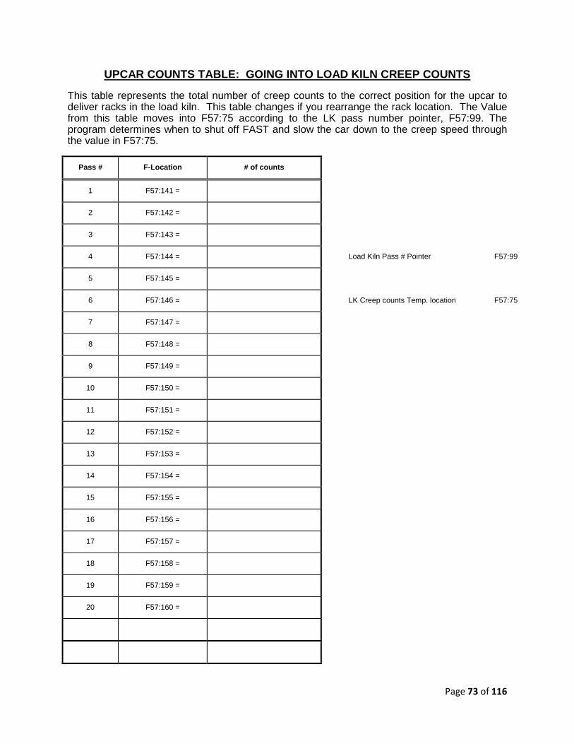
UPCAR COUNTS TABLE: GOING INTO LOAD KILN CREEP COU NTS
This table represents the total number of creep counts to the correct position for the upcar to deliver racks in the load kiln. This table changes if you rearrange the rack location. The Value from this table moves into F57:75 according to the LK pass number pointer, F57:99. The program determines when to shut off FAST and slow the car down to the creep speed through the value in F57:75.
Pass # F-Location # of counts
1 F57:141 =
2 F57:142 =
3 F57:143 =
4 F57:144 = Load Kiln Pass # Pointer F57:99
5 F57:145 =
6 F57:146 = LK Creep counts Temp. location F57:75
7 F57:147 =
8 F57:148 =
9 F57:149 =
10 F57:150 =
11 F57:151 =
12 F57:152 =
13 F57:153 =
14 F57:154 =
15 F57:155 =
16 F57:156 =
17 F57:157 =
18 F57:158 =
19 F57:159 =
20 F57:160 =
Page 74 of 116
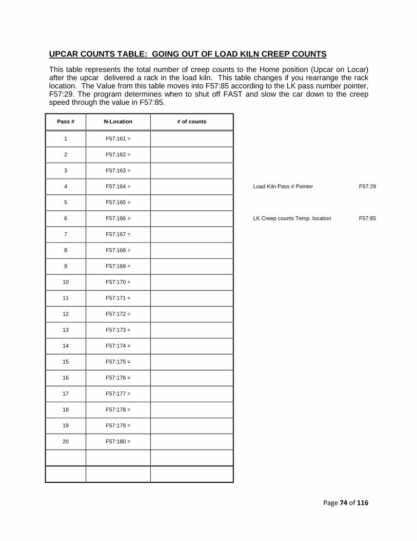
UPCAR COUNTS TABLE: GOING OUT OF LOAD KILN CREEP C OUNTS
This table represents the total number of creep counts to the Home position (Upcar on Locar) after the upcar delivered a rack in the load kiln. This table changes if you rearrange the rack location. The Value from this table moves into F57:85 according to the LK pass number pointer, F57:29. The program determines when to shut off FAST and slow the car down to the creep speed through the value in F57:85.
Pass # N-Location # of counts
1 F57:161 =
2 F57:162 =
3 F57:163 =
4 F57:164 = Load Kiln Pass # Pointer F57:29
5 F57:165 =
6 F57:166 = LK Creep counts Temp. location F57:85
7 F57:167 =
8 F57:168 =
9 F57:169 =
10 F57:170 =
11 F57:171 =
12 F57:172 =
13 F57:173 =
14 F57:174 =
15 F57:175 =
16 F57:176 =
17 F57:177 =
18 F57:178 =
19 F57:179 =
20 F57:180 =

Page 75 of 116
UPCAR COUNTS TABLE: GOING INTO UNLOAD KILN CREEP C OUNTS
This table represents the total number of creep counts to the correct position for the upcar to pick up a rack in the Unload kiln. This table changes if you rearrange the rack location. The Value from this table moves into F57:73 according to the UK pass number pointer, F57:59. The program determines when to shut off FAST and slow the car down to the creep speed through the value in F57:73.
Pass # N-Location # of counts
1 F57:181 =
2 F57:182 =
3 F57:183 =
4 F57:184 = Unload Kiln Pass # Pointer F57:59
5 F57:185 =
6 F57:186 = UK Creep counts Temp. location F57:73
7 F57:187 =
8 F57:188 =
9 F57:189 =
10 F57:190 =
11 F57:191 =
12 F57:192 =
13 F57:193 =
14 F57:194 =
15 F57:195 =
16 F57:196 =
17 F57:197 =
18 F57:198 =
19 F57:199 =
20 F57:200 =

Page 76 of 116
UPCAR COUNTS TABLE: GOING OUT OF UNLOAD KILN CREEP COUNTS
This table represents the total number of creep counts to the Home position (Upcar on Locar) after the upcar has picked up a rack in the Unload kiln. This table changes if you rearrange the rack location. The Value from this table moves into F57:83 according to the UK pass number pointer, F57:98. The program determines when to shut off FAST and slow the car down to the creep speed through the value in F57:83.
Pass # N-Location # of counts
1 F57:201 =
2 F57:202 =
3 F57:203 =
4 F57:204 = Unload Kiln Pass # Pointer F57:98
5 F57:205 =
6 F57:206 = UK Creep counts Temp. location F57:83
7 F57:207 =
8 F57:208 =
9 F57:209 =
10 F57:210 =
11 F57:211 =
12 F57:212 =
13 F57:213 =
14 F57:214 =
15 F57:215 =
16 F57:216 =
17 F57:217 =
18 F57:218 =
19 F57:219 =
20 F57:220 =

Page 77 of 116
I. AUTOMATIC OPERATION OF SYSTEM:
1. AUTOMATIC MODE:
Procedure to put the TRAC-A-RAC systems into AUTOMATIC MODE:
Make sure all preset data are entered into the system before going into to AUTO. These
parameters should all be entered: “Number of Pass Per Kiln”, “Load Kiln Number”,
“Unload Kiln Number”, “Kiln Loading/Unloading Table”.
• Manually move the UpCar onto the LoCar.
• Manually position the LoCar at the Loader.
• Make sure the UpCar Forks are positioned where the Long Cyliner is UP & Short
Cylinder is Down.
• Turn on power to the LoCar at LoCar Push Button Station. “LoCar Power”
• Turn on power to the UpCar at LoCar PLC Control Panel. “UpCar Power”
• Press the Reset Button on the UpCar PLC Control Panel.
• Press the Reset Button on LoCar Push Button Station.
Entered
Data
Page 78 of 116
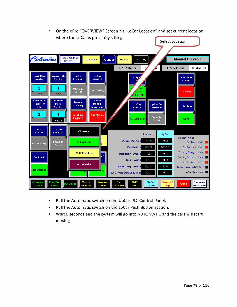
• On the ePro “OVERVIEW” Screen hit “LoCar Location” and set current location
where the LoCar is presently sitting.
• Pull the Automatic switch on the UpCar PLC Control Panel.
• Pull the Automatic switch on the LoCar Push Button Station.
• Wait 6 seconds and the system will go into AUTOMATIC and the cars will start
moving.
Select Location:

Page 79 of 116
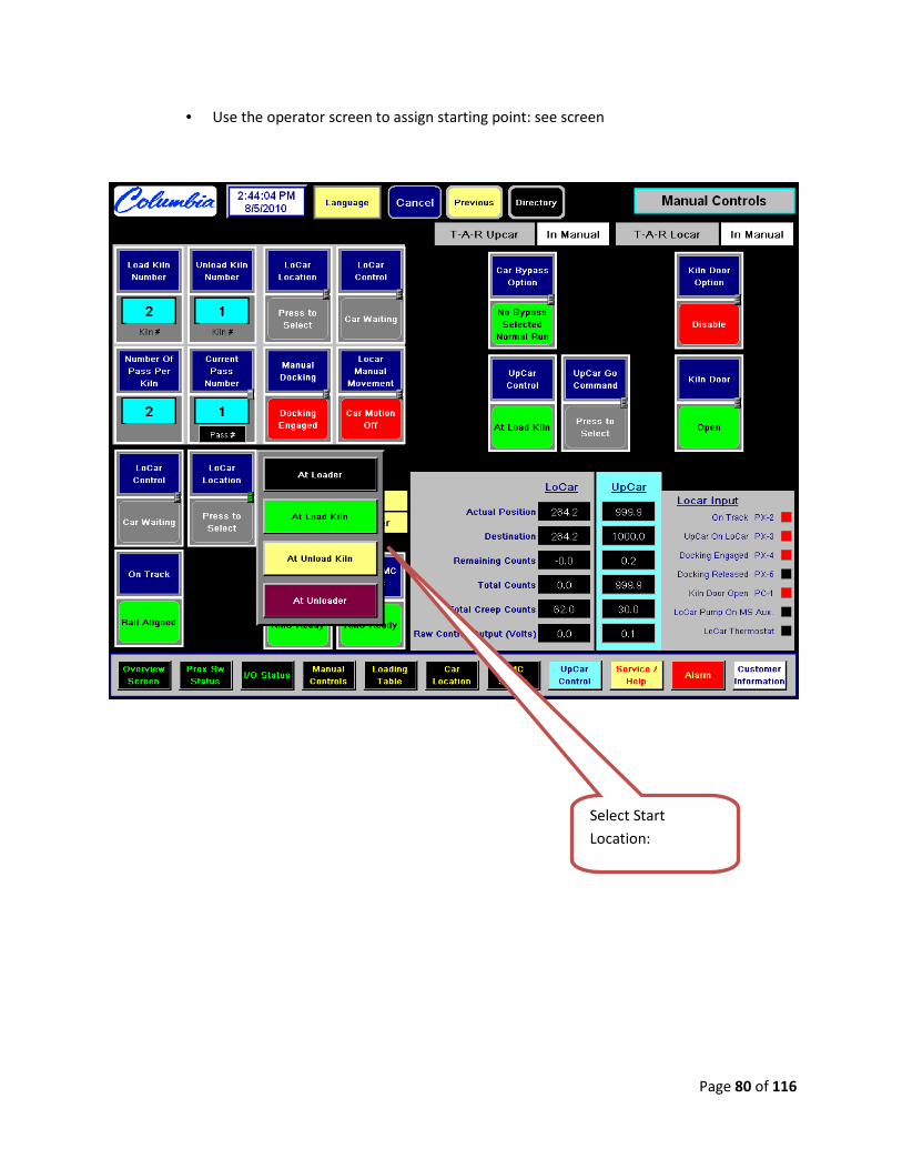
2. FINE TUNING LOCAR:
The LoCar can be fine tuned for optimum performance by simply adjusting creep counts to a
value where the LoCar does not creep for a long length of time and at the same time does not
overshoot its target destination. To Fine tune perform the following:
• Make note of the current creep count at location you are working on:
• Place the system into Auto Mode, See Automatic Mode section for procedure.
Page 80 of 116
• Use the operator screen to assign starting point: see screen
Select Start
Location:
Page 81 of 116
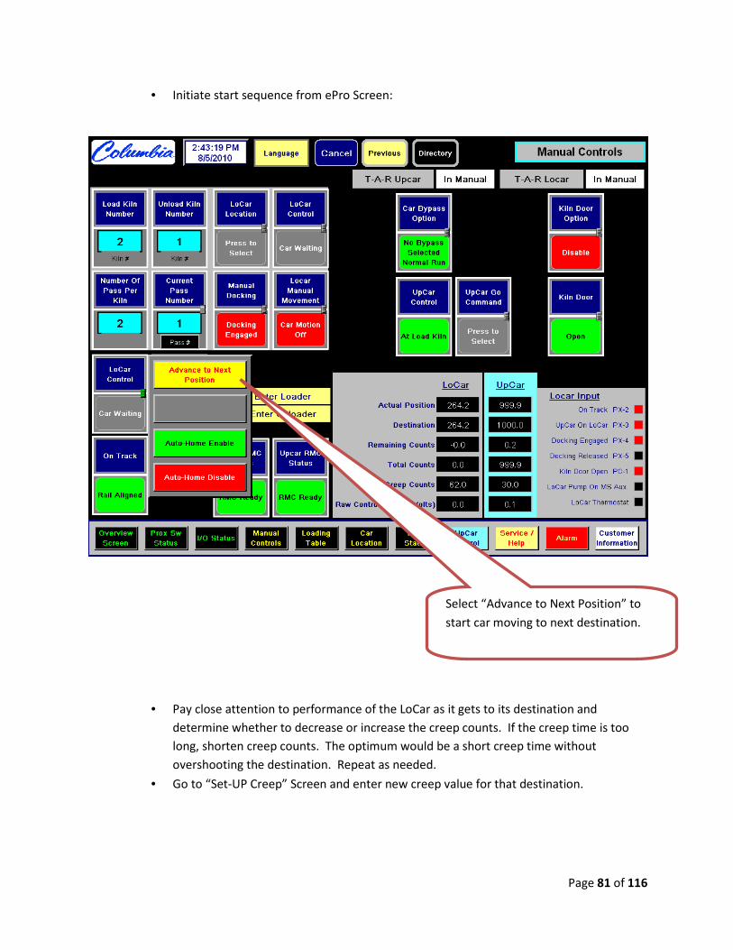
• Initiate start sequence from ePro Screen:
• Pay close attention to performance of the LoCar as it gets to its destination and
determine whether to decrease or increase the creep counts. If the creep time is too
long, shorten creep counts. The optimum would be a short creep time without
overshooting the destination. Repeat as needed.
• Go to “Set-UP Creep” Screen and enter new creep value for that destination.
Select “Advance to Next Position” to
start car moving to next destination.

Page 82 of 116
J. APPENDIX
1.1. General Information:

Page 83 of 116

Page 84 of 116
1.2. PLC Communication Table:
Main PLC w/ MSG Write Instruction to Cars (Lad 3 - rung 4)
Size in Elements 14 Main PLC channel 1
Locar Local Node Address 16
Message Timeout 7 Locar PLC Upcar PLC
Description Main PLC Main PLC Locar PLC Addr. For Addr. For Ucar PLC
local address Address for Address for Modem Modem local
address
MSG instruction MSG
instruction xfer xfer
Pass # to Upcar from
Main N37:30 N137:1 N107:1 O:3.6 I:3.6 N37:40 Load Kiln # to Upcar from
Main N37:48 N137:2 N107:2 O:3.7 I:3.7 N37:48 Unload Kiln # to Upcar
from Main N37:49 N137:3 N107:3 O:3.8 I:3.8 N37:49
OK to GO signal value of '2' or
'0' N137:4 N107:4 O:3.5 I:3.5 '2' or '0'
value Not Used N137:5 N107:5 - - - Not Used N137:6 N107:6 - - - Not Used N137:7 N107:7 - - - Not Used N137:8 N107:8 - - - Not Used N137:9 N107:9 - - -
OK to enter Stacker signal value of '1' or
'0' N137:10 N107:10 O:3.9 I:3.9 '1' or '0'
value OK to enter Unstacker
signal value of '1' or
'0' N137:11 N107:11 O:3.11 I:3.11 '1' or '0'
value
OK to raise Forks in the Stacker signal
value of '1' or '0' N137:12 N107:12 O:3.10 I:3.10
'1' or '0' value
Request Gate Access from Main
value of '1' or '0' N137:13 N107:13
'1' or '0' value - -
Perimeter Gate Closed from Main
value of '1' or '0' N137:14 N107:14
'1' or '0' value - -
Main PLC w/ MSG Write Instruction to Cars (Lad 3 - rung 11)
Size in Elements 1 Main PLC channel 1
Locar Local Node Address 16
Message Timeout 7 Locar PLC Upcar PLC
Description Main PLC Main PLC Locar PLC Addr. For Addr. For Ucar PLC
local address Address for Address for Modem Modem local
address
MSG instruction MSG
instruction xfer xfer
OK to GO signal (B43/36 -
ON) value of '2' or
'0' N137:4 N107:4 O:3.5 I:3.5 '2' or '0'
value
Page 85 of 116
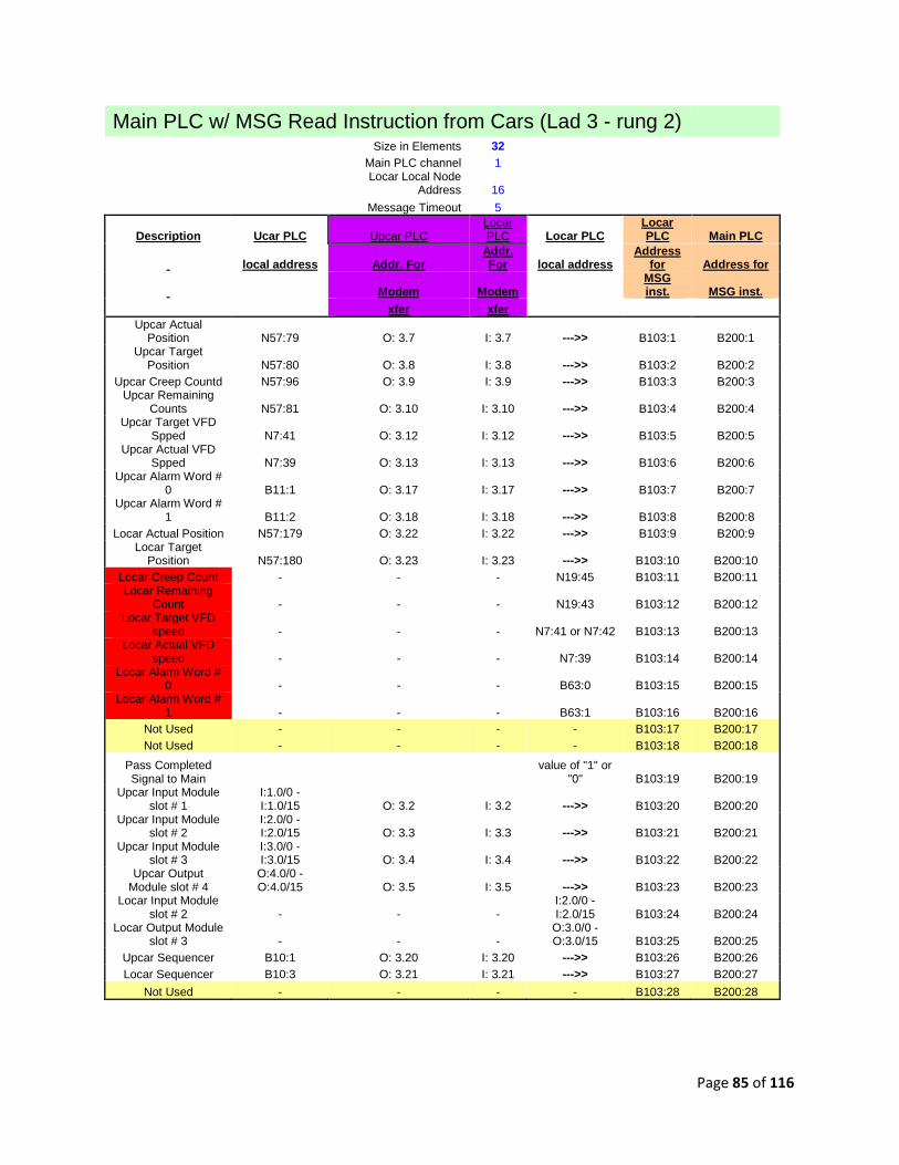
Main PLC w/ MSG Read Instruction from Cars (Lad 3 - rung 2)
Size in Elements 32 Main PLC channel 1 Locar Local Node
Address 16
Message Timeout 5
Description Ucar PLC Upcar PLC Locar PLC Locar PLC
Locar PLC Main PLC
local address Addr. For Addr. For local address
Address for Address for
Modem Modem
MSG inst. MSG inst.
xfer xfer Upcar Actual
Position N57:79 O: 3.7 I: 3.7 --->> B103:1 B200:1 Upcar Target
Position N57:80 O: 3.8 I: 3.8 --->> B103:2 B200:2 Upcar Creep Countd N57:96 O: 3.9 I: 3.9 --->> B103:3 B200:3
Upcar Remaining Counts N57:81 O: 3.10 I: 3.10 --->> B103:4 B200:4
Upcar Target VFD Spped N7:41 O: 3.12 I: 3.12 --->> B103:5 B200:5
Upcar Actual VFD Spped N7:39 O: 3.13 I: 3.13 --->> B103:6 B200:6
Upcar Alarm Word # 0 B11:1 O: 3.17 I: 3.17 --->> B103:7 B200:7
Upcar Alarm Word # 1 B11:2 O: 3.18 I: 3.18 --->> B103:8 B200:8
Locar Actual Position N57:179 O: 3.22 I: 3.22 --->> B103:9 B200:9 Locar Target
Position N57:180 O: 3.23 I: 3.23 --->> B103:10 B200:10 Locar Creep Count - - - N19:45 B103:11 B200:11 Locar Remaining
Count - - - N19:43 B103:12 B200:12 Locar Target VFD
speed - - - N7:41 or N7:42 B103:13 B200:13 Locar Actual VFD
speed - - - N7:39 B103:14 B200:14 Locar Alarm Word #
0 - - - B63:0 B103:15 B200:15 Locar Alarm Word #
1 - - - B63:1 B103:16 B200:16 Not Used - - - - B103:17 B200:17 Not Used - - - - B103:18 B200:18
Pass Completed Signal to Main
value of "1" or "0" B103:19 B200:19
Upcar Input Module slot # 1
I:1.0/0 - I:1.0/15 O: 3.2 I: 3.2 --->> B103:20 B200:20
Upcar Input Module slot # 2
I:2.0/0 - I:2.0/15 O: 3.3 I: 3.3 --->> B103:21 B200:21
Upcar Input Module slot # 3
I:3.0/0 - I:3.0/15 O: 3.4 I: 3.4 --->> B103:22 B200:22
Upcar Output Module slot # 4
O:4.0/0 - O:4.0/15 O: 3.5 I: 3.5 --->> B103:23 B200:23
Locar Input Module slot # 2 - - -
I:2.0/0 - I:2.0/15 B103:24 B200:24
Locar Output Module slot # 3 - - -
O:3.0/0 - O:3.0/15 B103:25 B200:25
Upcar Sequencer B10:1 O: 3.20 I: 3.20 --->> B103:26 B200:26 Locar Sequencer B10:3 O: 3.21 I: 3.21 --->> B103:27 B200:27
Not Used - - - - B103:28 B200:28

Page 86 of 116
Main PLC w/ MSG Read Instruction from Cars (Lad 3 - rung 3)
Size in Elements 1 Main PLC channel 1 Locar Local Node
Address 16 Message Timeout 5
Description Ucar PLC Upcar PLC Locar PLC Locar PLC Locar PLC Main PLC
local address Addr. For Addr. For local
address Address for Address for
Modem Modem
MSG inst. MSG inst.
xfer xfer Upcar / Locar
Comm. Sequencer B60:6 O: 3.19 I: 3.19 --->> B10:1 B200:0
Main PLC w/ MSG Read Instruction from Cars (Lad 3 - rung 5)
Size in Elements 3 Main PLC channel 1 Locar Local Node
Address 16 Message Timeout 7
Description Ucar PLC Upcar PLC Locar PLC Locar PLC Locar PLC Main PLC
local address Addr. For Addr. For local
address Address for Address for
Modem Modem
MSG instruction
MSG instruction
xfer xfer for Confirm -
Pass # from Car to Main N19:46?? I: 3.6 O: 3.6 <<---- N107:1 B25:0
for Confirm - Load Kiln # from
Car to Main N19:18?? I: 3.7 O: 3.7 <<---- N107:2 B25:1 for Confirm - Unload Kiln #
from Car to Main N19:19?? I: 3.8 O: 3.8 <<---- N107:3 B25:2
Page 87 of 116
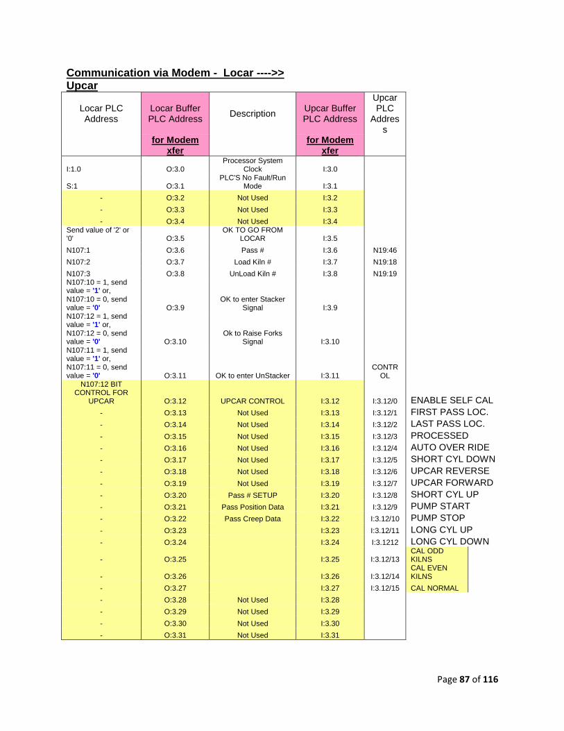
Communication via Modem - Locar ---->> Upcar
Locar PLC Address
Locar Buffer PLC Address
Description Upcar Buffer PLC Address
Upcar PLC
Address
for Modem
xfer for Modem
xfer
I:1.0 O:3.0 Processor System
Clock I:3.0
S:1 O:3.1 PLC'S No Fault/Run
Mode I:3.1
- O:3.2 Not Used I:3.2
- O:3.3 Not Used I:3.3
- O:3.4 Not Used I:3.4 Send value of '2' or '0' O:3.5
OK TO GO FROM LOCAR I:3.5
N107:1 O:3.6 Pass # I:3.6 N19:46
N107:2 O:3.7 Load Kiln # I:3.7 N19:18
N107:3 O:3.8 UnLoad Kiln # I:3.8 N19:19 N107:10 = 1, send value = '1' or, N107:10 = 0, send value = '0' O:3.9
OK to enter Stacker Signal I:3.9
N107:12 = 1, send value = '1' or, N107:12 = 0, send value = '0' O:3.10
Ok to Raise Forks Signal I:3.10
N107:11 = 1, send value = '1' or, N107:11 = 0, send value = '0' O:3.11 OK to enter UnStacker I:3.11
CONTROL
N107:12 BIT CONTROL FOR
UPCAR O:3.12 UPCAR CONTROL I:3.12 I:3.12/0 ENABLE SELF CAL - O:3.13 Not Used I:3.13 I:3.12/1 FIRST PASS LOC. - O:3.14 Not Used I:3.14 I:3.12/2 LAST PASS LOC. - O:3.15 Not Used I:3.15 I:3.12/3 PROCESSED - O:3.16 Not Used I:3.16 I:3.12/4 AUTO OVER RIDE - O:3.17 Not Used I:3.17 I:3.12/5 SHORT CYL DOWN - O:3.18 Not Used I:3.18 I:3.12/6 UPCAR REVERSE - O:3.19 Not Used I:3.19 I:3.12/7 UPCAR FORWARD - O:3.20 Pass # SETUP I:3.20 I:3.12/8 SHORT CYL UP - O:3.21 Pass Position Data I:3.21 I:3.12/9 PUMP START - O:3.22 Pass Creep Data I:3.22 I:3.12/10 PUMP STOP - O:3.23 I:3.23 I:3.12/11 LONG CYL UP - O:3.24 I:3.24 I:3.1212 LONG CYL DOWN
- O:3.25 I:3.25 I:3.12/13 CAL ODD KILNS
- O:3.26 I:3.26 I:3.12/14 CAL EVEN KILNS
- O:3.27 I:3.27 I:3.12/15 CAL NORMAL
- O:3.28 Not Used I:3.28
- O:3.29 Not Used I:3.29
- O:3.30 Not Used I:3.30
- O:3.31 Not Used I:3.31

Page 88 of 116
Communication via Modem - Upcar ---->> Locar
Upcar PLC Address Upcar Buffer PLC Address
Description Locar Buffer PLC Address
Locar PLC
for Modem
xfer for Modem
xfer Address
S:4 O:3.0 Processor System Clock I:3.0 O:6.0
S:1 O:3.1 PLC'S No Fault/Run Mode I:3.1 N7:11
I:1.0/0 - I:1.0/15 O:3.2 Upcar Input Module slot # 1 I:3.2 B103:20
I:2.0/0 - I:2.0/15 O:3.3 Upcar Input Module slot # 2 I:3.3 B103:21
I:3.0/0 - I:3.0/15 O:3.4 Upcar Input Module slot # 3 I:3.4 B103:22
O:4.0/0 - O:4.0/15 O:3.5 Upcar Output Module slot #
4 I:3.5 B103:23
N7:20 O:3.6 Laser Signal (mA) I:3.6 Not Used
N57:179 O:3.7 Upcar Actual Position
(Count) I:3.7 B103:1
N57:80 O:3.8 Upcar Target Position
(Count) I:3.8 B103:2
N57:96 O:3.9 Upcar Creep Count I:3.9 B103:3
N57:81 O:3.10 Upcar Remaining Count I:3.10 B103:4
N7:45 O:3.11 Upcar VFD Output (mA) I:3.11 Not Used
N7:41 O:3.12 Target VFD Speed (Hz) I:3.12 B103:5
N7:39 O:3.13 Actual VFD Speed (Hz) I:3.13 B103:6
B3/65 - Send fork up, value = '4' B3/67 - Send fork down, value = '7' O:3.14
Upcar Location - Verify for Forks position I:3.14 Not Used
N37:40 O:3.15 Pass Number Verify I:3.15 Not Used
B10/8 - Unstkr to Stkr or, B60/109 - Travel to Stacker, send value = '2' O:3.16 Cycle Complete I:3.16
To Main - B103:19
B11:1 - see 'upcar alarm' worksheet O:3.17 Upcar Alarm Word # 0 I:3.17 B103:7
B11:2 - see 'upcar alarm' worksheet O:3.18 Upcar Alarm Word # 1 I:3.18 B103:8
B60:6 - see 'Upcar Sequencer desc.' worksheet O:3.19
Upcar / Locar Communication
Sequence Drum Word I:3.19 B10:1 B10:1 - see 'Upcar Sequencer desc.' worksheet O:3.20 Upcar Sequence Drum Word I:3.20 B10:3 - see 'Upcar Sequencer desc.' worksheet O:3.21 Locar Sequence Drum Word I:3.21

Page 89 of 116
Upcar Alarm Word # 0 - B11:1 Main PLC
Address
B200:7/0 B11:1/0 B11/16 Upcar over travel alarm B200:7/1 B11:1/1 B11/17 Upcar Interlock alarm B200:7/2 B11:1/2 B11/18 Unused B200:7/3 B11:1/3 B11/19 Unused B200:7/4 B11:1/4 B11/20 Unused B200:7/5 B11:1/5 B11/21 Unused B200:7/6 B11:1/6 B11/22 Unused B200:7/7 B11:1/7 B11/23 Unused B200:7/8 B11:1/8 B11/24 Unused B200:7/9 B11:1/9 B11/25 Unused B200:7/10 B11:1/10 B11/26 Unused B200:7/11 B11:1/11 B11/27 Unused B200:7/12 B11:1/12 B11/28 Unused B200:7/13 B11:1/13 B11/29 Unused B200:7/14 B11:1/14 B11/30 Encoder failure alarm B200:7/15 B11:1/15 B11/31 Upcar not on Locar alarm Upcar Alarm Word # 1 - B11:2 B200:8/0 B11:2/0 B11/32 Forks not up alarm B200:8/1 B11:2/1 B11/33 Forks not down alarm B200:8/2 B11:2/2 B11/34 Kiln Door not open alarm B200:8/3 B11:2/3 B11/35 Pallet safety alarm B200:8/4 B11:2/4 B11/36 Upcar hydraulic pump not on alarm B200:8/5 B11:2/5 B11/37 Upcar drive contactor not enable alarm B200:8/6 B11:2/6 B11/38 Locar drive contactor not enable alarm B200:8/7 B11:2/7 B11/39 Upcar cable reel motion sensor 'ON' timer alarm B200:8/8 B11:2/8 B11/40 Upcar cable reel motion sensor 'OFF' timer alarm B200:8/9 B11:2/9 B11/41 Locar count # that car is going to is less than 1 B200:8/10 B11:2/10 B11/42 Laser alarm timer enable B200:8/11 B11:2/11 B11/43 Upcar not moving alarm B200:8/12 B11:2/12 B11/44 Laser sensor loss of signal alarm B200:8/13 B11:2/13 B11/45 Laser sensor over travel alarm B200:8/14 B11:2/14 B11/46 Unused B200:8/15 B11:2/15 B11/47 Unused

Page 90 of 116
Main PLC Address Upcar / Locar Sequencer - UPCAR PLC
B15/320 B60:6/0 B60/96 Unused B15/321 B60:6/1 B60/97 Unused B15/322 B60:6/2 B60/98 Unused B15/323 B60:6/3 B60/99 Unused B15/324 B60:6/4 B60/100 Unused B15/325 B60:6/5 B60/101 Check Interlocks B15/326 B60:6/6 B60/102 At Stacker B15/327 B60:6/7 B60/103 Travel to Load Kiln B15/328 B60:6/8 B60/104 At Load Kiln B15/329 B60:6/9 B60/105 Travel to Unload Kiln B15/330 B60:6/10 B60/106 At Unload Kiln B15/331 B60:6/11 B60/107 Travel to Unstacker B15/332 B60:6/12 B60/108 At Unstacker B15/333 B60:6/13 B60/109 Travel to Stacker B15/334 B60:6/14 B60/110 Bypass # 1 to Unstacker B15/335 B60:6/15 B60/111 Bypass # 1 At Unstacker B15/336 B60:7/0 B60/112 Bypass Load Kiln to Stacker B15/337 B60:7/1 B60/113 Unused B15/338 B60:7/2 B60/114 Unused B15/339 B60:7/3 B60/115 Unused B15/340 B60:7/4 B60/116 Unused B15/341 B60:7/5 B60/117 Unused B15/342 B60:7/6 B60/118 Unused B15/343 B60:7/7 B60/119 Unused B15/344 B60:7/8 B60/120 Unused B15/345 B60:7/9 B60/121 Unused B15/346 B60:7/10 B60/122 Unused B15/347 B60:7/11 B60/123 Unused B15/348 B60:7/12 B60/124 Unused B15/349 B60:7/13 B60/125 Unused B15/350 B60:7/14 B60/126 Unused B15/351 B60:7/15 B60/127 Unused
Page 91 of 116
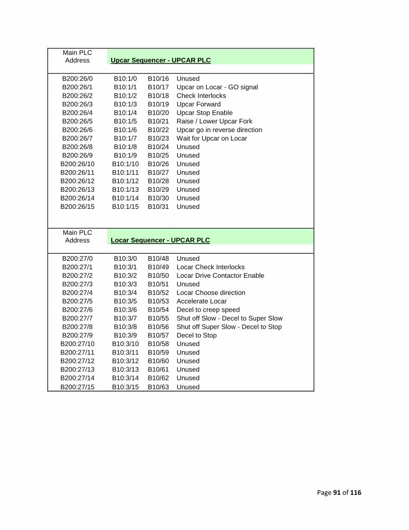
Main PLC Address Upcar Sequencer - UPCAR PLC
B200:26/0 B10:1/0 B10/16 Unused B200:26/1 B10:1/1 B10/17 Upcar on Locar - GO signal B200:26/2 B10:1/2 B10/18 Check Interlocks B200:26/3 B10:1/3 B10/19 Upcar Forward B200:26/4 B10:1/4 B10/20 Upcar Stop Enable B200:26/5 B10:1/5 B10/21 Raise / Lower Upcar Fork B200:26/6 B10:1/6 B10/22 Upcar go in reverse direction B200:26/7 B10:1/7 B10/23 Wait for Upcar on Locar B200:26/8 B10:1/8 B10/24 Unused B200:26/9 B10:1/9 B10/25 Unused B200:26/10 B10:1/10 B10/26 Unused B200:26/11 B10:1/11 B10/27 Unused B200:26/12 B10:1/12 B10/28 Unused B200:26/13 B10:1/13 B10/29 Unused B200:26/14 B10:1/14 B10/30 Unused B200:26/15 B10:1/15 B10/31 Unused
Main PLC Address Locar Sequencer - UPCAR PLC
B200:27/0 B10:3/0 B10/48 Unused B200:27/1 B10:3/1 B10/49 Locar Check Interlocks B200:27/2 B10:3/2 B10/50 Locar Drive Contactor Enable B200:27/3 B10:3/3 B10/51 Unused B200:27/4 B10:3/4 B10/52 Locar Choose direction B200:27/5 B10:3/5 B10/53 Accelerate Locar B200:27/6 B10:3/6 B10/54 Decel to creep speed B200:27/7 B10:3/7 B10/55 Shut off Slow - Decel to Super Slow B200:27/8 B10:3/8 B10/56 Shut off Super Slow - Decel to Stop B200:27/9 B10:3/9 B10/57 Decel to Stop B200:27/10 B10:3/10 B10/58 Unused B200:27/11 B10:3/11 B10/59 Unused B200:27/12 B10:3/12 B10/60 Unused B200:27/13 B10:3/13 B10/61 Unused B200:27/14 B10:3/14 B10/62 Unused B200:27/15 B10:3/15 B10/63 Unused

Page 92 of 116
1.3. Trouble Shooting TAR:
PROCEDURE FOR RESETTING & PUTTING THE TAR UPCAR IN AUTOMATIC:
Upcar lost power at Loader – going in to pick up the rack:
1. Take Locar out of Auto by pushing in the AUTOMATIC button on the Locar Pushbutton
Station.
2. Pull on UPCAR POWER button on the Locar Pushbutton Station and PUSH E-STOP ENABLE on
Starter Panel.
3. Manually bring the Upcar back to the Locar.
Make sure the Upcar Forks are in the LONG UP/ SHORT DOWN position.
4. Check Locar Panelmate for Load Kiln #, Unload Kiln #, and Pass # on page 2.
5. Reset the Locar by pressing the RESET button on the Locar control panel.
6. Confirm the information:
• Load Kiln #.
• Unload Kiln #.
• Pass #.
7. Reset the Upcar by pressing the RESET button on the Upcar Control Panel.
8. Put Upcar in Automatic by pulling on the AUTOMATIC button on the Upcar Control Panel.
9. Put Locar in Automatic by pulling on the AUTOMATIC button on the Locar P.B. Station.
Upcar lost power at Loader – going back to Locar with the rack:
NOTE: DO NOT RESET LOCAR
1. Take Locar out of Auto by pushing in the AUTOMATIC button on the Locar P.B. Station.
Pull on UPCAR POWER button on the Locar P.B. Station and PUSH E-STOP ENABLE on Starter
Panel.
2. Manually bring the Upcar back to the Locar.
Make sure the Upcar Forks are in the LONG UP/ SHORT DOWN position.
3. Reset the Upcar by pressing the RESET button on the Upcar Control Panel.
4. Put Upcar in Automatic by pulling on the AUTOMATIC button on the Upcar Control Panel.
Page 93 of 116
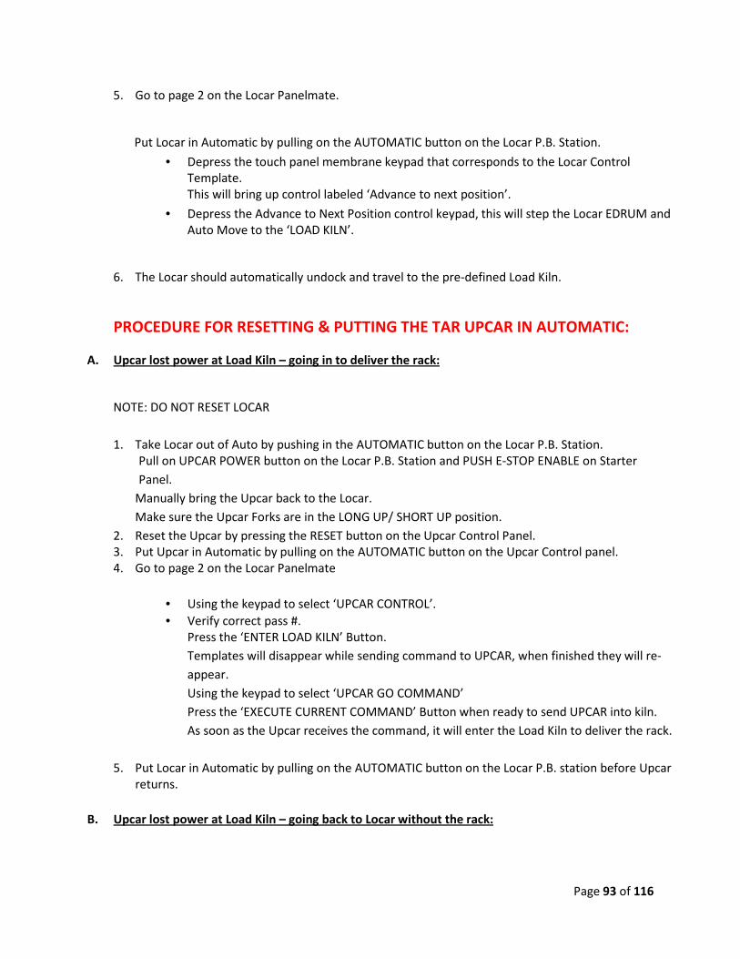
5. Go to page 2 on the Locar Panelmate.
Put Locar in Automatic by pulling on the AUTOMATIC button on the Locar P.B. Station.
• Depress the touch panel membrane keypad that corresponds to the Locar Control
Template.
This will bring up control labeled ‘Advance to next position’.
• Depress the Advance to Next Position control keypad, this will step the Locar EDRUM and
Auto Move to the ‘LOAD KILN’.
6. The Locar should automatically undock and travel to the pre-defined Load Kiln.
PROCEDURE FOR RESETTING & PUTTING THE TAR UPCAR IN AUTOMATIC:
A. Upcar lost power at Load Kiln – going in to deliver the rack:
NOTE: DO NOT RESET LOCAR
1. Take Locar out of Auto by pushing in the AUTOMATIC button on the Locar P.B. Station.
Pull on UPCAR POWER button on the Locar P.B. Station and PUSH E-STOP ENABLE on Starter
Panel.
Manually bring the Upcar back to the Locar.
Make sure the Upcar Forks are in the LONG UP/ SHORT UP position.
2. Reset the Upcar by pressing the RESET button on the Upcar Control Panel.
3. Put Upcar in Automatic by pulling on the AUTOMATIC button on the Upcar Control panel.
4. Go to page 2 on the Locar Panelmate
• Using the keypad to select ‘UPCAR CONTROL’.
• Verify correct pass #.
Press the ‘ENTER LOAD KILN’ Button.
Templates will disappear while sending command to UPCAR, when finished they will re-
appear.
Using the keypad to select ‘UPCAR GO COMMAND’
Press the ‘EXECUTE CURRENT COMMAND’ Button when ready to send UPCAR into kiln.
As soon as the Upcar receives the command, it will enter the Load Kiln to deliver the rack.
5. Put Locar in Automatic by pulling on the AUTOMATIC button on the Locar P.B. station before Upcar
returns.
B. Upcar lost power at Load Kiln – going back to Locar without the rack:

Page 94 of 116
NOTE: DO NOT RESET LOCAR
1. Take Locar out of Auto by pushing in the AUTOMATIC button on the Locar P.B. station.
Pull on UPCAR POWER button on the Locar P.B. Station and PUSH E-STOP ENABLE on Starter
Panel.
2. Manually bring the Upcar back to the Locar.
Make sure the Upcar Forks are in the LONG UP/ SHORT DOWN position.
3. Reset the Upcar by pressing the RESET button on the Upcar Control Panel.
4. Put Upcar in Automatic by pulling on the AUTOMATIC button on the Upcar Control Panel.
5. Go to page 2 on the Locar Panelmate.
• Drum #1 template should display ‘AT LOAD KILN’.
• Depress the touch panel membrane keypad that says ‘LOCAR CONTROL.
This will bring up control labeled ‘Advance to next Position’.
Put Locar in Automatic by pulling on the AUTOMATIC button on the Locar P.B. Station.
• Depress the Advance to next Position control keypad, this will step the Locar
EDRUM until the template display ‘LOAD KILN TO UNLOAD KILN’.
6. The Locar should automatically undock and travel to the pre-defined Unload Kiln.
C. Upcar lost power at Unload Kiln – going in to pick up the rack:
NOTE: DO NOT RESET LOCAR
1. Take Locar out of Auto by pushing in the AUTOMATIC button on the Locar P.B. Station.
Pull on UPCAR POWER button on the Locar P.B. Station and PUSH E-STOP ENABLE on Starter
Panel.
2. Manually bring the Upcar back to the Locar.
Make sure the Upcar Forks are in the LONG UP/ SHORT DOWN position.
3. Reset the Upcar by pressing the RESET button on the Upcar Control Panel.
4. Put Upcar in Automatic by pulling on the AUTOMATIC button on the Upcar Control Panel.
5. Go to page 2 on the Locar Panelmate, Position template should display ‘AT UNLOAD KILN’.
6. On the Locar Panelmate
• Using the keypad to select ‘UPCAR CONTROL’.
• Verify correct pass #.
Press the ‘ENTER UNLOAD KILN’ Button.
Templates will disappear while sending command to UPCAR, when finished they will re-
appear.
• Using the keypad to select ‘UPCAR GO COMMAND’
Press the ‘EXECUTE CURRENT COMMAND’ Button when ready to send UPCAR into kiln.
As soon as the Upcar receives the command, it will enter the UnLoad Kiln to pick-up the
rack.
Page 95 of 116
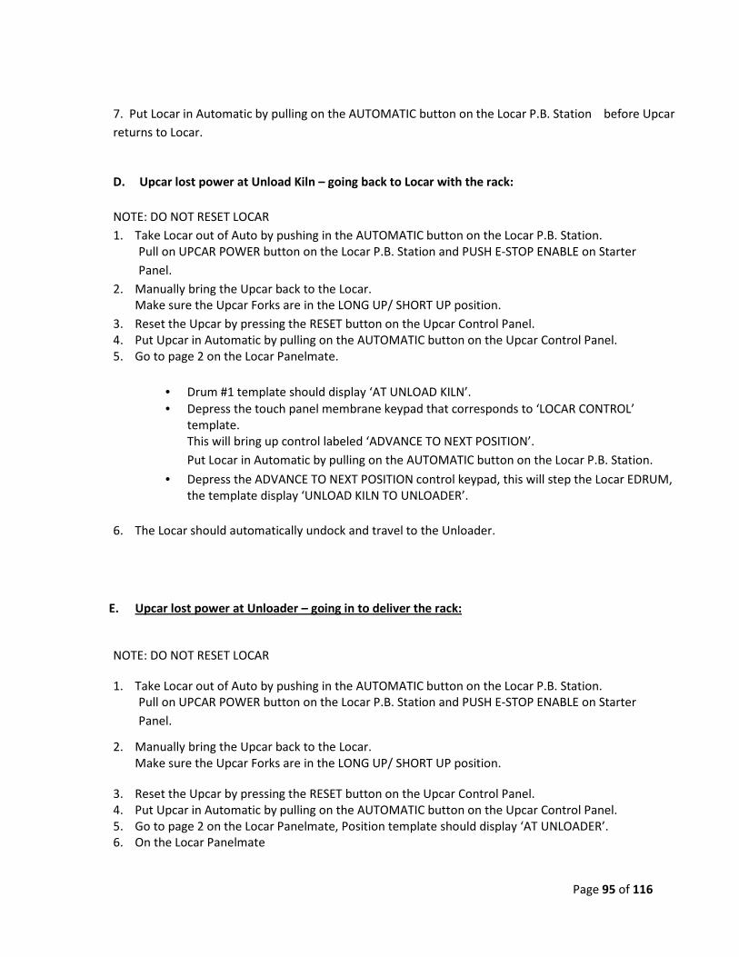
7. Put Locar in Automatic by pulling on the AUTOMATIC button on the Locar P.B. Station before Upcar
returns to Locar.
D. Upcar lost power at Unload Kiln – going back to Locar with the rack:
NOTE: DO NOT RESET LOCAR
1. Take Locar out of Auto by pushing in the AUTOMATIC button on the Locar P.B. Station.
Pull on UPCAR POWER button on the Locar P.B. Station and PUSH E-STOP ENABLE on Starter
Panel.
2. Manually bring the Upcar back to the Locar.
Make sure the Upcar Forks are in the LONG UP/ SHORT UP position.
3. Reset the Upcar by pressing the RESET button on the Upcar Control Panel.
4. Put Upcar in Automatic by pulling on the AUTOMATIC button on the Upcar Control Panel.
5. Go to page 2 on the Locar Panelmate.
• Drum #1 template should display ‘AT UNLOAD KILN’.
• Depress the touch panel membrane keypad that corresponds to ‘LOCAR CONTROL’
template.
This will bring up control labeled ‘ADVANCE TO NEXT POSITION’.
Put Locar in Automatic by pulling on the AUTOMATIC button on the Locar P.B. Station.
• Depress the ADVANCE TO NEXT POSITION control keypad, this will step the Locar EDRUM,
the template display ‘UNLOAD KILN TO UNLOADER’.
6. The Locar should automatically undock and travel to the Unloader.
E. Upcar lost power at Unloader – going in to deliver the rack:
NOTE: DO NOT RESET LOCAR
1. Take Locar out of Auto by pushing in the AUTOMATIC button on the Locar P.B. Station.
Pull on UPCAR POWER button on the Locar P.B. Station and PUSH E-STOP ENABLE on Starter
Panel.
2. Manually bring the Upcar back to the Locar.
Make sure the Upcar Forks are in the LONG UP/ SHORT UP position.
3. Reset the Upcar by pressing the RESET button on the Upcar Control Panel.
4. Put Upcar in Automatic by pulling on the AUTOMATIC button on the Upcar Control Panel.
5. Go to page 2 on the Locar Panelmate, Position template should display ‘AT UNLOADER’.
6. On the Locar Panelmate

Page 96 of 116
• Using the keypad to select ‘UPCAR CONTROL’.
Press the ‘ENTER UNLOADER’ Button.
Templates will disappear while sending command to UPCAR, when finished they will re-
appear.
Using the keypad to select ‘UPCAR GO COMMAND’
Press the ‘EXECUTE CURRENT COMMAND’ Button when ready to send UPCAR into
UnLoader.
As soon as the Upcar receives the command, it will enter the UnLoader to deliver the rack.
7. Put Locar in Automatic by pulling on the AUTOMATIC button on the Locar P.B. Station before Upcar
returns to Locar.
F. Upcar lost power at Unloader – going back to Locar without the rack:
NOTE: DO NOT RESET LOCAR
1. Take Locar out of Auto by pushing in the AUTOMATIC button on the Locar P.B. Station.
Pull on UPCAR POWER button on the Locar P.B. Station and PUSH E-STOP ENABLE on Starter
Panel.
2. Manually bring the Upcar back to the Locar.
Make sure the Upcar Forks are in the LONG UP/ SHORT DOWN position.
3. Reset the Upcar by pressing the RESET button on the Upcar Control Panel.
4. Put Upcar in Automatic by pulling on the AUTOMATIC button on the Upcar Control Panel.
5. Go to page 2 on the Locar Panelmate.
• Drum #1 template should display ‘AT UNLOADER’.
• Depress the touch panel membrane keypad that corresponds to the ‘LOCAR CONTROL’
template.
This will bring up control labeled ‘ADVANCE TO NEXT POSITION’.
Put Locar in Automatic by pulling on the AUTOMATIC button on the Locar P.B. Station.
• Depress the ADVANCE TO NEXT POSITION control keypad, this will step the Locar EDRUM
until the template display ‘UNLOADER TO LOADER’.
6. The Locar should automatically undock and travel to the Loader.
Page 97 of 116
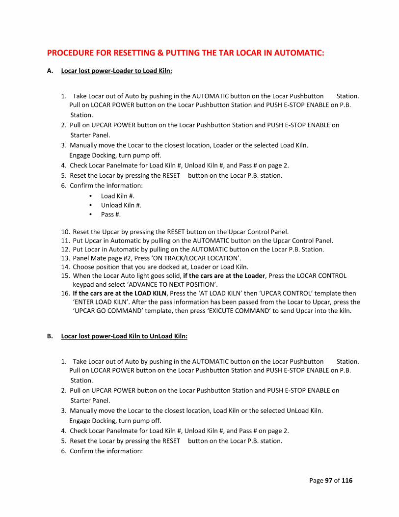
PROCEDURE FOR RESETTING & PUTTING THE TAR LOCAR IN AUTOMATIC:
A. Locar lost power-Loader to Load Kiln:
1. Take Locar out of Auto by pushing in the AUTOMATIC button on the Locar Pushbutton Station.
Pull on LOCAR POWER button on the Locar Pushbutton Station and PUSH E-STOP ENABLE on P.B.
Station.
2. Pull on UPCAR POWER button on the Locar Pushbutton Station and PUSH E-STOP ENABLE on
Starter Panel.
3. Manually move the Locar to the closest location, Loader or the selected Load Kiln.
Engage Docking, turn pump off.
4. Check Locar Panelmate for Load Kiln #, Unload Kiln #, and Pass # on page 2.
5. Reset the Locar by pressing the RESET button on the Locar P.B. station.
6. Confirm the information:
• Load Kiln #.
• Unload Kiln #.
• Pass #.
10. Reset the Upcar by pressing the RESET button on the Upcar Control Panel.
11. Put Upcar in Automatic by pulling on the AUTOMATIC button on the Upcar Control Panel.
12. Put Locar in Automatic by pulling on the AUTOMATIC button on the Locar P.B. Station.
13. Panel Mate page #2, Press ‘ON TRACK/LOCAR LOCATION’.
14. Choose position that you are docked at, Loader or Load Kiln.
15. When the Locar Auto light goes solid, if the cars are at the Loader, Press the LOCAR CONTROL
keypad and select ‘ADVANCE TO NEXT POSITION’.
16. If the cars are at the LOAD KILN, Press the ‘AT LOAD KILN’ then ‘UPCAR CONTROL’ template then
‘ENTER LOAD KILN’. After the pass information has been passed from the Locar to Upcar, press the
‘UPCAR GO COMMAND’ template, then press ‘EXICUTE COMMAND’ to send Upcar into the kiln.
B. Locar lost power-Load Kiln to UnLoad Kiln:
1. Take Locar out of Auto by pushing in the AUTOMATIC button on the Locar Pushbutton Station.
Pull on LOCAR POWER button on the Locar Pushbutton Station and PUSH E-STOP ENABLE on P.B.
Station.
2. Pull on UPCAR POWER button on the Locar Pushbutton Station and PUSH E-STOP ENABLE on
Starter Panel.
3. Manually move the Locar to the closest location, Load Kiln or the selected UnLoad Kiln.
Engage Docking, turn pump off.
4. Check Locar Panelmate for Load Kiln #, Unload Kiln #, and Pass # on page 2.
5. Reset the Locar by pressing the RESET button on the Locar P.B. station.
6. Confirm the information:
Page 98 of 116
• Load Kiln #.
• Unload Kiln #.
• Pass #.
7. Reset the Upcar by pressing the RESET button on the Upcar Control Panel.
8. Put Upcar in Automatic by pulling on the AUTOMATIC button on the Upcar Control Panel.
9. Put Locar in Automatic by pulling on the AUTOMATIC button on the Locar P.B. Station.
10. Panel Mate page #2, Press ‘ON TRACK/LOCAR LOCATION’.
11. Choose position that you are docked at, Load Kiln or UnLoad Kiln.
12. When the Locar Auto light goes solid, if the cars are at the Load Kiln, Press the LOCAR CONTROL
keypad and select ‘ADVANCE TO NEXT POSITION’.
13. If the cars are at the UnLoad Kiln, Press the ‘AT UNLOAD KILN’ then ‘UPCAR CONTROL’ template
then ‘ENTER UNLOAD KILN’. After the pass information has been passed from the Locar to Upcar,
press the ‘UPCAR GO COMMAND’ template, then press ‘EXICUTE COMMAND’ to send Upcar into the
kiln.
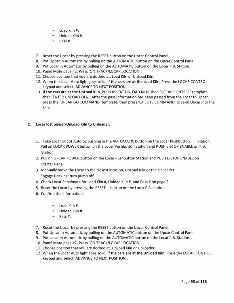
C. Locar lost power-UnLoad Kiln to Unloader:
1. Take Locar out of Auto by pushing in the AUTOMATIC button on the Locar Pushbutton Station.
Pull on LOCAR POWER button on the Locar Pushbutton Station and PUSH E-STOP ENABLE on P.B.
Station.
2. Pull on UPCAR POWER button on the Locar Pushbutton Station and PUSH E-STOP ENABLE on
Starter Panel.
3. Manually move the Locar to the closest location, UnLoad Kiln or the UnLoader.
Engage Docking, turn pump off.
4. Check Locar Panelmate for Load Kiln #, Unload Kiln #, and Pass # on page 2.
5. Reset the Locar by pressing the RESET button on the Locar P.B. station.
6. Confirm the information:
• Load Kiln #.
• Unload Kiln #.
• Pass #.
7. Reset the Upcar by pressing the RESET button on the Upcar Control Panel.
8. Put Upcar in Automatic by pulling on the AUTOMATIC button on the Upcar Control Panel.
9. Put Locar in Automatic by pulling on the AUTOMATIC button on the Locar P.B. Station.
10. Panel Mate page #2, Press ‘ON TRACK/LOCAR LOCATION’.
11. Choose position that you are docked at, UnLoad Kiln or UnLoader.
12. When the Locar Auto light goes solid, if the cars are at the UnLoad Kiln, Press the LOCAR CONTROL
keypad and select ‘ADVANCE TO NEXT POSITION’.
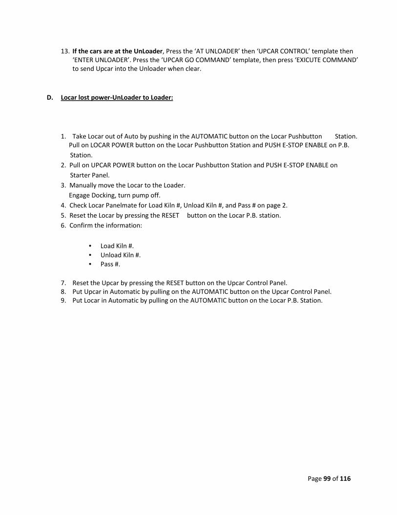
Page 99 of 116
13. If the cars are at the UnLoader, Press the ‘AT UNLOADER’ then ‘UPCAR CONTROL’ template then
‘ENTER UNLOADER’. Press the ‘UPCAR GO COMMAND’ template, then press ‘EXICUTE COMMAND’
to send Upcar into the Unloader when clear.
D. Locar lost power-UnLoader to Loader:
1. Take Locar out of Auto by pushing in the AUTOMATIC button on the Locar Pushbutton Station.
Pull on LOCAR POWER button on the Locar Pushbutton Station and PUSH E-STOP ENABLE on P.B.
Station.
2. Pull on UPCAR POWER button on the Locar Pushbutton Station and PUSH E-STOP ENABLE on
Starter Panel.
3. Manually move the Locar to the Loader.
Engage Docking, turn pump off.
4. Check Locar Panelmate for Load Kiln #, Unload Kiln #, and Pass # on page 2.
5. Reset the Locar by pressing the RESET button on the Locar P.B. station.
6. Confirm the information:
• Load Kiln #.
• Unload Kiln #.
• Pass #.
7. Reset the Upcar by pressing the RESET button on the Upcar Control Panel.
8. Put Upcar in Automatic by pulling on the AUTOMATIC button on the Upcar Control Panel.
9. Put Locar in Automatic by pulling on the AUTOMATIC button on the Locar P.B. Station.

Page 100 of 116
1.4. Service/Help Screen in Epro:
Access Service/Help
Screeen.
Set up car Speed
Profile.
Set up Locar Creep
Counts.
Set up Locar Counts
Table

Page 101 of 116
1.5. Shutting Down Epro
Go to the Service/Help Screen ;
1..Service/Help
Screen 2. Select “Exit Program” to Quit
Epro.
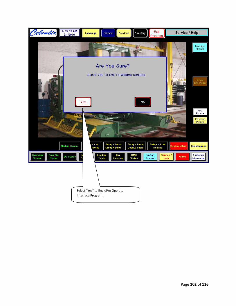
Page 102 of 116
Select “Yes” to End ePro Operator
Interface Program.
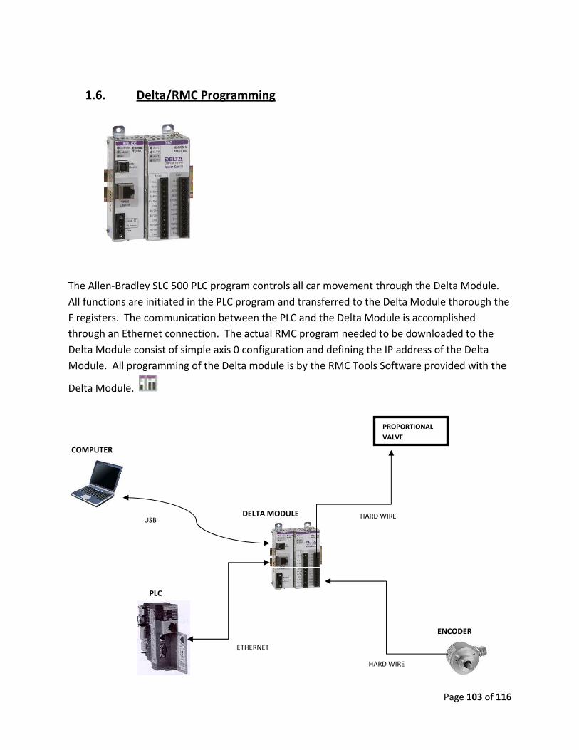
Page 103 of 116
1.6. Delta/RMC Programming
The Allen-Bradley SLC 500 PLC program controls all car movement through the Delta Module.
All functions are initiated in the PLC program and transferred to the Delta Module thorough the
F registers. The communication between the PLC and the Delta Module is accomplished
through an Ethernet connection. The actual RMC program needed to be downloaded to the
Delta Module consist of simple axis 0 configuration and defining the IP address of the Delta
Module. All programming of the Delta module is by the RMC Tools Software provided with the
Delta Module.
PROPORTIONAL
VALVE
ETHERNET
USB HARD WIRE
HARD WIRE
COMPUTER
PLC
DELTA MODULE
ENCODER
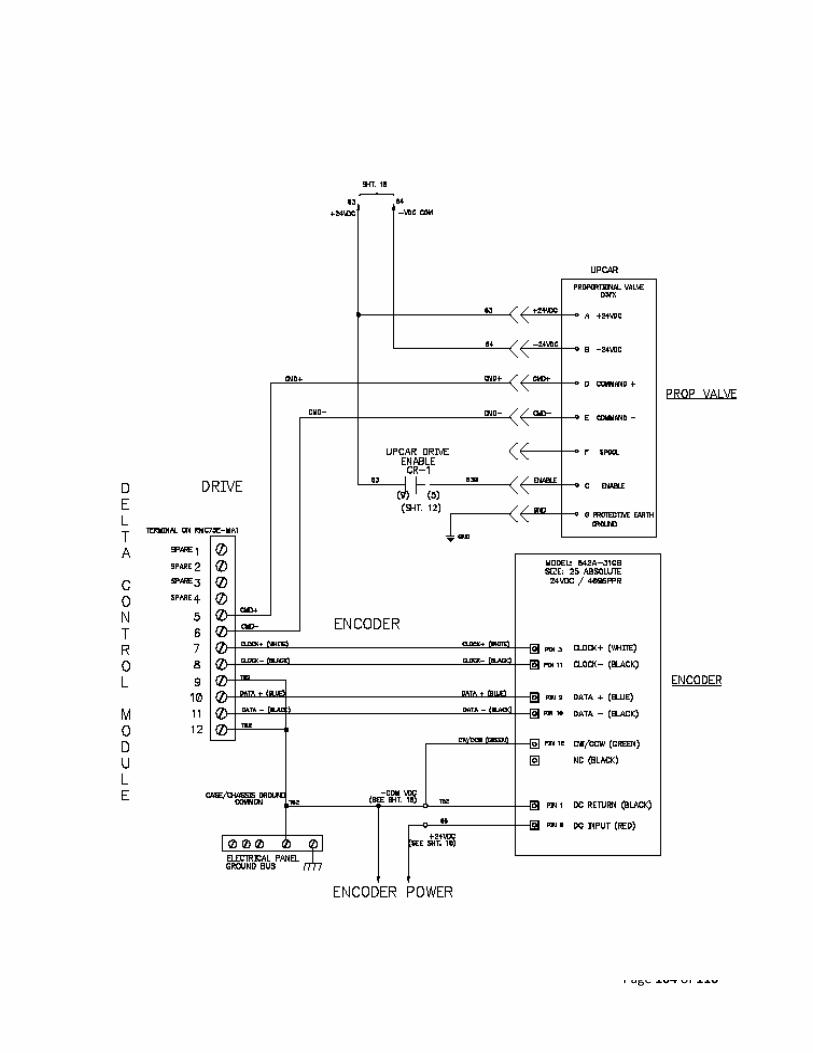
Page 104 of 116

Page 105 of 116
PLC And Delta Module Address Map:
Communication Between PLC And RMC
PLC Address
RMC Indirect Address Description
Units of Measurement
F8.0 F18:0 (F8:0) Axis0 Status Bits F8.1 F18:1 (F8:1) Axis0 Error Bits F8.2 F18:2 (F8:8) Axis0 Actual Position pos-units F8.3 F18:3 (F8:9) Axis0 Actual Velocity pos-units/sec F8.4 F18:4 (F8:10) Axis0 Actual Accel pos-units/sec² F8.5 F18:5 (F8:11) Axis0 Counts counts F8.6 F18:6 (F8:12) Axis0 Raw Counts raw counts F8.7 F18:7 (F8:33) Axis0 Control Output Volts F8.8 F18:8 (F12:1) Axis0 Position Offset pos-units F8.9 F18:9 F41.0 F18:10 (F16:0) Axis0 Command Area-10 for Open loop F41.1 F18:11 (F16:1) Axis0 Command Par. 1-Volts to Proportional Val F41.2 F18:12 (F16:2) Axis0 Command Par. 2-Accel/Decel Open Loop F41.3 F18:13 (F16:3) Axis0 Command Par. 3 F41.4 F18:14 (F16:4) Axis0 Command Par. 4 F41.5 F18:15 (F16:5) Axis0 Command Par. 5
F18:16 F18:17 F18:18 F18:19 F18:20 (F8:53) Axis0 Target Position pos-units F18:21 (F8:54) Axis0 Target Velocity pos-units/sec F18:22 (F8:55) Axis0 Target Accel pos-units/sec² F18:23 (F8:56) Axis0 Command Position pos-units F18:24 (F8:57) Axis0 Command Velocity pos-units/sec F18:25 F18:26
F41:0 Axis Command Area – Trac a Rac command = 10 for open loop. RMC card controls proportional
valve by applying voltage.
F41:1 Axis Command Parameter #1 = applying voltage (velocity) to proportional valve
F41:2 Axis Command Parameter #2 = deceleration and Acceleration in open loop command as mention
in F41:0

Page 106 of 116
PLC Read from Delta Module:
• Plc program section showing message instruction to read from Delta card read registers
and transfer data to PLC registers.
Plc Write to Delta Module:
PLC Read from Delta
Module.
Read 8 Elements from Delta
Card & store in PLC reg. F8.0
Read From Delta Module
Reg. F18.0
Read Delta module IP
Address.
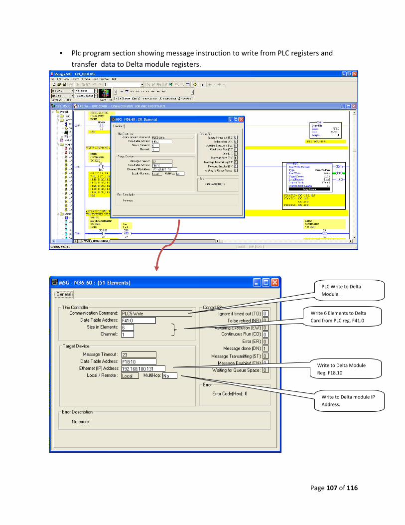
Page 107 of 116
• Plc program section showing message instruction to write from PLC registers and
transfer data to Delta module registers.
PLC Write to Delta
Module.
Write 6 Elements to Delta
Card from PLC reg. F41.0
Write to Delta Module
Reg. F18.10
Write to Delta module IP
Address.

Page 108 of 116
Program/Configure Delta Module with RMC Tools programming software:
The RMC Tools programming software is provided with the Delta module along with the
purchase of the card.
RMC Tools Software Version:
5. Run Delta Module RMC Tools Software:
RMCTOOLS
VERSION
Axis Tools Configure the Axis
Parameter Section
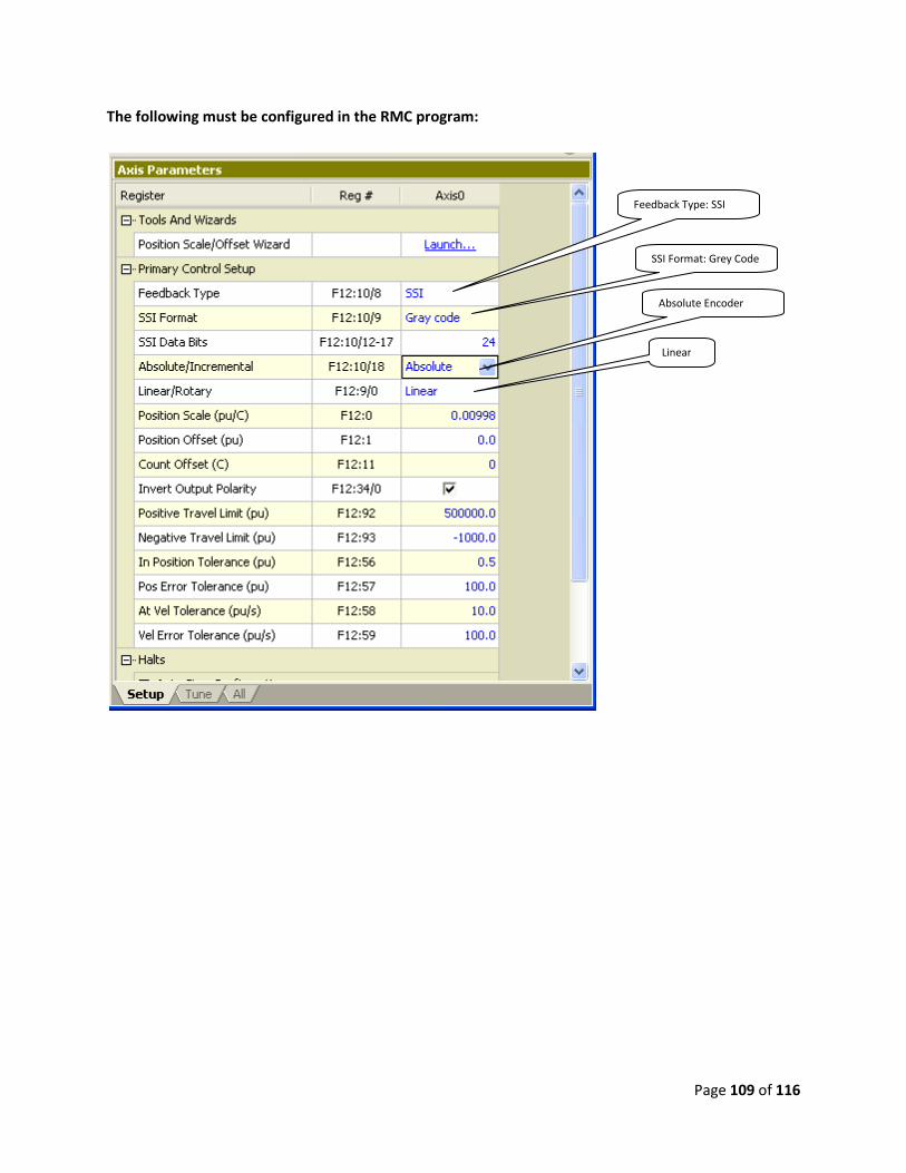
Page 109 of 116
The following must be configured in the RMC program:
Feedback Type: SSI
SSI Format: Grey Code
Absolute Encoder
Linear
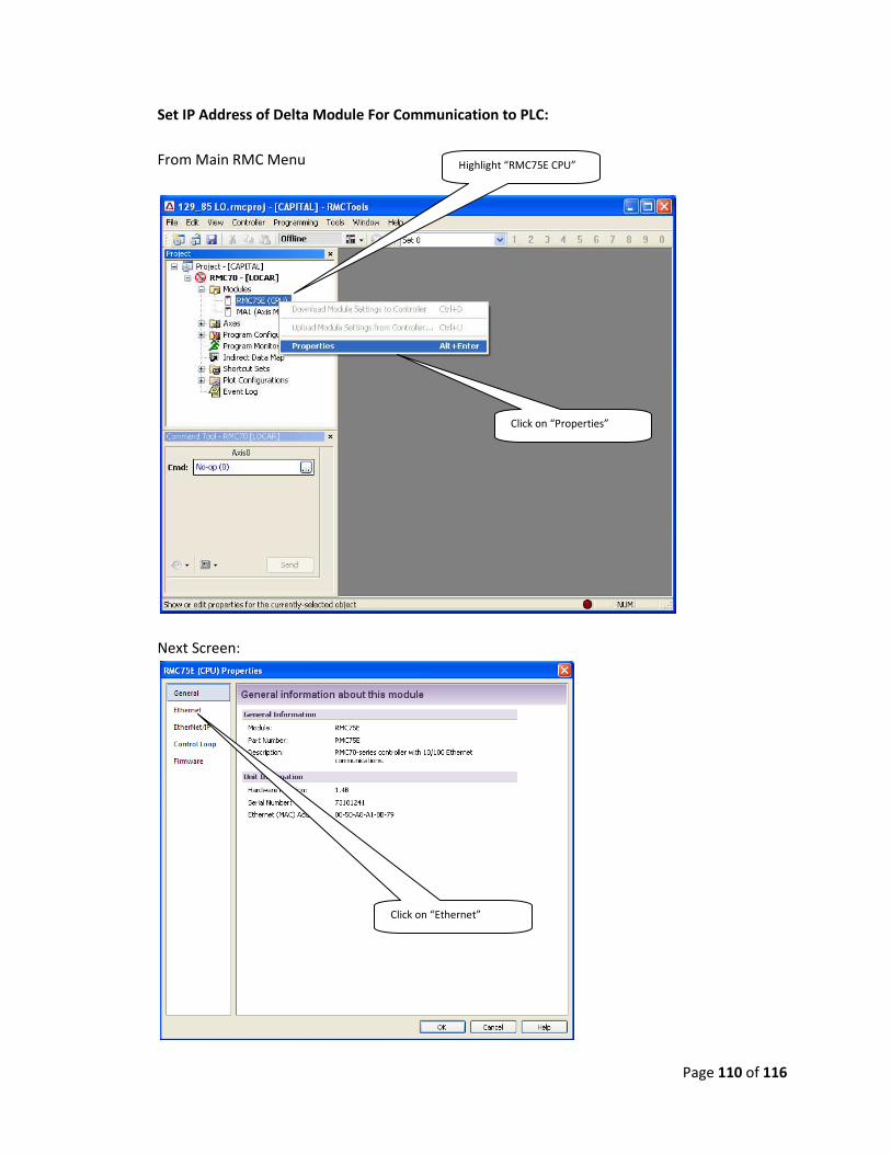
Page 110 of 116
Set IP Address of Delta Module For Communication to PLC:
From Main RMC Menu
Next Screen:
Highlight “RMC75E CPU”
Click on “Properties”
Click on “Ethernet”
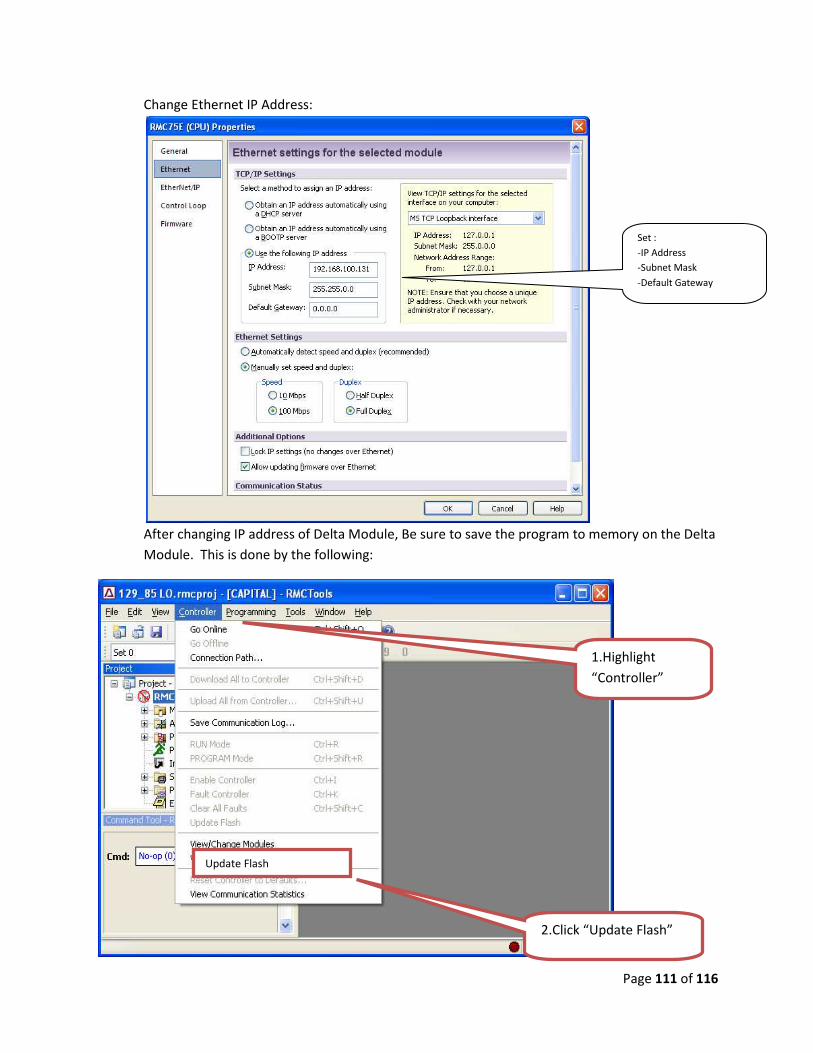
Page 111 of 116
Change Ethernet IP Address:
After changing IP address of Delta Module, Be sure to save the program to memory on the Delta
Module. This is done by the following:
Set :
-IP Address
-Subnet Mask
-Default Gateway
Update Flash
1.Highlight
“Controller”
2.Click “Update Flash”

Page 112 of 116
The following is the procedure to down load the application program to the DELTA Module:
Start RMC Tools Software to Open and Download an application Program.
• From START Menu�PROGRAMS �RMC TOOLS.
• This starts the Delta Software. The window below will appear.
• Open UpCar or LoCar file. File is a .rmcproj file extension. Copy RMC projects to
RMC Tools Directory.
1.Highlight “file”
2.Click “Open”
1.choose file
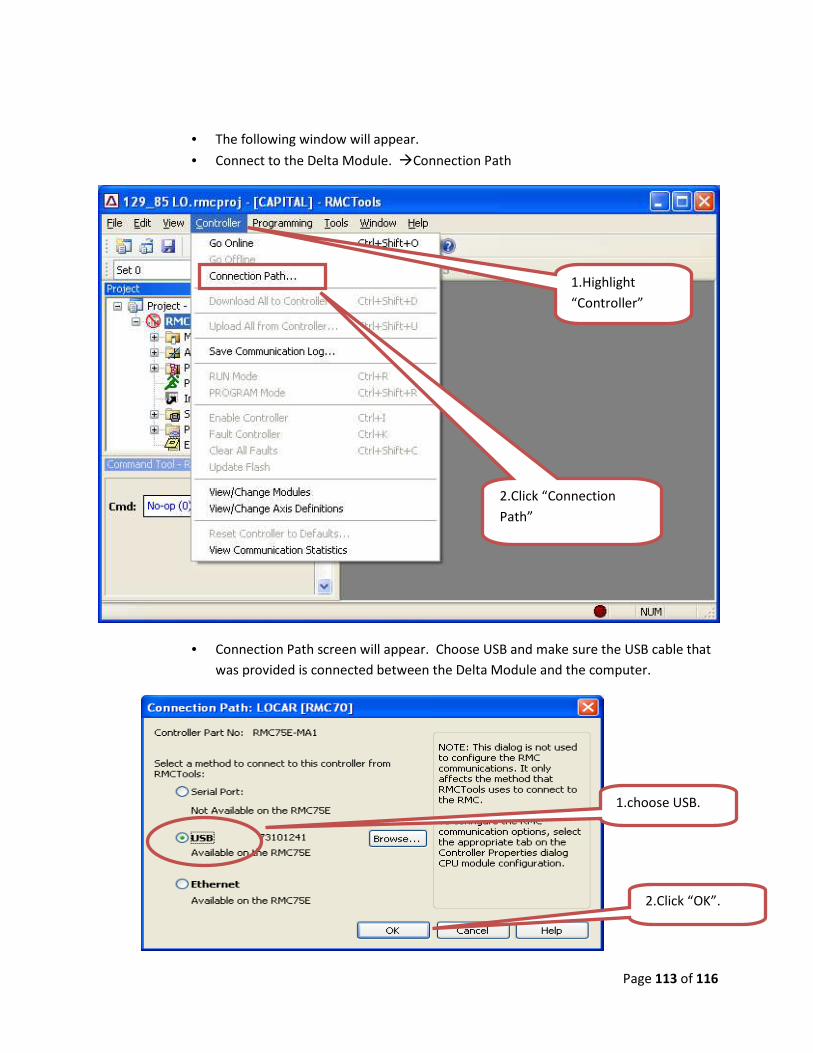
Page 113 of 116
• The following window will appear.
• Connect to the Delta Module. �Connection Path
• Connection Path screen will appear. Choose USB and make sure the USB cable that
was provided is connected between the Delta Module and the computer.
1.Highlight
“Controller”
2.Click “Connection
Path”
1.choose USB.
2.Click “OK”.

Page 114 of 116
• Once Connection to the Delta module has been established. Download the LoCar or
UpCar program to the module.
• After a successful download of the program to the Delta Module, Be sure to save
the program to memory on the Delta Module. This is done by the following:
Download All to Controller
After the down load ensure that
there are NO FAULTS on the
Module. RED LED indicates a
FAULT.
1.Highlight
“Controller”
2.Click “Download All to
Controller”

Page 115 of 116
• Disconnect USB communication cables from the Delta Module, the Set-up and
configuration of the module is complete.
Update Flash
1.Highlight
“Controller”
2.Click “Update Flash”

Page 116 of 116
END