TR 125 937 - V4.1.0 - Universal Mobile Telecommunications ... · 6 Iub/Iur aspects of physical...
33
ETSI TR 125 937 V4.1.0 (2001-09) Technical Report Universal Mobile Telecommunications System (UMTS); Low chip rate TDD Iub/Iur protocol aspects (3GPP TR 25.937 version 4.1.0 Release 4)
Transcript of TR 125 937 - V4.1.0 - Universal Mobile Telecommunications ... · 6 Iub/Iur aspects of physical...

ETSI TR 125 937 V4.1.0 (2001-09)
Technical Report
Universal Mobile Telecommunications System (UMTS);Low chip rate TDD Iub/Iur protocol aspects
(3GPP TR 25.937 version 4.1.0 Release 4)

ETSI
ETSI TR 125 937 V4.1.0 (2001-09) 13GPP TR 25.937 version 4.1.0 Release 4
Reference RTR/TSGR-0325937Uv4R1
Keywords UMTS
ETSI
650 Route des Lucioles F-06921 Sophia Antipolis Cedex - FRANCE
Tel.: +33 4 92 94 42 00 Fax: +33 4 93 65 47 16
Siret N° 348 623 562 00017 - NAF 742 C
Association à but non lucratif enregistrée à la Sous-Préfecture de Grasse (06) N° 7803/88
Important notice
Individual copies of the present document can be downloaded from: http://www.etsi.org
The present document may be made available in more than one electronic version or in print. In any case of existing or perceived difference in contents between such versions, the reference version is the Portable Document Format (PDF).
In case of dispute, the reference shall be the printing on ETSI printers of the PDF version kept on a specific network drive within ETSI Secretariat.
Users of the present document should be aware that the document may be subject to revision or change of status. Information on the current status of this and other ETSI documents is available at
http://portal.etsi.org/tb/status/status.asp
If you find errors in the present document, send your comment to: [email protected]
Copyright Notification
No part may be reproduced except as authorized by written permission. The copyright and the foregoing restriction extend to reproduction in all media.
© European Telecommunications Standards Institute 2001.
All rights reserved.

ETSI
ETSI TR 125 937 V4.1.0 (2001-09) 23GPP TR 25.937 version 4.1.0 Release 4
Intellectual Property Rights IPRs essential or potentially essential to the present document may have been declared to ETSI. The information pertaining to these essential IPRs, if any, is publicly available for ETSI members and non-members, and can be found in ETSI SR 000 314: "Intellectual Property Rights (IPRs); Essential, or potentially Essential, IPRs notified to ETSI in respect of ETSI standards", which is available from the ETSI Secretariat. Latest updates are available on the ETSI Web server (http://www.etsi.org/legal/home.htm).
Pursuant to the ETSI IPR Policy, no investigation, including IPR searches, has been carried out by ETSI. No guarantee can be given as to the existence of other IPRs not referenced in ETSI SR 000 314 (or the updates on the ETSI Web server) which are, or may be, or may become, essential to the present document.
Foreword This Technical Report (TR) has been produced by ETSI 3rd Generation Partnership Project (3GPP).
The present document may refer to technical specifications or reports using their 3GPP identities, UMTS identities or GSM identities. These should be interpreted as being references to the corresponding ETSI deliverables.
The cross reference between GSM, UMTS, 3GPP and ETSI identities can be found under www.etsi.org/key .

ETSI
ETSI TR 125 937 V4.1.0 (2001-09) 33GPP TR 25.937 version 4.1.0 Release 4
Contents
Intellectual Property Rights ................................................................................................................................2
Foreword.............................................................................................................................................................2
Foreword.............................................................................................................................................................5
1 Scope ........................................................................................................................................................6
2 References ................................................................................................................................................6
3 Definitions, symbols and abbreviations ...................................................................................................7 3.1 Definitions..........................................................................................................................................................7 3.2 Symbols..............................................................................................................................................................7 3.3 Abbreviations .....................................................................................................................................................7
4 Overview of the TDD low chip rate option..............................................................................................8 4.1 Physical layer .....................................................................................................................................................8 4.1.1 General..........................................................................................................................................................8 4.1.2 Frame structure .............................................................................................................................................9 4.1.3 Burst Types.................................................................................................................................................10 4.2 Transport Channel and higher layer differences compared to TDD-high ........................................................11 4.3 Other key features of low-chip-rate TDD.........................................................................................................11
5 Iub/Iur aspects of Low chip rate TDD radio frame structure .................................................................11 5.1 Introduction ......................................................................................................................................................11 5.2 Requirements....................................................................................................................................................11 5.3 Study areas .......................................................................................................................................................12 5.4 Agreements and associated contributions.........................................................................................................12 5.5 Specification impact and associated Change Requests.....................................................................................12 5.6 Open issues.......................................................................................................................................................13
6 Iub/Iur aspects of physical channel types...............................................................................................13 6.1 Introduction ......................................................................................................................................................13 6.1.1 General........................................................................................................................................................13 6.1.2 DwPCH.......................................................................................................................................................13 6.1.3 UpPCH........................................................................................................................................................13 6.1.4 FPACH .......................................................................................................................................................13 6.1.5 PRACH.......................................................................................................................................................13 6.2 Requirements....................................................................................................................................................14 6.3 Study areas .......................................................................................................................................................14 6.4 Agreements and associated contributions.........................................................................................................14 6.4.1 TSTD Transmission....................................................................................................................................14 6.4.2 Tx Diversity and Beamforming ..................................................................................................................15 6.4.3 Signaling support for Downlink Tx Diversity ............................................................................................15 6.5 Specification impact and associated Change Requests.....................................................................................15 6.5.1 Impact on TS 25.433 (NBAP) ....................................................................................................................15 6.5.2 Impact on TS 25.430...................................................................................................................................18 6.6 Open issues.......................................................................................................................................................19
7 Iub/Iur aspects of transport channel features..........................................................................................19 7.1 Introduction ......................................................................................................................................................19 7.1.1 General........................................................................................................................................................19 7.1.2 Types of Transport Channels ......................................................................................................................19 7.1.3 System information broadcast.....................................................................................................................20 7.1.4 Usage of RACH..........................................................................................................................................20 7.1.5 Common downlink channels.......................................................................................................................21 7.2 Requirements....................................................................................................................................................21 7.3 Study areas .......................................................................................................................................................21 7.4 Agreements and associated contributions.........................................................................................................21 7.5 Specification impact and associated Change Requests.....................................................................................21
ETSI
ETSI TR 125 937 V4.1.0 (2001-09) 43GPP TR 25.937 version 4.1.0 Release 4
7.6 Open issues.......................................................................................................................................................21
8 Iub/Iur aspects of Uplink synchronisation..............................................................................................21 8.1 Introduction ......................................................................................................................................................21 8.1.1 The establishment of uplink synchronization .............................................................................................22 8.1.1.1 Preparation of uplink synchronization by downlink synchronization ...................................................22 8.1.1.2 Establishment uplink synchronization...................................................................................................22 8.1.2 Maintenance of uplink synchronisation ......................................................................................................22 8.2 Requirements....................................................................................................................................................22 8.3 Study areas .......................................................................................................................................................22 8.4 Agreements and associated contributions.........................................................................................................23 8.5 Specification impact and associated Change Requests.....................................................................................23 8.5.1 Impact on TS 25.401...................................................................................................................................23 8.5.2 Impact on TS 25.402...................................................................................................................................23 8.5.3 Impact on TS 25.425...................................................................................................................................24 8.5.4 Impact on TS 25.427...................................................................................................................................25 8.5.5 Impact on TS 25.435...................................................................................................................................25 8.5.6 Impact on other WG3 Specifications and TRs............................................................................................26 8.6 Open issues.......................................................................................................................................................26
9 Iub/Iur aspects of Measurements............................................................................................................26 9.1 Introduction ......................................................................................................................................................26 9.2 Requirements....................................................................................................................................................27 9.3 Study areas .......................................................................................................................................................27 9.3.1 Propagation delay measurement .................................................................................................................27 9.4 Agreements and associated contributions.........................................................................................................28 9.5 Specification impact and associated Change Requests.....................................................................................28 9.6 Open issues.......................................................................................................................................................28
10 Information elements for 1.28Mcps TDD..............................................................................................28 10.1 Discussion on physical channel parameter for 1.28Mcps.................................................................................28 10.2 Information elements for low chip rate TDD ...................................................................................................29 10.2.1 Time Slot LCR............................................................................................................................................29 10.2.2 Midamble shift LCR ...................................................................................................................................29 10.2.3 TDD Channelisation Code LCR .................................................................................................................29
11 Project Plan ............................................................................................................................................30 11.1 General .............................................................................................................................................................30
Annex A: Change history...............................................................................................................................31
History ..............................................................................................................................................................32
ETSI
ETSI TR 125 937 V4.1.0 (2001-09) 53GPP TR 25.937 version 4.1.0 Release 4
Foreword This Technical Specification has been produced by the 3rd Generation Partnership Project (3GPP).
The contents of the present document are subject to continuing work within the TSG and may change following formal TSG approval. Should the TSG modify the contents of the present document, it will be re-released by the TSG with an identifying change of release date and an increase in version number as follows:
Version x.y.z
where:
x the first digit:
1 presented to TSG for information;
2 presented to TSG for approval;
3 or greater indicates TSG approved document under change control.
y the second digit is incremented for all changes of substance, i.e. technical enhancements, corrections, updates, etc.
z the third digit is incremented when editorial only changes have been incorporated in the document.
ETSI
ETSI TR 125 937 V4.1.0 (2001-09) 63GPP TR 25.937 version 4.1.0 Release 4
1 Scope The work item "Low chip rate TDD Iub/Iur protocol aspects" is a Building Block which has been agreed at TSG RAN#8 as described in contribution [1]. Its parent feature is "Low chip rate TDD" which has been agreed at TSG-RAN#6 and updated at RAN#7. The purpose of the work item "Low chip rate TDD Iub/Iur protocol aspects" is to update the Iub/Iur interface protocol specifications and related overview specifications in RAN WG3 in support of the several aspects of the feature "Low chip rate TDD".
The purpose of the present document is to help the TSG RAN WG3 group to specify the changes to existing specifications, needed for the introduction of the low chip rate TDD option in the UTRAN for Rel.4. It is intended to gather all information in order to trace the history and the status of the Work Task in RAN WG3. It is not intended to replace contributions and Change Requests, but only to list conclusions and make reference to agreed contributions and CRs. When solutions are sufficiently stable, the CRs can be issued.
It describes agreed requirements related to the Work Task, and split the Work Task into "Study Areas" in order to group contributions in a consistent way.
It identifies the affected specifications with related Change Requests.
It also describes the schedule of the Work Task.
The present document is a "living" document, i.e. it is permanently updated and presented to all TSG-RAN meetings.
2 References The following documents contain provisions which, through reference in this text, constitute provisions of the present document.
• References are either specific (identified by date of publication, edition number, version number, etc.) or non-specific.
• For a specific reference, subsequent revisions do not apply.
• For a non-specific reference, the latest version applies. In the case of a reference to a 3GPP document (including a GSM document), a non-specific reference implicitly refers to the latest version of that document in the same Release as the present document.
[1] RP-(00)0316rev, Low chip rate TDD Iub/Iur protocol aspects, Work Item Description
[2] void.
[3] 3GPP TR 25.928: "1.28 Mcps functionality for UTRA TDD Physical Layer".
[4] 3GPP TR 25.834: "UTRA TDD low chip rate option; Radio protocol aspects".
[5] 3GPP TS 25.302: "Services provided by the physical layer".
[6] 3GPP TS 25.420: "UTRAN Iur Interface: General Aspects and Principles".
[7] 3GPP TS 25.430 "UTRAN Iub Interface: General Aspects and Principles".
[8] 3GPP TS 25.401: "UTRAN Overall Description".
[9] 3GPP TS 25.423: "UTRAN Iur interface RNSAP signalling".
[10] 3GPP TS 25.425: "UTRAN Iur interface user plane protocols for CCH data streams".
[11] 3GPP TS 25.427: "UTRAN Iur and Iub interface user plane protocols for DCH data streams".
[12] 3GPP TS 25.433: "UTRAN Iub interface NBAP signalling".
[13] 3GPP TS 25.435: "UTRAN Iub interface user plane protocols for CCH data streams".

ETSI
ETSI TR 125 937 V4.1.0 (2001-09) 73GPP TR 25.937 version 4.1.0 Release 4
[14] 3GPP TR 25.990: "Vocabulary for the UTRAN".
[15] 3GPP TS 25.402: "Synchronisation in UTRAN, stage 2".
[16] 3GPP TR 25.921: "Guidelines and Principles for protocol description and error handling".
3 Definitions, symbols and abbreviations
3.1 Definitions For the purposes of the present document, the terms and definitions given in [14] apply. In addition, the following terms are used, as already introduced in [3] and [4]:
1.28 Mcps TDD The low chip rate option of TDD
3.84 Mcps TDD The high chip rate option of TDD
3.2 Symbols Void.
3.3 Abbreviations For the purposes of the present document, the following abbreviations apply:
ASC Access Service Class BCCH Broadcast Control Channel BCH Broadcast Channel BMC Broadcast/Multicast Control C- Control- CCCH Common Control Channel CCH Control Channel CCTrCH Coded Composite Transport Channel CN Core Network CRC Cyclic Redundancy Check CTCH Common Traffic Channel DC Dedicated Control (SAP) DCA Dynamic Channel Allocation DCCH Dedicated Control Channel DCH Dedicated Channel DL Downlink DRNC Drift Radio Network Controller DSCH Downlink Shared Channel DTCH Dedicated Traffic Channel DwPCH Downlink Pilot Channel FACH Forward Link Access Channel FDD Frequency Division Duplex FPACH Fast Physical Access Channel GC General Control (SAP) GP Guard Period HO Handover ITU International Telecommunication Union kbps kilo-bits per second L1 Layer 1 (physical layer) L2 Layer 2 (data link layer) L3 Layer 3 (network layer) LCR Low Chip Rate MAC Medium Access Control

ETSI
ETSI TR 125 937 V4.1.0 (2001-09) 83GPP TR 25.937 version 4.1.0 Release 4
Nt Notification (SAP) PCCH Paging Control Channel P-CCPCH Primary Common Control Physical Channel PCH Paging Channel PDCP Packet Data Convergence Protocol PDSCH Physical Downlink Shared Channel PDU Protocol Data Unit PHY Physical layer PhyCH Physical Channels P-RACH Physical Random Access Channel PU Payload Unit PUSCH Physical Uplink Shared Channel RAB Radio Access Bearer RACH Random Access Channel RB Radio Bearer RLC Radio Link Control RNC Radio Network Controller RNS Radio Network Subsystem RNTI Radio Network Temporary Identity RRC Radio Resource Control Rx Receive SAP Service Access Point SCH Synchronization Channel SDU Service Data Unit SHCCH Shared Channel Control Channel SIR Signal to Interference Ratio SRNC Serving Radio Network Controller SRNS Serving Radio Network Subsystem TCH Traffic Channel TDD Time Division Duplex TFCI Transport Format Combination Indicator TFI Transport Format Indicator TPC Transmit Power Control TS Technical Specification TS Timeslot Tx Transmit U- User- UE User Equipment UL Uplink UMTS Universal Mobile Telecommunications System UpPCH Uplink Pilot Channel URA UTRAN Registration Area USCH Uplink Shared Channel UTRA UMTS Terrestrial Radio Access UTRAN UMTS Terrestrial Radio Access Network
4 Overview of the TDD low chip rate option
4.1 Physical layer
4.1.1 General
This subclause contains the basic information about frame and burst structure of the physical layer of the TDD low chip rate option. In particular, the differences to the wideband TDD option (3.84 Mcps) are highlighted. More information on the physical layer characteristics of TDD low chip rate option can be found in [3].
The physical layer differences compared to wideband TDD are:

ETSI
ETSI TR 125 937 V4.1.0 (2001-09) 93GPP TR 25.937 version 4.1.0 Release 4
- Chiprate: 1.28 Mcps;
- Frame structure: within a 10 msec frame, there are two sub-frames of 5 msec each; 7 time slots per sub-frame;
- More rigid switching point rule (TS0 is always downlink, TS1 is always uplink);
- Special guard period between TS0 and TS1;
- Special "pilot channels" DwPCH, UpPCH between TS0 and TS1;
- Fast Physical Access Channel (FPACH) for access request acknowledgement;
- Just one burst type (in the normal time slots);
- No physical synchronisation channel SCH;
- Uplink synchronisation is performed at Layer 1 for PRACH and uplink DPCH.
The main reason for these differences compared to wideband TDD are to meet the requirements for:
- Increased range (up to 11 km) without restriction on the time slot allocation;
- Fast uplink synchronisation on uplink physical channels, also on PRACH, for increased capacity;
- Optional support of smart antennas (beamforming).
4.1.2 Frame structure
For low chip rate option, the frame length is 10ms and the 10ms frame is divided into 2 sub-frames of 5ms. The frame structure for each sub-frame in the 10ms frame length is the same. The frame structure for each sub-frame is shown in Figure 1.
UpPCH
(160chips
Subframe 5ms (6400chip)
Ts0 Ts1 1.28Mchip/s
Ts4 Ts2 Ts3 Ts5 Ts6
DwPCH
(96chips) GP (96chips)
Switching Point
Switching Point
Figure 1: Structure of the sub-frame for TDD low chip rate option
Tsn (n from 0 to 6): the nth normal time slot, 864 chips duration.
DwPCH: downlink pilot channel, 96 chips duration.
UpPCH: uplink pilot channel, 160 chips duration.
GP: main guard period for TDD operation, 96 chips duration.
In Figure 1, the total number of normal traffic time slots for uplink and downlink is 7, and the length for each normal time slot is 864 chips duration. Among the 7 normal traffic time slots, Ts0 is always allocated as downlink while Ts1 is always allocated as uplink. The time slots for the uplink and the downlink are separated by a switching point. Between the downlink time slots and uplink time slots, the special period is the switching point to separate the uplink and downlink. In each sub-frame of 5ms for low chip rate option, there are two switching points (uplink to downlink and vice versa). The proposed frame structure has taken some new technologies into consideration; both the smart antenna (beam forming) technology and the uplink synchronisation will be well supported.
ETSI
ETSI TR 125 937 V4.1.0 (2001-09) 103GPP TR 25.937 version 4.1.0 Release 4
4.1.3 Burst Types
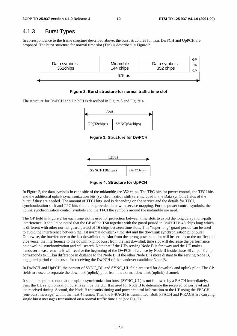
In correspondence to the frame structure described above, the burst structures for Tsn, DwPCH and UpPCH are proposed. The burst structure for normal time slot (Tsn) is described in Figure 2.
Data symbols352chips
Midamble144 chips
Data symbols352 chips
GP
16
CP
675 µs
Figure 2: Burst structure for normal traffic time slot
The structure for DwPCH and UpPCH is described in Figure 3 and Figure 4.
75us
GP(32chips) SYNC(64chips)
Figure 3: Structure for DwPCH
SYNC1(128chips) GP(32chips)
125us
Figure 4: Structure for UpPCH
In Figure 2, the data symbols in each side of the midamble are 352 chips. The TPC bits for power control, the TFCI bits and the additional uplink synchronization bits (synchronization shift) are included in the Data symbols fields of the burst if they are needed. The amount of TFCI bits used is depending on the service and the details for TFCI, synchronization shift and TPC bits should be provided later with service mapping. For the power control symbols, the uplink synchronization control symbols and the TFCI the symbols around the midamble are used.
The GP field in Figure 2 for each time slot is used for protection between time slots to avoid the long delay multi-path interference. It should be noted that the GP of the TS0 together with the guard period in DwPCH is 48 chips long which is different with other normal guard period of 16 chips between time slots. This "super long" guard period can be used to avoid the interference between the last normal downlink time slot and the downlink synchronization pilot burst. Otherwise, the interference to the last downlink time slot from the strong powered pilot will be serious to the traffic; and vice versa, the interference to the downlink pilot burst from the last downlink time slot will decrease the performance on downlink synchronization and cell search. Note that if the UEs serving Node B is far away and the UE makes handover measurements it will receive the beginning of the DwPCH of a close by Node B inside these 48 chip. 48 chip corresponds to 11 km difference in distance to the Node B. If the other Node B is more distant to the serving Node B, big guard period can be used for receiving the DwPCH of the handover candidate Node B.
In DwPCH and UpPCH, the content of SYNC_DL and SYNC_UL field are used for downlink and uplink pilot. The GP fields are used to separate the downlink (uplink) pilot from the normal downlink (uplink) channel.
It should be pointed out that the uplink synchronization burst (SYNC_UL) is not followed by a RACH immediately. First the UL synchronization burst is sent by the UE. It is used for Node B to determine the received power level and the received timing. Second, the Node B transmits timing and power control information to the UE using the FPACH (one burst message) within the next 4 frames. Then the P-RACH is transmitted. Both FPACH and P-RACH are carrying single burst messages transmitted on a normal traffic time slot (see Fig. 2).

ETSI
ETSI TR 125 937 V4.1.0 (2001-09) 113GPP TR 25.937 version 4.1.0 Release 4
4.2 Transport Channel and higher layer differences compared to TDD-high
For details on the higher layers of the radio protocol of the low-chip-rate TDD option see [4].
At Transport Channel level, no significant differences compared to wideband TDD have been identified. The only points to mention are:
The "Rx Timing Deviation" measurement performed by Node B for RACH, uplink DCH, and USCH, may become obsolete since Timing advance (performed for wideband TDD at RRC level) is replaced by Fast Uplink Synchronisation which is a Layer 1 function performed by Node B with minimum higher layer interactions.
DSCH and USCH details may be different.
4.3 Other key features of low-chip-rate TDD Smart antenna. The frame structure of 1.28 Mcps TDD has taken some new technologies into consideration, both the smart antenna (beam forming) technology and the uplink synchronisation will be well supported [4].
5 Iub/Iur aspects of Low chip rate TDD radio frame structure
5.1 Introduction This subclause includes several properties of the radio frames used in low chip rate TDD. On the Iub and Iur interface, this will imply new parameters and information elements in the radio related control plane protocols.
The following impacts have been identified in a Liaison Statement from RAN1 to RAN3 [2].
- Different frame structure than for high chiprate TDD option;
- Different basic midamble sequences, maximum channel impulse response is scalable (W=8, 9, 12, 16, 21, 32, 64), depending on number of users and environment, including the association between midambles and channelisation codes;
- Use of only one burst type for physical channels except special bursts in DwPCH/UpPCH. Because there is only one burst type in low chip rate TDD option, “burst type” defined as a parameter for physical channel is not necessary;
- Support of different timeslot formats due to different number of bits and L1 control signals and midamble length;
- Support of use of 8PSK for special timeslots/all timeslots per cell;
- Beacon function is provided by DwPCH and P-CCPCH.
5.2 Requirements In view of the Iub/Iur aspects, the requirements resulting from the different frame structure of 1.28 Mcps TDD compared to 3.84 Mcps TDD are as follows.
In NBAP and RNSAP messages, the information elements referring to time slot information, burst types, and common physical channels will have to be updated to cover both TDD chip rate options. If necessary, new IEs dedicated to 1.28 Mcps TDD will have to be introduced.
These NBAP and RNSAP procotol extensions towards Rel.4 must be done in a backward compatible way, which means, among others: A Rel.4 Node B shall be able to understand Rel.99 NBAP messages, and a Rel.99 Node B shall be able to understand and comprehend Rel.4 messages and shall execute the functions provided these are within the scope of the Rel.99 Node B.

ETSI
ETSI TR 125 937 V4.1.0 (2001-09) 123GPP TR 25.937 version 4.1.0 Release 4
The Release 4 versions of NBAP and RNSAP, including the changes required for support of both TDD chip rate options, shall - like the Rel99 versions - meet the principles for protocol description and error handling established in [16].
5.3 Study areas It has been studied how the different time slot structure and burst type can be introduced in RNSAP and NBAP in a way which meets the above mentioned requirements.
In particular, it was studied whether a "CHOICE TDD mode" could be introduced within the existing Timeslot Info IE, to extend this IE to include the parameters of 1.28 Mcps TDD as well. However, it has been found that this would result in a non-backward compatible change to NBAP and RNSAP: A Release 99 Node B would not understand the extended IE even if the IE would only address the 3.84 Mcps TDD option. So it was decided to introduce a new Timeslot Information LCR IE and some related IEs with extension "LCR" (where LCR means "Low Chip Rate"), and to introduce these as optional IEs (although mandatory for 1.28Mcps TDD) in the respective messages, for the sake of backward compatibility to Rel.99, as described below.
5.4 Agreements and associated contributions As a result of the studies, it was agreed to introduce the following new IEs in NBAP and/or RNSAP, in support of the new Frame Structure and radio burst parameters for 1.28Mcps TDD:
Existing IE for 3.84 Mcps TDD New Rel.4 LCR IE for 1.28 Mcps TDD What is the difference of the 1.28Mcps IE compared to 3.84?
Time Slot IE Time Slot LCR IE Range 0..6 rather than 0..14 TDD Channelisation Code IE TDD Channelisation Code LCR IE 8PSK modulation option Midamble Shift and Burst Type IE Midamble Shift LCR IE Midamble not dependent on burst type;
just 1 burst type. DL Timeslot Information IE DL Timeslot Information LCR IE Includes Time Slot LCR IE, Midamble
Shift LCR IE, DL Code Information LCR IE
UL Timeslot Information IE UL Timeslot Information LCR IE Includes Time Slot LCR IE, Midamble Shift LCR IE, UL Code Information LCR IE
TDD DL Code Information IE TDD DL Code Information LCR IE Includes TDD Channelisation Code LCR IE
TDD UL Code Information IE TDD UL Code Information LCR IE Includes TDD Channelisation Code LCR IE
UL Time Slot ISCP Info IE UL Time Slot ISCP Info LCR IE Includes Time Slot LCR IE DL Time Slot ISCP Info IE DL Time Slot ISCP Info LCR IE Includes Time Slot LCR IE Neighbouring TDD Cell Information IE Neighbouring TDD Cell Information
LCR IE Includes Time Slot LCR IE
For the details of the definition of these IEs, see the proposed Change Requests to NBAP and RNSAP for introducing the 1.28 Mcps TDD option.
5.5 Specification impact and associated Change Requests These Iub/Iur protocol aspects have impacts on the following Specifications:
[12] (NBAP), [9] (RNSAP).
In addition, the UpPCH and the DwPCH which use the special, short time slots between TS0 and TS1, are visible in the Node B resources model in [7].
The other RAN WG3 Technical Specifications are not affected by the new radio frame structure of 1.28Mcps TDD.
ETSI
ETSI TR 125 937 V4.1.0 (2001-09) 133GPP TR 25.937 version 4.1.0 Release 4
5.6 Open issues None.
6 Iub/Iur aspects of physical channel types
6.1 Introduction
6.1.1 General
In addition to the physical channels defined for UTRA TDD, three physical channels are added to support low chip rate TDD option, they are: DwPCH (Downlink Pilot Channel), UpPCH (Uplink Pilot Channel) and FPACH (Fast Physical Access CHannel). Besides, two physical channels, Primary SCH and Secondary SCH, are not needed in low chip rate TDD option.
Because there is only one burst type in low chip rate TDD option, “burst type” defined as a parameter for physical channel is not necessary
Shared channels, PUSCH and PDSCH, will be supported by TDD low chip rate option, but details are ffs [4].
The parameters of the added physical channels and of the modified PRACH, as far as the Iub interface protocols are concerned, are described in the following.
6.1.2 DwPCH
- Tx diversity mode (TSTD indicator);
- SYNC_DL code ID;
- DwPCH power.
6.1.3 UpPCH
- SYNC_UL code ID. The Node B derives this parameter from the channelisation code parameters of FPACH and PRACH in a standardised way [3], therefore the UpPCH is not explicitly configured in the Node B.
6.1.4 FPACH
- Channelisation code;
- Timeslot;
- Midamble shift;
- Max FPACH power.
6.1.5 PRACH
- Timeslot;
- Spreading Codes;
- Midamble Shift.

ETSI
ETSI TR 125 937 V4.1.0 (2001-09) 143GPP TR 25.937 version 4.1.0 Release 4
6.2 Requirements In view of the Iub/Iur aspects, the requirements resulting from the specific physical channel types of 1.28 Mcps TDD compared to 3.84 Mcps TDD are as follows.
In NBAP and RNSAP messages, the information elements referring to common physical channels will have to be updated to cover both TDD chip rate options. For FPACH and DwPCH, new IEs will have to be introduced.
These NBAP and RNSAP procotol extensions towards Rel.4 must be done in a backward compatible way.
The Release 4 versions of NBAP and RNSAP, including the changes required for support of both TDD chip rate options, shall - like the Rel99 versions - meet the principles for protocol description and error handling established in [16].
6.3 Study areas It has been studied how the changes can be introduced in RNSAP and NBAP in a way which meets the above mentioned requirements.
It was decided to introduce new LCR specific IEs, and to introduce these as optional IEs (although mandatory for 1.28Mcps TDD) in the respective messages, for the sake of backward compatibility to Rel.99.
At the same time, the IEs which are specific for 3.84 Mcps TDD and hence not applicable for 1.28 Mcps TDD, shall be made optional, in the Tabular messages and in ASN.1, to allow to omit these in 1.28 Mcps TDD related messages. This is possible in a backward compatible way, provided that these IEs have an assigned criticality in the Release 99 versions of NBAP and RNSAP. In case these IEs are in fact mandatory for either of the TDD chiprate options, it shall be noted in the "Semantics description" in the tabular format, and in ASN.1, and in the procedure text, that the presence of these IEs is conditional on the choice of the TDD chiprate option.
6.4 Agreements and associated contributions
6.4.1 TSTD Transmission
In the TSTD scheme for 1.28 Mcps TDD, two spatially separated antennas are alternately used at the base station to transmit each consecutive sub-frame of the downlink physical channels. The TSTD scheme takes advantage of the frame structure of the 1.28Mcps UTRA TDD, where the frame structure makes TSTD transmission possible with a single power amplifier.
A summary of the TSTD scheme is as follows:
- The TSTD scheme takes advantage of the sub-frame structure of 1.28Mcps TDD mode.
- Negligible additional hardware cost for base station (no additional power amplifier).
- There is little impact on UE receiver structure.
- TSTD requires minimal higher layer signalling. The higher layer only need to inform the UE that TSTD scheme is used so that UE can use appropriate power control algorithm.
Sub-frame (5ms)Sub-frame (5ms)
ANT 1
ANT 2
12.5 micro sec 12.5 micro sec
Figure 6.1: TSTD switching pattern utilizing sub-frame structure in down link

ETSI
ETSI TR 125 937 V4.1.0 (2001-09) 153GPP TR 25.937 version 4.1.0 Release 4
6.4.2 Tx Diversity and Beamforming
Depending on the capability of the base station and the characteristics of the physical channels, many different combinations of TSTD, STTD, and beamforming are possible. For DwPCH, STTD cannot be used due to its nature. For P-CCPCH, both of the STTD and TSTD can be used but beamforming cannot be used because P-CCPCH carries the broadcast channel BCH. On the other hand, beamforming as well as Tx diversity schemes such as STTD or TSTD can be used for DPCH.
The different transmit diversity schemes for different downlink physical channel types in 1.28Mcps TDD are described in [3].
6.4.3 Signaling support for Downlink Tx Diversity
For 3.84 Mcps TDD, CRNC determines whether a cell apply downlink Tx diversity to DCH or not and Block STTD to PCCPCH when the sell is set up. For 1.28 Mcps TDD, CRNC may determine that a cell apply TSTD to PCCPCH and DwPCH. The corresponding information should be included in CELL SETUP REQUST message to support the downlink Tx diversity schemes for 1.28 Mcps TDD. For each Radio Link, CRNC may determine that TSTD is applied to the Radio Link. The corresponding information should be included in RADIO LINK SETUP/ADDITION RESPONSE RNSAP message and RADIO LINK SETUP/ADDITION REQUEST NBAP message.
The needed new IE in CELL SETUP REQUEST message for 1.28 Mcps TDD is as follows:
- TSTD Indicator IE for PCCPCH;
- TSTD Indicator IE on DwPCH.
The needed new IE in RADIO LINK SETUP/ADDITION RESPONSE RNSAP message and RADIO LINK SETUP/ADDITION REQUEST NBAP message for 1.28 Mcps TDD is as follows:
- TSTD Indicator IE for Radio Link.
6.5 Specification impact and associated Change Requests These Iub/Iur protocol aspects have effects on the following specifications:
25.430 [7], RNSAP [9], NBAP [12], 25.435 [13].
6.5.1 Impact on TS 25.433 (NBAP)
In addition to the new IEs listed in subclause 5.4 related to the Frame Structure, the following IEs need to be defined:
Existing IE for 3.84 Mcps TDD New Rel.4 LCR IE for 1.28 Mcps TDD What is the difference of the 1.28Mcps IE compared to 3.84?
- Max FPACH Power IE FPACH newly introduced. - DwPCH Power IE DwPCH newly introduced. - SYNC_DL Code ID IE DwPCH newly introduced.
In addition, new IEs are required in support of TSTD for 1.28Mcps TDD.
The needed new IE in CELL SETUP REQUEST message for 1.28 Mcps TDD is as follows:
- TSTD Indicator IE for PCCPCH;
- TSTD Indicator IE on DwPCH.
The needed new IE in RADIO LINK SETUP/ADDITION RESPONSE RNSAP message and RADIO LINK SETUP/ADDITION REQUEST NBAP message for 1.28 Mcps TDD is as follows:
- STD Indicator IE for Radio Link.

ETSI
ETSI TR 125 937 V4.1.0 (2001-09) 163GPP TR 25.937 version 4.1.0 Release 4
The following examples show how the CELL SETUP REQUEST message for TDD cells in NBAP could be changed for Release 4, to include the Information Elements of the low-chip-rate TDD option in a backward compatible way.
Example: CELL SETUP REQUEST (TDD Message, TS25.433) with extensions for the low chip rate TDD option
(TS25.433 .1.24.2 TDD Message).

ETSI
ETSI TR 125 937 V4.1.0 (2001-09) 173GPP TR 25.937 version 4.1.0 Release 4
IE/Group Name Presence Range IE type and reference
Semantics description
Criticality Assigned Criticality
Message discriminator M 9.2.1.45 – Message Type M 9.2.1.46 YES reject Transaction ID M 9.2.1.62 – Local Cell Id M 9.2.1.38 YES reject C-Id M 9.2.1.9 YES reject Configuration Generation Id M 9.2.1.16 YES reject UARFCN M 9.2.1.65 Corresponds
to Nt [15] YES reject
Cell Parameter ID M 9.2.3.4 YES reject Maximum Transmission Power
M 9.2.1.40 YES reject
Transmission Diversity Applied
M 9.2.3.26 On DCHs YES reject
Sync Case M 9.2.3.18 YES reject Synchronisation Configuration
1 YES reject
>N_INSYNC_IND M 9.2.1.47A – >N_OUTSYNC_IND M 9.2.1.47B –
>T_RLFAILURE M 9.2.1.56A – DPCH Constant Value M Constant
Value YES reject
PUSCH Constant Value M Constant Value
YES reject
PRACH Constant Value M Constant Value
YES reject
SCH Information O 1 Mandatory For 3.84Mcps TDD only
YES reject
>Common physical channel ID
M 9.2.1.13 –
>CHOICE Sync Case >>Case 1 YES reject
>>>Time Slot M 9.2.3.23 – >>Case 2 YES reject
>>>SCH Time Slot M 9.2.3.17 – >SCH Power M DL Power
9.2.1.21 –
>TSTD Indicator M 9.2.1.64 – PCCPCH Information O 1 Mandatory
For 3.84Mcps TDD only
YES reject
>Common physical channel ID
M 9.2.1.13 –
>TDD Physical Channel Offset
M 9.2.3.20 ‘Offset ‘= 0 for low chip rate TDD
–
>Repetition Period M 9.2.3.16 – >Repetition Length M 9.2.3.15 – >PCCPCH Power M 9.2.3.9 – >Block STTD Indicator M 9.2.3.1 – >TSTD Indicator O 9.2.1.64 For low chip
rate TDD YES reject
Time Slot Configuration O 1 .. 15 Mandatory For 3.84Mcps TDD only
GLOBAL reject
>Time Slot M 9.2.3.23 – >Time Slot Status M 9.2.3.25 – >Time Slot Direction M 9.2.3.24 –
Time Slot Configuration LCR
O 1 .. 7 Mandatory For 1.28Mcps TDD only
GLOBAL Reject
>Time Slot LCR M 9.2.3.x – >Time Slot Status M 9.2.3.25 –
ETSI
ETSI TR 125 937 V4.1.0 (2001-09) 183GPP TR 25.937 version 4.1.0 Release 4
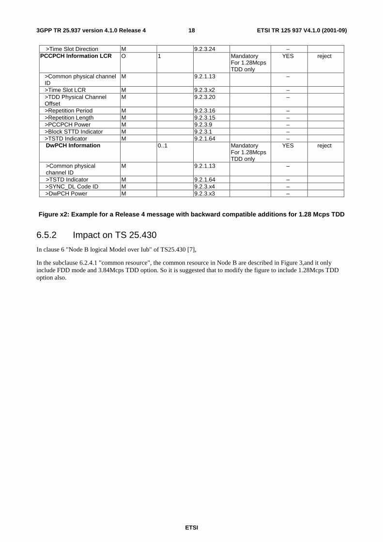
>Time Slot Direction M 9.2.3.24 – PCCPCH Information LCR O 1 Mandatory
For 1.28Mcps TDD only
YES reject
>Common physical channel ID
M 9.2.1.13 –
>Time Slot LCR M 9.2.3.x2 – >TDD Physical Channel Offset
M 9.2.3.20 –
>Repetition Period M 9.2.3.16 – >Repetition Length M 9.2.3.15 – >PCCPCH Power M 9.2.3.9 – >Block STTD Indicator M 9.2.3.1 – >TSTD Indicator M 9.2.1.64 – DwPCH Information 0..1 Mandatory
For 1.28Mcps TDD only
YES reject
>Common physical channel ID
M 9.2.1.13 –
>TSTD Indicator M 9.2.1.64 – >SYNC_DL Code ID M 9.2.3.x4 – >DwPCH Power M 9.2.3.x3 –
Figure x2: Example for a Release 4 message with backward compatible additions for 1.28 Mcps TDD
6.5.2 Impact on TS 25.430
In clause 6 "Node B logical Model over Iub" of TS25.430 [7],
In the subclause 6.2.4.1 "common resource", the common resource in Node B are described in Figure 3,and it only include FDD mode and 3.84Mcps TDD option. So it is suggested that to modify the figure to include 1.28Mcps TDD option also.

ETSI
ETSI TR 125 937 V4.1.0 (2001-09) 193GPP TR 25.937 version 4.1.0 Release 4
The following figure is recommended:
Cell
PCPICHCPCId
SCH1CPCId
SCH2CPCId
PCCPCHCPCId
SCPICHCPCId
SCCPCHCPCId
AICHCPCId
PRACHCPCId
BCHCTCId
PCHCTCId
FACHCTCId
RACHCTCId
1
11
1
1
1 1
10- m 0-k0-i 0-k
0-1 0-n
CPCId = Common Physical Channel IdentifierCTCId = Common Transport Channel Identifier[TDD - The number of PICH = the number of PCH][FDD - The number of AICH = the number of
PRACH][TDD – PCH and FACHs can be mapped on one or
more SCCPCH]
SCHCPCId
1
[FDD Only] [3.84McpsTDD Only]
[FDD Only]
PICHCPCId
[FDD 1][TDD ≥≥≥≥ 1]
[FDD 0-i][TDD 0-1]
1[FDD 1][TDD ≥≥≥≥ 1]
PCPCHCPCId
0-j
CPCHCTCId
[FDD Only]
CD/CA-ICHCPCId
AP-AICHCSICHCPCId
0-q 0-q
1 - p1
UpPCH DwPCHCPCId
FPACHCPCId
1 1 0-r
[1.28McpsTDD Only]
Cell-Id
Figure X: Common resources in a Node B that are managed by the CRNC
6.6 Open issues None.
7 Iub/Iur aspects of transport channel features
7.1 Introduction
7.1.1 General
The transport channel concept for UTRA TDD low chip rate option is the same as for UTRA TDD 3.84 Mcps as defined in [5]. Some differences exist with respect to the features of some of the transport channels.
7.1.2 Types of Transport Channels
A general classification of transport channels is into two groups:
ETSI
ETSI TR 125 937 V4.1.0 (2001-09) 203GPP TR 25.937 version 4.1.0 Release 4
- Common channels; and
- Dedicated channels (where the UEs can be unambiguously identified by the physical channel, i.e. code, frequency and time slot).
Common transport channel types are the same as for UTRA TDD 3.84 Mcps. Details of operation on RACH and FACH are ffs, e.g. power control. RACH and FACH are characterized as follows:
1. Random Access Channel(s) (RACH) characterised by:
- Existence in uplink only;
- Limited data field;
- Collision risk;
- Power control.
2. Forward Access Channel(s) (FACH) characterised by:
- Existence in downlink only;
- Possibility to use beam forming;
- Power control;
- Possibility to change rate fast (each 10ms);
- The details of shared channels USCH and DSCH are ffs.
Dedicated transport channel types are the same as for UTRA TDD 3.84 Mcps. For TDD low chip rate option, DCH has the possibility to use Uplink Synchronisation to maintain timing advance:
1. Dedicated Channel (DCH) characterised by:
- Existing in uplink or downlink;
- Possibility to use beam forming;
- Possibility to change rate fast (each 10ms);
- Fast power control;
- Possibility to use Uplink Synchronisation.
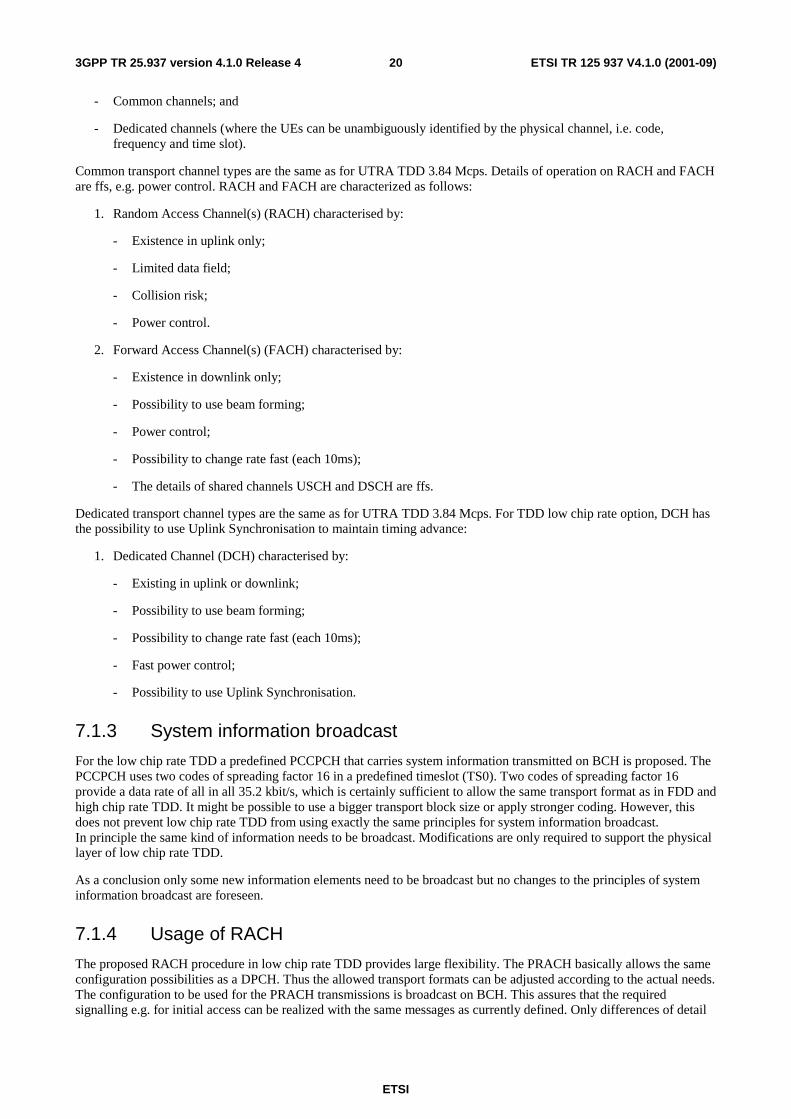
7.1.3 System information broadcast
For the low chip rate TDD a predefined PCCPCH that carries system information transmitted on BCH is proposed. The PCCPCH uses two codes of spreading factor 16 in a predefined timeslot (TS0). Two codes of spreading factor 16 provide a data rate of all in all 35.2 kbit/s, which is certainly sufficient to allow the same transport format as in FDD and high chip rate TDD. It might be possible to use a bigger transport block size or apply stronger coding. However, this does not prevent low chip rate TDD from using exactly the same principles for system information broadcast. In principle the same kind of information needs to be broadcast. Modifications are only required to support the physical layer of low chip rate TDD.
As a conclusion only some new information elements need to be broadcast but no changes to the principles of system information broadcast are foreseen.
7.1.4 Usage of RACH
The proposed RACH procedure in low chip rate TDD provides large flexibility. The PRACH basically allows the same configuration possibilities as a DPCH. Thus the allowed transport formats can be adjusted according to the actual needs. The configuration to be used for the PRACH transmissions is broadcast on BCH. This assures that the required signalling e.g. for initial access can be realized with the same messages as currently defined. Only differences of detail

ETSI
ETSI TR 125 937 V4.1.0 (2001-09) 213GPP TR 25.937 version 4.1.0 Release 4
of the messages requiring the RACH are foreseen. However, the details of the realization of a similar concept for Access Service Classes are currently under further study.
As a conclusion there are no major problems identified that will result in problems of the usage of the principles of the current NBAP/RNSAP protocol.
7.1.5 Common downlink channels
The common channels can also be configured to provide sufficient capacity for the messages that need to be transmitted on common downlink channels. The exact configuration is as in FDD and high chip rate TDD broadcasted on BCH.
BCH is mapped on the P-CCPCH while PCH, PICH and FACH can be time multiplexed on the S-CCPCH. These physical channels are using channelisation codes of SF 16.
7.2 Requirements The Iub/Iur protocols shall support all the above mentioned features with reuse of the existing protocol principles.
7.3 Study areas The study areas related to the Transport Channel differences are the same as for the Physical Channel differences between 1.28Mcps and 3.84Mcps TDD, discussed in subclause 6.3.
7.4 Agreements and associated contributions See the proposed Change Requests.
7.5 Specification impact and associated Change Requests It is expected that this Iub/Iur protocol aspects has impacts on the following Specifications:
RNSAP [9], 25.433 [12].
7.6 Open issues None.
8 Iub/Iur aspects of Uplink synchronisation
8.1 Introduction This aspect includes the following items:
- Special Layer1-Synchronisation Shift (SS) symbols;
- Number of used SS symbols can take 3 values;
- SS-symbols are transmitted once per subframe.
In principle, this feature replaces the “Timing advance” function which is performed by higher layer interaction in 3.84 Mcps TDD.

ETSI
ETSI TR 125 937 V4.1.0 (2001-09) 223GPP TR 25.937 version 4.1.0 Release 4
8.1.1 The establishment of uplink synchronization
8.1.1.1 Preparation of uplink synchronization by downlink synchronization
When a UE is powered on, it first needs to establish the downlink synchronisation with the cell as describe in [3] about cell search procedure. Only after the UE can establish and maintain the downlink synchronisation, it can start the uplink synchronisation procedure.
8.1.1.2 Establishment uplink synchronization
Although the UE can receive the downlink synchronization signal from the Node B, the distance to Node B is still uncertain which would lead unsynchronised uplink transmission. Therefore, the first transmission in uplink direction is performed in a special Channel UpPCH to reduce interference in traffic time-slots.
The timing used for the SYNC_UL burst are set e.g. according to the received power level of DwPCH and/or P-CCPCH.
At the detection of the SYNC_UL sequence in the searching window, the Node B will evaluate the received power levels and timing, and reply by sending the adjustment information to UE to modify its timing and power level for next transmission and for establishment of the uplink synchronisation procedure. Within the next 4 sub-frames, the Node B will send the adjustment information to the UE (in a single subframe message in the FPACH) The uplink synchronisation procedure, normally used for a random access to the system, can also be used for the re-establishment of the uplink synchronisation when uplink is out of synchronisation.
8.1.2 Maintenance of uplink synchronisation
For the maintenance of the uplink synchronization, the midamble field of each uplink burst can be used.
In each uplink time slot the midamble in each UE is different. The Node B can estimate the power level and timing shift by measuring the midamble field of each UE in the same time slot. Then, in the next available downlink time slot, the Node B will signal the Synchronisation Shift (SS) and the Power Control (PC) commands to enable the UE to properly adjust respectively its Tx timing and Tx power level.
These procedures guarantee the reliability of the uplink synchronisation. The uplink synchronization can be checked once per TDD sub-frame. The step size in uplink synchronization is configurable and re-configurable and can be adapted from 1/8 chip to 1 chip duration. The following updates for UL synchronization are possible: 1 step up; 1 step down; no update.
[Explanation difference:]
For high chip rate option, uplink synchronisation is mentioned in 4.3 of TS25.224. But the implementation method is a little different with the low chip rate option. For low chip rate option, the establishment of the UL synchronization is done by using the UpPCH and the FPACH.
It allocates a unique channel UpPCH for UE to establish uplink synchronisation in the access procedure. The benefit of this method is when the UE wants to do random access, the P-RACH will have minimum interference to other traffic channel. Vice versa, it will also reduce the interference from traffic channels to P-RACH.
8.2 Requirements The Iub/Iur protocols shall support the above mentioned features for uplink synchronisation with reuse of the existing protocol principles.
8.3 Study areas The impact of the "uplink synchronisation" feature on the Iub/Iur protocols have been studied. One basic consequence has been identified: Due to this layer-1 function, the "Rx timing deviation" measurement performed by Node B for 3.84 Mcps TDD and reported to CRNC and SRNC, becomes obsolete. Therefore this measurement if deleted both from the Iub and Iur frame protocols for RACH, DCH, and USCH, and from the NBAP measurement procedure.

ETSI
ETSI TR 125 937 V4.1.0 (2001-09) 233GPP TR 25.937 version 4.1.0 Release 4
It has also been studied how this removal of the "Rx Timing Deviation" measurement from NBAP affects the UE positioning methods. The decision was that UE positioning in TDD does not need this measurement; the knowledge about the currently applied timing advance, and hence the signal roundtrip delay, is available in the UE and must be retrieved from the UE on request. This is an RRC procedure for which the Iub/Iur protocols are transparent.
In addition, it has been studied how the requirement for continuous synchronisation of uplink channels in 1.28 Mcps TDD affects the RRM strategies because of the need for downlink commands during uplink transmission. However this issue has no impact on the Iub/Iur protocols.
8.4 Agreements and associated contributions See the proposed Change Requests.
8.5 Specification impact and associated Change Requests It is expected that this Iub/Iur protocol aspects has impacts on the following Specifications:
25.401 [8], RNSAP [9], 25.425 [10], 25.427 [11], NBAP [12], 25.435 [13], 25.402 [15].
8.5.1 Impact on TS 25.401
In clause 6 "UTRAN Architecture" of TS25.401 [8], some details might be added to the third paragraph:
"A Node B can support FDD mode, TDD mode or dual-mode operation. There are two options in TDD mode, 1.28Mcps TDD option and 3.84Mcps TDD option".
In clause 7 "UTRAN functions description" of TS25.401 [8]:
In the subclause 7.2.4.14 "[TDD - Timing Advance]", some details might be added because the function implementation is quite different between 1.28Mcps TDD option and 3.84Mcps:
"This function is used in uplink to align the uplink radio signals from the UE to the UTRAN. In 3.84Mcps TDD option, Timing advance is based on uplink burst timing measurements performed by the Node B L1, and on Timing Advance commands sent downlink to the UE. In 1.28Mcps TDD option, the Timing Advance function can be achieved by uplink synchronization procedure".
In addition, in clause 9 "Synchronisation" of TS25.401 [8], the "uplink synchronisation" function might be added to the list of UTRAN functions related to synchronisation.
8.5.2 Impact on TS 25.402
In clause 4 "Synchronisation Issues" of TS25.402, the issue "uplink synchronization" for 1.28Mcps TDD might be included in the subclause 4.1 "general" of TS25.402:
Different synchronisation issues are identified within UTRAN, i.e.:
- Network Synchronisation;
- Node Synchronisation;
- Transport Channel synchronisation;
- Radio Interface Synchronisation;
- Time Alignment handling;
- Uplink synchronization.
So the Synchronisation Issues Model of Figure 1 in TS25.402 might be changed for including uplink synchronisation. The details are FFS.

ETSI
ETSI TR 125 937 V4.1.0 (2001-09) 243GPP TR 25.937 version 4.1.0 Release 4
It is suggested that add the summary of Uplink synchronization into new subclause 4.X and the details into a new clause X of TS25.402.
Since the Timing Advance function implementation is quite different between 1.28Mcps TDD option and 3.84Mcps, it is suggested for subclause 8.3 "TDD Radio interface Synchronisation", to change the title of subclause 8.3.4 "Timing Advance" to "Timing Advance for 3.84Mcps" and add a new subclause 8.3.X "Uplink synchronization for 1.28Mcps".
8.5.3 Impact on TS 25.425
In principle, the "uplink synchronisation" feature in 1.28Mcps TDD replace or complement the "time advance" function which is performed by higher layer interaction in 3.84Mcps.
In subclause 6.2.1 "RACH/CPCH [FDD] Channels", the RACH/CPCH [FDD] Data Frame structure showed in Figure 9 shall be changed as follows:
Conditional 3.84Mcps TDD
Header CRC
SRNTI
Header
Payload
MAC-c SDU 1
7 0
SRNTI (cont)
FT
SRNTI (cont)
Payload CRC
Payload CRC (cont)
MAC-c/sh SDU 1 (cont)
MAC-c/sh SDU n
MAC-c/sh SDU n (cont)
Spare bits 7-4
Tail
Spare bits 7-4
NumOfSDU
MAC-c/sh SDU Length
MAC-c/sh SDU Length (cont)
Spare bits 3-0
Spare bits 2-0
Propagation Delay Conditional FDD
Spare Extension
Rx Timing Deviation Spare
Received SYNC_UL Timing Deviation Conditional 1.28Mcps TDD
Figure 9: RACH/CPCH [FDD] Data Frame structure and the description shall be changed as follows: "Rx Timing Deviation is a conditional Information Element which is only present when the Cell supporting the RACH Transport Channel is a 3.84Mcps TDD Cell".
Additional description shall be added as follows: "Received SYNC_UL Timing Deviation is a conditional Information Element which is only present when the Cell supporting the RACH Transport Channel is a 1.28Mcps TDD Cell".
ETSI
ETSI TR 125 937 V4.1.0 (2001-09) 253GPP TR 25.937 version 4.1.0 Release 4
8.5.4 Impact on TS 25.427
The same reason as above, the title of subclause 5.6 "Rx timing deviation measurement [TDD]" shall be changed to "Rx timing deviation measurement [3.84Mcps TDD]", because the procedure is applicable in 3.84Mcps TDD option only.
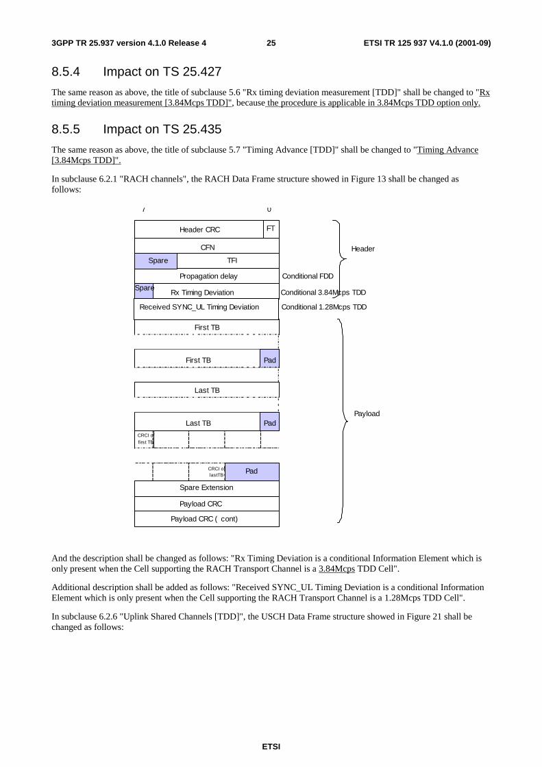
8.5.5 Impact on TS 25.435
The same reason as above, the title of subclause 5.7 "Timing Advance [TDD]" shall be changed to "Timing Advance [3.84Mcps TDD]".
In subclause 6.2.1 "RACH channels", the RACH Data Frame structure showed in Figure 13 shall be changed as follows:
Header CRC
CFN
First TB
CRCI of first TB
Payload
CRCI of lastTB
TFI
FT
Propagation delay
First TB
Pad
Pad
7 0
Payload CRC
Payload CRC ( cont )
Last TB
Last TB
Pad
Conditional FDD
Header
Spare Extension
Spare
Rx Timing Deviation Spare
Received SYNC_UL Timing Deviation Conditional 3.84Mcps TDD
Conditional 1.28Mcps TDD
And the description shall be changed as follows: "Rx Timing Deviation is a conditional Information Element which is only present when the Cell supporting the RACH Transport Channel is a 3.84Mcps TDD Cell".
Additional description shall be added as follows: "Received SYNC_UL Timing Deviation is a conditional Information Element which is only present when the Cell supporting the RACH Transport Channel is a 1.28Mcps TDD Cell".
In subclause 6.2.6 "Uplink Shared Channels [TDD]", the USCH Data Frame structure showed in Figure 21 shall be changed as follows:

ETSI
ETSI TR 125 937 V4.1.0 (2001-09) 263GPP TR 25.937 version 4.1.0 Release 4
Header CRC
CFN
First TB
Header
Payload
TFI
FT
First TB
Pad
7 0
Payload CRC
Payload CRC ( cont )
QE
Last TB
CRCI of first TB
CRCI of lastTB Pad
Spare Extension
Last TB Pad
Spare Condit ional
3.84Mcps TDD Rx Timing Deviation pare
8.5.6 Impact on other WG3 Specifications and TRs
It is expected that the Iub/Iur aspects of uplink synchonisation have an impact also on the Specifications [9] and [12] because it may influence the physical channel handling procedures. In this TR (25.937), these aspects are covered implicitly in clause 6 where the physical channel types are addressed.
8.6 Open issues None.
9 Iub/Iur aspects of Measurements
9.1 Introduction This aspect includes the following bullets:
- Ranges and accuracy have to be adapted for the low chip rate option.
In principle, this issue relates to:
- measurements to be performed by Node B and to be reported to DRNC/SRNC, and
- measurements performed by UE, reported to SRNC or CRNC, and used by SRNC, DRNC or Node B.
Due to the different power control and uplink synchronisation concept, different measurements are expected.

ETSI
ETSI TR 125 937 V4.1.0 (2001-09) 273GPP TR 25.937 version 4.1.0 Release 4
9.2 Requirements The Iub/Iur protocols shall support all the above mentioned features with reuse of the existing protocol principles.
9.3 Study areas
9.3.1 Propagation delay measurement
For SRNC to measure the propagation delay when PRACH is sent, the following two measurement values can be used.
UpPCHADV: Difference between the Rx timing and initial Tx timing of a UE.
UpPCHPOS: Received starting position of the UpPCH from the reference time (UpPCHPOS = 0) where is two symbols prior to the end of the DwPCH. Any received starting position of the UpPCH after the reference time is positive.
Actual Propagation Delay
TS0 Downlink Burst SYNC_DL Burst SYNC_UL Burst
Node B Timing
UE Rx Timing
UE Tx Timing
Prop. Delay Estimation Error: T DEV
Estimated Propagation Delay
TADV
Figure 1: Timing of the UpPCH Transmission.
Definition ‘Received SYNC_UL Timing Deviation’ is the time difference
UpPCHPOS = UpPTSRxpath – UpPTSTS where UpPTSRxpath: time of the reception in the Node B of the SYNC_UL to be used in the uplink
synchronization process UpPTSTS: time instance two symbols prior to the end of the DwPCH according to the Node B
internal timing UE can calculate Round Trip Time (RTT) towards the UTRAN after the reception of the FPACH containing UpPCHPOS transmitted from the UTRAN. Round Trip Time RTT is defined by
RTT = UpPCHAVD+ UpPCHPOS - 8*16 TC
Where UpPCHADV: the amount of time by which the transmission of UpPCH is advanced in time relative
to the end of the guard period according to the UE Rx timing.
Since UpPCHADV is already known to the UE, the UE can transmit the value UpPCHADV to SRNC using RRC message. UpPCHPOS can be measured by Node B and it can be transmitted to SRNC using RACH Frame. Then SRNC can calculate the propagation delay using UpPCHPOS signalled by UE and UpPCHADV signalled by Node B.
ETSI
ETSI TR 125 937 V4.1.0 (2001-09) 283GPP TR 25.937 version 4.1.0 Release 4
Propagation Delay = (UpPCHADV + UpPCHPOS - 8*16 TC)/2.
9.4 Agreements and associated contributions See the proposed Change Requests.
9.5 Specification impact and associated Change Requests It is expected that this Iub/Iur protocol aspects has impacts on the following specifications:
RNSAP [9], 25.425 [10], 25.427 [11], NBAP [12], 25.435 [13].
9.6 Open issues None.
10 Information elements for 1.28Mcps TDD
10.1 Discussion on physical channel parameter for 1.28Mcps 1.28Mcps TDD and 3.84Mcps TDD are both based on CDMA with an additional TDMA component. The most obvious difference is of course the different bandwidth that is used in the both modes. In contrast to 3.84Mcps TDD it is foreseen to be the normal case for 1.28Mcps TDD that several frequency bands are used within one cell. For example if a frequency band of 5 MHz is available it is divided into three frequency bands of 1.6 MHz to be used for 1.28Mcps TDD.
Timing handling is due to the high accuracy requirements in 1.28Mcps TDD layer1 functionality. Thus it’s no need to transfer timing advance information over Iub interface.
Apart from these differences there is a high potential to reuse descriptions of the description of physical channel information for the 3.84Mcps TDD for 1.28Mcps TDD mode.
Parameters required to define physical channels in 1.28Mcps TDD:
- Timeslot: The frame structure defines seven timeslots per subframe. The timeslots of the two subframes in a timeslot are always associated to each other (except for the FPACH; this will be described later). The first timeslot (TS0) in a subframe is always dedicated to the downlink and the second timeslot (TS1) is always dedicated to the uplink. Thus at most six timeslots may be allocated in one direction in contrast to fourteen in 3.84Mcps TDD.
- Channelisation code: The handling of channelisation codes is exactly the same as in 3.84Mcps TDD.
- Midamble shift: The handling of midambles (basic midamble code and applied midamble shift) is basically the same as in 3.84Mcps TDD. The basic midamble code is also acquired during synchronisation process and the midamble shift is either explicitly signalled for a particular physical channel or a predefined association between channelisation codes and midamble shifts is used. This association is defined in WG1 specifications.
- Frame allocation: The same optional multiframe structure (defined by an offset, repetition period and repetition length) as used in 3.84Mcps TDD can be adopted for 1.28Mcps TDD.
- Burst type: Only one burst type exists for 1.28Mcps TDD for traffic channels. Therefore no signalling of the used burst type is required.
- Modulation: The basic modulation scheme is the same as in 3.84Mcps TDD. However, in case of usage of spreading factor 1 optionally 8 PSK can be used in contrast to 3.84Mcps TDD.

ETSI
ETSI TR 125 937 V4.1.0 (2001-09) 293GPP TR 25.937 version 4.1.0 Release 4
10.2 Information elements for low chip rate TDD The following describes the IEs for 1.28Mcps TDD, based on the tabular format representation in the NBAP specification [12]. It is expected that the description is also valid for RNSAP [9].
10.2.1 Time Slot LCR
The Time Slot LCR represents the minimum time interval inside a Radio Frame that can be assigned to a Physical Channel.
IE/Group name Presence Range IE type and reference
Semantics description
Time slot LCR M Integer(0..6)
10.2.2 Midamble shift LCR
This information element indicates midamble allocation in 1.28Mcps TDD.
IE/Group name Presence Range IE type and reference
Semantics description
Midamble Allocation Mode M Enumerated (Default midamble, Common midamble, UE specific midamble)
Midamble Shift C-UE Integer(0..15)
Condition Explanation UE This information element is only sent when the value of
the "Midamble Allocation Mode" IE is "UE-specific midamble".
10.2.3 TDD Channelisation Code LCR
The Channelisation Code Number indicates which Channelisation Code is used for a given Physical Channel. In TDD the Channelisation Code is an Orthogonal Variable Spreading Factor code that can have a spreading factor of 1, 2, 4, 8 or 16.
IE/Group Name Presence Range IE type and reference
Semantics description
TDD Channelisation Code ENUMERATED ((1/1), (2/1), (2/2), (4/1),..,(4/4), (8/1), ..,(8/8), (16/1),.., (16/16) ,… )
Modulation ENUMERATED (QPSK, 8PSK,...)
See also subclauses 5.4 and 6.4 for information on the IEs needed for 1.28 Mcps TDD.

ETSI
ETSI TR 125 937 V4.1.0 (2001-09) 303GPP TR 25.937 version 4.1.0 Release 4
11 Project Plan
11.1 General It is intended to focus on the basic features of low-chip-rate TDD first, and then on the advanced features.
Basic features includes:
- L1 interface;
- Primitives to MAC, RRC;
- Uplink synchronisation;
- Support of RACH, FACH, PCH, BCH, DCH;
- Cell selection/reselection;
- Handover (set of measurements);
- Incorporation of basic features of the smart antenna concept.
Advanced features include:
- Support of USCH/DSCH;
- Support of Iur;
- Baton handover;
- Extended functionality and completion of smart antenna concept;
- Alignment with UTRA LCS concept.

ETSI
ETSI TR 125 937 V4.1.0 (2001-09) 313GPP TR 25.937 version 4.1.0 Release 4
Annex A: Change history
Change history Date TSG # TSG Doc. CR Rev Subject/Comment Old New 03/2001 11 RP-010151 - - Approved at TSG RAN #11 and placed under Change Control 2.0.0 4.0.0 09/2001 13 RP-010602 001 Rel4 correction on modulation type in LCR TDD 4.0.0 4.1.0
ETSI
ETSI TR 125 937 V4.1.0 (2001-09) 323GPP TR 25.937 version 4.1.0 Release 4
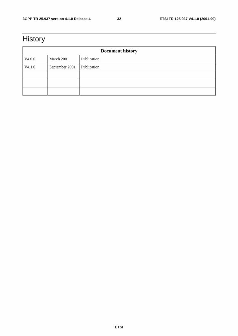
History
Document history
V4.0.0 March 2001 Publication
V4.1.0 September 2001 Publication