Toyota Truck RAV4 2WD L4-2.0L (1AZ-FE) 2002 · 2 Align the camshaft knock pin with the knock pin...
15
Timing Chain: Service and Repair Toyota Truck RAV4 2WD L4-2.0L (1AZ-FE) 2002
Transcript of Toyota Truck RAV4 2WD L4-2.0L (1AZ-FE) 2002 · 2 Align the camshaft knock pin with the knock pin...
Timing Chain: Service and Repair
Toyota Truck RAV4 2WD L4-2.0L (1AZ-FE) 2002
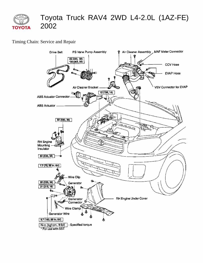
REMOVAL
NOTICE:
Under the
condition with
the timing
chain cover
removed, in
case of rotating
the camshafts,
make the
position of the
crankshaft
rotated
clockwise by
about 45° from
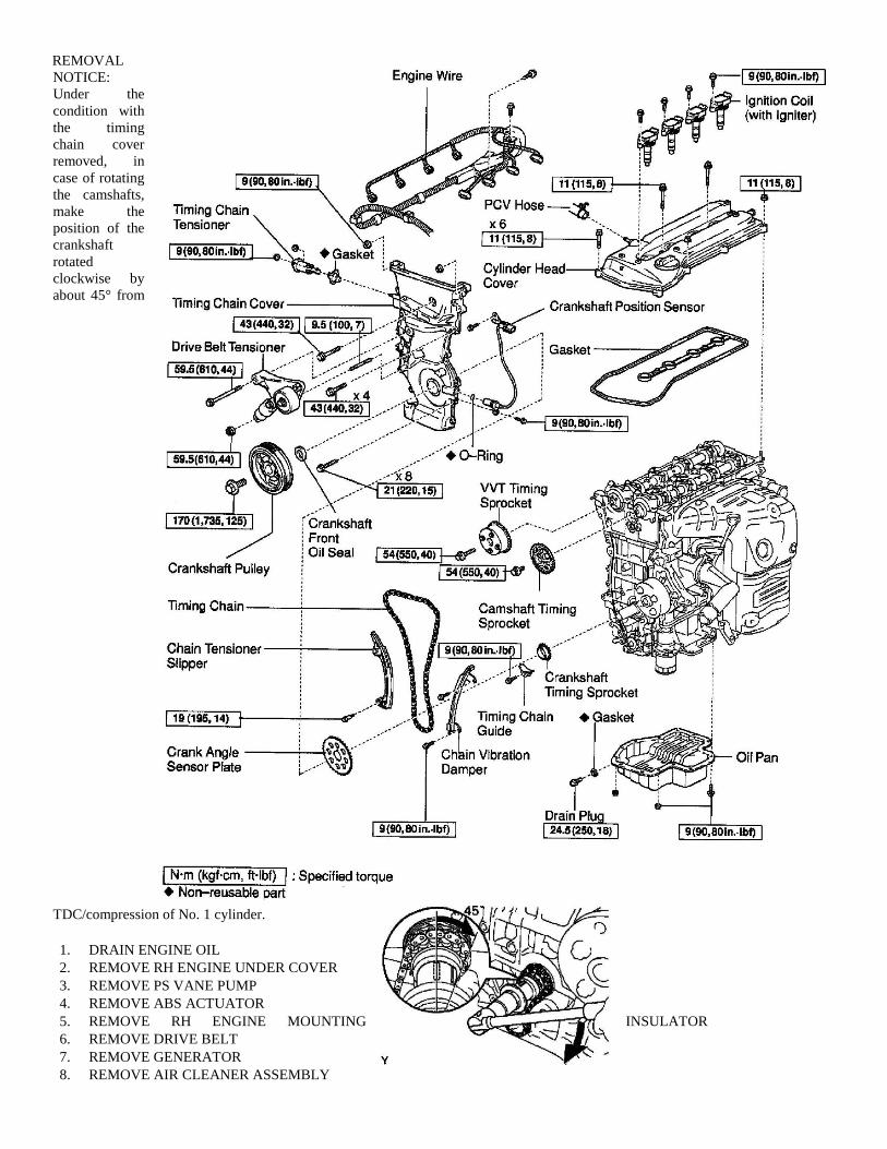
TDC/compression of No. 1 cylinder.
1. DRAIN ENGINE OIL
2. REMOVE RH ENGINE UNDER COVER
3. REMOVE PS VANE PUMP
4. REMOVE ABS ACTUATOR
5. REMOVE RH ENGINE MOUNTING INSULATOR
6. REMOVE DRIVE BELT
7. REMOVE GENERATOR
8. REMOVE AIR CLEANER ASSEMBLY
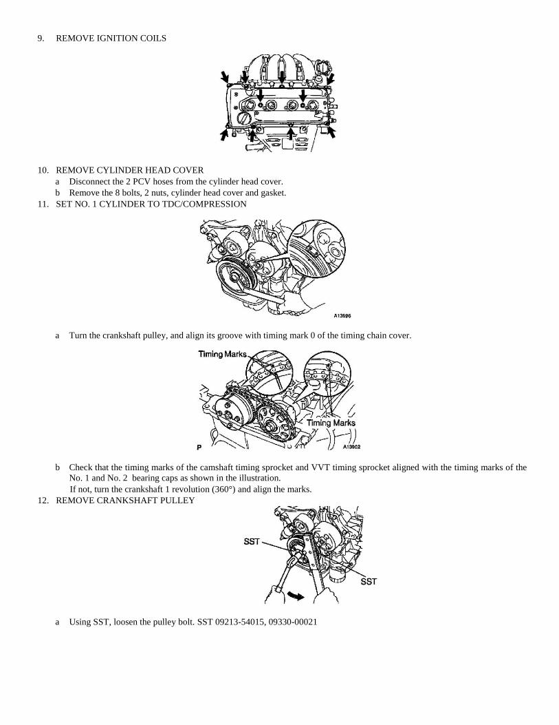
9. REMOVE IGNITION COILS
10. REMOVE CYLINDER HEAD COVER
a Disconnect the 2 PCV hoses from the cylinder head cover.
b Remove the 8 bolts, 2 nuts, cylinder head cover and gasket.
11. SET NO. 1 CYLINDER TO TDC/COMPRESSION
a Turn the crankshaft pulley, and align its groove with timing mark 0 of the timing chain cover.
b Check that the timing marks of the camshaft timing sprocket and VVT timing sprocket aligned with the timing marks of the
No. 1 and No. 2 bearing caps as shown in the illustration.
If not, turn the crankshaft 1 revolution (360°) and align the marks.
12. REMOVE CRANKSHAFT PULLEY
a Using SST, loosen the pulley bolt. SST 09213-54015, 09330-00021
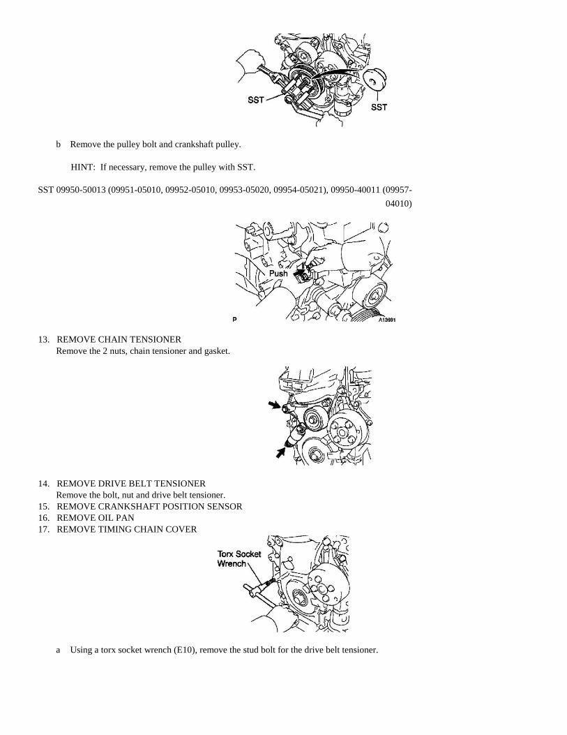
b Remove the pulley bolt and crankshaft pulley.
HINT: If necessary, remove the pulley with SST.
SST 09950-50013 (09951-05010, 09952-05010, 09953-05020, 09954-05021), 09950-40011 (09957-
04010)
13. REMOVE CHAIN TENSIONER
Remove the 2 nuts, chain tensioner and gasket.
14. REMOVE DRIVE BELT TENSIONER
Remove the bolt, nut and drive belt tensioner.
15. REMOVE CRANKSHAFT POSITION SENSOR
16. REMOVE OIL PAN
17. REMOVE TIMING CHAIN COVER
a Using a torx socket wrench (E10), remove the stud bolt for the drive belt tensioner.
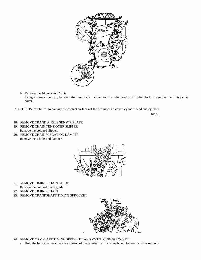
b Remove the 14 bolts and 2 nuts.
c Using a screwdriver, pry between the timing chain cover and cylinder head or cylinder block. d Remove the timing chain
cover.
NOTICE: Be careful not to damage the contact surfaces of the timing chain cover, cylinder head and cylinder
block.
18. REMOVE CRANK ANGLE SENSOR PLATE
19. REMOVE CHAIN TENSIONER SLIPPER
Remove the bolt and slipper.
20. REMOVE CHAIN VIBRATION DAMPER
Remove the 2 bolts and damper.
21. REMOVE TIMING CHAIN GUIDE
Remove the bolt and chain guide.
22. REMOVE TIMING CHAIN
23. REMOVE CRANKSHAFT TIMING SPROCKET
24. REMOVE CAMSHAFT TIMING SPROCKET AND VVT TIMING SPROCKET
a Hold the hexagonal head wrench portion of the camshaft with a wrench, and loosen the sprocket bolts.
NOTICE: Be careful not to damage the cylinder head and valve lifter by a wrench.
b Remove the bolt and exhaust camshaft timing sprocket.
c Remove the bolt and VVT timing sprocket.
NOTICE: Do not disassemble the VVT timing sprocket.
INSPECTION
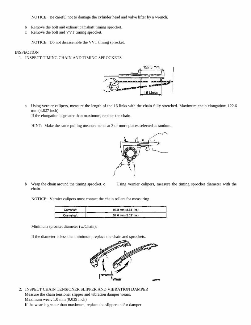
1. INSPECT TIMING CHAIN AND TIMING SPROCKETS
a Using vernier calipers, measure the length of the 16 links with the chain fully stretched. Maximum chain elongation: 122.6
mm (4.827 inch)
If the elongation is greater than maximum, replace the chain.
HINT: Make the same pulling measurements at 3 or more places selected at random.
b Wrap the chain around the timing sprocket. c Using vernier calipers, measure the timing sprocket diameter with the
chain.
NOTICE: Vernier calipers must contact the chain rollers for measuring.
Minimum sprocket diameter (w/Chain):
If the diameter is less than minimum, replace the chain and sprockets.
2. INSPECT CHAIN TENSIONER SLIPPER AND VIBRATION DAMPER
Measure the chain tensioner slipper and vibration damper wears.
Maximum wear: 1.0 mm (0.039 inch)
If the wear is greater than maximum, replace the slipper and/or damper.
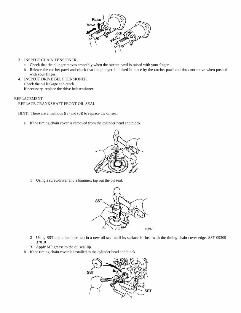
3. INSPECT CHAIN TENSIONER
a Check that the plunger moves smoothly when the ratchet pawl is raised with your finger.
b Release the ratchet pawl and check that the plunger is locked in place by the ratchet pawl and does not move when pushed
with your finger.
4. INSPECT DRIVE BELT TENSIONER
Check the oil leakage and crack.
If necessary, replace the drive belt tensioner.
REPLACEMENT
REPLACE CRANKSHAFT FRONT OIL SEAL
HINT: There are 2 methods ((a) and (b)) to replace the oil seal.
a If the timing chain cover is removed from the cylinder head and block.
1 Using a screwdriver and a hammer, tap out the oil seal.
2 Using SST and a hammer, tap in a new oil seal until its surface is flush with the timing chain cover edge. SST 09309-
37010
3 Apply MP grease to the oil seal lip.
b If the timing chain cover is installed to the cylinder head and block.
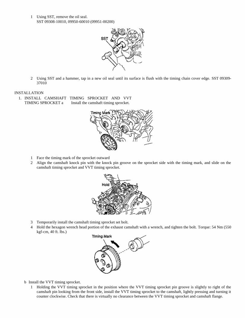
1 Using SST, remove the oil seal.
SST 09308-10010, 09950-60010 (09951-00200)
2 Using SST and a hammer, tap in a new oil seal until its surface is flush with the timing chain cover edge. SST 09309-
37010
INSTALLATION
1. INSTALL CAMSHAFT TIMING SPROCKET AND VVT
TIMING SPROCKET a Install the camshaft timing sprocket.
1 Face the timing mark of the sprocket outward
2 Align the camshaft knock pin with the knock pin groove on the sprocket side with the timing mark, and slide on the
camshaft timing sprocket and VVT timing sprocket.
3 Temporarily install the camshaft timing sprocket set bolt.
4 Hold the hexagon wrench head portion of the exhaust camshaft with a wrench, and tighten the bolt. Torque: 54 Nm (550
kgf-cm, 40 ft. lbs.)
b Install the VVT timing sprocket.
1 Holding the VVT timing sprocket in the position where the VVT timing sprocket pin groove is slightly to right of the
camshaft pin looking from the front side, install the VVT timing sprocket to the camshaft, lightly pressing and turning it
counter clockwise. Check that there is virtually no clearance between the VVT timing sprocket and camshaft flange.
NOTICE: Be careful not to turn the VVT timing sprocket clockwise when installing it.
2 Temporarily install the VVT timing sprocket bolt.
3 Hold the hexagon wrench head portion of the intake camshaft with a wrench.
4 Take care to install the VVT timing sprocket with the bolt Torque: 54 Nm (550 kgf-cm, 40 ft. lbs.)
5 Check that the valve timing controller turns clockwise and that it is locked securely when the lock pin in hole is at the
locking point.
2. SET NO. 1 CYLINDER TO TDC/COMPRESSION
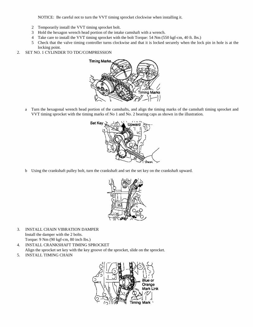
a Turn the hexagonal wrench head portion of the camshafts, and align the timing marks of the camshaft timing sprocket and
VVT timing sprocket with the timing marks of No 1 and No. 2 bearing caps as shown in the illustration.
b Using the crankshaft pulley bolt, turn the crankshaft and set the set key on the crankshaft upward.
3. INSTALL CHAIN VIBRATION DAMPER
Install the damper with the 2 bolts.
Torque: 9 Nm (90 kgf-cm, 80 inch lbs.)
4. INSTALL CRANKSHAFT TIMING SPROCKET
Align the sprocket set key with the key groove of the sprocket, slide on the sprocket.
5. INSTALL TIMING CHAIN
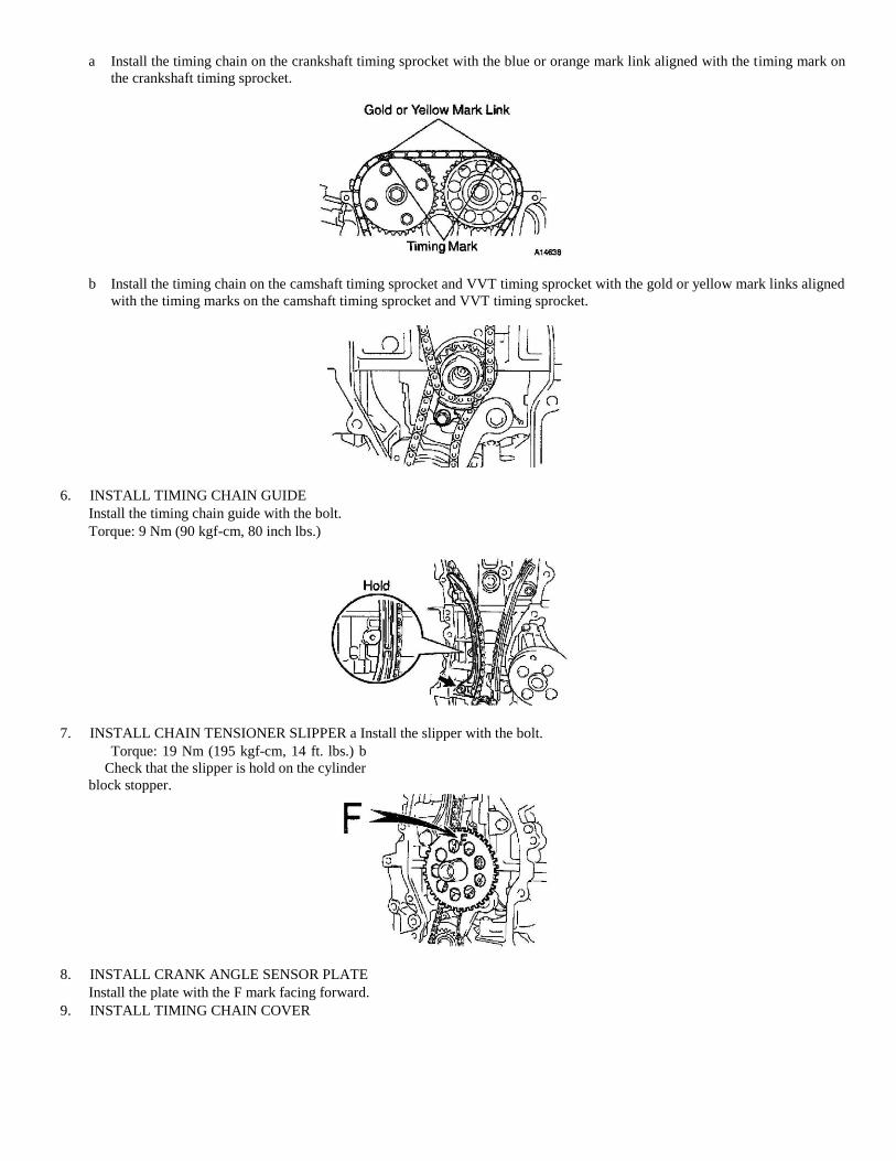
a Install the timing chain on the crankshaft timing sprocket with the blue or orange mark link aligned with the timing mark on
the crankshaft timing sprocket.
b Install the timing chain on the camshaft timing sprocket and VVT timing sprocket with the gold or yellow mark links aligned
with the timing marks on the camshaft timing sprocket and VVT timing sprocket.
6. INSTALL TIMING CHAIN GUIDE
Install the timing chain guide with the bolt.
Torque: 9 Nm (90 kgf-cm, 80 inch lbs.)
7. INSTALL CHAIN TENSIONER SLIPPER a Install the slipper with the bolt.
Torque: 19 Nm (195 kgf-cm, 14 ft. lbs.) b
Check that the slipper is hold on the cylinder
block stopper.
8. INSTALL CRANK ANGLE SENSOR PLATE
Install the plate with the F mark facing forward.
9. INSTALL TIMING CHAIN COVER
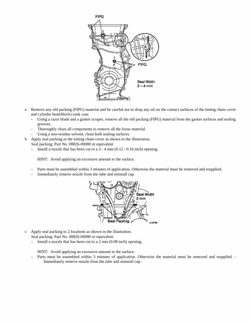
a Remove any old packing (FIPG) material and be careful not to drop any oil on the contact surfaces of the timing chain cover
and cylinder head/block/crank case.
- Using a razor blade and a gasket scraper, remove all the old packing (FIPG) material from the gasket surfaces and sealing
grooves.
- Thoroughly clean all components to remove all the loose material.
- Using a non-residue solvent, clean both sealing surfaces.
b Apply seal packing to the timing chain cover as shown in the illustration.
Seal packing: Part No. 08826-00080 or equivalent
- Install a nozzle that has been cut to a 3 - 4 mm (0.12 - 0.16 inch) opening.
HINT: Avoid applying an excessive amount to the surface.
- Parts must be assembled within 3 minutes of application. Otherwise the material must be removed and reapplied.
- Immediately remove nozzle from the tube and reinstall cap.
c Apply seal packing to 2 locations as shown in the illustration.
Seal packing: Part No. 08826-00080 or equivalent
- Install a nozzle that has been cut to a 2 mm (0.08 inch) opening.
HINT: Avoid applying an excessive amount to the surface.
- Parts must be assembled within 3 minutes of application. Otherwise the material must be removed and reapplied. -
Immediately remove nozzle from the tube and reinstall cap.
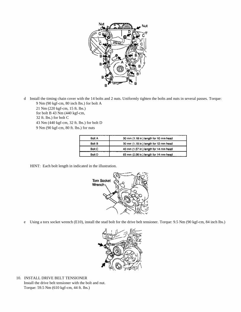
d Install the timing chain cover with the 14 bolts and 2 nuts. Uniformly tighten the bolts and nuts in several passes. Torque:
9 Nm (90 kgf-cm, 80 inch lbs.) for bolt A
21 Nm (220 kgf-cm, 15 ft. lbs.)
for bolt B 43 Nm (440 kgf-cm,
32 ft. lbs.) for bolt C
43 Nm (440 kgf-cm, 32 ft. lbs.) for bolt D
9 Nm (90 kgf-cm, 80 ft. lbs.) for nuts
HINT: Each bolt length in indicated in the illustration.
e Using a torx socket wrench (E10), install the stud bolt for the drive belt tensioner. Torque: 9.5 Nm (90 kgf-cm, 84 inch lbs.)
10. INSTALL DRIVE BELT TENSIONER
Install the drive belt tensioner with the bolt and nut.
Torque: 59.5 Nm (610 kgf-cm, 44 ft. lbs.)
NOTICE: As the drive belt tensioner should be torqued together with the timing chain cover, so be sure install it with in 15
minutes after the timing chain cover is installed.
11. INSTALL CRANKSHAFT POSITION SENSOR
12. INSTALL OIL PAN
13. INSTALL CRANKSHAFT PULLEY
a Align the pulley set key with the key groove of the pulley, and slide on the pulley.
b Using SST, install the pulley bolt.
SST 09213-54015, 09330-00021
Torque: 170 Nm (1,735 kgf-cm, 125 ft. lbs.)
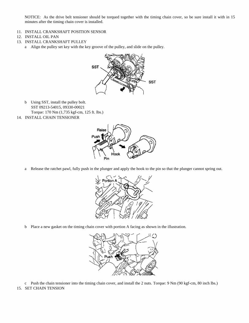
14. INSTALL CHAIN TENSIONER
a Release the ratchet pawl, fully push in the plunger and apply the hook to the pin so that the plunger cannot spring out.
b Place a new gasket on the timing chain cover with portion A facing as shown in the illustration.
c Push the chain tensioner into the timing chain cover, and install the 2 nuts. Torque: 9 Nm (90 kgf-cm, 80 inch lbs.)
15. SET CHAIN TENSION
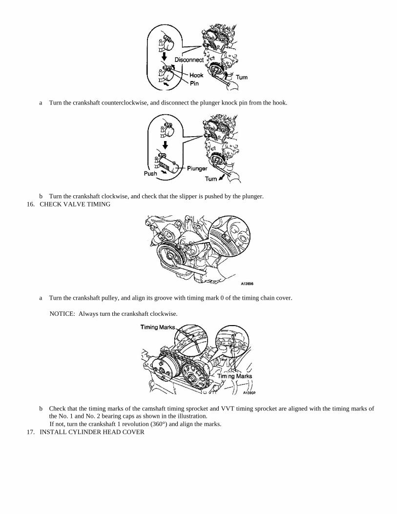
a Turn the crankshaft counterclockwise, and disconnect the plunger knock pin from the hook.
b Turn the crankshaft clockwise, and check that the slipper is pushed by the plunger.
16. CHECK VALVE TIMING
a Turn the crankshaft pulley, and align its groove with timing mark 0 of the timing chain cover.
NOTICE: Always turn the crankshaft clockwise.
b Check that the timing marks of the camshaft timing sprocket and VVT timing sprocket are aligned with the timing marks of
the No. 1 and No. 2 bearing caps as shown in the illustration.
If not, turn the crankshaft 1 revolution (360°) and align the marks.
17. INSTALL CYLINDER HEAD COVER
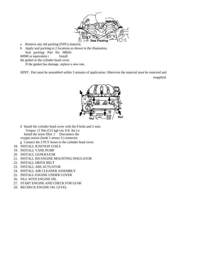
a Remove any old packing (FIPG) material.
b Apply seal packing to 2 locations as shown in the illustration.
Seal packing: Part No. 08826-
00080 or equivalent c Install
the gasket to the cylinder head cover.
If the gasket has damage, replace a new one.
HINT: Part must be assembled within 3 minutes of application. Otherwise the material must be removed and
reapplied.
d Install the cylinder head cover with the 8 bolts and 2 nuts.
Torque: 11 Nm (115 kgf-cm, 8 ft. lbs.) e Install the noise filter. f Disconnect the oxygen sensor (bank 1 sensor 1) connector.
g Connect the 2 PCV hoses to the cylinder head cover.
18. INSTALL IGNITION COILS
19. INSTALL VANE PUMP
20. INSTALL GENERATOR
21. INSTALL RH ENGINE MOUNTING INSULATOR
22. INSTALL DRIVE BELT
23. INSTALL ABS ACTUATOR
24. INSTALL AIR CLEANER ASSEMBLY
25. INSTALL ENGINE UNDER COVER
26. FILL WITH ENGINE OIL
27. START ENGINE AND CHECK FOR LEAK
28. RECHECK ENGINE OIL LEVEL