FUEL PUMP CAMSHAFT TIMING CHECK - f01.justanswer.com · 26-02-2018 · If the crankshaft timing...
45
PUBLISHED: 26-FEB-2018 2010.0 RANGE ROVER SPORT (LS), 303-01 ENGINE - V8 S/C 5.0L PETROL FUEL PUMP CAMSHAFT TIMING CHECK (G1473740) GENERAL PROCEDURES 19.90.16 HIGH PRESSURE FUEL TIMING CHECK 5000 CC, AJ V8 0.90 USED WITHINS SPECIAL TOOL(S) 303-1447 Timing Tool
Transcript of FUEL PUMP CAMSHAFT TIMING CHECK - f01.justanswer.com · 26-02-2018 · If the crankshaft timing...
PUBLISHED: 26-FEB-20182010.0 RANGE ROVER SPORT (LS), 303-01
ENGINE - V8 S/C 5.0L PETROL
FUEL PUMP CAMSHAFT TIMING CHECK (G1473740)
GENERAL PROCEDURES
19.90.16
HIGH PRESSURE
FUEL TIMING CHECK
5000 CC, AJ V8
0.90USED
WITHINS
SPECIAL TOOL(S)
303-1447Timing Tool
PART(S)
STEP PART NAME QUANTITY
Check Step 14 Brake vacuum pump seal 1
Check Step 17 Oil pan drain plug 1
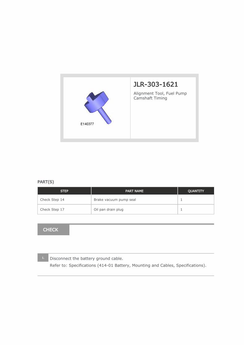
JLR-303-1621Alignment Tool, Fuel Pump Camshaft Timing
CHECK
Disconnect the battery ground cable.
Refer to: Specifications (414-01 Battery, Mounting and Cables, Specifications).
1.
WARNING:
Do not work on or under a vehicle supported only by a jack. Always
support the vehicle on safety stands.
Raise and support the vehicle.
2.
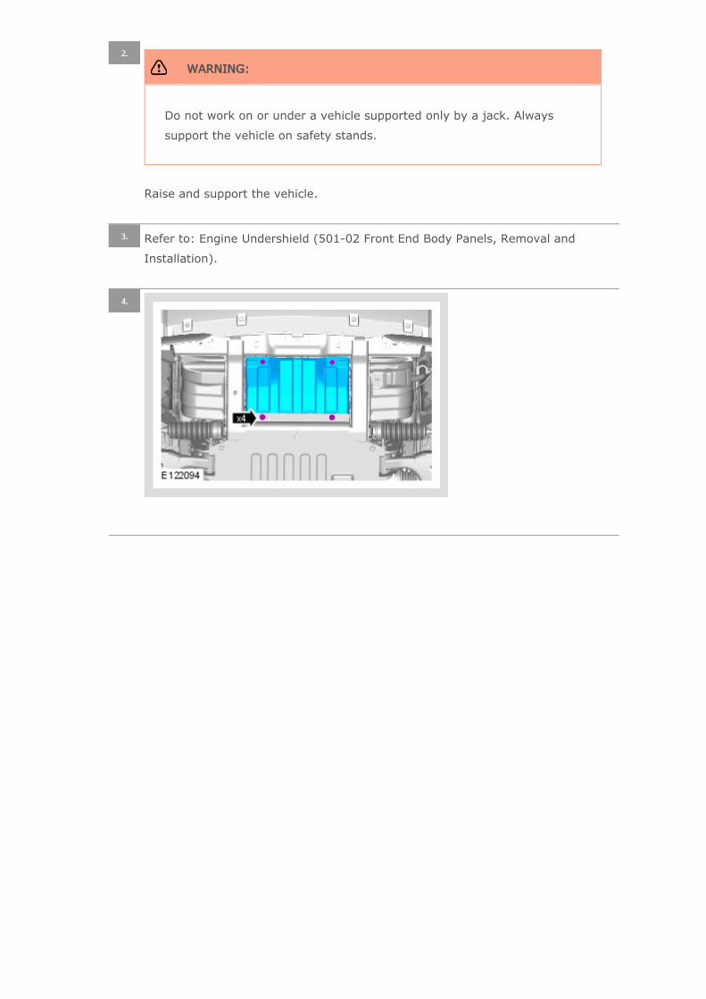
Refer to: Engine Undershield (501-02 Front End Body Panels, Removal and
Installation).
3.
4.
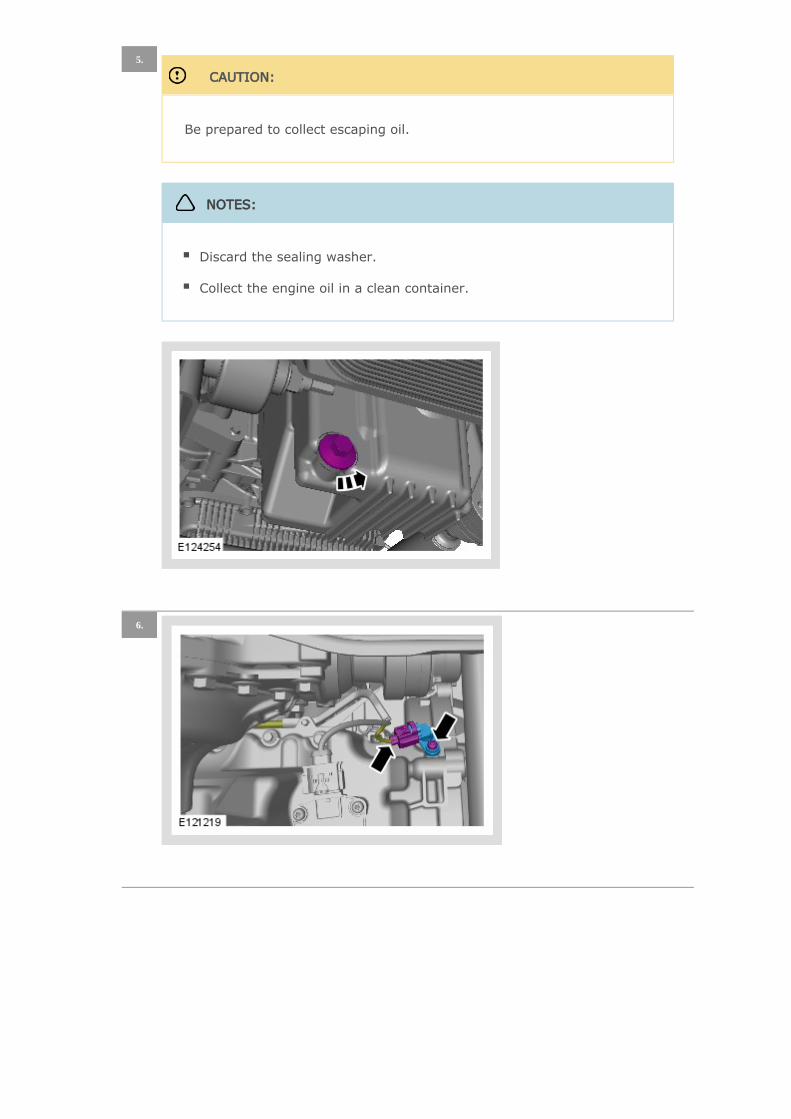
CAUTION:
Be prepared to collect escaping oil.
5.
NOTES:
Discard the sealing washer.
Collect the engine oil in a clean container.
6.
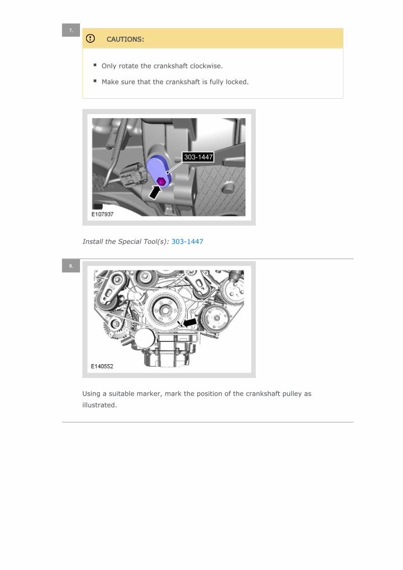
CAUTIONS:
Only rotate the crankshaft clockwise.
Make sure that the crankshaft is fully locked.
Install the Special Tool(s): 303-1447
7.
Using a suitable marker, mark the position of the crankshaft pulley as
illustrated.
8.
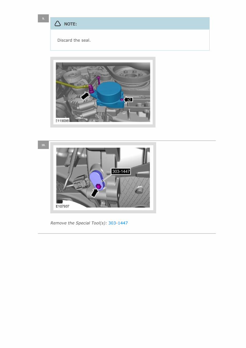
9.
NOTE:
Discard the seal.
Remove the Special Tool(s): 303-1447
10.
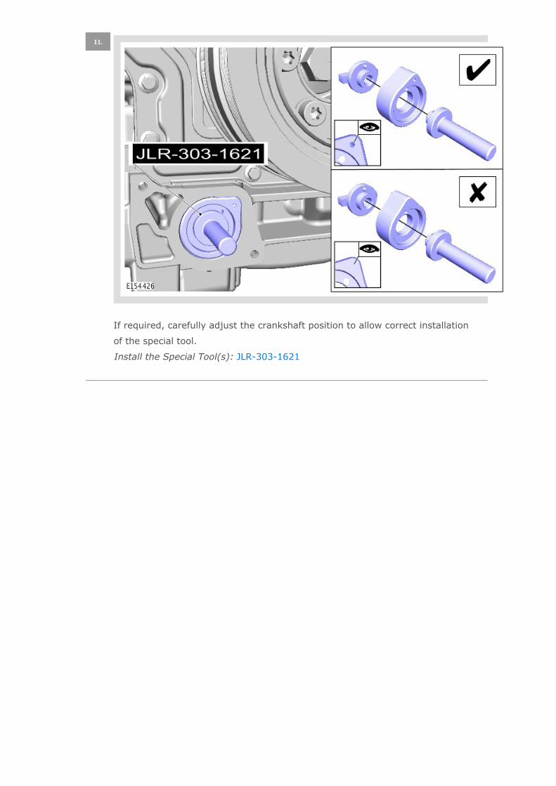
If required, carefully adjust the crankshaft position to allow correct installation
of the special tool.
Install the Special Tool(s): JLR-303-1621
11.
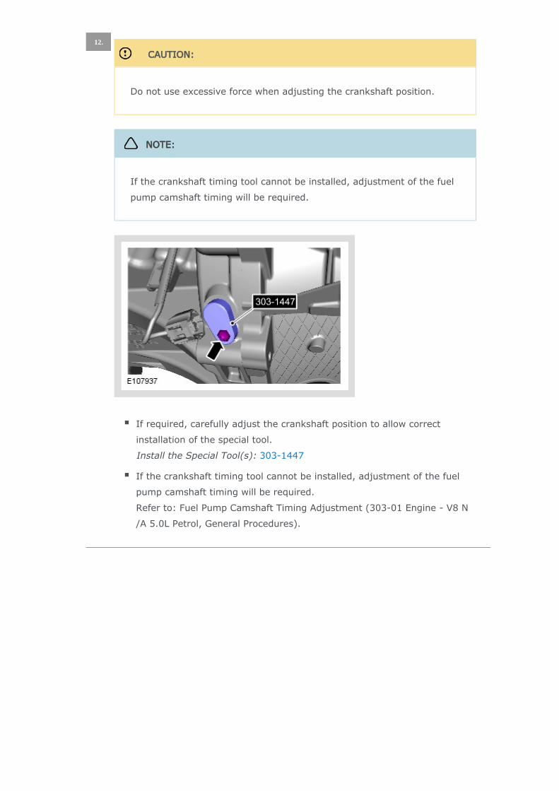
CAUTION:
Do not use excessive force when adjusting the crankshaft position.
If required, carefully adjust the crankshaft position to allow correct
installation of the special tool.
Install the Special Tool(s): 303-1447
If the crankshaft timing tool cannot be installed, adjustment of the fuel
pump camshaft timing will be required.
Refer to: Fuel Pump Camshaft Timing Adjustment (303-01 Engine - V8 N
/A 5.0L Petrol, General Procedures).
12.
NOTE:
If the crankshaft timing tool cannot be installed, adjustment of the fuel
pump camshaft timing will be required.
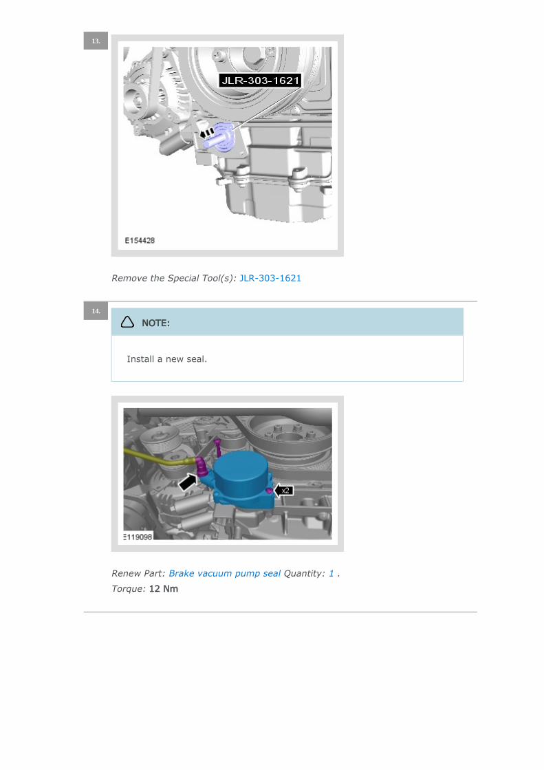
Remove the Special Tool(s): JLR-303-1621
13.
Renew Part: Quantity: .Brake vacuum pump seal 1
Torque: 12 Nm
14.
NOTE:
Install a new seal.
Remove the Special Tool(s): 303-1447
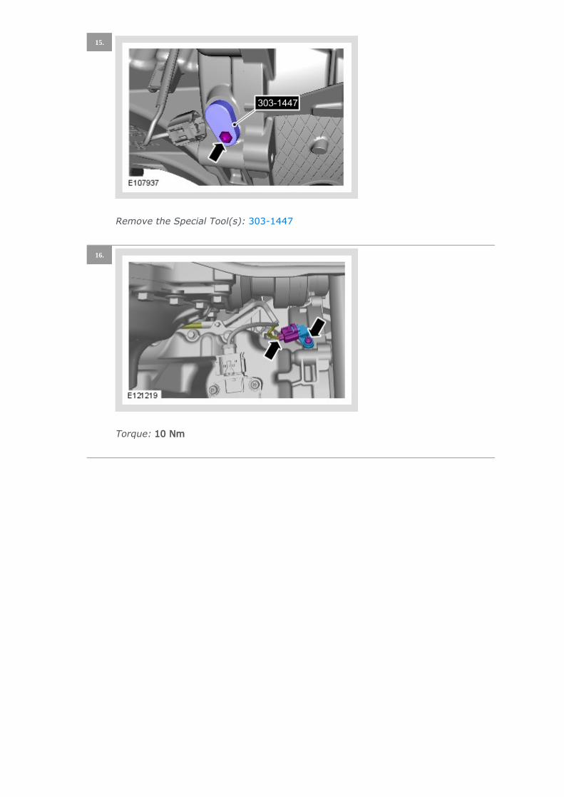
15.
Torque: 10 Nm
16.
Renew Part: Quantity: .Oil pan drain plug 1
Torque: 24 Nm
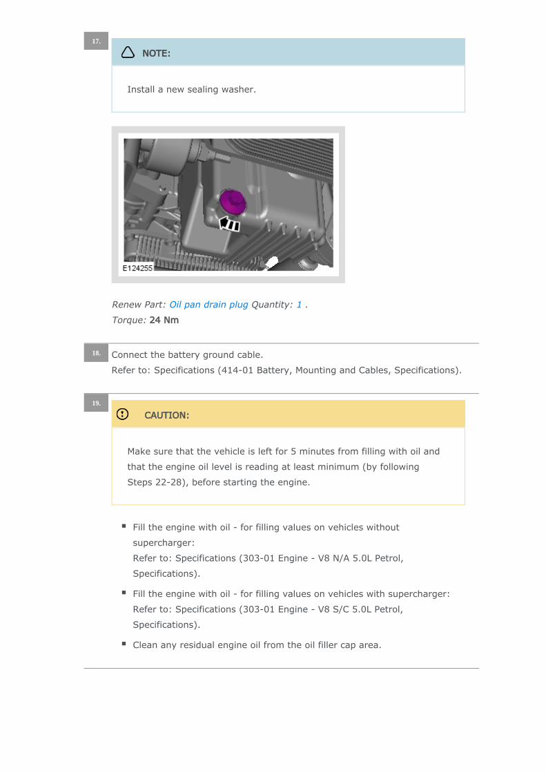
17.
NOTE:
Install a new sealing washer.
Connect the battery ground cable.
Refer to: Specifications (414-01 Battery, Mounting and Cables, Specifications).
18.
CAUTION:
Make sure that the vehicle is left for 5 minutes from filling with oil and
that the engine oil level is reading at least minimum (by following
Steps 22-28), before starting the engine.
Fill the engine with oil - for filling values on vehicles without
supercharger:
Refer to: Specifications (303-01 Engine - V8 N/A 5.0L Petrol,
Specifications).
Fill the engine with oil - for filling values on vehicles with supercharger:
Refer to: Specifications (303-01 Engine - V8 S/C 5.0L Petrol,
Specifications).
Clean any residual engine oil from the oil filler cap area.
19.
CAUTION:
Make sure that the vehicle has been left for 5 minutes from filling with
oil.
Follow the Steps 22-28 before starting the engine.
20.
Start the engine and allow to run for 10 minutes, stop the engine.
Check for leaks.
21.
CAUTIONS:
Make sure that the selector lever and the gearshift mechanism are in
the park (P) position.
Make sure that the hood is open.
Turn the ignition on.
22.
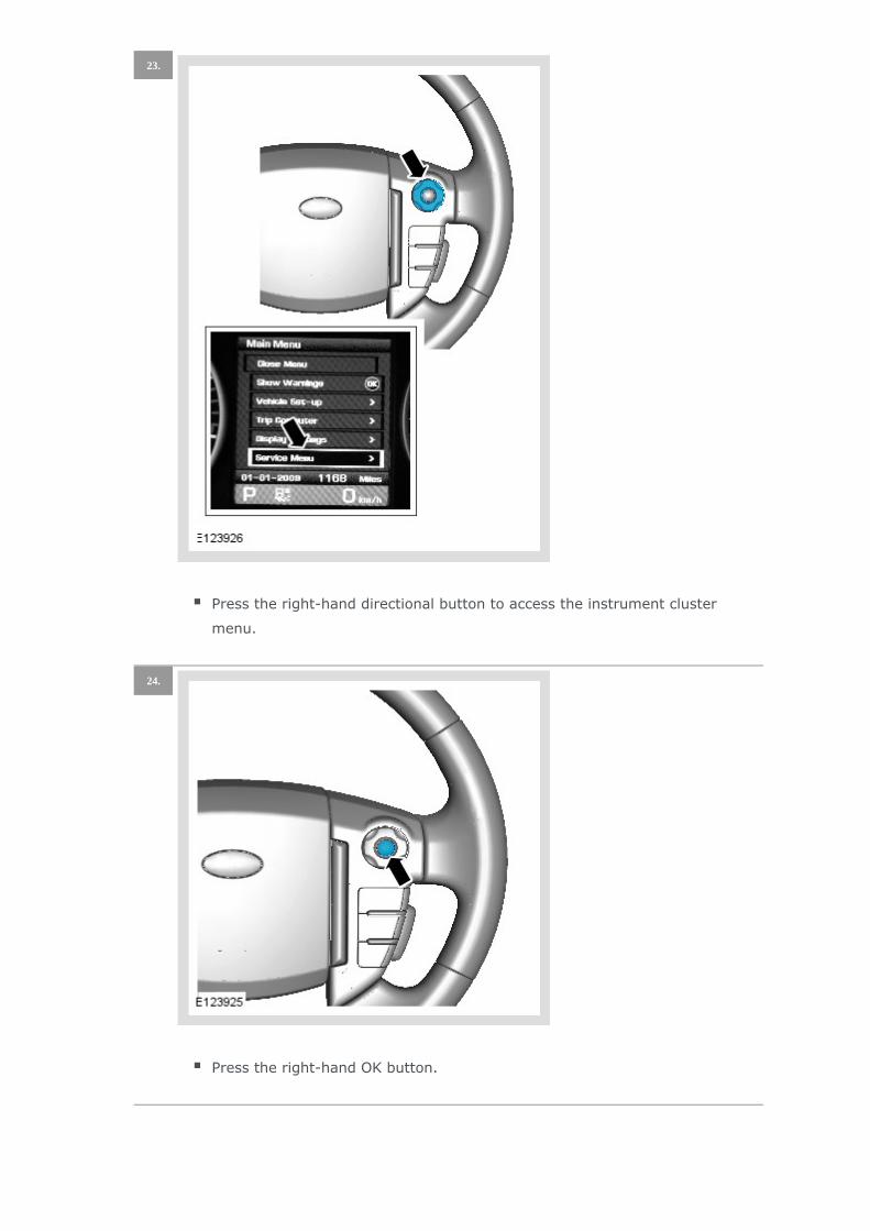
Press the right-hand directional button to access the instrument cluster
menu.
23.
Press the right-hand OK button.
24.

Press the right-hand directional button to access the Oil Level Display.
25.

Press the right-hand OK button and follow the instructions.
26.
Press the cruise control cancel button twice within 2 seconds.
27.

The message center display will revert to the normal display in the trip
computer.
Press the right-hand OK button and follow the instructions.
Check that the oil level display shows an oil level reading.
Only after having started and run the engine for 10 minutes (as indicated
in Step 21), switch off the engine, then stabilizing for 10 minutes, take a
reading from the oil level display and, if necessary top up with engine oil.
28.
Turn the ignition off.
29.
NOTE:
If instructed to follow Steps 22-28 in a previous step, return to Step 21
and continue the procedure.
Allow 10 minutes for the engine oil level to stabilize if there has been
additional oil top up.
30.
Turn the ignition on.
Press and hold the cruise control cancel button for more than 2 seconds.
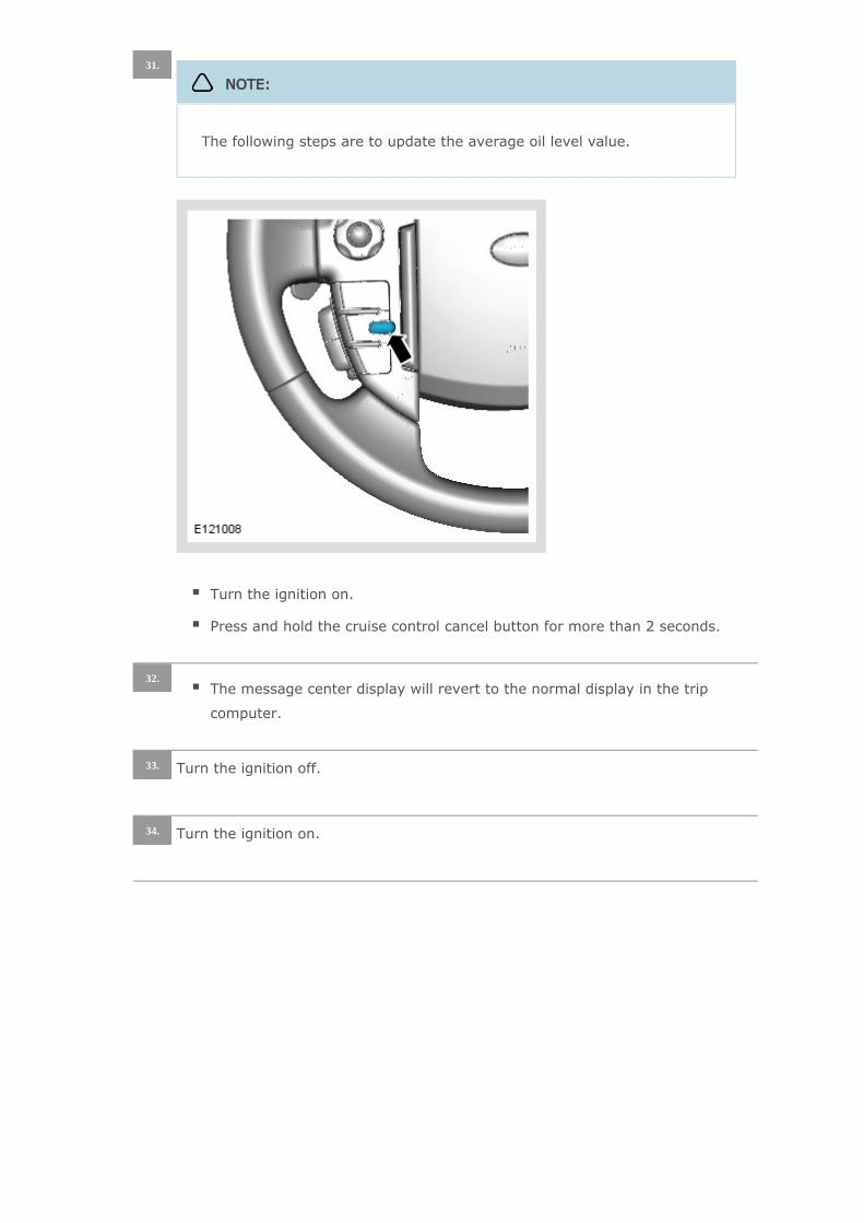
31.
NOTE:
The following steps are to update the average oil level value.
The message center display will revert to the normal display in the trip
computer.
32.
Turn the ignition off.33.
Turn the ignition on.34.

Press the right-hand directional button to access the instrument cluster
menu.
35.
Press the right-hand OK button.
36.

Press the right-hand directional button to access the Oil Level Display.
37.
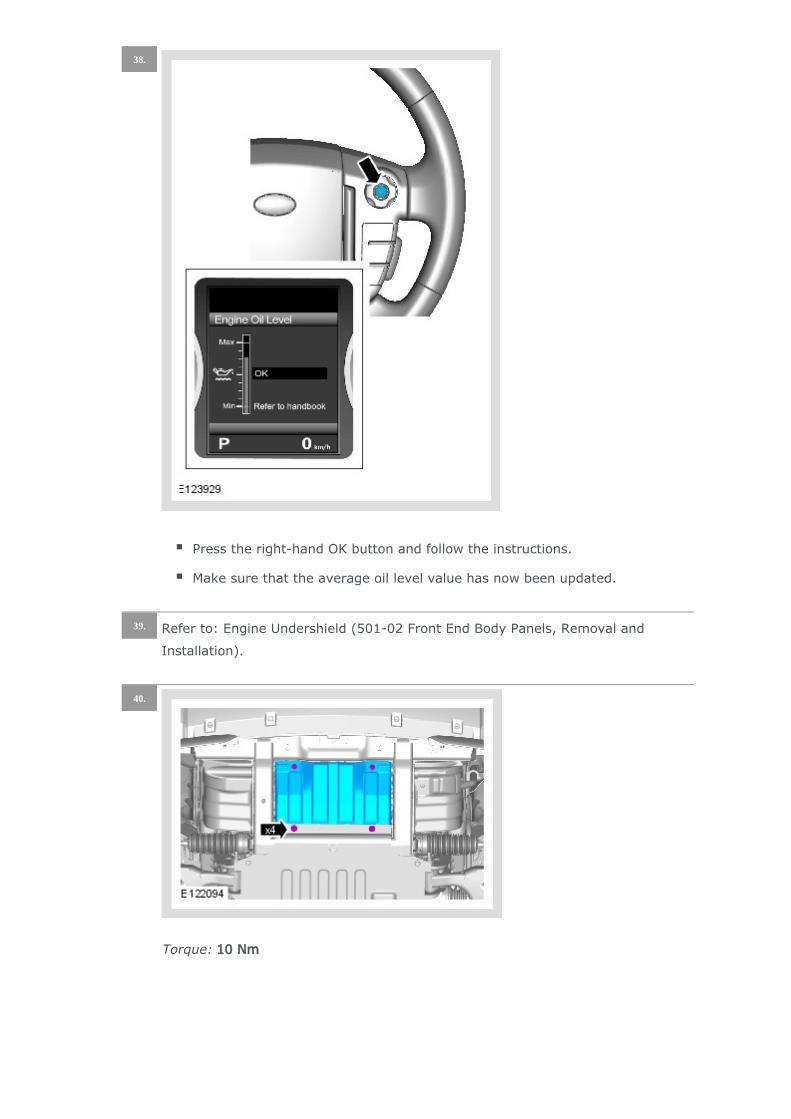
Press the right-hand OK button and follow the instructions.
Make sure that the average oil level value has now been updated.
38.
Refer to: Engine Undershield (501-02 Front End Body Panels, Removal and
Installation).
39.
Torque: 10 Nm
40.
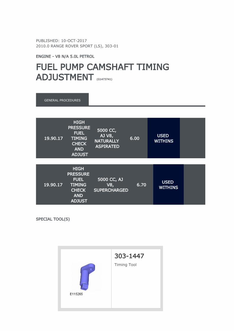
PUBLISHED: 10-OCT-20172010.0 RANGE ROVER SPORT (LS), 303-01
ENGINE - V8 N/A 5.0L PETROL
FUEL PUMP CAMSHAFT TIMING ADJUSTMENT (G1473741)
GENERAL PROCEDURES
19.90.17
HIGH PRESSURE
FUEL TIMING CHECK AND
ADJUST
5000 CC, AJ V8,
NATURALLY ASPIRATED
6.00USED
WITHINS
19.90.17
HIGH PRESSURE
FUEL TIMING CHECK AND
ADJUST
5000 CC, AJ V8,
SUPERCHARGED6.70
USED WITHINS
SPECIAL TOOL(S)
303-1447Timing Tool
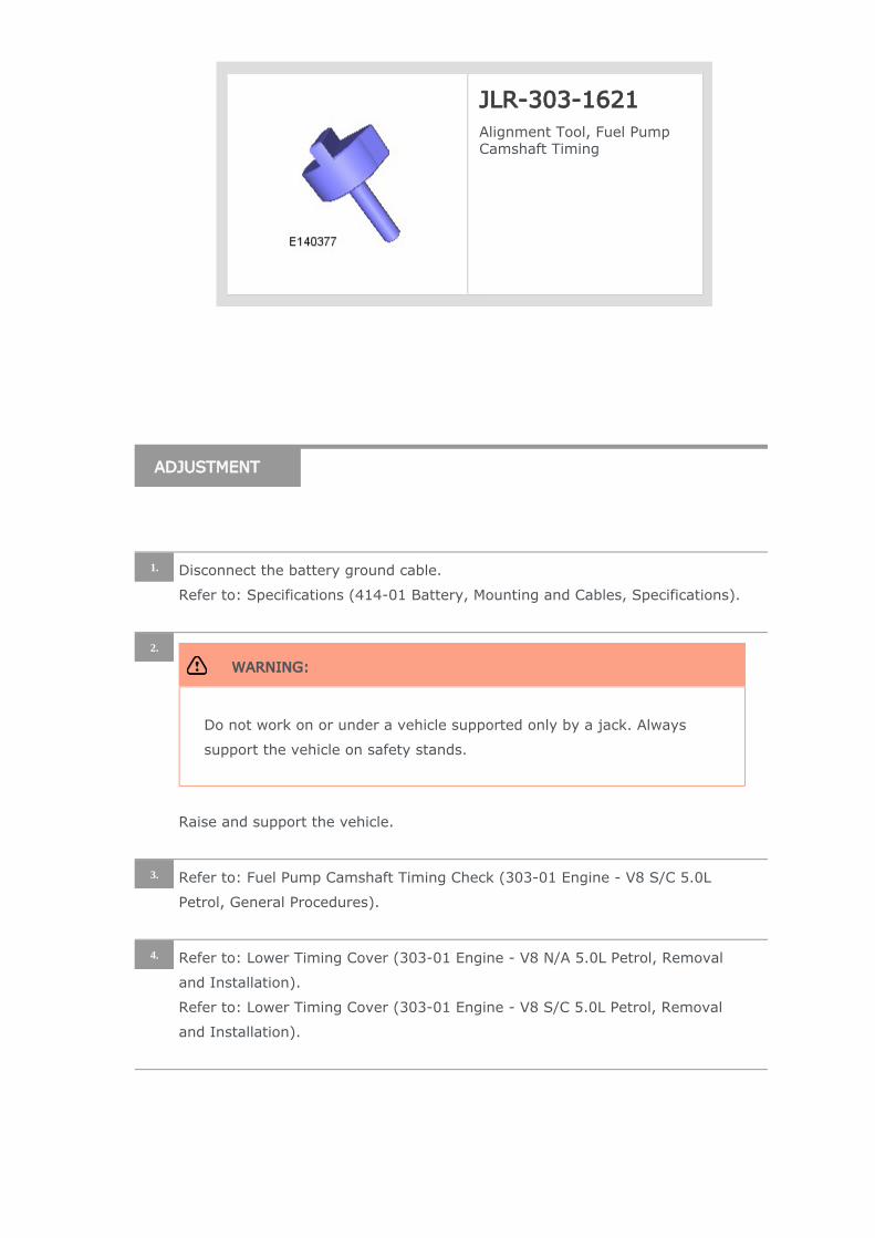
JLR-303-1621Alignment Tool, Fuel Pump Camshaft Timing
ADJUSTMENT
Disconnect the battery ground cable.
Refer to: Specifications (414-01 Battery, Mounting and Cables, Specifications).
1.
WARNING:
Do not work on or under a vehicle supported only by a jack. Always
support the vehicle on safety stands.
Raise and support the vehicle.
2.
Refer to: Fuel Pump Camshaft Timing Check (303-01 Engine - V8 S/C 5.0L
Petrol, General Procedures).
3.
Refer to: Lower Timing Cover (303-01 Engine - V8 N/A 5.0L Petrol, Removal
and Installation).
Refer to: Lower Timing Cover (303-01 Engine - V8 S/C 5.0L Petrol, Removal
and Installation).
4.
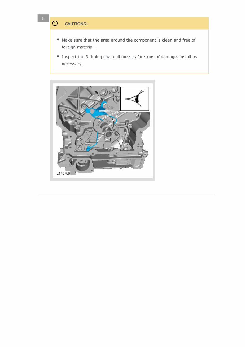
CAUTIONS:
Make sure that the area around the component is clean and free of
foreign material.
Inspect the 3 timing chain oil nozzles for signs of damage, install as
necessary.
5.
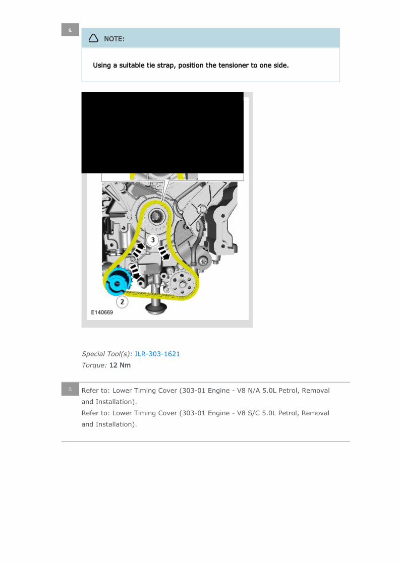
Special Tool(s): JLR-303-1621
Torque: 12 Nm
6.
NOTE:
Using a suitable tie strap, position the tensioner to one side.
Refer to: Lower Timing Cover (303-01 Engine - V8 N/A 5.0L Petrol, Removal
and Installation).
Refer to: Lower Timing Cover (303-01 Engine - V8 S/C 5.0L Petrol, Removal
and Installation).
7.
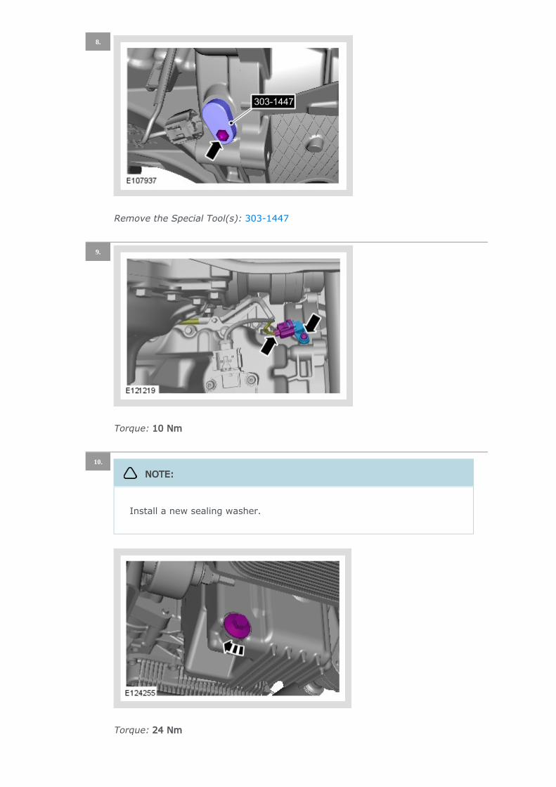
Remove the Special Tool(s): 303-1447
8.
Torque: 10 Nm
9.
Torque: 24 Nm
10.
NOTE:
Install a new sealing washer.
Connect the battery ground cable.
Refer to: Specifications (414-01 Battery, Mounting and Cables, Specifications).
11.
CAUTION:
Make sure that the vehicle is left for 5 minutes from filling with oil and
that the engine oil level is reading at least minimum (by following
Steps 15-21), before starting the engine.
Fill the engine with oil - for filling values on vehicles without
supercharger:
Refer to: Specifications (303-01 Engine - V8 N/A 5.0L Petrol,
Specifications).
Fill the engine with oil - for filling values on vehicles with supercharger:
Refer to: Specifications (303-01 Engine - V8 S/C 5.0L Petrol,
Specifications).
Clean any residual engine oil from the oil filler cap area.
12.
CAUTION:
Make sure that the vehicle has been left for 5 minutes from filling with
oil.
Follow the Steps 15-21 before starting the engine.
13.
Start the engine and allow to run for 10 minutes, stop the engine.
Check for leaks.
14.
CAUTIONS:
Make sure that the selector lever and the gearshift mechanism are in
the park (P) position.
Make sure that the hood is open.
Turn the ignition on.
15.

Press the right-hand directional button to access the instrument cluster
menu.
16.
Press the right-hand OK button.
17.
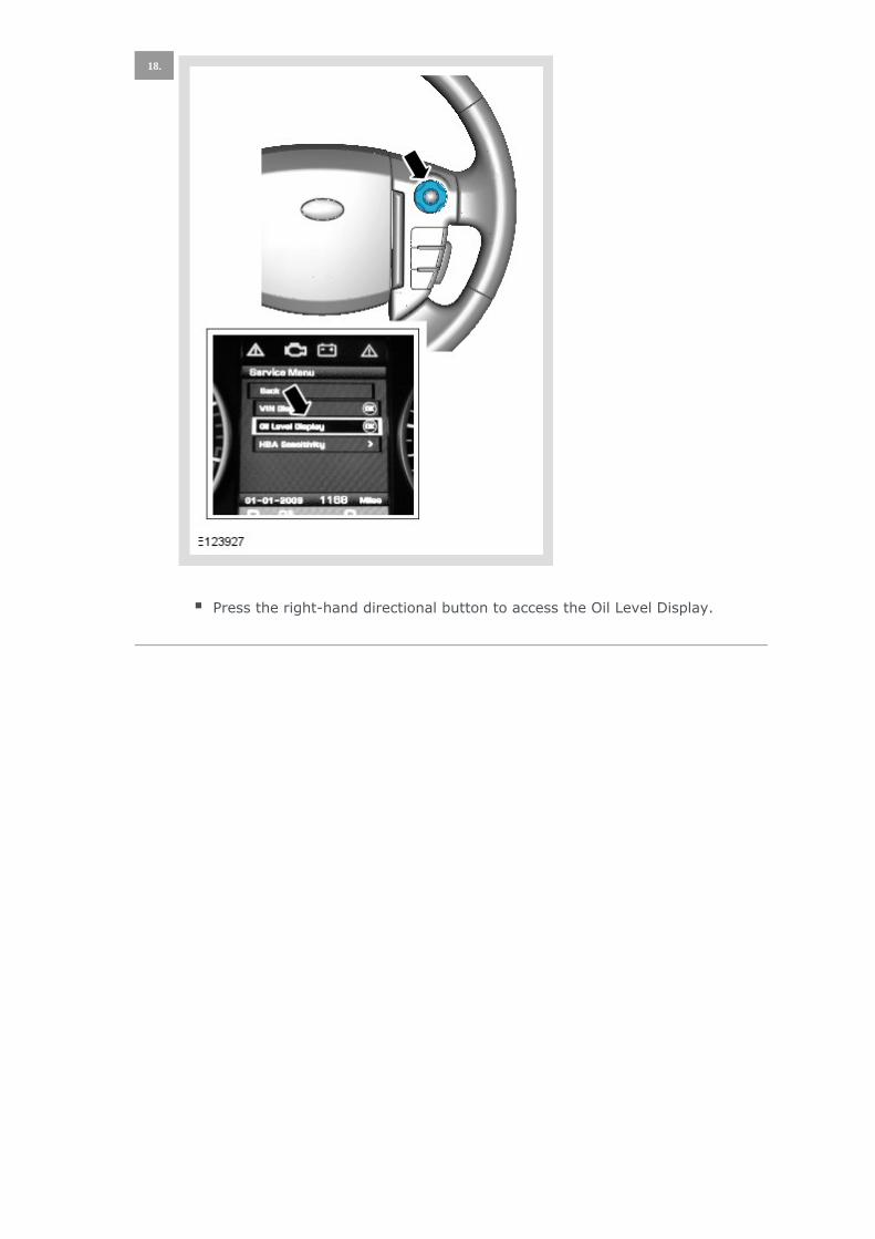
Press the right-hand directional button to access the Oil Level Display.
18.
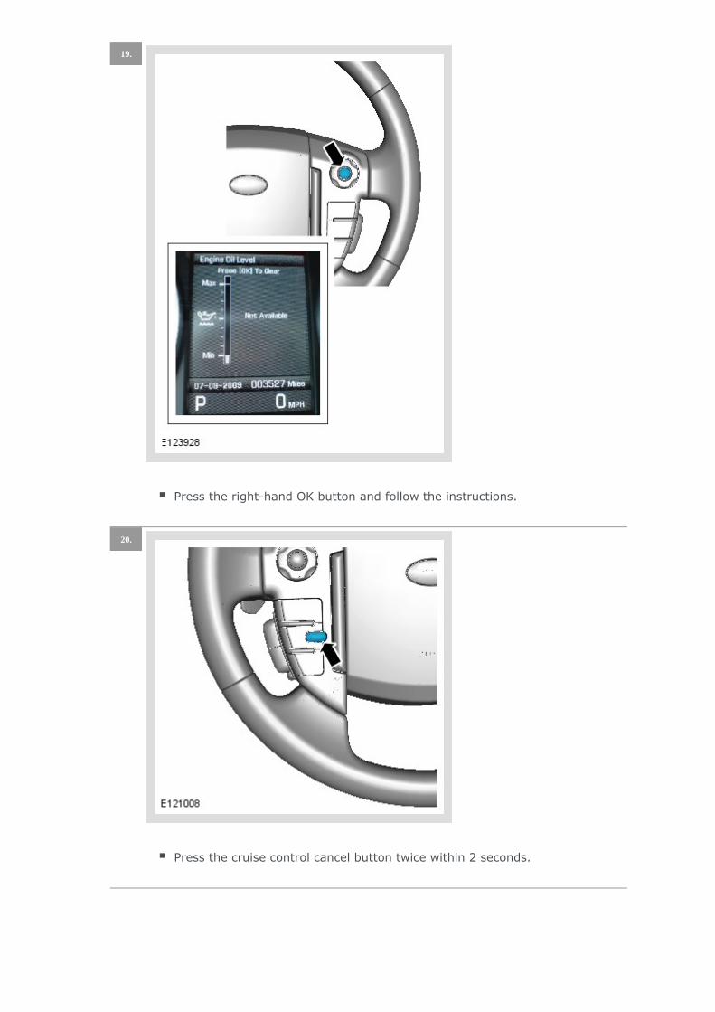
Press the right-hand OK button and follow the instructions.
19.
Press the cruise control cancel button twice within 2 seconds.
20.
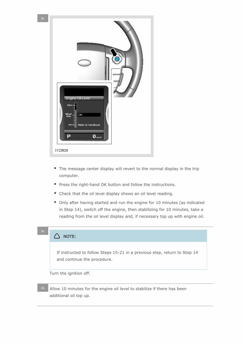
The message center display will revert to the normal display in the trip
computer.
Press the right-hand OK button and follow the instructions.
Check that the oil level display shows an oil level reading.
Only after having started and run the engine for 10 minutes (as indicated
in Step 14), switch off the engine, then stabilizing for 10 minutes, take a
reading from the oil level display and, if necessary top up with engine oil.
21.
Turn the ignition off.
22.
NOTE:
If instructed to follow Steps 15-21 in a previous step, return to Step 14
and continue the procedure.
Allow 10 minutes for the engine oil level to stabilize if there has been
additional oil top up.
23.

Turn the ignition on.
Press and hold the cruise control cancel button for more than 2 seconds.
24.
NOTE:
The following steps are to update the average oil level value.
The message center display will revert to the normal display in the trip
computer.
25.
Turn the ignition off.26.
Turn the ignition on.27.

Press the right-hand directional button to access the instrument cluster
menu.
28.
Press the right-hand OK button.
29.

Press the right-hand directional button to access the Oil Level Display.
30.

Press the right-hand OK button and follow the instructions.
Make sure that the average oil level value has now been updated.
31.
Refer to: Engine Undershield (501-02 Front End Body Panels, Removal and
Installation).
32.
Torque: 10 Nm
33.
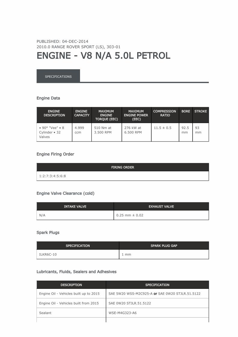
PUBLISHED: 04-DEC-20142010.0 RANGE ROVER SPORT (LS), 303-01
ENGINE - V8 N/A 5.0L PETROL
SPECIFICATIONS
Engine Data
ENGINE DESCRIPTION
ENGINE CAPACITY
MAXIMUM ENGINE
TORQUE (EEC)
MAXIMUM ENGINE POWER
(EEC)
COMPRESSION RATIO
BORE STROKE
• 90° "Vee" • 8 Cylinder • 32 Valves
4.999 ccm
510 Nm at 3.500 RPM
276 kW at 6.500 RPM
11.5 ± 0.5 92.5 mm
93 mm
Engine Firing Order
FIRING ORDER
1:2:7:3:4:5:6:8
Engine Valve Clearance (cold)
INTAKE VALVE EXHAUST VALVE
N/A 0.25 mm ± 0.02
Spark Plugs
SPECIFICATION SPARK PLUG GAP
ILKR6C-10 1 mm
Lubricants, Fluids, Sealers and Adhesives
DESCRIPTION SPECIFICATION
Engine Oil - Vehicles built up to 2015 SAE 5W20 WSS-M2C925-A SAE 0W20 STJLR.51.5122or
Engine Oil - Vehicles built from 2015 SAE 0W20 STJLR.51.5122
Sealant WSE-M4G323-A6
Core plug and stub pipe retainer WSK-M2G349-A7
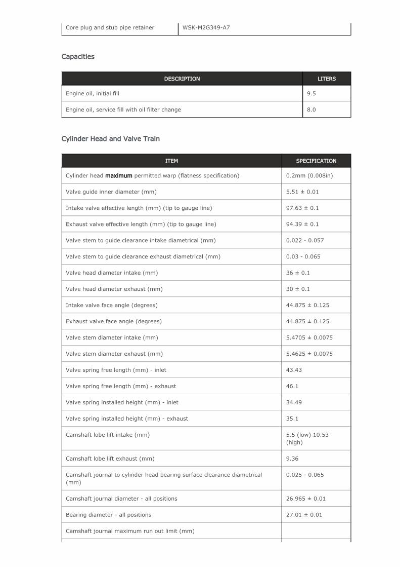
Capacities
DESCRIPTION LITERS
Engine oil, initial fill 9.5
Engine oil, service fill with oil filter change 8.0
Cylinder Head and Valve Train
ITEM SPECIFICATION
Cylinder head permitted warp (flatness specification)maximum 0.2mm (0.008in)
Valve guide inner diameter (mm) 5.51 ± 0.01
Intake valve effective length (mm) (tip to gauge line) 97.63 ± 0.1
Exhaust valve effective length (mm) (tip to gauge line) 94.39 ± 0.1
Valve stem to guide clearance intake diametrical (mm) 0.022 - 0.057
Valve stem to guide clearance exhaust diametrical (mm) 0.03 - 0.065
Valve head diameter intake (mm) 36 ± 0.1
Valve head diameter exhaust (mm) 30 ± 0.1
Intake valve face angle (degrees) 44.875 ± 0.125
Exhaust valve face angle (degrees) 44.875 ± 0.125
Valve stem diameter intake (mm) 5.4705 ± 0.0075
Valve stem diameter exhaust (mm) 5.4625 ± 0.0075
Valve spring free length (mm) - inlet 43.43
Valve spring free length (mm) - exhaust 46.1
Valve spring installed height (mm) - inlet 34.49
Valve spring installed height (mm) - exhaust 35.1
Camshaft lobe lift intake (mm) 5.5 (low) 10.53 (high)
Camshaft lobe lift exhaust (mm) 9.36
Camshaft journal to cylinder head bearing surface clearance diametrical (mm)
0.025 - 0.065
Camshaft journal diameter - all positions 26.965 ± 0.01
Bearing diameter - all positions 27.01 ± 0.01
Camshaft journal maximum run out limit (mm)
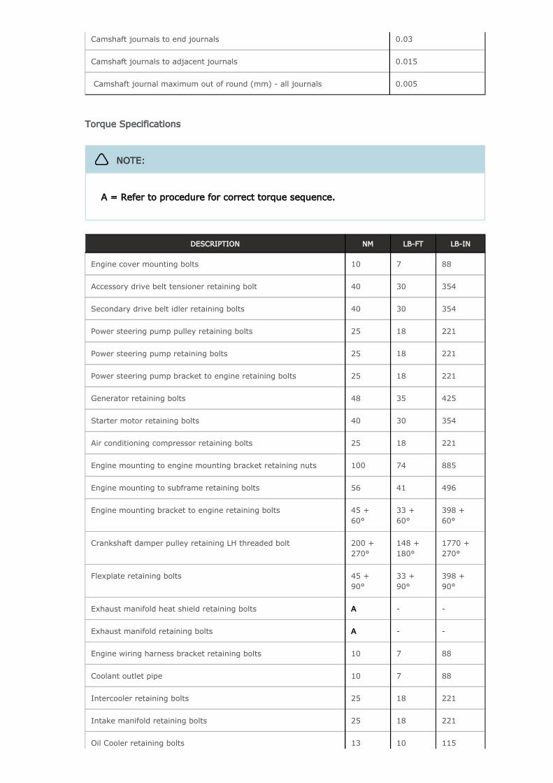
Camshaft journals to end journals 0.03
Camshaft journals to adjacent journals 0.015
Camshaft journal maximum out of round (mm) - all journals 0.005
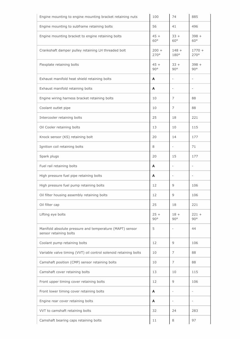
Torque Specifications
DESCRIPTION NM LB-FT LB-IN
Engine cover mounting bolts 10 7 88
Accessory drive belt tensioner retaining bolt 40 30 354
Secondary drive belt idler retaining bolts 40 30 354
Power steering pump pulley retaining bolts 25 18 221
Power steering pump retaining bolts 25 18 221
Power steering pump bracket to engine retaining bolts 25 18 221
Generator retaining bolts 48 35 425
Starter motor retaining bolts 40 30 354
Air conditioning compressor retaining bolts 25 18 221
Engine mounting to engine mounting bracket retaining nuts 100 74 885
Engine mounting to subframe retaining bolts 56 41 496
Engine mounting bracket to engine retaining bolts 45 + 60°
33 + 60°
398 + 60°
Crankshaft damper pulley retaining LH threaded bolt 200 + 270°
148 + 180°
1770 + 270°
Flexplate retaining bolts 45 + 90°
33 + 90°
398 + 90°
Exhaust manifold heat shield retaining bolts A - -
Exhaust manifold retaining bolts A - -
Engine wiring harness bracket retaining bolts 10 7 88
Coolant outlet pipe 10 7 88
Intercooler retaining bolts 25 18 221
Intake manifold retaining bolts 25 18 221
Oil Cooler retaining bolts 13 10 115
NOTE:
A = Refer to procedure for correct torque sequence.
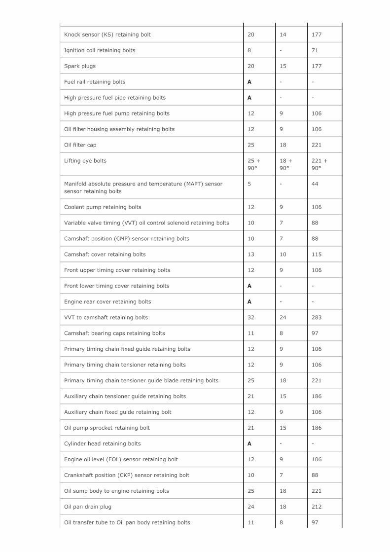
Knock sensor (KS) retaining bolt 20 14 177
Ignition coil retaining bolts 8 - 71
Spark plugs 20 15 177
Fuel rail retaining bolts A - -
High pressure fuel pipe retaining bolts A - -
High pressure fuel pump retaining bolts 12 9 106
Oil filter housing assembly retaining bolts 12 9 106
Oil filter cap 25 18 221
Lifting eye bolts 25 + 90°
18 + 90°
221 + 90°
Manifold absolute pressure and temperature (MAPT) sensor sensor retaining bolts
5 - 44
Coolant pump retaining bolts 12 9 106
Variable valve timing (VVT) oil control solenoid retaining bolts 10 7 88
Camshaft position (CMP) sensor retaining bolts 10 7 88
Camshaft cover retaining bolts 13 10 115
Front upper timing cover retaining bolts 12 9 106
Front lower timing cover retaining bolts A - -
Engine rear cover retaining bolts A - -
VVT to camshaft retaining bolts 32 24 283
Camshaft bearing caps retaining bolts 11 8 97
Primary timing chain fixed guide retaining bolts 12 9 106
Primary timing chain tensioner retaining bolts 12 9 106
Primary timing chain tensioner guide blade retaining bolts 25 18 221
Auxiliary chain tensioner guide retaining bolts 21 15 186
Auxiliary chain fixed guide retaining bolt 12 9 106
Oil pump sprocket retaining bolt 21 15 186
Cylinder head retaining bolts A - -
Engine oil level (EOL) sensor retaining bolt 12 9 106
Crankshaft position (CKP) sensor retaining bolt 10 7 88
Oil sump body to engine retaining bolts 25 18 221
Oil pan drain plug 24 18 212
Oil transfer tube to Oil pan body retaining bolts 11 8 97
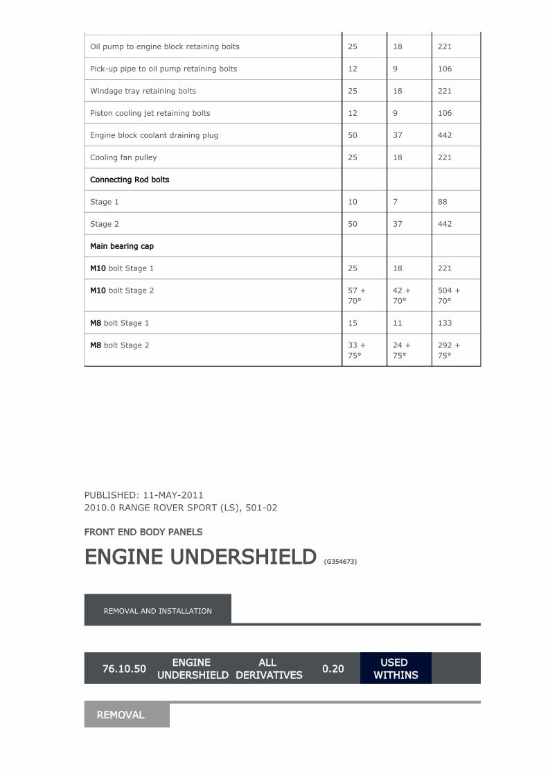
PUBLISHED: 11-MAY-20112010.0 RANGE ROVER SPORT (LS), 501-02
FRONT END BODY PANELS
ENGINE UNDERSHIELD (G354673)
Oil pump to engine block retaining bolts 25 18 221
Pick-up pipe to oil pump retaining bolts 12 9 106
Windage tray retaining bolts 25 18 221
Piston cooling jet retaining bolts 12 9 106
Engine block coolant draining plug 50 37 442
Cooling fan pulley 25 18 221
Connecting Rod bolts
Stage 1 10 7 88
Stage 2 50 37 442
Main bearing cap
bolt Stage 1M10 25 18 221
bolt Stage 2M10 57 + 70°
42 + 70°
504 + 70°
bolt Stage 1M8 15 11 133
bolt Stage 2M8 33 + 75°
24 + 75°
292 + 75°
REMOVAL AND INSTALLATION
76.10.50ENGINE
UNDERSHIELDALL
DERIVATIVES0.20
USED WITHINS
REMOVAL
PUBLISHED: 13-JUL-20112010.0 RANGE ROVER SPORT (LS), 414-01
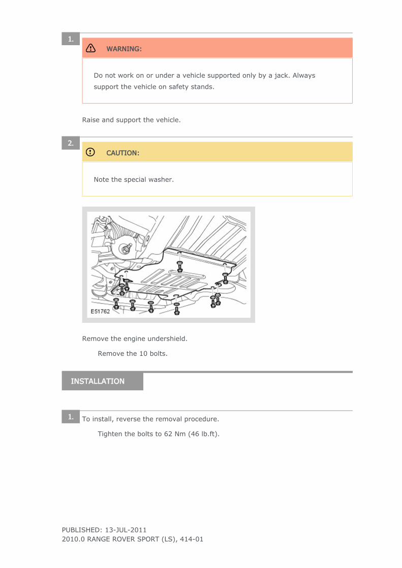
WARNING:
Do not work on or under a vehicle supported only by a jack. Always
support the vehicle on safety stands.
Raise and support the vehicle.
1.
CAUTION:
Note the special washer.
Remove the engine undershield.
2.
Remove the 10 bolts.
INSTALLATION
To install, reverse the removal procedure.1.
Tighten the bolts to 62 Nm (46 lb.ft).
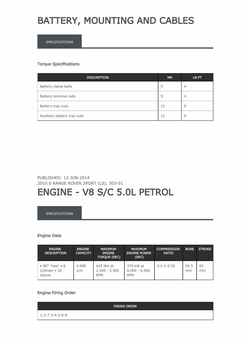
BATTERY, MOUNTING AND CABLES
PUBLISHED: 12-JUN-20142010.0 RANGE ROVER SPORT (LS), 303-01
ENGINE - V8 S/C 5.0L PETROL
SPECIFICATIONS
Torque Specifications
DESCRIPTION NM LB-FT
Battery clamp bolts 5 4
Battery terminal nuts 5 4
Battery tray nuts 12 9
Auxiliary battery tray nuts 12 9
SPECIFICATIONS
Engine Data
ENGINE DESCRIPTION
ENGINE CAPACITY
MAXIMUM ENGINE
TORQUE (EEC)
MAXIMUM ENGINE POWER
(EEC)
COMPRESSION RATIO
BORE STROKE
• 90° "Vee" • 8 Cylinder • 32 Valves
4.999 ccm
625 Nm at 2.500 - 5.500 RPM
375 kW at 6.000 - 6.500 RPM
9.5 ± 0.50 92.5 mm
93 mm
Engine Firing Order
FIRING ORDER
1:2:7:3:4:5:6:8
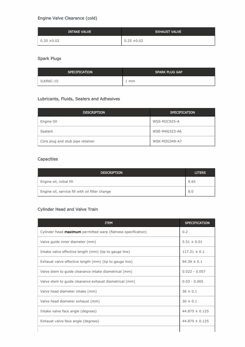
Engine Valve Clearance (cold)
INTAKE VALVE EXHAUST VALVE
0.20 ±0.02 0.25 ±0.02
Spark Plugs
SPECIFICATION SPARK PLUG GAP
ILKR6C-10 1 mm
Lubricants, Fluids, Sealers and Adhesives
DESCRIPTION SPECIFICATION
Engine Oil WSS-M2C925-A
Sealant WSE-M4G323-A6
Core plug and stub pipe retainer WSK-M2G349-A7
Capacities
DESCRIPTION LITERS
Engine oil, initial fill 9.65
Engine oil, service fill with oil filter change 8.0
Cylinder Head and Valve Train
ITEM SPECIFICATION
Cylinder head permitted warp (flatness specification)maximum 0.2
Valve guide inner diameter (mm) 5.51 ± 0.01
Intake valve effective length (mm) (tip to gauge line) 117.21 ± 0.1
Exhaust valve effective length (mm) (tip to gauge line) 94.39 ± 0.1
Valve stem to guide clearance intake diametrical (mm) 0.022 - 0.057
Valve stem to guide clearance exhaust diametrical (mm) 0.03 - 0.065
Valve head diameter intake (mm) 36 ± 0.1
Valve head diameter exhaust (mm) 30 ± 0.1
Intake valve face angle (degrees) 44.875 ± 0.125
Exhaust valve face angle (degrees) 44.875 ± 0.125
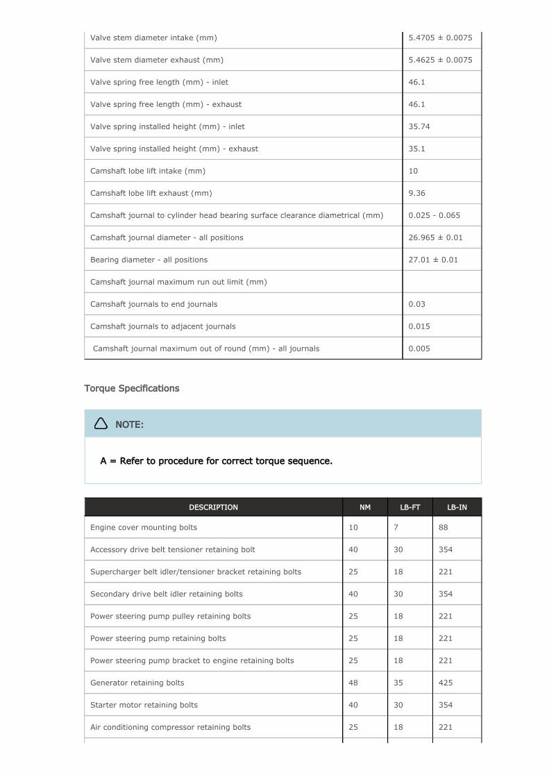
Valve stem diameter intake (mm) 5.4705 ± 0.0075
Valve stem diameter exhaust (mm) 5.4625 ± 0.0075
Valve spring free length (mm) - inlet 46.1
Valve spring free length (mm) - exhaust 46.1
Valve spring installed height (mm) - inlet 35.74
Valve spring installed height (mm) - exhaust 35.1
Camshaft lobe lift intake (mm) 10
Camshaft lobe lift exhaust (mm) 9.36
Camshaft journal to cylinder head bearing surface clearance diametrical (mm) 0.025 - 0.065
Camshaft journal diameter - all positions 26.965 ± 0.01
Bearing diameter - all positions 27.01 ± 0.01
Camshaft journal maximum run out limit (mm)
Camshaft journals to end journals 0.03
Camshaft journals to adjacent journals 0.015
Camshaft journal maximum out of round (mm) - all journals 0.005
Torque Specifications
DESCRIPTION NM LB-FT LB-IN
Engine cover mounting bolts 10 7 88
Accessory drive belt tensioner retaining bolt 40 30 354
Supercharger belt idler/tensioner bracket retaining bolts 25 18 221
Secondary drive belt idler retaining bolts 40 30 354
Power steering pump pulley retaining bolts 25 18 221
Power steering pump retaining bolts 25 18 221
Power steering pump bracket to engine retaining bolts 25 18 221
Generator retaining bolts 48 35 425
Starter motor retaining bolts 40 30 354
Air conditioning compressor retaining bolts 25 18 221
NOTE:
A = Refer to procedure for correct torque sequence.
Engine mounting to engine mounting bracket retaining nuts 100 74 885
Engine mounting to subframe retaining bolts 56 41 496
Engine mounting bracket to engine retaining bolts 45 + 60°
33 + 60°
398 + 60°
Crankshaft damper pulley retaining LH threaded bolt 200 + 270°
148 + 180°
1770 + 270°
Flexplate retaining bolts 45 + 90°
33 + 90°
398 + 90°
Exhaust manifold heat shield retaining bolts A - -
Exhaust manifold retaining bolts A - -
Engine wiring harness bracket retaining bolts 10 7 88
Coolant outlet pipe 10 7 88
Intercooler retaining bolts 25 18 221
Oil Cooler retaining bolts 13 10 115
Knock sensor (KS) retaining bolt 20 14 177
Ignition coil retaining bolts 8 - 71
Spark plugs 20 15 177
Fuel rail retaining bolts A - -
High pressure fuel pipe retaining bolts A - -
High pressure fuel pump retaining bolts 12 9 106
Oil filter housing assembly retaining bolts 12 9 106
Oil filter cap 25 18 221
Lifting eye bolts 25 + 90°
18 + 90°
221 + 90°
Manifold absolute pressure and temperature (MAPT) sensor sensor retaining bolts
5 - 44
Coolant pump retaining bolts 12 9 106
Variable valve timing (VVT) oil control solenoid retaining bolts 10 7 88
Camshaft position (CMP) sensor retaining bolts 10 7 88
Camshaft cover retaining bolts 13 10 115
Front upper timing cover retaining bolts 12 9 106
Front lower timing cover retaining bolts A - -
Engine rear cover retaining bolts A - -
VVT to camshaft retaining bolts 32 24 283
Camshaft bearing caps retaining bolts 11 8 97
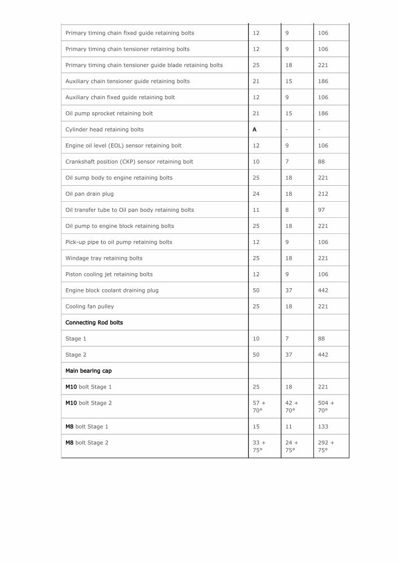
Primary timing chain fixed guide retaining bolts 12 9 106
Primary timing chain tensioner retaining bolts 12 9 106
Primary timing chain tensioner guide blade retaining bolts 25 18 221
Auxiliary chain tensioner guide retaining bolts 21 15 186
Auxiliary chain fixed guide retaining bolt 12 9 106
Oil pump sprocket retaining bolt 21 15 186
Cylinder head retaining bolts A - -
Engine oil level (EOL) sensor retaining bolt 12 9 106
Crankshaft position (CKP) sensor retaining bolt 10 7 88
Oil sump body to engine retaining bolts 25 18 221
Oil pan drain plug 24 18 212
Oil transfer tube to Oil pan body retaining bolts 11 8 97
Oil pump to engine block retaining bolts 25 18 221
Pick-up pipe to oil pump retaining bolts 12 9 106
Windage tray retaining bolts 25 18 221
Piston cooling jet retaining bolts 12 9 106
Engine block coolant draining plug 50 37 442
Cooling fan pulley 25 18 221
Connecting Rod bolts
Stage 1 10 7 88
Stage 2 50 37 442
Main bearing cap
bolt Stage 1M10 25 18 221
bolt Stage 2M10 57 + 70°
42 + 70°
504 + 70°
bolt Stage 1M8 15 11 133
bolt Stage 2M8 33 + 75°
24 + 75°
292 + 75°