Towards Scalable Network Emulation: Channel Accuracy Versus
9
Towards Scalable Network Emulation: Channel Accuracy Versus Implementation Resources Pengda Huang, Matthew Jordan Tonnemacher, Yongjiu Du, Dinesh Rajan, and Joseph Camp Electrical Engineering, Southern Methodist University {phuang, mtonnemach, ydu, rajand, camp}@smu.edu Abstract—Channel emulators are valuable tools for control- lable and repeatable wireless experimentation. Often, however, the high cost of such emulators preclude their widespread usage, especially in large-scale wireless networks. Moreover, existing channel emulators offer either very realistic channels for simplis- tic topologies or complex topologies with highly-abstracted, low- fidelity channels. To bridge the gap in offering a low-cost channel emulation solution which can scale to a large network size, in this paper, we study the tradeoff in channel emulation fidelity versus the hardware resources consumed using both analytical modeling and FPGA-based implementation. To reduce the memory foot- print of our design, we optimize our channel emulation using an iterative structure to generate the Rayleigh fading channel. In addition, the channel update rate and word length selection are also evaluated in the paper which greatly improve the efficiency of implementation. We then extend our analysis of a single channel to understand how the implementation scales for the emulation of a large-scale wireless network, showing that up to 24 vehicular channels can be emulated in real-time on a single Virtex-4 FPGA. I. I NTRODUCTION Today’s channel emulators allow extensive experimentation on complex wireless channels that can be controlled and repeated to evaluate protocols and hardware platforms directly in the same instance of an environment. Unfortunately, the emulators with the greatest channel fidelity are often limited to a single link and have a high cost [1], precluding larger-scale network emulation and widespread use by the research com- munity. Conversely, many have used software-based simulators which scale to thousands of nodes but have very basic wireless channels [2]. There have been some efforts to build emulators that scale to a network, often using FPGAs and/or DSPs (e.g., up to 15 nodes [3]). However, to enable large-scale emulation, the degree to which the channel becomes more accurate at the cost of hardware resources must be fully understood. In this paper, we study the tradeoff in channel emulation ac- curacy versus the implementation resources consumed, using both analytical modeling and FPGA-based implementation. We optimize our channel emulation using an iterative struc- ture to generate the Rayleigh fading channel with a reduced memory footprint. The channel update rate and word-length selection are also analyzed to improve implementation effi- ciency and experimentally show the efficacy of our iteration- based scheme. We then leverage the tradeoffs in emulating a single wireless path as a fundamental building block to scale to a large wireless network emulator, designing a metric for implementation complexity. This work was supported by the U.S. National Science Foundation under Grants CNS-0958436, CNS-1040429, and CNS-1150215 Fig. 1. Scalable wireless network emulation by exploiting knowledge of channel fidelity versus implementation resource costs. To envision how the emulation would scale, Fig. 1 presents a general framework for our system design. A large number of wireless transmitters and receivers (i.e., units under test) are physically connected to the bank of hardware necessary to implement the wireless network emulator, and many different connectivity matrices, topologies, and mobility patterns can be emulated. A control PC allows the design and control of the experiment. On the back end, FPGAs implement the channel emulation from the RF front end to the channel output. To enable these FPGAs to generate a large number of the necessary fading wireless channels and know the amount of hardware required, the implementation resource consumption must be understood and optimized according to the size of the network. To lay the foundation for realizing such a vision, we present the following contributions in this work: 1) A novel Autoregressive (AR) model based Rayleigh fading channel generator is proposed. Prior channel gen- eration solutions employing Sum-Of-Sinusoids (SOS) for Rayleigh fading channels demand large volumes of memory to store quantized cosine values. Since the memory resources available on FPGAs is limited, we implement our AR-based fading channel generator using a second order iterative structure which greatly reduces the amount of memory used. 2) Update rate selection and word length are jointly ana- lyzed. Word-length and channel status update rate se- lection also affect hardware resource optimization on an FPGA. A tradeoff exists between the fading channel accuracy and word length selected. A high channel status update rate will increase the computational burden on the FPGA. Therefore, we design an optimization algorithm for jointly considering word length and update rate to reduce hardware resource consumption. 3) The scalability of wireless the network emulator is
Transcript of Towards Scalable Network Emulation: Channel Accuracy Versus

Towards Scalable Network Emulation: ChannelAccuracy Versus Implementation Resources
Pengda Huang, Matthew Jordan Tonnemacher, Yongjiu Du, Dinesh Rajan, and Joseph CampElectrical Engineering, Southern Methodist University{phuang, mtonnemach, ydu, rajand, camp}@smu.edu
Abstract—Channel emulators are valuable tools for control-lable and repeatable wireless experimentation. Often, however,the high cost of such emulators preclude their widespread usage,especially in large-scale wireless networks. Moreover, existingchannel emulators offer either very realistic channels for simplis-tic topologies or complex topologies with highly-abstracted, low-fidelity channels. To bridge the gap in offering a low-cost channelemulation solution which can scale to a large network size, in thispaper, we study the tradeoff in channel emulation fidelity versusthe hardware resources consumed using both analytical modelingand FPGA-based implementation. To reduce the memory foot-print of our design, we optimize our channel emulation using aniterative structure to generate the Rayleigh fading channel. Inaddition, the channel update rate and word length selection arealso evaluated in the paper which greatly improve the efficiency ofimplementation. We then extend our analysis of a single channelto understand how the implementation scales for the emulationof a large-scale wireless network, showing that up to 24 vehicularchannels can be emulated in real-time on a single Virtex-4 FPGA.
I. INTRODUCTION
Today’s channel emulators allow extensive experimentationon complex wireless channels that can be controlled andrepeated to evaluate protocols and hardware platforms directlyin the same instance of an environment. Unfortunately, theemulators with the greatest channel fidelity are often limitedto a single link and have a high cost [1], precluding larger-scalenetwork emulation and widespread use by the research com-munity. Conversely, many have used software-based simulatorswhich scale to thousands of nodes but have very basic wirelesschannels [2]. There have been some efforts to build emulatorsthat scale to a network, often using FPGAs and/or DSPs (e.g.,up to 15 nodes [3]). However, to enable large-scale emulation,the degree to which the channel becomes more accurate at thecost of hardware resources must be fully understood.
In this paper, we study the tradeoff in channel emulation ac-curacy versus the implementation resources consumed, usingboth analytical modeling and FPGA-based implementation.We optimize our channel emulation using an iterative struc-ture to generate the Rayleigh fading channel with a reducedmemory footprint. The channel update rate and word-lengthselection are also analyzed to improve implementation effi-ciency and experimentally show the efficacy of our iteration-based scheme. We then leverage the tradeoffs in emulating asingle wireless path as a fundamental building block to scaleto a large wireless network emulator, designing a metric forimplementation complexity.
This work was supported by the U.S. National Science Foundation underGrants CNS-0958436, CNS-1040429, and CNS-1150215
Fig. 1. Scalable wireless network emulation by exploiting knowledge ofchannel fidelity versus implementation resource costs.
To envision how the emulation would scale, Fig. 1 presentsa general framework for our system design. A large numberof wireless transmitters and receivers (i.e., units under test)are physically connected to the bank of hardware necessary toimplement the wireless network emulator, and many differentconnectivity matrices, topologies, and mobility patterns canbe emulated. A control PC allows the design and controlof the experiment. On the back end, FPGAs implement thechannel emulation from the RF front end to the channel output.To enable these FPGAs to generate a large number of thenecessary fading wireless channels and know the amount ofhardware required, the implementation resource consumptionmust be understood and optimized according to the size of thenetwork. To lay the foundation for realizing such a vision, wepresent the following contributions in this work:
1) A novel Autoregressive (AR) model based Rayleighfading channel generator is proposed. Prior channel gen-eration solutions employing Sum-Of-Sinusoids (SOS)for Rayleigh fading channels demand large volumesof memory to store quantized cosine values. Since thememory resources available on FPGAs is limited, weimplement our AR-based fading channel generator usinga second order iterative structure which greatly reducesthe amount of memory used.
2) Update rate selection and word length are jointly ana-lyzed. Word-length and channel status update rate se-lection also affect hardware resource optimization onan FPGA. A tradeoff exists between the fading channelaccuracy and word length selected. A high channel statusupdate rate will increase the computational burden on theFPGA. Therefore, we design an optimization algorithmfor jointly considering word length and update rate toreduce hardware resource consumption.
3) The scalability of wireless the network emulator is
2
studied. Based on our analysis and experimental eval-uation of a single path, we show the achievable networkscale according to a desired level of channel emulationaccuracy.
The remainder of this paper is organized as follows. InSection II, the principle idea of SOS-based fading channelgeneration is introduced. In Section III, the novel generationscheme based on a second-order AR model is explored.Section IV discusses the word-length and channel statusupdate rate optimization. Section V provides numerical results.Section VI discusses the expansion of our work to a scalablewireless network emulator. Finally, Section VII discussesrelated work followed by the conclusion in Section VIII.
II. BACKGROUND: RAYLEIGH FADING CHANNEL
A wireless fading channel h(t, τ), is widely described byits Power Delay Profile (PDP) as:
h(t, τ) =
N∑n=1
cn(t)δ(t− τn), (1)
where N denotes the number of taps in the fading channel,τn is the time delay of the n-th tap, and cn(t) represents thechannel fading on the n-th tap. The fading on each tap iscommonly described as Rayleigh and is characterized in theseminal work by Clarke [4] and Jakes [5]. In a Rayleigh fadingchannel, the transmitted waves on multiple paths are assumedto arrive at the receiver with a uniform incidence angle α.Based on this assumption, the Doppler shift, fl, on the l -thmultipath component can be expressed as fl = fM cosαl,where fM is the maximum Doppler shift and αl = l
Lπ2 (l =
0, 1, . . . , L− 1).Thus, each of the fading coefficients cn(t) in (1) is of the
form (subscript n is omitted for simplicity):
c(t) =1
L
L−1∑l=0
cos(2πfM (cos(αl))t+ φl), (2)
where φl is the carrier phase on the l -th multipath componentwhich is modeled as a uniform variable within [0, π].
This fading channel generation method is effective and oftenused for designing fast-fading channel emulators and simu-lators. However, this method for generating fading channelshas a major disadvantage especially when applied to large-scale emulation systems. When multiple independent Rayleighfading channels are desired, the independence of the channelsgenerated using this approach cannot be guaranteed, i.e.,the cross-correlation between the generated Rayleigh fadingchannels does not approach zero.
To ensure independence of the multiple channels that aregenerated, Xiao [6] improved the SOS-based Rayleigh fadingchannel generation method (described in (2)) by using amodification factor (ξl) on the arrival angle of each com-ponent. This factor ξl is uniformly distributed in the rangeξl ∼ U [ lπ2L−
π2L ,
lπ2L+ π
2L ]. This improved SOS-based Rayleighfading channel generation model is given by:
c(t) =1
L
L−1∑l=0
cos(2πfM (cos(l
Lπ + ξl))t+ φl) (3)
This model reduces the cross-correlation of any two simu-lated fading channels. Our proposed channel emulation methodcombines this improved model with an AR structure to guar-antee independent channels and consume less implementationresources.
III. ITERATIVE STRUCTURE IN COSINE WAVEFORMGENERATION
In Section II, we briefly introduced the SOS Rayleigh fadinggeneration method. Traditionally, this method is implementedusing a lookup table for the cosine values at every channelupdate time instance for every multipath component. Thisimplementation strategy encounters severe problems due pri-marily to a memory bottleneck which induces large delays. Inthis section, we propose an AR model based on a second-orderiterative structure to generate the Rayleigh fading channel. AnFPGA based implementation of this scheme is also discussed.
A. AR Model Based Rayleigh Fading Channel Generation
1) Disadvantage of Conventional SOS-Based Rayleigh Fad-ing Channel Simulation: Since there is no cosine generationfunction in the code set of an FPGA, the most popular methodof cosine implementation is based on a lookup table forquantized cosine values stored in the RAM. Since a Rayleighchannel model is used to describe a fast-fading channel,the lookup operations are frequent during channel emulation.There are two main drawbacks in using the solution describedabove. First, the RAM resources are occupied throughoutthe entire procedure of channel generation. Unfortunately, theFPGA chip, though powerful in calculation, is often limitedin memory resources [7], [8]. Second, the lookup operationhas a non-zero delay. For each channel tap, the numberof multipath components is usually selected in the rangeof 8 to 12 [9], to ensure desirable statistical characteristicsof the resulting channels. In most cases, there are severalchannel taps between a single transmitter-receiver pair. Thus,the simultaneous lookup operations would cause excessivememory-lookup delay for FPGA-based channel generation.Furthermore, we ultimately seek to emulate multiple wirelesslinks of a network. Thus, memory consumption and latencywith a large amount of lookup operations precludes the use ofSOS-based generation for large networks.
2) Iterative Solution to Sinusoid Generation: We nowpropose a simple, second-order AR model to generate thesinusoids needed for channel emulation. This AR model isbased on the following identities:
cos(iω − ω) = cos(iω) cos(ω) + sin(iω) sin(ω) (4)cos(iω − 2ω) = cos(iω) cos(2ω) + sin(iω) sin(2ω) (5)
Using (4) and (5), a simple and useful iterative structure ofthe fading channel generation can be obtained as:
cos iω = 2 cosω cos(iω − ω)− cos(iω − 2ω) (6)sin iω = 2 cosω sin(iω − ω)− sin(iω − 2ω) (7)
As a general form, the AR sinusoid generation function canbe described as:
y(i) = 2 cosωy(i− 1)− y(i− 2) (8)
3
With the generalized AR-model based sinusoid generator,and by combining (3) and (8), the Rayleigh fading channelgeneration is described by:
c(i) =1
L
√√√√(L−1∑l=0
yIl(i)
)2
+
(L−1∑l=0
yQl(i)
)2
yIl(i) = 2cos(ωl)yIl(i− 1)− yIl(i− 2)
yQl(i) = 2cos(ωl)yQl(i− 1)− yQl(i− 2)
(9)
For convenience, Algorithm 1 presents the AR-model basediteration structure for generating the Rayleigh fading channel.
Algorithm 1 AR-model Based Rayleigh Channel Generation1: Initialize
• generate 2L uniform random variable φl and γl,,(l = 1, 2, . . . , L);
• look up 5L cosine values yIl(0) = cos(φl),yIl(0) = cos(φl),
yIl(1) = cos(
2πfM cos(l+γlL π
)+ φl
),
yQl(1) = sin(
2πfM cos(l+γlL π
)+ φl
),
Bl = 2 cos(
2πfM cos(l+γlL π
));
2: for i < bTsim/Tsc do ; . Tsim and Ts are simulationduration and sampling interval, respectively
3:yIl(i) = BlyIl(i− 1)− yIl(i− 2),yQl(i) = BlyQl(i− 1)− yQl(i− 2),
4:
c(i) = 1L
√(∑L−1l=0 yIl(i)
)2
+(∑L−1
l=0 yQl(i))2
5: end for
From Algorithm 1, uniform random variables need to begenerated first, which are used for the initial phase φl and thearrival angle modification factor γl. After that, the initial twoiteration values are obtained by using a cosine value lookuptable; then, the resulting sinusoid values yl(i), i ≥ 2, aregenerated iteratively; the summation of the sinusoids on eachof the components describes the Rayleigh fading channel.
Based on Algorithm 1, only in the initialization step isthe cosine lookup table used. Thus, only one cosine table isneeded in the iterative Rayleigh fading channel generation.Subsequent computations require only one addition and onemultiplication at each iteration. Since an FPGA is powerful interms of computation, the addition and multiplication can beeasily processed with minimal latency.
B. Proposed Rayleigh Fading Channel Generation Method
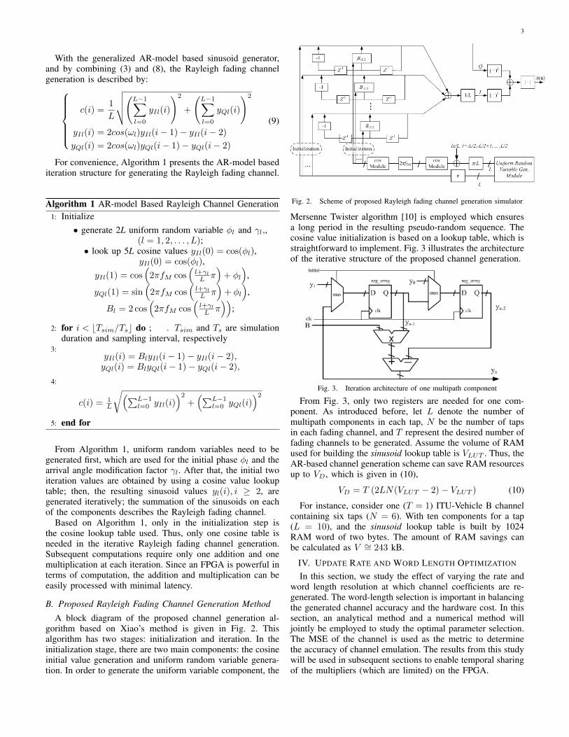
A block diagram of the proposed channel generation al-gorithm based on Xiao’s method is given in Fig. 2. Thisalgorithm has two stages: initialization and iteration. In theinitialization stage, there are two main components: the cosineinitial value generation and uniform random variable genera-tion. In order to generate the uniform variable component, the
Fig. 2. Scheme of proposed Rayleigh fading channel generation simulator
Mersenne Twister algorithm [10] is employed which ensuresa long period in the resulting pseudo-random sequence. Thecosine value initialization is based on a lookup table, which isstraightforward to implement. Fig. 3 illustrates the architectureof the iterative structure of the proposed channel generation.
Fig. 3. Iteration architecture of one multipath component
From Fig. 3, only two registers are needed for one com-ponent. As introduced before, let L denote the number ofmultipath components in each tap, N be the number of tapsin each fading channel, and T represent the desired number offading channels to be generated. Assume the volume of RAMused for building the sinusoid lookup table is VLUT . Thus, theAR-based channel generation scheme can save RAM resourcesup to VD, which is given in (10),
VD = T (2LN(VLUT − 2)− VLUT ) (10)
For instance, consider one (T = 1) ITU-Vehicle B channelcontaining six taps (N = 6). With ten components for a tap(L = 10), and the sinusoid lookup table is built by 1024RAM word of two bytes. The amount of RAM savings canbe calculated as V ∼= 243 kB.
IV. UPDATE RATE AND WORD LENGTH OPTIMIZATION
In this section, we study the effect of varying the rate andword length resolution at which channel coefficients are re-generated. The word-length selection is important in balancingthe generated channel accuracy and the hardware cost. In thissection, an analytical method and a numerical method willjointly be employed to study the optimal parameter selection.The MSE of the channel is used as the metric to determinethe accuracy of channel emulation. The results from this studywill be used in subsequent sections to enable temporal sharingof the multipliers (which are limited) on the FPGA.

4
Fig. 4. Channel update rate effect and word length optimization illustration
A. Channel Update Rate Emulation with Analytical Method
Let TW denote the time duration between updates, whichshould be smaller than the coherence time of the channel.Hence, we select the channel update interval TW to be smallerthan the inverse of the maximum Doppler shift 1/fM . Thisassumption is reasonable because the channel output loss willbecome extremely large when TW approaches 1/fM .
We first model one multipath component, which we laterleverage to determine the scalability of a network emulator.For simplicity, consider a quarter of the sinusoid period foranalysis, since a quarter period contains all the curvatureinformation for the entire sinusoid. Let I denote the numberof the update points in 1/4 the period of a sinusoid in onecomponent (Fig. 4). From this figure, I can be determined asI = b1/4fMTW c.
The sinusoid at the i-th time instant is c(i) =cos 2πifMTW , i = 0, 1, 2, . . . , I . The difference between twoadjacent points can be calculated by:
∆c(i) = c(i)− c(i+ 1)
= 2 sin(2πifMTW + πfMTW ) sin(πfMTW )(11)
The channel error, e, caused by discretely updating overthe 1/4 period range can be calculated by summing up all thedifferences (∆c(i), i = 0, 1, . . . , I − 1) and is given by
e =
I−1∑i=0
1
2∆c(i)TW
= sin(πfMTW )
I−1∑i=0
sin(2πfMTW (i+1
2))TW
∼=1
2πfMsin(πfMTW ) ∼=
TW8πI
sin(4πI) (12)
The longer update interval TW induces a larger error causedby discrete channel updates. Further, for a fixed Doppler shift,a smaller TW allows a larger I , decreasing the error.
B. Channel Update Rate Discussion with Numerical Method
To generate a tap of a fading channel, multiple componentswill be added to constitute the in-phase and quadrature compo-nents of a fading channel. Then, the square root of the in-phaseand quadrature components will be calculated as the finalfading channel output. In the process of calculating the squareroot, the phase information will be lost, in which case, theanalytical method above does not work. Thus, the numerical
Fig. 5. Error of channel caused by discrete update
method is employed which considers the square root of in-phase and quadrature components. During the observation time∆t, the discretely-updated Rayleigh fading channel is given as:
c′(t) = A
P−1∑p=0
L−1∑l=0
cos(2πfM (cosαl)pTW + πl)
· [U(t− pTW )− U(t− (p+ 1)TW )],(13)
where P accounts for the fading channel updates within thetime duration of ∆t, P = b∆t/TW c.
To measure the approximation error of the discretely up-dated fading channel, the mean square of error (MSE) e2
∆t iscalculated as,
e2∆t =
1
∆t
∫ ∆t
0
|c(t)− c′(t)|2dt
=1
∆t
P−1∑p=0
∫ (p−1)TW
pTW
|L−1∑l=0
cos(2πfM (cosαl)pTW + πl)
−L−1∑l=0
cos(2πfM (cosαl)t+ πl)|2dt
(14)Fig. 5 presents the channel distortion caused by the discrete
update interval. The maximum Doppler frequency for thegenerated Rayleigh fading channel is 500 Hz. The minimumchannel status update interval is 0.1 ms and the maximuminterval is 10 ms. From Fig. 5, the channel errors increase ina nearly linear manner as the update interval increases, whichagrees with the earlier analytical result.
C. Word-Length Effect on SOS Based Channel GenerationBesides the channel update rate consideration, the word
length of each point in the fading channel generation willaffect the hardware resources consumed. In this section, wefirst discuss the approximation error for a quantized cosinewaveform at a single carrier. We assume the cosine waveis quantized by M levels, M = 2P , where P is a positiveinteger. Thus, the distance between two quantization levels is∆d = 1/M , which is illustrated in Fig. 4. From Fig. 4, withinthe range [0, 0.25], the quantized cosine waveform at the m-thlevel is given by
x(m) = 1/2π arccos(m∆t),m = 0, 1, 2, . . . ,M (15)
After the uniform quantization, the corresponding error causedby the limited resolution can be calculated. The difference
5
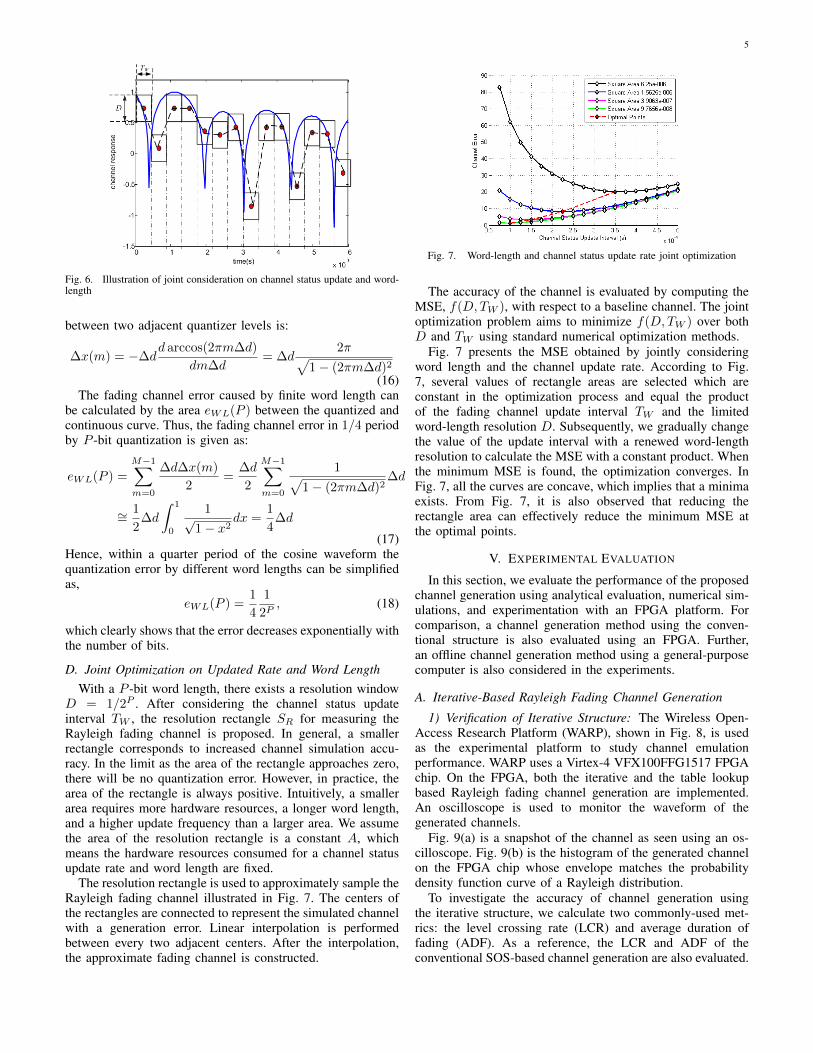
Fig. 6. Illustration of joint consideration on channel status update and word-length
between two adjacent quantizer levels is:
∆x(m) = −∆dd arccos(2πm∆d)
dm∆d= ∆d
2π√1− (2πm∆d)2
(16)The fading channel error caused by finite word length can
be calculated by the area eWL(P ) between the quantized andcontinuous curve. Thus, the fading channel error in 1/4 periodby P -bit quantization is given as:
eWL(P ) =
M−1∑m=0
∆d∆x(m)
2=
∆d
2
M−1∑m=0
1√1− (2πm∆d)2
∆d
∼=1
2∆d
∫ 1
0
1√1− x2
dx =1
4∆d
(17)Hence, within a quarter period of the cosine waveform thequantization error by different word lengths can be simplifiedas,
eWL(P ) =1
4
1
2P, (18)
which clearly shows that the error decreases exponentially withthe number of bits.
D. Joint Optimization on Updated Rate and Word LengthWith a P -bit word length, there exists a resolution window
D = 1/2P . After considering the channel status updateinterval TW , the resolution rectangle SR for measuring theRayleigh fading channel is proposed. In general, a smallerrectangle corresponds to increased channel simulation accu-racy. In the limit as the area of the rectangle approaches zero,there will be no quantization error. However, in practice, thearea of the rectangle is always positive. Intuitively, a smallerarea requires more hardware resources, a longer word length,and a higher update frequency than a larger area. We assumethe area of the resolution rectangle is a constant A, whichmeans the hardware resources consumed for a channel statusupdate rate and word length are fixed.
The resolution rectangle is used to approximately sample theRayleigh fading channel illustrated in Fig. 7. The centers ofthe rectangles are connected to represent the simulated channelwith a generation error. Linear interpolation is performedbetween every two adjacent centers. After the interpolation,the approximate fading channel is constructed.
Fig. 7. Word-length and channel status update rate joint optimization
The accuracy of the channel is evaluated by computing theMSE, f(D,TW ), with respect to a baseline channel. The jointoptimization problem aims to minimize f(D,TW ) over bothD and TW using standard numerical optimization methods.
Fig. 7 presents the MSE obtained by jointly consideringword length and the channel update rate. According to Fig.7, several values of rectangle areas are selected which areconstant in the optimization process and equal the productof the fading channel update interval TW and the limitedword-length resolution D. Subsequently, we gradually changethe value of the update interval with a renewed word-lengthresolution to calculate the MSE with a constant product. Whenthe minimum MSE is found, the optimization converges. InFig. 7, all the curves are concave, which implies that a minimaexists. From Fig. 7, it is also observed that reducing therectangle area can effectively reduce the minimum MSE atthe optimal points.
V. EXPERIMENTAL EVALUATION
In this section, we evaluate the performance of the proposedchannel generation using analytical evaluation, numerical sim-ulations, and experimentation with an FPGA platform. Forcomparison, a channel generation method using the conven-tional structure is also evaluated using an FPGA. Further,an offline channel generation method using a general-purposecomputer is also considered in the experiments.
A. Iterative-Based Rayleigh Fading Channel Generation
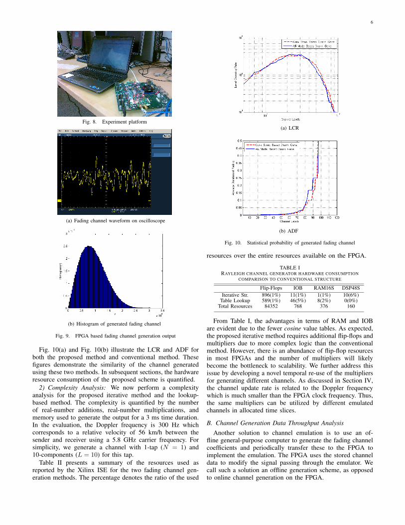
1) Verification of Iterative Structure: The Wireless Open-Access Research Platform (WARP), shown in Fig. 8, is usedas the experimental platform to study channel emulationperformance. WARP uses a Virtex-4 VFX100FFG1517 FPGAchip. On the FPGA, both the iterative and the table lookupbased Rayleigh fading channel generation are implemented.An oscilloscope is used to monitor the waveform of thegenerated channels.
Fig. 9(a) is a snapshot of the channel as seen using an os-cilloscope. Fig. 9(b) is the histogram of the generated channelon the FPGA chip whose envelope matches the probabilitydensity function curve of a Rayleigh distribution.
To investigate the accuracy of channel generation usingthe iterative structure, we calculate two commonly-used met-rics: the level crossing rate (LCR) and average duration offading (ADF). As a reference, the LCR and ADF of theconventional SOS-based channel generation are also evaluated.
6
Fig. 8. Experiment platform
(a) Fading channel waveform on oscilloscope
(b) Histogram of generated fading channel
Fig. 9. FPGA based fading channel generation output
Fig. 10(a) and Fig. 10(b) illustrate the LCR and ADF forboth the proposed method and conventional method. Thesefigures demonstrate the similarity of the channel generatedusing these two methods. In subsequent sections, the hardwareresource consumption of the proposed scheme is quantified.
2) Complexity Analysis: We now perform a complexityanalysis for the proposed iterative method and the lookup-based method. The complexity is quantified by the numberof real-number additions, real-number multiplications, andmemory used to generate the output for a 3 ms time duration.In the evaluation, the Doppler frequency is 300 Hz whichcorresponds to a relative velocity of 56 km/h between thesender and receiver using a 5.8 GHz carrier frequency. Forsimplicity, we generate a channel with 1-tap (N = 1) and10-components (L = 10) for this tap.
Table II presents a summary of the resources used asreported by the Xilinx ISE for the two fading channel gen-eration methods. The percentage denotes the ratio of the used
(a) LCR
(b) ADF
Fig. 10. Statistical probability of generated fading channel
resources over the entire resources available on the FPGA.
TABLE IRAYLEIGH CHANNEL GENERATOR HARDWARE CONSUMPTION
COMPARISON TO CONVENTIONAL STRUCTURE
Flip-Flops IOB RAM16S DSP48SIterative Str. 896(1%) 11(1%) 1(1%) 10(6%)
Table Lookup 589(1%) 46(5%) 8(2%) 0(0%)Total Resources 84352 768 376 160
From Table I, the advantages in terms of RAM and IOBare evident due to the fewer cosine value tables. As expected,the proposed iterative method requires additional flip-flops andmultipliers due to more complex logic than the conventionalmethod. However, there is an abundance of flip-flop resourcesin most FPGAs and the number of multipliers will likelybecome the bottleneck to scalability. We further address thisissue by developing a novel temporal re-use of the multipliersfor generating different channels. As discussed in Section IV,the channel update rate is related to the Doppler frequencywhich is much smaller than the FPGA clock frequency. Thus,the same multipliers can be utilized by different emulatedchannels in allocated time slices.
B. Channel Generation Data Throughput AnalysisAnother solution to channel emulation is to use an of-
fline general-purpose computer to generate the fading channelcoefficients and periodically transfer these to the FPGA toimplement the emulation. The FPGA uses the stored channeldata to modify the signal passing through the emulator. Wecall such a solution an offline generation scheme, as opposedto online channel generation on the FPGA.

7
0 0.2 0.4 0.6 0.8 10
0.01
0.02
Sim
ulat
ion
Tim
e(s)
Rayleigh Fading Channel Data Length(s)0 0.2 0.4 0.6 0.8 1
0
10
20
Fad
ing
Cha
nnel
Dat
a R
ate(
Mbi
ts/s
)
Fig. 11. Rayleigh fading channel offline generation rate
In the experiment, the PC used for generating the channelis equipped with an Intel i3 CPU at 2.26 GHz with 4 GBof RAM. Fig. 11 demonstrates the experimental results. Thedashed curve represents the time consumed for generatinga certain duration of the fading channel. The green solidcurve denotes the corresponding channel parameter data rate,which represents the effective rate at which data needs to betransferred between the PC and the FPGA to enable emulation.From Fig. 11, we see that this rate is on the order of 20 Mbits/sfor each tap.
From the result of experiments on the Virtex-4 VFX100, theFPGA can generate up to 3.3 Gbits/s of channel coefficients foremulation. Clearly, the proposed channel generation schemebased on an FPGA outperforms the PC-based solution interms of channel data throughput. Further, the offline PC-basedgeneration requires additional RAM and buffers, especially forlarge-scale networks. On the other hand, the PC-based solutionwould reduce the computation burden on the FPGA, whichcould be useful in certain scenarios.
C. Performance Across Update Rates and Word LengthsIn Section IV, we analytically derived the expression for
the MSE caused by a finite word length and update rate.In this section, the accuracy of the two expressions will beverified. The x-axis values in Fig. 12(a) denote the updateinterval which is measured in terms of 10 times the slice ofthe FPGA chip. The stars in Fig. 12(a) are the MSE values atdifferent update intervals. The bold line represents the optimallinear fit to the data. We can see that the bold line agrees withMSE prediction in (12). To analyze the effect of word lengthon the MSE of the generated channel, we change the bit widthin the process of generating fading channel from 8 to 16 bits.Fig. 12(b) presents the normalized MSE (normalized to theperformance with 16 bits) for the different bit widths (8 to16 bits). From Fig. 12(b), the MSE decreases when the wordsize increases, which agrees with our intuition that a largerword size results in a higher accuracy. The stars mark theMSE at every word size, and the bold line represents the bestexponential fit, matching the result in (18).
D. Accuracy of Generated Fading ChannelIn this subsection, the accuracy of the generated channel is
measured using the resulting BER for a particular modulationscheme. In the experiments, a simulated channel generated inMATLAB (using real-valued coefficients with double preci-sion) is taken as one reference. Furthermore, the performance
4 6 8 10 12 14 16 18 200.5
0.6
0.7
0.8
0.9
1
1.1
Number of update time intervel (10ns)
Nor
mal
ized
MS
E
(a) MSE versus update interval
8 9 10 11 12 13 14 15
0.4
0.5
0.6
0.7
0.8
0.9
1
1.1
1.2
1.3
Word Length(Bits)
MS
E(b) MSE versus word length
Fig. 12. MSE of generated fading channel on FPGA
Fig. 13. 16QAM BER curves over generated fading channel
using a commercial fading channel emulator, the Azimuth400MX, is also shown.
Using the same iterative algorithm implemented on theFPGA, we employ MATLAB to generate the channel. Thesame parameter settings are used in the two implementationplatforms. Specifically, ITU-Vehicle B fading channels aregenerated which each contain six taps. The relative delaybetween the taps are [0 100 200 300 500 700] in ns andthe relative energy ratios are [0 -3.6 -7.2 -10.8 - 18 -25.2]in dB. Signals using 16-QAM modulation are passed throughthe two fading channels. For simplicity, we do not considerchannel estimation and equalization at the receiver. Fig. 13shows that the BER over the fading channel from the twoplatforms behave in a similar manner.
Then, we compare the packet error rate (PER) of the

8
0 5 10 15 20
10−1
100
SNR(dB)
PE
R
PER over Azimuth emulatorPER over proposed emulator
Fig. 14. QPSK PER curves on WARP and Azimuth emulator
proposed emulator with the existing commercial channelemulator-Azimuth 400MX. In the experiments, two WARPboards are used as the transmitter (TX) and receiver (RX).
In the experiment, two kinds of trials are performed. Inthe first trial, the WARP-TX generates QPSK signals whichare passed through the fading channel and also generated onthe WARP-TX board. The resulting output signals are sent tothe WARP-RX board. In the second trial, the generated QPSKsignals from the WARP-TX board is connected to the Azimuthemulator via cable. The output signal from the emulator is sentto the WARP-RX board. In the two trials, the packet size is1.5 kB and uses an 802.11a physical layer. Fig. 14 presentsthe variation of the PER curves versus SNR. From this figure,it is clear that the the PER of the two emulators, Azimuth andthe proposed emulator, closely agree with one another.
VI. NETWORK EMULATION SCALABILITY
Large-scale network emulation using off-the-shelf ap-proaches requires significantly large hardware resources andis consequently very expensive. In this section, we discuss thescalability of the proposed network emulation framework.
A. Factors Allowing Greater Scalability
Two key novelties in the proposed emulation approachallows for better scalability of the networks. First, the proposediterative structure results in significant memory savings forthe FPGA. Second, update rate optimization is performed andcoupled with a time-sharing architecture for multipliers toensure better scaling.
Contribution: Scalability by Saving Memory. Accordingto the experimental results, one tap of a Rayleigh fading chan-nel consumes one RAMB16. The total memory resources ofthe aforementioned FPGA chip equals 376 units of RAMB16s.Therefore, using the proposed iterative structure, we cansupport the generation of 60 ITU-Vehicle B channels.
Contribution: Scalability by Update Rate Optimization.From the experimental results, we recognize that the hardwarebottleneck for the emulator, in general, is the number ofmultipliers available. As discussed in Section IV, the fadingchannel coefficients need not be updated at the clock rate.Assume that there are 20 updates during each time durationof one over the maximum Doppler frequency (1/2πfM ). FromFig. 5, it can be seen that using 10 update points per periodcan guarantee an MSE of less than 10−4. With high levelsof mobility (1000 Hz Doppler), the corresponding update rateis 20, 000 points/second. According to our measurements, the
Fig. 15. Architecture of multiplier time division multiplexing
highest clock rate can reach 9600 ps which corresponds tothe frequency of 104, 170, 000 Hz. Therefore, the numberof multipliers is no longer the bottleneck to increasing thenetwork emulation scale.
Fig. 15 presents the architecture of multiplier temporal reusefor the in-phase component. Each color bar represents differenttime slices allocated to generate the fading channel on eachmultipath component. From the architecture, to implement thetemporal reuse on one multiplier, two multiplexers and fourregisters are needed. Also, one encoder is taken as the controlcircuit built with basic logic gates. In the condition of 16 bitsper variable, the implementation of the in-phase componentsfor four components require 32 of the 4-input LUTs and64 flip-flops. Indeed, more than four components can beimplemented by multiplexing one multiplier. To guarantee lowlatency, one multiplier is used for 20 components.
B. Network Scale Analysis
We now estimate the achievable scale on the selected FPGAchip: Virtex-4 VFX100. With the same update rate, the topof Table II shows the consumption of RAM, flip-flops, andLUTs versus word lengths for one tap. The bottom of Table IIpresents the expenditure versus taps with a fixed word length.From the two figures, we can intuitively see the requiredhardware resources are small compared with the total.
TABLE IIHARDWARE RESOURCE CONSUMPTION
Word Length 8 Bits 10 Bits 12 Bits 14 Bits 16 Bits Total Resource
RAMB16s 1 1 1 1 1 376Flip-Flops 602 700 792 896 994 84352
LUTs 618 712 807 901 995 84352
Taps 1 2 3 4 5 Total Resource
RAMB16s 1 2 3 4 5 376Flip-Flops 994 1988 2982 3976 4970 84352
LUTs 995 1990 2985 3980 4975 84352
We now analytically compute the number of channels thatcan be emulated. Let variables W, L, N , and T denote,respectively, the word length, the number of multipath com-ponents per tap, number of taps per channel, and the numberof channels. Using simple enumeration, it can be shown thatthe total RAM required equals TN . We also calculate thenumber of flip-flops and LUTs required for several differentvalues of the parameters. Based on these values, the numberof flip-flops required is of the form TN(2LW − 13L+ 324).Including the number of flip-flops required for the controller

9
circuit to enable temporal multiplexing of the multipliers, thetotal number of flip-flops required is of the form TN(2LW −13L + 324) +
⌈TNL
20
⌉20W . Similarly, it can be shown that
the total number of LUTs needed to support this networkequals TN(2LW + 4L + 161) +
⌈TNL
20
⌉40W . The selected
Virtex-4 FPGA has 376 RAMB16s, 84352 flip-flops, and84352 LUTs. Thus, the selected network and channel param-eters can be emulated if the following conditions are satisfied:
TN ≤ 376
TN(2LW − 13L+ 324) +
⌈TNL
20
⌉20W ≤ 84352
TN(2LW + 4L+ 161) +
⌈TNL
20
⌉40W ≤ 84352
(19)Based on the derived constraint equations, the maximum
wireless network scale can be estimated. Assume the wordlength is 16 bits (W=16), and each tap consists of 10 compo-nents (L=10). According to (19), the maximum product of Tand N is 66. Thus, for instance, 11 links of an ITU-VehicleB channel can be emulated. If the word length is reducedto 12 bits and we use 8 components per tap, the achievablenetworks scale is 24 links for a single FPGA.
VII. RELATED WORK
Due to their extensive use and low price, FPGAs are oftenselected as the hardware platform for fast-fading channelemulation [11]–[15]. Rao et al. [12] developed an architecturefor VLSI implementation of mobile wireless communicationchannels based on Xiao’s improvement [6] to the Jakes’ model.Fard et al. [14] and Nasr [16] designed channel emulatorsbased on the principle of filtering white Gaussian randomvariables. All these works consider the emulation of a singlelink and do not focus on the scalability of their solutions noron the optimization of hardware resources.
Eslami [17] presented a design and implementation of afrequency-based, scalable channel emulator which is basedon an FFT/IFFT fading channel generation method. The FFTwas implemented using the CORDIC algorithm. Such a fadingchannel emulation solution has several drawbacks. First, thegenerated channel data length is fixed, which is determinedby the size of the FFT. Thus, the scalability of the emulatoris limited in terms of data generation flexibility. Second,the CORDIC algorithm can save hardware resources, but thecomputational speed is relatively slow. Third, even thoughEslami saved hardware resources compared to the other FIRfilter based emulator, the number of multipliers required isstill large. Buscemi and Sass [18] described the feasibilityof a scalable wireless channel emulator based on a 64-FPGA cluster. Clearly, the price of the system would precludewidespread usability. Scalable network emulator design is alsoaddressed in Koizumi et al. [19] and Zheng and Ni [20].However, the focus is on the general structure of the emulatorand no details on the link-level channels are provided.
VIII. CONCLUSION
This paper discussed the design of a scalable wirelessnetwork emulator by analytically and experimentally studyingthe tradeoff in channel accuracy and implementation resource
consumption. To do so, we presented and analyzed two keytechniques: an iterative-based method for generating Rayleighfading channels and a joint optimization of the update rate andword length. Extensive experimentation was performed andcompared against both idealized models generated by a sim-ulator and a high-fidelity commercial emulator. We leveragedour single channel analysis to understand the implementationresources necessary to build a large-scale network emulator.Using our methods which also included a multiplexing methodfor reducing the multiplier usage, a single FPGA could emu-late up to 24 vehicular channels in real-time.
REFERENCES
[1] “Azimuth ACE - MIMO Channel Emulator for Broadband Wireless Test-ing,” http://www.azimuthsystems.com/platforms channel mx.htm, Jul2012.
[2] “The Network Simulator NS-2,” http://www.isi.edu/nsnam/ns/.[3] K. C. B. et al., “FPGA-based channel simulator for a wireless network
emulator,” in Proc. of IEEE VTC, Barcelona, Spain, Apr 2009.[4] R. Clarke, “A statistical theory of mobile-radio perception,” Bell Syst.
Tech. J., vol. 47, pp. 957 –1000, 1968.[5] W. Jake, Microwave Mobile Communication. Piscataway, NJ: Wiley-
IEEE Press, 1974.[6] C. X. et al., “Novel sum-of-sinusoids simulation models for rayleigh
and rician fading channels,” Wireless Communications, IEEE Tran. on,vol. 5, no. 12, pp. 3667 –3679, Dec 2006.
[7] J. X. et al., “Fpga-accelerated real-time volume rendering for 3d medicalimage,” in Biomedical Engineering and Informatics (BMEI), 2010 3rdInt. Conf. on, vol. 1, Oct 2010, pp. 273 –276.
[8] G. W. et al., “A high performance and memory efficient lu decomposeron fpgas,” Computers, IEEE Tran. on, vol. 61, no. 3, pp. 366 –378, Mar2012.
[9] A. Alimohammad and B. Cockburn, “Modeling and hardware imple-mentation aspects of fading channel simulators,” Vehicular Technology,IEEE Tran. on, vol. 57, no. 4, pp. 2055 –2069, Jul 2008.
[10] M. Matsumoto and T. Nishimura, “Mersenne twister: a 623-dimensionally equidistributed uniform pseudo-random number genera-tor,” ACM Trans. Model Comput. Simul., vol. 8, no. 1, pp. 3 – 30, May1998.
[11] A. e. a. Alimohammad, “An improved sos-based fading channel emula-tor,” in Vehicular Technology Conf., 2007. VTC-2007 Fall. 2007 IEEE66th, 30 2007-Oct. 3 2007, pp. 931 –935.
[12] G. Rao, R. Bhattacharjee, and S. Nandi, “Vlsi architecture for rayleighand rician fading generators,” in TENCON 2004. 2004 IEEE Region 10Conf., vol. C, Nov 2004, pp. 121 – 124 Vol. 3.
[13] K. e. a. Borries, “FPGA-based channel simulator for a wireless networkemulator,” in Vehicular Technology Conf., 2009. VTC Spring 2009. IEEE69th, Apr 2009, pp. 1 –5.
[14] S. e. a. Fard, “A single fpga filter-based multipath fading emulator,” inGlobal Telecommunications Conf., 2009. GLOBECOM 2009. IEEE, 302009-Dec. 4 2009, pp. 1 –5.
[15] J.-K. H. et al., “Fast fpga prototyping of a multipath fading channelemulator via high-level design,” in Communications and InformationTechnologies, 2007. ISCIT ’07. Int. Symposium on, Oct 2007, pp. 168–171.
[16] O. Nasr and B. Daneshrad, “Design and fpga implementation anaccurate real time 3x4 mimo channel emulator,” in Signals, Systemsand Computers, 2009 Conf. Record of the Forty-Third Asilomar Conf.on, Nov 2009, pp. 764 –768.
[17] H. e. a. Eslami, “Design and implementation of a scalable channelemulator for wideband mimo systems,” Vehicular Technology, IEEETran. on, vol. 58, no. 9, pp. 4698 –4709, Nov 2009.
[18] S. Buscemi and R. Sass, “Design of a scalable digital wireless channelemulator for networking radios,” in Military Communications Conf.,2011 - MILCOM 2011, Nov 2011, pp. 1858 –1863.
[19] M. e. a. Koizumi, “Design and implementation of scalable distributedwireless network emulator for high-speed mobility,” in InformationNetworking (ICOIN), 2012 Int. Conf. on, Feb 2012, pp. 302 –307.
[20] P. Zheng and L. Ni, “Empower: a network emulator for wireline andwireless networks,” in INFOCOM 2003. Twenty-Second Annual JointConf. of the IEEE Computer and Communications. IEEE Societies,vol. 3, Mar.-3 Apr 2003, pp. 1933 – 1942 vol.3.