TouchMover: Actuated 3D Touchscreen with Haptic Feedback · sensed and actuated in up to three...
10
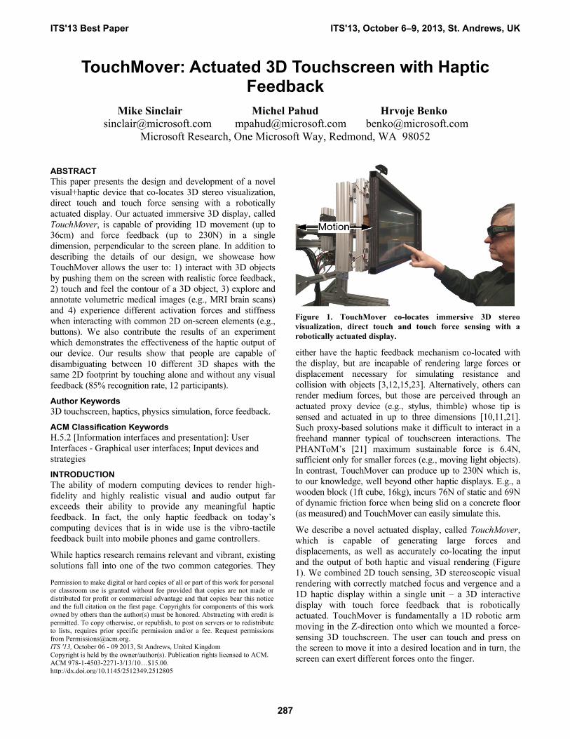
TouchMover: Actuated 3D Touchscreen with Haptic Feedback Mike Sinclair Michel Pahud Hrvoje Benko [email protected] [email protected] [email protected] Microsoft Research, One Microsoft Way, Redmond, WA 98052 ABSTRACT This paper presents the design and development of a novel visual+haptic device that co-locates 3D stereo visualization, direct touch and touch force sensing with a robotically actuated display. Our actuated immersive 3D display, called TouchMover, is capable of providing 1D movement (up to 36cm) and force feedback (up to 230N) in a single dimension, perpendicular to the screen plane. In addition to describing the details of our design, we showcase how TouchMover allows the user to: 1) interact with 3D objects by pushing them on the screen with realistic force feedback, 2) touch and feel the contour of a 3D object, 3) explore and annotate volumetric medical images (e.g., MRI brain scans) and 4) experience different activation forces and stiffness when interacting with common 2D on-screen elements (e.g., buttons). We also contribute the results of an experiment which demonstrates the effectiveness of the haptic output of our device. Our results show that people are capable of disambiguating between 10 different 3D shapes with the same 2D footprint by touching alone and without any visual feedback (85% recognition rate, 12 participants). Author Keywords 3D touchscreen, haptics, physics simulation, force feedback. ACM Classification Keywords H.5.2 [Information interfaces and presentation]: User Interfaces - Graphical user interfaces; Input devices and strategies INTRODUCTION The ability of modern computing devices to render high- fidelity and highly realistic visual and audio output far exceeds their ability to provide any meaningful haptic feedback. In fact, the only haptic feedback on today’s computing devices that is in wide use is the vibro-tactile feedback built into mobile phones and game controllers. While haptics research remains relevant and vibrant, existing solutions fall into one of the two common categories. They either have the haptic feedback mechanism co-located with the display, but are incapable of rendering large forces or displacement necessary for simulating resistance and collision with objects [3,12,15,23]. Alternatively, others can render medium forces, but those are perceived through an actuated proxy device (e.g., stylus, thimble) whose tip is sensed and actuated in up to three dimensions [10,11,21]. Such proxy-based solutions make it difficult to interact in a freehand manner typical of touchscreen interactions. The PHANToM’s [21] maximum sustainable force is 6.4N, sufficient only for smaller forces (e.g., moving light objects). In contrast, TouchMover can produce up to 230N which is, to our knowledge, well beyond other haptic displays. E.g., a wooden block (1ft cube, 16kg), incurs 76N of static and 69N of dynamic friction force when being slid on a concrete floor (as measured) and TouchMover can easily simulate this. We describe a novel actuated display, called TouchMover, which is capable of generating large forces and displacements, as well as accurately co-locating the input and the output of both haptic and visual rendering (Figure 1). We combined 2D touch sensing, 3D stereoscopic visual rendering with correctly matched focus and vergence and a 1D haptic display within a single unit – a 3D interactive display with touch force feedback that is robotically actuated. TouchMover is fundamentally a 1D robotic arm moving in the Z-direction onto which we mounted a force- sensing 3D touchscreen. The user can touch and press on the screen to move it into a desired location and in turn, the screen can exert different forces onto the finger. Permission to make digital or hard copies of all or part of this work for personal or classroom use is granted without fee provided that copies are not made or distributed for profit or commercial advantage and that copies bear this notice and the full citation on the first page. Copyrights for components of this work owned by others than the author(s) must be honored. Abstracting with credit is permitted. To copy otherwise, or republish, to post on servers or to redistribute to lists, requires prior specific permission and/or a fee. Request permissions from [email protected]. ITS '13, October 06 - 09 2013, St Andrews, United Kingdom Copyright is held by the owner/author(s). Publication rights licensed to ACM. ACM 978-1-4503-2271-3/13/10…$15.00. http://dx.doi.org/10.1145/2512349.2512805 Figure 1. TouchMover co-locates immersive 3D stereo visualization, direct touch and touch force sensing with a robotically actuated display. ITS'13 Best Paper ITS'13, October 6–9, 2013, St. Andrews, UK 287
Transcript of TouchMover: Actuated 3D Touchscreen with Haptic Feedback · sensed and actuated in up to three...
TouchMover: Actuated 3D Touchscreen with Haptic Feedback
Mike Sinclair Michel Pahud Hrvoje Benko
[email protected] [email protected] [email protected]
Microsoft Research, One Microsoft Way, Redmond, WA 98052
ABSTRACT
This paper presents the design and development of a novel
visual+haptic device that co-locates 3D stereo visualization,
direct touch and touch force sensing with a robotically
actuated display. Our actuated immersive 3D display, called
TouchMover, is capable of providing 1D movement (up to
36cm) and force feedback (up to 230N) in a single
dimension, perpendicular to the screen plane. In addition to
describing the details of our design, we showcase how
TouchMover allows the user to: 1) interact with 3D objects
by pushing them on the screen with realistic force feedback,
2) touch and feel the contour of a 3D object, 3) explore and
annotate volumetric medical images (e.g., MRI brain scans)
and 4) experience different activation forces and stiffness
when interacting with common 2D on-screen elements (e.g.,
buttons). We also contribute the results of an experiment
which demonstrates the effectiveness of the haptic output of
our device. Our results show that people are capable of
disambiguating between 10 different 3D shapes with the
same 2D footprint by touching alone and without any visual
feedback (85% recognition rate, 12 participants).
Author Keywords
3D touchscreen, haptics, physics simulation, force feedback.
ACM Classification Keywords
H.5.2 [Information interfaces and presentation]: User
Interfaces - Graphical user interfaces; Input devices and
strategies
INTRODUCTION
The ability of modern computing devices to render high-
fidelity and highly realistic visual and audio output far
exceeds their ability to provide any meaningful haptic
feedback. In fact, the only haptic feedback on today’s
computing devices that is in wide use is the vibro-tactile
feedback built into mobile phones and game controllers.
While haptics research remains relevant and vibrant, existing
solutions fall into one of the two common categories. They
either have the haptic feedback mechanism co-located with
the display, but are incapable of rendering large forces or
displacement necessary for simulating resistance and
collision with objects [3,12,15,23]. Alternatively, others can
render medium forces, but those are perceived through an
actuated proxy device (e.g., stylus, thimble) whose tip is
sensed and actuated in up to three dimensions [10,11,21].
Such proxy-based solutions make it difficult to interact in a
freehand manner typical of touchscreen interactions. The
PHANToM’s [21] maximum sustainable force is 6.4N,
sufficient only for smaller forces (e.g., moving light objects).
In contrast, TouchMover can produce up to 230N which is,
to our knowledge, well beyond other haptic displays. E.g., a
wooden block (1ft cube, 16kg), incurs 76N of static and 69N
of dynamic friction force when being slid on a concrete floor
(as measured) and TouchMover can easily simulate this.
We describe a novel actuated display, called TouchMover,
which is capable of generating large forces and
displacements, as well as accurately co-locating the input
and the output of both haptic and visual rendering (Figure
1). We combined 2D touch sensing, 3D stereoscopic visual
rendering with correctly matched focus and vergence and a
1D haptic display within a single unit – a 3D interactive
display with touch force feedback that is robotically
actuated. TouchMover is fundamentally a 1D robotic arm
moving in the Z-direction onto which we mounted a force-
sensing 3D touchscreen. The user can touch and press on
the screen to move it into a desired location and in turn, the
screen can exert different forces onto the finger.
Permission to make digital or hard copies of all or part of this work for personal
or classroom use is granted without fee provided that copies are not made or
distributed for profit or commercial advantage and that copies bear this notice
and the full citation on the first page. Copyrights for components of this work
owned by others than the author(s) must be honored. Abstracting with credit is
permitted. To copy otherwise, or republish, to post on servers or to redistribute
to lists, requires prior specific permission and/or a fee. Request permissions
from [email protected].
ITS '13, October 06 - 09 2013, St Andrews, United Kingdom
Copyright is held by the owner/author(s). Publication rights licensed to ACM.
ACM 978-1-4503-2271-3/13/10…$15.00.
http://dx.doi.org/10.1145/2512349.2512805
Figure 1. TouchMover co-locates immersive 3D stereo
visualization, direct touch and touch force sensing with a
robotically actuated display.
ITS'13 Best Paper ITS'13, October 6–9, 2013, St. Andrews, UK
287
This unique combination enables the user to maintain all
the benefits of multi-touch touchscreens enhanced with the
ability to move that screen in space and also simultaneously
receive high-fidelity haptic feedback. It also has an added
benefit when interacting with 3D stereo views: since our
stereo convergence plane is set to be exactly at the screen
depth, objects being touched are rendered with zero
parallax (i.e., the depth of the screen plane, the fingertip,
and the virtual object match exactly). Consequently, our
design eliminates 3D touch selection problems [28] present
when objects being selected are rendered with stereo
parallax.
In particular, our work makes the following four
contributions: 1) the design and implementation details of
the TouchMover actuated display, 2) a solution for
measurement of finger force separately from the force
caused by the screen’s inertia which enables correct force
feedback while the screen is in motion; 3) four application
prototypes which showcase different interaction scenarios
with our device; and 4) experimental results showing that
people are capable of disambiguating ten different 3D
shapes on our device purely via touch-based haptic
feedback and without any visual feedback. These
contributions demonstrate the potential of TouchMover to
deliver high-fidelity haptic and visual feedback and create
novel immersive experiences.
Given its current size and power requirements,
TouchMover is primarily a research tool; designed to help
us and inspire others to explore scenarios combining touch,
3D vision, visual accommodation, and 1D haptics.
RELATED WORK
Providing tightly coupled haptic and visual feedback has
been shown to improve the realism and immersion in
virtual environments [6]. To our knowledge, TouchMover
is the first solution which combines large force haptics, 3D
stereo rendering and a freehand direct touch interface.
Haptics is an active research area and thorough review of
related work is beyond the scope of this paper. For a more
detailed (albeit dated) review of haptics (in connection with
virtual reality) we refer the reader to [8,9]. We focus our
review only on closely related work: 1) solutions that
provide large force haptic feedback to the user’s fingertip,
2) solutions which couple haptics and touchscreens, and 3)
solutions which couple touch and 3D stereoscopic viewing.
A large portion of haptic research involves the use of
impedance-type active haptic interfaces like SensAble’s
Phantom1 and Novint’s Falcon2 plus a number of 2D+
cable-driven force feedback devices (e.g., [16,29]). Such
haptic devices employ three or more actuators, orthogonally
terminating at a single end effector point (usually a stylus
1 http://www.sensable.com/haptic-phantom-desktop.htm
2 http://www.novint.com/index.php/novintfalcon
tip). Kuchenbecker et al [18] installed a finger thimble at
the end effector location of a Phantom device with fixed
isolation compliance to engage the sensitive fingertip only
when in contact with a virtual 3D surface. This was a
haptics-only investigation with no visuals. Faeth et al. [11]
combined a Phantom device with 3D geospatial data to
provide a more intuitive interface for manipulating the data.
Olsson et al. [22] studied the combination of graphics
displayed on a half-silvered mirror with Phantom-based
haptic feedback and concluded that, when the two are co-
located, the spatial accuracy and object identification times
were better. They also noted problems in spatial accuracy
when there were conflicts such as haptic and visual
registration depth cue mismatch. Large haptic forces are
also achievable with worn devices (e.g., actuated gloves
[7]), but such devices make it difficult to interact in a
freehand manner typical of touchscreen interactions.
Several solutions attempted to integrate haptic feedback
tightly with the touch display. Both [12] and [23]
demonstrated small high-speed and low force actuators
integrated directly behind the hand-held display. More
recently, TeslaTouch [3] demonstrated how electro-
vibration can be integrated with hand-held devices to
change the perceived friction between the finger and the
display. Both of these solutions allow for tight integration
with the display, but are unable to provide larger forces or
screen displacements. GyroTab [1] used the gyro effect in
combination with a handheld touchscreen to provide
reactive torque feedback, but the effects are less suitable for
touch feedback and more for feedback relating the device
movement. Hou et al. [16] used a thimble design plus
programmable wire tension to effect lateral only forces and
a torque on a finger when interacting with a 2D touchscreen
with visuals. FingViewer [29] combines two such cable-
driven actuators (one for each finger) and the touchscreen
for creating in-plane haptic feedback to the user’s fingertips
as long as they use the cable connected thimbles. While
they can provide complex in plane feedback (e.g., grasping
feedback), their solution requires the use of thimbles and is
unable to generate feedback coming from the display.
The closest to our design is the work by Hoshino et al. [15]
who developed a Z-direction movable touch display for
simulating force feedback for enhancing on-screen button
activation. In contrast to TouchMover, their device was
actuated via a pantograph mechanism, and was able to
generate only small forces and short travel distances.
TouchMover also provides co-located stereoscopic
visualizations and enables the correct force feedback during
the screen movement to create far richer user experiences,
e.g., realistic force simulations with on-screen rigid bodies.
There are also a number of solutions which actuate or
deform the display itself to provide haptic feedback.
Examples include large pincushion-style displays [17],
pneumatic displays [13], or actuated tiled displays [19].
While being more configurable and able to provide
ITS'13 Best Paper ITS'13, October 6–9, 2013, St. Andrews, UK
288
different feedback to different fingers, these systems
depend on an external projector for display and have
difficulties sensing direct touch. While not allowing for
stereoscopic viewing or active haptic feedback, the Boom
Chameleon project [26] is closely related to our efforts.
There a touchscreen was mounted on a movable arm for
both easy inspection and easy annotation of 3D objects.
There are relatively few technical designs that combine direct
touch interaction with 3D stereoscopically rendered scenes
and objects. Valkov et al. [28] built an elaborate projection
screen setup to measure the disparity between location of a
3D stereo rendered object and the physical point of touch on
the screen, given various positive and negative rendered
parallax differences. They noted that if there as a parallax
disparity, the users tended to touch between the two eye
projections with an offset due to left- or right- eye
dominance. Schoning et al. [25] described problems with
parallax disparity between the direct touch and 3D object
positions. They addressed solutions based on mobile devices.
Most of these applications and studies discuss and attempt to
minimize touch problems due to the physical disparity
between the 3D rendered object and the direct 2D touch
surface position. We designed our device to overcome this
problem directly since the touch surface is automatically
moved to the object being touched as the user naturally
approaches that object with their finger. This ensures that the
finger, the rendering plane (screen) and the virtual object are
on the same correct convergence plane, i.e. without parallax.
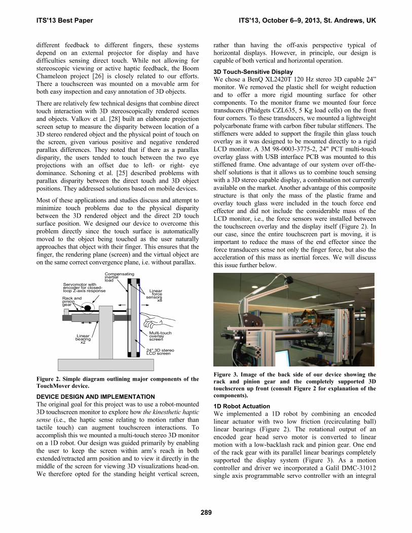
Figure 2. Simple diagram outlining major components of the
TouchMover device.
DEVICE DESIGN AND IMPLEMENTATION
The original goal for this project was to use a robot-mounted
3D touchscreen monitor to explore how the kinesthetic haptic
sense (i.e., the haptic sense relating to motion rather than
tactile touch) can augment touchscreen interactions. To
accomplish this we mounted a multi-touch stereo 3D monitor
on a 1D robot. Our design was guided primarily by enabling
the user to keep the screen within arm’s reach in both
extended/retracted arm position and to view it directly in the
middle of the screen for viewing 3D visualizations head-on.
We therefore opted for the standing height vertical screen,
rather than having the off-axis perspective typical of
horizontal displays. However, in principle, our design is
capable of both vertical and horizontal operation.
3D Touch-Sensitive Display
We chose a BenQ XL2420T 120 Hz stereo 3D capable 24”
monitor. We removed the plastic shell for weight reduction
and to offer a more rigid mounting surface for other
components. To the monitor frame we mounted four force
transducers (Phidgets CZL635, 5 Kg load cells) on the front
four corners. To these transducers, we mounted a lightweight
polycarbonate frame with carbon fiber tubular stiffeners. The
stiffeners were added to support the fragile thin glass touch
overlay as it was designed to be mounted directly to a rigid
LCD monitor. A 3M 98-0003-3775-2, 24" PCT multi-touch
overlay glass with USB interface PCB was mounted to this
stiffened frame. One advantage of our system over off-the-
shelf solutions is that it allows us to combine touch sensing
with a 3D stereo capable display, a combination not currently
available on the market. Another advantage of this composite
structure is that only the mass of the plastic frame and
overlay touch glass were included in the touch force end
effector and did not include the considerable mass of the
LCD monitor, i.e., the force sensors were installed between
the touchscreen overlay and the display itself (Figure 2). In
our case, since the entire touchscreen part is moving, it is
important to reduce the mass of the end effector since the
force transducers sense not only the finger force, but also the
acceleration of this mass as inertial forces. We will discuss
this issue further below.
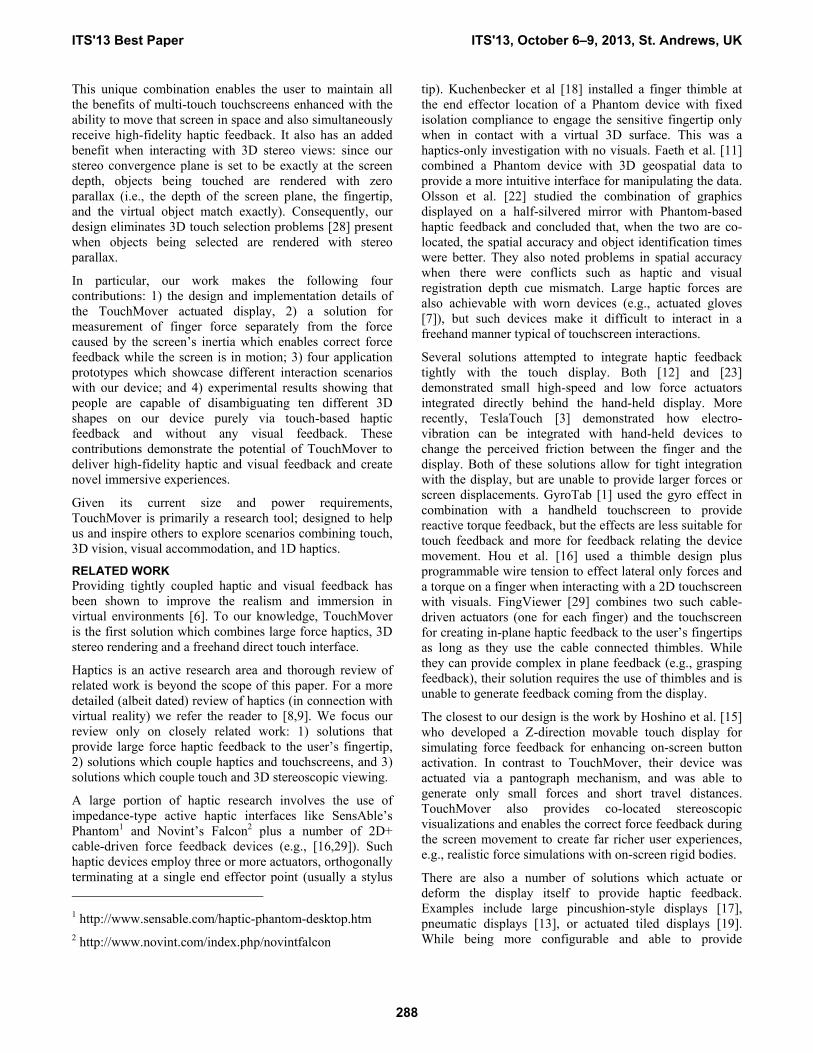
Figure 3. Image of the back side of our device showing the
rack and pinion gear and the completely supported 3D
touchscreen up front (consult Figure 2 for explanation of the
components).
1D Robot Actuation
We implemented a 1D robot by combining an encoded
linear actuator with two low friction (recirculating ball)
linear bearings (Figure 2). The rotational output of an
encoded gear head servo motor is converted to linear
motion with a low-backlash rack and pinion gear. One end
of the rack gear with its parallel linear bearings completely
supported the display system (Figure 3). As a motion
controller and driver we incorporated a Galil DMC-31012
single axis programmable servo controller with an integral
24" 3D stereo LCD screen
Servomotor with encoder for closed-loop Z-axis response
Linear bearing
x2
Linear force
sensorsx8
Compensating inertial load
Multi-touch overlay screen
Rack and pinion gear
ITS'13 Best Paper ITS'13, October 6–9, 2013, St. Andrews, UK
289

high speed 32-bit processor, 16-bit ADC and 800 watt
motor amplifier. The controller is capable of being
programmed in a high-level interpretive language
specifically for servo control.
The controller-amplifier communicated with a PC through a
high speed Ethernet connection using communication
interface provided by Galil3. The servo loop operated at 2
KHz within the controller and included processing the
motor’s encoder input, calculations for the system’s
position, integral and differential components (PID), servo
motor updates, processing external forces sensed,
communicating with the PC and processing for the
numerous modes of operation. The full system schematic is
depicted in Figure 4.
Most of the physical structure for the project was
implemented using 80-204 modular framing. As the robot
moved the display in a horizontally confined direction with
the display being oriented vertically, the whole device was
elevated such that the screen was situated at standard eye
level for ease of interaction (screen center at 160 cm from
the floor, our average user eye height). The small box
suspended above the screen is the IRLED transmitter used
to synchronize the stereo glasses (visible in Figure 1). The
operable depth that our screen can traverse is 36cm.
PCGP
U1
6 b
it
AD
C
4 4
3D
Mo
nito
r
Motion
controller
Eth
ern
et
Motor Encoder
AMP
Tou
chsc
reen
Co
mp
ensa
tio
n M
ass
Figure 4. TouchMover system schematic.
For the computer, we employed a quad-core PC running
Windows 8 with a GeForce GTX 660 Ti graphics card
which gave us the ability to render video graphics in stereo
using Nvidia’s 3D Vision5 output with their shutter glasses
for stereoscopic 3D. The computer communicates with the
motion controller via high speed Ethernet.
System Performance
To help the reader understand the capabilities of our device
we now present the frequency (speed) and force response
3 http://www.galilmc.com/
4 http://www.8020.net/
5 http://www.nvidia.com/object/3d-vision-main.html
analysis of TouchMover. Figure 5 shows a Bode plot
(frequency response) of our robotic system. We presented a
linear frequency sweep as the input to the motion controller
and recorded the screen’s physical response. At low
frequencies, the screen responds accurately to the
commanded input of +/- 5 cm. At higher frequencies, the
system cannot keep up and the amplitude drops below the
commanded +/- 5cm. The half-amplitude drop off is around
8 Hz which is fairly fast for a system this large. Figure 6
shows TouchMover’s force response. This shows that the
screen’s forcing ability fairly accurately corresponds to the
commanded forces. We chose the force and displacement
magnitudes that would be capable of simulating real-world
examples such as moving items with varying coefficients of
friction.
Figure 5. Bode plot of movement amplitude vs. frequency.
Figure 6. Plot of measured force vs. commanded force.
Simulating Haptic Sensations
When powered up, the controller causes the screen to
extend all the way to find the Z=0 home switch and zero the
encoder value when it finds it. The screen at this default
position is fully extended toward the user. When the user
touches the screen, they can push it into a desired Z position
with a light pressure of their fingertip. This is the default
behavior of our device which we refer to as the idle mode.
Since touchscreen interactions require the user’s finger to
remain in contact with the surface, the main challenge of
the idle mode is to ensure that the screen remains in contact
with the fingertip during interaction regardless of the
direction that the fingertip is moving in (i.e., both away and
ITS'13 Best Paper ITS'13, October 6–9, 2013, St. Andrews, UK
290
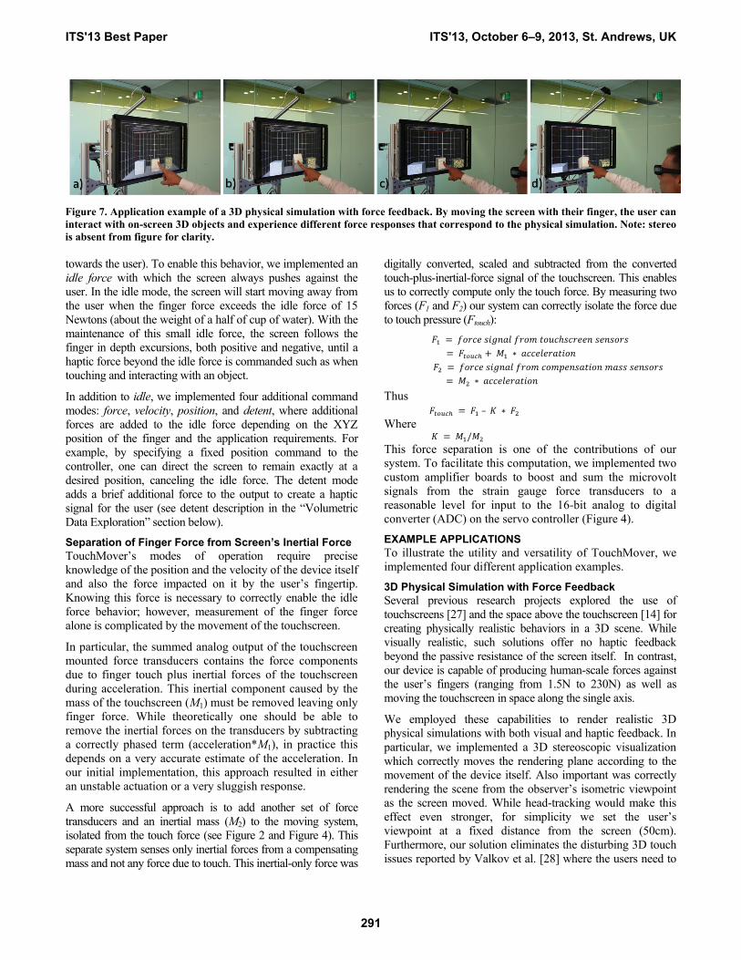
Figure 7. Application example of a 3D physical simulation with force feedback. By moving the screen with their finger, the user can
interact with on-screen 3D objects and experience different force responses that correspond to the physical simulation. Note: stereo
is absent from figure for clarity.
towards the user). To enable this behavior, we implemented an
idle force with which the screen always pushes against the
user. In the idle mode, the screen will start moving away from
the user when the finger force exceeds the idle force of 15
Newtons (about the weight of a half of cup of water). With the
maintenance of this small idle force, the screen follows the
finger in depth excursions, both positive and negative, until a
haptic force beyond the idle force is commanded such as when
touching and interacting with an object.
In addition to idle, we implemented four additional command
modes: force, velocity, position, and detent, where additional
forces are added to the idle force depending on the XYZ
position of the finger and the application requirements. For
example, by specifying a fixed position command to the
controller, one can direct the screen to remain exactly at a
desired position, canceling the idle force. The detent mode
adds a brief additional force to the output to create a haptic
signal for the user (see detent description in the “Volumetric
Data Exploration” section below).
Separation of Finger Force from Screen’s Inertial Force
TouchMover’s modes of operation require precise
knowledge of the position and the velocity of the device itself
and also the force impacted on it by the user’s fingertip.
Knowing this force is necessary to correctly enable the idle
force behavior; however, measurement of the finger force
alone is complicated by the movement of the touchscreen.
In particular, the summed analog output of the touchscreen
mounted force transducers contains the force components
due to finger touch plus inertial forces of the touchscreen
during acceleration. This inertial component caused by the
mass of the touchscreen (M1) must be removed leaving only
finger force. While theoretically one should be able to
remove the inertial forces on the transducers by subtracting
a correctly phased term (acceleration*M1), in practice this
depends on a very accurate estimate of the acceleration. In
our initial implementation, this approach resulted in either
an unstable actuation or a very sluggish response.
A more successful approach is to add another set of force
transducers and an inertial mass (M2) to the moving system,
isolated from the touch force (see Figure 2 and Figure 4). This
separate system senses only inertial forces from a compensating
mass and not any force due to touch. This inertial-only force was
digitally converted, scaled and subtracted from the converted
touch-plus-inertial-force signal of the touchscreen. This enables
us to correctly compute only the touch force. By measuring two
forces (F1 and F2) our system can correctly isolate the force due
to touch pressure (Ftouch):
Thus
–
Where
This force separation is one of the contributions of our
system. To facilitate this computation, we implemented two
custom amplifier boards to boost and sum the microvolt
signals from the strain gauge force transducers to a
reasonable level for input to the 16-bit analog to digital
converter (ADC) on the servo controller (Figure 4).
EXAMPLE APPLICATIONS
To illustrate the utility and versatility of TouchMover, we
implemented four different application examples.
3D Physical Simulation with Force Feedback
Several previous research projects explored the use of
touchscreens [27] and the space above the touchscreen [14] for
creating physically realistic behaviors in a 3D scene. While
visually realistic, such solutions offer no haptic feedback
beyond the passive resistance of the screen itself. In contrast,
our device is capable of producing human-scale forces against
the user’s fingers (ranging from 1.5N to 230N) as well as
moving the touchscreen in space along the single axis.
We employed these capabilities to render realistic 3D
physical simulations with both visual and haptic feedback. In
particular, we implemented a 3D stereoscopic visualization
which correctly moves the rendering plane according to the
movement of the device itself. Also important was correctly
rendering the scene from the observer’s isometric viewpoint
as the screen moved. While head-tracking would make this
effect even stronger, for simplicity we set the user’s
viewpoint at a fixed distance from the screen (50cm).
Furthermore, our solution eliminates the disturbing 3D touch
issues reported by Valkov et al. [28] where the users need to
ITS'13 Best Paper ITS'13, October 6–9, 2013, St. Andrews, UK
291

compensate for object parallax when touching stereoscopic
objects on a fixed screen. When using TouchMover, the
person’s fingertip, the depth of the rendering plane, and the
3D virtual object that the user is “touching” all match
correctly in depth.
In our application, the user is presented with three virtual
3D boxes, each with different virtual weights and respective
friction forces, and the device simulates the appropriate
force feedback when the user tries to push each box.
Placing the user’s finger on the screen allows the user to
gently push the screen in space until they encounter an
obstacle (e.g., a box). To simulate physical behaviors we
used Nvidia PhysX6 physics engine and we represent the tip
of the user’s finger with an invisible sphere proxy particle
(similar to the solutions in [14,27]). By applying a
simulated force on the proxy particle corresponding to the
actual force of the user’s finger on the touchscreen display,
we can correctly simulate the physical response that the
virtual object should exhibit and also update the device’s
force response to the user accordingly.
While able to generate realistic responses, this application
suffers from a fundamental limitation that only a single
touch point can be handled in most cases. This is because
the user interacts through one firm plane (the touchscreen)
and therefore we are unable to exert different forces onto
different touch contacts or sense different pressures from
different fingers. In practice, this limits us to effectively
using a single finger to interact with a 3D scene.
3D Contour Tracing
In addition to providing force feedback to the user, we can
simulate a rigid 3D surface at different depths by physically
moving the screen to the desired depth and locking it in
place. By updating the depth of the screen according to the
user’s XY touch input on the screen we can simulate the
surface contour of the 3D object as long as the object is
contained within the working volume of the device. In
contrast to the force feedback behavior, this mode of
operation can be thought of as forcing the screen to a
prescribed position.
To demonstrate this ability, we implemented a prototype
application in which the system haptically renders the 3D
6 http://www.nvidia.com/physx
contour of the touched object by moving the screen to the
correct depth according to the user’s finger XY position.
Figure 8 illustrates the user exploring the cup and the beach
ball 3D objects. As with the force feedback example above,
the user is restricted to a single finger.
Figure 8. 3D contour tracing application where the user feels
the shape of the 3D object by tracing their finger along its
surface. Note: stereo rendering is disabled for clarity.
Volumetric Data Exploration
In contrast to the above applications which deal with 3D
scenes, we now showcase using display movement and
haptics to enhance interactions with 2D data. We
implemented a volumetric medical image browser which
shows the MRI scanned data of a human brain. By gently
pushing on the screen the user can sweep the volume and
view different image slices of the brain (Figure 9).
When the user is interested in further exploring a particular
slice, they can touch an on-screen button with their non-
pointing finger along the left or right side of the screen, and
lock the screen position in place. This makes use of the
multi-touch capability of the 2D touch screen. Now they
can use their fingertip to annotate the slice while locking
the screen into position with the other finger. To facilitate
easier search and retrieval of such annotated slices, our
device implements a haptic detent to mark that slice
(inspired by Berdahl et al. [5]). In particular, whenever the
user is navigating and returns to that slice, the screen
braking force increases, causing it to stop at that slice. To
continue navigating, the user must exert a finger touch force
slightly higher than the idle force in order to move the
Figure 9. Interacting with medical volumetric data. We used the MRI scans of the human brain in our application. Pushing the
display back reveals different images of the scan dataset (a-b). The user can prevent the device from moving by touching on a stop
button (c) and then annotating the current slice with their finger (d).
ITS'13 Best Paper ITS'13, October 6–9, 2013, St. Andrews, UK
292
screen past this slice and turn the braking force off. This
detent makes it easier to find such information without
resorting to an on-screen visual solution.
Figure 10. An example of touchscreen interactions augmented
with kinematic haptics. Z-buttons (e.g., Yes confirming
deletion) require higher force and larger displacement of the
screen than others to eliminate accidental activation. The
button rendering serves as a progress bar, visually reinforcing
the amount of movement necessary to complete the action.
Haptic Button Activations
Lastly, we implemented a simple application which
demonstrates using TouchMover’s capabilities to reduce
accidental activation of touchscreen buttons (similar to
[15]). Users can be frustrated by accidental activations [4]
and inadvertent activations can be costly (e.g., accidental
confirmation to delete an item, illustrated in Figure 10). To
reduce such errors, we prototyped z-buttons (inspired by
Ramos et al. [24]) that activate based on screen movement
rather than touch or force only. In particular, to activate
such buttons the user must press the button and physically
move the screen by a certain amount. To make z-buttons
harder to activate accidentally, the system can apply more
resistance, thus ensuring that the user’s intentions are
certain. While simplistic, this example showcases how even
the simplest graphical user interface elements can benefit
from the extra input dimension offered by our device.
EXPERIMENT
We designed our visual+haptic display to augment the on-
screen multi-touch experience with co-located haptic
sensations, albeit in 1D. In contrast to many existing
touchscreen haptic solutions which exert minimal forces
and are used mostly to render different surface textures or
contact friction [3], our device is capable of exerting large
human-scale force as well as rendering significant
displacement in one dimension. This ability holds the
potential to effectively render the actual 3D shape of the
object that the user is touching on the screen. However, the
effectiveness of this 1D haptic information channel is
unclear, given that the user experiences it through the flat
surface of the display which does not necessarily reflect the
object’s surface normal at the point of touch.
To evaluate the fidelity and effectiveness of our system in
conveying the shape information through a 1D haptic
channel, we designed an experiment where participants
were asked to identify 3D shapes by touching them on the
screen without any visual feedback. This task is similar to
the haptic identification tasks suggested by Ballesteros and
Heller [2]. While the stated goal of our overall system is to
tightly integrate haptics with 3D rendering, evaluating the
combined experience would be dominated by visual
information. Therefore we focused our first experiment on
validating the expressiveness of haptics alone.
The primary goal of our experiment is to demonstrate the
expressive power of our device to render 3D geometry
using a 1D haptic channel. If we can show that our device
can convey the shape-defining characteristics to the user
using only 1D haptics, then combining such haptics with
co-located on-screen visuals should yield an even more
convincing experience.
Setup and Procedure
We recruited 12 participants (6 male, 6 female, mean age
37.5, std. dev. 10.2) from the community. Participants
received $5 compensation and the experiment took
approximately 30 minutes to complete.
The participants were asked to first familiarize themselves
with the capabilities of our device by practicing with the 3D
force feedback demos (Figure 7) and the 3D contour tracing
demo (Figure 8). They were asked to wear stereo shutter
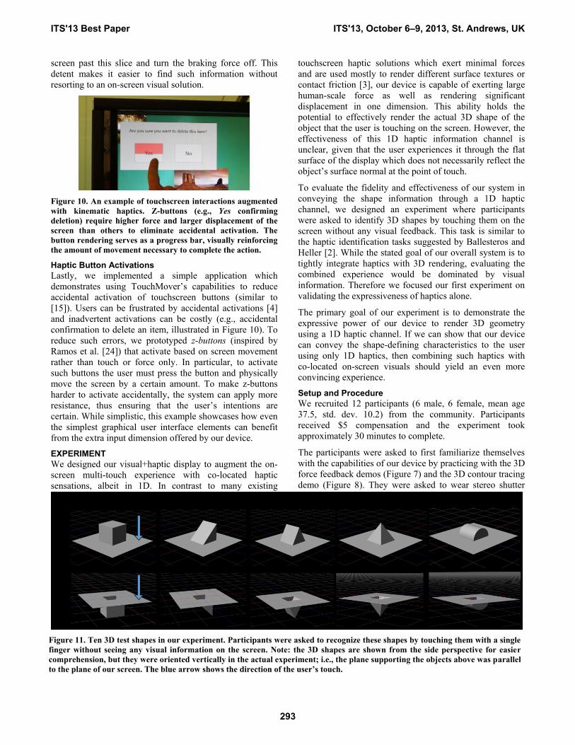
Figure 11. Ten 3D test shapes in our experiment. Participants were asked to recognize these shapes by touching them with a single
finger without seeing any visual information on the screen. Note: the 3D shapes are shown from the side perspective for easier
comprehension, but they were oriented vertically in the actual experiment; i.e., the plane supporting the objects above was parallel
to the plane of our screen. The blue arrow shows the direction of the user’s touch.
ITS'13 Best Paper ITS'13, October 6–9, 2013, St. Andrews, UK
293
glasses, stand in front of the device, and use only the index
finger of their dominant hand for all interaction with the
device during the experiment.
To test participants’ shape recognition performance, we
created a set of five 3D geometries: cube, side wedge,
wedge, pyramid, and half cylinder (Figure 11). All test
shapes share the same footprint (15cm square), but differ in
the overall 3D shape. Each shape was tested in both the
convex (protruding) and concave (recessed) orientation,
yielding 10 different 3D objects. We specifically chose
shapes with the same footprint so that the user could not
determine the shape of the object simply by the presence or
absence of haptic feedback in the 2D plane of the screen.
Our test shapes were centered on the screen in the middle of
the working volume of our device and haptically rendered
by our system. The shapes were rendered in vertical
orientation, either directly protruding towards the user
(convex) or recessed away from them (concave). For
example, the top of the pyramid was either the closest point
towards the user (convex) or the furthest point away from
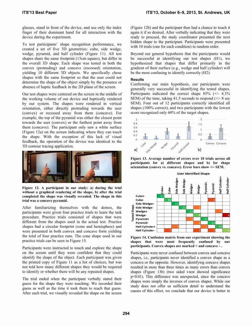
them (concave). The participant only saw a white surface
(Figure 12a) on the screen indicating where they can touch
the shape. With the exception of this lack of visual
feedback, the operation of the device was identical to the
3D contour tracing application.
Figure 12. A participant in our study: a) during the trial
without a graphical rendering of the shape, b) after the trial
completed the shape was visually revealed. The shape in this
trial was a concave pyramid.
After familiarizing themselves with the demos, the
participants were given four practice trials to learn the task
procedure. Practice trials consisted of shapes that were
different from the shapes used in the actual test. Practice
shapes had a circular footprint (cone and hemisphere) and
were presented in both convex and concave form yielding
the total of four practice runs. The cone shape used in our
practice trials can be seen in Figure 15.
Participants were instructed to touch and explore the shape
on the screen until they were confident that they could
identify the shape of the object. Each participant was given
the printed copy of Figure 11 as a list of choices, but was
not told how many different shapes they would be required
to identify or whether there will be any repeated shapes.
The trial ended when the participant verbally stated their
guess for the shape they were touching. We recorded their
guess as well as the time it took them to reach that guess.
After each trial, we visually revealed the shape on the screen
(Figure 12b) and the participant then had a chance to touch it
again it if so desired. After verbally indicating that they were
ready to proceed, the study coordinator presented the next
hidden shape to the participant. Participants were presented
with 10 trials (one for each condition) in random order.
Beyond our general hypothesis that the participants would
be successful at identifying our test shapes (H1), we
hypothesized that shapes that differ primarily in the
gradient of their surface (e.g., wedge and half cylinder) will
be the most confusing to identify correctly (H2).
Results
Confirming our main hypothesis, our participants were
generally very successful in identifying the tested shapes.
Participants indicated the correct shape 85% (+/- 4.3%
SEM) of the time, taking 41.5 seconds to respond (+/- 8 sec
SEM). Four out of 12 participants correctly identified all
shapes (100% correct), and two participants with the lowest
score recognized only 60% of the target shapes.
Figure 13. Average number of errors over 10 trials across all
participants for a) different shapes and b) for shape
orientation (convex vs. concave). Error bars show +/- SEM.
Figure 14. Confusion matrix from our experiment showing the
shapes that were most frequently confused by our
participants. Convex shapes are marked + and concave - .
Participants were never confused between convex and concave
shapes, i.e., participants never identified a convex shape as a
concave or the opposite. However, identifying concave shapes
resulted in more than three times as many errors than convex
shapes (Figure 13b) (two sided t-test showed significance
p<0.01). This difference was unexpected, since the concave
shapes were simply the inverses of convex shapes. While our
study does not offer us sufficient detail to understand the
causes of this effect, we conclude that our device is better in
ITS'13 Best Paper ITS'13, October 6–9, 2013, St. Andrews, UK
294
haptically rendering convex objects than concave ones. We
speculate that this might be due to the relative distance
between the object and the user (convex objects reduced this
distance) or that the user’s finger is better in interpreting
convex shapes when such are approximated with flat surfaces
like our screen. However, at this point, the full understanding
of this effect remains future work.
The half cylinder and the wedge were the most frequently
misclassified shapes (Figure 13a), confirming our second
hypothesis. Furthermore, the confusion matrix shown in
Figure 14 clearly reveals that the concave wedge was
misidentified as the concave half cylinder, while the
concave half cylinder was confused for concave cube,
wedge and pyramid. When asked about their difficulty in
recognizing these shapes, participants frequently
commented that it was difficult to differentiate the subtle
difference in haptically rendered curvature of the half
cylinder and the straight slope of the wedge.
We observed a significant learning effect between our
practice trials (68% recognition rate) and the test trials (85%
recognition rate), indicating that the participants got better
with practice. We also observed a learning effect within our
trials. When comparing the errors committed in the first five
trials to the errors committed in the second (last) five trials
we found a significant statistical difference for each
participant: in the first half the average number of errors =
1.08, while in the second half the average number of errors =
0.45 (statistical significance confirmed by p<0.05 with two
sided t-test). While this suggests that our participants would
probably improve even further with more practice, we are
encouraged that our participants achieved high recognition
rates even with very few practice trials.
Overall, the study results confirm that TouchMover is capable
of conveying significant amount of 3D shape information by
the 1D haptic channel alone. Furthermore, in a post-session
question and answer session with the participants, they all
expressed confidence that they could use the haptic channel
alone to identify simple shapes on our device.
DISCUSSION AND FUTURE WORK
In addition to our user experiment, we have demonstrated
TouchMover to hundreds of people at a public
demonstration event. While we gathered subjective
feedback only, our demo users were impressed with the
resolution, speed and capabilities of our device. We now
summarize the feedback from our experiences in interacting
with the device.
A problem we encountered early on was the friction
between the user’s fingertip and the touchscreen which
made moving along the screen while maintaining contact
difficult. We partially mitigated this effect by applying a
clear lubricant to the touchscreen, significantly lowering the
friction at the finger. Instead of this effective, but messy
solution, we are considering reducing the surface friction in
an electrostatic way (e.g., as suggested by [3]).
Though TouchMover is capable of rapid high-force and
large deflections, the interacting fingertip is always
touching a hard vertical plane of the screen. This makes
discovering features such as sharp edges and textures
difficult. For example, if the fingertip rests exactly on a
sharp edge, the device might produce a large displacement
with a minimal XY movement of the fingertip. This can be
highly disturbing with large discontinuities in depth since
the entire screen must move a large amount in a very short
time. We currently prevent our device from exerting forces
that could cause injuries.
Due to the rigid nature of our touchscreen, the force
feedback is felt equally on all fingers in contact with the
screen, which makes it impossible to provide the individual
haptic feedback to multiple fingers simultaneously. While
we focused our investigations on primarily single finger
interactions, multi-touch interactions are plausible and
implemented in our system (see “Volumetric Data
Exploration”), but the haptic feedback is not completely
correct in those instances.
While our preliminary experiment offered evidence of the
effectiveness of the 1D haptic channel to convey shape
information, more evaluations remain to be done. It is likely
that more realistic tasks (e.g., with distracter objects) would
make it more difficult to identify shapes. In addition, it also
remains future work to evaluate the effectiveness of
combined visuo-haptic experience, rather than haptics alone.
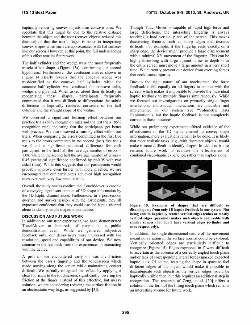
Figure 15. Examples of shapes that are difficult to
disambiguate from only 1D haptic feedback in our system. Not
being able to haptically render vertical edges (cube) or mostly
vertical edges (pyramid) makes such objects confusable with
similar shapes that don’t have vertical edges (cylinder and
cone respectively).
In addition, the single dimensional nature of the movement
meant no variation in the surface normal could be explored.
Vertically oriented edges are particularly difficult to
recognize (Figure 15). Edges expressed in Z were difficult
to ascertain as the absence of a correctly angled touch plane
and/or lack of corresponding lateral forces masked expected
haptic cues. Of course, rotating the shape in space to feel
different edges of the object would make it possible to
disambiguate such objects as the vertical edges would be
haptically visible then, but this requires an additional step in
recognition. The research of Zeng, et al. [30] offers a
solution in the form of the tilting touch plane which remains
an interesting avenue for future work.
ITS'13 Best Paper ITS'13, October 6–9, 2013, St. Andrews, UK
295
Similar to prior research which combined haptic response
and visual feedback [20] we observed that the latency and
response from the PC was often not fast enough (120 Hz) to
keep up with the controller for some of the modes of
motion required. To combat that, we let the PC specify
updates at the highest frequency available, but the
controller handles the direct output of the device given PC
instructions as a guideline. E.g., the controller can smooth
out the output between two PC updates. Achieving higher
PC throughput is an interesting area of future work.
Finally, there are a number of additional haptic stimuli we
plan to explore, such as changing the compliance normal to
an object’s surface to simulate soft objects, and simulating
various surface textures. The addition of small acoustic
actuators to the suspended touchscreen could help increase
the apparent frequency response of the system. While these
will not result in large, high speed screen movements, they
can add high frequencies to our high force, large deflection
kinesthetic movements, thus imparting sensations such as
texture and button clicks.
CONCLUSIONS
In this paper, we presented TouchMover, a novel
visual+haptic device which combines 3D stereo
visualizations, multi-touchscreen interactions, force sensing
and 1D haptic actuation for a unique immersive experience.
Our preliminary user study confirms that our device is
capable of conveying enough information through the haptic
channel alone for the user to be able to identify 10 different
3D shapes. Our example applications showcase how this
functionality can be employed to greatly improve the existing
touchscreen interactions with both 3D and 2D data.
While we understand that the size and complexity
requirements of this system make it impractical for wide-
spread use today, we believe that this device will serve as a
research platform for better understanding of the value of
the haptic sensations in touchscreen use.
REFERENCES 1. Badshah, A, Gupta, S., Morris, D., Patel, S.N., and Tan, D. (2012).
GyroTab: A Handheld Device that Provides Reactive Trorque
Feedback. In Proc. ACM CHI ’12. 3153-3156.
2. Ballesteros, S. and Heller, M. (2008). Haptic object identification. In
Human Haptic Perception, Basics and Applications. Grunwald, M.
ed., 207-222.
3. Bau, O., Poupyrev, I., Israr, A, Harrison, C. (2010). TeslaTouch:
Electrovibration for Touch Surfaces. In Proc. ACM UIST’10. 283-292.
4. Benko, H. and Wigdor, D. (2010). Imprecision, Inaccuracy, and
Frustration: The Tale of Touch Input. In Tabletops - Horizontal
Interactive Displays. Christian Mueller-Tomfelde (ed.) Springer-
Verlag London Ltd., April 2010.
5. Berdahl, E., Smith, J., Weinzierl, S., Niemeyer, G. (2013). Force-
Sensitive Detents Improve User Performance for Linear Selection
Tasks. IEEE Transactions on Haptics, 2013.
6. Biggs, S.J. and Srinivasan, M.A. (2002). Haptic Interfaces. Handbook
of Virtual Environments. K. Stanney (ed.), Lawrence Erlbaum
Associates. 93-115.
7. Bouzid, M., Burdea, G., Popescu, G., and Boian, R. (2002). The
Rutgers Master II—New Design Force-Feedback Glove. IEEE/ASME
Transactions on Mechatronics. Vol. 7. No.2.
8. Bowman, D., Kruijff, E., LaViola, J.J., and Poupyrev, I. (2004). 3D
User Interfaces: Theory and Practice. Addison-Wesley, Boston, Ma.
9. Burdea, G.C. (1996). Force and touch feedback for virtual reality,
John Wiley & Sons, Inc., New York, NY.
10. Cha, J., Eid, M., Saddik, A. (2009). Touchable 3D Video System.
ACM Transactions on Multimedia Computing, Communications and
Applications.
11. Faeth, A., Oren, M., Harding, C. (2008). Combining 3-D
geovisualization with force feedback driven user interaction. In
Workshop on Advances in Geographic Information Systems ’08.
12. Fukumoto, M. and Sugimura, T. 2001. Active click: tactile feedback
for touch panels. In ACM CHI '01 Extended Abstracts. 121-122.
13. Harrison, C. and Hudson, S. E. (2009). Providing Dynamically
Changeable Physical Buttons on a Visual Display. In Proc. ACM CHI
'09. 299-308.
14. Hilliges, O., Izadi, S., Wilson, A., Hodges, S., Garcia-Mendoza, A.,
and Butz, A. (2009). Interactions in the Air: Adding Further Depth to
Interactive Tabletops. In Proc. ACM UIST ‘09.
15. Hoshino, T., Minemoto, T., and Tsukada, Y. (2007) Display Unit with
Touch Panel. US Patent No. 7312791. Filed Aug. 27, 2003. Issued
Dec. 25, 2007.
16. Hou, Z., Zhang, Y., Yanf, Y. (2012). Enhancing Touch Screen Games
Through a Cable-driven Force Feedback Device. In Proc. Inter.
Conference on Virtual Reality and Visualization.
17. Iwata, H., Yano, H., Nakaizumi, F., and Kawamura, R. (2001). Project
FEELEX: adding haptic surface to graphics. In Proc. ACM
SIGGRAPH '01. 469-476.
18. Kuchenbecker, K., Ferguson, D., Kutzer, M., Moses, M., Okamura, A.
(2008). The Touch Thimble: Providing Fingertip Contact Feedback
During Point-Force Haptic Interaction. In Proc. Symposium on Haptic
Interfaces for Virtual Environment and Teleoperator Systems.
19. Leithinger, D., Lakatos, D., DeVincenzi, A., Blackshaw, M. and Ishii,
H. (2011). Direct and gestural interaction with relief: a 2.5D shape
display. In Proc. ACM UIST '11. 541-548.
20. Mark, W. R., Randolph, S. D., Finch, M., Van Verth, J.M., and
Taylor, R.M. (1996). Adding force feedback to graphics systems:
issues and solutions. In Proc. ACM SIGGRAPH '96. 447-452.
21. Massie,T., and Salisbury, K. (1994). The PHANToM Haptic Interface:
A Device for Probing Virtual Objects. In ASME Haptic Interfaces for
Virtual Environment and Teleoperator Systems, DSC-Vol.55-1.
22. Olsson, P., Nysjo, F., Seipel, S., Carlbom, I. (2012). Physically co-
located haptic interaction with 3D displays. In Proc. Symposium on
Haptic Interfaces for Virtual Environment and Teleoperator Systems
‘12.
23. Poupyrev, I. and Maruyama, S. (2003). Tactile interfaces for small
touch screens. In Proc. ACM UIST ‘03. 217-220.
24. Ramos, G., Boulos, M., Balakrishnan, R. (2004). Pressure Widgets. In
Proc. ACM CHI ‘04. 487-494.
25. Schöning, J., Steinicke, F., Valkov, D., Krüger, A. and Hinrichs, K. H.
(2009). Bimanual interaction with interscopic multi-touch surfaces. In
Proc. INTERACT ’09. 40–53.
26. Tsang, M., Fitzmaurice, G., Kurtenbach, G. Khan, A., Buxton, B.
(2002). Boom Chameleon: Simultaneous capture of 3D viewpoint,
voice and gesture annotations on a spatially-aware display. In Proc.
ACM UIST ‘02.
27. Wilson, A., Izadi, S., Hilliges, O., Garcia-Mendoza, A., and Kirk, D.
(2009). Bringing Physics to the Surface, In ACM UIST ‘09.
28. Valkov, D., Steinicke, F., Bruder, G., Hinrichs, K. (2011). 2D
Touching of 3D Stereoscopic Objects. In Proc. ACM CHI ‘11.
29. Yang, Y., Zhang, Y., Hou, Z., Chen, Z., Lemaire-Semail, B. (2011).
FingViewer: a New Multi-Touch Force Feedback Touch Screen. In
Proc. of IEEE International Conference on Consumer Electronics ‘11.
30. Zeng, T., Lemaire-Semail, B., Giraud, F., Messaoudi, A., Bouscayrol,
A. (2012). Position control of a 3 DOF platform for haptic shape
rendering. In Proc. of 15th International Power Electronics and
Motion Control Conference.
ITS'13 Best Paper ITS'13, October 6–9, 2013, St. Andrews, UK
296