
To,oth Root Stresses of Spiral Bevel Gears - Gear …oth Root Stresses of Spiral Bevel Gears Hans...
11
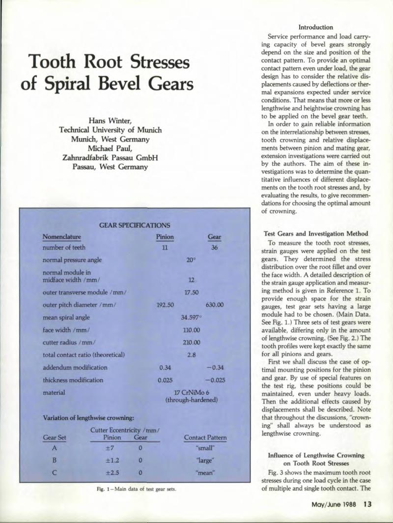
To,oth Root Stresses of Spiral Bevel Gears Hans Winter, T echnieal Umversity of Munidt Munich, West Germany Michael Paul, Zahnradfabrik Passau GmbH Passau, West Germany GEAR 5PEORCATION5 Nomenclature Pinion Gear number of teeth 11 36 normal pressure angle 20° normal module in midface width I mm I 12 outer transverse module Imml 17.50 outer pitch diameter I mm I 192.50 630.00 mean spiral angle 34.597° face width I mm I 110.00 cutter radius Imml 210.00 total contact ratio (theoretical) 2.8 addendum modification 0.34 -0.34 thickness modification 0.025 -0.025 material 17CrNiMo6 (through-hardened) Variation of lengthwise crowning: Cutter Eccentricity Imml Pinion Gear Gear Set A Contact Pattern Introduction Service performance and load carry- ing capacity of bevel gears stron-81y depend on the size and position of the contact pattern. To provide an optimal contact pattern even under load, the gear design has to consider the relative dis- placements caused by deflections or ther- ma1 expansions expected under service conditions, That means that more or less lengthwise and heightwise crowning has to be applied on the bevel gear teeth. In order to gain reliable information on the interrelationship between stresses, tooth crowning and relative displace- ments between pinion and mating gear, extension investigations were carried out by the authors. The aim of these in- vestigations was to determine the quan- titative influences of different displace- ments on the tooth root stresses and, by evaluating the results, to give recommen- dations for choosing the optimal. amount of crowning. ±7 0 "small" Test Gears and Investigation Method To measure the tooth root stresses, strain gauges were applied on the test gears. They determined the stress distribution over the root filletand over the Face width ..A detailed description of the strain gauge application and measur- ing method is given in Reference 1. To, provide enough space for the strain gauges, test gear sets having a large module had to be chosen. (Main Data. See Fig. 1.) Three sets of test gears were available, differing only inthe amount of lengthwise crowning. (See Fig. 2,) The tooth profiles were kept exactly thesame for an pinions and gears. First we shall discuss the case of op- timal mounting positions for the pinion and gear. By use of special features on the test rig, these positions could be maintained, even under heavy loads. Then the additional effects caused by displacements shall be described. Note that throughout the discussions, "crown- ing" shan always be understood as lengthwise crowning. Influence 'of Lengthwise Crowning on Tooth Root 'Str,esses Fig. 3 shows the maximum tooth root stresses during one load cyde in the case of multiple and single tooth contact. The Mcry/June 1988 13 B C "large" ±1.2 o ±2.S 0 "mean" ~ig. I-Main data.of test gear sets.
Transcript of To,oth Root Stresses of Spiral Bevel Gears - Gear …oth Root Stresses of Spiral Bevel Gears Hans...
To,oth Root Stressesof Spiral Bevel Gears
Hans Winter,Technieal Umversity of Munidt
Munich, West GermanyMichael Paul,
Zahnradfabrik Passau GmbHPassau, West Germany
GEAR 5PEORCATION5
Nomenclature Pinion Gearnumber of teeth 11 36
normal pressure angle 20°
normal module inmidface width Imm I 12
outer transverse module Imml 17.50
outer pitch diameter Imm I 192.50 630.00
mean spiral angle 34.597°
face width Imm I 110.00
cutter radius Imml 210.00
total contact ratio (theoretical) 2.8addendum modification 0.34 -0.34
thickness modification 0.025 -0.025
material 17CrNiMo6(through-hardened)
Variation of lengthwise crowning:
Cutter Eccentricity ImmlPinion GearGear Set
AContact Pattern
IntroductionService performance and load carry-
ing capacity of bevel gears stron-81ydepend on the size and position of thecontact pattern. To provide an optimalcontact pattern even under load, the geardesign has to consider the relative dis-placements caused by deflections or ther-ma1 expansions expected under serviceconditions, That means that more or lesslengthwise and heightwise crowning hasto be applied on the bevel gear teeth.
In order to gain reliable informationon the interrelationship between stresses,tooth crowning and relative displace-ments between pinion and mating gear,extension investigations were carried outby the authors. The aim of these in-vestigations was to determine the quan-titative influences of different displace-ments on the tooth root stresses and, byevaluating the results, to give recommen-dations for choosing the optimal. amountof crowning.
±7 0 "small"
Test Gears and Investigation MethodTo measure the tooth root stresses,
strain gauges were applied on the testgears. They determined the stressdistribution over the root filletand overthe Face width ..A detailed description ofthe strain gauge application and measur-ing method is given in Reference 1. To,provide enough space for the straingauges, test gear sets having a largemodule had to be chosen. (Main Data.See Fig. 1.) Three sets of test gears wereavailable, differing only inthe amountof lengthwise crowning. (See Fig. 2,) Thetooth profiles were kept exactly thesamefor an pinions and gears.
First we shall discuss the case of op-timal mounting positions for the pinionand gear. By use of special features onthe test rig, these positions could bemaintained, even under heavy loads.Then the additional effects caused bydisplacements shall be described. Notethat throughout the discussions, "crown-ing" shan always be understood aslengthwise crowning.
Influence 'of Lengthwise Crowningon Tooth Root 'Str,esses
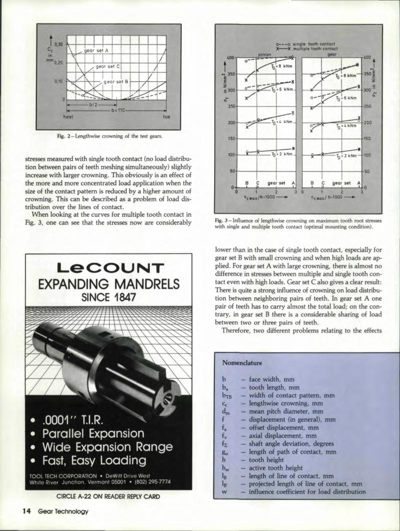
Fig. 3 shows the maximum tooth rootstresses during one load cyde in the caseof multiple and single tooth contact. The
Mcry/June 1988 13
B
C
"large"±1.2 o±2.S 0 "mean"
~ig. I-Main data.of test gear sets.
t 0,)0Ccin
mmO,20
I1,\ _ ~eor set A
'\ I /\ /, gear set C I~~
II V-:""<, '-. /1geYSj' B
"/ ......V,
~'"~~ 1/ ~ --~. ~b12------l
b = 110
0,10
o
heel toe
Fig. 2 - Lengthwise crowning of the test gears.
stresses measured with single tooth contact (no load distribu-tion between pairs of teeth meshing simultaneously) slightlyincrease with targer crowning" This obviously is an effect ofthe more and more concentrated load application when thesize of the contact pattern is reduced bya higher amount ofcrowning. This can be described as a problem of load dis-trlbutlonover the lines of contact.
When looking at the curves for multiple tooth contact inFig. 3, one can see that the stresses now are considerably
L,eCOUINTEXPAIND'iIN'G IMAN'DRELS
SINCE, 11847~~ ~-----~~-""".Jii#1'~.1'.#'~'." """''''''''''''''''''''~'''''- - -- - - i:!'Ioi:II!' ~JII""""..I'..tiJIII!'~~~ .. ~~_._. __ ~; _~"""",II"__• • __ ': ._.~" ...............,...11.... -----..,,, ...~ V ~I'- _-.............. .". . ~ ... ~
I..~'- -~ ..-- ~: ~"" ",.•~', " ,-• .0001" T.I.R. "-.' Parallel Expansion• Wide Expansion Range• Fast, Easy LoadingTOOL TECH CORPORATION • DeWitt Drlvp WestWhde River Junction, Vermont 05001 • 1802) 295~7774
CU~CLE A,.22 ON READER REPLY CARD
1'4 Gear feohnology
0---0 sln~le tooth cDntactx-x l1'Iulhple tooth cantad
.--_--.-......:.gea.;,.;...t -,---,.400
fJ50"'E
!zE
1--*--+-~:loo-"=-....=..:.tJOO0-b
.. I
250+'--+----+---1
150+----+--+----1
"-Jt~~~tr-;;~·100+ b= 2 kNm
SO+----+--~---~ r----+-----l-----+50I B C gear set Ao -- B C gear 511 A
o2 3
ceria.! ".tOOO-o 1 2 3 0
cella./b.fOOD--
Fig. 3 -lnfIuence of lengthwise crowning on maximum tooth root stresseswith single and multiple tooth contact (optimal mounting condition).
lower than in the case of single tooth contact, especially forgear set B with smaUcrowning and when high loads are ap-plied. For gear set A with large crowning, there is almost nodifference in stresses between multiple and single tooth con-tact even with high loads. Gear set C also gives a dear resultiThere is quite a strong influence of crowning on load distribu-tion between neighboring pairs of teeth. In gear set A onepair of teeth has to carry almost the total load; on the con-trary, in. gear set B there is a considerable sharing of loadbetween two or three pairs of teeth,
Therefore, two different problems relating to theeHects
Nomenclature
b - face width, mmba tooth length, mmb-rB width of contact pattern, mmCc lengthwise crowning, mmdm mean pitch diameter, mmf displacement (in general), mmfa offset displacement, mmfv axial displacement, mmfr; shaft angle deviation, degreesg". length of path of contact, mmh tooth heighthw active tooth heightIB length of line of contact, mmIS' projected length of line of contact, mmw influence coefficient for load distribution

gear set0--.0(] A0----0 Bb--t!J. C
Fig. 4 -lnflumoe of lengthwise ao1.'lI1IDgon the load distribution over the lines of contact (single tooth conract).
ofcrowrUng have to' be discussed: Load distribution over linesof contact and load distribution between gear pairs meshingsimultaneously. We Can Solve Your
I Distortionand WearProblems ..
Load O.istributi.on 'OY,er Lines ,of Contact.By using the superposition principle the load distribution
over the lines of contact could be determined from root stressmeasurements with pointwise load .application on the teeth.lFig.4 shows the results for the test gears valid for the desired
• State-of-the-art gearharde, nlngequipmentincluding 4 NATCOsubmerged processmachines and 3 AJAXgear scanninglmachines.
• Specialists in hard-ening helical andbevel gears andcontour hardening: ofgear teeth.
• We can toot to meetany production needs.
• Write for free capa-bilities brochure.American Metal T~eatlng'ComJ:!any1043 East 62nd StreetCleveland. Ohio 44103(216) 431-4492
mesh positionforce, Ntangential force in mean face width, N
- optimization factor for lengthwise crowning- lengthwise crowning factor- displacement factor- measure point- position of point load
outer cone distance, mminner cone distance, mmtorque (on pinion) carried by one pair of teeth,Nmtotal pinion torque, Nm
- load sharing factor- base spiral angle, degrees- inclination angle of line of contact, degree- stress in depthwise direction, N/mm2
EFIFml
K.:KF/3-cKF/3-fMP~RiTE
Specialists In Mining and Off- The-Road Squlpmem
'OIl~CUE.A-7 ON IREAIOERREPLV CAIRO
May/June, 1988 15
gear set A
gear set C
pitchcone
pitchcone
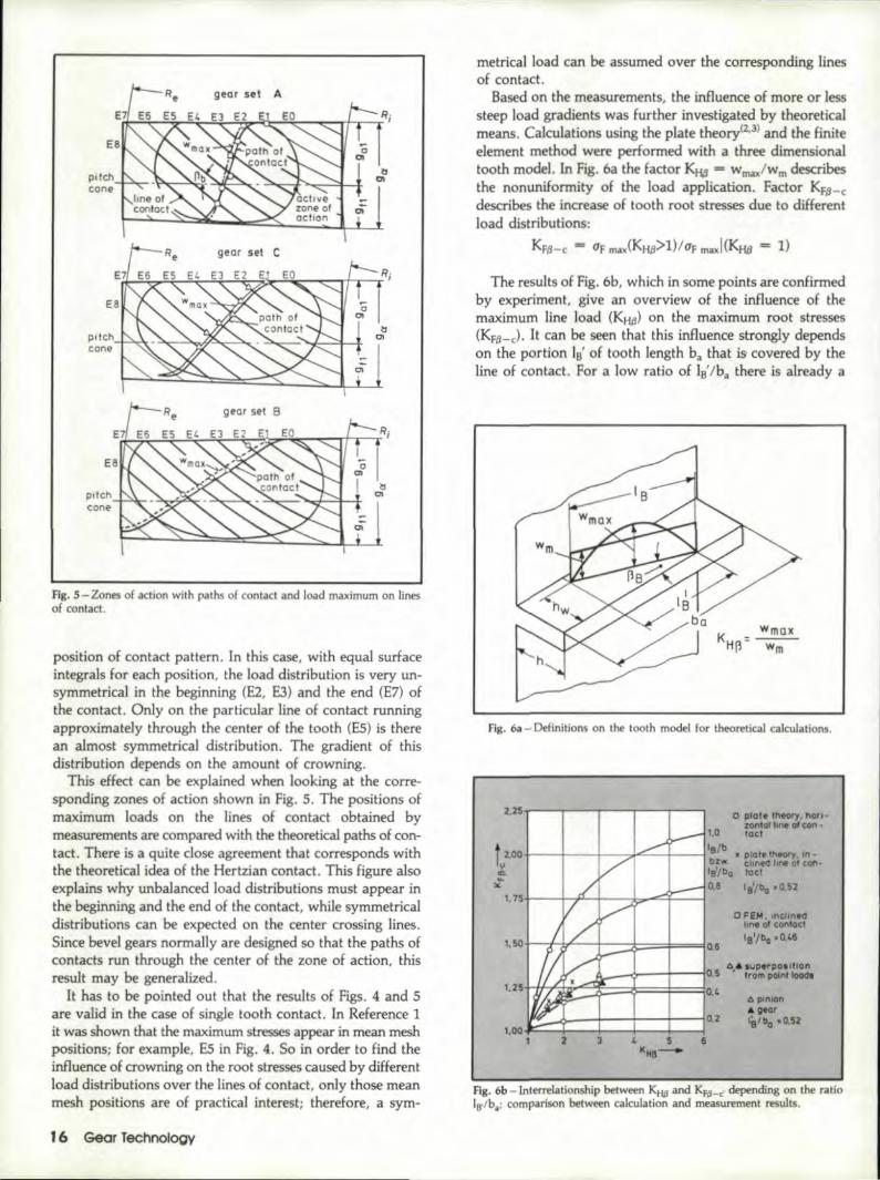
FIg. S-Zones of action wifh paths of contact and load maximum on linesof contact.
position of contact pattern. In this case, with equal surfaceintegrals for each position, the load distribution is very un-symmetrical in the beginning (E2, E3) and the end (E7) ofthe contact. Only on the particular line of contact runningapproximately through the center of the tooth (E5) is therean almost symmetrical distribution. The gradient of thisdistribution depends on the amount .of crowning.
This ,effect can be explained when looking at the corre-sponding zones of action shown in Fig. S. The positions ofmaximum loads on the lines of contact obtained bymeasurements are compared with the theoretical paths of con-tact. There is a quite dose agreement that corresponds withthe theoretical idea of the Hertzian contact, This figure alsoexplains why unbalanced load distributions must appear inthe beginning and t:he end of the contact, while symmetricaldistributions can be expected on the center erossinglines,Since bevel. gears normally are designed so that the paths ofcontacts run through thecenter of the zone of ad ion, thisresult may be generalized.
It has to be pointed out that the results of Figs. 4 and 5are valid in the case of single tooth contact. In Reference 1it was mown tha.t the maximum stresses appear in mean meshpositions; for example, E5 in .Fig..4. So in order to find theinfluence of crowning on the root stresses caused by differentloaddistnbutions over t.ne lines of contact, only those meanmesh positions are of practical interest; therefore, a sym-
16 Gear Technolog,y
metrical load can be assumed over the corresponding linesof contact.
Based on the measurements, the influence of more or lesssteep load gradients was further investigated by theoreticalmeans ..Calculations using the plate theory(2.3J and the finiteelement method were performed with a three dimensional.tooth model. In Fig. 6a the fa.d.QI KHtI = wmD/wm describesthe nonun:ifonnity of the load application. Factor ~6-cdescribes the increase of tooth root stresses due to d_ilff,erentload distribution~.
KFt/-c "'" Up .rrw:(KHtI>l)/up tl'lOIXI(KHg = 1)
The results of Fig ..6b, which in some points are confirmedby experiment, give an overview of the influence of themaximum line load (KH,/l) on the maximum root stresses(Kp~-c). It can be seen that this influence strongly dependson the portion lB' of tooth length ba that is covered by theline of contact. For a low ratio of IB'/ba there is already a
Fig. 6a - Definitions on the tooth model for theoretical calculations.
I
0 plate Ih<!Of)'.1\0fl-zonlol lone 01 con -
~ 1.0 lociI, /b
-I---t---t---:;;""""-+----j B • plolelhl'Ol)'. in «
bzw. cLm-ed line 0' con-'s/ba loci
I 0,8 ,BYba .0,52+---~~~--~~~--~C FE"', Incl,ned
lone 01 contact
lB'/bo .0,/,6
;0 pinionA gear
!:..-O_-j--+--+--jO.2 lalba .0.52
Fig. 6b -Int'enelationship between KIiI' and KF/I-c· depending on the ratioIs-lb.; ,comparison between calculation and measurement results.

strong stress c-oncentration below the short lin.e of contact'even with a unifonn load distribution. In this casea moreor less steep load gradient has only a minor effect.. On theother hand, a large ratio 10'/b, is quite sensitive to loaddistribution.
In the case of spiTaJ bevel gears, usually one will have a ratio,of lo/ha "'" 10.5 under design load. Assuming approx-imatelythis value, the factors (KH,8) and (KF~-c)can be plot-ted versus the amount of lengthwise crowning. (See fig. 7.)This figureal[ows a general estimation of this ·effect for prac-tical applications.
lnflluence of Crowning on. Load SharingWith MUltiple 'Iooth Contact
Fig. 3 already showed that the crowningeffeds con-siderably the maximum portion of load carried by one pairof teeth during one load cycle. Fig. 8 shows this effectmeasured with the test gear sets under two different loads.
2.00.,.---r---..----,
te1.75 -1----1----1-----1
:.:
Flrltl b In NImm_
o 227 454 680 907 1131.3.0"'1---+---1---1----1----1
21.0+---+---+----1---+-----1o 4 6 8 10
TG In kNm_
i1.0
....I.:J 0.8-........
Fls. 7 - Influence of lengthwise crownlng 01'1 Ktip andKF~' (KHP. see fig. 4; KKP-c' see Fig. 6b.)
0.6
Il !1)\"\I
I
'/"
I \ _
'/ .~I 1\ \ \r 1\:\I V/ I \ \~,~11/ 11,,/ \1\\
J.t /'I
i~
I .
!I l" .,i,
0.4
0.2
mesh position
Fis. 9 - Influence of load on the effective total contact ratio measured £'01the test gear sets,
looking at the low load (TG = 4: kNm), one cansee thatfor gear sets A and C (large and mean crowning) there is anarea of eHective single tooth contact, (One pair of teeth car-ries 100% load, T E/TG = 1.) for gear set B (small crown-ing) the maximum portion of load is about 95%.
\l\lhen higher torque ITG =8 kNm) is .applied only in gearset A,. one pair of teeth still has to carry the 'to'taJ load fora short time: i.e., with this torque on gear set. A just thesignificant value of E')'W = 2 for the effective total contactratio is reached. So from these results, the in't,errelationshipbetween load, crowning and effective contact ratio 'can bederived. (See Fig .. 9.)
It is of interest to compare the effective (,ontact ratio deter-mined by measurement with calculated contact ratios aecerd-ing to AGMA(4) or DIN(S) standards ..Fig. lOa. compares the
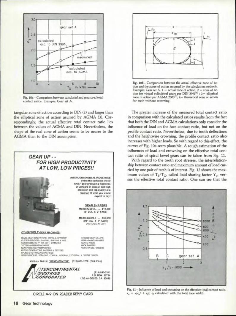
values for the example ofgear set A. The resultsshow that the con tadratios aceording to DIN3991 are too high over thewhole torque range; andthat the AGMA values fitquite well at low torques ..Until higher torques arereached, the measuredcontact ratio. increasesmore rapidly than thecalculated contact ratio ..
The differences can beexplained by ,consideringthe zones of action as-sumed by the calculationmethods. (See Fig. lOb.)The real. zone of action (1)determined by experimentis smaller than the rec-
mesh positioll --
Fig. 8 - InfIutcnc:eof crowning onportion of load carried. by one pair of teeth during one lead cyd .
oEO E1 E2 EJ E4 E5 E6 E7 E8EO El E2 EJ E4 E5 E6 E7
gear set0---0 A0---.0 BA-lJ. C
r---,---r-..-..=.......,.....~"E"'''"""'I'--r-"Tl.0
f~
1--11--r~fLI7'-;'-+--I--'llMr+---l 0.6
May IJUne 1988 l' l'
3.0..---------r1-""T""1-...,,----------,georse! A
f 2.5+---+--+----+---1---1cclculaled 1___
cec, 10 DIN 3,991\~, ___o ~ -.~
2.+-~-..-..-+~-~~~-,,-.9-'~-m-.~-.~~s~ur~e~d-l.c'.....•..'/ _--1'-1.5+---.,J.,.,..__.c:._~_ ....II..,,-_ ...."~,- ~--+----I
~I , eclcutoted;;,.-' ace. to AGMA
I I1.0+---.......r--+--+----+---io t. 6 B 10TG In kNm_
2
fig. lOa - Comparison between calculated and measured totalcontact ratios. Example: Cearset A.
tangular zone of actionaccording to DIN (2) and larger thanthe elliptical zone of action asumed by AGMA (3). Cor-respondingly, the actual effective total contact ratio liesbetween the values of AGMAand DIN. Nevertheless, theshape of the real zone ofaction seems to be nearer to theAGMA than to the DIN assumption.
GEAR UP ,~,~,FOR' HIGH PRODUCTIVITY
AT LO~ LO'W,PR1CES!!
INTERCONTENENTAl. INDUSTRIES,oilers the, complete line ot'
WOLF gear prDduclng: m.c'hine~IIIunheard 01'prlcesl Gel highprecision lllid lop qUlIll'Ylll
W1i2Jl ot' what you would,expect 10 pay I
GEAR SHA'PERSModel fGS8-2 ••.••. $1,9,450
(8," IDIA, )I 2" FACE I
Model tGS2Q.5 ••.• $55.950'(20" DIA. )I S" FACE)
(PfCTIJREDAT LEFT)
OTHER WOLF GEAR MACHINES:
BEVELGEARGENERATOAS: SPIRAL & STRAIGHTCUTTER GRINDERS, SHAPING. Sli<'.VING & l-IOIIGEA.R ~RS: " TO 40 FT DIAMETERTOOTH CAMFEFW3 MI\CHIIIESGEAR NOISE TES'I'N:l ~HYl'()jDGENERATORS, LAPI'EFIS & TESTERSSPUNE SHAFT IoIIUJNG MACHINESGEAR GRJIIDERS: stftl.lGHr. CGIICAL. INTEFINAl. CYClOOW. & 'WORM" WHEEl.
CYCLOID GEAR M1LLERS(lEAR fO,IN(l~
GEAASH<\VERSFIACI< SHAPERS~ Wl-£El. HOB8ERS
Visit OUf Detroit "OEMo.CENTER" (31'3)651-1200 (Dick Filla)
TERCONTINENTAL'lJ~Sr/iIES p.~.1~~~a33~~~~ORPORATED LOS A_NGElES, CA 90036
CIRCLE A-9 ON READER REPLYCAiRD
FIg. lOb-Comparison between the actual effective zone of ac-tion and the zones, ·01action assumed by the calculation methods.Example: Gear set A. 1 - actual zone of acl:ion;2 - zone 'of ac-tion for virtual cylindrical gears per DIN 3991(4) ; 3,- ellipticalzone of action per AGMA 2003(51;4- theoretical zone of actlon~o.rteeth without crowning.
The greater increase of the measured total contact ratioin comparison with the calculated ratios .results from the factthat both the DIN and A:GMA calculations only consider theinfluence of load on the face contact ratio, but not on theprofile contact ratio', Nevertheless, due to tooth. deflectionsand the heightwise crowning, the profile contact ratioalsoincreases with higher loads. So with regard to this effect, thecurves of Fig, lOa seem plausible. A rough estimation of theinfluences of load and crowning on the effective total con-tad ratio of spiral bevel gears can betaken from Fig. 1l.
With regard to the tooth root stresses, the interrelation-ship between contact ratio and maximum amount of load car-ried by one pair of teeth is of interest. Fig ..12 shows the max-imum values of T EfT G, called load sharing factor Y'I'"ver-sus the effediv·e total contact ratio .. One can see that the
1,2 I
t I, O+""~:r-~b:-~_~';;;::;:::~--<:loJ
tee
1000 -%800 ,~
600 .a-'00 EII.
200
)oiO
1.1--!a ,S +-----1'""':::----1-""""-==..-1w
1 2eel b . 1000
3
Fig..ll-lnflu neeof load and crowning on the effective total contact ratio,l" - ../Eal + EI. Efj calculated with the lotal face width.

r 1.0 i
"o!..0.9+---+~-'j~---1-----l~-- I~O.8+----+---I ""-I----l"
0.6o 2.0 2.25 2.50
El'ol-2.75
Fig. 12 - Load sharing factor Y~. Comparative values accord-ing 1.0 Coleman. (6)
measuring results conespondquite well 'to an earlier formula-tion of Coieman(6) if the effective values of contact ratio areused here as well. From this investigation, we may ,concludethat the influenci! ,of lengthwise crowning on the tooth rootstresses resulting froma differing load distribution over thelines of contact (factor KF,B-c), and from a differing loadsharing (factor Y'I') can be estimated quantitatively.
Influence of Relative DisplacementsThe results discussed before were valid for optimal posi-
tions of the contact patterns even under heavy loads; i.e.,an ideal stiff ,configw..a.tion was simulated on the test rig.Nevertheless, under practical conditions some displacementof pinion and gear cannot be avoided. Therefore, this in-vestigation also covers the influence 'of those relativedisplacements on the root stresses. By performing similarmeasurements on the threet:est gearsets, 'the ,effect of crown-ing could be considered too .. F~g..13 gives a definition of allrelative displacements that can. occur between pinion andgear,
To describe the difJierence in maximum root stresses when
Fig. lJ- Definition ofrelative displacements be-tween pinion and gear. (71
fa
+1--.
IINr nl(].-._.(] AO~---<l B
t.JI...-_-.-_t::Pi;;;"' ...on......__ llo-,- F4.;;C;...-.,-_!l~~Fr~-,-_--.rI. J
luI'" ,"; r-,";1.1 '-.e I -...... r~, I
:II: '~I-~1.0 Kt-:~-':::i.
0,9~--+---+---+----":::--~
O.II+---I---t---+--I ~-+--+--~-1Q'-1,52 -0.76 0 0.76 1,52-1.52 -0.76 0 Q7S 1.521.,+- 'f'+
certain ,displaoements are adjusted (f ~ 0), the factor KF~was introduced .. It is defined as
.Kr:,B-f - O'rmax (f ~O)/aTmax (f -0).
Fig. 14 shows this factor (Kp,9-fvl) in case of axialdisplacements of the pinion (fvl).' The corresponding shapesand positions of the contact patterns on the gear teeth aregiven in Fig. 15, As expected, the shift of the contact patternis stronger with a smaUamount of crowning (gear set B) andless with the high erownedgear set A. Of course, the variationof the root stresses is graded correspondingly.
In all gear sets for a certain value of displacement, thereis a counteracting influence on the pinion and gear stresses.This is caused mainly by the opposite shift of 'the contact pat~tern in the heightwise direction on the flanks of pinion andgear. As a result, the increase of the stresses for contact pat-terns near the tip of the teeth is stronger than the equivalentstress decrease when thepattems are positioned bar-ely in theroot.
So far 'the discussion has been theoretical and does not havedirect practical. application. Under service condifionsa singleItype of displac-ement will not appear alon e, The total relative
AUTHORS:
PROF. DR,~ING. HANSWINT[R is the head of the laboratory ofGear Research and Gef.l1' Desigrl al flu? Tec-hnimJ Unfuer3ity of Munich.He has wor:ked in the GemUm ge;Qrindustry sinoe 1956 irt manufac-turing. devel'apmtmt, design and rlese.arch. He .receiued his doctorAtefrom the Technicw University of Munich and studied as an associateof Prof. Dr, -Ing h.c. Gustav Niemann.,
DRANG. MlCHA..ELPAUL is head of the department for technicalcalculatian$ af Zahnmdfabrik Passau GmbH, Passau, West G TI'!1any,Prior to taking .this post he worked as Chief Engil1eeT at the GearResearch Laboratory, ,and he has been extensively involved in theresearch 'of tooth root stresses of :;piral bevel gears. Dr. Paul receivedhis graduate degree from Technical University of Munich.

displacement between pinion and gear wiU be acombination of all the portions showed in Fig. 13.From the investigation 'of combined displacementsthe following conclusions could be derived:
• Axial displacements of the gear (fv2) anddeviations of the shaft angle (fd are of minoreffect on the root stresses. Within the range ofdisplacements that have to be expected in usualgear and housing designs this effect may beneglected!. This statement is valid for gear ratioslarger thanS,
• Deviations in pinion mounfing distance (fvl)
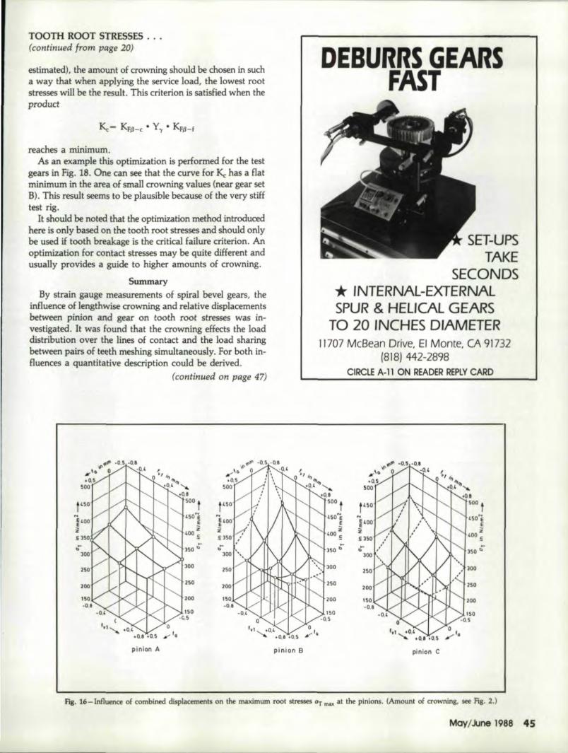
and offset (fa) do have a strong .influenoe. Pig.16 shows the root stresses measured. on the pi-nions for different combinations of fvl and fa.
lit becomes very clear how the gradients dependon the amount of crowning (pinions B -> C-> A).
1\ gear B gear Cgear A
~~-----~-.-.---~loll ~ I , S I " it
Ilheel toe heel toe heelloe (mill]
Fig. IS-Influence of axial displacements of the pinion (fvil on the contact pattern,
rvl
-0.B
-3 •.4
a.B
• In general, determination of the factor Kf6-f for a certaincombination of displacements (tv1• fa) and for a certainamount of crowning (Cc) is allowed by Fig. 17. By using,this factor the influence of the discussed parameters canbe estimated for a given practi.cal case.
Optimization 0.£ Lengthwise CrOwningFrom. the knowledge of the influence ,of crowning and
displacements discussed earlier. a criterion for the ,optimiza-tion of the crowning can be derived .. For a given design en-vironment with certain relative displacements (measured or
(continued on page 45)
TRUE DIMENSION GEAR ,IN;SPECTION'
Provides actual overban/pin. measure-
ment of anyhelical or
spur gear orspline with-
out the needof costly
setting masters ..
Provides vitalS.P-C. information.
Gage mvislonCAPACITY:
9" O.D.8" I.D.
niled toolS ppil,851 OHIO P1KE-CINCINN'A11, Otlllli 45245 - '151'3) 752:·&000
CIRCtJE A-15 ON READER IREPLY CARD,20 sear fechnology
TOOTH ROOT 'S~RESSES,..••(continued !rom page 20)
estimated), the amount of crowning should be chosen in sucha w.ay 'that when applying the service load, the lowest rootstresses will be the result. This criterion is satisfied when theproduct
reaches a minimum.As an example this optimization is performed for the test
gears in Fig. 18. One can see that the curve for ICc has a fIatminimum in the area of small crowning values (near gear setB). This result seems to, be plausible because of the very stifftest rig.
It should be noted that the optimization method introducedhere is only based on the tooth root. stresses and should onlybe used if tooth breakage is the c:ritka~ failure criterion. Anoptimization for contact stresses may be quite different andusually provides a guide to higher amounts of crowning.
SummazyBy strain gauge measurements ,of spir.al bevel gears, the
influence of lengthwise crowning and relative displac1!mentsbetween pinion and gear on tooth root stresses was in-vestigated. It was found that the crowning effects the loaddistribution over the lines of 'contact and the load sharingbetween pairs of teeth meshingsimul,t.aneously, For both in-fluenc:,es.a. quantitative description. could be derived.
(c·ontinued on page 47)
SET-UPSTAKE
SECO,NDS* I,NTERNAlc-EXTERN'ALSPUR & HELICAL GEARS
ro 20 INCHES DIA_METER'11707 Mc8ean Drive, EI Monte, CA 9173.2
1818) 442-.2898OIRCLE .A~1111aNi RE.ADER R,EP,lV CARD
~o J ,~ . .....0,' "".O,S
1
500 t1'501, z1'00 '5..l5D"
250
250' IZOOZOO 150
pinion A
if>'I> ·0.5,.0.•... '" ~ 0 I .0.,.0,5·
500
..~~oo I
~Ii J50
p1nlon C
Fig. 16-Influence of combined displacements on the maximum root stresses at mu at the pinions. (Amounl of crowning, see Fig. 2.)

Rates: Cl'assified Display-per inch (mini·mum 3,") 1X.-$1i20, 3X·$110, 6X-$100. Typewill be' sel to advertiser's layout or GearTechnology will set type at no extra charge.Word Count: 35 characters per line'., 7 linesper inch.
P-yment: Full payment must accompanyclassified ads. Mail copy 10, Gear Technology.P.O. Box 1426, IEIk.Grove Village, IL. 60007.Agency Commlssloll': No agency commlsionen classifieds.
Materials ID'eadUne: Ads must be receivedby Ihe 25th of the month, two months priorto publication. Acceptance: PublJsherreserves ~he right to accept or rejectclassified advertisements ,al his discretion.
COMPUTER AIDS
GEAR EST ATiNGThe COSTIMATOR® computer
aided cost estimati ngl system insuresspeed and consistency lin the difficulttask of estimating' the costs .o~ a'lltypes of gears.
Used by small shops and Fortune500 companies throughout thecountry ..
For compl'et,e :informationcontact us today.
M'anutactur,erSI Technologies, Inc.59G Interstate Dr.
West Springfie'ld,. MA 01089(413) 733-191]2
CIRCLE A.-16 ON READER REPLYCARD
GEARS ..SPLINESDESIGN AND TOOUING
.' Custom gear design including non-standar,d pressure angles for morestrength. .
., P,rograms to! enter tooling data in-to computer flies and search fOl' ex.-istingl cutters to cuta new gear orspline.
'. Gearing computer software forsale.
I! Consulting: services for gear andspline problems. .
VAN GERPEN-REECE ENGINEERING1502 Grand Blvd.
Cedar IFall's, Iowa 50613(319): 266 4674
CIRCLE A·27 ON READER REP,lY CARD
'GIEAR CALCULATI'O'NPIROG RA.M!SFO:R.TIH E
'GIEAR IMANIUFACTURERliN EXPENISIIVE., EASY TO RUNI
O'N IBMi COMIP'ATIBLES
IEXTERNAlIINTERNAl
INCHI (lOP)METRIC (Modi.)
SPURHELlCAt
S1I"RAIGHi BEVEL 1104)SPIRAl. BEVEl. '16 & 27 GRD'
BLANK AND SUMMARU~SFor Brochure' and !More Information
CALL. OR WfHTEUN,IVERSAL GEAR 00. INC.
p.a.Box A.G., Anza, CA 92306{114} 763-4616
CIRCLE A·17 'ON READER IREPLYCAR.D
REBUILDING
IHo.B:BE:R IREBUIL'D'IING,SPECIIALISTS
H'aving trouble meetingl todays de-mand quality control tolerances?Let our factory trained and ex-perlenced staff return yourmachine to optimum operatingcondit,ion.We specialize i;n repairing,rebuilding and mode.rnioting allmakes of hobbers.
• Cleveland IRigidhobber:s-Goul'd & Eberhardt• Sarber Colman
PIl,E,SS:~ATION I,NC.522 Cottage Grove IRoadIBloomfield, Oonn. 06002
(203) 24.2-8525,
CIRCLE A-2S ON IREAlDER' IREPtY CARD
,Bring in new customers for your business by advertising inGEAR TECHNOLOGY. The JournaJ of Gear Manufacturing.
Call (312)1 437~
46 Gear technology
@(g(g)[gjlJ~(g5C={]?tI~,/1U-.
GEAR DESIGNtPc~Al YSIS tor IBM PC & I
compatibles. GEARCAlC ($995): design op-timum spur & heli.cal gearsets from appli-'cation data .. AGMA218 ($1495): calculatepitting and 'bendingl fatigue lives peE AGMAStd. 218dl1. SCORING + ($49'5):analyze/plotscoring& wear pro-babilities. Fast. menu-driven pro-grams work as one system (oombin.ad pnce$2495,), do extensive' error-checking. Comprehensi,ve manuals(theory. operation, examples) in-cluded. Demo. avail'able. GEAflTECHSoftware, Inc., 1017 Pomona Ave.,AJbaI'llY,.CA94706 (415) 524-0668.
CIRCUE A-18 'ON READER REPLY CARO
SUBCONTRACT
GEAR TOO'TH GRINDING& HONING ONLY
IPrMuction OuanUUes3/4" P.O. to 27.5" IFI.O.:3.5 IO.P. and 11" Face
Gear Tooth FhlllshlnglIs 'our 'Only Business
We have no turning,. hoooing orshaping ,capability
.AlILEGHIENY IGEAIR CORP.
CIRCLE A·23 ON READER REP,lY CARD
There's stilll time ...order cl'osingi date for aclasslfled ad in the JulylAugustissue is May 1!Oth.

AmAs.encanas...,~SAlES IMAINA.GEA with 14 years ex-
perience seeking manufacturing posi·tlon In gear rel'ated Industry. ProcesseXl)6rience in hobbing, shaping, grind~ing and inspection ot spu r and helicalgears. Resume and reIerences uponrequest. Willing, to refocatefor the rightopponunity.
Send reply to: Box. CT,Gear Jechnolog,y,P.O. Box, 1!426, -Elk,Grove,IL60007
trs true. our Consumer Information Catalog is filled withbooklets that can answer 'the questions Americanconsumers ask. most.
To satisfy every appetite. (he Consumer Information Centerputs together this helpful Catalog quarterly containingmore than 200 federal publications you can order. 11'5 free.and so are almost half of the booklets it lists on subjectslike nutrition. money management. health and federalbenefits.
So get a slice of American opportunity. Write 'today for yourfree Catalog:
Consumer Information CenterDepartment Aij Pueblo, Colorado 8,1009
u.s. Gc:neral Services AdmlnlstraLion
TOOTH ROOT STRESSES ...(continued from page 45)
-1.0 -0.5 o 0.5 1.0tlt_vl
-1.5
I 1,3
1' tI u 1,2+---'1:---+---+~ :
~~ I, '-R:::::~9<:::-1--1,""u,~~ ,.O-l<,:......-:....:.:...-r----I---.:CJ"'iI
"'-u,:..:
B gear set AD.e+-----t----+---;
c1.6
Kf~_f -
1,81 2c~/b.l000 -
3o
In the case of relative displacements, deviations in pinionmounting distance and in offset have the strongest influenceon the root stresses. A method was introduced to determinethe increase or decrease of maximum stresses that have tobe expected tor a combination of certain values of theseparameters ..Further, a optimization criterion was derived thatallows finding the amount of lengthwise crowning produc-ing the lowest root stresses for a certain service condition.
References1. WINTER,. H., PAUl, M. "Influence of Relative Displacements
Between Pinion and Gear on Tooth Root Stresses of Spiral BevelGears." Gear Technology, July/August, 1985.
2. JARAMILl:O, T.J. "Deflections and Moments due toa Con-
F.[g. HI- Optimization of lengthwise crowning.
centrated Load on a Cantilever Plate of Infinite length." Jour-nal of Applied Mechanics, VoL ]7, Trans., ASME, Vol. 72 1950,S. 67-72, 342-343.
3.WELLAUER, E.J., SEIREG, A. "Bending Strength of Gear Teethby Cantilever Plate Theory." Journal of Engineering for In-dustry. Trans. AS ME,. Aug, 1960, S ...213-222.
4. AGMA.2003 - A86: Standard tor Rating ,the Pitting Resistanoeand Bending Strength of Cenerated Straight Bevel, Zerol Beveland Spiral Bevel Gear Teeth, 1986.
S. DIN 3991: Tragfahigkeitsberechnung von Kegelradem oboeAchsversetzung: Normentwurf, 1986.
6, COLEJ:vlAN, W. "Improved Method for Estimating Faligue Lifeof Bevel and Hypoid Gears." SAE Quarterly Transactions, Vol.6, No.2, 1952.-
'7, COLEMAN, W. "Effect of Mounting Displacements 001'1 Beveland Hypoid Gear Tooth Strength." SAE-Paper 75 01 51. 1975.
May/June 1988 47