Tool Integration with Triple Graph Grammars - A Survey · Developers are assigned to a specific...
38
Tool Integration with Triple Graph Grammars - A Survey Alexander K¨ onigs, Andy Sch¨ urr 1 Real-Time Systems Lab Darmstadt University of Technology D-64283 Darmstadt, Germany Abstract Nowadays, typical software and system engineering projects in various industrial sectors (automo- tive, telecommunication, etc.) involve hundreds of developers using quite a number of different tools. Thus, the data of a project as a whole is distributed over these tools. Therefore, it is neces- sary to make the relationships of different tool data repositories visible and keep them consistent with each other. This still is a nightmare due to the lack of domain-specific adaptable tool and data integration solutions which support maintenance of traceability links, semi-automatic consis- tency checking as well as update propagation. Currently used solutions are usually hand-coded one-way transformations between pairs of tools. In this article we present a rule-based approach that allows for the declarative specification of data integration rules. It is based on the formalism of triple graph grammars and uses directed graphs to represent MOF-compliant (meta) models. As a result we give an answer to OMG’s request for proposals for a MOF-compliant “queries, views, and transformation” (QVT) approach from the “model driven application development” (MDA) field. Keywords: tool integration, model integration, triple graph grammars, QVT, MDA 1 Introduction Development processes of complex system engineering projects nowadays typ- ically involve hundreds of geographically distributed developers. Commonly used process models (e.g. waterfall model, Rational Unified Process, V-model) subdivide these processes into distinct interrelated development phases or workflows. Developers are assigned to a specific phase or workflow; they often 1 Email: {koenigs|schuerr}@es.tu-darmstadt.de Electronic Notes in Theoretical Computer Science 148 (2006) 113–150 1571-0661 © 2006 Elsevier B.V. www.elsevier.com/locate/entcs doi:10.1016/j.entcs.2005.12.015 Open access under CC BY-NC-ND license.
Transcript of Tool Integration with Triple Graph Grammars - A Survey · Developers are assigned to a specific...
Tool Integration with Triple Graph Grammars
- A Survey
Alexander Konigs, Andy Schurr1
Real-Time Systems LabDarmstadt University of Technology
D-64283 Darmstadt, Germany
Abstract
Nowadays, typical software and system engineering projects in various industrial sectors (automo-tive, telecommunication, etc.) involve hundreds of developers using quite a number of differenttools. Thus, the data of a project as a whole is distributed over these tools. Therefore, it is neces-sary to make the relationships of different tool data repositories visible and keep them consistentwith each other. This still is a nightmare due to the lack of domain-specific adaptable tool anddata integration solutions which support maintenance of traceability links, semi-automatic consis-tency checking as well as update propagation. Currently used solutions are usually hand-codedone-way transformations between pairs of tools. In this article we present a rule-based approachthat allows for the declarative specification of data integration rules. It is based on the formalismof triple graph grammars and uses directed graphs to represent MOF-compliant (meta) models. Asa result we give an answer to OMG’s request for proposals for a MOF-compliant “queries, views,and transformation” (QVT) approach from the “model driven application development” (MDA)field.
Keywords: tool integration, model integration, triple graph grammars, QVT, MDA
1 Introduction
Development processes of complex system engineering projects nowadays typ-ically involve hundreds of geographically distributed developers. Commonlyused process models (e.g. waterfall model, Rational Unified Process, V-model)subdivide these processes into distinct interrelated development phases orworkflows. Developers are assigned to a specific phase or workflow; they often
1 Email: {koenigs|schuerr}@es.tu-darmstadt.de
Electronic Notes in Theoretical Computer Science 148 (2006) 113–150
1571-0661 © 2 006 Else vier B.V.
www.elsevier.com/locate/entcs
doi:10.1016/j.entcs.2005.12.015Open access under CC BY-NC-ND license.

System requirements
Doors
SW-Functionality
Matlab / Together
HW-Design
HDL Author
Function Test
CTE XL
ECU-Housing
Catia
Product Data
Windchill
Fig. 1. Different tools in one specific software system engineering process
make use of CASE tools which are specialized in supporting a specific taskand manipulating specific types of documents. Figure 1 depicts a small ex-ample of this kind, a subset of a tool chain that is used in various automotivesystems engineering projects. The functional and non-functional requirementsof a system are stored in the data-based requirements tool Doors. These re-quirements ask for software functionality which is specified and modeled inMatlab and Together. The hardware design of the system is done with HDLAuthor. Catia is used for computer-aided design, engineering, and manufac-turing. Functional tests are specified using CTE XL. Finally, the data of theentire project is managed with Windchill.
Thus, the development documents of a project as a whole are usually dis-tributed over proprietary data repositories of different tools. As the developerswork on these separated data repositories that evolve concurrently, they facethe risk of working on increasingly inconsistent sets of documents. Therefore,tool support is urgently needed to keep the data of separate tool repositoriesin a consistent state, taking sometimes rather domain-specific integrity con-straints into account. This kind of tool/data integration support has been a“hot research topic” for about 15 years now and is still not addressed satis-factorily.
One popular integration approach introduced in the past was based onso-called message servers as used in commercial products like HP-Soft-Bench[16] or ToolTalk [15]. These systems offered basic control- and event-oriented[4] integration mechanisms, but did not allow for the specification of functionaldependencies between documents. A more data-oriented approach was basedon so-called compatibility maps [17]. This approach worked on a commondatabase, but provided only poor support for the specification of functionaldocument dependencies. Other approaches introduced at about the same timemodeled whole project databases as attributed syntax trees and implementedconsistency checks as attribute evaluation rules. For instance Mercury [21]
A. Königs, A. Schürr / Electronic Notes in Theoretical Computer Science 148 (2006) 113–150114

offered some support for attribute value propagation from one document toanother one. Gandalf [19] and Centaur [3] used a more sophisticated versionof the concept of attributed syntax trees and supported arbitrarily nesteddocuments. The main disadvantage of all these approaches was the lack ofany tool support for consistency recovering data updates. To overcome thisdeficiency of standard attribute grammars based solutions attribute coupledgrammars [18] have been introduced. They use attribute evaluation rules ofone syntax tree to construct another syntax tree, i.e. another document. Asevere drawback of attribute coupled grammars as well as of the presenteddata integration approaches so far is that they are batch-oriented and unidi-rectional. They translate a source document into a target document, but notvice-versa. TransformGen [46] was a first attempt to regard source and targetdocuments in a bidirectional way. TransformGen semi-automatically gener-ated unidirectional and batch-oriented transformation tools for both directionsusing a single specification of related string grammars as input. This idea ofrelating grammars for different string/tree languages to graph languages hasbeen generalized and builds the basis for the integration approaches presentedin this paper. The initial work in this area has been done by Pratt, whointroduced the concept of pair grammars [38] already many years ago.
Recently, the tool/data integration problem has been re-addressed, butnot yet solved, by the Object Management Group (OMG) and its Request ForProposals (RFP) for a MOF-compliant “queries, view, and transformation”standard (QVT) [32]. The RFP requires first of all that OMG’s Meta-ObjectFacility (MOF) [33] is used as a basis. MOF is a standard modeling lan-guage specification for “defining, manipulating, and integrating meta-dataand data in a platform independent manner”. In this paper we give a surveyof a tool/data integration approach based on MOF and so-called triple graphgrammars with regard to the QVT-RFP. Triple graph grammars (TGGs) havebeen invented as a stand-alone declarative model integration formalism 10years ago [43]. It is topic of ongoing research activities to adopt TGGs to theworld of OMG standards [22]. It is the purpose of this paper to summarize thebasic ideas of the TGG-based tool integration approach using the terminologyof the OMG standard MOF and to relate this presentation to the previouslypublished formal definition of a rather simple form of TGGs. Thus, this paperis a combination of excerpts from [22] and [43]. TGGs have been adopted formigrating relational to object oriented database systems [20], for tool integra-tion in the IPSEN context [25], and for diagram consistency management inthe FUJABA project for instance [51].
For demonstration purposes we will use a running example that is relatedto a real-world automotive project. The project deals with the development of
A. Königs, A. Schürr / Electronic Notes in Theoretical Computer Science 148 (2006) 113–150 115
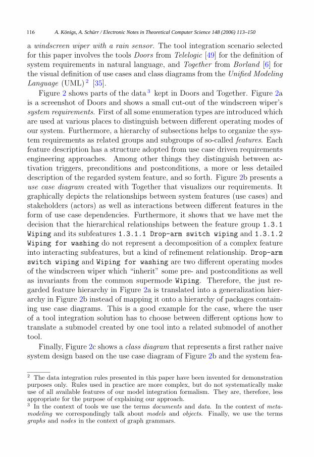
a windscreen wiper with a rain sensor. The tool integration scenario selectedfor this paper involves the tools Doors from Telelogic [49] for the definition ofsystem requirements in natural language, and Together from Borland [6] forthe visual definition of use cases and class diagrams from the Unified ModelingLanguage (UML) 2 [35].
Figure 2 shows parts of the data 3 kept in Doors and Together. Figure 2ais a screenshot of Doors and shows a small cut-out of the windscreen wiper’ssystem requirements. First of all some enumeration types are introduced whichare used at various places to distinguish between different operating modes ofour system. Furthermore, a hierarchy of subsections helps to organize the sys-tem requirements as related groups and subgroups of so-called features. Eachfeature description has a structure adopted from use case driven requirementsengineering approaches. Among other things they distinguish between ac-tivation triggers, preconditions and postconditions, a more or less detaileddescription of the regarded system feature, and so forth. Figure 2b presents ause case diagram created with Together that visualizes our requirements. Itgraphically depicts the relationships between system features (use cases) andstakeholders (actors) as well as interactions between different features in theform of use case dependencies. Furthermore, it shows that we have met thedecision that the hierarchical relationships between the feature group 1.3.1
Wiping and its subfeatures 1.3.1.1 Drop-arm switch wiping and 1.3.1.2
Wiping for washing do not represent a decomposition of a complex featureinto interacting subfeatures, but a kind of refinement relationship. Drop-arm
switch wiping and Wiping for washing are two different operating modesof the windscreen wiper which “inherit” some pre- and postconditions as wellas invariants from the common supermode Wiping. Therefore, the just re-garded feature hierarchy in Figure 2a is translated into a generalization hier-archy in Figure 2b instead of mapping it onto a hierarchy of packages contain-ing use case diagrams. This is a good example for the case, where the userof a tool integration solution has to choose between different options how totranslate a submodel created by one tool into a related submodel of anothertool.
Finally, Figure 2c shows a class diagram that represents a first rather naivesystem design based on the use case diagram of Figure 2b and the system fea-
2 The data integration rules presented in this paper have been invented for demonstrationpurposes only. Rules used in practice are more complex, but do not systematically makeuse of all available features of our model integration formalism. They are, therefore, lessappropriate for the purpose of explaining our approach.3 In the context of tools we use the terms documents and data. In the context of meta-modeling we correspondingly talk about models and objects. Finally, we use the termsgraphs and nodes in the context of graph grammars.
A. Königs, A. Schürr / Electronic Notes in Theoretical Computer Science 148 (2006) 113–150116

a)
Wiping
Drop-arm switch wiping Wiping for washing
Washing with wiping Washing
Wiper
Ignition
Drop-arm switch Pump
<<include>><<extend>>
<<include>>
b)
Wiping
DropArmSwitchWiping WipingForWashing
WashingWithWiping Washing
Wiper
Ignition
DropArmSwitch Pump
c)
Fig. 2. Example requirements, use case, and class diagram documents
A. Königs, A. Schürr / Electronic Notes in Theoretical Computer Science 148 (2006) 113–150 117

ture definitions of Figure 2a. In this case, we made the decision to introducean interface wrapper class for any (sensor/actuator) actor of the system andto implement each feature in the form of a separate class. Sensors send theirdata to the corresponding feature classes, whereas feature classes compute andpropagate the needed data to control all actuators. Furthermore, it is ratherobvious to translate generalization relationships between use cases into gen-eralizationships between classes, whereas it is a matter of debate whether thetranslation of extend and includes dependencies into aggregation of classes isthe most obvious solution. It is the topic of related ongoing research activitiesto come up with sets of more sophisticated domain-specific model mappingrules which support coevolution of system requirements and architectures.
In chapter 2 we explain our document and tool integration approach aspresented in [22]. We introduce meta-modeling as a well known technique fordescribing the structure of documents. We add the concept of triple graphgrammars in order to write down rules which declaratively describe correspon-dences between documents in order to integrate them. From these declarativerules we derive operational rules in chapter 3. These operational rules canbe applied in order to fulfill rather different integration tasks. In chapter 4we recall the formalism of triple graph grammars as presented in [43]. Wecontinue in chapter 5 by presenting OMG’s QVT request for proposals as apossibility to classify document and tool integration approaches. On this ba-sis, we introduce related approaches, and compare them with each other aswell as with our own approach. Finally, chapter 6 summarizes and concludesour paper, discusses open issues and future work.
2 Presentation of our approach
In this chapter we present our tool/data integration approach that allows forthe declarative specification of consistency checking and recovering integra-tion rules. We start by introducing meta-modeling as a well-known techniqueto specify the abstract syntax and static semantics of data kept in softwaresystem engineering tools. Furthermore, we use meta-modeling for declaringcorrespondence link types between the data repositories of different tools. Fi-nally, we introduce the idea of triple graph grammars for specifying declarativedata integration rules. We will see later on that these triple graph grammarrules may automatically be translated into different sets of operational modeltransformation rules which are then responsible for checking consistency ofmeta-models and propagating changes between related meta-models in all di-rections.
A. Königs, A. Schürr / Electronic Notes in Theoretical Computer Science 148 (2006) 113–150118
1
0..*
0..*
1
trg
0..1
0..*
1
0..*
src
Container
Package
-name:String
Diagram
UseCase
-name:String
Relationship
Generalization
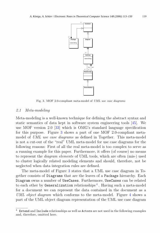
Fig. 3. MOF 2.0-compliant meta-model of UML use case diagrams
2.1 Meta-modeling
Meta-modeling is a well-known technique for defining the abstract syntax andstatic semantics of data kept in software system engineering tools [45]. Weuse MOF version 2.0 [33] which is OMG’s standard language specificationfor this purpose. Figure 3 shows a part of one MOF 2.0-compliant meta-model of UML use case diagrams as defined in Together. This meta-modelis not a cut-out of the “real” UML meta-model for use case diagrams for thefollowing reasons: First of all the real meta-model is too complex to serve asa running example for this paper. Furthermore, it offers (of course) no meansto represent the diagram elements of UML tools, which are often (mis-) usedto cluster logically related modeling elements and should, therefore, not beneglected when data integration rules are defined.
The meta-model of Figure 3 states that a UML use case diagram in To-gether consists of Diagrams that are the leaves of a Package hierarchy. EachDiagram owns a number of UseCases. Furthermore, UseCases can be relatedto each other by Generalization relationships 4 . Having such a meta-modelfor a document we can represent the data contained in the document as aUML object diagram which conforms to the meta-model. Figure 4 shows apart of the UML object diagram representation of the UML use case diagram
4 Extend and Include relationships as well as Actors are not used in the following examplesand, therefore, omitted here.
A. Königs, A. Schürr / Electronic Notes in Theoretical Computer Science 148 (2006) 113–150 119

document of our running example (cf. Figure 2b). Accordingly, we can writea meta-model for requirements documents stored in Doors.
:Package
:Diagram
:UseCase
:Generalization :Generalization
:UseCase :UseCase
name = "WashingWiping"
name = "Wiping"
name = "DropArmSwitchWiping" name = "WipingForWashing"
Fig. 4. Part of the UML object diagram representation of the UML use case diagram
The basic idea of our tool/data integration approach is to create and main-tain correspondence links (traceability links) between elements of the differenttools’ data repositories. Using the meta-models of the tools that we want tointegrate with each other we can write a meta-model for the correspondencelinks as well. This meta-model maps elements from the meta-model of onetool to elements of the meta-model of the other tool and vice-versa. Figure 5depicts the three meta-models that we need for declaring correspondence linksin our windscreen wiper project.
Figure 5a shows the meta-model for requirements documents. Figure 5crecalls the meta-model for use case diagrams. Finally, Figure 5b uses bothtools’ meta-models in order to declare the needed correspondence link types.The imported classes from the to be integrated meta-models defined in packageRequirementsDocument and UseCaseDocument are rendered in gray in thepackage IntegrationSchema.
In our approach we demand that to be integrated meta-models are or-ganized as shown in Figure 6. The meta-model of each tool is defined ina separate package which may contain subpackages if needed. Each of thesepackages may contain any MOF 2.0-compliant meta-model describing the datastructure of a tool. Additionally, we have a third hierarchy of packages markedwith the stereotype Integration. These packages contain the meta-model ofthe needed correspondence links. We demand that each correspondence linktype declaration must match the one depicted in Figure 7. The declared linktype may have an arbitrary name and must be marked with the stereotypeIntegration. This stereotype indicates the fact that we currently (mis-)useUML classes stereotyped with Integration to define MOF 2.0 associations,when we use a standard UML 1.x CASE tool for the definition of meta-models.
A. Königs, A. Schürr / Electronic Notes in Theoretical Computer Science 148 (2006) 113–150120

0..1
0..*
0..*
1
trg
1
0..*
src
Requirement
FeatureGroup
-name:String
Feature
-name:String
Dependency
RequirementsDocumenta)
<<Integration>>
FeatureGroupPackageRelation
<<Integration>>
FeatureUseCaseRelation
<<Integration>>
DependencyRelationshipRelation
FeatureGroup
-name:String
Feature
-name:String
Dependency
UseCase
-name:String
Relationship
Package
-name:String
IntegrationSchemab) 1
0..*
0..*
1
trg
0..1
0..*
1
0..*
src
Container
Package
-name:String
Diagram
UseCase
-name:String
Relationship
Generalization
UseCaseDocumentc)
Fig. 5. Tools’ and integration meta-models
<<import>><<import>>
<<Integration>>
IntegrationSchemaSchema Tool A Schema Tool B
Fig. 6. Organization of meta-models in our approach
The implementation of a proper MOF 2.0 editor with direct support for allmeta-modeling concepts is almost completed as a new plugin for the UMLCASE tool framework FUJABA [30]. It will be used in the future for meta-modeling purposes and offer more sophisticated support for organizing meta-models in packages, specializing associations, etc.
Any (MOF) association like the one depicted in Figure 7 has exactly twoends. The ends point to the corresponding elements from the tools’ meta-models. Each end may carry a multiplicity. As usual these multiplicitiesspecify how many elements from tool B correspond to one element from tool Aand vice versa. If no multiplicity is provided for an association end we assumethe multiplicity 1 as default. These multiplicities are later on used to checkconsistency and completeness of (semi-)automatically created correspondencelinks. In our running example the implicitly defined multiplicity constraintsrequire e.g. that all requirement document instances of class FeatureGroup,Feature, and Dependency are mapped onto one and only one instance ofthe corresponding classes Package, UseCase, and Relationship of a use casedocument.
A. Königs, A. Schürr / Electronic Notes in Theoretical Computer Science 148 (2006) 113–150 121

11
A B<<Integration>>
ABRelation
<<Integration>>
AnotherRelation
Fig. 7. Prototype of a correspondence link type declaration
Additionally, a link type declaration may inherit from another link typedeclaration such that we are able to construct modeling-domain specific hier-archies of correspondence link types. Please notice that MOF 2.0 now offersthe therefore required means for generalization and refinement of associationswhich are not discussed in this paper. They are of great importance for the def-inition of reusable and adaptable meta-model integration specifications. Fora discussion of still open problems with the semantics of generalization andrefinement (redefinition and subsetting) of MOF 2.0 associations the reader isreferred to [1].
2.2 Specification of integration rules
Having declared the types of the correspondence links we now need a lan-guage for specifying the conditions that must hold in order to consider acorrespondence link as consistent. One obvious possibility is to use a tex-tual language like the Object Constraint Language (OCL) [34] for that pur-pose. For example, if we want to state that a correspondence link of typeFeatureGroupPackageRelation is consistent if the name of the attachedFeatureGroup with the identifier fg is the same as the name of the at-tached Package with the identifier p, we would write something like fg.name =
p.name. This is straight-forward and easy to understand. Let us now regard asecond example. We would like to state that a correspondence link of the typeFeatureUseCaseRelation is consistent if the name of the attached Feature
with the identifier f is the same as the name of the attached UseCase withthe identifier uc and f is contained in a FeatureGroup fg which is linked to aPackage p by a correspondence link of type FeatureGroupPackageRelation
fgpr, and the Package p finally contains uc. In a textual constraint languagethe needed constraint definition looks like f.name = f.fg.fgr.p.uc.name.Although the regarded constraint is still very basic this expression is harderto imagine and to understand, especially without a figure which we omit here
A. Königs, A. Schürr / Electronic Notes in Theoretical Computer Science 148 (2006) 113–150122
intentionally. The situation gets worse if the condition whether a correspon-dence link is consistent or not becomes more complex. The way out is to use agraphical notation for the definition of consistency conditions. Only parts of acondition which cannot reasonably be expressed in a graphical way should stillbe expressed textually. This concerns conditions like the equality of names forinstance.
About 30 years ago graph grammars have been invented for the purposeto define the syntax and the static semantics of visual languages graphically[37,42]. Used in combination with meta-models they exactly offer the ap-propriate means to define the constraints which determine the consistency ofour correspondence links. Graph grammars or, more precisely, programmedgraph transformation systems have been adapted and implemented by variousintegrated visual programming environments like PROGRES [47], FUJABA[30], AGG [48], or DiaGen [26]. These environments have been and still aresuccessfully used as meta-CASE tools for prototyping integrated sets of CASEand programming tools [29]. For further details concerning various forms ofgraph grammars, available implementations, and related success stories thereader is referred to the “Handbooks of Graph Grammars and Computingby Graph Transformation [11,12] as well as to the proceedings of two work-shops on “Applications of Graph Transformations with Industrial Relevance”[31,36].
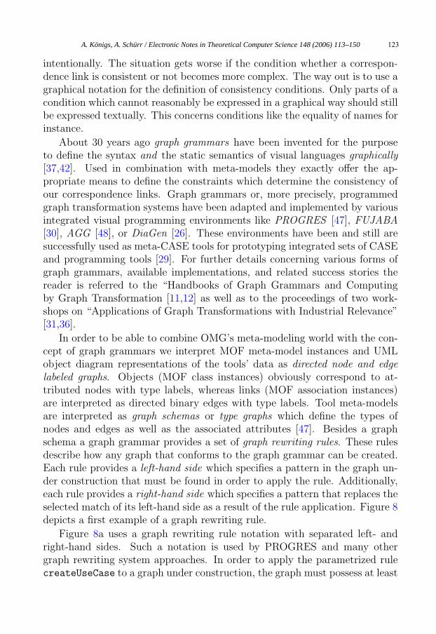
In order to be able to combine OMG’s meta-modeling world with the con-cept of graph grammars we interpret MOF meta-model instances and UMLobject diagram representations of the tools’ data as directed node and edgelabeled graphs. Objects (MOF class instances) obviously correspond to at-tributed nodes with type labels, whereas links (MOF association instances)are interpreted as directed binary edges with type labels. Tool meta-modelsare interpreted as graph schemas or type graphs which define the types ofnodes and edges as well as the associated attributes [47]. Besides a graphschema a graph grammar provides a set of graph rewriting rules. These rulesdescribe how any graph that conforms to the graph grammar can be created.Each rule provides a left-hand side which specifies a pattern in the graph un-der construction that must be found in order to apply the rule. Additionally,each rule provides a right-hand side which specifies a pattern that replaces theselected match of its left-hand side as a result of the rule application. Figure 8depicts a first example of a graph rewriting rule.
Figure 8a uses a graph rewriting rule notation with separated left- andright-hand sides. Such a notation is used by PROGRES and many othergraph rewriting system approaches. In order to apply the parametrized rulecreateUseCase to a graph under construction, the graph must possess at least
A. Königs, A. Schürr / Electronic Notes in Theoretical Computer Science 148 (2006) 113–150 123

:Diagram
:Diagram :Diagram :UseCase
<<new>>
:UseCase<<new>>
name = x
name = x::=
a)
b)
createUseCase( x : String )
createUseCase( x : String )
Fig. 8. Example of a graph rewriting rule
one Diagram node. After one of the possible matches of the rule’s left-handside has been selected the difference between the rule’s right-hand side andits left-hand side is added to the graph 5 . After rule application the graphhas got a new UseCase node with a name attribute value provided by therule’s parameter x. This new UseCase is linked to the previously selectedDiagram node. Figure 8b depicts the same rule in a collapsed style as usedin FUJABA. The left-hand side of such a collapsed rule is determined by thenodes and edges without any stereotype 6 , the right-hand side consists of allunmarked nodes and edges as well as of all nodes and edges marked with thestereotype new. We use the collapsed style in the following. It is the preferrednotation as long as monotonic rules are used which do not delete any nodesand edges from the graph.
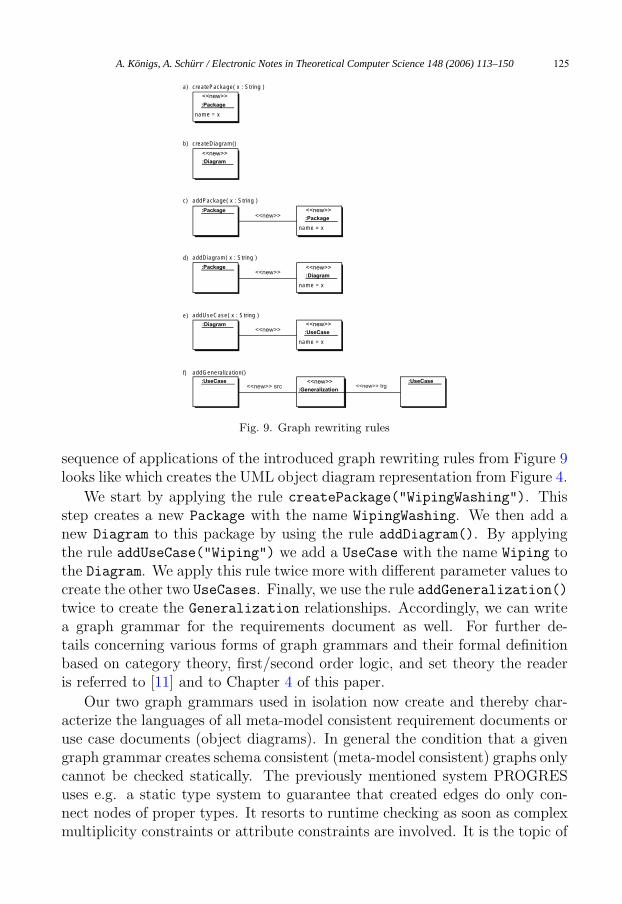
As an example we now present a subset of the rules of a graph grammarfor our UML use case diagrams. We recall that the meta-model shown inFigure 3 acts as the graph’s schema. Figure 9 lists the needed graph grammarrules. Please notice that we have used two rules with an empty left-hand sideto define the additionally needed start graphs or axioms of such a grammar.These rules may only be applied to the empty graph thereby creating a graphwhich consists either of one Package or one Diagram node only.
The rule createPackage allows for the creation of a new Package with theprovided name. Accordingly, the rule createDiagram allows for the creationof a new Diagram. The rule addPackage describes the addition of a newPackage which is part of an existing Package. Correspondingly, addDiagramdescribes the addition of a new Diagram which is part of an existing Package.By using the rule addUseCase we can add new UseCases to existing Diagrams.Finally, we can connect existing UseCases by Generalization relationshipsby applying the rule addGeneralization. Figure 10 demonstrates how a
5 Deletion of nodes and edges is handled by removing the difference of a rule’s left-handside and its right-hand side from the regarded graph.6 In general, nodes and edges marked with the stereotype delete also belong to a rule’sleft-hand side, but not to its right-hand side.
A. Königs, A. Schürr / Electronic Notes in Theoretical Computer Science 148 (2006) 113–150124
<<new>>
:Package
<<new>>
:Diagram
:Package <<new>>
:Package
:Package <<new>>
:Diagram
:Diagram <<new>>
:UseCase
:UseCase <<new>>
:Generalization
:UseCase<<new>> src
<<new>>
<<new>>
<<new>>
<<new>> trg
createPackage( x : String )
createDiagram()
addPackage( x : String )
addDiagram( x : String )
addUseCase( x : String )
addGeneralization()
a)
b)
c)
d)
e)
f)
name = x
name = x
name = x
name = x
Fig. 9. Graph rewriting rules
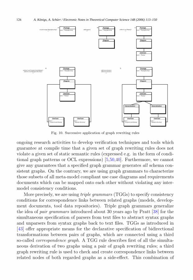
sequence of applications of the introduced graph rewriting rules from Figure 9looks like which creates the UML object diagram representation from Figure 4.
We start by applying the rule createPackage("WipingWashing"). Thisstep creates a new Package with the name WipingWashing. We then add anew Diagram to this package by using the rule addDiagram(). By applyingthe rule addUseCase("Wiping") we add a UseCase with the name Wiping tothe Diagram. We apply this rule twice more with different parameter values tocreate the other two UseCases. Finally, we use the rule addGeneralization()twice to create the Generalization relationships. Accordingly, we can writea graph grammar for the requirements document as well. For further de-tails concerning various forms of graph grammars and their formal definitionbased on category theory, first/second order logic, and set theory the readeris referred to [11] and to Chapter 4 of this paper.
Our two graph grammars used in isolation now create and thereby char-acterize the languages of all meta-model consistent requirement documents oruse case documents (object diagrams). In general the condition that a givengraph grammar creates schema consistent (meta-model consistent) graphs onlycannot be checked statically. The previously mentioned system PROGRESuses e.g. a static type system to guarantee that created edges do only con-nect nodes of proper types. It resorts to runtime checking as soon as complexmultiplicity constraints or attribute constraints are involved. It is the topic of
A. Königs, A. Schürr / Electronic Notes in Theoretical Computer Science 148 (2006) 113–150 125
:Package
:Diagram
:UseCase
:UseCase :UseCase
:Package
:UseCase
:Generalization
:UseCase
:Generalization
:Package
:Diagram
:UseCase
:Package
:Diagram
:UseCase
:Package
:Diagram
createPackage("WipingWashing")=>
addDiagram()=>
addUseCase("Wiping")=>
addUseCase("DropArmSwitchWiping")addUseCase("WipingForWashing")
=>
addGeneralization()addGeneralization()
=>
name = "WipingWashing" name = "WipingWashing" name = "WipingWashing"
name = "Wiping"
name = "WipingWashing"
name = "Wiping"
name = "DropArmSwitchWiping"
name = "WipingForWashing"
name = "WipingWashing"
name = "Wiping"
name = "DropArmSwitchWiping"
name = "WipingForWashing"
a) b) c)
e) f)
Fig. 10. Successive application of graph rewriting rules
ongoing research activities to develop verification techniques and tools whichguarantee at compile time that a given set of graph rewriting rules does notviolate a given set of static semantic rules (expressed e.g. in the form of condi-tional graph patterns or OCL expressions) [5,50,40]. Furthermore, we cannotgive any guarantees that a specified graph grammar generates all schema con-sistent graphs. On the contrary, we are using graph grammars to characterizethose subsets of all meta-model compliant use case diagrams and requirementsdocuments which can be mapped onto each other without violating any inter-model consistency conditions.
More precisely, we are using triple grammars (TGGs) to specify consistencyconditions for correspondence links between related graphs (models, develop-ment documents, tool data repositories). Triple graph grammars generalizethe idea of pair grammars introduced about 30 years ago by Pratt [38] for thesimultaneous specification of parsers from text files to abstract syntax graphsand unparsers from syntax graphs back to text files. TGGs as introduced in[43] offer appropriate means for the declarative specification of bidirectionaltransformations between pairs of graphs, which are connected using a thirdso-called correspondence graph. A TGG rule describes first of all the simulta-neous derivation of two graphs using a pair of graph rewriting rules; a thirdgraph rewriting rule is used to check and create correspondence links betweenrelated nodes of both regarded graphs as a side-effect. This combination of
A. Königs, A. Schürr / Electronic Notes in Theoretical Computer Science 148 (2006) 113–150126
three graph rewriting rules which have to be applied simultaneously was thereason for choosing the name “triple graph grammar”.
Applying the idea of triple graph grammars as it is to practice in orderto keep documents consistent with each other is utopistic. This would meanthat all development documents or models would evolve simultaneously. Ad-ditionally, all documents would be consistent all the time. Unfortunately,the situation is usually as follows: We have lots of documents that evolveconcurrently. We would like to automatically create correspondence links fortraceability purposes and to automatically fix any inconsistencies from time totime when a consistent state of the project database is needed. Thus, TGGsare declarative specifications of integration rules which are not directly usefulfor tool integration purposes. From these declarative specifications operationalgraph rewriting rules can be derived automatically. These operational graphrewriting rules are then used to realize needed data/tool integration services(cf. Chapter 3).
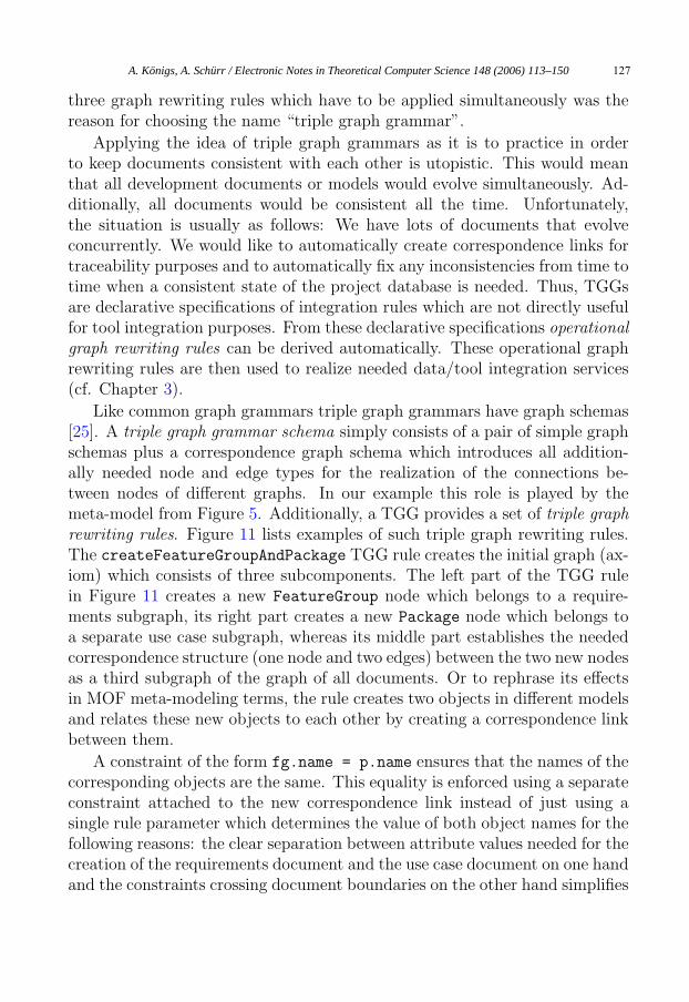
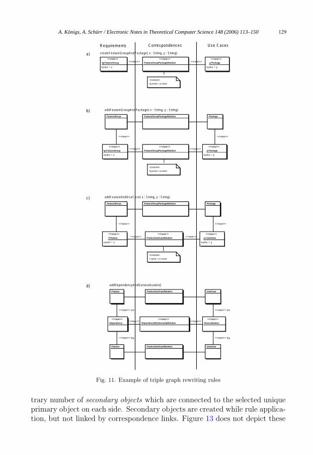
Like common graph grammars triple graph grammars have graph schemas[25]. A triple graph grammar schema simply consists of a pair of simple graphschemas plus a correspondence graph schema which introduces all addition-ally needed node and edge types for the realization of the connections be-tween nodes of different graphs. In our example this role is played by themeta-model from Figure 5. Additionally, a TGG provides a set of triple graphrewriting rules. Figure 11 lists examples of such triple graph rewriting rules.The createFeatureGroupAndPackage TGG rule creates the initial graph (ax-iom) which consists of three subcomponents. The left part of the TGG rulein Figure 11 creates a new FeatureGroup node which belongs to a require-ments subgraph, its right part creates a new Package node which belongs toa separate use case subgraph, whereas its middle part establishes the neededcorrespondence structure (one node and two edges) between the two new nodesas a third subgraph of the graph of all documents. Or to rephrase its effectsin MOF meta-modeling terms, the rule creates two objects in different modelsand relates these new objects to each other by creating a correspondence linkbetween them.
A constraint of the form fg.name = p.name ensures that the names of thecorresponding objects are the same. This equality is enforced using a separateconstraint attached to the new correspondence link instead of just using asingle rule parameter which determines the value of both object names for thefollowing reasons: the clear separation between attribute values needed for thecreation of the requirements document and the use case document on one handand the constraints crossing document boundaries on the other hand simplifies
A. Königs, A. Schürr / Electronic Notes in Theoretical Computer Science 148 (2006) 113–150 127
later-on the derivation of operational graph rewriting rules from TGG rules,significantly.
The second and third TGG rule of Figure 11 add related subcomponentsof class FeatureGroup or Feature and Package or UseCase to an alreadyrelated pair of objects of class FeatureGroup and Package. Finally, therule addDependencyAndGeneralization is responsible for creating a pair ofDependency and Generalization links that connect already related pairs ofobjects of the appropriate classes. Please notice that we have omitted theadditional negative rule application condition that guarantees that not morethan one Dependency link (UseCase link) is created between a given pair ofFeature objects (UseCase objects). Multiple links of this kind between asingle pair of objects are not only useless from the local point of view of therelated models, but would also cause problems for the automatic creation ofcorrespondence links. It would be unclear how to connect parallel links in onemodel to the corresponding parallel links in the other model.
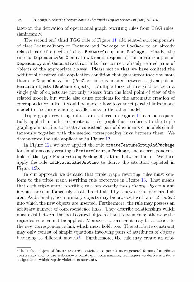
Triple graph rewriting rules as introduced in Figure 11 can be sequen-tially applied in order to create a triple graph that conforms to the triplegraph grammar, i.e. to create a consistent pair of documents or models simul-taneously together with the needed corresponding links between them. Wedemonstrate the rule application in Figure 12.
In Figure 12a we have applied the rule createFeatureGroupAndPackage
for simultaneously creating a FeatureGroup, a Package, and a correspondencelink of the type FeatureGroupPackageRelation between them. We thenapply the rule addFeatureAndUseCase to derive the situation depicted inFigure 12b.
In our approach we demand that triple graph rewriting rules must con-form to the triple graph rewriting rule prototype in Figure 13. That meansthat each triple graph rewriting rule has exactly two primary objects a andb which are simultaneously created and linked by a new correspondence linkabr. Additionally, both primary objects may be provided with a local contextinto which the new objects are inserted. Furthermore, the rule may possess anarbitrary number of correspondence links. They describe relationships whichmust exist between the local context objects of both documents; otherwise theregarded rule cannot be applied. Moreover, a constraint may be attached tothe new correspondence link which must hold, too. This attribute constraintmay only consist of simple equations involving pairs of attributes of objectsbelonging to different models 7 . Furthermore, the rule may create an arbi-
7 It is the subject of future research activities to permit more general forms of attributeconstraints and to use well-known constraint programming techniques to derive attributeassignments which repair violated constraints.
A. Königs, A. Schürr / Electronic Notes in Theoretical Computer Science 148 (2006) 113–150128
<<new>>
fg:FeatureGroup
:Package
<<new>>
:FeatureGroupPackageRelation
:FeatureGroup :FeatureGroupPackageRelation
<<new>>
p:Package
:FeatureGroup :Package:FeatureGroupPackageRelation
<<new>>
f:Feature
<<new>>
uc:UseCase
<<new>>
:FeatureUseCaseRelation
:Feature
:Feature
<<new>>
:Dependency
:FeatureUseCaseRelation
<<new>>
:DependencyRelationshipRelation
:FeatureUseCaseRelation
:UseCase
:UseCase
<<new>>
fg:FeatureGroup
<<new>>
:FeatureGroupPackageRelation
<<new>>
p:Package
<<new>>
:Generalization
<<new>><<new>>
<<new>> trg
<<new>> src
<<new>><<new>>
<<new>> trg
<<new>> src
<<new>><<new>>
<<new>><<new>>
<<new>>
<<new>>
<<new>>
<<new>>
Constraint:
fg.name = p.name
Constraint:
f.name = uc.name
Constraint:
fg.name = p.name
createFeatureGroupAndPackage( x : String, y : String)
addDependencyAndGeneralization()
addFeatureGroupAndPackage( x : String, y : String)
addFeatureAndUseCase( x : String, y : String)
name = x
name = x
name = x name = y
name = y
name = y
a)
b)
c)
d)
Use CasesCorrespondencesRequirements
Fig. 11. Example of triple graph rewriting rules
trary number of secondary objects which are connected to the selected uniqueprimary object on each side. Secondary objects are created while rule applica-tion, but not linked by correspondence links. Figure 13 does not depict these
A. Königs, A. Schürr / Electronic Notes in Theoretical Computer Science 148 (2006) 113–150 129

fg:FeatureGroup fgr:FeatureGroupPackageRelation
fg:FeatureGroup fgr:FeatureGroupPackageRelation
fucr:FeatureUseCaseRelation
p:Package
p:Package
uc:UseCasef:Feature
createFeatureGroupAndPackage("WipingWashing", "WipingWashing")||V
addFeatureAndUseCase("Wiping", "Wiping")||V
a)
b)
name = "WpingWashing" name = "WipingWashing"
name = "WipingWashing" name = "WipingWashing"
name = "Wiping" name = "Wiping"
Use CasesRequirements Correspondences
Fig. 12. Application of triple graph rewriting rules
<<new>>
abr:ABRelation
<<new>>
b:B
<<new>>
a:A <<new>><<new>>
Constraint:
<Constraint-Expression>
local contextlocal context
inter-documentrelationships
Fig. 13. Prototype of a triple graph rewriting rule
additional objects which are sometimes needed, when a single object of onemodel is translated into a set of related objects in the other model.
Finally, our TGG rules may never delete any objects for the following tworeasons: First of all, TGGs are used to generate languages of consistent pairsof documents and not to manipulate pairs of documents, i.e. deletion of ob-jects and edges are operations which are not needed. Furthermore, restrictingourselves to graph grammars with monotonic rules only we avoid the pitfallsof the “graph grammar parsing problem”. As soon as node or edge deletingrules are permitted, the graph grammar parsing problem, i.e. the problemto recognize all graphs generated by a given graph grammar, becomes almostunfeasible. Only very restricted classes of graph grammars are known untiltoday which guarantee polynomial space and time complexity for their as-sociated parsing algorithms [41]. Unfortunately, checking the consistency ofpairs of documents or translating one document into another one based on aTGG specification essentially requires the solution of the parsing problem forthe simple graph grammar components of the given TGG. Relying on all theconstraints mentioned above we only have to visit all objects of the regarded
A. Königs, A. Schürr / Electronic Notes in Theoretical Computer Science 148 (2006) 113–150130

Fig. 14. Example of a triple graph rewriting rule in our approach
models in an appropriate order and to identify the TGG rule with the rightcontext definition for the just selected primary object. Further details of thisprocedure will be explained in Chapter 3, for further details concerning theformal definition of TGGs the reader is referred to Chapter 4.
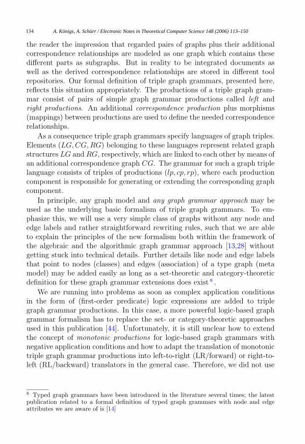
Figure 14 presents an example of a previously introduced TGG rule andshows the partition of this rule in its subcomponents.
When applied this rule creates the primary objects f and uc with the pro-vided values for their name attributes. For this purpose the triple graph mustcontain a FeatureGroup and a Package to which the primary objects will beattached to. Additionally, the FeatureGroup and the Package must alreadybe linked by a correspondence link of the type FeatureGroupPackageRelation.Finally, the value of the attribute name of f must equal the value of the at-tribute name of uc. This rule does not create any secondary objects.
3 Deriving operational rules
Model-integrating consistency rules are specified using the declarative TGGapproach and cannot be used directly for model integration purposes. Asalready mentioned above we translate declarative TGG rules into operationalgraph model transformation rules. These operational rules should cover thefollowing model/tool integration scenarios:
(i) Rules are needed which check whether an existing correspondence link be-tween two models is still valid or not. This includes checking whether thelocal contexts of connected elements still exists, whether the inter-model
name = x name = y
inter-documentrelationship
addFeatureAndUseCase( x : String, y : String)
local context local contextConstraint:
f.name = uc.name
<<new>><<new>>
<<new>><<new>>
<<new>>
:FeatureUseCaseRelation
<<new>>
uc:UseCase
<<new>>
f:Feature
:FeatureGroupPackageRelation :Package:FeatureGroup
A. Königs, A. Schürr / Electronic Notes in Theoretical Computer Science 148 (2006) 113–150 131

:FeatureGroup :FeatureGroupPackageRelation :Package
f:Feature uc:UseCase<<if>>
:FeatureUseCaseRelation
:FeatureGroup :Package:FeatureGroupPackageRelation
<<new>>
:FeatureUseCaseRelation
uc:UseCasef:Feature
:FeatureGroup :Package:FeatureGroupPackageRelation
<<new>>
:FeatureUseCaseRelation
<<new>>
uc:UseCase
f:Feature
:FeatureGroup :Package:FeatureGroupPackageRelation
<<new>>
:FeatureUseCaseRelation
uc:UseCase<<new>>
f:Feature
<<new>> <<new>>
<<new>> <<new>>
<<new>>
<<new>> <<new>>
<<new>>
Constraint:
f.name = uc.name
Constraint:
f.name = uc.name
uc.name := f.name f.name := uc.name
a) checkConsistency() b) createCorrespondenceLink()
c) doLRTransformation() d) doRLTransformation()
Fig. 15. Derived operational rules
relationships are fulfilled, and whether the attached attribute constraintstill holds.
(ii) Other rules should be available which create all possible consistency linksbetween matching elements of regarded model pairs.
(iii) Furthermore, there should be rules that propagate the creation of objectsfrom one model to the other combined with the automatic creation ofappropriate correspondence links.
(iv) Finally, we want to have a set of repair actions that can be applied whena consistency check fails. This includes a rule that propagates attributechanges from one element to the linked one if the constraint is violated inthe selected direction, a rule that removes an invalid correspondence link,and rules that propagate the deletion of linked objects from one modelto the other. These repair actions are not considered in this paper. Thereader is referred to [22] for more details.
It is the main advantage of triple graph grammars that they may auto-matically be translated into various sets of regular operational graph trans-formation rules which support all tool integration scenarios listed above. Thegeneral idea of this translation process is as follows: First of all the two re-garded models plus the correspondence links between them are considered tobe a single graph (with three distinct subgraphs). Then all TGG rules aretranslated into regular graph transformation rules which manipulate differentparts of the new graph as needed.
A. Königs, A. Schürr / Electronic Notes in Theoretical Computer Science 148 (2006) 113–150132
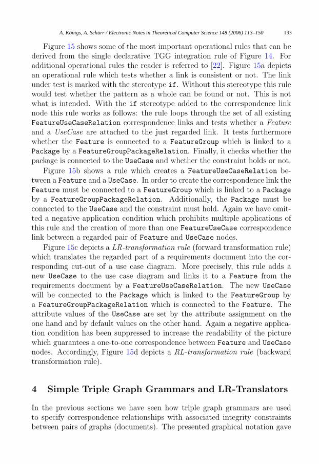
Figure 15 shows some of the most important operational rules that can bederived from the single declarative TGG integration rule of Figure 14. Foradditional operational rules the reader is referred to [22]. Figure 15a depictsan operational rule which tests whether a link is consistent or not. The linkunder test is marked with the stereotype if. Without this stereotype this rulewould test whether the pattern as a whole can be found or not. This is notwhat is intended. With the if stereotype added to the correspondence linknode this rule works as follows: the rule loops through the set of all existingFeatureUseCaseRelation correspondence links and tests whether a Featureand a UseCase are attached to the just regarded link. It tests furthermorewhether the Feature is connected to a FeatureGroup which is linked to aPackage by a FeatureGroupPackageRelation. Finally, it checks whether thepackage is connected to the UseCase and whether the constraint holds or not.
Figure 15b shows a rule which creates a FeatureUseCaseRelation be-tween a Feature and a UseCase. In order to create the correspondence link theFeature must be connected to a FeatureGroup which is linked to a Package
by a FeatureGroupPackageRelation. Additionally, the Package must beconnected to the UseCase and the constraint must hold. Again we have omit-ted a negative application condition which prohibits multiple applications ofthis rule and the creation of more than one FeatureUseCase correspondencelink between a regarded pair of Feature and UseCase nodes.
Figure 15c depicts a LR-transformation rule (forward transformation rule)which translates the regarded part of a requirements document into the cor-responding cut-out of a use case diagram. More precisely, this rule adds anew UseCase to the use case diagram and links it to a Feature from therequirements document by a FeatureUseCaseRelation. The new UseCase
will be connected to the Package which is linked to the FeatureGroup bya FeatureGroupPackageRelation which is connected to the Feature. Theattribute values of the UseCase are set by the attribute assignment on theone hand and by default values on the other hand. Again a negative applica-tion condition has been suppressed to increase the readability of the picturewhich guarantees a one-to-one correspondence between Feature and UseCase
nodes. Accordingly, Figure 15d depicts a RL-transformation rule (backwardtransformation rule).
4 Simple Triple Graph Grammars and LR-Translators
In the previous sections we have seen how triple graph grammars are usedto specify correspondence relationships with associated integrity constraintsbetween pairs of graphs (documents). The presented graphical notation gave
A. Königs, A. Schürr / Electronic Notes in Theoretical Computer Science 148 (2006) 113–150 133
the reader the impression that regarded pairs of graphs plus their additionalcorrespondence relationships are modeled as one graph which contains thesedifferent parts as subgraphs. But in reality to be integrated documents aswell as the derived correspondence relationships are stored in different toolrepositories. Our formal definition of triple graph grammars, presented here,reflects this situation appropriately. The productions of a triple graph gram-mar consist of pairs of simple graph grammar productions called left andright productions. An additional correspondence production plus morphisms(mappings) between productions are used to define the needed correspondencerelationships.
As a consequence triple graph grammars specify languages of graph triples.Elements (LG,CG, RG) belonging to these languages represent related graphstructures LG and RG, respectively, which are linked to each other by means ofan additional correspondence graph CG. The grammar for such a graph triplelanguage consists of triples of productions (lp, cp, rp), where each productioncomponent is responsible for generating or extending the corresponding graphcomponent.
In principle, any graph model and any graph grammar approach may beused as the underlying basic formalism of triple graph grammars. To em-phasize this, we will use a very simple class of graphs without any node andedge labels and rather straightforward rewriting rules, such that we are ableto explain the principles of the new formalism both within the framework ofthe algebraic and the algorithmic graph grammar approach [13,28] withoutgetting stuck into technical details. Further details like node and edge labelsthat point to nodes (classes) and edges (association) of a type graph (metamodel) may be added easily as long as a set-theoretic and category-theoreticdefinition for these graph grammar extensions does exist 8 .
We are running into problems as soon as complex application conditionsin the form of (first-order predicate) logic expressions are added to triplegraph grammar productions. In this case, a more powerful logic-based graphgrammar formalism has to replace the set- or category-theoretic approachesused in this publication [44]. Unfortunately, it is still unclear how to extendthe concept of monotonic productions for logic-based graph grammars withnegative application conditions and how to adapt the translation of monotonictriple graph grammar productions into left-to-right (LR/forward) or right-to-left (RL/backward) translators in the general case. Therefore, we did not use
8 Typed graph grammars have been introduced in the literature several times; the latestpublication related to a formal definition of typed graph grammars with node and edgeattributes we are aware of is [14]
A. Königs, A. Schürr / Electronic Notes in Theoretical Computer Science 148 (2006) 113–150134

Fig. 16. Application of Simple Productions and Triple Productions
any complex application conditions in the preceding sections except of simpleattribute equations 9 .
In the presented version of triple graph grammars the definition of a mono-tonic production is rather straight-forward. This means that any production’sleft-hand side must be part of its right-hand side, i.e. productions do notdelete vertices and edges. In this case, a given graph directly contains allnecessary information about its derivation history, and graph parsing simplymeans covering a given graph with right-hand sides of productions (for fur-ther details cf. [43]). This simplifies the development of LR- or RL-translatorsconsiderably which
• take a given left (right) graph as input and compute its derivation history,
• determine the related sequence of productions for the missing right (left)graph, and
• and apply the determined sequence of productions to generate the corre-sponding right (left) graph.
Requiring monotonicity is not as restrictive as it seems to be at a firstglance, since triple graph grammars are not intended to model editing pro-cesses on related graphs (with insertions as well as deletions and modificationsof graph elements), but are a generative description of graph languages andtheir relationships. Following this line, we start with the definition of simplegraphs, graph morphisms, and monotonic productions:
9 In this case node attributes may be encoded as pointers to auxilary nodes with uniquelabels as values; in this scenario testing the equality of two attributes simply means checkingwhether they are pointers to the same auxilary attribute node.
Remark:The sign “⊆” labels any arrow whichrepresents an inclusion.
⊆
g’
⊆
g PO
Diagram a) Diagram b)
G’
R
G
CL rh|CL
lg cg rg
lg’ cg’ rg’
lr rr
lr’ rr’
⊆⊆⊆
⊆⊆⊆
lh rh
L
RG’CG’
RG
LG’
CGLG
RRCR
RL
LR
CLLLlh|
A. Königs, A. Schürr / Electronic Notes in Theoretical Computer Science 148 (2006) 113–150 135
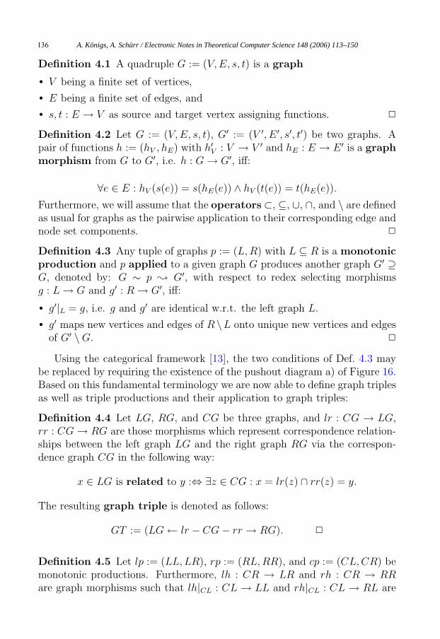
Definition 4.1 A quadruple G := (V, E, s, t) is a graph
• V being a finite set of vertices,
• E being a finite set of edges, and
• s, t : E → V as source and target vertex assigning functions. �
Definition 4.2 Let G := (V, E, s, t), G′ := (V ′, E ′, s′, t′) be two graphs. Apair of functions h := (hV , hE) with h′
V : V → V ′ and hE : E → E ′ is a graphmorphism from G to G′, i.e. h : G → G′, iff:
∀e ∈ E : hV (s(e)) = s(hE(e)) ∧ hV (t(e)) = t(hE(e)).
Furthermore, we will assume that the operators ⊂, ⊆, ∪, ∩, and \ are definedas usual for graphs as the pairwise application to their corresponding edge andnode set components. �
Definition 4.3 Any tuple of graphs p := (L, R) with L ⊆ R is a monotonicproduction and p applied to a given graph G produces another graph G′ ⊇G, denoted by: G ∼ p � G′, with respect to redex selecting morphismsg : L → G and g′ : R → G′, iff:
• g′|L = g, i.e. g and g′ are identical w.r.t. the left graph L.
• g′ maps new vertices and edges of R \L onto unique new vertices and edgesof G′ \ G. �
Using the categorical framework [13], the two conditions of Def. 4.3 maybe replaced by requiring the existence of the pushout diagram a) of Figure 16.Based on this fundamental terminology we are now able to define graph triplesas well as triple productions and their application to graph triples:
Definition 4.4 Let LG, RG, and CG be three graphs, and lr : CG → LG,rr : CG → RG are those morphisms which represent correspondence relation-ships between the left graph LG and the right graph RG via the correspon-dence graph CG in the following way:
x ∈ LG is related to y :⇔ ∃z ∈ CG : x = lr(z) ∩ rr(z) = y.
The resulting graph triple is denoted as follows:
GT := (LG ← lr − CG − rr → RG). �
Definition 4.5 Let lp := (LL, LR), rp := (RL,RR), and cp := (CL,CR) bemonotonic productions. Furthermore, lh : CR → LR and rh : CR → RRare graph morphisms such that lh|CL : CL → LL and rh|CL : CL → RL are
A. Königs, A. Schürr / Electronic Notes in Theoretical Computer Science 148 (2006) 113–150136
CL CR
CG CG’
⊆
cg’cg
⊆
RG’RG
RR
rh
PO
⊆rr
rr’
rg’
CL CR
CG CG’
⊆
cg’cg
⊆
LG’LG
LR
lh
PO
⊆lr
lr’
lg’
Fig. 17. Existence and Uniqueness of lr’ and rr
morphisms, too, which relate the left- and right- hand sides of productions lpand rp via cp to each other. The resulting triple production is:
p := (lp ← lh − cp − rh → rp).
And the application of such a triple production to a graph triple
GT := (LG ← lr − CG − rr → RG)
with redex selecting morphisms (lg, cg, rg) produces another graph triple
GT ′ := (LG′ ← lr′ − CG′ − rr′ → RG′),
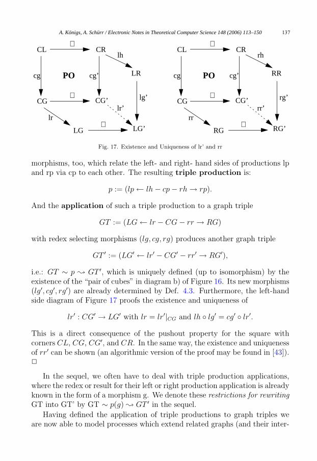
i.e.: GT ∼ p � GT ′, which is uniquely defined (up to isomorphism) by theexistence of the “pair of cubes” in diagram b) of Figure 16. Its new morphisms(lg′, cg′, rg′) are already determined by Def. 4.3. Furthermore, the left-handside diagram of Figure 17 proofs the existence and uniqueness of
lr′ : CG′ → LG′ with lr = lr′|CG and lh ◦ lg′ = cg′ ◦ lr′.
This is a direct consequence of the pushout property for the square withcorners CL, CG, CG′, and CR. In the same way, the existence and uniquenessof rr′ can be shown (an algorithmic version of the proof may be found in [43]).�
In the sequel, we often have to deal with triple production applications,where the redex or result for their left or right production application is alreadyknown in the form of a morphism g. We denote these restrictions for rewritingGT into GT’ by GT ∼ p(g) � GT ′ in the sequel.
Having defined the application of triple productions to graph triples weare now able to model processes which extend related graphs (and their inter-
A. Königs, A. Schürr / Electronic Notes in Theoretical Computer Science 148 (2006) 113–150 137
relationships) synchronously. But how can we handle the case, where a leftgraph is given and we have to construct the missing right graph including allinter-graph relationships or vice versa? For symmetry reasons, the solution isthe same in both directions. Therefore, the construction of LR-translators willbe discussed in detail and the solution for RL-translators may be obtained bysimply exchanging the roles of “left”- and “right”-hand side components.
Informally speaking we have to split a triple production p into a pair oftriple productions pL and pLR. pL is a left-local triple production which rewritesthe left graph only. pLR is a left-to-right translating triple production whichkeeps the new left graph unmodified but adjusts its correspondence and rightgraph. Within the following propositions we will show how to split a tripleproduction into a left-local production and a left-to-right transformation. Fur-thermore, we will prove that the application of a sequence of triple productionsis equivalent to the application of the corresponding sequence of left-local pro-ductions followed by the sequence of left-to-right transformations.
Theorem 4.6 A given triple production
p := ((LL, LR) ← lh − (CL,CR) − rh → (RL,RR))
may be split into the following pair of equivalent triple productions:
pL := ((LL, LR) ← ε − (�,�) − ε → (�,�))
is the left-local production for p, where � is the empty graph and ε is aninclusion of the empty graph � into any graph.
pLR := ((LR,LR) ← lh − (CL,CR) − rh → (RL,RR))
is the left-to-right translating production for p. For these triple produc-tions and any graph triples GT and GT ′ (as in Def. 4.5), and a morphismlg′ : LR → LG′ the following proposition holds:
GT ∼ p(lg′) � GT ′ ⇔ ∃HT : GT ∼ pL(lg′) � HT ∧ HT ∼ pLR(lg′) � GT ′.
Proof. The following equivalences prove that the vertical sides of the cubes ofFigure 16 b) and Figure 18 imply each other if all production applications use
A. Königs, A. Schürr / Electronic Notes in Theoretical Computer Science 148 (2006) 113–150138
the same morphism lg′ to select an image of graph LR in LG′ (and therebyof LL in LG):
LG ∼ (LL, LR) � LG′ ⇔ LG ∼ (LL, LR) � LG′ ∧ LG′ ∼ (LR,LR) � LG′.
CG ∼ (CL,CR) � CG′ ⇔ CG ∼ (CL,CL) � CG ∧ CG ∼ (CL,CR) � CG′
⇔ CG ∼ (�,�) � CG ∧ CG ∼ (CL,CR) � CG′.
RG ∼ (RL,RR) � RG′ ⇔ RG ∼ (RL,RL) � RG ∧ RG ∼ (RL,RR) � RG′
⇔ RG ∼ (�,�) � RG ∧ RG ∼ (RL,RR) � RG′.
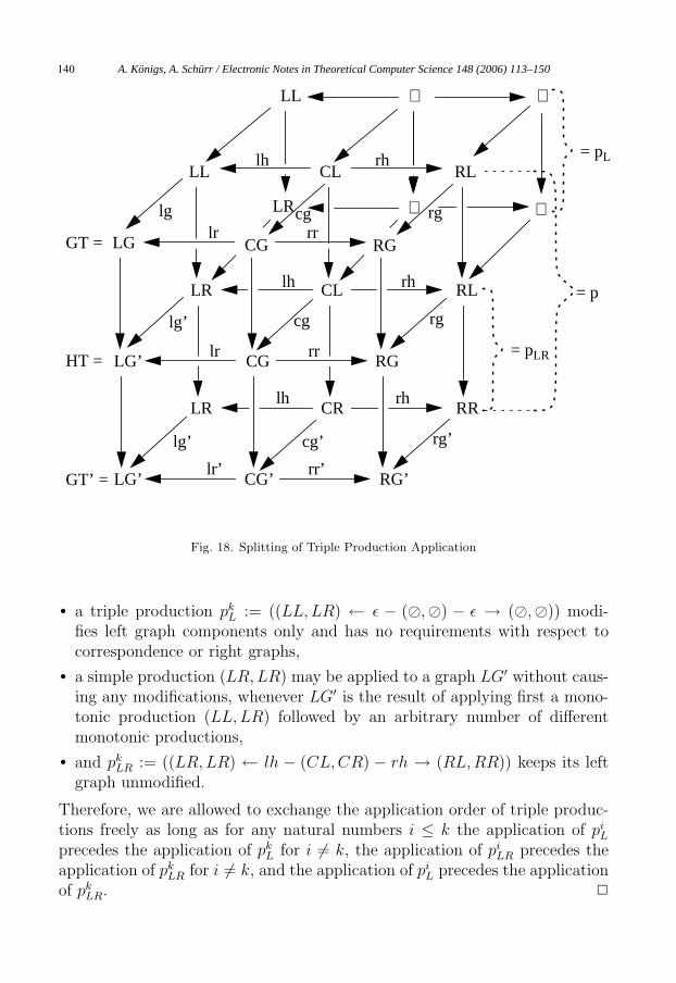
And Def. 4.5 guarantees existence and uniqueness of all horizontal arrows.Furthermore, diagram 16 b) is equivalent to GT ∼ p(lg′) � GT ′. We caneven merge the two rows of cubes in the upper part of the diagram of Fig. 18to a single row of cubes. Then, the new upper part of the diagram of Fig. 18is equivalent to GT ∼ pL(lg′) � HT . Finally, the lower part of the diagramof Fig. 18 is equivalent to HT ∼ pLR(lg′) � GT ′ . �
Please note that we used the name lr in Figure 18 to denote a morphismfrom CG to LG as well as its range extension to a morphism from CG toLG′ ⊇ LG. Furthermore, all arrows without any label denote inclusions andthe domain restrictions of lh and rh from CR to CL have been omitted inorder to keep the diagram as legible as possible.
In a similar way the splitting of a triple production into a right-local pro-duction followed by a right-to-left translating production may be defined, butwe have still to show that we can use these locally equivalent splittings for thedefinition of graph transformations which create first a left graph completelyand add a corresponding right graph and the accompanying correspondencegraph afterwards or vice versa, i.e. we have to prove:
Theorem 4.7 Given n triple productions p1 through pn and morphisms lg1
to lgn, which determine the application results of left production componentsof p1 through pn, we can prove that
p1(lg1) ◦ . . . ◦ pn(lgn) = (p1L(lg1) ◦ . . . ◦ pn
L(lgn)) ◦ (p1LR(lg1) ◦ . . . pn
LR(lgn)).
Proof. This follows directly from proposition 3.6 that ensures
p1(lg1) ◦ . . . ◦ pn(lgn) = (p1L(lg1) ◦ p1
LR(lg1)) ◦ . . . ◦ (pnL(lgn) ◦ pn
LR(lgn))
and the fact that
A. Königs, A. Schürr / Electronic Notes in Theoretical Computer Science 148 (2006) 113–150 139
LR CL RL
LR CR RR
LG’ CG RG
LG’ CG’ RG’
lh rh
lg’ cg rg
lg’ cg’ rg’
lr rr
lr’ rr’
lh rh
LL CL RL
LG CG RG
lg cglr rr
∅ ∅
∅ ∅
rg
lh rh
GT =
HT =
GT’ =
CG
LR
LL
= pL
= pLR
= p
Fig. 18. Splitting of Triple Production Application
• a triple production pkL := ((LL, LR) ← ε − (�,�) − ε → (�,�)) modi-
fies left graph components only and has no requirements with respect tocorrespondence or right graphs,
• a simple production (LR,LR) may be applied to a graph LG′ without caus-ing any modifications, whenever LG′ is the result of applying first a mono-tonic production (LL, LR) followed by an arbitrary number of differentmonotonic productions,
• and pkLR := ((LR,LR) ← lh − (CL,CR) − rh → (RL,RR)) keeps its left
graph unmodified.
Therefore, we are allowed to exchange the application order of triple produc-tions freely as long as for any natural numbers i ≤ k the application of pi
L
precedes the application of pkL for i �= k, the application of pi
LR precedes theapplication of pk
LR for i �= k, and the application of piL precedes the application
of pkLR. �
A. Königs, A. Schürr / Electronic Notes in Theoretical Computer Science 148 (2006) 113–150140

In a similar way, we can proof that a sequence of triple productions maybe replaced by an equivalent sequence of corresponding right-local and right-to-left translating productions. Therefore, the problem of constructing LR-or RL-translations is solved in principle. The realization of such a translationprocess is divided into two steps:
• The given source graph is analyzed and a sequence of left-local (right-local)productions is computed, which creates the given source graph (if possible).
• Afterwards, the corresponding sequence of LR-translating (RL-translating)productions is applied to the initial (empty) target graph.
For further details concerning the first step of this algorithm the reader isreferred to [43]. Furthermore, the topic of correspondence analysis is discussedon an informal level in [24]. An extension of the presented formalism of TGGsto n graphs (instead of pairs of graphs only) is out of the scope of this paperand discussed on an informal level in [22].
5 Related work
In this chapter we explain the relationships of our approach to the field ofmodel driven application development (MDA) [23] and OMG’s request for pro-posals (RFP) [32] for a MOF-compliant “queries, views, and transformation”(QVT) approach. Furthermore, we compare our proposal to those modeltransformation and integration approaches that address OMG’s QVT, too.For a detailed comparison of the TGG model integration approach in its orig-inal form with “classical tool/data integration approaches” developed in thelast millennium (like attribute-coupled grammars, broadcast message queryserver, etc.) the reader is referred to [29]. For a more comprehensive survey ofelder and rather recently developed tool integration techniques the reader isreferred to the CASE tool integration monography of Brown et al. [4] and thejust published special sections on tool integration issues of the two Springerjournals SoSym [45] and STTT [10].
5.1 OMG’s QVT-RFP
Although the field of data and tool integration has been studied for abouttwenty years now there still is a lack of domain-specific adaptable tool/dataintegration solutions which support consistency checking as well as incrementalupdate propagation and which are not restricted to one-way transformationsbetween pairs of tools only. This problem is addressed by OMG’s Request forproposals: MOF 2.0 Query/View/Transformation (QVT). This RFP demands
A. Königs, A. Schürr / Electronic Notes in Theoretical Computer Science 148 (2006) 113–150 141

a number of features which can be used for classifying data and tool integrationapproaches. Each response to the RFP must:
• offer a language for specifying queries for selecting and filtering of modelelements.
• provide a language for model transformation definitions. These definitionscan be used to generated a target model from a given source model.
• have a MOF 2.0-compliant abstract syntax for each language.
• have an expressive transformation language allowing automatic transforma-tions.
• support the creation of views.
• support incremental change propagation between source and target model.
Additionally, a response may:
• offer transformations which can be executed in both directions.
• provide traceability information.
• use generic transformation definitions for reuseability purposes.
• provide some sort of transactional mechanism.
• support the use of additional data which is not contained in the sourcemodel.
• allow transformations for the case that source and target model coincide.
For an extensive survey of model-transformation and integration approachesin general the reader is referred to [9]. This survey distinguishes among otherthings (e.g. features of transformation rules, features of rule application scop-ing, source-target relationship) between the following main categories of ap-proaches:
• declarative approaches usually offer a logic-based language for the definitionof consistency constraints between related models and are able to deriveconsistency checking and inconsistency removing update operations fromthese constraints.
• graph transformation approaches interpret models as graphs and use graphtransformation rules to describe one-way translations of one model intoanother one.
• hybrid approaches that combine diffrent techniques from the other cate-gories.
A. Königs, A. Schürr / Electronic Notes in Theoretical Computer Science 148 (2006) 113–150142

With respect to Czarnecki’s categorization of model transformation approaches,TGGs and MDI are hybrid approaches that combine the advantages of declar-ative and graph transformation approaches.
5.2 Related approaches
In the following, we will select some model transformation approaches whichare typical representatives of the above listed categories of Czarnecki andcompare them based on the list of requirements of OMG’s RFP QVT.
The submission from the QVT-partners [39] to OMG’s QVT-RFP aimsat model integration by means of so-called relations and mappings. The ap-proach is similar to our own in the way that it allows for model consistencychecking based on relation definitions, and doing forward and backward modeltransformations by defining mappings. One difference to our approach is thatthe model checking and model transformation rules are textually denoted 10 .Furthermore, the rules are not declarative. That means that the rules forforward and backward model transformations are not automatically derivedand must be specified manually. As a consequence there are no guaranteesthat consistency checking relations, forward and backward transformations fora pair of models implement the same set of constraints. Figure 19 gives animpression of how relation and mapping specifications look like. The relationfrom Figure 19a describes the correspondence between a method in a UMLclass diagram and an XML element which should represent this method. Therelation says that for each method in the UML class diagram there existsan XML element with the name Method. The XML element provides an at-tribute with the name name and a value n which corresponds to the nameof the method in the UML class diagram. Furthermore, the XML elementcontains the method’s body b. Accordingly, the mapping from Figure 19bdescribes in which way a XML element is created from a given method in aUML class diagram.
The goal of the graph transformation system GReAT [2] is to allow for theoperational specification of rather complex model transformations. As we do,this approach uses graph rewriting rules based on a UML-like notation. Incontrast to our own approach GReAT is not designed to keep existing modelsconsistent with each other. GReAT takes one model as input and completelytransforms it to another model. GReAT aims at a very expressive languagefor graph rewriting rules. Besides multiplicities for graph nodes the languageintroduces multiplicities for edges in graph rewriting rules for simultaneous
10 An additional graphical visualization has been defined, but its role for the definition ofmodel transformations is unclear
A. Königs, A. Schürr / Electronic Notes in Theoretical Computer Science 148 (2006) 113–150 143

relation Method_And_XML {
domain {
(UML.Method) [name = n, body = b]
}
domain {
(XML.Element) [name = "Method",
attributes = {
(XML.Attribute)
[name = "name", value = n]},
contents = {b}
]
}
}
mapping Method_To_XML
refines Method_And_XML {
domain {
(UML.Method) [name = n, body = b]
}
body {
(XML.Element) [name = "Method",
attributes = {
(XML.Attribute)
[name = "name", value = n]},
contents = {b}
]
}
}
a) b)
Fig. 19. Relation and mapping specifications in QVT-partners’ approach
TLR
FR
Sys
Block
Attribute
id:String
Attribute
name:String
in out
Guard
AttributeMapping
Fig. 20. Example rule specification in GReAT
manipulation of sets of rule matches. Additionally, it offers sophisticatedcontrol structures as sequences, non-determinism, hierarchical expressions, re-cursion, and branching. Figure 20 shows how rules in GReAT look like. Eachrule may provide in and out parameters for passing objects to the rules. Inthe example the object TLR acts as the in and out parameter. The patternof each rule is a graph rewriting rule. The ticks read like our new stereotypesand designate elements that are created during rule application. Addition-ally, each rule may provide a Guard that is checked before rule application.The Attribute Mapping expresses which values the attributes of the createdobjects get.
Like GReAT the BOTL approach [7] aims at model transformations. Sim-ilar to our approach it offers a UML-like notation for graph rewriting rulesworking on pairs of models/graphs. One difference is that this approach can-not be used for checking consistency of related models. BOTL just bidi-rectionally transforms one model to another model. Furthermore, it uses adifferent rule application strategy. Instead of applying one rule from of a setof concurrently applicable rules (selected by taking user preferences into ac-count), the BOTL approach applies all matching rules in parallel and merges
A. Königs, A. Schürr / Electronic Notes in Theoretical Computer Science 148 (2006) 113–150144

(Name):TLR
(Name):FR
(Name):Sys
(Name):BL
Fig. 21. Example rule specification in BOTL
<consistencyrule id="r1">
<description>
...
</description>
<forall var="a" in="/Adverts">
<exists var="p" in="/Catalogue/Products">
<equal op1="$a/ProductName/text()"
op2=„$p/Name/text()">
</exists>
</forall>
</consistencyrule>
Fig. 22. Example rule specification in xlinkit
the resulting set of graphs if possible. This is in our opinion a rather strangebehavior, at least in those cases, where different rules represent competingmodel transformation options and where rule-application conflicts should beresolved by a human being. An impression how rules in BOTL look like isgiven by Figure 21.
The xlinkit approach [27] is a typical example of a logic-based declarativeapproach. It is designed to detect inconsistencies on tools’ data represented byXML-files and to generate proposals how to remove existing inconsistenciesbetween pairs of models (manually). It uses a completely textual notationbased on first order logic and XML. Figure 22 demonstrates how a consistencychecking rule in xlinkit looks like. The rule states that for all elements inAdverts there must be an element in Catalogue/Products with the samename.
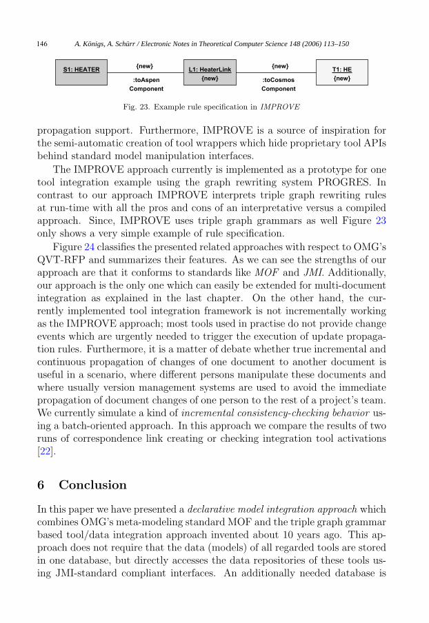
Finally, we should mention IMPROVE [8] which is also based on TGGsand has the same roots as our approach. It may be considered as a prede-cessor of the MDI approach presented here. It is mainly used for the incre-mental integration of pairs of tools in the field of chemical engineering andwas as far as we know the first TGG-based approach with a UML-like nota-tion. Unfortunately, it uses its own meta-modeling concepts inherited fromthe graph transformation system PROGRES [47] and is not compatible withOMG’s meta-modeling world. From IMPROVE we have learned how to deriveobject-deletion rules from a given TGG and how to offer incremental update
A. Königs, A. Schürr / Electronic Notes in Theoretical Computer Science 148 (2006) 113–150 145
L1: HeaterLink
{new}
S1: HEATER T1: HE
{new}
{new} {new}
:toAspen
Component
:toCosmos
Component
Fig. 23. Example rule specification in IMPROVE
propagation support. Furthermore, IMPROVE is a source of inspiration forthe semi-automatic creation of tool wrappers which hide proprietary tool APIsbehind standard model manipulation interfaces.
The IMPROVE approach currently is implemented as a prototype for onetool integration example using the graph rewriting system PROGRES. Incontrast to our approach IMPROVE interprets triple graph rewriting rulesat run-time with all the pros and cons of an interpretative versus a compiledapproach. Since, IMPROVE uses triple graph grammars as well Figure 23only shows a very simple example of rule specification.
Figure 24 classifies the presented related approaches with respect to OMG’sQVT-RFP and summarizes their features. As we can see the strengths of ourapproach are that it conforms to standards like MOF and JMI. Additionally,our approach is the only one which can easily be extended for multi-documentintegration as explained in the last chapter. On the other hand, the cur-rently implemented tool integration framework is not incrementally workingas the IMPROVE approach; most tools used in practise do not provide changeevents which are urgently needed to trigger the execution of update propaga-tion rules. Furthermore, it is a matter of debate whether true incremental andcontinuous propagation of changes of one document to another document isuseful in a scenario, where different persons manipulate these documents andwhere usually version management systems are used to avoid the immediatepropagation of document changes of one person to the rest of a project’s team.We currently simulate a kind of incremental consistency-checking behavior us-ing a batch-oriented approach. In this approach we compare the results of tworuns of correspondence link creating or checking integration tool activations[22].
6 Conclusion
In this paper we have presented a declarative model integration approach whichcombines OMG’s meta-modeling standard MOF and the triple graph grammarbased tool/data integration approach invented about 10 years ago. This ap-proach does not require that the data (models) of all regarded tools are storedin one database, but directly accesses the data repositories of these tools us-ing JMI-standard compliant interfaces. An additionally needed database is
A. Königs, A. Schürr / Electronic Notes in Theoretical Computer Science 148 (2006) 113–150146
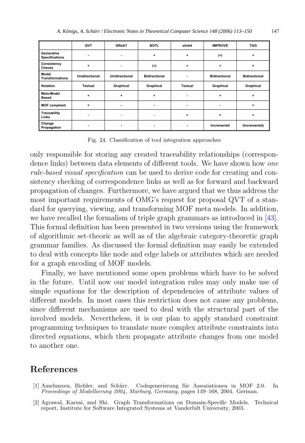
(Incremental)Incremental----Change
Propagation
+++---Traceability
Links
+----+MOF compliant
++-+++Meta-Model
Based
GraphicalGraphicalTextualGraphicalGraphicalTextualNotation
BidirectionalBidirectional-BidirectionalUnidirectionalUnidirectionalModel
Transformations
+++(+)-+Consistency
Checks
+(+)++--Declarative
Specifications
TGGIMPROVExlinkitBOTLGReATQVT
Fig. 24. Classification of tool integration approaches
only responsible for storing any created traceability relationships (correspon-dence links) between data elements of different tools. We have shown how onerule-based visual specification can be used to derive code for creating and con-sistency checking of correspondence links as well as for forward and backwardpropagation of changes. Furthermore, we have argued that we thus address themost important requirements of OMG’s request for proposal QVT of a stan-dard for querying, viewing, and transforming MOF meta models. In addition,we have recalled the formalism of triple graph grammars as introduced in [43].This formal definition has been presented in two versions using the frameworkof algorithmic set-theoric as well as of the algebraic category-theoretic graphgrammar families. As discussed the formal definition may easily be extendedto deal with concepts like node and edge labels or attributes which are neededfor a graph encoding of MOF models.
Finally, we have mentioned some open problems which have to be solvedin the future. Until now our model integration rules may only make use ofsimple equations for the description of dependencies of attribute values ofdifferent models. In most cases this restriction does not cause any problems,since different mechanisms are used to deal with the structural part of theinvolved models. Nevertheless, it is our plan to apply standard constraintprogramming techniques to translate more complex attribute constraints intodirected equations, which then propagate attribute changes from one modelto another one.
References
[1] Amelunxen, Bichler, and Schurr. Codegenerierung fur Assoziationen in MOF 2.0. InProceedings of Modellierung 2004, Marburg, Germany, pages 149–168, 2004. German.
[2] Agrawal, Karsai, and Shi. Graph Transformations on Domain-Specific Models. Technicalreport, Institute for Software Integrated Systems at Vanderbilt University, 2003.
A. Königs, A. Schürr / Electronic Notes in Theoretical Computer Science 148 (2006) 113–150 147
[3] Borras et al. Centaur: The System. In Henderson, editor, Proc. 3rd Symp., volume 5 of ACMSoftware Engineering Notes 13, pages 14–24, 1988.
[4] Brown et al. Principles of CASE Tool Integration. Oxford University Press, 1994.
[5] Bottoni et al. Working on OCL with Graph Transformations. In APPLIGRAPH Workshopon Applied Graph Transformation, pages 1–10, 2002. http://www.informatik.uni-bremen.de/-theorie/-AGT2002/-procAGT.pdf.gz.
[6] Borland. Together. http://www.borland.com/together.
[7] Braun. Metamodellbasierte Kopplung von Werkzeugen in der Softwareentwicklung. LogosVerlag, 2004. German, PhD thesis.
[8] Becker and Westfechtel. Incremental Integration Tools for Chemical Engineering: An IndustrialApplication of Triple Graph Grammars. In 29th Intl. Workshop Graph-Theoretic Concepts inComputer Science, volume 2880 of LNCS, pages 46–57, 2003.
[9] Czarnecki and Helsen. Classification Of Model Transformation Approaches. In 2nd OOPSLAWorkshop on Generative Techniques in the context of Model Driven Architecture, 2003. http://www.softmetaware.com/oopsla2003/czarnecki.pdf.
[10] Dorr and Schurr, editors. Special Section on Tool Integration Applications and Frameworks.Journal of Software Tools for Technology Transfer, 2004. Springer-Verlag. to appear.
[11] Ehrig, Engels, Kreowski, and Rozenberg, editors. Handbook of Graph Grammars andComputing by Graph Transformation, volume 1. World Scientific Publishing, 1997.
[12] Ehrig, Engels, Kreowski, and Rozenberg, editors. Handbook of Graph Grammars andComputing by Graph Transformation, volume 2. World Scientific Publishing, 1999.
[13] Ehrig. Introduction to the Algebraic Theory of Graph Grammars (a Survey). In Proc.Int. Workshop on Graph-Grammars and Their Application to Computer Science and Biology,volume 73 of LNCS, pages 1–69. Springer Verlag, 1979.
[14] Ehrig, Prange, and Taentzer. Fundamental Theory for Typed Attributed GraphTransformations. In Ehrig et al., editors, Graph Transformations, Proc. 2nd Int. Conference,ICGT 2004, volume 3256 of LNCS, pages 161–177. Springer Verlag, 2004.
[15] Frankel. The ToolTalk Service. Sun Microsystems Inc., 1991.
[16] Fromme. HP Encapsulator: Bridging the Generation Gap. In Hewlett-Packard Journal, pages59–68, 1990.
[17] Garlan. Views for Tools in Integrated Environments. PhD thesis, Computer ScienceDepartment at Carnegie Mellon University, 1988.
[18] Ganzinger and Giegerich. Attribute Coupled Grammars. In Proc. ACM SIGPLAN ’84 Symp.on Compiler Construction, volume 6 of ACM SIGPLAN Notices 17, pages 172–184, 1984.
[19] Habermann and Notkin. Gandalf: Software Development Environments. In Special Issue onProgramming Environments, volume 12 of TOSE 12, pages 1117–1127, 1986.
[20] Jahnke, Schafer, and Zundorf. A Design Environment for Migrating Relational toObject Oriented Database Systems. In Proc. of the International Conference on SoftwareMaintenance, pages 163–170. IEEE Computer Society Press, 1996.
[21] Kaiser, Kaplan, and Micallef. Multiuser, Distributed Language-Based Environments. In IEEESoftware 4, volume 6, 1987.
[22] Konigs and Schurr. MDI - a Rule-Based Multi-Document and Tool Integration Approach.Special Section on Model-based Tool Integration in Journal of Software&Systems Modeling,2004. submitted for publication.
[23] Kleppe, Warmer, and Bast. MDA Explained. Addison-Wesley, 2003.
A. Königs, A. Schürr / Electronic Notes in Theoretical Computer Science 148 (2006) 113–150148
[24] Lefering. Development of Incremental Integration Tools Using Formal Specifications. Technicalreport aib-94-2, Fachgruppe Informatik at RWTH Aachen, 1994.
[25] Lefering and Schurr. Specification of Integration Tools. In Nagl, editor, Building Tightly-Integrated Software Development Environments: The IPSEN approach, volume 1170 of LNCS,pages 440–456. Springer Verlag, 1996.
[26] Minas and Shklar. DiaGen: A generator for diagram editors providing direct manipulationand execution of diagrams. In Haarslev, editor, Proc. 11th IEEE International Symposium onVisual Languages, pages 203–210. IEEE Computer Society Press, 1995.
[27] Nentwich et al. xlinkit: A Consistency Checking and Smart Link Generation Service. In ACMTransactions on Internet Technology, volume 2, pages 151–185, 2002.
[28] Nagl. Graph-Grammatiken. Vieweg Press, 1979. German.
[29] Nagl, editor. Building Tightly Integrated Software Development Environments: The IPSENApproach, volume 1170 of LNCS. Springer Verlag, 1996.
[30] Nickel, Niere, and Zundorf. The FUJABA Environment. In Proc. of the 22nd InternationalConference on Software Engineering, pages 742–745, 2000.
[31] Nagl, Schurr, and Munch, editors. Proc. of 1st Intl. Workshop Applications of GraphTranformations with Industrial Relevance, volume 1779 of LNCS. Springer-Verlag, 1999.
[32] OMG. Request for Proposal: MOF 2.0 Query/Views/Transformations RFP, 2002. http://www.omg.org/cgi-bin/doc?ad/2002-04-10.
[33] OMG. MOF 2.0 Specification, 2003. http://www.omg.org/cgi-bin/-doc?ad/2003-04-07.
[34] OMG. OCL specification, 2003. http://www.omg.org/cgi-bin/doc?ad/2003-01-07.
[35] OMG. UML 2.0 superstructure specification, 2003. http://www.omg.org/cgi-bin/doc?ptc/2003-08-02.
[36] Pfaltz, Nagl, and Bohlen, editors. Proc. of 2nd Intl. Workshop Applications of GraphTranformations with Industrial Relevance, volume 3062 of LNCS. Springer-Verlag, 2003.
[37] Pfaltz and Rosenfeld. Web Grammars. In Int. Joint Conference on Artificial Intelligence,pages 609–619, 1969.
[38] Pratt. Pair Grammars, Graph Languages and String-to-Graph Translations. In Journal ofComputer and System Sciences, volume 5, pages 560–595. Academic Press, 1971.
[39] QVT-partners. QVT-partners revised submission to QVT, 2003. http://qvtp.org/downloads/1.1/qvtpartners1.1.pdf.
[40] Rensink. State Space Abstraction using Shape Graphs. In Automatic Verification of Infinite-State Systems (AVIS), Electronic Notes in Theoretical Computer Science. Elsevier, 2004. toappear.
[41] Rekers and Schurr. Defining and parsing visual languages with layered graph grammars.Journal of Visual Languages and Computing, 8(1):27–55, 1997.
[42] Schneider. Chomsky-Systeme fur partielle Ordnungen. Arbeitsbericht 3,3, Institut furMathematische Maschinen und Datenverarbeitung, Erlangen, 1970. German.
[43] Schurr. Specification of graph translators with triple graph grammars. In Mayr and Schmidt,editors, Proc. WG’94 Workshop on Graph-Theoretic Concepts in Computer Science, pages151–163, 1994.
[44] Schurr. Programmed Graph Replacement Systems. In Rozenberg, editor, Handbook of GraphGrammars and Computing by Graph Transformation, volume 1, chapter 7, pages 479–546.World Scientific Publishing, 1997.
[45] Schurr and Dorr, editors. Special Section on Model-based Tool Integration. Journal ofSoftware&Systems Modeling, 2004. Springer-Verlag. to appear.
A. Königs, A. Schürr / Electronic Notes in Theoretical Computer Science 148 (2006) 113–150 149

[46] Staudt, Krueger, and Garlan. A Structural Approach to the Maintenance of Structure-OrientedEnvironments. In Henderson, editor, Proc. 2nd Symp., volume 1 of ACM SIGPLAN Notices22, pages 160–170, 1987.
[47] Schurr, Winter, and Zundorf. The PROGRES Approach: Language and Environment.In Ehrig, Engels, Kreowski, and Rozenberg, editors, Handbook of Graph Grammars andComputing by Graph Transformation, volume 2, pages 487–550. World Scientific Publishing,1999.
[48] Taentzer. AGG: A Graph Transformation Environment for System Modeling and Validation.In Proc. Tool Exhibition at Formal Methods 2003, 2003.
[49] Telelogic. DOORS. http://www.telelogic.com/products/doorsers/doors.
[50] Varro. Automated Formal Verification of Visual Modeling Languages by Model Checking.Journal of Software and Systems Modelling, 2003. Springer-Verlag.
[51] Wagner. Realisierung eines diagrammubergreifenden Konsistenzmanagement-Systems furUML-Spezifikationen. Master’s thesis, Universitat Paderborn, 2001. German.
A. Königs, A. Schürr / Electronic Notes in Theoretical Computer Science 148 (2006) 113–150150