To my parents, Amanda Duarte and Alfonso...
124
1 COMPARISON OF WIND-DRIVEN RAIN TEST METHODS FOR RESIDENTIAL FENESTRATION By CARLOS R. LOPEZ A THESIS PRESENTED TO THE GRADUATE SCHOOL OF CIVIL ENGINEERING AT THE UNIVERSITY OF FLORIDA IN PARTIAL FULFILLMENT OF THE REQUIREMENTS FOR THE DEGREE OF MASTER OF ENGINEERING UNIVERSITY OF FLORIDA 2009
Transcript of To my parents, Amanda Duarte and Alfonso...

1
COMPARISON OF WIND-DRIVEN RAIN TEST METHODS FOR RESIDENTIAL FENESTRATION
By
CARLOS R. LOPEZ
A THESIS PRESENTED TO THE GRADUATE SCHOOL OF CIVIL ENGINEERING AT THE UNIVERSITY OF FLORIDA IN PARTIAL
FULFILLMENT OF THE REQUIREMENTS FOR THE DEGREE OF MASTER OF ENGINEERING
UNIVERSITY OF FLORIDA
2009

2
© 2009 Carlos R. Lopez

3
To my parents, Amanda Duarte and Alfonso Lopez

4
ACKNOWLEDGMENTS
Without the help of the oversight committee this research project would not have been
possible. I would like to thank: Alside, American Architectural Manufacturers Association
(AAMA), American Forest & Paper Association (AFPA), APA–The Engineered Wood
Association, Architectural Testing Inc., Atrium Companies Inc., Cast-Crete Corporation, C.B.
Goldsmith and Associates Inc., CEMEX, Certified Test Labs, Do Kim & Associates, DuPont,
Fenestration Manufacturers Association (FMA), Florida Building Commission, Florida Home
Builders Association (FHBA), General Aluminum, Henkel, Institute for Business and Home
Safety (IBHS), James Hardie, JBD Code Services, JELD-WEN Windows and Doors, Lawson
Industries Inc., Marvin Windows and Doors, Masonry Information Technologists Inc., MI
Windows and Doors, NuAir Windows and Doors, Painter Masonry Inc., PGT Industries, PPG
Industries, Protecto Wrap Company, Silver Line Windows and Doors, Simonton Windows,
TRACO, and WCI Group Inc.
I would also like to thank my faculty advisor, Forrest J. Masters, Ph.D., and committee
members Kurtis R. Gurley, Ph.D. and David O. Prevatt, Ph.D., P.E. for their advice and
guidance.
This research was supported by the National Science Foundation (CMMI- 0729739) and
the State of Florida Department of Community Affairs.

5
TABLE OF CONTENTS Page
ACKNOWLEDGMENTS ...............................................................................................................4
LIST OF FIGURES .........................................................................................................................8
ABSTRACT ...................................................................................................................................11
CHAPTER
1 INTRODUCTION ..................................................................................................................13
Recent Hurricane Impacts .......................................................................................................14 Water Penetration Resistance Requirements for Residential Fenestration .............................16 Scope of Research ...................................................................................................................17
2 WIND-DRIVEN RAIN INGRESS THROUGH THE BUILDING ENVELOPE .................23
Rainfall Intensity ....................................................................................................................23 Raindrop Size Distribution .....................................................................................................24 Rainfall Trajectory ..................................................................................................................25 Wetting of the Building Façade ..............................................................................................26 Water Ingress through the Building Façade ...........................................................................28 Summary .................................................................................................................................30
3 WATER PENETRATION RESISTANCE TEST METHODS .............................................32
Uniform Static Air Pressure Difference .................................................................................32 Cyclic Static and Cyclic Air Pressure Difference ...................................................................33 Pseudo-Dynamic Pressure ......................................................................................................35 Summary .................................................................................................................................36
4 EXPERIMENTAL PROCEDURE .........................................................................................42
Testing Apparatuses ................................................................................................................42 Negative (Suction) Air Pressure Chamber ......................................................................42 Positive (Stagnation) Air Pressure Chamber ...................................................................43 Hurricane Simulator ........................................................................................................44 Full Scale House Mockup ...............................................................................................45 Air Caster Cart .................................................................................................................46
Testing Protocols and Sequencing ..........................................................................................46 Static Air Pressure Difference .........................................................................................47 Cyclic Static Air Pressure Difference ..............................................................................48 Dynamic Pressure ............................................................................................................48 Water Infiltration Rates ...................................................................................................49
Summary .................................................................................................................................51

6
5 SPECIMEN DESIGN AND CONSTRUCTION ...................................................................68
Wood Frame Wall Specimens ................................................................................................68 Masonry Wall Specimens .......................................................................................................69 Testing Matrix ........................................................................................................................70 Summary .................................................................................................................................70
6 RESULTS ...............................................................................................................................79
Assessment of Repeatability during the Test Series ...............................................................79 Comparison of Results from Static, Cyclic and Dynamic Test Methods ...............................81 Intercomparison of Window Operator Water Penetration Resistance ....................................82
Operable Window Infiltration Rate Testing ....................................................................83 Summary .................................................................................................................................85
7 KEY FINDINGS ..................................................................................................................100
Comparison of Test Methods ...............................................................................................100 Performance of Window Assemblies ...................................................................................101
APPENDIX A: SPECIMEN RECORDS.....................................................................................103
LIST OF REFERENCES .............................................................................................................119
BIOGRAPHICAL SKETCH .......................................................................................................123

7
LIST OF TABLES Table page 1-1 Ten Costliest Mainland United States Tropical Cyclones, 1900-2006 ...................................19
1-2 Saffir Simpson Scale ..............................................................................................................19
3-1 Draft AAMA 520 Performance Levels ...................................................................................37
3-2 Summary of Existing Testing Protocols ..................................................................................37
4-1 Pressure Series for Cyclic Pressure Test Method ....................................................................52
5-1 Test Specimen Matrix ..............................................................................................................71
5-2 Test Specimen Matrix ..............................................................................................................72
6-1 Time to Leakage and Corresponding Pressure in Uniform Static Pressure Tests ...................87
6-2 Number of Leakage Paths Observed in Uniform Static Pressure Tests ..................................88
6-3 Leakage Paths Observed in Static, Cyclic and Dynamic Tests ...............................................89
6-4 Leakage Path Detection Comparison ......................................................................................90
6-5 Evaluation of Operable Windows With Respect to Pressure of First Leakage Path ...............91
6-6 Average Percentage of Design Pressure for Which Leakage Occurred ..................................91

8
LIST OF FIGURES
Figure page 1-1 Percent of Natural Disasters over 1.0 Billion Dollars ............................................................20
1-2 Allocation of Insured Losses since 1984 ................................................................................20
1-3 Normalized Losses since 1980 ...............................................................................................21
1-4 Paths of 10 Costliest United States Tropical Cyclones ..........................................................21
1-5 Florida Impacting Hurricanes of 2004 ....................................................................................22
1-6 Hurricane Activity of 2004 and 2005 Seasons .......................................................................22
2-1 Components of the Rain Intensity Vector ...............................................................................31
2-2 Typical Drop Size Shapes .......................................................................................................31
3-1 ASTM E331-00 Pressure Loading History ............................................................................39
3-2 TAS 202-94 Pressure Loading History ..................................................................................39
3-3 ASTM E2268-04 Pressure Loading History ..........................................................................40
3-4 ASTM 1105-00 Procedure B Pressure Loading History ........................................................40
3-5 ASTM E547-00 Pressure Loading History ............................................................................41
3-6 Draft AAMA 520 Pressure Loading History ..........................................................................41
4-1 Negative Pressure Chamber.....................................................................................................54
4-2 Electro-Pneumatic Valves .......................................................................................................55
4-3 Calibration Catch Box .............................................................................................................55
4-4 Posivie Pressure Chamber. ......................................................................................................57
4-5 Direct Drive Hydraulic Motor .................................................................................................58
4-6 Van-Axial Fan .........................................................................................................................58
4-7 Nozzle ......................................................................................................................................59
4-8 Hurricane Simulator. ...............................................................................................................60
4-9 Hydraulic Lift ..........................................................................................................................61
9
4-10 Roof to Wall Connection .......................................................................................................62
4-11 Air Caster Cart .......................................................................................................................62
4-12 Static Pressure Load Sequence ..............................................................................................63
4-13 Cyclic Pressure Load Sequence .............................................................................................63
4-14 Pressure Time History for Dynamic Test ..............................................................................64
4-15 Loading Functions for Specimen 017C .................................................................................65
4-16 Flow Data for Increasing Load Curve ...................................................................................66
4-17 Last 25% of Data for All Pressure Steps ...............................................................................66
4-18 Filtered Weight Data (1149 Pa/ 24 psf) Step of Specimen ....................................................67
5-1 Bolted Channels to Wood Frame Walls. .................................................................................73
5-2 Designs for Wood Frame Walls. .............................................................................................74
5-3 CMU Wall Specimen Stabilization Channel ...........................................................................75
5-4 Designs for CMU Wall ............................................................................................................76
5-5 Awning Window......................................................................................................................77
5-6 Casement Window ...................................................................................................................77
5-7 Single Hung Window ..............................................................................................................78
5-8 Horizontal Sliding Window .....................................................................................................78
6-1 Load and Unload Curves for Operable Windows Under Negative Load ................................93
6-2 Load and Unload Curves for Operable Windows Under Positive Load. ...............................95
6-3 Water Infiltrated at the End of Static Pressure Test ...............................................................96
6-4 Comparison of Performance of Operable Window Assemblies ..............................................97
6-5 Typical Infiltration for Casement Windows ............................................................................98
6-6 Typical Infiltration for Single Hung Windows ........................................................................98
6-7 Typical Infiltration for Single Hung Windows ........................................................................99
6-8 Typical Infiltration for Horizontal Sliding Windows ..............................................................99

10
7-1 Infiltration Paths Through the Right Side of the Operable Sill of Specimen #032. ..............102
A1-1 Specimen 001 Records .......................................................................................................103
A1-2 Specimen 006 Records .......................................................................................................104
A1-3 Specimen 011 Records .......................................................................................................105
A1-4 Specimen 019D Records .....................................................................................................106
A1-5 Specimen 020B Records .....................................................................................................107
A1-6 Specimen 022 Records .......................................................................................................108
A1-7 Specimen 025 Records .......................................................................................................109
A1-8 Specimen 032 Records .......................................................................................................110
A1-9 Specimen 043 Records .......................................................................................................111
A1-10 Specimen 048 Records .....................................................................................................112
A1-11 Specimen 049 Records .....................................................................................................113
A1-12 Specimen 054 Records .....................................................................................................114
A1-13 Specimen 064 Records .....................................................................................................115
A1-14 Specimen 067 Records .....................................................................................................116
A1-15 Specimen 070 Records .....................................................................................................117
A1-16 Specimen 073 Records .....................................................................................................118

11
Abstract of Thesis Presented to the Graduate School of Civil Engineering at the University of Florida in Partial Fulfillment of the
Requirements for the Degree of Master of Engineering
COMPARISON OF WIND-DRIVEN RAIN TEST METHODS FOR RESIDENTIAL FENESTRATION
By
Carlos R. Lopez
December 2009 Chair: Forrest J. Masters Cochair: Kurtis R. Gurley Major: Civil Engineering
While recent changes in building codes have resulted in better structural performance
during tropical cyclones, water intrusion through the building envelope continues to be a
recurring issue. As a result, industry and code officials have voiced a need to reevaluate the
standardized test methods in place for product approval.
Under the oversight of a task force that includes representatives from product
manufacturing, homebuilding, architecture, engineering, insurance, code development and test
laboratories, these methods have been investigated through a series of tests that examines full
scale wall/window specimens subjected to simulated wind driven rain (WDR) scenarios. These
WDR events were simulated using a pressure chamber, in which full-scale residential wall
systems were subjected to uniform, linearly varying, and cyclic pressure loads while the façade
was wetted. The specimens were also subjected to dynamic loads using a new turbulent wind
load simulation apparatus developed at the University of Florida (UF). It was discovered that the
static and cyclic pressure testing procedures used in the experiment described herein replicated
the results observed in the dynamic pressure test reasonably well. Holistic testing of the

12
specimens also yielded results that demonstrate the importance of testing products as an
assembly rather than in isolation.

13
CHAPTER 1 INTRODUCTION
Since 1980, ninety natural hazard events have cost the U.S. more than one billion dollars
individually [1]. The most costly of these events are tropical cyclones (see figure 1.1, data from
[1]). One-third of these hurricanes have caused an excess of one billion dollars in damages
They are more destructive than tornadoes, snow storms, and terrorism combined, accounting for
47.5% of insured losses since 1984 (figure 1-2, data from [6] and [7]) and amounting to
approximately $1.09 trillion dollars of damage since 1900 [3].
Florida, which is the most hurricane prone state in the U.S., is affected by 40% of all U.S.
landfalling hurricanes. Two of the three Saffir Simpson Hurricane Scale (SSHS) Category 5
storms on record have made landfall in Florida, and 39% of major storms have affected this state
[4]. Of the 10 most costly hurricanes impacting the U.S., eight made landfall in Florida (see
table 1.1) [4]. Between 1987 and 2006, $138 billion in insurance claims were paid to policy
holders [6, 7].
Florida’s susceptibility to hurricanes is also a function of its population density, which has
grown 85% (approximately $9.7 to 18.3 million) from 1980 to 2008, and expected to further
grow from 18.3 million current residents to 28.7 million residents in 2030 [5a]. The implications
of such a rapid increase in population is represented by the possibility of the next Category 5
storm yielding damages exceeding $80 billion dollars [6, 7] if it strikes a major population
center.
Preventative measures must be taken in order to lessen the effect of tropical cyclones on
residential structures. Thus, industry and code officials have voiced a need to reevaluate the
standardized test methods in place for the product approval of fenestration products. The
research herein addresses the mitigation of water ingress through wall systems with integrated

14
fenestration. It focuses on the water penetration resistance test methods used in the product
approval process for building codes in hurricane-prone areas. This chapter presents a brief
historical perspective on recent hurricane impacts, discusses water ingress through fenestration,
and provides an overview of the scope of work for this research.
Recent Hurricane Impacts
On August 24, 1992, Hurricane Andrew struck southeast Florida with sustained wind
speeds of 64.72 m/s (145 mph) and set the record as the most costly catastrophe of the 20th
century. It caused $26.5 billion in damage and is second only to hurricane Katrina, which was
responsible for $81.0 billion in damage [4]. The damage of Hurricane Andrew was quantified in
a report commissioned by then Florida Governor Lawton Chiles as (Executive order 92-291,
1992):
• 135,446 homes damaged or destroyed • 82,000 businesses damaged or destroyed • 7,800 businesses closed • 86,00 people unemployed
The devastation brought on by Hurricane Andrew raised many questions about building
performance. Many government agencies subsequently began to investigate the effectiveness of
the building codes and code compliance. The Federal Emergency Management Agency (FEMA)
assembled a team to survey the failures and found problems with inadequate designs, poor
workmanship, misapplication of building materials, improper review of construction permit
documents, shortages of inspection staff, as well as deficient training of inspecting staff [9].
These findings led to changes that intended to improve the wind resistance of new buildings in
Florida, including a tripling of the number of roofing inspectors in Dade County [6, 7]. New
standards were also implemented in the building code, such as the incorporation of window and
15
door standards that mandate the use of hurricane shutters or impact resistant glass, as well as a
mandatory review of plans by certified engineers [6, 7].
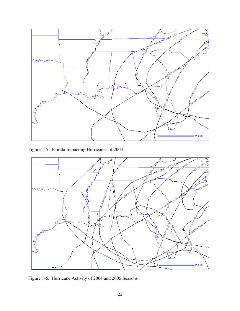
With the exception of Hurricane Opal (1995), Florida went without a notable landfall
during the next 10 years. In 2004 a record 27 disaster proclamations were issued for hurricanes
[10]. Florida was affected most severely, experiencing Hurricanes Charlie, Frances, Ivan, and
Jeanne [10]. The damage in parts of Florida was magnified by the concurrence of both time and
location of Charley, Frances and Jeanne (see figure 1-4). Jeanne and Frances followed almost
identical paths and overlapped regions of Florida already affected by Hurricane Charley. The
three storms were separated by 28 days (Landfalls: Charley August 13th, Frances September 5th,
and Jeanne September 25th [11]).
The most active season in recorded history occurred the following year. The 2005
hurricane season was one that exceeded many previous records [4]. Tropical storms formed
beyond the end of the Atlantic hurricane season as far as January 2006 (Zeta: Dec 30th to Jan 6th
[11]). Seven major hurricanes and a record four hurricanes reached Category 5 strength on the
Saffir-Simpson scale (Emily, Katrina, Rita, and Wilma [11]). Hurricane Katrina holds the record
for costliest disaster at $81.0 billion dollars [4]. Together the 2004 and 2005 produced 7 of the 9
costliest hurricanes to occur in the U.S. These seasons had a combined 43 named storms, 15 of
which made landfall on the United States costing an estimated $142 billion dollars in damage.
FEMA Mitigation Assessment Teams were tasked to investigate building performance and
found that main wind force resisting systems designed to post-Andrew building codes were
effective in withstanding extreme wind loads [10]. However, extensive damage occurred to
component and cladding systems, particularly through water ingress. In report FEMA 490, the
majority of building damage was attributed to “insufficient wind resistance of building envelope

16
systems which allowed wind-driven water infiltration into buildings, resulting in contents
damage and loss of function.” Furthermore, the authors stated that “the performance of building
envelope systems in high wind events requires attention. Design guidance and code changes are
needed.” This research specifically addresses this concern with regard to performance of the
window-wall systems, i.e., the window, wall, and interface (defined by the installation
technique).
Water Penetration Resistance Requirements for Residential Fenestration
There are many field and laboratory test methods that evaluate the water penetration
resistance of fenestration. These include static pressure tests (e.g., TAS 202-94 [47], ASTM
E331-00 [41], Procedure A of ASTM E1105-05 [43], and ASTM E547-00 [42]), cyclic static
pressure tests (e.g., TAS 203-94 [48], JIS A 1517 [46],and Procedure B of ASTM E1105-05
[43]), cyclic pressure tests (e.g. ASTM E2268-04 [44]), and dynamic tests (e.g., AAMA 501.1-
05 [39]). These tests stipulate a performance criterion, such as a maximum allowable
accumulation of water that overflows the innermost plane of the product. Most standards
stipulate that the corresponding load condition be equal to 15% of the structural design pressure
(AAMA/WDMA/CSA 101/I.S.2/A440 [38], TAS 202-94 [47]).
The principal question in this research is whether these conditions and the experimental
design are representative of hurricane conditions. Moreover, since windows are currently tested
in isolation, how do they perform when they are integrated into a finished wall system that might
propagate leaks into the cavity between the window and the rough opening of the wall? The
literature is scarce on the subject of holistic testing (i.e. testing of construction assemblies rather
than products in isolation) which is highly problematic considering the wide variety of window
options, installation methods, and finished wall systems available today. A thorough
understanding of the interaction of these products is essential due to the increasing number

17
products available. Consider that the numbers of new windows produced each year has
increased from 2 per 100 people in 1900 to 11.1 in 2000 [13].
Scope of Research
The objectives of this study are as follows:
• Develop a testing procedure that holistically evaluates the performance of the building system, i.e. a finished wall with an integrated window
• Evaluate existing fenestration testing protocols by analyzing these results with those attained from the full scale Hurricane Simulator at the University of Florida (See Masters et al. [49] , and Testing Apparatuses in Chapter 4).
• Examine the differences in water penetration behavior given various operable window assemblies.
To carry out this research, modified water penetration test methods were conducted on
sixteen full size wall specimens that varied in window size, window material, operator type, wall
construction, exterior finish, and sill type were constructed for evaluation. Each specimen
underwent four individual rounds of testing using static, cyclic, dynamic, and static load
sequences. The static and cyclic pressure tests were based on existing test methods. Water
penetration was quantified and compared with results from testing using the Hurricane Simulator
(detailed in Chapter 6). Testing using the Hurricane Simulator is used as the basis for
comparison, given that the wind loading is calibrated to data collected in the field by the Florida
Coastal Monitoring Program (FCMP) since 1999. The specimens were then subjected to a
second static pressure test (using the exact pressure loading and wetting as the first static test), to
determine if damage occurred during the first three tests. Specimens were loaded with both
positive and negative pressure to compare their relative results. Finally, results from these tests
were used to quantify the difference in water penetration resistance between different operator
types.

18
Chapter 2 reviews the literature on the topic of wind-driven rain ingress through residential
windows. An overview of existing water penetration resistance test methods is given in Chapter
3. Chapter 4 summarizes the experimental procedure. Specimen design and construction is
explained in Chapter 5. Results of the research project are discussed in Chapter 6. Chapter 7
contains conclusions and suggestions for new test methods and future research.

19
Table 1-1. Ten Costliest Mainland United States Tropical Cyclones, 1900-2006 Rank Hurricane Impact Year Internal Pressure Category Damage mbar USD 2006 USD 1 Katrina FL, LA 2005 920 3 81.0B 85.1B 2 Andrew FL, LA 1992 922 5 26.5B 58.6B 3 Wilma FL 2005 950 3 20.6B 21.6B 4 Charley FL 2004 941 4 15.0B 17.1B 5 Ivan FL,AL 2004 946 3 14.2B 16.2B 6 Hugo SC 1989 934 4 7.0B 16.0B 7 Agnes Fl 1972 980 1 2.1B 18.1B 8 Betsy Fl, LA 1965 948 3 1.4B 18.7B 9 Rita LA,TX 2005 937 3 11.3B 11.9B 10 Frances FL 2004 960 2 8.9B 10.2B Table 3a and table 3b from NWS TPC-5 [4] Table 1-2. Saffir Simpson Scale Category Winds Central Pressure Surge Damage m/s mph mbar in Hg m ft 1 33.1-42.5 74-95 >979 >28.9 1.2-1.8 4-6 Minimal 2 42.9-49.2 96-110 965-979 28.5-28.9 1.8-2.4 6-8 Moderate 3 49.6-58.1 111-130 945-964 27.9-28.5 2.4-3.7 9-12 Extensive 4 58.6-69.3 131-155 920-944 27.2-27.9 3.7-5.5 13-18 Extreme 5 69.3 >155 <920 <27.2 >5.5 >18 Catastrophic Table 3a from NWS TPC-5 [4]

20
Figure 1-1. Percent of Natural Disasters Over 1.0 Billion Dollars
Figure 1-2. Allocation of Insured Losses Since 1984

21
Figure 1-3. Normalized Losses Since 1980
Figure 1-4. Paths of 10 Costliest United States Tropical Cyclones
22
Figure 1-5. Florida Impacting Hurricanes of 2004
Figure 1-6. Hurricane Activity of 2004 and 2005 Seasons

23
CHAPTER 2 WIND-DRIVEN RAIN INGRESS THROUGH THE BUILDING ENVELOPE
Wind driven rain has been an active research topic for over a century [19]. In the area of
building science, research of the effects of wind driven rain on building components has
remained a difficult task for scientists. This is mainly due to the rapid progress of new and
innovative construction materials and practices. This imbalance has directly led to the inability
of building assemblies to withstand WDR loading, yielding water ingress. To explain this
phenomenon, this chapter will discuss the major factors of WDR leading to water ingress
through the building façade.
Rainfall Intensity
Extreme wind-driven rain events begin with the occurrence of rainfall accompanying wind
events. Rainfall rates as well as drop size distributions can vary throughout the duration of a
storm as well as from storm to storm [37]. Rainfall intensity (referred to in different literature as
unobstructed rainfall intensity) is defined as the depth of rainfall accumulated per unit of time.
Extreme short duration rainfall rates can reach 1872.0 mm/hr (73.7 in/hr, for one minute in
Maryland, 1956) and 432.0 mm/hr (17.0 in/hr for 42 min in Missouri, 1947) [37]; however,
statistical design rainfall rates are better representations. Technical Paper 40 from the National
Weather Service prescribes a maximum of 127.0 mm/hr (5.0 in/hr) for a 100 year return 60 min
rain event while most common test standards refer to a prescribed wetting of 203.0 mm/hr (8.0
in/hr, e.g. ASTM E331-00 [41], ASTM E1105-00, ASTM E2268-04 [44], and ASTM E547-00
[42]). This is the application required to cause water to sheet over a curtain wall, and is the
rainfall intensity used in this experiment. There also exists a higher specified rainfall intensity of
274.0 mm/hr (10.8 in/hr, 100 year return 5 min rain event [35]). These design scenarios seem to
well encompass rainfall in the northern hemisphere which rarely exceeds 144.0 mm/h (5.7 in/hr)
24
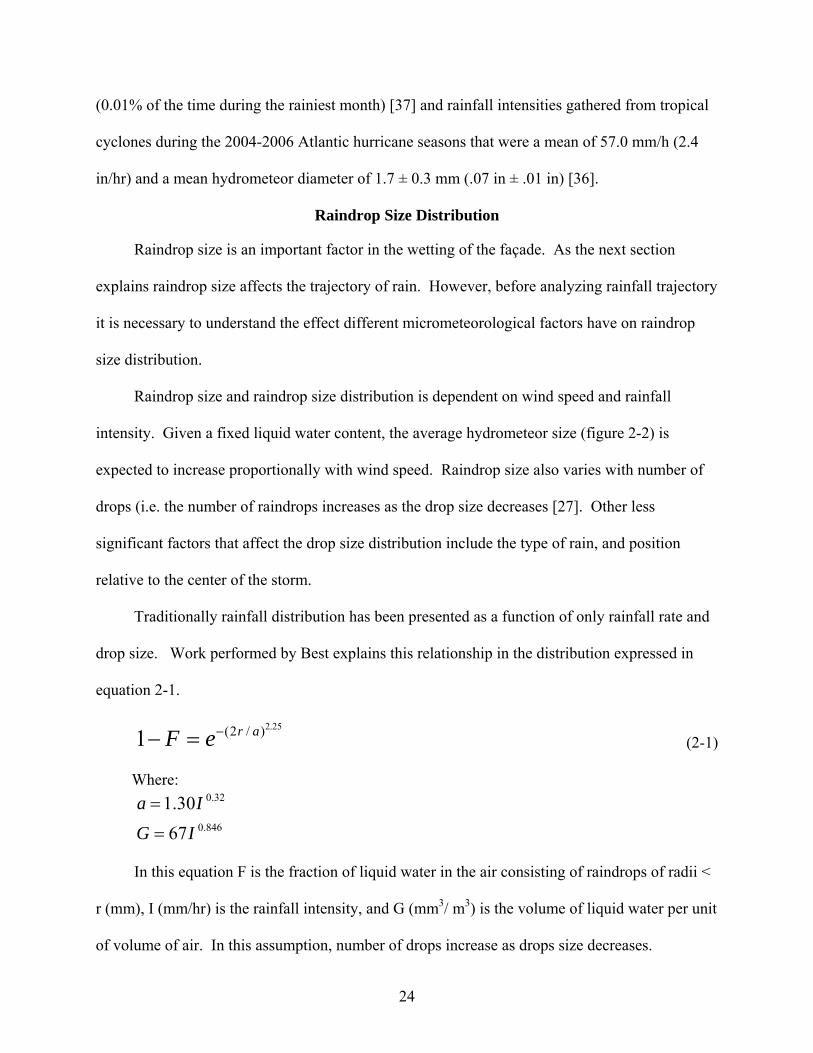
(0.01% of the time during the rainiest month) [37] and rainfall intensities gathered from tropical
cyclones during the 2004-2006 Atlantic hurricane seasons that were a mean of 57.0 mm/h (2.4
in/hr) and a mean hydrometeor diameter of 1.7 ± 0.3 mm (.07 in ± .01 in) [36].
Raindrop Size Distribution
Raindrop size is an important factor in the wetting of the façade. As the next section
explains raindrop size affects the trajectory of rain. However, before analyzing rainfall trajectory
it is necessary to understand the effect different micrometeorological factors have on raindrop
size distribution.
Raindrop size and raindrop size distribution is dependent on wind speed and rainfall
intensity. Given a fixed liquid water content, the average hydrometeor size (figure 2-2) is
expected to increase proportionally with wind speed. Raindrop size also varies with number of
drops (i.e. the number of raindrops increases as the drop size decreases [27]. Other less
significant factors that affect the drop size distribution include the type of rain, and position
relative to the center of the storm.
Traditionally rainfall distribution has been presented as a function of only rainfall rate and
drop size. Work performed by Best explains this relationship in the distribution expressed in
equation 2-1.
25.2)/2(1 areF −=− (2-1)
Where:
846.0
32.0
6730.1
IGIa
=
=
In this equation F is the fraction of liquid water in the air consisting of raindrops of radii <
r (mm), I (mm/hr) is the rainfall intensity, and G (mm3/ m3) is the volume of liquid water per unit
of volume of air. In this assumption, number of drops increase as drops size decreases.

25
Another rainfall intensity dependant distribution is the modified Γ-distribution (Equation
2-2) where N(D) is the concentration of drops having diameter D, NG is the concentration
parameter, Λ is the slope parameter, α is the curvature parameter, and D0 is the median volume
diameter [37].
DG eDNDN Λ−= α)( (2-2)
Where:
160.2
040
6
0
1681.00
)1(1085.512160.2
/5880.51571.0
DDMN
DMD
G
−×=
==Λ=
α
Willis and Tattelman [37] sought to validate this distribution by comparing it to
approximately 14,000 ten sec samples collected from hurricanes and tropical storms from 1975-
1982 at 3000.0 m (9843.0 ft) and 450.0 m (1476.0 ft). What they found is that the model very
reasonably characterized the observed distributions collected in rainfall rates of upwards of 225.0
mm/hr (8.9 in/hr). However, they also found unexplained differences in the distributions taken
at 3000.0 m (9843.0 ft) and 450.0 m (1476.0 ft).
Rainfall Trajectory
Rainfall trajectory varies primarily due to two factors: raindrop size and wind speed. For a
particular drop size the forces that act to change its flight pattern are gravity and drag. The drag
forces are Reynolds (Re) number dependent, which are determined from the size of the droplet.
As droplets form, they are small nearly spherical, due to surface tension dominating over the
pressure forces. As their velocity increases in higher wind velocities they collide forming larger
drops, and the unequal pressure distribution distorts the droplet as shown in figure 2-2. Through

26
out the fall of the droplet these collisions and droplet separations occur multiple times yielding
different sized drops. Smaller sized drops are also susceptible to evaporation throughout [37].
Figure 2-1 depicts the rain vector, which has components of horizontal and driving rain
intensity [18]. In the freestream case, as the droplets fall downwards through the boundary layer,
the rain droplets are assumed to be moving at the gradient wind speed horizontally and falling at
terminal velocity which effectively is a function of the drag coefficient. The trajectory, once
reaching the obstructed wind flow area, becomes more complicated as does the wind flow. As
droplets approach the building, the trajectory of the smaller particles changes more sharply. In
contrast the higher inertia, larger droplets have a less oblique trajectory as well as a more
rectilinear trajectory nearing the windward wall of the building [18]. In regards to the
experiment described herein, the trajectory of rain droplets impinging on the specimens was
assumed to be horizontal as it is assumed to be the worst case scenario for water intruding
through vertically mounted fenestration.
Wetting of the Building Façade
The distribution of wetting on the building façade is highly non-uniform due to the flow
characteristics around the building and the trajectory of the rain, which is sensitive to the
raindrop size distribution [23, 26]. The flow around a building is dependent on upstream
conditions, including surface roughness, orientation of the building in the flow field, and
geometric shape. As different buildings are built to different aspect ratios, the varying local
flows affect the deposition of droplets on the building façade. Hence the flow around a structure
has to be calculated using a computational fluid dynamics model in which the three dimensional
wind velocities are derived and then used to obtain the raindrop trajectories [26].
Quantifying the effect of WDR on a particular structure is accomplished by calculating the
Local Effect Factors (LEFs) and Local Intensity Factors (LIFs) used by Choi. Other literature

27
may refer to LEFs and LIFs as specific catch ratio ηd and catch ratio η respectively. The LEF is
the ratio of the wetting of a particular location on the structure to the unobstructed rainfall
intensity in the free stream for a single hydrometeor diameter, d, and is illustrated in equation 2-3
[24,25].
),(),(
)(tdRtdR
tLEFh
dr= (2-3)
The equivalent parameter for all raindrop sizes on the structure is the LIF. The LIF is
obtained by integrating the LEFs over all hydrometeor diameters in equation 2-4 [24,25].
)()()(
tRtRtLIF
h
dr= (2-4)
With the velocity data obtained from the flow model, the trajectories are computed at every
point for each raindrop size by iteratively solving their equations of motion (Equation 2-5
through 2-7) in which m is mass of the droplet, r is radius, ρa is the air density, ρw is the water
density, and µ is the air viscosity [26] and x is the along wind direction, y is the cross wind
direction and, z is the vertical direction [24, 25].
24)(62
2 RCdtdxU
dtxdm D−−= πµ (2-5)
24)(62
2 RCdtdyW
dtydm D−−= πµ (2-6)
)1(24
)(62
2
w
aD mgRCdtdzV
dtzdm
ρρπµ −−−−= (2-7)
These equations of motion coupled with the drag coefficients of droplet sizes demonstrate
that smaller diameter drops are greatly influenced by the flow closer to the structure. Choi
demonstrated this with the use of drop size distributions by Best and Mualem [20, 21] to analyze
a 4:1:1 ratio building. Choi demonstrated that for LEF values along the vertical outer thirds, the
28
top quarter decreases steadily upon increasing droplet size beyond 1.0 mm (0.04 in). In addition,
the bottom three quarter LEF values increased steadily upon increasing droplet size beyond 1.0
mm (0.04in). Given raindrop sizes below 1.0 mm (0.04 in), the lower three quarters reach a
minimum LEF value at 0.5mm (0.02 in), while the top quarter continues to decrease steadily.
Furthermore in all cases, buildings demonstrated greater LIF values along the vertical outer
thirds and substantially larger LIF values at the top quarter [24, 25].
Among the factors that affect WDR intensity, the most dominant are the location on the
structure (as explained above), building geometry, and wind speed. The effect of varying
building geometry, in particular width to height ratios, changes the blockage effect to the wind
flow. For higher ratios the number of drops diverted away from the structure increases. This
was also demonstrated by Choi’s investigation in which a narrow (H:W:D=4:1:1) building
exhibited higher LIF values than a wider (H:W:D= 4:8:2) building (assuming similar drop sizes).
Wind speed, as in the free stream case, also affects droplet trajectory by forcing droplets to
acquire a larger horizontal velocity. The higher the wind speed the greater the driving rain
intensity, therefore more droplets are susceptible to striking the building surface. Choi found
that changing wind velocity from 5.0 m/s to 30.0 m/s (11.2 mph to 67.1 mph) can substantially
increase LIF values 10 times for the top quarter of a 4:1:1 ratio building. That is to say,
increasing wind velocity will increase the effect of all raindrop sizes on the building façade
particularly in the top quarters.
Water Ingress through the Building Façade
Once rain droplets strike a building façade, they begin to collect and move across the
building face. If unobstructed, the accumulation of water will simply runoff. However, if a
penetration through the building envelope exists (e.g., microcracks in stucco [31]), water will

29
infiltrate due to the pressure differential, kinetic energy of rain droplets, and gravity and capillary
forces [29].
This is a problem that persists although newer building codes and standards have yielded
considerable declines in structural damage. In Florida this was evident during the 2004
hurricane season, which yielded over 1,000 complaints from new homeowners of water intrusion
[30]. The causes for water intrusion in many of these cases were particularly perplexing due to
the lack of obvious infiltration paths (e.g., damaged roofing materials, fenestration products, or
evidence of flooding [30]).
Under commission from the Home Builders Association of Metro Orlando and the Florida
Home Builders Association, Lstiburek conducted a study to identify the factors contributing to
the failure of water penetration resistance in structures. In this study he identified the primary
faults to be those of the performance of stucco claddings, water resistant barriers, windows and
doors, service penetrations, soffit vent assemblies, and paint and coating techniques [31].
Blackall and Baker [29] stated that for the case of fenestration “there will almost always be
paths for water to penetrate” unless much effort is put forth in the design and construction.
Additionally once fenestration products have been installed they are susceptible to “building
movement causing wracking forces on the casings” which will likely open paths for water
infiltration.
Gurley et al. [17] found that the percentages of homes experiencing water damage due to
water intruding through the exterior windows during the 2004 hurricane season were
approximately 23% for homes built between 1994-1998, 24% for homes built between 1999-
2001, and 12% for homes built between 2002-2004 [17].

30
Water penetration resistance performance has prompted several studies to identify the
primary contributors of moisture problems. RDH Building and Engineering Ltd. [32, 33] sought
to identify the contribution of building codes, standards, testing protocols and certification
processes in a study that analyzed the performance of 113 laboratory and 127 field specimens.
Their study identified five key issues:
• The need to address in-service exposure conditions
• Adequately address water penetration control at the window to wall interface
• Better address leakage directly associated with the manufactured window assembly
• Durability of water penetration performance
• Provide rational maintenance and renewals guidance for the installed window assembly
The research herein builds on the RDH study by (1) evaluating water penetration resistance
in hurricane conditions and (2) taking a “systems” approach to evaluate the performance of a
finished wall with integrated fenestration.
Summary
Wind-driven rain has three major factors that affect the wetting of structures: rainfall
intensity, drop size distribution, and trajectory. Each factor has been reviewed to better represent
the phenomenon of WDR and analyze current test standards as well as the performance of the
specimens. The following chapter will provide an overview and commentary of existing water
penetration test methods
.

31
R Rain Intensity Vector
Rdr Driving Rain Intensity
Rh
Hor
iz. R
ainf
all I
nten
sity
Wind Velocity
Figure 2-1. Components of the Rain Intensity Vector
Figure 2-2. Typical Drop Size Shapes
32
CHAPTER 3 WATER PENETRATION RESISTANCE TEST METHODS
During tropical cyclones, fenestration products are subjected to extreme wind loads and
WDR. Hence, governing bodies of many hurricane prone regions mandate that these products be
evaluated by an accredited laboratory for structural and water penetration resistance. To assess
product performance these laboratories employ repeatable, simplified test methods. The
following chapter will provide an overview of these tests.
Uniform Static Air Pressure Difference
Uniform static air pressure tests are widely used in the product approval process (e.g.,
ASTM E331-00 [41]) and in diagnostic assessment of leakage paths in existing structures
(Procedure A of ASTM E1105-05 [43]). Procedure A in ASTM E1105-05 [43], applies a
specified static air pressure over 15 s and maintains that pressure for 900 s while the test subject
receives a specified rate of water spray. ASTM E331-00 [41] preserves the same load time
history however it states that “test-pressure difference or differences at which water penetration
is to be determined, unless otherwise specified, shall be 137.0 Pa (2.86 psf).” (see figure 3-1).
For the case of all ASTM tests water penetration is defined as “penetration of water beyond a
plane parallel to the glazing (the vertical plane) intersecting the innermost projection of the test
specimen, not including interior trim and hardware, under the specified conditions of air pressure
difference across the specimen.”
In Florida, Testing Application Standard (TAS) 202-94 [47] evaluates the structural and
water penetration performance of fenestration products. It closely resembles ASTM E331-00
[41]. TAS 202-94 structurally tests a window to 150% of the rated design pressure, observing
maximum and permanent deflections during testing (see figure 3-2). In regards to water
infiltration the fenestration must not exhibit any intrusion when 15% of the design pressure is

33
applied with a constant water spray applied to the window specimen (see Section 5.2.6 of TAS
202-94 [47]).
Cyclic Static and Cyclic Air Pressure Difference
Cyclic static pressure tests are also used in the laboratory and the field to evaluate water
penetration resistance (e.g. Procedure B of ASTM E1105-05 [43], ASTM E547-00 [42], ASTM
E2268-04 [44], JIS A 1517 [46], and AS/NZS 4284:1995 [45]). The two major static cyclic
pressure tests are ASTM E1105-05 [43] Procedure B, and ASTM E547-00 [42]. Both are a
determination of water penetration of installed exterior windows, skylights, doors, and curtain
walls, however; the major difference is ASTM E1105-05 [43] is strictly a field test.
ASTM E1105-05 [43] procedure B is also very similar to its counterpart, ASTM E1105-05
[43] procedure A, in that it doesn’t specify a pressure median. The difference lies in the loading
regime where the duration of the pressure cycle shall be 5 min followed by a decrease to ambient
pressure in a period of not less than 1 min (see figure 3-4). The number of cycles is also
unspecified and left to the governing body requesting the test. However, it stipulates that “In no
case shall the total time of pressure application be less than 15 min” resulting in a minimum of 3
cycles. ASTM E547-00 [42] is a variation of ASTM E331-00’s [41] loading function. The
difference is the time of load has to be specified as well as the number of cycles (see figure 3-5).
ASTM E2268-04 [44] is a cyclic pressure test defined by a rapid pulsed air pressure
difference. ASTM E2268-04 [44] is similar to the Japanese Industrial Standard JIS A 1517 [46]
which uses the same loading function, however; it states that the “median test-pressure difference
or differences at which water penetration is to be determined, unless otherwise specified, shall be
137.0 Pa (2.86 psf)” (see figure 3-3). The loading function JIS A 1517 [46] is a modulation
limited to ± 50% of the median pressure with pulse lengths of 2 seconds.

34
Salient points of these tests are now discussed.
• Fenestration products come in a wide variety of design pressures and all have the potential to perform differently. A default minimum of 137.0 Pa (2.86 psf), in existing static pressure tests, rather than a percentage of the design pressure may not suit the requirements necessary in all areas. This issue becomes apparent in a location such as Florida where the lowest pressure rating for any window sold is approximately 1440.0 Pa (30.0 psf) and 15% of which is 216.0 Pa (4.5 psf). Therefore all windows intended for use in Florida would pass ASTM E331-00 [41] without meeting their lower bound infiltration criteria. While this issue is accounted for in TAS 202-94 [47] by specifically stating that the pressure shall not be less than 15% of the design pressure, it is a standard that is only used in Florida.
• TAS 203-94 [48] excludes the use of 137.0 Pa (2.86 psf) as a passing criteria for water intrusion. It is done intrinsically by mandating the successful completion of TAS 202-94 [47] prior to performing TAS 203-04 [48]. It should be noted that this is only for Florida. Additionally there is no stipulation on how to test for, quantify or record any water infiltration. Infiltration rates or observing minimum pressures at which the products exhibit water infiltration are not observed.
• ASTM E2268-04 [44] section 5.3 states: “As the specified or median test pressure is increased, the maximum test pressure in this procedure is also increased to 1.5 times the specification median test pressure. This higher maximum test pressure may not be representative of actual building service conditions. For this reason the maximum recommended median test pressure is 480.0 Pa (10.0 psf), which corresponds to a maximum test pressure of 720.0 Pa (15.0 psf).” Testing of products to 720.0 Pa (15.0 psf) to view water penetration behavior may not be sufficient and requires further research and discussion.
• No distinction in performance is made from product to product. Factors such as infiltration rates or minimum pressures at which the products do exhibit water infiltration are not observed. Such factors may play a major role in the insurable damage incurred and merit further study which cannot be obtained from minimum performance standards.
• The test pressure load varies considerably from in situ dynamic pressures. This is an issue which has been commented studies such as chapter 4 of Summary Report on Building Performance: 2004 Hurricane Season [10].
• There are no strategies or stipulations provided for different wind-driven rain exposure conditions (i.e. climate zones). This raises the question if water penetration resistance should be related directly to wind exposure zones and merits further research.
• Age effects are not considered. UV, ozone, and environmental exposures, over time, adversely affect the water penetration resistance of fenestration components such as weather-stripping and sealants [13]. Aging of the finished wall system may also yield new infiltration paths. The benefits of testing artificially aged assemblies merits further study [13, 50, 51, 52]

35
• These standards test specimens in isolation. Testing of the fenestration product as well as the interface is necessary to assess the performance of the assembly.
• These standards do not account for the loads fenestration products are exposed to when installed in structure. Fenestration products are inherently susceptible to the movement structures experience [29] (due to different physical loads, expansion due to heat, etc.). This redistribution of loading may open new migration paths for water and merits further research.
The American Architectural Manufacturers Association made similar notes of existing
standards and has recently drafted a Voluntary Specification for Rating the Severe Wind Driven
Rain Resistance of Windows, Doors and Unit Skylights (AAMA 520 [40]). The concept is to
apply a spectrum of pulsating pressure and rain loads to determine how well a product performs
in wind driven rain over a range of severities. The product receives a “score” on a scale of 1 to
10 based on its ability to prevent a volume of water greater than 15mL from entering the
structure (see table 3-2 and figure 3-6). This is a significant departure from the usual practice of
test standards, which are based on pass/fail criteria (minimum performance standards).
Pseudo-Dynamic Pressure
In 2005, AAMA drafted a voluntary specification that tests products for water penetration
using dynamic pressure (AAMA 501.1-05 [39]). It utilizes a spray system in compliance with
ASTM E331-00 [41] and “a wind generating device, such as an aircraft propeller, (that) shall be
capable of producing a wind stream equivalent to the required wind velocity pressure.” The wind
generating device is calibrated to produce minimum of 3 test pressures (from 300 Pa, 380Pa, 480
Pa, 580 Pa, and 720 Pa) at four radially equidistant locations. The wind speed tolerance shall be
within ±1.1 m/s (±2.5 mph) of the desired calculated wind speed. The test consists of applying
the specified wind stream and spray for a period of 15 minutes. Water infiltration is then
documented, quantified, and defined as “as any uncontrolled water that appears on any normally

36
exposed interior surfaces, that is not contained or drained back to the exterior, or that can cause
damage to adjacent materials or finishes.”
While this test attempts to more accurately reproduce field conditions, it raises a concern
by allowing wind generators such as a propeller. Intrinsically by using a propeller without a
method for flow straightening, the flow field is radially non-uniform and possesses significant
vorticity. The velocity field produced by the propeller increases radially outward from the center
of the propeller, resulting in pressures at the perimeter being much greater than those nearing the
center. In extreme cases there may even be a flow reversal near the center of propeller. Given
this phenomenon the calibration procedure is not effective since pressure measurements are
taken at locations are that are radially equidistant from the center and by definition should yield
similar pressures. In addition there is an induced spiral component of motion to rain droplets
which would wet the face of the specimen unnaturally and may cause or inhibit water intrusions
that are representative of service conditions.
Summary
In most hurricane-prone regions, fenestration must be tested by an accredited laboratory to
determine its capacity to resist uniform static pressure loads and water ingress. Products must
meet or surpass the requirements in these existing standards (a summary is given in table 3-3).
The intention is that these products shall provide sufficient resistance to wind forces as to
maintain the integrity of the building envelope. The next chapter will comment on the
experimental procedure adopted and its development.

37
Table 3-1. Draft AAMA 520 Performance Levels Performance Level Lower Limit Median Upper Limit 1 239.4 Pa (5.0 psf) 478.8 Pa (10.0 psf) 718.2 Pa (15.0 psf) 2 284.3 Pa (6.0 psf) 574.6 Pa (12.0 psf) 852.8 Pa (18.0 psf) 3 335.2 Pa (7.0 psf) 670.3 Pa (14.0 psf) 1005.5 Pa (21.0 psf) 4 383.0 Pa (8.0 psf) 766.1 Pa (16.0 psf) 1149.1 Pa (24.0 psf) 5 340.9 Pa (9.0 psf) 861.9 Pa (18.0 psf) 1022.8 Pa (27.0 psf) 6 378.8 Pa (10.0 psf) 957.6 Pa (20.0 psf) 1136.4 Pa (30.0 psf) 7 526.7 Pa (11.0 psf) 1053.4 Pa (22.0 psf) 1580.0 Pa (33.0 psf) 8 574.6 Pa (12.0 psf) 1149.1 Pa (24.0 psf) 1723.7 Pa (36.0 psf) 9 622.4 Pa (13.0 psf) 1244.9 Pa (26.0 psf) 1867.3 Pa (39.0psf) 10 670.3 Pa (14.0 psf) 1340.7 Pa (28.0 psf) 2011.0 Pa (42.0 psf) Table 3-2. Summary of Existing Testing Protocols Test Name Type of
Load Specified Load
Specified Number of Cycles
Objective Product Applicability
ASTM E331 Static 137 Pa (2.86 psf)
N/A Water penetration
Exterior windows, skylights, doors, and curtain walls
ASTM E1105-05 Procedure A
Static Unspecified N/A Field determination of water penetration
Exterior windows, skylights, doors, and curtain walls
TAS 202-94 Static 75%, 150%, and 15% of DP
N/A Structural, water penetration, air infiltration, forced entry
Any external component which helps maintain the integrity of the building envelope
ASTM E1105-05 Procedure B
Cyclic Static Unspecified Minimum of 3
Field determination of water penetration
Exterior windows, skylights, doors, and curtain walls
ASTM E547-00
Cyclic Static 137 Pa (2.86 psf)
Unspecified Water penetration
Exterior windows, skylights, doors, and curtain walls
ASTM Cyclic 206.0 Pa (2.5 300 Water Exterior

38
E2268-04 psf), 137.0 Pa (2.86 psf), 69.0 Pa 1.4 psf
penetration windows, skylights, and doors
AAMA 520 Cyclic See table 3-2 300 per level see table 3-2
Water penetration
Windows, doors and unit skylights
AAMA 501.1-05
Pseudo-Dynamic
300.0 Pa (6.2 psf), 380.0 Pa (8.0 psf), 480.0 Pa (10.0 psf), 580.0 Pa (12.0 psf), and 720.0 Pa (15.0 psf)
One 15 min cycle at a time
Water penetration
Windows, curtain walls and doors

39
137 Pa(2.86 psf)
15 sec 15:15 min
0 Pa(0 psf)
ASTM E331‐00
Water spray
Figure 3-1. ASTM E331-00 [41] Pressure Loading History
0 Pa (0 psf)
TAS 202‐94Water spray150% of Design
Load 75% of Design Load
75% of Design Load
150% of Design Load
30 secs
30 secs
30 secs
30 secs
1‐5 mins
1‐5 mins
15% of Design LoadFor 15 mins
Figure 3-2. TAS 202-94 [47] Pressure Loading History

40
0 Pa (0 PSF)
1 min
1 min
10 minWater spray
2 sec
68.5 Pa (1.43 PSF)
137 Pa (2.86 PSF)
205.5 Pa (4.29 PSF)
ASTM E2268‐04
Figure 3-3. ASTM E2268-04 [44] Pressure Loading History
SpecifiedPressure
0 Pa(0 psf)
ASTM 1105‐00 Procedure B
Water spray
1 min
SpecifiedNumber of Cycles
1 min 1 min
5 min
Figure 3-4. ASTM 1105-00 [43] Procedure B Pressure Loading History

41
137 Pa(2.86 psf)
15 sec
Specified Time
0 Pa(0 psf)
ASTM E547‐00
Water spray
1 min max
Figure 3-5. ASTM E547-00 [42] Pressure Loading History
10 min
300 cycles
Water spray
2 sec
Draft AAMA 520
Level 1 Level 2 Etc.
0 Pa(0 psf)
Figure 3-6. Draft AAMA 520 [40] Pressure Loading History

42
CHAPTER 4 EXPERIMENTAL PROCEDURE
Testing Apparatuses
This chapter presents information about the custom-built experimental apparatuses
constructed to perform the static, cyclic and dynamic load tests. Two static air pressure
chambers were constructed to simulate positive and negative (suction) loads, and both
configurations allow for uniform and cyclic pressures. These apparatuses were constructed with
the oversight of two product approval laboratories: Certified Testing Laboratories, Orlando, FL,
and Architectural Testing Inc., York, Pennsylvania. Their input was sought to achieve one of the
objectives of this research, which was to adapt the research grade testing for simplified product
approval testing. Finally, dynamic testing was performed on a full scale residential house
mockup, which was designed to accommodate removable wall sections. UF’s Hurricane
Simulator was then used to subject the specimens to a designed load history. Descriptions of
each testing apparatus are as follows.
Negative (Suction) Air Pressure Chamber
UF constructed a negative air pressure chamber, which consists of a 26.4 mm (1 in) thick
acrylic sheet mounted on a steel frame measuring 2.4 m x 2.4 m x 0.3 m (8.0 ft x 8.0 ft x 1.0 ft).
It was designed to have a large unobstructed viewing area with minimal steel reinforcement
while maintaining a maximum deflection of 1.6 mm (1/16 in) during the peak design pressures of
2873.0 Pa (60.0 psf) (see figure 4-1). HP-33 series Cadillac centrifugal blowers operating in
parallel provide the required pressure and airflow (function of leakage). The blowers are
capable of producing a pressure differential of about 2394.0 Pa (50.0 psf) at approximately 4.3-
5.6 m3/min (150.0 – 196.0 CFM), which exceeds 50% of the highest pressure rating of any
specimens in this study. Pressure was modulated by two 106.0 mm (4.0 in) Bray Series 20

43
electro-pneumatic valves operated by a custom active control system under the control of
National Instruments Labview 8.5 software (shown in figure 4-2). One valve controls the
suction line from the chamber to the blowers, and the other valve vents the chamber to the
atmosphere. These valves work in unison in order to perform the test cycles. Pressure feedback
is provided by an Ashcroft XLdp transducer accurate to 6.2 Pa (0.1 psf). Two Baluff bod63m-
lb02-f115 laser distance measurement devices monitor specimen deflection. One of the lasers
measures total deflection of the glazing and the other measures the total deflection of the rough
opening (R.O.). Subtracting the R.O. displacement from the glazing displacement yields the
deflection of the window relative to the frame.
Simulated rain was transmitted from a spray rack composed of nozzles spaced on a
uniform grid to wet the entire specimen evenly. The rack was spaced a fixed distance from the
specimens and calibrated (with aid of a pressure gauge) to deliver 3.4L/m2*min (5.0
U.S.gal/ft2*hr) in accordance with ASTM E1105-05 [43]. Calibration of the rack was achieved
by placing a 610.0 mm (24.0 in) catch box, divided into four even sections, at the at both upper
corners and at the quarter point of the horizontal centerline of the spray system and 50.8 mm (2.0
in) from the specimen (see figure 4-3). When the calibration was completed the water pressure
to the inlet of the spray rack was recorded to insure the calibration for every test. A sump pump
in the catch basin of the rain chamber collected the water and recirculated through a filter back to
a 757 L (200 gal) tank. A fluorescent yellow, ultra-violet tracer dye was added to the reservoir to
improve the detection of leaks (see figure 4-1C).
Positive (Stagnation) Air Pressure Chamber
Several window manufacturers on the oversight committee raised the issue that water
intrusion rates may be dependant of load direction (i.e., application of positive pressure to the
exterior produces different ingress rates than suction being applied to the interior). Thus, a

44
positive pressure chamber capable of achieving 3830.0+ Pa (80.0+ psf) was constructed. To
minimize flexing of the frame, 14 gauge galvanized sheet steel lined the inside of a frame
consisting of 51.0 mm x 51.0 mm x 3.0 mm (2.0 in x 2 in x 1/8 in) HSS steel tubing spaced at a
maximum of 711.0 mm (28.0 in). The spray rack used in the suction chamber was relocated to
this chamber. A Spencer single stage centrifugal blower capable of a pressure of 3984.0 Pa (83.2
psf) and an airflow rate of 11.3 m3/min (400 CFM) created the loads. The pressure was
modulated through the same electromechanical valves used in the suction chamber.
The chamber in its entirety was then transported (with the aid of casters) to the specimen.
The specimens were fixed to a stationary truss prior to attachment with the pressure chamber. In
addition the mobility of the chamber allowed for the tightest seal around the specimen (See
figure 4-4).
Hurricane Simulator
UF constructed a 2.09 MW (2800 hp) hurricane simulator capable of replicating turbulent
wind and rain loads on a full-size, low-rise structure [49]. It is powered by four 522 kW (700
hp) Detroit Diesel marine engines, which were rebuilt and maintained by UF staff and students.
Each engine is attached to two tandem Linde 135 cc hydraulic pumps that spin at 2300 rpm.
Pressure is then delivered through 165.47 Pa (24,000 PSI) burst pressure hoses to hydraulic
motors producing approximately 201.3 kW (270 bhp). The direct drive hydraulic motors (see
figure 4-5) in turn spin a 4x2 array of vaneaxial fans arranged in a 25.6 m (84.0 ft) circular radius
(3.5° angle between fans see figure 4-6). Each Aerovent manufactured fan measures 1.37m (54
in), and equipped with nine adjustable pitch blades delivers 1,700 m^3/min (160,000 CFM). The
fans collect air through specially designed venture inlets that force the air to travel perpendicular
to the fan disc for maximum efficiency. The flow is then accelerated through a contraction
section reducing the cross-sectional area from 6.1 m x 3.1 m (20.0 ft x 10.0 ft), at the fans, to the
45
test segment of 2.9 m x 2.9 m (9.5 ft x 9.5 ft). Six, custom designed, steel reinforced, neutral
shape NACA airfoils are mounted at the trailing edge of the contraction and introduce lateral
turbulence as well as rain. The airfoils are computer controlled with the use of a 100Hz, 138.3
N-m (1000.0 ft-lb) hydraulic rotary actuator and a custom active control system built with
National Instruments Labview 8.5 software. Water is conveyed through an internal network of
pipes and injected into the wind field along the trailing edge through spray nozzles (see figure 4-
7). The pressure regulated nozzles can be calibrated to produce 203.2-1117.6 mm/hr (8.0-44.0
in/hr) and are arranged in a grid to provide even wetting. The entire fan array rests on a trailer,
making it the largest mobile hurricane simulator in the world. It is hauled by a tanker truck that
also doubles as a 1,8930.0 L (5000.0 gal) radiator. The result of all the components is an
actively controlled hurricane simulation capable of wind-driven rain and 1675.8 Pa (35.0+ psf)
stagnation pressures (approximately 58.17 m/s, 130mph wind velocities, see figure 4-8).
Full Scale House Mockup
To test each of the specimens with the Hurricane Simulator, a 4.6 m x 9.8 m x 4.9 m (15.0
ft x 32.0 ft x 16.0 ft) model residential structure was constructed. The house mockup was
designed in accordance to the Wood Frame Construction Manual (WFCM-2001) to withstand
wind loads prescribed in ASCE 7 for 67+m/s (150+mph), ensuring its durability. The roof
system was to be a standing seam metal roof system, to avoid repair after every test, and the roof
trusses were designed and manufactured by a truss company to withstand the same loads. To
place the specimens in the correct location of the impinging air flow, the mockup had to be
elevated 1.7 m (5.5 ft) on a steel structure built up of 50.8 mm x 50.8 mm x 3.18 mm (2.0 in x
2.0 in x 1/8 in) square tubing. Raising the specimens into place was accomplished by employing
a 27.0 KN (6,000lb) rated hydraulic lift installed under the mockup (figure 4-9). Once raised the
specimens were connected to the roof assembly with a removable pin connection (figure 4-10).

46
Finally, the model was also placed on casters which roll along a track to permit centering of the
specimens in the flow field, as well as to clear the area for other testing.
Air Caster Cart
Transportation of the specimens was also of concern because 25 of the specimens received
an application of stucco or decorative cementitious coating. Cracking of the specimens during
transportation would negate the validity of test results. Consequently a custom designed air
caster cart was fabricated to transport specimens from testing station to testing station as well as
into the storage facility. The air caster cart is a steel frame that can be assembled and
disassembled around specimens (see figure 4-11). It rests on four air casters rated for 17.8 KN
(4,000 lbs) each, the heaviest of the specimens being approximately 17.8 kN (4,000 lbs). Once
loaded, the air casters are pressurized and the specimens are floated on a cushion of air 3.2 mm
(1/8 in) thick. In case of accidental depressurization, the cart along with the specimen would
slowly drop as the casters deflate. These measures insured the utmost care.
Testing Protocols and Sequencing
Specimens were subjected to four rounds of pressure loading and water testing. Static,
cyclic as well as amplitude- and frequency-modulated sinusoidal pressure load sequences were
applied, followed by a repeat of the static test to ensure that the specimens were not permanently
damaged during testing (e.g. cracks forming in the joinery). Such failures would have
compromised the investigation team’s ability to compare results between the test methods.
Therefore as a preventative measure, all of the following tests were limited to 50% of the
windows’ design pressure. The following static and cyclic pressure tests were composed of their
existing counterpart to view their effectiveness as compared to dynamic pressure tests, as well as
an amended version to investigate if newer modified test methods can more closely replicate
those obtained from dynamic pressure testing.

47
Static Air Pressure Difference
The static pressure test method borrows from Procedure A of ASTM E1105-05 [43] and
ASTM E331-00 [41]. ASTM E1105-05 [43] specifies three consecutive 300 s cycles while
ASTM E331-00 [41] specifies a default of 137.0 Pa (2.86 psf) for uniform static pressure
loading. Combination of both yielded the initial five minute cycle. A linear increase to 50% of
the window’s design pressure for the subsequent 15 minutes concluded the test (as shown in
figure 4-12).
The rationale for linearly increasing the pressure over an extended time to 50% of the
design pressure is to incorporate the ability to isolate the pressure at which individual
infiltrations are first initiated. This pressure, along with the location where the infiltration
occurred, can be used in comparison with the same data from any other experiment to view the
efficacy of the test (i.e. observe when similar paths are observed and compare the recorded
pressures). This data also provides a level of performance for each specimen by later comparing
it to data recorded from other specimens and observing the differences in pressure for the initial
water intrusions.
Specimen definition also changed from the original test methods. In ASTM E1105-05 [43]
and ASTM E331-00 [41], the specimen consists of a fenestration product only. In the test
methods employed, the specimen consists of the fenestration product integrated into a finished
wall assembly.
By testing fenestration in isolation, products are not subjected to loads that they would be
otherwise. In the field fenestration products are subjected to different loads, by means of
building movement and temperature changes. These loads contribute to the overall water
penetration resistance and merit acknowledgement.
48
Results from this test were considered the datum for damage incurred to the specimen
since it was the first test performed. After cyclic and dynamic pressure tests, this test was
reemployed to compare results and detect if damage to the specimen had occurred. That is to
say, if an infiltration that occurred in the primary static test occurred earlier in the second, or a
new infiltration occurred in the second that was unobserved in the first, damage had transpired.
Cyclic Static Air Pressure Difference
The cyclic pressure test was based on a modified version of ASTM E2268-04 [44] and the
draft AAMA 520 [40] specification. The specimen was preloaded to 50% of the design pressure
for one minute, followed by no load for one minute as is the case in ASTM E2268-04 [44].
Cyclic loading immediately followed. The series of cycles included those in AAMA 520 [40],
although they are preceded by four custom series (see table 4-1). During testing the last series of
cycles took place when the upper limit of the cycle approached 50% of the design pressure (see
figure 4-13 for illustration).
This test method more realistically simulates the dynamic nature of extreme wind and rain
events by recreating sinusoidal patterns based on the energy cascade. In this test method,
performance can be quantified by the level at which the specimen exhibited water infiltration.
However, pressure can only be defined over a range, in contrast to the static pressure test
method. Therefore, specimen performance can only be compared through fourteen different
levels. This still is a great improvement from current methods which are minimum performance
standards and only test to 205.5 Pa (4.3 psf) or in some cases 720.0 Pa (15.0 psf) (see figure 3-3)
which may not be sufficient.
Dynamic Pressure
The UF Hurricane Simulator was used to perform the dynamic testing of the specimens.
The loads were designed using 10 minute wind speed observations collected by the Florida

49
Coastal Monitoring Program that were converted to velocity pressures. It was conservatively
assumed that there was perfect aerodynamic admittance between the free stream velocity
pressure and the stagnation pressure on the windward wall. Records with a mean velocity > 20
m/s (44.74 mph) were extracted and detrended. The longitudinal velocity component was
calculated and passed through nine bandpass filters in 0.1 Hz passband increments. The peak
amplitude for each passband was recorded and divided by the record’s 10 minute mean velocity
to get a peak amplitude / mean ratio. Data was stratified into three turbulence intensity regimes,
of which the middle turbulence range (0.15 – 0.20) was used. The 50th percentile peak values
were employed to construct a sinusoidal loading pattern at three different velocity thresholds that
correspond to 239.0, 479.0, and 718.0 Pa (5.0, 10.0 and 15.0 psf). Figure 4-14 illustrates the
sequence.
Water Infiltration Rates
Four wall specimens were subjected to a staircase negative and positive pressure load time
histories while a spray rack applied 3.4L/m2min (5.0 gal/ft2hr) wetting to the exterior face (in
accordance with ASTM E1105-05 [43]). Water that penetrated the window assembly was
collected over a specified duration and weighed to quantify the rate of ingress.
It was hypothesized the rate of water ingress might behave differently given the
progression of loading, particularly in the lowest pressure regime. Thus the load sequence
(shown in figure 4-15) was applied forward (incrementing load steps) and backward
(decrementing load steps). Specimens were allowed to dry between the series. The lower and
upper bounds of the pressures were confined to the lowest pressure at which the specimen
exhibited water ingress and 50% of the window’s design pressure in all cases. Step size was
determined by dividing the range from the lower to upper bound into equal increments.
However if the specimen exhibited any peculiar behavior the step size was decreased further.

50
Once the data acquisition system registered the desired pressure level, research personnel
monitored the instantaneous flow rate to determine when the infiltration flow had stabilized.
This process normally took several minutes. Figure 4-16 shows the flow for each of the target
pressures on the descending load curve of specimen 017C. As is shown in figure 4-17 each of
the flows is nearly constant throughout the last 25% of the collection time, assuring an accurate
measurement of flow. During the test adequate time was allotted between pressure steps to allow
the water to drain from the collection system and specimens before continuing to the subsequent
pressure.
A collection chamber was designed to collect water that penetrated through the operable
portion of each window assembly. This is not to say that water could not migrate from the cavity
between the window and the rough opening; however, water penetration through the window-
wall interface was excluded because of the difficulty of collecting such minute volumes, what is
in some cases, droplets of water or minimal continuous infiltrations through cracks. The
collection chamber was also designed to allow the water to continuously transfer (outside of the
pressure chamber when performing negative pressures) at the same rate at which it infiltrated the
interior side of the specimen. This allowed continuous recording and monitoring (at 10Hz) by
means of an Omega WSB-8150 weight scale connected to the same custom active control
system (built with National Instruments Labview 8.5 software) that modulated the suction
pressure. After the conclusion of the test, pressure and weight data were post processed using a
routine that removes the outliers (noise) in the data. The first 75% of the data collected is also
discarded to remove any variation in flow do to the initialization of mass collection. Figure 4-18
illustrates the flow rate using the filtered weight data.

51
Summary
The research team at the University of Florida designed and constructed testing
apparatuses to apply modified versions of current test methods. Results from the modified test
methods were then analyzed to view particular strengths and limitations and to assess their
effectiveness at replicating the dynamic nature of wind and wind-driven rain. The results of this
analysis are discussed in chapter 6.
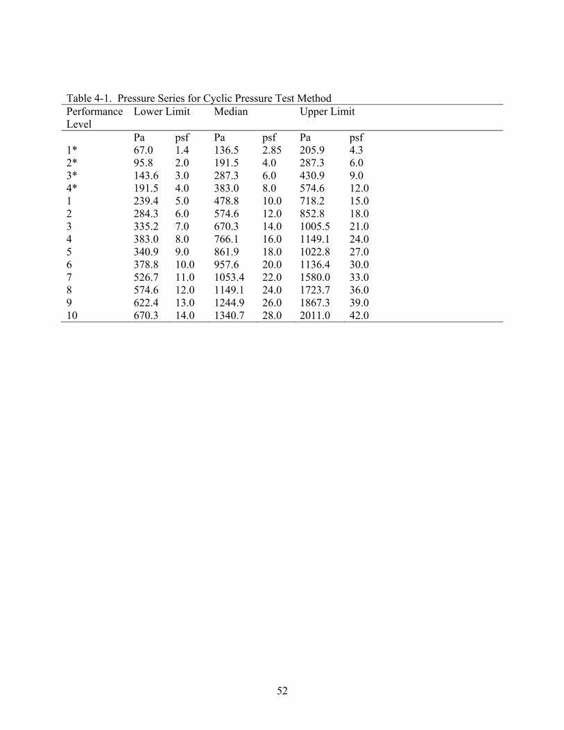
52
Table 4-1. Pressure Series for Cyclic Pressure Test Method Performance Level
Lower Limit Median Upper Limit
Pa psf Pa psf Pa psf 1* 67.0 1.4 136.5 2.85 205.9 4.3 2* 95.8 2.0 191.5 4.0 287.3 6.0 3* 143.6 3.0 287.3 6.0 430.9 9.0 4* 191.5 4.0 383.0 8.0 574.6 12.0 1 239.4 5.0 478.8 10.0 718.2 15.0 2 284.3 6.0 574.6 12.0 852.8 18.0 3 335.2 7.0 670.3 14.0 1005.5 21.0 4 383.0 8.0 766.1 16.0 1149.1 24.0 5 340.9 9.0 861.9 18.0 1022.8 27.0 6 378.8 10.0 957.6 20.0 1136.4 30.0 7 526.7 11.0 1053.4 22.0 1580.0 33.0 8 574.6 12.0 1149.1 24.0 1723.7 36.0 9 622.4 13.0 1244.9 26.0 1867.3 39.0 10 670.3 14.0 1340.7 28.0 2011.0 42.0

53
A
B

54
C
D Figure 4-1. Negative Pressure Chamber: A) Wall attached to the pressure chamber. Suction is
applied to the interior. B) Interior view of the wall specimen looking through 25.4 mm (1.0 in) acrylic. C) Rain Chamber containing the spray rack. D) Spray Rack is mounted to the wall exterior and sealed to collect water.

55
Figure 4-2. Electro-Pneumatic Valves
Figure 4-3. Calibration Catch Box

56
A
B
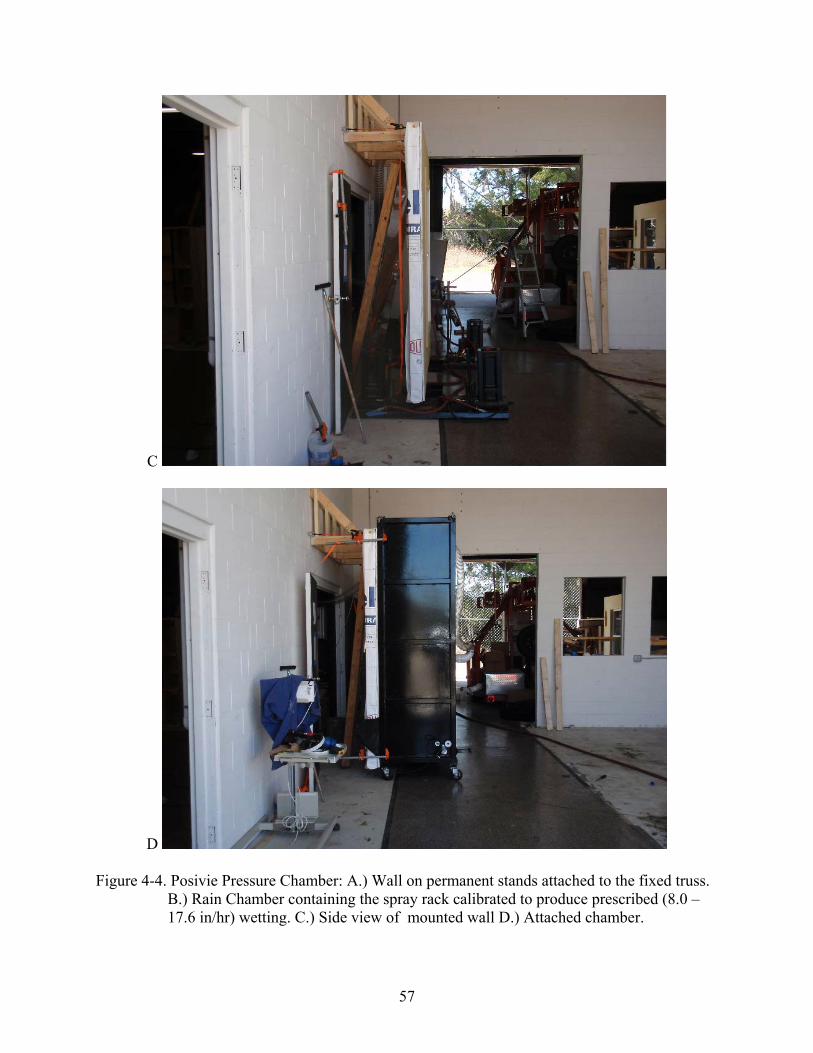
57
C
D Figure 4-4. Posivie Pressure Chamber: A.) Wall on permanent stands attached to the fixed truss.
B.) Rain Chamber containing the spray rack calibrated to produce prescribed (8.0 – 17.6 in/hr) wetting. C.) Side view of mounted wall D.) Attached chamber.
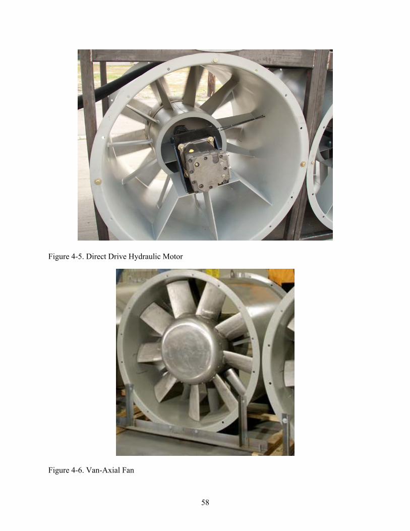
58
Figure 4-5. Direct Drive Hydraulic Motor
Figure 4-6. Van-Axial Fan

59
Figure 4-7. Nozzle
A

60
B
C Figure 4-8. Hurricane Simulator: A) Tuned inlets that connect to industrial vaneaxial fans. B)
Side view of simulator. The inlets and contraction can be removed for travel. C) Hurricane Simulator, residential model and specimen being prewetted.

61
Figure 4-9. Hydraulic Lift

62
Figure 4-10. Roof to Wall Connection
Figure 4-11. Air Caster Cart
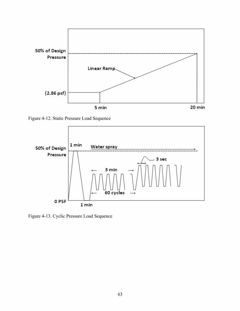
63
Figure 4-12. Static Pressure Load Sequence
Figure 4-13. Cyclic Pressure Load Sequence

64
Figure 4-14. Pressure Time History for Dynamic Test

65
A
B Figure 4-15. Loading Functions for Specimen 017C

66
1 10 3−× 0.01 0.1 1 100
0.5
1
1.5Flow rate variation with time
Time (min)
Flow
(L/m
in)
Figure 4-16. Flow Data for Increasing Load Curve (1149.0 Pa/ 24.0 psf step of specimen 017C)
0 1 2 3 40
0.1
0.2
0.3478.8 Pa (10 psf)574.6 Pa (12 psf)670.3 Pa (14 psf)766.1 Pa (16 psf)861.8 Pa (18 psf)909.7 Pa (19 psf)957.6 Pa (20 psf)1005 Pa (21 psf)1053 Pa (22 psf)1101 Pa (23 psf)1149 Pa (24 psf)1197 Pa (25 psf)1245 Pa (26 psf)1317 Pa (27.5 psf)
Flow vs Time
Time (min)
Flow
(L/m
in)
Figure 4-17. Last 25% of Data for All Pressure Steps (decreasing pressure curve of specimen
017C)

67
0 2 4 60
5
10
15Weight of water collected at time t
Time (min)
Wei
ght (
N)
Figure 4-18. Filtered Weight Data (1149.0 Pa/ 24.0 psf Step of Specimen 017C)
68
CHAPTER 5 SPECIMEN DESIGN AND CONSTRUCTION
The 16 wall specimens in table 5-1 were specifically constructed for this research, and are
discussed in this chapter. Eighteen additional wall specimens were constructed for a companion
project, which is detailed in [53]. The specimen matrix from that project is reprinted in table 5-2.
Each specimen has a unique combination of window operator type (see figures 5-5 through 5-8),
window dimensions, window material, window interface (i.e. different installation methods),
wall construction (wood frame and concrete masonry) and finish (decorative cementitious
coating, stucco, or fiber cement board). Among different variants chosen for the specimens,
considerations were also made to safely transport and store the specimens. Specimens were
designed to be tested post-cure, therefore they were stored in a warehouse where moisture and
sunlight were kept to a minimum in order to avoid unintended aging.
Under advisement from the task force it was decided that wall construction should be
limited to those typical in residential construction. Hence, wood framed walls were designed to
209 kmph (130mph) wind loading and concrete masonry walls were designed to 225 kmph
(140mph) wind loading.
Wood Frame Wall Specimens
Wood frame wall specimens were constructed offsite by a residential contractor using
design specifications provided by the American Forest & Paper Association (AF&PA) for
minimum code conforming wood frame walls. This was done with the intention of allowing the
walls to flex as much as permitted while still meeting deflection requirements set forth for stucco
finishes.
Once framed, these specimens were sheathed with 11.1 mm (7/16 in) oriented strand board
and the exterior was wrapped in commercial wrap. They were then finished in either fiber

69
cement board or a three coat (scratch, brown, and finish coats) stucco application, 13.0 mm (1/2
in) thick, over lath.
To simulate a wall to slab connection and to keep the walls from deflecting
unintentionally, each wall had a steel channel bolted to the bottom plate (see figure 5-1). Each
specimen was braced to the apparatus of every test, as well as the air caster cart, through the
channels. This precaution allowed handling and transportation of the specimen without damaging
the finish or any other component. Specimens were also kept elevated from the ground
approximately 101.6 mm (4.0 in) to access them for transport.
Masonry Wall Specimens
CMU wall specimens were built onsite, upon a rigid steel channel, by a licensed masonry
contractor. The CMU channel had #5 rebar welded at one fourth and three fourths of its length
to reinforce the masonry (see figure 5-3). Two 15.9 mm x 254.0 mm (5/8 in x 10.0 in) bolts were
also welded to the channel in order to resist any moment that was developed between the
masonry and the channel. Both the rebar and bolts are intended to help transfer load to the
channel, which in turn will transfer the load safely out of the specimen. Each CMU wall was also
equipped with grouted cells at the ends and at either side of the window rough opening (see
figure 5-4). Rough opening tolerance was in compliance with ACI 530.
Upon completion by the mason, the walls were finished with either a decorative
cementitious coating (varied from a paint thickness to 6.4 mm, 1/4 in), or a three coat (scratch,
brown, and finish coats) stucco application (13.0 mm, 1/2 in) over lath. The stucco application of
these specimens was selected with the assistance of Construction Code Specialists (CCS) and the
National Concrete Masonry Association (NCMA).

70
Testing Matrix
In residential construction it is common that a single home may contain a number of
different window sizes and operator types. With a wide range of window options available, the
selection of a window is often based on the architectural appearance as well as the functionality
it may serve in the desired application. These functions include egress requirements where
designers deem necessary, in case of an emergency, as well as giving occupants control of the
interior environment by natural ventilation. It would be unreasonable to test all possible
permutations of window size and type; therefore, under guidance of leading manufacturers,
careful consideration was made to limit the window variants to those most representative of
coastal construction practice in the south-eastern U.S. For operator types, single hung,
horizontal sliding, out-swing casement, and awning windows were selected for evaluation. Each
of which were limited to one representative window size based on minimum gateway sizes from
residential performance classes provided in AAMA/WDMA/CSA 101/I.S.2/A440 [38]. Within
similar operator types and dimensions there are also varying drainage types from window to
window (e.g., windows with built-in weep holes). Window material (aluminum and vinyl) was
also varied to observe their respective water infiltration resistance. In addition, all of the
windows were installed to manufacturer’s guidelines. Two installation methods for windows
were also employed (performances of which were analyzed in [53]).
Summary
Sixteen specimens were evaluated to observe their respective water infiltration resistance.
Each specimen was unique its combination of window; operator type, material, size, installation,
and wall; material, and finish. These individual permutations were subjected to the
aforementioned test methods and results were then analyzed.

71
Table 5-1. Test Specimen Matrix Specimen Wall Window Construction Finish Operator Dimension Material DP 001 Wood Stucco Fixed 110.49 cm X 158.75 cm 43.5” X 62.5”) Aluminum 40 006 Wood FCB Casement 90.17 cm X 151.13 cm (35.5” X 59.5” ) Aluminum 40 011 CMU DCC Hor. Sliding 158.75 cm X 110.49 cm (62.5” X 43.5”) Aluminum 45 020B CMU Stucco Fixed 110.49 cm X 158.75 cm (43.5” X 62.5”) Aluminum 40 022 Wood FCB Single Hung 110.49 cm X 158.75 cm (43.5” X 62.5”) Vinyl 40 025 Wood Stucco Casement 90.17 cm X 151.13 cm (35.5” X 59.5” ) Vinyl 40 032 CMU Stucco Hor. Sliding 158.75 cm X 110.49 cm (62.5” X 43.5”) Vinyl 40 019D CMU DCC Fixed 110.49 cm X 158.75 cm (43.5” X 62.5”) Aluminum 40 043 CMU DCC Single Hung 110.49 cm X 158.75 cm (43.5” X 62.5”) Aluminum 60 048 CMU Stucco Casement 90.17 cm X 151.13 cm (35.5” X 59.5” ) Aluminum 60 049 Wood Stucco Hor. Sliding 158.75 cm X 110.49 cm (62.5” X 43.5”) Aluminum 60 054 Wood FCB Awning 120.65 cm X 74.93 cm (47.5” X 29.5” ) Aluminum 60 064 CMU Stucco Single Hung 110.49 cm X 158.75 cm 43.5” X 62.5”) Vinyl 50 067 CMU DCC Casement 90.17 cm X 151.13 cm (35.5” X 59.5” ) Vinyl 55 070 Wood FCB Hor. Sliding 158.75 cm X 110.49 cm (62.5” X 43.5”) Vinyl 60 073 Wood Stucco Awning 120.65 cm X 74.93 cm (47.5” X 29.5” ) Vinyl 60

72
Table 5-2. Test Specimen Matrix Specimen Wall Window Construction Finish Operator Dimension Material DP 017 Wood Stucco Fixed 110.5 cm X 158.8 cm (43.5” X 62.5”) Aluminum 40 017B Wood Stucco Fixed 110.5 cm X 158.8 cm (43.5” X 62.5”) Aluminum 40 017C Wood Stucco Single Hung 110.5 cm X 158.8 cm (43.5” X 62.5”) Aluminum 55 017D Wood Stucco Fixed 110.5 cm X 158.8 cm (43.5” X 62.5”) Aluminum 40 017E Wood Stucco Fixed 110.5 cm X 158.8 cm (43.5” X 62.5”) Aluminum 40 018 Wood FCB Fixed 110.5 cm X 158.8 cm (43.5” X 62.5”) Aluminum 40 018B Wood FCB Fixed 110.5 cm X 158.8 cm (43.5” X 62.5”) Aluminum 40 018C Wood FCB Fixed 110.5 cm X 158.8 cm (43.5” X 62.5”) Aluminum 40 018D Wood FCB Fixed 110.5 cm X 158.8 cm (43.5” X 62.5”) Aluminum 40 018E Wood FCB Fixed 110.5 cm X 158.8 cm (43.5” X 62.5”) Aluminum 40 019 CMU DCC Fixed 110.5 cm X 158.8 cm (43.5” X 62.5”) Aluminum 40 019B CMU DCC Fixed 110.5 cm X 158.8 cm (43.5” X 62.5”) Aluminum 40 019C CMU DCC Fixed 110.5 cm X 158.8 cm (43.5” X 62.5”) Aluminum 40 035 CMU DCC Fixed 120.7 cm X 74.9 cm (47.5” X 29.5” ) Vinyl 52.7 020 CMU Stucco Fixed 110.5 cm X 158.8 cm (43.5” X 62.5”) Aluminum 40 016 CMU Stucco Fixed 120.7 cm X 74.9 cm (47.5” X 29.5” ) Aluminum 52.7 020C CMU Stucco Fixed 110.5 cm X 158.8 cm (43.5” X 62.5”) Aluminum 40 020D CMU Stucco Fixed 110.5 cm X 158.8 cm (43.5” X 62.5”) Aluminum 40

73
A Figure 5-1. Bolted Channels to Wood Frame Walls

74
Figure 5-2. Designs for Wood Frame Walls.

75
A
B Figure 5-3. CMU Wall Specimen Stabilization Channel

76
Figure 5-4. Designs for CMU Wall

77
Figure 5-5. Awning Window
Figure 5-6. Casement Window

78
Figure 5-7. Single Hung Window
Figure 5-8. Horizontal Sliding Window

79
CHAPTER 6 RESULTS
The specimens were subjected to four independent rounds of testing to investigate the
effects of differing loading conditions. The specimens were monitored for instances of water
intrusion, which is defined as “any liquid water observed from the interior side of the wall
assembly to have bypassed the moisture barrier of the window/wall system.” This chapter
discusses the repeatability of test results, its relationship to damage accumulation, and compares
the diagnostic abilities of the various tests to detect leakage. The water penetration resistance of
each operator type is evaluated, with particular focus on the performance of compression and
sliding seals. Finally, the results of positive and negative pressure testing are compared to
investigate whether or not anecdotal claims that the direction of pressure loading affects leakage
and can be repeated experimentally.
Assessment of Repeatability during the Test Series
Test specimens were subjected to three water penetration resistance test methods with
different pressure loading scenarios, and had to be transported to each of the testing apparatuses
and their storage locations. Thus it was necessary to determine if successive testing and/or
transport caused any permanent damage before results could be compared.
Two measures were taken to obviate this issue. First, the maximum pressure applied was
intentionally set at half of the window’s rated design pressure (DP) to avoid permanent damage
to the wall assembly, seals, and window components, which would in turn change water
penetration resistance. Second, a custom built air caster cart was developed to literally float the
walls from one location to the next. This system worked well; the investigators have no cause to
believe that any of the specimens were damaged during transport.

80
To address the potential outcomes from successive testing, the first test was repeated after
the static, cyclic, and dynamic tests (performed in this order). All other factors being equal (e.g.,
identical mechanical response of the valves, temperature, relative humidity, etc.), the two static
pressure tests should produce the same results if the specimens were not permanently damaged in
previous tests.
The results of the first and last uniform static pressure tests are now discussed. The test
data for this project may be found in tables 6-1 and 6-2 (The reader should refer to [53] for the
test data from the companion project specimens found in table 5-2). Table 6-1 contains initial
infiltration paths that occurred at recorded pressures during the separate rounds of static testing.
Each row in the tables corresponds to an isolated location where infiltration was observed.
Table 6-2 contains the number of leakage paths observed in each test.
Each specimen that exhibited either a large change in the pressure threshold associated
with the first sign of leakage and/or number of leaks from the first static pressure test to the last
were reanalyzed using other recording methods used during testing (e.g. photographic and
video), to determine if indeed damage accumulation had occurred. The salient points from the
re-inspection are listed below.
• Specimens 019, 020B and 070 exhibited new infiltration paths through the window/wall interface during the second static pressure test, demonstrating damage. These test results will be disregarded.
• Specimen 011 exhibited new infiltration paths through the window assembly during the second static pressure test. Its test results will be disregarded.
• Specimen 067 exhibited new infiltration paths through the precast sill at a lower pressure in the second static test, demonstrating damage. Its test results will be disregarded.
• Specimen 064 should be identified as the only specimen that was subjected to 1675.8 Pa (35.0 psf) during the dynamic pressure test. These pressures were substantially beyond the test protocol of 50% of the design pressure (1197.0 Pa /25.0 psf), hence the specimen was deemed to have sustained damage and its results will be disregarded.

81
• During the initial static pressure testing, research personnel prematurely terminated 2 of the 9 specimen tests (032 and 049) because of concern that the rate of water infiltration might damage the specimen or overload the drainage capacity of the testing apparatus. These were the first tests performed in this project. Further investigation showed that rates of infiltration observed were typical and no damage had occurred. In subsequent tests, the testing was carried out through the full duration.
• Regarding specimens 020D and 025, it is the opinion of the research team that the infiltration paths documented in the second static pressure test were minute and possibly overlooked in the first static pressure test. They are judged to not be indicative of permanent damage.
Summarizing, six out of the 34 wall specimens exhibited a change in performance
sufficiently large to warrant their removal from subsequent analysis. For practical purposes it
may be assumed that the remaining specimens exhibited repeatable performance characteristics
and that the results are intercomparable.
Comparison of Results from Static, Cyclic and Dynamic Test Methods
Comparing the diagnostic ability of static, cyclic and dynamic testing was the principal
objective of this project. The ultimate goal is to determine if full-scale dynamic testing should
replace the simplified test methods used today or if the simplified tests are sufficient to evaluate
water penetration resistance in their current form (or with minor modifications). It is important
to note that these questions are being asked in the context of “systems” testing. Today, products
are tested in isolation, which many professionals feel is a major shortcoming.
This new understanding is the key to improving simplified, but highly repeatable, test
protocols to bridge the gap between what can be physically accomplished and duplicated in
commercial testing labs, and what actually occurs in a windstorm (or perhaps, a research-grade
windstorm simulation facility).
Dynamic pressure testing using the hurricane simulator was assumed to be the better
representation of loads exhibited by a windstorm, although it is noted that there still remain many
deficiencies with the ability of full-scale simulators to recreate hurricane force winds and wind-

82
driven rain. The field is still in its infancy, and projects such as this one are required for
experimentalists to hone these techniques. That being said, the system was calibrated to a
simplified representation of actual field data collected in hurricanes and true “wind-driven” rain
was applied (in contrast to the pressure chamber tests where water is sprayed on the specimen
while a pressure gradient is created across the specimen).
Table 6-3 contains information about the specimens that exhibited leakage in the first three
rounds of testing. Specimens that did not leak or experienced permanent damage during the
testing are omitted. The number of common leakage paths identified through both dynamic and
static testing is listed in the first data column. The second data column contains the number of
leakage paths observed in the cyclic and dynamic tests. The dynamic test results compare more
favorably to the cyclic test than the static pressure test. Table 6-4 contains the number of leakage
paths observed in static and cyclic tests that were not observed in the dynamic testing. It also
contains the number of leakage paths observed exclusively in the dynamic test, but did not
manifest in the static or cyclic tests. The counts are nearly identical (7,7,8) for the three test
methods, which indicates there is no clear advantage to the dynamic testing.
Summarizing, adapting conventional testing techniques to holistically test wall systems
appears to work well based on the results of these experiments. It should be noted that this
observation is only strictly valid for the type of construction evaluated in this research, namely
single-family residential finished wall systems with integrated fenestration.
Intercomparison of Window Operator Water Penetration Resistance
The water penetration resistance of the specimens with operable windows is listed in table
6-5. They are grouped by operator type: awning (016, 035, 054, 073), casement (006, 025, 048),
single hung (017C, 022, and 043) and horizontal sliding (032, 049). Summary statistics are
provided in table 6-6.
83
All of the operable windows met the requirement that the water penetration resistance must
be greater than or equal to the 15% of the design pressure (stipulated in Section 5.3.3.2 of
AAMA/WDMA/CSA 101/I.S.2/A440 [38] and Section 5.2.6 of TAS 202-94 [47] in Florida)
using the leakage definition set forth in ASTM E 331. ASTM E 331 states that leakage is the
“penetration of water beyond a plane parallel to the glazing (the vertical plane) intersecting the
innermost projection of the test specimen, not including interior trim and hardware, under the
specified conditions of air pressure difference across the specimen.” Water was observed to
collect in the bottom slider track earlier in the test, thus for completeness, a second pressure
threshold is included in table 6-5. This water would have to reach a sufficient elevation head to
overtop the back dam to qualify as leakage using the ASTM E 331 definition.
The results summarized in table 6-5 demonstrate that those windows that use a
compression seals exhibit better watertightness than the sliding seal windows. None of the
awning windows leaked, which based on the limited results of this research, indicates that the
awning style is the preferable option for area prone to severe wind driven rain. Two of the three
casement windows leaked, but a larger pressure than the sliding seal windows. The single hung
windows leaked at the lowest pressures, but the flow rate through the horizontal sliders was
much greater.
Operable Window Infiltration Rate Testing
The testing application standards typically allow for two load configurations. A suction
load can be applied to the interior of the specimen, or a positive pressure can be applied to the
exterior of the specimen. In either case, the opposite side of the specimen is open to the free
atmosphere. Thus, all other factors being the same, the pressure gradient should be the same
across the specimen.

84
It has been speculated that the direction of loading can affect the water penetration
resistance (vis-à-vis test results on identical products using both load scenarios that do not
agree). This issue was specifically addressed in one of the stakeholder oversight meetings,
which prompted further testing using a positive pressure chamber (all of the tests results
discussed so far were obtained using a negative pressure chamber).
Four test specimens were tested again using the two pressure chambers. The loads were
incremented in a stepwise pattern while the infiltration rate, through the window assembly alone,
was monitored. Results from the testing, which appear in figure 6-1 and figure 6-2, are virtually
identical. It should be noted that because the infiltration rate was measured through the window,
specimen 070 (deemed to have sustained damage through the window wall interface) was
reintroduced. It should also be noted that compression seal operator type windows were
intentionally left out of this experiment because of the difficulty of collecting and measuring the
minute volumes of infiltrated water (e.g. figure 6-3). These data suggest that there is no basis to
the claim that the direction of loading affects the infiltration rate given that flow rates were
nearly identical for a large range of pressures. Moreover, the lowest pressure threshold for
which infiltration occurred for both tests compared very favorably. A summary of infiltration
flow rates is given in figure 6-4 and typical infiltration paths are provided in figures 6-5 through
6-8.
Least squares curve fitting was performed on the data. The infiltration rate through the
hung windows appears to be directly proportional to the pressure load, while the relationship
between the pressure and infiltration rate through the horizontal sliders is non-linear. Equations
for flow and their respective coefficients of determination are as shown in equations 6-1 through
6-4 for specimens 017C, 022, 049, and 070 respectively. P-Pressure(Pa), Q-Flow rate (L/min).

85
76.1028.3 5 −×= − PQ (6-1) 964.02 =R
76.01090.1 3 −×= − PQ (6-2) 982.02 =R
PP eeQ 01.04108.6 108.367.0
4 −−× ×−=−
(6-3) 979.02 =R
PP eeQ
34 102.8107.3 11.2461.0−− ×−× −= (6-4)
995.02 =R
An investigation as to whether water penetration behavior is dependant on prior load rate
(i.e. target pressures are achieved from greater or lower pressures) was also conducted. In
figures 6-1 and 6-2 the infiltration rates are compared as loads are applied in a step wise fashion.
It was theorized that once a specimen was brought up to a certain pressure, infiltration rates at
any subsequent lower pressure would be greater; however, the data in these figures suggests that
infiltration rates are independent of prior pressure levels.
Summary
Specimens were subjected to static, cyclic as well as amplitude- and frequency-modulated
sinusoidal pressure load sequences, followed by a repeat of the static test to ensure that the
specimens were not permanently damaged during testing. Six of the 34 test specimens exhibit
different leakage characteristics between the first and last tests. These results were omitted from
further analysis (with the exception of specimen 022, which was reintroduced for isolated
window testing). It was found that adapting conventional testing techniques to holistically test
wall systems appears to work well based on the results of these experiments. Compression seal
windows are more watertight than sliding seal windows, with awning windows being the
superior option. Finally, positive and negative pressure loading were performed on test

86
specimens. It was shown that the direction of loading has no effect on the infiltration rates and
pressure threshold associated with the first sign of leakage.

87
Table 6-1. Time to Leakage and Corresponding Pressure in Uniform Static Pressure Tests
Specimen First Static Test Second Static Test Difference Time Pa psf Time Pa psf Pa psf 001 10:54 450 9 DNL DNL DNL N/A N/A 016 DNL DNL DNL DNL DNL DNL N/A N/A 017 DNL DNL DNL DNL DNL DNL N/A N/A 018 18:17 867 18 DNL DNL DNL N/A N/A 018B DNL DNL DNL DNL DNL DNL N/A N/A 018C DNL DNL DNL DNL DNL DNL N/A N/A 018D DNL DNL DNL DNL DNL DNL N/A N/A 018E DNL DNL DNL DNL DNL DNL N/A N/A 019B DNL DNL DNL DNL DNL DNL N/A N/A 019D DNL DNL DNL DNL DNL DNL N/A N/A 020 DNL DNL DNL DNL DNL DNL N/A N/A 035 DNL DNL DNL DNL DNL DNL N/A N/A 048 16:22 1489 31 DNL DNL DNL N/A N/A 054 03:13 1226 26 DNL DNL DNL N/A N/A 073 04:51 139 3 DNL DNL DNL N/A N/A 020D 10:45 503 11 11:09 522 11 19 0 017C 15:00 948 20 15:40 977 20 29 1 064 08:40 402 8 11:22 431 9 29 1 043 09:12 474 10 09:56 527 11 53 1 049 11:25 847 18 10:57 795 17 -53 -1 025 12:40 565 12 11:36 503 11 -62 -1 017B 17:45 843 18 20:00 958 20 115 2 019C 07:20 273 6 06:00 192 4 -81 -2 017E 06:20 215 5 03:18 139 3 -77 -2 020C 06:38 239 5 04:15 139 3 -101 -2 006 15:15 699 15 10:40 828 17 129 3 032 09:30 527 11 11:11 675 14 148 3 017D 19:30 943 20 17:27 819 17 -124 -3 011 10:30 493 10 09:11 369 8 -124 -3 022 07:21 345 7 10:25 603 13 259 5 070 10:12 450 9 11:49 728 15 278 6 019 15:00 958 20 08:55 354 7 -603 -13 067 15:34 977 20 03:57 139 3 -838 -18 020B DNL DNL DNL 11:10 474 10 N/A N/A
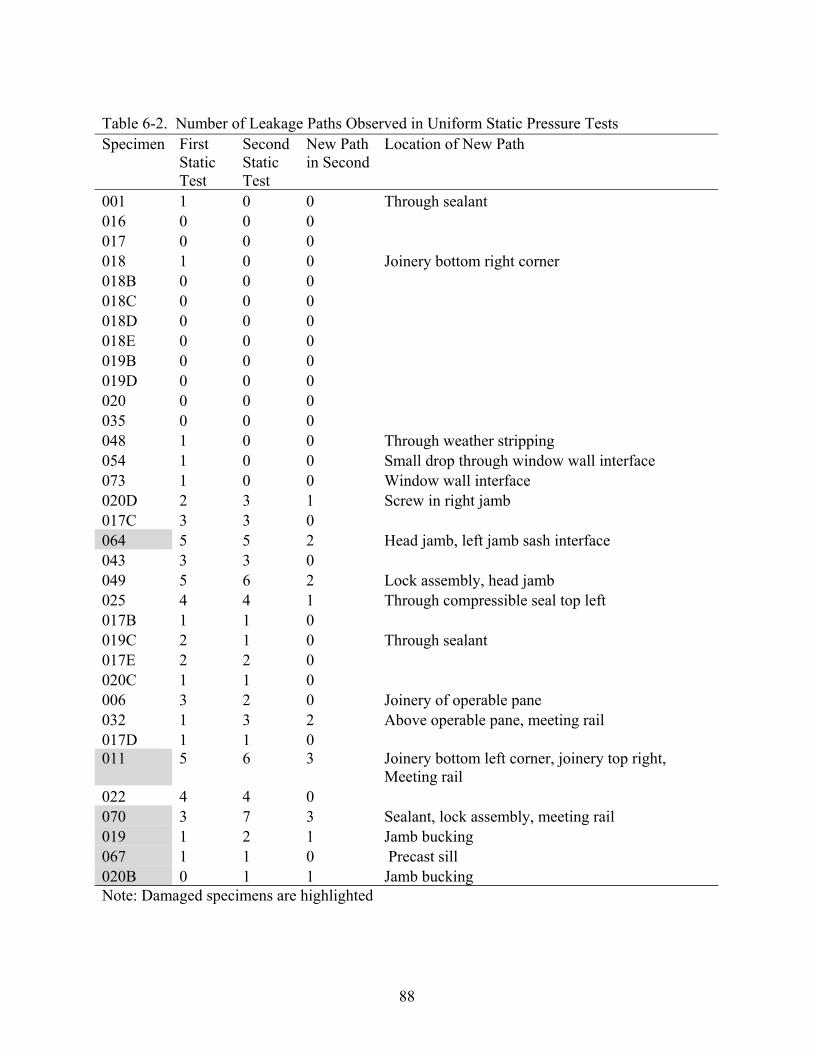
88
Table 6-2. Number of Leakage Paths Observed in Uniform Static Pressure Tests Specimen First
Static Test
Second Static Test
New Path in Second
Location of New Path
001 1 0 0 Through sealant 016 0 0 0 017 0 0 0 018 1 0 0 Joinery bottom right corner 018B 0 0 0 018C 0 0 0 018D 0 0 0 018E 0 0 0 019B 0 0 0 019D 0 0 0 020 0 0 0 035 0 0 0 048 1 0 0 Through weather stripping 054 1 0 0 Small drop through window wall interface 073 1 0 0 Window wall interface 020D 2 3 1 Screw in right jamb 017C 3 3 0 064 5 5 2 Head jamb, left jamb sash interface 043 3 3 0 049 5 6 2 Lock assembly, head jamb 025 4 4 1 Through compressible seal top left 017B 1 1 0 019C 2 1 0 Through sealant 017E 2 2 0 020C 1 1 0 006 3 2 0 Joinery of operable pane 032 1 3 2 Above operable pane, meeting rail 017D 1 1 0 011 5 6 3 Joinery bottom left corner, joinery top right,
Meeting rail 022 4 4 0 070 3 7 3 Sealant, lock assembly, meeting rail 019 1 2 1 Jamb bucking 067 1 1 0 Precast sill 020B 0 1 1 Jamb bucking Note: Damaged specimens are highlighted

89
Table 6-3. Leakage Paths Observed in Static, Cyclic and Dynamic Tests Specimen Similar Paths in Primary
Static and Dynamic Tests Similar Paths in Cyclic and Dynamic Tests
001 2 2 006 2 2 017B 0 0 017C 2 3 017D 0 0 017E 1 1 018 0 1 019C 2 2 020C 0 1 020D 2 4 022 3 4 025 3 4 032 1 3 043 3 3 048 1 0 049 5 4 054 0 0 073 1 1 Total 28 35

90
Table 6-4. Leakage Path Detection Comparison Specimen Paths in
Static Not Detected in Dynamic
Paths in Cyclic Not Detected in Dynamic
Paths Detected Exclusively in Dynamic
Description of Paths Not Detected in Dynamic
Description of Paths Detected Exclusively in Dynamic
001 1 0 1 Through sealant at window fin
Through sealant at window fin
006 0 1 0 Through joinery 017 0 0 3 Sill joinery, Jamb
wall interface, Joinery of head jamb
017B 1 2 0 Window/flashing interface
017C 0 0 0 017D 1 1 0 Sealant/flashing
interface
017E 0 0 0 018 1 0 0 Sealant/flashing
interface
019C 0 0 0 020C 1 1 0 Skip in sealant 020D 0 0 0 022 0 0 1 Meeting rail 025 1 1 1 Crank assembly Through joinery 032 0 0 1 Top of meeting rail 043 0 0 0 048 0 0 0 049 0 0 1 Through joinery of
operable pane at top right corner
054 1 1 0 Window/flashing interface
073 0 0 0 Total 7 7 8

91
Table 6-5. Evaluation of Operable Windows With Respect to Pressure of First Leakage Path Operator type Pressures (Pa/psf) % of DP Static 2nd Static Lowest DP(Pa/psf) Awning 054 DNL DNL DNL 2872.8/60 N/A 016 DNL DNL DNL 2523.3/52.7 N/A 073 DNL DNL DNL 2872.8/60 N/A 035 DNL DNL DNL 2523.3/52.7 N/A Casement (067 removed) 048 DNL DNL DNL 2872.8/60 N/A 006 699.0/14.6 828.3/17.3 699.0/14.6 1915.2/40 36.5% 025 565.0/11.8 502.7/10.5 502.7/10.5 1915.2/40 26.3% Single Hung (064 removed) 043 474.0/9.9 526.7/11.0 474.0/9.9 2872.8/60 16.5% 017C 670.32/14.0 1149.1/24.0 670.32/14.0 2633.4/55 25.5% 022 890.6/18.6 785.2/16.4 785.2/16.4 1915.2/40 41.0% Hor. Sliding (leak per definition in Chapter 6* 011 and 070 removed) 049 138.9/2.9 138.9/2.9 138.9/2.9 2872.8/60 4.8% 032 138.9/2.9 138.9/2.9 138.9/2.9 1915.2/40 7.3% Hor. Sliding (leak defined per ASTM E 331**, 011 and 070 removed) 049 847.5/17.7 794.8/16.6 794.8/16.6 2872.8/60 27.7% 032 N/A 675.1/14.1 675.1/14.1 1915.2/40 35.3% Note: Two sets of data for Horizontal Sliding operator type to differentiate the definitions of leakage. * Any liquid water observed from the interior side of the wall assembly to have bypassed the moisture barrier of the window/wall system ** Penetration of water beyond a plane parallel to the glazing (the vertical plane) intersecting the innermost projection of the test specimen, not including interior trim and hardware, under the specified conditions of air pressure difference across the specimen
\
Table 6-6 Average Percentage of Design Pressure for Which Leakage Occurred Operator type Average percentage of DP when infiltration occurred Awning Did not leak Casement 37.6% (Note: One did not leak and one was damaged) SH/DH 27.7% Horizontal Sliding 6.1% (first sign of leakage) Horizontal Sliding 31.5% (per ASTM E 331)
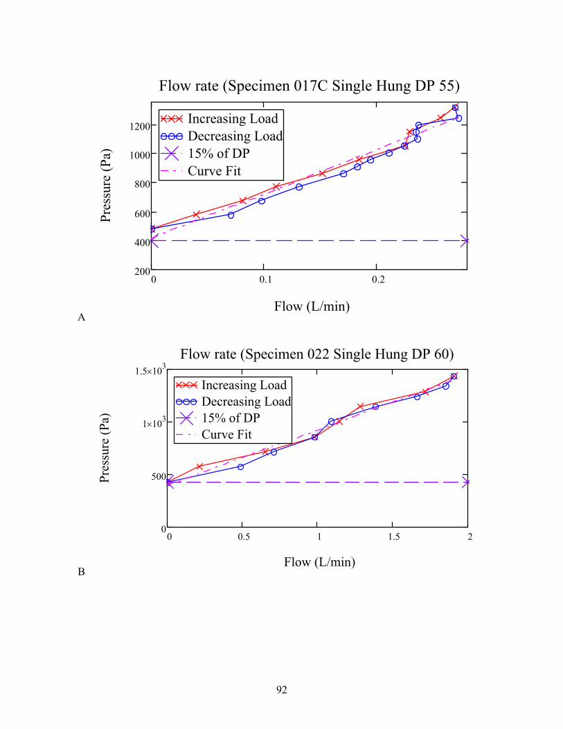
92
A
0 0.1 0.2200
400
600
800
1000
1200Increasing LoadDecreasing Load15% of DPCurve Fit
Flow rate (Specimen 017C Single Hung DP 55)
Flow (L/min)
Pres
sure
(Pa)
B
0 0.5 1 1.5 20
500
1 103×
1.5 103×Increasing LoadDecreasing Load15% of DPCurve Fit
Flow rate (Specimen 022 Single Hung DP 60)
Flow (L/min)
Pres
sure
(Pa)

93
C
0 1 20
500
1000
1500
Increasing LoadDecreasing Load15% of DPCurve Fit
Flow rate (Specimen 049 Horizontal Slider DP 75)
Flow (L/min)
Pres
sure
(Pa)
D
0 0.5 10
500
1000
1500Increasing LoadDecreasing Load15% of DPCurve Fit
Flow rate (Specimen 070 Horizontal Slider DP 60)
Flow (L/min)
Pres
sure
(Pa)
Figure 6-1. Load and Unload Curves for Operable Windows Under Negative Load

94
A
0 0.1 0.2200
400
600
800
1 103×
1.2 103×
1.4 103×Increasing LoadDecreasing Load15% of DPCurve Fit
Flow rate (Specimen 017C Single Hung DP 55)
Flow (L/min)
Pres
sure
(Pa)
B
0 1 2 3 40
500
1 103×
1.5 103×
2 103×
2.5 103×Increasing LoadDecreasing Load15% of DPCurve Fit
Flow rate (Specimen 022 Single Hung DP 60)
Flow (L/min)
Pres
sure
(Pa)

95
C
0 1 20
500
1 103×
1.5 103×
Increasing LoadDecreasing Load15% of DPCurve Fit
Flow rate (Specimen 049 Horizontal Slider DP 75)
Flow (L/min)
Pres
sure
(Pa)
D
0 0.5 10
500
1 103×
1.5 103×Increasing LoadDecreasing Load15% of DPCurve Fit
Flow rate (Specimen 070 Horizontal Slider DP 60)
Flow (L/min)
Pres
sure
(Pa)
Figure 6-2. Load and Unload Curves for Operable Windows Under Positive Load (Curve-fit is from negative pressure testing)

96
.
Figure 6-3. Water Infiltrated at the End of Static Pressure Test (bottom left corner of specimen 006/ Casement window)

97
Figure 6-4. Comparison of Performance of Operable Window Assemblies

98
Figure 6-5. Typical Infiltration for Casement Windows (Bottom left corner above sill)
Figure 6-6. Typical Infiltration for Single Hung Windows (Bottom right corner above sill)

99
Figure 6-7. Typical Infiltration for Single Hung Windows (Left side of meeting rail)
Figure 6-8. Typical Infiltration for Horizontal Sliding Windows
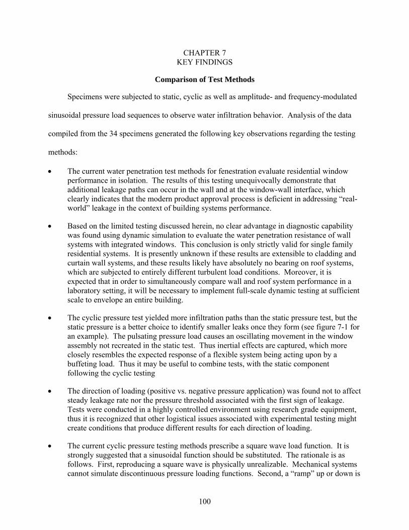
100
CHAPTER 7 KEY FINDINGS
Comparison of Test Methods
Specimens were subjected to static, cyclic as well as amplitude- and frequency-modulated
sinusoidal pressure load sequences to observe water infiltration behavior. Analysis of the data
compiled from the 34 specimens generated the following key observations regarding the testing
methods:
• The current water penetration test methods for fenestration evaluate residential window performance in isolation. The results of this testing unequivocally demonstrate that additional leakage paths can occur in the wall and at the window-wall interface, which clearly indicates that the modern product approval process is deficient in addressing “real-world” leakage in the context of building systems performance.
• Based on the limited testing discussed herein, no clear advantage in diagnostic capability was found using dynamic simulation to evaluate the water penetration resistance of wall systems with integrated windows. This conclusion is only strictly valid for single family residential systems. It is presently unknown if these results are extensible to cladding and curtain wall systems, and these results likely have absolutely no bearing on roof systems, which are subjected to entirely different turbulent load conditions. Moreover, it is expected that in order to simultaneously compare wall and roof system performance in a laboratory setting, it will be necessary to implement full-scale dynamic testing at sufficient scale to envelope an entire building.
• The cyclic pressure test yielded more infiltration paths than the static pressure test, but the static pressure is a better choice to identify smaller leaks once they form (see figure 7-1 for an example). The pulsating pressure load causes an oscillating movement in the window assembly not recreated in the static test. Thus inertial effects are captured, which more closely resembles the expected response of a flexible system being acting upon by a buffeting load. Thus it may be useful to combine tests, with the static component following the cyclic testing
• The direction of loading (positive vs. negative pressure application) was found not to affect steady leakage rate nor the pressure threshold associated with the first sign of leakage. Tests were conducted in a highly controlled environment using research grade equipment, thus it is recognized that other logistical issues associated with experimental testing might create conditions that produce different results for each direction of loading.
• The current cyclic pressure testing methods prescribe a square wave load function. It is strongly suggested that a sinusoidal function should be substituted. The rationale is as follows. First, reproducing a square wave is physically unrealizable. Mechanical systems cannot simulate discontinuous pressure loading functions. Second, a “ramp” up or down is

101
required to shift from one pressure state to another. As the duration of this ramp becomes shorter, the possibility of overshooting the target pressure value becomes larger, which is highly problematic. Third, the most common practice in atmospheric science and wind engineering is to decompose wind and pressure into sinusoidal functions using a Fourier transform. Deviating from this practice is unnecessary and puts unnecessary experimental burden on the testing laboratories.
Performance of Window Assemblies
As expected, operable window assemblies exhibit larger rates of water infiltration than
fixed windows. The test methods performed aimed to observe the effects that different
components had on the water penetration resistance of the window assembly. Among the
variables were wall material, window material, window design pressure, and window operator
type. Analysis of the data compiled from the 16 specimens that had operable windows installed,
generated the following key observations regarding the water penetration resistance:
• Specimens utilizing windows with compression seals performed better than those with sliding seals (table 6-6). Awnings performed the best of all specimens. In windows utilizing sliding seals, it was observed that the operable pane separated from the seal. This allowed a gap for air and water to intrude along the interface (e.g. through jamb/sash interface for single hung window)
• Compression seal operator type windows exhibited a substantial improvement in relative water penetration resistance (i.e. infiltration occurring at percentages of design pressure) with increased design pressure: Of the eight different compression seal operator type windows only the lowest rated (1915.0 Pa/ 40.0 psf design pressure) exhibited water infiltration (table 6-5). However it is unclear whether sliding seal operator type windows demonstrate depreciation or improvement in relative water penetration resistance (i.e. infiltration occurring at percentages of design pressure) with increased design pressure.
• Design pressure should not be considered an indication of performance in regards to infiltration flow rate, particularly given higher pressures: It is more of a dependence on operator type. During these tests it was observed in some cases, that the highest design pressure rated specimen exhibited the highest flow rates. Figure 6-1 shows that horizontal sliding operator type windows follow a non linear pressure to flow relationship, and single hung operator type windows follow a first order, linear pressure to flow relationship.

102
A
B Figure 7-1. Infiltration Paths Through the Right Side of the Operable Sill of Specimen #032. A)
End of the cyclic test B) End of the static test.

103
APPENDIX A: SPECIMEN RECORDS
Figure A1-1. Specimen 001 Records

104
Figure A1-2. Specimen 006 Records

105
Figure A1-3. Specimen 011 Records

106
Figure A1-4. Specimen 019D Records
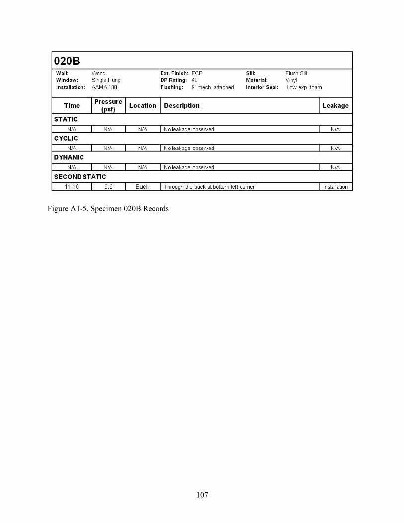
107
Figure A1-5. Specimen 020B Records
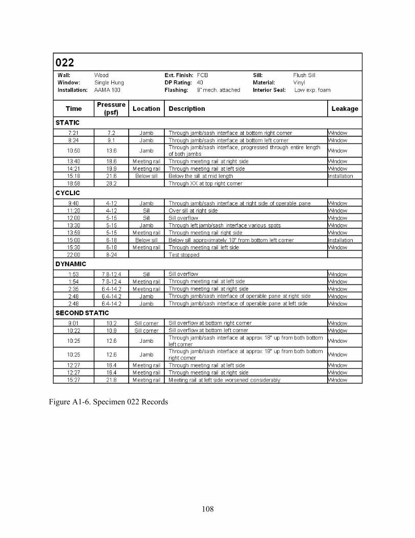
108
Figure A1-6. Specimen 022 Records

109
Figure A1-7. Specimen 025 Records
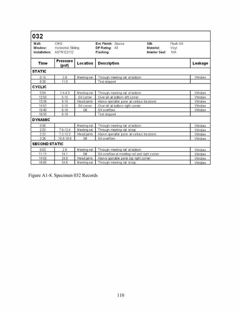
110
Figure A1-8. Specimen 032 Records

111
Figure A1-9. Specimen 043 Records

112
Specimen 048
Figure A1-10. Specimen 048 Records

113
Figure A1-11. Specimen 049 Records

114
Figure A1-12. Specimen 054 Records

115
Figure A1-13. Specimen 064 Records

116
Figure A1-14. Specimen 067 Records

117
Figure A1-15. Specimen 070 Records

118
Figure A1-16. Specimen 073 Records

119
LIST OF REFERENCES
[1] NCDC. Billion Dollar Climate and Weather Disasters, 1980-2008. National Climatic Data Center (NCDC) 2008
[2] Insurance Services Office (ISO), 545 Washington Boulevard, Jersey City, NJ 07310
[3] Pielke RA, Landsea CW. Normalized Hurricane Damage in the United States: 1900-2005. Natural Hazards Review 2007. 9 (1); 621-631.
[4] Blake ES, Rappaport EN, Landsea CW. NWS TPC-5 The Deadliest, Costliest, and Most Intense United States Tropical Cyclones from 1851 to 2006 (and other frequently requested hurricane facts). National Weather Service; 2007.
[5a] US Census Bureau. Interim Projections of the Total Population for the United States and States: April 1, 2000 to July 1, 2030. US Census Bureau; 2008.
[5b] US Census Bureau. Cumulative Estimates of Resident Population Change for the United States, Regions, States, and Puerto Rico and Region and State Rankings: April 1, 2000 to July 1, 2008. US Census Bureau; 2008.
[6] Hartwig RP. Florida Property Insurance Facts. III Institute for Insurance Information; 2008.
[7] Hartwig RP. Florida Case Study: Economic Impacts of Business Closures in Hurricane Prone Areas. III Institute for Insurance Information; 2002.
[8] Executive Order 92-291. Governor’s Commission on Hurricane Andrew, Executive order 92-291. Governor’s Disaster Planning and Response Review Committee; 1992.
[9] FEMA. Building Performance: Hurricane Andrew in Florida. Federal Emergency Management Agency; 1992.
[10] FEMA. Summary Report on Building Performance: 2004 Hurricanes. Federal Emergency Management Agency; 2005
[11] NCDC. Climate of 2004 Atlantic Hurricane Season. National Climatic Data Center (NCDC); 2004.
[12] NCDC. Climate of 2005 Atlantic Hurricane Season. National Climatic Data Center (NCDC); 2005.
[13] Katsaros JD, Hardman BG. Failed Fenestration: New Materials Require New Techniques. In: Thermal Performance of the Exterior Envelopes of Whole Buildings X International Conference Proceedings, ASHRAE; 2007.
[14] Simpson RH. The Hurricane Disaster Potential Scale. Weatherwise, 1974; 27: 169-186.
[15] NOAA. Data for hurricane charts gathered from:

120
http://csc-s-maps-q.csc.noaa.gov/hurricanes/viewer.html . National Oceanographic and Atmospheric Association; Accessed 7-12-2008.
[16] Sparks PR, Schiff SD, Reinhold TA. Wind Damage to Envelopes of houses and Consequent Insurance Losses. Journal Wind Engineering and Industrial Aerodynamics, 1994; 53 (1-2): 145-155.
[17] Gurley K, Burton J, Abdullah M, Masters F, Reinhold T. Post 2004 Hurricane Field Survey- an Evaluation of the Relative Performance of the Standard Building Code and the Florida Building Code. Department of Civil and Coastal Engineering, College of Engineering, University of Florida, Structures Research Communication No. 53102-2, 2006.
[18] Blocken B, Carmeliet J. Spatial and Temporal Distribution of Driving Rain On A Low-Rise Building. Wind and Structures, 2002; 5(5): 441-462.
[19] Blocken B, Carmeliet J. A Review of Wind-Driven Rain Research in Building Science. Journal of Wind Engineering and Industrial Aerodynamics, 2004; 92: 1079–1130.
[20] Best AC. The Size Distribution of Raindrops. Quart. J. Roy. Meteorological Society, 1950; 76 (327): 16-36.
[21] Mualem Y, Assouline S. Mathematical Model for Rain Drop Distribution and Rainfall Kinetic Energy. Trans. Amer. Soc. Agric. Eng, 1986; 29 (2): 494-500.
[22] Karagiozis A, Hadjisophocleous G, Cao S. Wind Driven Rain Distributions on Two Buildings. Journal of Wind Engineering and Industrial Aerodynamics, 1997; 67(8): 559-572.
[23] Choi ECC. Simulation of Wind Driven Rain Around the Building. Journal of Wind Engineering and Industrial Aerodynamics, 1993; 46-47: 721-729.
[24] Choi ECC. Parameters Affecting the Intensity of Wind Driven Rain on the Front Face of a Building. Journal of Wind Engineering and Industrial Aerodynamics, 1994; 53(1-2): 1-17.
[25] Choi ECC. Determination of Wind Driven Rain Intensity on Building Faces. Journal of Wind Engineering and Industrial Aerodynamics, 1994; 51(1): 55-69.
[26] Choi ECC. Wind Driven Rain on Building Faces and the Driving Rain Index. Journal of Wind Engineering and Industrial Aerodynamics, 1999; 79(1-2): 105-122.
[27] Rodgers GG, Poots G, Page JK, Pickering WM. Theoretical Predictions of Rain Drop Impactions on a Slab Type Building. Building Science, 1974; 9: 181-190.
[28] Mualem Y, Assouline S. Mathematical Model for rain Drop Distrubution an Rainfall Kinetic Energy. Transactions of the American Society of Agricultural Engineering ASAE TAAEAJ, 1986; 29(2): 494-500.
[29] Blackall TN, Baker MC. Rain Leakage of Residential Windows in the Lower Mainland of British Columbia. Division of Building Research National Research Council of Canada; 1984.

121
[30] Mullens M, Hoekstra B, Nahmens I, Martinez F. Water Intrusion in Central Florida Homes during Hurricane Jeanne in September 2004. Report to U.S. DOE, University of Central Florida Housing Constructability Lab; 2006.
[31] J.W. Lstiburek. Rainwater Management Performance of Newly Constructed Residential Building Enclosures During August and September 2004. Prepared for the Home Builders Association of Metro Orlando and the Florida Home Builders Association; 2004.
[32] RDH. Water Penetration Resistance of Windows- Study of Codes, Standards, Testing, and Certification. RDH Building Engineering Limited; 2002.
[33] RDH. Water Penetration Resistance of Windows –Study of Manufacturing, Building Design, Installation and Maintenance Factors. RDH Building Engineering Limited; 2002. “
[34] Hershfield DM. Technical Paper No.40- Rainfall Frequency Atlas of the United States. National Weather Service; 1961.
[35] NOAA. NOAA Technical Memorandum NWS Hydro-35. National Oceanic and Atmospheric Administration (NOAA); 1977
[36] Tokay A, Bashor PG, Habib E, Kasparis T. Raindrop Size Distribution Measurements in Tropical Cyclones. American Meteorological Society- Monthly Weather Review, 2008; 136(5): 1669-1684.
[37] Willis PT, Tattelman P. Drop-Size Distribution Associated With Intense Rainfall. Journal of Applied Meteorology, 1989; 28: 3-15.
[38] AAMA/WDMA/CSA 101/I.S.2/A440-05. Standard specification for windows, doors and unit skylights. American Architectural Manufacturers Association/ Window and Door Manufacturers Association/ Canadian Standards Association; 2005.
[39] AAMA 501.1-05. Standard test method for exterior windows, curtain walls, and doors for water penetration using dynamic pressure. Illinois, USA: American Architectural Manufacturers Association; 2005.
[40] AAMA 520 (Draft). Voluntary specification for rating the severe wind driven rain resistance of windows doors and unit skylights. Illinois, USA: American Architectural Manufacturers Association; 2005.
[41] ASTM E331-00. Standard Test Method for Water Penetration of Exterior Windows, Skylights, Doors, and Curtain Walls by Uniform Static Air Pressure Difference. Pennsylvania, USA: American Society for Testing and Materials; 2000.
[42] ASTM E547-00. Standard Test Method for Water Penetration of Exterior Windows, Skylights, Doors, and Curtain Walls by Cyclic Static Air Pressure Difference. Pennsylvania, USA: American Society for Testing and Materials; 2000.

122
[43] ASTM E1105-05. Standard Test Method for Field Determination of Water Penetration of Installed Exterior Windows, Skylights, Doors and Curtain Walls Uniform or Cyclic Static Air Pressure. Pennsylvania, USA: American Society for Testing and Materials; 2005.
[44] ASTM E2268-04. Standard Test Method for Water Penetration of Exterior Windows, Skylights and Doors by Rapid Pulsed Air Pressure Difference. Pennsylvania, USA: American Society for Testing and Materials; 2004.
[45] AS/NZS 4284:1995. Testing of Building Façades. Homebush, Australia: Australia Standards; 1995.
[46] JIS A 1517. Test Method of Water Tightness for Windows and Doors. Tokyo, Japan: Japan Standards Association; 1984.
[47] TAS 202-94. Criteria for Testing Impact & Nonimpact Resistant Building Envelope Components Using Uniform Static Air Pressure. Florida, USA: Department of Community Affairs, Florida Building Code, Codes and Standards; 1994.
[48] TAS 203-94. Criteria for Testing Products Subject to Cyclic Wind Pressure Loading. Florida, USA: Department of Community Affairs, Florida Building Code, Codes and Standards; 1994.
[49] Masters FJ, Gurley KR, and Prevatt DO. Full-scale simulation of turbulent wind-driven rain effects on fenestration and wall systems. 3rd International Symposium on Wind Effects on Buildings and Urban Environment, Tokyo, Japan, March 4-5, 2008.
[50] Lindgren O. Climate Data OS Parameters for The Design of an Equipment for Accelerated Ageing of Windows and Other Wood-Based Products. Swedish Council for Building Research, 1984; 1: 195-199.
[51] Gjelsvik T. Apparatus for Accelerated Weathering of Building Materials and Components. Materials and Structures, 1983; 16(3): 209-211.
[52] Fazio P, Athienitis A, Marsh C, Rao J. Environmental Chamber for Investigation of Building Envelope Performance. Journal of Architectural Engineering, 1997; 3(2): 97-102.
[53] Salzano CT. Residential Window Installation Options for Hurricane-Prone Regions. Masters thesis presented to The University of Florida, 2009.

123
BIOGRAPHICAL SKETCH
Carlos Rodolfo Lopez was born in Bogota, Colombia. At the age of 5 he moved the state
of Florida where he grew up. As the only child of a Business Administrator and
Architect/Contractor he was exposed to the construction environment at a very young age. Upon
graduating from John I. Leonard High School in June 2003 he began his pursuit of a Bachelor of
Science degree in civil engineering, with a focus in Structures, from the University of Florida.
While completing his B.S. he had the privilege of meeting great professionals from his field who
shared his interests and passions. Upon completion of his degree in 2007 he sought the
mentorship from one such professional, Dr. Forrest J. Masters. Under his mentorship he studied
the behavior of building assemblies subjected to hurricane force wind and rain. In his study of
building science he had the great opportunity of working side by side with professionals ranging
from top executives of some the largest fenestration manufacturing companies to heads of the top
trade organizations and leading legislative officials.
While completing his requirements for his Master of Engineering degree, Carlos also had
the privilege participating in the Florida Coastal Monitoring Program (FCMP). The FCMP is a
unique joint venture focusing on full-scale experimental methods that quantify low level
hurricane wind behavior and the resultant loads on residential structures. As a team leader of the
FCMP Carlos deployed to Hurricanes Gustav in Louisiana, Ike in Texas, and Tropical Storm Fay
in Central Florida to set up instrumentation that quantified near surface hurricane behavior.
Upon passing of the storms, Carlos also participated in teams that performed post-storm damage
assessments.
Once fulfilling all requirements required for the Master of Engineering degree, Carlos will
pursue a Doctor of Philosophy degree in civil engineering from the University of Florida.

124
Carlos R. Lopez is a student member of the American Association for Wind Engineering,
the American Society of Civil Engineers, and American Concrete Institute.