to lighting circuit to include a stepdown transformer (not ...
39
Transcript of to lighting circuit to include a stepdown transformer (not ...


to lighting circuit to include a stepdown transformer (not shown) Please identify of cabinets which will require a step-down transformer. Please identify specify transformed requirements (i.e., 277/120 etc). Based on the layout of the Cabinet, it does not appear that there 1s adequate space to accommodate the transformer unit. Please Advise
A4. Please disregard Note 5 - It is not applicable to VNB as there are no proposed remote cabinet at VNB. Please see attached revised Specifications dated August 8, 2021.
Q5. Section 2.01 Item -G: Cabinet Assembly Please confirm that 48 position fiber optic patch panel is required for each of the Main cabinets and Replacement
· cabinet. If the answer to question is yes, please specify how many actual fiberTerminations the fiber optic path panel should be equipped to handle (i.e., 12,24,36,48)
AS. See attached table (Attachment BJ
Q6 Please confirm if a fiber optic patch panel is required for the VN LL Retrofit Cabinet if so, please specify size required.
A6 Each VN LL Retrofit cabinet will reuse an existing 2F SM fiber optic cable with ST connectors for the uplink to the existing TBTA fiber network. The Contractor shall furnish and te3st a 2 port ST to ST outlet mounted to the cabinet's back panel and ST to LC patch cords with each VN LL Retrofit cabinet. Please see attached revised Specifications dated August 8, 2021.
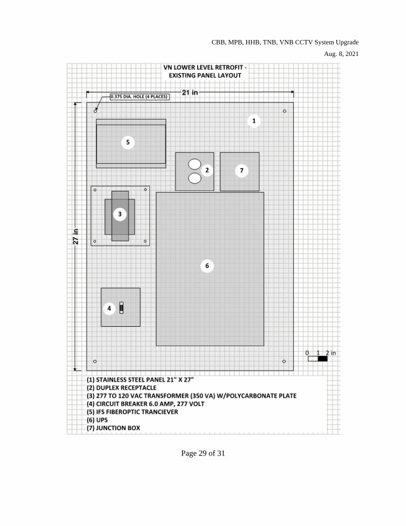
Q7 VN Lower Level Retrofit Cabinet Layout Drawing. Item # 1 on the Cabinet layout "stainless steel panel 2lx27 (Existing to remain)" indicates that the existing back panel will be reused to mount the new equipment. (Question 1) Please confirm if contractor should procure a new back panels for the purpose of mounting, wiring, and testing equipment during DAT & FAT testing?
A7. For the VN Lower Level Retrofit Cabinet, disregard "Existing to Remain" for the back Panel, transformer, circuit breaker and receptacle. Contractor shall furnish and test new back panels, fully populated and wired with all new components, including new transformer, new circuit breaker and new receptacle. The existing back panels and all existing internal components are to be removed by TBTA forces from the existing VN LL Retrofit cabinet shells
and replaced with the new fully populated back panels furnished by the Contractor. Please see attached revised Specifications dated August 8, 2021
for the VN LL Retrofit Cabinet Layout in Section 2.02.
Q8. Please confirm if Contractor should provide CA T-6 cables for CCTV cameras connections to the retrofit cabinets?
21-ITS-2983 Addendum #2
AS.
Q9.
A9.
The CAT 6 cables between the VN LL Retrofit Cabinets and the CCTV cameras will be provided by TBT A. Please see attached revised Specifications dated August 8, 2021, section 2.02, B, 11, section 2.02, G,2, and Section 3.03.
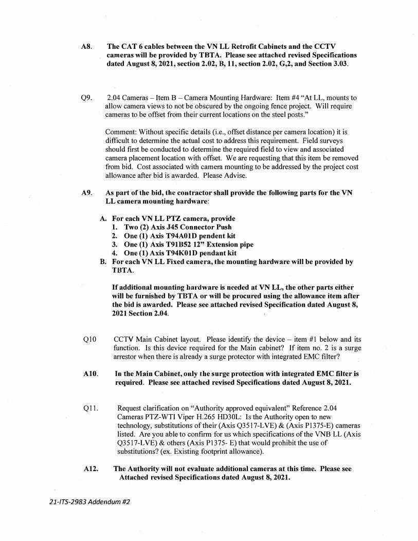
2.04 Cameras -Item B -Camera Mounting Hardware: Item #4 "At LL, mounts to allow camera views to not be obscured by the ongoing fence project. Will require cameras to be offset from their current locations on the steel posts."
Comment: Without specific details (i.e., offset distance per camera location) it is difficult to determine the actual cost to address this requirement. Field surveys should first be conducted to determine the required field to view and associated camera placement location with offset. We are requesting that this item be removed from bid. Cost associated with camera mounting to be addressed by the project cost allowance after bid is awarded. Please Advise.
As part of the bid, the contractor shall provide the following parts for the VN LL camera mounting hardware:
A. For each VN LL PTZ camera, provide1. Two (2) Axis J45 Connector Push
2. One (1) Axis T94A01D pendent kit3. One (1) Axis T91B52 12" Extension pipe
4. One (1) Axis T94K01D pendant kitB. For each VN LL Fixed camera, the mounting hardware will be provided by
TBTA.
If additional mounting hardware is needed at VN LL, the other parts either will be furnished by TBTA or will be procured using the allowance item after
the bid is awarded. Please see attached revised Specification dated August 8,
2021 Section 2.04.
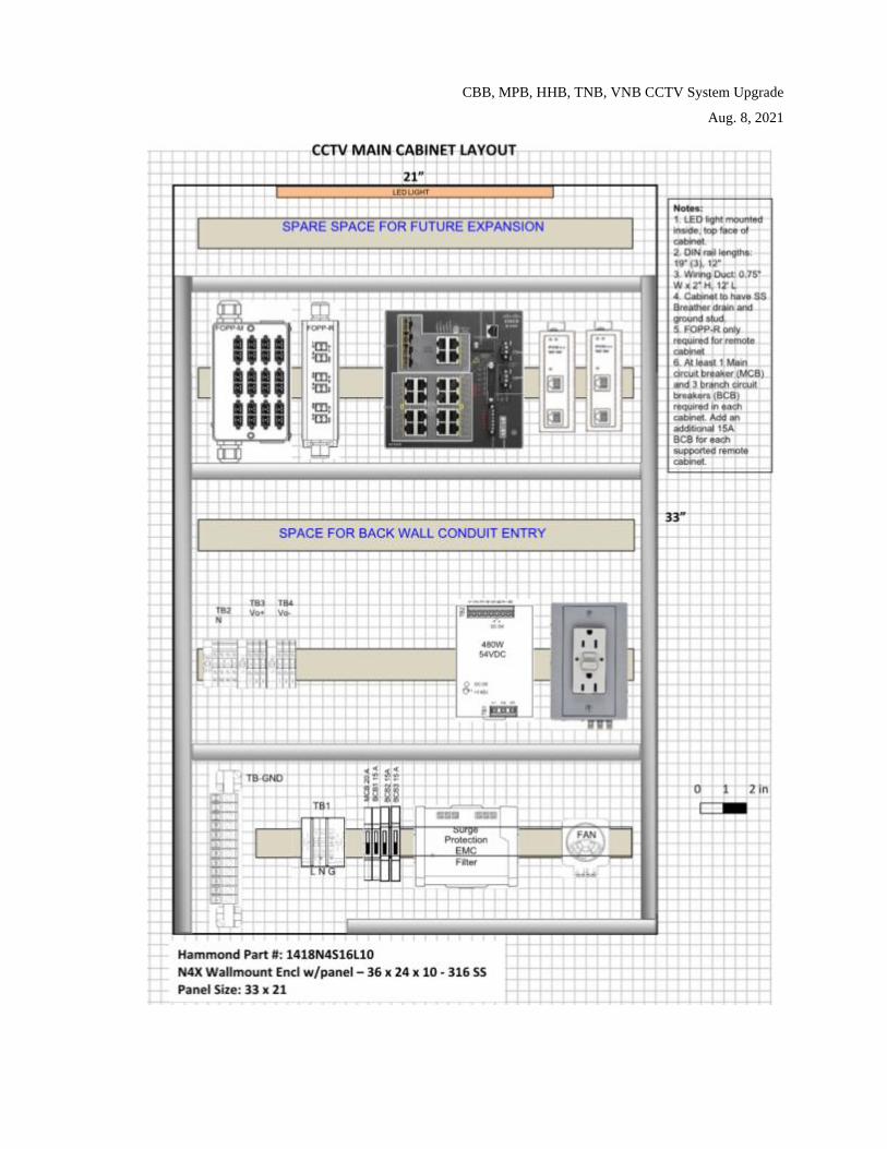
QI 0 CCTV Main Cabinet layout. Please identify the device -item # 1 below and its function. Is this device required for the Main cabinet? If item no. 2 is a surge arrestor when there is already a surge protector with integrated EMC filter?
AlO. In the Main Cabinet, only the surge protection with integrated EMC filter is
required. Please see attached revised Specifications dated August 8, 2021.
Q 11. Request clarification on "Authority approved equivalent" Reference 2.04 Cameras PTZ-WTI Viper H.265 HD30L: Is the Authority open to new technology, substitutions of their (Axis Q3517-LVE) & (Axis P1375-E) cameras listed. Are you able to confirm for us which specifications of the VNB LL (Axis Q35 l 7-LVE) & others (Axis P1375- E) that would prohibit the use of substitutions? ( ex. Existing footprint allowance).
A12. The Authority will not evaluate additional cameras at this time. Please see Attached revised Specifications dated August 8, 2021.
21-ITS-2983 Addendum #2

CBB, MPB, HHB, TNB, VNB CCTV System Upgrade
Aug. 8, 2021
Page 1 of 31
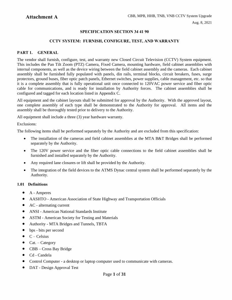
SPECIFICATION SECTION 34 41 90
CCTV SYSTEM: FURNISH, CONFIGURE, TEST, AND WARRANTY
PART 1. GENERAL
The vendor shall furnish, configure, test, and warranty new Closed Circuit Television (CCTV) System equipment.
This includes the Pan Tilt Zoom (PTZ) Camera, Fixed Camera, mounting hardware, field cabinet assemblies with
internal components, as well as the device wiring between the field cabinet assembly and the cameras. Each cabinet
assembly shall be furnished fully populated with panels, din rails, terminal blocks, circuit breakers, fuses, surge
protectors, ground buses, fiber optic patch panels, Ethernet switches, power supplies, cable management, etc. so that
it is a complete assembly that is fully operational unit once connected to 120VAC power service and fiber optic
cable for communications, and is ready for installation by Authority forces. The cabinet assemblies shall be
configured and tagged for each location listed in Appendix C.
All equipment and the cabinet layouts shall be submitted for approval by the Authority. With the approved layout,
one complete assembly of each type shall be demonstrated to the Authority for approval. All items and the
assembly shall be thoroughly tested prior to delivery to the Authority.
All equipment shall include a three (3) year hardware warranty.
Exclusions:
The following items shall be performed separately by the Authority and are excluded from this specification:
• The installation of the cameras and field cabinet assemblies at the MTA B&T Bridges shall be performed
separately by the Authority.
• The 120V power service and the fiber optic cable connections to the field cabinet assemblies shall be
furnished and installed separately by the Authority.
• Any required lane closures or lift shall be provided by the Authority.
• The integration of the field devices to the ATMS Dynac central system shall be performed separately by the
Authority.
1.01 Definitions
• A - Amperes
• AASHTO - American Association of State Highway and Transportation Officials
• AC - alternating current
• ANSI - American National Standards Institute
• ASTM - American Society for Testing and Materials
• Authority - MTA Bridges and Tunnels, TBTA
• bps - bits per second
• C – Celsius
• Cat. – Category
• CBB – Cross Bay Bridge
• Cd - Candela
• Control Computer - a desktop or laptop computer used to communicate with cameras.
• DAT - Design Approval Test
Attachment A

CBB, MPB, HHB, TNB, VNB CCTV System Upgrade
Aug. 8, 2021
Page 2 of 31
• DC - direct current
• DCS – device configuration software (provided by device manufacturers)
• ECP – MTA B&T’s Engineering and Construction Procedures
• EIA - Electronics Industry Alliance
• F - Fahrenheit
• FAT – Factory Acceptance Test
• FCC - Federal Communications Commission
• GUI - graphical user interface
• HHB – Henry Hudson Bridge
• Hz - Hertz or cycles per second
• IEC – International Electrotechnical Commission
• IEEE - Institute of Electrical and Electronic Engineers
• IP – Ingress Protection
• IP – Internet Protocol
• ISO - International Organization for Standardization
• ITS - Intelligent Transportation System
• LED - Light Emitting Diode
• LL – Lower Level
• MP – Megapixels
• MPB – Marine Parkway Bridge
• NEC - National Electric Code
• NEMA - National Electrical Manufacturers Association
• NTCIP - National Transportation Communications for ITS Protocol
• Object - An NTCIP term referring to an element of data in a NTCIP-compatible device that can be
manipulated to control or monitor the device
• ONVIF - Open Network Video Interface Forum
• Operator - Person using a computer to control or monitor devices
• OSHA - Occupational Safety and Health Administration
• PDU - Power Distribution Unit
• PDP – Power Distribution Panel
• PoE – Power over Ethernet
• PTZ – Pan Tilt Zoom
• RMA – Return Merchandise Authorization
• SAT – Stand Alone Test
• SFP – small form factor pluggable
• SNMP - Simple Network Management Protocol
• SS – Stainless Steel
• STMF - Simple Transportation Management Framework
• TCP: Transmission Control Protocol
CBB, MPB, HHB, TNB, VNB CCTV System Upgrade
Aug. 8, 2021
Page 3 of 31
• TNB – Throgs Neck Bridge
• UDP - User Datagram Protocol
• UL - Underwriters Laboratories
• μs – microsecond
• V – volt
• VN / VNB – Verrazano Narrows Bridge
• W – watt
1.02 References
A. AASHTO Standard Specifications for Structural Support for Highway Signs, Luminaires and Traffic
Signals
B. ANSI Z535.4: Product Safety Signs and Labels
C. IEEE 802.3af/at/bt: Standards for PoE Type 1, Type 2, Type 3, and Type 4
D. Moving Picture Experts Group: H.264
E. NEMA TS 2-2016: Traffic Controller Assemblies with NTCIP Requirements Version 03.07; Section 2
Environmental Requirements
F. ONVIF Profile S Specification
G. NEMA 250-2014 Enclosures for Electrical Equipment (1000 Volts Maximum): Type 4x
H. NTCIP 1205 v01 Amendment 1: Object Definitions for Closed Circuit Television (CCTV) Camera
Control
I. FCC Rule 15, Part B: Rules and Regulations for Unintentional Radiators
J. FHWA MUTCD 2009: Federal Highway Administration, Manual of Uniform Traffic Control Devices,
2009 Edition
K. IEC 60529: Degrees of Protection Provided by Enclosures (IP Code)
L. IEC 60068-2-6: Environmental testing – Part 2-6: Tests – Vibration (sinusoidal)
M. IEC 60068-2-27: Environmental testing – Part 2-27: Tests – Shock
N. IEC 62262: Degree of protection provided by enclosures for electrical equipment against external
mechanical impacts (IK code): IK10
O. IEEE C62.41.1: Guide on the Surge Environment in Low Voltage (1000 V and less) AC Power Circuits
P. IEEE C62.41.2: Recommended Practice on Characteristic of Surges in Low Voltage (1000 V and less)
AC Power Circuits
Q. IEEE C62.42.45: Recommended Practice on Surge Testing for Equipment Connected to Low Voltage
(1000V and less) AC Power Circuits
R. NEMA Standards Publication 250: Enclosures for Electrical Equipment (1000 V maximum)
S. UL 50: Enclosures for Electrical Equipment

CBB, MPB, HHB, TNB, VNB CCTV System Upgrade
Aug. 8, 2021
Page 4 of 31
T. UL 1449: Surge Protection Devices, Third Edition
1.03 Submittals
A. With their bid, Vendor shall sign and return the Qualifications Statement provided in Section 1.04 to
certify they fulfill the qualification requirements listed.
B. With their bid, the Vendor shall submit the following:
1. Proof of compliance with the qualifications listed in Section 1.04 including a list of installations with
agency names, system names, cabinet and camera type and quantity, commissioning date, contact
person names, addresses and telephone numbers of operating personnel who can be contacted
regarding the installations. Resume of proposed Project Manager and addresses and telephone
numbers of references. Address of cabinet assembly shop.
C. Within thirty days of contract award the Vendor shall submit an electronic copy of the following:
1. Product data catalog cut sheets, specifications, and installation and testing procedures for major
components including cabinet enclosures, cameras with software and related components, surge
protection devices, circuit breakers, Ethernet switch, SFP modules, fiber optic patch panel, and patch
cords.
2. Shop drawings for one (1) assembled cabinet of each type, including layouts of all internal
components, and wiring diagrams.
3. Site riser diagrams for each cabinet type, showing all cabling between the field cabinets and the
cameras.
D. Test Procedures – See “Testing” Section.
E. Training Materials – See “Training” Section.
CBB, MPB, HHB, TNB, VNB CCTV System Upgrade
Aug. 8, 2021
Page 5 of 31
1.04 Vendor Qualifications
A. The Vendor shall meet the requirements listed in the Qualifications Statement below.
Qualifications Statement
1. Vendor shall have been in business in North America for a minimum of five (5) years prior to the bid date,
and Vendor’s cabinet assembly facility shall be no more than 75 miles away from NYC.
2. Vendor shall have delivered field equipment cabinet assemblies for a minimum of five (5) Roadway CCTV
projects, for at least two (2) different public sector roadway agencies in New York, New Jersey, or
Connecticut. The field equipment cabinets delivered have been operating successfully for at least two (2)
years.
3. Vendor shall provide a qualified Project Manager for the duration of the project. Project Manager shall
have experience in implementing a minimum of five (5) Roadway CCTV projects for two (2) Public
agencies in New York, New Jersey, or Connecticut.
4. Vendor shall have experience in conducting onsite testing of cameras and field cabinets on roadways.
5. Vendor shall have experience in configuring Cisco switches, and the vendor shall utilize staff with Cisco
certification for this task.
6. Vendor shall have experience in IP camera configuration for traffic monitoring.
7. Vendor shall have experience in providing IP based camera configuration training to Public Transportation
Agency internal work forces within in the past five (5) years.

CBB, MPB, HHB, TNB, VNB CCTV System Upgrade
Aug. 8, 2021
Page 6 of 31
PART 2. PRODUCTS
2.01 Cabinet Assemblies
A. The Vendor shall furnish complete, populated, tested cabinet assemblies that are customized by location,
to the Authority for installation by Authority forces.
B. Cabinet enclosure shall meet the following requirements:
1. NEMA 4X 316 SS
2. Unpainted with smooth brushed finish.
3. Single full-size front door with the door opening flanged on all sides. Catch to hold the door open until
released.
4. 3-point latching mechanism with keyed lock and handle or Hasp and staple for padlocking the door.
The Authority will specify the keying of the lock. One keyed lock and two keys shall be provided with
each cabinet.
5. Tamperproof door hinges
6. All required mounting hardware shall be provided with each cabinet.
7. Clear plastic data pocket mounted to the inside of the door for the storage of documentation.
8. Internal wall stiffeners as required for pole mounting.
9. NEMA 4X SS breather drain with castellated lock nut.
10. Designed to support panel mounted equipment, rack mounting is not required.
11. Internal panels, DIN rails, and shelves as required to mount all equipment.
12. Provisions for conduit entry, gutter space for cable bends, cable management on panel as needed.
13. Size as required to mount all cabinet equipment plus a minimum of 10% spare space.
a. Spare space measured as contiguous vertical space on the back panel that is completely unoccupied
and not used for cable management or panel mounting, or otherwise occupied as gutter space at
conduit entry points.
C. Shall include power distribution components:
1. Terminal blocks to land incoming power cables.
2. Circuit breaker assembly including main circuit breaker. Circuit breakers approved and listed by UL.
3. AC power line surge protectors shall be installed between the load side of the input circuit breaker and
ground.
a. Nominal Line Voltage: Rated for the electrical service.
b. Modes of Protection: Main Neutral to Ground, Main Line to Ground, Line to Line.
c. Meets UL1449.
4. Ground bus (to be kept separate from the neutral in the cabinet).
5. Neutral bus.
CBB, MPB, HHB, TNB, VNB CCTV System Upgrade
Aug. 8, 2021
Page 7 of 31
6. DC power supplies.
7. Low Voltage Power, communication and control conductors surge protection on all copper cables
entering the cabinet.
D. Shall include SS pole mounting brackets and SS bands to mount at locations where required.
E. Electrical Identification
1. Provide wiring diagrams specific to each cabinet and install in a re-enterable plastic sleeve.
2. Include external cabinet labels suitable for the service conditions. Coordinate tags with the Authority.
3. Include internal device and wiring labels that are suitable for the service conditions and that
correspond with the wiring diagrams.
4. Safety labels in accordance with OSHA, NEMA and NEC requirements shall be used to indicate
potential dangerous or hazardous situations. The contents of the labels shall be in accordance with the
ANSI Z535.4 standard, Product Safety Signs and Labels.
F. Ethernet Switch
1. Cisco Industrial grade shall be CISCO IE-4000-4GS8GP4G-E at all locations except for locations
designated as “Remote Cabinets” which shall be CISCO IE-3200-8P2S-E (CISCO IE-2000
replacement)– no exceptions.
2. Cisco Rugged SFP modules shall be CISCO GLC-LX-SM-RGD (1000BASE-LX/LH) or approved
equivalent.
3. Power Supply.
4. Mount on DIN rail within cabinet.
5. Wiring internal to cabinet including all required fiber patch cords to FOPP and copper patch cords to
equipment. Patch cords shall be suitable for the service conditions.
G. Fiber Optic Patch Panel
1. Furnish 48 fiber and 12 fiber patch panels.
2. Can support the splice and termination of one incoming 12 strand bulk fiber cable.
3. LC connectors.
4. Furnish factory connectorized pigtails, splice tray, sleeves, and cable management for future splice to
bulk cable by the Authority.
2.02 VN LL Cabinet Retrofit
A. The Vendor shall furnish configured and tested assemblies that can be readily installed into existing VN
LL cabinet shells. Authority forces will remove the existing backpanels and components in these shells
and replace them with the retrofit assemblies provided by the Vendor. The assemblies are to be
customized by location, tested, and delivered to the Authority.
B. Vendor-provided retrofit assemblies shall include components that meet the requirements listed in Section
2.01 and as described below. At a minimum these assemblies shall include:
1. Stainless Steel Back Panel
2. Primary side main over current protection device – 1 pole, 3A, 277VAC, UL listed
CBB, MPB, HHB, TNB, VNB CCTV System Upgrade
Aug. 8, 2021
Page 8 of 31
3. Step down transformer – single phase, 277VAC primary, 120VAC secondary, 350VA, UL listed
4. Polycarbonate plate over transformer and terminals
5. NEMA 5-15R Receptacle, UL listed
6. Ground Bus
7. 2 Port ST to ST fiber optic outlet (mounted to back panel)
8. ST to LC fiber optic patch cords
9. Ethernet Switch, Power Supply, SFP Modules
10. PoE Injectors
11. Surge Suppressors on each Cat 6 cable from cameras (these cables are provided by TBTA)
12. Surge Suppressor on AC Power feeding the cabinet
13. Din Rail and mounting hardware
14. Terminal blocks and wiring between all components provided
15. Electrical Identification (Tags)
16. Wiring Diagrams
2.03 VN LL Cabinet Assembly
A. The Vendor shall furnish complete, populated, tested cabinet assemblies that are customized by location,
to the Authority for installation by Authority forces.
B. Cabinets shall meet the requirements of Section 2.01.
2.04 Cameras
A. The acceptable models are:
• For VNB LL:
o Fixed – Axis Q3517-LVE – no substitutions
o PTZ – Axis Q6155-E – no substitutions
• For locations other than VNB LL:
o Fixed – Axis P1375-E – no substitutions
o PTZ –WTI Viper H.265 HD30L – no substitutions.
B. Camera Mounting Hardware
1. Furnish hardware for pole mount, wall mount, sign gantry mount, or structural steel mount as required
for the individual locations identified.
2. Weather-resistant mounts suitable for the service conditions. This includes a marine environment with
vibrations due to traffic and wind.
3. All ancillary mounting hardware such as struts, U-bolts, straps, bolts, washer, and nuts shall be
stainless steel.
CBB, MPB, HHB, TNB, VNB CCTV System Upgrade
Aug. 8, 2021
Page 9 of 31
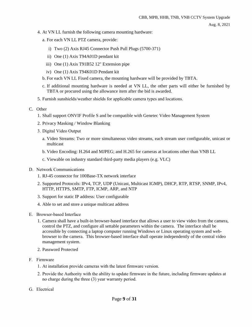
4. At VN LL furnish the following camera mounting hardware:
a. For each VN LL PTZ camera, provide:
i) Two (2) Axis RJ45 Connector Push Pull Plugs (5700-371)
ii) One (1) Axis T94A01D pendant kit
iii) One (1) Axis T91B52 12" Extension pipe
iv) One (1) Axis T94K01D Pendant kit
b. For each VN LL Fixed camera, the mounting hardware will be provided by TBTA.
c. If additional mounting hardware is needed at VN LL, the other parts will either be furnished by
TBTA or procured using the allowance item after the bid is awarded.
5. Furnish sunshields/weather shields for applicable camera types and locations.
C. Other
1. Shall support ONVIF Profile S and be compatible with Genetec Video Management System
2. Privacy Masking / Window Blanking
3. Digital Video Output
a. Video Streams: Two or more simultaneous video streams, each stream user configurable, unicast or
multicast
b. Video Encoding: H.264 and MJPEG; and H.265 for cameras at locations other than VNB LL
c. Viewable on industry standard third-party media players (e.g. VLC)
D. Network Communications
1. RJ-45 connector for 100Base-TX network interface
2. Supported Protocols: IPv4, TCP, UDP (Unicast, Multicast IGMP), DHCP, RTP, RTSP, SNMP, IPv4,
HTTP, HTTPS, SMTP, FTP, ICMP, ARP, and NTP
3. Support for static IP address: User configurable
4. Able to set and store a unique multicast address
E. Browser-based Interface
1. Camera shall have a built-in browser-based interface that allows a user to view video from the camera,
control the PTZ, and configure all settable parameters within the camera. The interface shall be
accessible by connecting a laptop computer running Windows or Linux operating system and web-
browser to the camera. This browser-based interface shall operate independently of the central video
management system.
2. Password Protected
F. Firmware
1. At installation provide cameras with the latest firmware version.
2. Provide the Authority with the ability to update firmware in the future, including firmware updates at
no charge during the three (3) year warranty period.
G. Electrical

CBB, MPB, HHB, TNB, VNB CCTV System Upgrade
Aug. 8, 2021
Page 10 of 31
1. PoE Type 1 (IEEE 802.3af) thru PoE Type 4 (IEEE 802.3bt)
2. Cables between the cameras and field cabinet shall be of sufficient length, shall be outdoor rated Cat.
6, and shall be furnished and installed by TBTA.
H. Miscellaneous
1. Furnish and install surge suppression devices where the Cat. 6 camera cables enter the field cabinet.
Devices shall be suitable for the application and the service conditions.
2. All materials shall be new, unless otherwise indicated in this specification.
3. All incidental parts which are necessary to complete the installation but are not specified herein, shall
be suitable for the outdoor service conditions, compatible with the camera model furnished, and shall
be provided as necessary to complete a properly operating system.
2.05 Device Configuration Software
A. General
If all camera configuration parameters that are not available through a web interface to the camera, then
furnish the DCS. The Device Configuration Software (DCS) is the software provided by the
manufacturers of the Cameras to monitor, control, and configure their respective equipment. The Cameras
will connect to the DCS for configuration and testing by the Vendor, and later by the Authority for their
use.
The DCS software licenses shall be furnished by the bidder for use by the Authority.
The future integration of the Cameras to the Authority’s existing Dynac ATMS will be performed by the
Authority.
B. DCS Hardware
The DCS hardware (expected to be a laptop or tablet) shall be furnished by the Vendor for their use during
configuration and testing.
The DCS hardware shall be furnished by the Authority for their use after devices are installed at the Bridges
for their use during testing.
C. DCS Software
The DCS software shall:
1. Operate on desktop, server, and laptop computers and run the latest version of the Microsoft
Windows (minimum Windows 10), or if the software runs from a MTA B&T central server it should
be compatible with Windows 16 OS.
2. Provide a user-friendly multi-color graphical user interface.
3. Support communications with the Cameras via IP over Ethernet.
4. Monitor, configure, or control Cameras both remotely from a central location, and locally at the
cabinet site when needed.
5. Be accompanied by an easy-to-use software installation routine.
6. Include an operation manual that includes detailed instructions for installing, configuring, and using
the software.

CBB, MPB, HHB, TNB, VNB CCTV System Upgrade
Aug. 8, 2021
Page 11 of 31
7. Contain an on-line help system that includes documentation for the screens and dialog boxes present in
the software.
D. Software Security
The DCS software shall support the creation of user IDs and passwords.
Before an operator can use the DCS, the software shall request a “username” and user “password”. If the
correct username and password are not provided, access shall be declined.
E. System Configuration
1. The DCS software shall allow system administrators and other users with correct security access, to
configure many system parameters and functions including the configurable settings within the field
devices.
F. Software Use and Reproduction Rights
The Vendor shall provide three (3) DCS licenses. Copies of the DCS shall be provided to the Authority
within thirty (30) days of the first SAT Any DCS software upgrades or patches released shall be made
available to the Authority at no cost during the Contract Period.
PART 3. EXECUTION
3.01 Safety
Vendor shall meet or exceed OSHA safety requirements and ensure all subcontractors or persons working
with them follow this same requirement. Vendor shall adhere to the MTA B&T ECPs. Contractor shall
adhere to all applicable city, state, and local codes.
3.02 Shop Drawings
Vendor submit cut sheets for all equipment to be furnished. Vendor shall submit cabinet layouts for each
cabinet type (Main, Remote, VN LL Retrofit, VN LL Replacement) prior to the DAT. After approval of the
DAT, the Vendor shall layout the cabinets specific to each location and to support the internal equipment to
be furnished and submit as shop drawings.
The cabinet layouts, wiring diagrams, and riser diagram shall adhere to all applicable city, state, and local
codes. Electrical and communications infrastructure design shall conform to the latest version of NFPA 70 -
National Electrical Code (NEC). Information Technology (IT) related items shall be in accordance with
MTA B&T IT requirements.
Submittal shall be in accordance with MTA B&T Engineering and Construction Procedures (ECPs).
3.03 Manufacturer Quality Certifications
For each major component, submit Quality Certifications from the manufacturer to document that each unit
was quality tested prior to shipment. At a minimum, submit Quality Certifications for the following
components:
• Cabinet Enclosures
• Cameras
• Ethernet Switches, power supplies, SFP modules
• AC Surge Protectors
• Fiber Optic Patch Panels and Patch Cords
• Cat 6 cable Surge Protectors
CBB, MPB, HHB, TNB, VNB CCTV System Upgrade
Aug. 8, 2021
Page 12 of 31
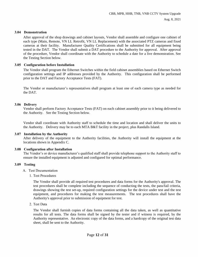
3.04 Demonstration
After approval of the shop drawings and cabinet layouts, Vendor shall assemble and configure one cabinet of
each type (Main, Remote, VN LL Retrofit, VN LL Replacement) with the associated PTZ cameras and fixed
cameras at their facility. Manufacturer Quality Certifications shall be submitted for all equipment being
tested in the DAT. The Vendor shall submit a DAT procedure to the Authority for approval. After approval
of the procedure, Vendor shall coordinate with the Authority to schedule a date for a live demonstration. See
the Testing Section below.
3.05 Configuration before Installation
The Vendor shall program the Ethernet Switches within the field cabinet assemblies based on Ethernet Switch
configuration settings and IP addresses provided by the Authority. This configuration shall be performed
prior to the DAT and Factory Acceptance Tests (FAT).
The Vendor or manufacturer’s representatives shall program at least one of each camera type as needed for
the DAT.
3.06 Delivery
Vendor shall perform Factory Acceptance Tests (FAT) on each cabinet assembly prior to it being delivered to
the Authority. See the Testing Section below.
Vendor shall coordinate with Authority staff to schedule the time and location and shall deliver the units to
the Authority. Delivery may be to each MTA B&T facility in the project, plus Randalls Island.
3.07 Installation by the Authority
After delivery of the equipment to the Authority facilities, the Authority will install the equipment at the
locations shown in Appendix C.
3.08 Configuration after Installation
The Vendor’s or device manufacturer’s qualified staff shall provide telephone support to the Authority staff to
ensure the installed equipment is adjusted and configured for optimal performance.
3.09 Testing
A. Test Documentation
1. Test Procedures
The Vendor shall provide all required test procedures and data forms for the Authority's approval. The
test procedures shall be complete including the sequence of conducting the tests, the pass/fail criteria,
drawings showing the test set-up, required configuration settings for the device under test and the test
equipment, and procedures for making the test measurements. The test procedures shall have the
Authority's approval prior to submission of equipment for test.
2. Test Data
The Vendor shall furnish copies of data forms containing all the data taken, as well as quantitative
results for all tests. The data forms shall be signed by the tester and if witness is required, by the
Authority representative. An electronic copy of the data forms, and a hardcopy of the original test data
sheet, shall be sent to the Authority.

CBB, MPB, HHB, TNB, VNB CCTV System Upgrade
Aug. 8, 2021
Page 13 of 31
B. Design Approval Tests (DAT)
The DAT shall be performed by the Vendor at their facility on one (1) complete cabinet assembly of each
type, and at least one (1) camera of each type. DAT shall be performed in the presence of Authority
personnel or its representative. The following tests shall be performed as part of the DAT:
1. Examination of Product: The equipment shall be examined to determine compliance with these
Specifications and with the approved shop drawings and cabinet layout.
a. Workmanship is to be a high level of quality.
b. All cabinets, enclosures, and attachments shall be structurally sound and in accordance with industry
standards.
c. Wiring shall be neatly managed within the cabinets.
d. All cabinets and wiring shall be labeled and organized.
e. Labels placed on hardware shall correspond with labels in documentation submitted.
2. Water Test: A water spray test shall be performed on the cabinet enclosure. The test shall be
performed as follows: Using a garden hose with water flowing at a minimum rate of one-half gallon
per minute, direct the water at the housing from above at an angle of 45 degrees from horizontal for ten
minutes. Perform this test with the hose directed from the front, each side and back of the sign
enclosure and controller cabinet. Verify at the completion of the test that the inside of the housing and
cabinet are dry.
3. Wiring: The wiring shall be checked to determine conformance with these Specifications, including.
a. Grounding and Bonding
b. 120VAC Power Distribution and Overcurrent Protection
4. Operational Test: Each unit shall be operated long enough to permit equipment temperature
stabilization, and to check and record an adequate number of performance characteristics to ensure
compliance with these Specifications. The test shall:
a. Exercise all functions related to operation of the cameras.
b. Simulate error and fault conditions to demonstrate redundancy, diagnostics, and reporting.
c. Demonstrate local operation
d. Simulate remote operation using a laptop connected to the local Ethernet switch.
5. Demonstration that the DCS software furnished as part of this item meets the specified requirements.
The equipment shall have operated normally during and after the performance of these tests. If the
unit fails the DAT, the design fault shall be corrected, and all DAT shall be repeated. All deliverable
units shall be modified, without additional cost to Authority, to include design changes required to
pass the DAT.
Following approval of the DAT results in writing by the Authority, Vendor may begin procurement of the
remaining units and assembly of the remaining cabinets.
C. Factory Acceptance Test (FAT)
The Vendor shall conduct a FAT on each assembled cabinet prior to shipping to the Authority. The FAT
shall be performed on each unit in accordance with the approved procedure. FAT procedures shall be

CBB, MPB, HHB, TNB, VNB CCTV System Upgrade
Aug. 8, 2021
Page 14 of 31
similar to those of the approved DAT. Documentation of these tests shall be submitted to the Authority
with the units.
If a device has been modified as a result of a FAT failure, a report shall be prepared and delivered to the
Authority prior to shipment of the equipment. The report shall describe the failure and corrective action
taken. If a failure pattern, as defined by the Authority, develops, the Authority may direct that design and
construction modifications be made to all units without additional cost to the Authority or extension of the
contract period. The Vendor shall not ship without successful completion of FAT.
D. Stand Alone Test (SAT)
Following installation and configuration, the Vendor shall perform a SAT at each cabinet location, to be
witnessed by Authority forces. Devices shall be configured for the SAT using IP addresses supplied by
the Authority. The SAT shall be performed in accordance with the approved procedure. This test shall
include a demonstration of operation of the device locally on an Authority computer. The SAT does not
require connection to the Authority WAN.
Satisfactory completion of the SAT will be the basis for acceptance of the equipment.
In the event of a failure of a device or a failure of the SAT, the Vendor shall cover the cost of return
shipping, shall correct the failure, shall cover the cost of shipping the new or repaired unit to the
Authority, and the device will be retested.
If a unit has been modified because of a Test failure, a report shall be prepared and delivered to the
Authority prior to retesting of the equipment. The report shall describe the nature of the failure and
corrective action taken. If a failure pattern, as defined by the Authority, develops, the Authority may
direct that design and construction modifications be made to all units without additional cost to the
Authority.
E. Operations and Maintenance Manuals
After completion of testing, deliver three hard copies and one electronic copy of Operations and
Maintenance (O&M) Manuals for all devices and the cabinet assembly to the Authority. O&M Manuals
shall include both the manufacturer provided generic information, as well as the specific location and
configuration information for all devices furnished as part of this project.
3.10 Training
After successfully completing SATs for all units in the project, the Vendor or Manufacturer shall provide two
types of on-site training. Prior to the training sessions, submit qualifications of trainers, agendas and
materials to the Authority for review and approval. Coordinate schedules and locations with the Authority.
A. Maintenance Training
This training shall include a total or four (4) half -day on-site training sessions. Two (2) of the sessions shall
performed on one (1) day at one Authority facility. The other two (2) sessions shall be performed on one (1)
day at a different Authority facility. Train MTA B&T Maintenance staff in the use of the cameras. Include
the built-in browser user-interface, DCS if applicable, monitoring and control of cameras, and reporting.
B. System Administrator Training
This session shall include one (1) full day of training on-site at one (1) MTA B&T facility or a remote session
with Authority approval. Train MTA B&T technical staff in the administration of the DCS if applicable,
camera hardware and software. Include system installation and configuration, software updates, backup and
restore, network configuration, security and user-access, built-in browser user-interface, diagnostics,
calibration, reporting, and troubleshooting.

CBB, MPB, HHB, TNB, VNB CCTV System Upgrade
Aug. 8, 2021
Page 15 of 31
3.11 Support Services
A. Telephone Support
1. Following the approval of all SATs, the Vendor and Manufacturers shall provide one year of
telephone support. Provide the Authority with a telephone number and email address for the
Vendor point of contact. A qualified technician shall respond to all telephone calls and requests
for information within one (1) hour during normal working hours.
B. On-site Support
2. Following the approval of all SATs, the Vendor or Manufacturers shall provide up to ten (10) days
of on-site support. Each day shall include seven (7) hours at the Authority facility. The
Technician shall assist the Authority in the troubleshooting and optimizing the performance of the
installed equipment. Work is to be performed at an Authority facility.
3. The Installation Support period shall be within 12 months of the delivery of the approved hardware
to the Authority. Coordinate schedule for on-site support with the Authority.
3.12 Warranty
1. The Vendor shall provide a three (3) year warranty as part of their proposal.
2. Warranty shall include all hardware and software furnished under this Contract.
3. The Vendor shall include the cost of shipping, including Return Merchandise Authorization
(RMA), and the cost of shipping replacement parts to the Authority.
3.13 Spare Parts
Spare parts shall be of the approved make/model. Furnish one complete set of spare parts of the types and
quantities listed below:
Description Units Quantity
Main Cabinet Assembly (complete fully populated
cabinet assembly with all components including
power distribution, pole mounting hardware, labels
and tags, fiber optic patch panel and patch cords.)
EA 2
Remote Cabinet Assembly (complete fully
populated cabinet assembly with all components
including power distribution, pole mounting
hardware, labels and tags, fiber optic patch panel
and patch cords.)
EA 2
Main Cabinet Ethernet Switch including software
license, 2 SMOF SFP modules, and power supply
EA 2
Remote Cabinet Ethernet Switch including
software license, 2 SMOF SFP modules, and power
supply
EA 2
Fixed Camera EA 2

CBB, MPB, HHB, TNB, VNB CCTV System Upgrade
Aug. 8, 2021
Page 16 of 31
PTZ Camera EA 2
Camera Pole Mount EA 8
Fixed Camera Weather shield kit EA 4
VN LL PTZ camera EA 2
VN LL Fixed camera EA 2
VN LL Cabinet Retrofit assembly EA 2
VN LL Cabinet Replacement EA 2
After approval of all SATs, deliver Spare Parts to one (1) Authority facility. Coordinate delivery schedule
and location with the Authority.
3.14 Allowance for Field Change Requests
In this item an Allowance is set aside to provide for potential future field change requests. The scope of
work, schedule, and price for these requests shall be mutually agreed upon by the Vendor and the Authority
prior to starting work on them. No payment will be made for this item without prior formal agreement in
writing by both parties on the scope of work, schedule, and budget.
PART 4. MEASUREMENT AND PAYMENT
4.01 Method of Measurement
A. The Cabinet items are measured in units of Each (EA).
B. The Camera items are measured in units of Each (EA).
C. The Training item is measured in units of Lump Sum (LS).
D. The Support Services item is measured in units of Lump Sum (LS).
E. The Spare Parts item is measured in units of Lump Sum (LS).
F. The Allowance item’s measurement of work ordered by the Authority shall be set forth in the Scope of
work agreed upon by the parties.
4.02 Basis of Payment
A. The Cabinet items include all elements listed under Section 2.01, 2.02, and 2.03, including Submittals
listed under Section 1.03, Testing listed under Section 3.09, and Warranty listed under Section 3.12.
B. The Camera items include all elements listed under Section 2.04, including Submittals listed under
Section 1.03, Testing listed under Section 3.09, and Warranty listed under Section 3.12.
C. The Training item includes all elements listed under Section 3.10.
D. The Support Services item includes all elements listed under Section 3.11.
CBB, MPB, HHB, TNB, VNB CCTV System Upgrade
Aug. 8, 2021
Page 17 of 31
E. The Spare Parts item includes all elements listed under Section 3.13.
F. The Allowance item includes all elements listed under Section 3.14. An Allowance (AL) for the work
performed throughout the life of this project not to exceed $150,000 has been designated. This amount
will be drawn down as part of the monthly payment requisition for work performed under this item. If the
Allowance is not entirely utilized, the unused funds shall be credited to the Authority.
4.03 Progress Payments
A. For Cabinets and Cameras:
• 10% of all units on acceptance of shop drawings
• 30% of all units upon approval of DAT results
• 30% of each unit upon procurement and approval of FAT results for each unit
• 30% of each unit upon approval of the SAT for each unit.
B. For Training:
• 50% upon completion of the Maintenance Training
• 50% upon completion of the System Administrator Training
C. For Support Services:
• 100% upon completion of the 10 days of support, or the completion of the 12-month Support Services
period.
D. For Spare Parts:
• 100% upon delivery of the Spare Parts to the Authority facility.
E. For Contingency:
• 100% of the agreed upon price upon delivery of the agreed upon scope of services.
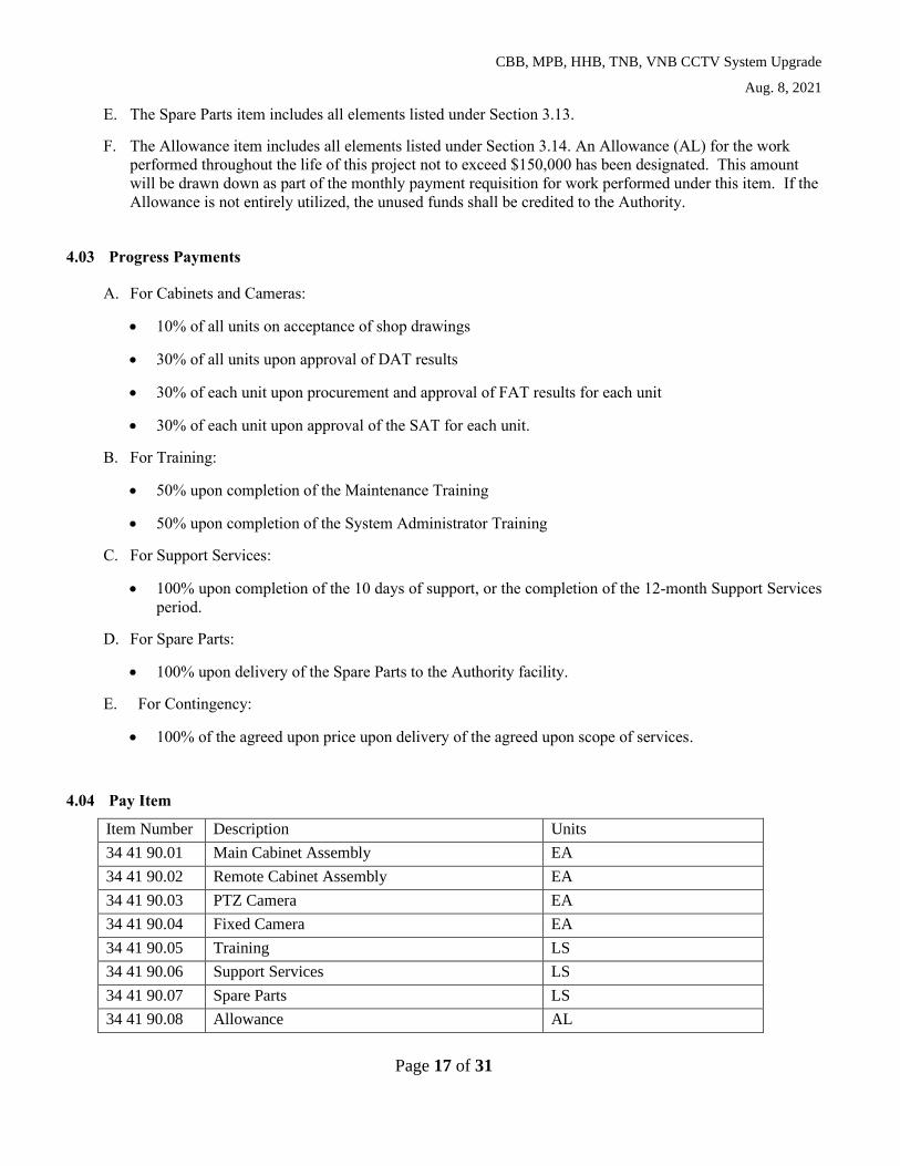
4.04 Pay Item
Item Number Description Units
34 41 90.01 Main Cabinet Assembly EA
34 41 90.02 Remote Cabinet Assembly EA
34 41 90.03 PTZ Camera EA
34 41 90.04 Fixed Camera EA
34 41 90.05 Training LS
34 41 90.06 Support Services LS
34 41 90.07 Spare Parts LS
34 41 90.08 Allowance AL

CBB, MPB, HHB, TNB, VNB CCTV System Upgrade
Aug. 8, 2021
Page 18 of 31
34 41 90.09 VN LL PTZ Camera EA
34 41 90.10 VN LL Fixed Camera EA
34 41 90.11 VN LL Cabinet Retrofit EA
34 41 90.12 VN LL Cabinet Replacement EA
END OF SECTION
CBB, MPB, HHB, TNB, VNB CCTV System Upgrade
Aug. 8, 2021
Page 19 of 31
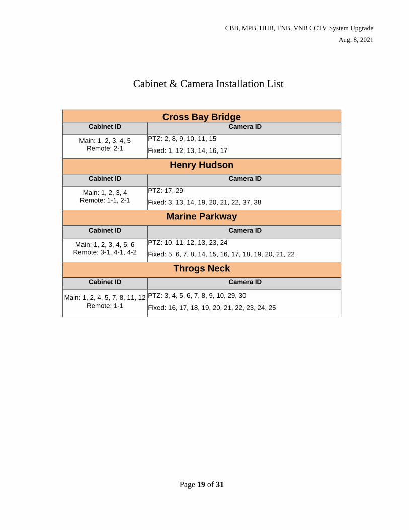
Cabinet & Camera Installation List
Cross Bay Bridge Cabinet ID Camera ID
Main: 1, 2, 3, 4, 5 Remote: 2-1
PTZ: 2, 8, 9, 10, 11, 15
Fixed: 1, 12, 13, 14, 16, 17
Henry Hudson
Cabinet ID Camera ID
Main: 1, 2, 3, 4 Remote: 1-1, 2-1
PTZ: 17, 29
Fixed: 3, 13, 14, 19, 20, 21, 22, 37, 38
Marine Parkway
Cabinet ID Camera ID
Main: 1, 2, 3, 4, 5, 6 Remote: 3-1, 4-1, 4-2
PTZ: 10, 11, 12, 13, 23, 24
Fixed: 5, 6, 7, 8, 14, 15, 16, 17, 18, 19, 20, 21, 22
Throgs Neck
Cabinet ID Camera ID
Main: 1, 2, 4, 5, 7, 8, 11, 12 Remote: 1-1
PTZ: 3, 4, 5, 6, 7, 8, 9, 10, 29, 30
Fixed: 16, 17, 18, 19, 20, 21, 22, 23, 24, 25

CBB, MPB, HHB, TNB, VNB CCTV System Upgrade
Aug. 8, 2021
Page 20 of 31
Verrazano-Narrows Bridge Lower Level
Cabinet ID Camera ID
Main: 16, 17
Security Cabinet: 1 to 15
PTZ: 24, 25, 18, 19, S10060 to S10074 (S10068 is existing PTZ-to remain)
Fixed: 56 A & B, 57 A & B, 58 A & B, 59 A & B, 60 A & B, 61 A & B, 62 A & B, 63 A & B, 64 A & B, 65 A & B, 66 A & B, 67 A & B, 68 A & B, 69 A & B, 70 A & B
Verrazano-Narrows Bridge Non-Lower Level
Cabinet ID Camera ID
Main:
VN-1, VN-2, VN-3, VN-5,
VN-4 (Exist. VN03 cabinet to remain),
VN-6 (Exist. VN03 cabinet to remain),
VN-17, VN-18, VN-20, VN-22,
VN-VMS1, (Exist. cabinet to remain)
VN-VMS2, (Exist. cabinet to remain)
VN-BKT-1, VN-BKT-2,
VN-SIT-1, VN-SIT-2
PTZ: 14, 26,16-1,16-2, 81, 82, 8, 84, 7, 51, 52, 39, 40
11, 41, 42, 53,12, 5, 79, GG29
Fixed: 30, 31, 32, 33, 34, 35, 36, 37, 77, 3, 80, 5A, 5B, 2, 6, 79A, 79B
CBB, MPB, HHB, TNB, VNB CCTV System Upgrade
Aug. 8, 2021
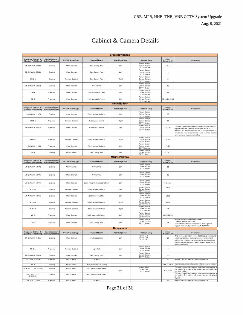
Page 21 of 31
Cabinet & Camera Details
Cross Bay Bridge
Proposed Cabinet ID (Existing Field Name)
Cabinet Location: Existing/Proposed
CCTV Cabinet Type Cabinet Mount Door Hinge Side Conduit Entry Direct
Cameras ID Comments
CB-1 (AW-36 CB01) Existing Main Cabinet Sign Gantry Post Left
Power: Bottom
Comm: Bottom CCTV: Bottom
1,8,17
CB-2 (AW-36 CB02) Existing Main Cabinet Sign Gantry Post Left
Power: Bottom
Comm: Bottom
CCTV: Bottom
9
CB-2-1 Existing Remote Cabinet Sign Gantry Post Right
Power: Bottom
Comm: Bottom
CCTV: Bottom
2
CB-3 (AW-36 CB03) Existing Main Cabinet CCTV Pole Left
Power: Bottom
Comm: Bottom
CCTV: Bottom
10
CB-4 Proposed Main Cabinet High Mast Light Tower Left
Power: Bottom
Comm: Bottom
CCTV: Bottom
11
CB-5 Proposed Main Cabinet High Mast Light Tower Left
Power: Bottom
Comm: Bottom
CCTV: Bottom
12,13,14,15,16
Henry Hudson
Proposed Cabinet ID (Existing Field Name)
Cabinet Location: Existing/Proposed
CCTV Cabinet Type Cabinet Mount Door Hinge Side Conduit Entry Direct
Cameras ID Comments
HH-1 (AW-36 HH05) Existing Main Cabinet Steel Support Column Left
Power: Bottom
Comm: Bottom
CCTV: Bottom
22
HH-1-1 Proposed Remote Cabinet Railing/strut mount Right
Power: Bottom
Comm: Bottom
CCTV: Bottom
37
HH-2 (AW-36 HH03) Proposed Main Cabinet Railing/strut mount Left
Power: Bottom
Comm: Bottom
CCTV: Bottom
19, 38 The existing cabinet contains a 144F FO patch panel
supporting other cabinets in the area. So as to
minimize the amount of work, the existing cabinet is to
remain and provide power and comm to a new cabinet
to be installed on adjacent railing
HH-2-1 Proposed Remote Cabinet Steel Support Column Right
Power: Bottom
Comm: Bottom
CCTV: Bottom
3, 20
HH-3 (AW-36 HH02) Proposed Main Cabinet Steel Support Column Left
Power: Bottom
Comm: Bottom
CCTV: Bottom
21,29
HH-4 Existing Main Cabinet Sign Gantry Post Left
Power: Bottom
Comm: Bottom
CCTV: Back 13,14, 17
Marine Parkway
Proposed Cabinet ID (Existing Field Name)
Cabinet Location: Existing/Proposed
CCTV Cabinet Type Cabinet Mount Door Hinge Side Conduit Entry Direct
Cameras ID Comments
MP-1 (AW-36 MP06) Existing Main Cabinet CCTV Pole Left
Power: Bottom
Comm: Bottom
CCTV: Bottom 11
MP-2 (AW-36 MP05) Existing Main Cabinet CCTV Pole Left
Power: Bottom
Comm: Bottom
CCTV: Bottom 10
MP-3 (AW-36 MP03) Existing Main Cabinet South Tower, below east walkway Left
Power: Bottom
Comm: Bottom
CCTV: Bottom 7, 8, 13, 17
MP-3-1 Existing Remote Cabinet Steel Support Column Left
Power: Bottom
Comm: Bottom
CCTV: Bottom
16,19
MP-4 (AW-36 MP01) Existing Main Cabinet North Tower roof top Left
Power: Bottom
Comm: Bottom
CCTV: Bottom 12,15
MP-4-1 Existing Remote Cabinet Steel Support Column Right
Power: Bottom
Comm: Bottom
CCTV: Bottom 14,18
MP-4-2 Existing Remote Cabinet Steel Support Column Right
Power: Bottom
Comm: Bottom
CCTV: Bottom 5,6
MP-5 Proposed Main Cabinet High Mast Light Tower Left
Power: Bottom
Comm: Bottom
CCTV: Bottom 20,21,22,23
MP-6 Proposed Main Cabinet Sign Gantry Post Left
Power: Bottom
Comm: Bottom
CCTV: Bottom 24
Options for new cabinet installation:
1. Mount on sign post G13.
2. Install in roadway median across from sign and
support from nearby cabinet 2 (AW-36 MP05).
Throgs Neck
Proposed Cabinet ID (Existing Field Name)
Cabinet Location: Existing/Proposed
CCTV Cabinet Type Cabinet Mount Door Hinge Side Conduit Entry Direct
Cameras ID Comments
TN-1 (AW-36 TN08) Existing Main Cabinet Underpass Wall Left
Power: Left
Comm: Left
CCTV: Left 10
The existing cabinet is connected to several conduits
which are too large for the proposed replacement
cabinet. To minimize the amount of work the existing
cabinet is to remain and support a new cabinet to be
installed next to it.
TN-1-1 Proposed Remote Cabinet Light Pole Left
Power: Bottom
Comm: Bottom
CCTV: Bottom 9
TN-2 (AW-36 TN06) Existing Main Cabinet Sign Gantry Post Left
Power: Bottom
Comm: Bottom
CCTV: Bottom 8
TN-3 (QAC-1 Data) Proposed Main Cabinet Ground 30 No new cabinet required. Install new CCTV.
TN-4 Existing Main Cabinet Wall (inside Queen tower) 4,16,17,18,20 Cabinet installation will emulate what is done at cabinet 5
TN-5 (ISD CCTV FIBER) Existing Main Cabinet Wall (inside Bronx tower)
Left
Power: Right
Comm: Left
CCTV: Bottom 3,19,21,22
The existing cabinet supports other cameras not part of this project. This cabinet will remain and provide comm
to a new cabinet.
TN-5 (ISD CCTV POWER)
Existing Main Cabinet Wall (inside Bronx tower) The existing cabinet supports other cameras not part of this project. This cabinet will remain and provide power
to a new
cabinet. TN-6 (BAC-1 Data) Proposed Main Cabinet Ground 29 No new cabinet required. Install new CCTV.

CBB, MPB, HHB, TNB, VNB CCTV System Upgrade
Aug. 8, 2021
Page 22 of 31
7 (AW-36 TN03) Existing Main Cabinet CCTV Pole Left
Power: Bottom
Comm: Bottom
CCTV: Bottom 7
8 (AW-36 TN02) Existing Main Cabinet Sign Gantry Post Left
Power: Bottom
Comm: Bottom
CCTV: Bottom 6
11 (AW-36 TN01) Existing Main Cabinet CCTV Pole Left
Power: Bottom
Comm: Bottom
CCTV: Bottom 5
12 Existing Existing VMS Cabinet Sign Gantry Post Left
Power: Bottom
Comm: Bottom
CCTV: Bottom 23,24,25
The existing cabinet houses an existing VMS sign
controller. To minimize the amount of work this cabinet
will remain and provide comm to the new cabinet.
Verrazano-Narrows Bridge
Lower Level
Proposed Cabinet ID (Existing Field Name)
Cabinet Location: Existing/Proposed
CCTV Cabinet Type Cabinet Mount Door Hinge Side Conduit Entry Direct
Cameras ID Comments
VN-S2 (TO6) Existing
Security Cabinet Steel support column Left
Security PTZ CCTV: Utilize
existing conduit entry
Traffic Fixed CCTVs: (1) Left and (1) Right
69A & 69B
(fixed), S10061(PTZ)
Existing Cabinet, power & comm to remain, Upgrade
internal components- Replace existing security PTZ
with (1) new Security PTZ CCTV & add (2) Traffic fixed
CCTVs
VN-S4 (TO6) Existing Security Cabinet
Steel support column Left
Security PTZ CCTV: Utilize existing conduit entry
Traffic Fixed CCTVs: (1) Left
and (1) Right
67A & 67B (fixed),
S10063 (PTZ)
Existing Cabinet, power & comm to remain, Upgrade internal components- Replace existing security PTZ with (1) new Security PTZ CCTV & add (2) Traffic fixed
CCTVs
VN-S6 (TO6) Existing Security Cabinet Steel support column Left
Security PTZ CCTV: Utilize existing conduit entry
Traffic Fixed CCTVs: (1) Left and (1) Right
65A & 65B (fixed),
S10065 (PTZ)
Existing Cabinet, power & comm to remain, Upgrade internal components- Replace existing security PTZ with (1) new Security PTZ CCTV & add (2) Traffic fixed
CCTVs
VN-S8 (TO6) Existing Security Cabinet Steel support column Left
Security PTZ CCTV: Utilize existing conduit entry
Traffic Fixed CCTVs: (1) Left and (1) Right
63A & 63B (fixed),
S10067(PTZ)
Existing Cabinet, power & comm to remain, Upgrade internal components- Replace existing security PTZ with (1) new Security PTZ CCTV & add (2) Traffic fixed CCTVs
VN-S10 (TO6) Existing Security Cabinet Steel support column Left
Security PTZ CCTV: Utilize existing conduit entry
Traffic Fixed CCTVs: (1) Left
and (1) Right
61A & 61B (fixed),
S10069 (PTZ)
Existing Cabinet, power & comm to remain, Upgrade internal components- Replace existing security PTZ with (1) new Security PTZ CCTV & add (2) Traffic fixed CCTVs
VN-S12 (TO6) Existing Security Cabinet Steel support column Left
Security PTZ CCTV: Utilize existing conduit entry
Traffic Fixed CCTVs: (1) Left and (1) Right
59A & 59B (fixed),
S10071 (PTZ)
Existing Cabinet, power & comm to remain, Upgrade internal components- Replace existing security PTZ with (1) new Security PTZ CCTV & add (2) Traffic fixed CCTVs
VN-S14 (TO6) Existing Security Cabinet Steel support column Left
Security PTZ CCTV: Utilize existing conduit entry
Traffic Fixed CCTVs: (1) Left and (1) Right
57A & 57B
(fixed), S10073 (PTZ)
Existing Cabinet, power & comm to remain, Upgrade internal components- Replace existing security PTZ with (1) new Security PTZ CCTV & add (2) Traffic fixed CCTVs
VN-S1 (TO6) Existing Security Cabinet Steel support column Left
Security PTZ CCTV: Utilize
existing conduit entry
Traffic Fixed CCTVs: (1) Left and (1) Right
70A & 70B (fixed),
S10060 (PTZ)
Existing Cabinet, power & comm to remain, Upgrade internal components- Replace existing security PTZ with (1) new Security PTZ CCTV & add (2) Traffic fixed CCTVs
VN-S3 (TO6) Existing
Security Cabinet Steel support column Left
Security PTZ CCTV: Utilize existing conduit entry
Traffic Fixed CCTVs: (1) Left and (1) Right
68A & 68B
(fixed), S10062 (PTZ)
Existing Cabinet, power & comm to remain, Upgrade
internal components- Replace existing security PTZ with (1) new Security PTZ CCTV & add (2) Traffic fixed CCTVs
VN-S5 (TO6) Existing
Security Cabinet Steel support column Left
Security PTZ CCTV: Utilize existing conduit entry
Traffic Fixed CCTVs: (1) Left and (1) Right
66A & 66B (fixed),
S10064 (PTZ)
Existing Cabinet, power & comm to remain, Upgrade internal components- Replace existing security PTZ
with (1) new Security PTZ CCTV & add (2) Traffic fixed CCTVs
VN-S7 (TO6) Existing
Security Cabinet Steel support column Left
Security PTZ CCTV: Utilize existing conduit entry
Traffic Fixed CCTVs: (1) Left and (1) Right
64A & 64B (fixed), S10066
(PTZ)
Existing Cabinet, power & comm to remain, Upgrade internal components- Replace existing security PTZ
with (1) new Security PTZ CCTV & add (2) Traffic fixed CCTVs
VN-S9 (TO6) Existing
Security Cabinet Steel support column Left
Traffic Fixed CCTVs: (1) Left
and (1) Right
62A & 62B (fixed), S10068 (PTZ-existing
to remain)
Existing Cabinet, power & comm to remain, New
security PTZ (Pelco POE) cam., IE4000 8GT8GP w/
PS @ this location. Connects to (1) VMS, (3) midspan
IP cameras 74, 75, XX- all on upper level and (1) sec.
cam on lower level (All exist CCTVs to remain) 24 V
AC TX for upper level cams. Add (2) Traffic fixed
CCTVs
VN-S11 (TO6) Existing Security Cabinet Steel support column Left
Security PTZ CCTV: Utilize existing conduit entry
Traffic Fixed CCTVs: (1) Left and (1) Right
60A & 60B (fixed),
S10070 (PTZ)
Existing Cabinet, power & comm to remain, Upgrade
internal components- Replace existing security PTZ
with (1) new Security PTZ CCTV & add (2) Traffic fixed
CCTVs
VN-S13 (TO6) Existing Security Cabinet Steel support column Left
Security PTZ CCTV: Utilize existing conduit entry
Traffic Fixed CCTVs: (1) Left and (1) Right
58A & 58B (fixed),
S10072 (PTZ)
Existing Cabinet, power & comm to remain, Upgrade
internal components- Replace existing security PTZ
with (1) new Security PTZ CCTV & add (2) Traffic fixed
CCTVs
VN-S15 (TO6) Existing Security Cabinet Steel support column Left
Security PTZ CCTV: Utilize existing conduit entry
Traffic Fixed CCTVs: (1) Left and (1) Right
56A & 56B (fixed),
S10074 (PTZ)
Existing Cabinet, power & comm to remain, Upgrade
internal components- Replace existing security PTZ
with (1) new Security PTZ CCTV & add (2) Traffic fixed
CCTVs
VN-16 (AW-36 Type A) Existing Main Cabinet Concrete column RightPower: Bottom
Comm: Bottom
CCTV: Bottom 24,25 (PTZ)
The existing cabinet mounted on side of column on LL.
Existing cab. is connected to several conduits which
are too large for the proposed replacement cabinet. To
minimize the amount of work the existing cabinet is to
remain and a new cabinet to be installed next to it. A
new support is required such that the new cabinet can
be mounted on its left side (on the column) & the door
opens towards the right side. Cabinet to support (2)
traffic PTZ (EB, WB) mounted on concrete column on
LL
VN-17 (AW-36 Type B VN10)
Existing Main Cabinet Concrete wall (SI Anchorage) Right
Power: Bottom
Comm: Bottom
CCTV: Bottom
18,19 (PTZ) Existing cabinet in SI anchorage substation. Supports
(2) traffic PTZ LL (EB, WB). Requires 48 port patch
panel

CBB, MPB, HHB, TNB, VNB CCTV System Upgrade
Aug. 8, 2021
Page 23 of 31
Verrazano-Narrows Bridge
Non-Lower Level
Proposed Cabinet ID
(Existing Field Name)
Cabinet Location:
Existing/Proposed CCTV Cabinet Type Cabinet Mount Door Hinge Side Conduit Entry
Direct
Cameras ID Comments
VN-18 (AW-36 Type A
VN17) Existing Main Cabinet CCTV Pole Right
Power: Bottom
Comm: Bottom
CCTV: Bottom
14 (PTZ) PTZ barrel, post top mounted on CCTV pole
VN-20 (AW-36 Type A) Existing Main Cabinet CCTV Pole Right
Power: Bottom
Comm: Bottom
CCTV: Bottom
26 (PTZ) Cabinet not accessible, PTZ
VN-22 (AW-36 Type A VN02)
Existing Main Cabinet Concrete column Right
Power: Bottom
Comm: Bottom CCTV: Bottom
16-1, 16-2 (PTZ)
(2) PTZ at this location. (1) is PTZ barrel, post top mounted
on CCTV post on ramp. Other is dome PTZ clamped to same CCTV post.
VN-VMS2 (Exist. cabinet to remain)
Existing Existing VMS Cabinet to
remain Ground mounted signpost Left CCTV: Bottom 81 (PTZ)
Existing SWARCO VMS auxiliary cabinet with proposed POE switch. PTZ camera
VN-17 (AW-36 Type B
VN29) Proposed Main Cabinet
Concrete Wall (inside Brooklyn
anchorage) Left
Power: Bottom
Comm: Bottom
CCTV: Bottom
82 (PTZ)
The existing cabinet contains a 72F FO patch panel supporting other cabinets. To minimize the amount of work, the existing cabinet is to remain and provide
power and comm to a new cabinet to be installed adjacent. PTZ camera
VN-2 (AW-36 TYPE B VN16)
Existing Main Cabinet CCTV Pole Left
Power: Bottom
Comm: Bottom
CCTV: Bottom
8 (PTZ)
PTZ barrel, post top mounted on CCTV pole, (3) 1-F SMOF drop cable patches Cindy hopper trailer foc to trunk foc at the 48 port FOPP. (3) foc cables at this
location. Maintain existing cable schedule
VN-VMS1
(Exist. cabinet to remain Existing
Existing VMS Cabinet to
remain Ground mounted frame Left CCTV: Bottom 84 (PTZ)
Proposed PTZ on gantry GG-26 with VMS. (2) VN03 cabinets; VNVS-BAT-105 &106 and VNVS 105 & 106
here. Need POE injector for PTZ to connect to existing VMS switch
VN-6 (Existing VN03 cabinet to
remain) Existing
Existing VN03 cabinet to remain
CCTV Pole Left
Power: Bottom
Comm: Bottom
CCTV: Bottom
FIXED-3,80
Existing CCTV pole & VN03B cabinet (VNPC105) for PTZ (47). Add (2) fixed cameras 3, 80 on same pole using POE injectors with exist. IE3000 switch.
Abandon adjacent AW-36 cabinet.
VN-1 Proposed Main Cabinet Ground mounted frame Left
Power: Bottom
Comm: Bottom
CCTV: Bottom
7 (PTZ) Install (1) PTZ camera on existing NYSDOT pole at Fingerboard Rd (Exit 15). New Main cabinet on strut frame next to TBTA demark cabinet
VN-3 Proposed Main Cabinet CCTV Pole Left
Power: Bottom
Comm: Bottom
CCTV: Bottom
PTZ-5
Fixed-5a,5b
New CCTV Pole with (1) PTZ and (2) fixed cameras,
(1) main cabinet
VN-4 (Existing VN03 cabinet to
remain) Existing
Existing VN03 cabinet to remain
CCTV Pole Left
Power: Bottom
Comm: Bottom
CCTV: Bottom
Fixed-2,6 Existing CCTV pole & VN03 cabinet for PTZ (46). Add (2) fixed cameras using POE injectors with exist.IE3000 switch for 46
VN-5 Proposed Main Cabinet CCTV Pole Left
Power: Bottom
Comm: Bottom
CCTV: Bottom
PTZ-79
Fixed-79a,79b
New CCTV Pole with (1) PTZ and (2) fixed cameras,
(1) main cabinet
VN-SIT-2 Proposed Main Cabinet Wall (Saddle Cabin in SI tower) Left
Power: Bottom
Comm: Bottom
CCTV: Bottom
PTZ-51,52,39,40,
FIXED-34,35,36,37
SI tower Security PTZs & SI tower Quad, fixed CCTVs.
Replace CCTVs in kind. Add new cabinet in Saddle. Main Cabinet to have (4) POE injectors for PTZ
VN-SIT-1 (AW-36 Type A
VN-14) Existing Main Cabinet Wall (Level 5B SI tower) Left
Power: Bottom
Comm: Bottom
CCTV: Bottom
PTZ-11,
FIXED-77
On SI Tower (PTZ 11) near UL & on gantry UL (fixed
77)
VN-BKT-2 Proposed Main Cabinet Wall (Saddle Cabin in BK tower) Left
Power: Bottom
Comm: Bottom
CCTV: Bottom
PTZ-41,42,53,
Exist PTZ G229, FIXED-
30,31,32,33
BK tower Security PTZ 41,42,543 & BK tower Quad, fixed CCTVs. Replace CCTVs in kind. Add new cabinet
in Saddle. Integrate existing PTZ G229 with new cabinet. Main Cabinet to have (4) POE injectors for PTZ
VN-BKT-1 (AW-36 Type A VN-15)
Existing Main Cabinet Wall (Level 5B BK tower) Left
Power: Bottom
Comm: Bottom
CCTV: Bottom
12 (PTZ) BK tower PTZ(VNPC15)

CBB, MPB, HHB, TNB, VNB CCTV System Upgrade
Aug. 8, 2021
Page 24 of 31
Appendix C - Cabinet Locations Cross Bay Bridge
Proposed Cabinet ID (Existing Field Name) Cabinet Location: Existing/Proposed Cabinet Mount Location
CB-1 (AW-36 CB01) Existing Sign Gantry Post
See location details attachment
CB-2 (AW-36 CB02) Existing Sign Gantry Post
CB-2-1 Existing Sign Gantry Post
CB-3 (AW-36 CB03) Existing CCTV Pole
CB-CB-4 Proposed High Mast Light Tower
CB-5 Proposed High Mast Light Tower
Henry Hudson
Proposed Cabinet ID (Existing Field Name) Cabinet Location: Existing/Proposed Cabinet Mount Location
HH-1 (AW-36 HH05) Existing Steel Support Column
See location details attachment
HH-1-1 Proposed Railing/strut mount
HH-2 (AW-36 HH03) Proposed Railing/strut mount
HH-2-1 Proposed Steel Support Column
HH-3 (AW-36 HH02) Proposed Steel Support Column
HH-4 Existing Sign Gantry Post
Marine Parkway
Proposed Cabinet ID (Existing Field Name) Cabinet Location: Existing/Proposed Cabinet Mount Location
MP-1 (AW-36 MP06) Existing CCTV Pole
See location details attachment
MP-2 (AW-36 MP05) Existing CCTV Pole
MP-3 (AW-36 MP03) Existing South Tower, below east walkway
MP-3-1 Existing Steel Support Column
MP-4 (AW-36 MP01) Existing North Tower roof top
MP-4-1 Existing Steel Support Column
MP-4-2 Existing Steel Support Column
MP-5 Proposed High Mast Light Tower
MP-6 Proposed Sign Gantry Post
Throgs Neck
Proposed Cabinet ID (Existing Field Name) Cabinet Location: Existing/Proposed Cabinet Mount Location
TN-1 (AW-36 TN08) Existing Underpass Wall
See location details attachment
TN-1-1 Proposed Light Pole
TN-2 (AW-36 TN06) Existing Sign Gantry Post
TN-3 (QAC-1 Data) Proposed Ground
TN-4 Existing Wall (inside Queen tower)
TN-5 (ISD CCTV FIBER) Existing Wall (inside Bronx tower)
TN-5 (ISD CCTV POWER) Existing Wall (inside Bronx tower)
TN-6 (BAC-1 Data) Proposed Ground
TN-7 (AW-36 TN03) Existing CCTV Pole
TN-8 (AW-36 TN02) Existing Sign Gantry Post
TN-11 (AW-36 TN01) Existing CCTV Pole
TN-12 Existing Sign Gantry Post

CBB, MPB, HHB, TNB, VNB CCTV System Upgrade
Aug. 8, 2021
Page 25 of 31
Verrazano-Narrows Bridge Non-Lower Level
Proposed Cabinet ID (Existing Field Name)
Cabinet Location: Existing/Proposed Cabinet Mount Location
VN-1 Proposed Ground mounted frame
See location details attachment
VN-2 (AW-36 TYPE B VN16) Existing CCTV Pole
VN-3 Proposed CCTV Pole
VN-4 (Existing CCTV 46 cabinet to remain)
Existing VN03 cabinet to remain CCTV Pole
VN-5 Proposed CCTV Pole
VN-6 (Existing CCTV 47 cabinet to remain)
Existing VN03 cabinet to remain CCTV Pole
VN-17 (AW-36 Type B VN29) Proposed Concrete Wall (inside Brooklyn anchorage)
VN-18 (AW-36 Type A VN17) Existing CCTV Pole
VN-20 (AW-36 Type A) Existing CCTV Pole
VN-22 (AW-36 Type A VN02) Existing Concrete column
VN-VMS1 (Existing to remain) Existing VMS Cabinet to remain Ground mounted frame
VN-VMS2 (Existing to remain) Existing VMS Cabinet to remain Ground mounted DMS
signpost
VN-SIT-1 (AW-36 Type A VN-14) Existing Wall (Level 5B SI tower)
VN-SIT-2 Proposed Wall (Saddle Cabin in SI
tower)
VN-BKT-1 (AW-36 Type A VN-15) Existing Wall (Level 5B BK tower)
VN-BKT-2 Proposed Wall (Saddle Cabin in BK
tower)
Verrazano-Narrows Bridge Lower Level
Proposed Cabinet ID (Existing Field Name)
Cabinet Location: Existing/Proposed Cabinet Mount Location
VN-S1 (TO6) Existing Steel support column
See location details attachment
VN-S2 (TO6) Existing Steel support column
VN-S3 (TO6) Existing Steel support column
VN-S4 (TO6) Existing Steel support column
VN-S5 (TO6) Existing Steel support column
VN-S6 (TO6) Existing Steel support column
VN-S7 (TO6) Existing Steel support column
VN-S8 (TO6) Existing Steel support column
VN-S9 (TO6) Existing Steel support column
VN-S10 (TO6) Existing Steel support column
VN-S11 (TO6) Existing Steel support column
VN-S12 (TO6) Existing Steel support column
VN-S13 (TO6) Existing Steel support column
VN-S14 (TO6) Existing Steel support column
VN-S15 (TO6) Existing Steel support column
VN-16 (AW-36 Type A) Existing Concrete column
VN-17 (AW-36 Type B VN10) Existing Concrete wall (SI
Anchorage)

CBB, MPB, HHB, TNB, VNB CCTV System Upgrade
Aug. 8, 2021
Page 26 of 31
Typical Cabinet Layouts
CBB, MPB, HHB, TNB, VNB CCTV System Upgrade
Aug. 8, 2021
Page 27 of 31

CBB, MPB, HHB, TNB, VNB CCTV System Upgrade
Aug. 8, 2021
Page 28 of 31
CBB, MPB, HHB, TNB, VNB CCTV System Upgrade
Aug. 8, 2021
Page 29 of 31

CBB, MPB, HHB, TNB, VNB CCTV System Upgrade
Aug. 8, 2021
Page 30 of 31
CBB, MPB, HHB, TNB, VNB CCTV System Upgrade
Aug. 8, 2021
Page 31 of 31
VN LL Cabinet Replacement
The layout for VN LL cabinet replacement is same as the CCTV Main Cabinet Layout.

Verrazano-Narrows Bridge Non-Lower Level
Cabinet ID Patch Panel Type No. of fiber terminations
Installation Notes
VN-2 48 port FOPP 30 2-12F, 1-6F
VN-17 12 port FOPP 6 1-6F, CCTVs on lower level,Cabinet in anchorage
VN-18 12 port FOPP 6 1-6F
VN-19 12 port FOPP 12 1-12F (for future use)
VN-20 12 port FOPP 6 1-6F
VN-22 12 port FOPP 6 1-6F
VN-SIT-1 12 port FOPP 6 1-6F
VN-SIT-2 12 port FOPP 6 1-6F
VN-BKT-1 12 port FOPP 6 1-6F
VN-BKT-2 12 port FOPP 6 1-6F
Verrazano-Narrows Bridge Lower Level
Cabinet ID Patch Panel Type No. of fiber terminations
Installation Notes
VN-S1 (TO6) Dual ST-ST coupler 2 ST to ST coupler with ST to LC patch cord, Existing 1-2F with ST connectors available
VN-S2 (TO6) Dual ST-ST coupler 2 As above
VN-S3 (TO6) Dual ST-ST coupler 2 As above
VN-S4 (TO6) Dual ST-ST coupler 2 As above
VN-S5 (TO6) Dual ST-ST coupler 2 As above
VN-S6 (TO6) Dual ST-ST coupler 2 As above
VN-S7 (TO6) Dual ST-ST coupler 2 As above
VN-S8 (TO6) Dual ST-ST coupler 2 As above
VN-S9 (TO6) Dual ST-ST coupler 2 As above (cabinet has existing switch & IP cameras w/ 24VAC TX)
VN-S10 (TO6) Dual ST-ST coupler 2 As above
VN-S11 (TO6) Dual ST-ST coupler 2 As above
VN-S12 (TO6) Dual ST-ST coupler 2 As above
VN-S13 (TO6) Dual ST-ST coupler 2 As above
VN-S14 (TO6) Dual ST-ST coupler 2 As above
VN-S15 (TO6) Dual ST-ST coupler 2 As above
VN-16 48 port FOPP 18 1-6F, 1-12F
Cross Bay Bridge
Cabinet ID Patch Panel Type No. of fiber terminations
Installation Notes
CB-1 (AW-36 CB01) 48 port FOPP 36 3-12F
A Attachment B

CB-2 (AW-36 CB02) (2)12 port FOPP 18 1-6F, 1-12F (for remote cabinet)
CB-2-1 (remote cabinet) 12 port FOPP 12 1-12F
CB-3 (AW-36 CB03) 12 port FOPP 6 1-6F
CB-4 12 port FOPP 12 1-12F
CB-5 12 port FOPP 12 1-12F
Henry Hudson
Cabinet ID Patch Panel Type No. of fiber terminations
Installation Notes
HH-1 (AW-36 HH05) (2) 12 port FOPP 18 1-6F ,1-12F (for remote cabinet)
HH-1-1 (remote cabinet) 12 port FOPP 12 1-12F
HH-2 (AW-36 HH03) 2-12 port FOPP 24 1-12F, 1-12F (for remotecabinet)
HH-2-1 (remote cabinet) 12 port FOPP 12 1-12F
HH-3 (AW-36 HH02) 12 port FOPP 6 1-6F
HH-4 (2)12 port FOPP 24 2-12F
Marine Parkway
Cabinet ID Patch Panel Type No. of fiber terminations
Installation Notes
MP-1 (AW-36 MP06) 48 port FOPP 24 2-12F
MP-2 (AW-36 MP05) 48 port FOPP 36 3-12F
MP-3 (AW-36 MP03) 48 port FOPP, 12 port FOPP
48 3-12F,1-12F (for remotecabinet)
MP-3-1 (remote cabinet) 12 port FOPP 12 1-12F
MP-4 (AW-36 MP01) 48 port FOPP 2-12 port FOPP
60 3-12F, 2-12F (for (2) remotecabinets)
MP-4-1 (remote cabinet) 12 port FOPP 12 1-12F
MP-4-2 (remote cabinet) 12 port FOPP 12 1-12F
MP-5 12 port FOPP 12 1-12F
MP-6 12 port FOPP 12 1-12F
Throgs Neck
Cabinet ID Patch Panel Type No. of fiber terminations
Installation Notes
TN-1 (AW-36 TN08) 2-12 port FOPP 12 1-12F, 1-12F (for remotecabinet)
TN-1-1 (remote cabinet) 12 port FOPP 12 1-12F
TN-2 (AW-36 TN06) 12 port FOPP 6 1-6F
TN-4 12 port FOPP 12 1-12F
TN-5 (ISD CCTV Power/Fiber)
12 port FOPP 12 1-12F
TN-7 (AW-36 TN03) 12 port FOPP 6 1-6F
TN-8 (AW-36 TN02) 12 port FOPP 6 1-6F
TN-11 (AW-36 TN01) 48 port FOPP 24 2-12F
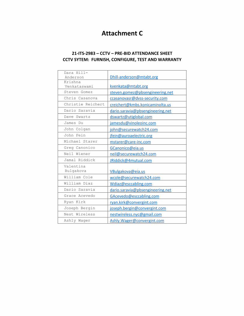
Attachment C
21-ITS-2983 – CCTV – PRE-BID ATTENDANCE SHEETCCTV SYTEM: FURNISH, CONFIGURE, TEST AND WARRANTY
Dara Hill- Anderson [email protected] Krishna Venkataswami [email protected] Steven Gomez [email protected] Chris Casanova [email protected]
Christie Reichert [email protected]
Dario Saravia [email protected] Dave Swartz [email protected]
James Du [email protected]
John Colgan [email protected] John Fein [email protected] Michael Starer [email protected]
Greg Canonico [email protected]
Neil Wiener [email protected]
Jamal Riddick [email protected]
Valentina Bulgakova [email protected]
William Cole [email protected]
William Diaz [email protected]
Dario Saravia [email protected] Grace Acevedo [email protected]
Ryan Kirk [email protected]
Joseph Bergin [email protected]
Nest Wireless [email protected] Ashly Wager [email protected]
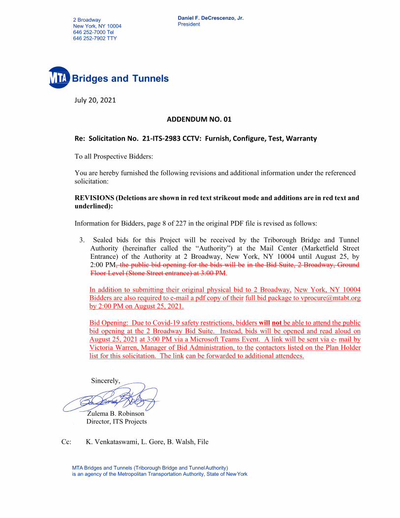
MTA Bridges and Tunnels (Triborough Bridge and Tunnel Authority) is an agency of the Metropolitan Transportation Authority, State of New York
2 Broadway New York, NY 10004 646 252-7000 Tel 646 252-7902 TTY
Daniel F. DeCrescenzo, Jr. President
Bridges and Tunnels
July 20, 2021
ADDENDUM NO. 01
Re: Solicitation No. 21-ITS-2983 CCTV: Furnish, Configure, Test, Warranty
To all Prospective Bidders: You are hereby furnished the following revisions and additional information under the referenced solicitation:
REVISIONS (Deletions are shown in red text strikeout mode and additions are in red text and underlined):
Information for Bidders, page 8 of 227 in the original PDF file is revised as follows:
3. Sealed bids for this Project will be received by the Triborough Bridge and Tunnel Authority (hereinafter called the “Authority”) at the Mail Center (Marketfield Street Entrance) of the Authority at 2 Broadway, New York, NY 10004 until August 25, by 2:00 PM, the public bid opening for the bids will be in the Bid Suite, 2 Broadway, Ground Floor Level (Stone Street entrance) at 3:00 PM.
In addition to submitting their original physical bid to 2 Broadway, New York, NY 10004 Bidders are also required to e-mail a pdf copy of their full bid package to [email protected] by 2:00 PM on August 25, 2021.
Bid Opening: Due to Covid-19 safety restrictions, bidders will not be able to attend the public bid opening at the 2 Broadway Bid Suite. Instead, bids will be opened and read aloud on August 25, 2021 at 3:00 PM via a Microsoft Teams Event. A link will be sent via e- mail by Victoria Warren, Manager of Bid Administration, to the contactors listed on the Plan Holder list for this solicitation. The link can be forwarded to additional attendees.
Sincerely,
Zulema B. Robinson Director, ITS Projects
Cc: K. Venkataswami, L. Gore, B. Walsh, File