TMM3 Stretcher-Chair Owners Operating and Maintenance …
28
Document #OM-TMM-2228-13 REV V S SHORT BASE F FOLDING FOOTREST E EXPORT B BATTERY A AC POWER TMM3 STRETCHER-CHAIR OWNERS OPERATING & MAINTENANCE MANUAL VIDEO FLUOROSCOPY ONE PATIENT, ONE SURFACE® IMPORTANT - DO NOT DISCARD THIS MANUAL. KEEP THIS MANUAL FOR FUTURE REFERENCE AND TRAINING. OPTIONS
Transcript of TMM3 Stretcher-Chair Owners Operating and Maintenance …

Document #OM-TMM-2228-13 REV V
S SHORT BASE
F FOLDING FOOTREST
E EXPORT
B BATTERY
A AC POWER
TMM3 STRETCHER-CHAIROWNERS OPERATING & MAINTENANCE MANUAL
VIDEO FLUOROSCOPY
ONE PATIENT, ONE SURFACE®
IMPORTANT - DO NOT DISCARD THIS MANUAL. KEEP THIS MANUAL FOR FUTURE REFERENCE AND
TRAINING.
OPTIONS

OWNERS OPERATING & MAINTENANCE MANUALTMM3 VIDEO FLUOROSCOPY STRETCHER-CHAIR
Page 2 of 28
Document #OM-TMM-2228-13Revision: V
READ AND FAMILIARIZE YOURSELF WITH ALL INSTRUCTIONS BEFORE USING THIS PRODUCT.
Do NOT install, maintain, or operate this equipment without reading and following this manual otherwise injury and/or damage may result.
IF YOU HAVE ANY QUESTIONS OR CONCERNS, PLEASE CONTACT WINCO MFG., LLC.
Winco assumes no responsibility for damage or injury caused by improper assembly, installation, use, or maintenance of these products.
No part of this manual may be duplicated in any form without the prior consent of Winco Mfg., LLC. Unauthorized duplication and/or distribution of these materials may result in civil prosecution to the maximum extent allowed by law.
SAVE THESE INSTRUCTIONS FOR FUTURE REFERENCE.
NOTE: Contents of this document are subject to change without notice.
Please refer to wincomfg.com to be sure you are utilizing the most current version.
SIGNAL WORDS / SYMBOLSThe following signal words and symbols are used throughout this manual to call out hazards which could result in injury or property damage:
Indicates an imminently hazardous situation which, if not avoided, will result in death or serious injury.
Indicates a potentially hazardous situation which, if not avoided, could result in death or serious injury.
Indicates a potentially hazardous situation which, if not avoided, may result in minor or moderate injury. It may also be used to alert against unsafe practices or potential property damage hazards.
Provides important information, makes special instructions clearer, or provides service personnel information to make maintenance easier.

OWNERS OPERATING & MAINTENANCE MANUALTMM3 VIDEO FLUOROSCOPY STRETCHER-CHAIR
Page 3 of 28
Document #OM-TMM-2228-13Revision: V
TABLE OF CONTENTSSignal Words / Symbols .................................................................................................................. 2
Intended Use Statement .................................................................................................................. 4
Transportation, Storage, Handling & Disposal ..................................................................... 4
Preparation: Before you begin ..................................................................................................... 4
Power / Cable Requirements .......................................................................................................... 5
Safety Precautions ........................................................................................................................... 5Warnings ..................................................................................................................................................................... 5Accessory Warnings ............................................................................................................................................. 6Cautions ...................................................................................................................................................................... 7EMI Cautions .............................................................................................................................................................. 8Notices ......................................................................................................................................................................... 9
Product Labels / Diagrams ............................................................................................................. 10Options ......................................................................................................................................................................... 11
Operating Instructions ................................................................................................................... 12Quick Release Back Section ............................................................................................................................... 12Caster Brake Operation ...................................................................................................................................... 13Side Rail Operation ................................................................................................................................................. 13Adjusting Side Rail Angle ................................................................................................................................... 14Pendant (Controller) ........................................................................................................................................... 15Patient Ingress / Egress ....................................................................................................................................... 16Patient Transfer ...................................................................................................................................................... 17Push Bar Operation ............................................................................................................................................... 17Seat Rotation ............................................................................................................................................................ 18
Options .................................................................................................................................................. 19“S” Option: Short Base .......................................................................................................................................... 19“F” Option: Manual Folding Footrest .......................................................................................................... 19“E” Option: Export ................................................................................................................................................... 19“B” Option: Battery Pack ...................................................................................................................................... 20“A” Option: AC Power (for on-board batteries and charger) ............................................................ 21
Switch Schematic ............................................................................................................................... 22
Cleaning Information ...................................................................................................................... 22
Pad Set Care ....................................................................................................................................... 23Removing TMM Pads / Pad Sets From Stretcher-Chair ......................................................................... 23
Preventative Maintenance .............................................................................................................. 24
Battery Safety Information ........................................................................................................... 24
Warranty Information ..................................................................................................................... 26Limited Warranty ..................................................................................................................................................... 26Optional Extended Limited Warranty ........................................................................................................... 26
Service and Contact Information ............................................................................................... 27

OWNERS OPERATING & MAINTENANCE MANUALTMM3 VIDEO FLUOROSCOPY STRETCHER-CHAIR
Page 4 of 28
Document #OM-TMM-2228-13Revision: V
INTENDED USE STATEMENTTMM3 Stretcher-Chairs are intended for use in patient treatment, transport and/or recovery within a hospital, clinic, same-day/ambulatory surgery center, or similar environment.
The pendant control is NOT INTENDED FOR PATIENT USE.
A surgeon and/or clinician must always rely on his or her own clinical knowledge when deciding whether to use a TMM3 Stretcher-Chair when treating a patient.
TRANSPORTATION, STORAGE, HANDLING & DISPOSAL• The product should be transported in factory packaging, inside an appropriate medium for the
destination, i.e., air/sea cargo containers.
• The product should be stored in an environment that will inhibit rust/mold formation.
• Winco Mfg., LLC recommends not leaving the product in the factory packing in excess of three (3) months.
• The product should always be handled in a manner consistent with the user instructions and in a manner to prevent contamination after each use.
• The product has many recyclable components and, to the extent practical, all effort should be used to recycle responsibly. Otherwise the product components shall be disposed of in accordance with local statues.
PREPARATION: BEFORE YOU BEGINCarefully examine your product for any damage. Be sure to inspect all components.
1. IF DAMAGE IS EVIDENT, CONTACT FREIGHT CARRIER OR WINCO IMMEDIATELY.
2. Remove all packaging material and any hardware that was secured for shipping.
3. Carefully remove all components and any included tools and/or parts from the carton.
4. You may need to cut packaging materials with a box cutter or scissors to access the product. Use CAUTION to avoid personal injury or damage to the product.
5. Save all boxes and packaging material until AFTER you have assembled your product and have verified that all components are functioning properly. These material are required if it becomes necessary to return the product.
6. DO NOT install, maintain or operate this equipment without reading and following this manual otherwise injury and/or damage may result. IF YOU HAVE QUESTIONS OR CONCERNS PLEASE CONTACT WINCO MFG., LLC.
WINCO ASSUMES NO RESPONSIBILITY FOR DAMAGE OR INJURY CAUSED BY IMPROPER ASSEMBLY, INSTALLATION, USE, OR MAINTENANCE OF THESE PRODUCTS.

OWNERS OPERATING & MAINTENANCE MANUALTMM3 VIDEO FLUOROSCOPY STRETCHER-CHAIR
Page 5 of 28
Document #OM-TMM-2228-13Revision: V
POWER / CABLE REQUIREMENTSFor options A, B & E, see the "Options" section of this manual for additional details regarding powering this product.
Only use the power/charging cord that came with your TMM3 Video Fluoroscopy Stretcher-Chair.
SAFETY PRECAUTIONSWARNINGS
CHAIR OPERATION BY QUALIFIED, TRAINED MEDICAL PERSONNEL ONLY The chair is intended to be operated only by qualified, trained medical staff. Operation of chair by unauthorized, untrained and/or lay people must be avoided.
USE CAUTION ON RAMPSControl chair when traversing ramps. If a collision occurs, serious injury to patient, bystanders, or medical personnel and damage to chair or medical facility could occur.
LOCK CASTERS BEFORE PATIENT EGRESS AND INGRESSPrior to patient egress and ingress, casters must be locked by pressing the red end down on any of the brake pedals located on the base of the chair.
AVOID PINCH POINTS AND OTHER INJURIESTo prevent serious injury, ensure extremities of patient and bystanders are clear of all mechanical systems when operating motors for lift and positioning functions.
To prevent pinch / crush injury, ensure extremities of patient and bystanders are clear of locking mechanism when raising and lowering side rails.
To prevent patient strangulation, use approved hand pendant storage location when not in use. See PENDANT section for additional information.
BATTERY CAN EXPLODE DUE TO OFF-GASSING WHEN CHARGINGAt end of charging process (or with overcharge conditions), battery can produce mixture of explosive gases (including hydrogen and oxygen). Avoid exposing battery to open flames, cigarettes, sparks, and incandescent materials.
Never charge battery in enclosed, unventilated spaces.
Do NOT store battery in sealed container. Store in fresh, well-ventilated area protected from direct sunlight and heat sources.
Do NOT use water to extinguish battery fire. Use dry powder, foam CO2 extinguisher.
USE FACTORY APPROVED BATTERIES ONLYUse of non-factory approved batteries will void all warranties and could result in unsatisfactory performance and/or damage.

OWNERS OPERATING & MAINTENANCE MANUALTMM3 VIDEO FLUOROSCOPY STRETCHER-CHAIR
Page 6 of 28
Document #OM-TMM-2228-13Revision: V
USE CAUTION WHEN STORING OXYGEN CYLINDER UNDER CHAIRTo prevent severe gas leakage or rupture of compressed gas cylinder, when placing cylinder under chair, ensure adequate clearance between cylinder and its attached gas equipment (i.e. regulator, gauges, fittings, knobs) and all adjustable chair sections and/or features (i.e. seat, back, leg, rails, actuators).
To prevent fire and/or explosive hazard, do not leave chair (and stowed oxygen equipment) near heat source.
To prevent gas equipment damage during transport, ensure cylinder sets in cradle properly and strap mechanisms are secured tightly. Chair is intended to accommodate up to an E-size cylinder (4 3/8” outer diameter x 25” length).
DO NOT PLACE EXCESSIVE WEIGHT ON ENDSPosition patient’s body weight uniformly over the patient surface. Use caution when shifting patient’s body weight towards either end of the stretcher-chair. Excessive weight on either end of the device could cause the stretcher-chair to become unstable.
Do not sit or stand on the ends of the stretcher-chair. Instruct patients to not stand on footrest during egress or ingress.
Due to the unique nature of each patient’s body shape, caregiver should exercise sound judgment when positioning patient on the device.
ACCESSORY WARNINGS• To prevent serious injury and property damage, review Operating Manuals for all medical
equipment and accessories that may be used with, or attached to, this chair.
• Using the supplied accessories in the incorrect manner may cause patient, bystander, or facility harm.
• If chair is equipped with accessory belts, refer to the appropriate Field Installation and Usage Instructions (provided with belts) for proper installation, use, and care.
• To prevent fire hazards, follow all precautions and operating procedures prescribed by suppliers of oxygen administering equipment (i.e. oxygen gas regulators, tents, masks, cannulas, etc.)
• To prevent injury and property damage, total weight of items placed on “IV” pole must be less than 25 pounds.
• If mounting accessories to back surgical rails, ensure accessory is properly installed and securely engaged prior to transporting patient or chair and prior to use. Only equipment approved by TransMotion by Winco is to be mounted on surgical rails. TransMotion by Winco is not responsible for damage and assumes no liability caused by the use of unapproved equipment or accessories. Approved medical equipment includes tools, instruments, or scopes that are compatible with a 0.365” thick by 1.125” wide surgical rail.
SAFETY PRECAUTIONS: CONTINUED

OWNERS OPERATING & MAINTENANCE MANUALTMM3 VIDEO FLUOROSCOPY STRETCHER-CHAIR
Page 7 of 28
Document #OM-TMM-2228-13Revision: V
CAUTIONS
DO NOT MODIFY CHAIR Modifying chair can cause unpredictable operation resulting in injury to patient, medical personnel, or bystander. Modifying chair will void warranty and may cause unsafe operating conditions.
USE SAFE OPERATING PROCEDURES Prior to operating chair, ensure patient clearance by moving any overhanging equipment or moving chair from under a table to prevent patient injury.
TMM3 must be at least 20" from nearest wall or obstruction to allow for full range of activation.
Leave chair in lowest position whenever possible. This practice will decrease potential injury during an unsupervised patient egress from chair.
Prior to patient transport in chair, raise side rails and ensure latching mechanism is in locked position. Medical personnel must determine degree of restraint needed to ensure patient’s safety during transport.
To prevent personal injury to medical personnel and/or patient, ensure the back extension is properly installed and securely engaged prior to transporting patient/chair, and prior to use of IV system.
For “F” Option Only: Since footrest is foldable (not locked in position), ensure protection of patient’s feet while moving chair in close quarters (i.e. elevators, crowded hallways, procedure rooms).
INSPECT AND CLEAN CHAIR REGULARLY Inspect cushions after each use. Discontinue use if upholstery is ripped, cut, or torn, which could allow fluids to enter cushion. This practice will prevent infection of patients and medical personnel and contamination of medical equipment.
Do NOT use machine / pressure / power wash procedures on chair. After each use in a clinical setting, hand wash all patient-contact surfaces (i.e. cushions, rails) and plastic base cover with warm water and mild detergent.
For “A” Option Only: For large fluid spills on chair, immediately unplug chair from AC wall outlet.
PLUG CHAIR INTO PROPERLY GROUNDED WALL OUTLET MARKED “HOSPITAL ONLY” OR “HOSPITAL GRADE”
For “A” Option Only: Chair is equipped with hospital-grade three-prong plug for protection against electric shock and must be plugged into properly grounded hospital-grade wall outlet.

OWNERS OPERATING & MAINTENANCE MANUALTMM3 VIDEO FLUOROSCOPY STRETCHER-CHAIR
Page 8 of 28
Document #OM-TMM-2228-13Revision: V
SAFETY PRECAUTIONS: CONTINUED
MAXIMUM WEIGHT OF BACK SURGICAL BAR The maximum weight capacity of each back surgical bar is 50 pounds. To prevent personal injury to patient, do not mount equipment weighing more than 50 pounds to device. Weight of patient plus weight of equipment should not exceed 500 pound weight capacity of TransMotion by Winco stretcher-chair.
EMI CAUTIONS
EMI MAY AFFECT CHAIR FUNCTIONALITYChair may be susceptible to EMI (Electromagnetic Interference) caused by electromagnetic energy emitted from various sources, such as, radio and television stations, amateur radio (HAM) transmitters, citizen band (CB) radios, hand-held “walkie-talkies”, security / police / fire transceivers and other communication devices. EMI can cause chair to move by itself, or in an unintended fashion. It can damage control system(s).
Intensity of interfering energy is measured in V/m (volts per meter). Chair can resist EMI up to a certain intensity, called its “immunity level”. When the immunity level is higher, the less likely EMI will interfere with chair operation. The chair has been tested to 20 V/m immunity level, which is sufficient to provide useful protection from common sources of radiated electromagnetic energy.
In clinical environments devices can emit electromagnetic energy which becomes more intense as one moves closer to energy source. To reduce chance of unintended movement or operation of chair, observe the following:
• Be aware of nearby high-power transmitters (radio and TV stations), MRI (magnetic resonance imaging) systems, and NMR (nuclear magnetic resonance) imaging systems. Keep chair away from these areas.
• Do not operate hand-held transmitters near chair.
• Do not operate chair near others using hand-held transmitters.
• If unintended chair movement occurs, disconnect battery and move chair away from location.

OWNERS OPERATING & MAINTENANCE MANUALTMM3 VIDEO FLUOROSCOPY STRETCHER-CHAIR
Page 9 of 28
Document #OM-TMM-2228-13Revision: V
NOTICES
MAXIMUM PATIENT WEIGHT IS 350 POUNDS (158 KG)Maximum patient weight capacity of chair is 350 pounds. If exceeded, damage to chair could occur.
CHAIR IS INTENDED FOR INDOOR USE ONLYTo ensure proper operation and extend chair life, only use chair in specified environment.
USE CDC’S UNIVERSAL PRECAUTIONSWhen maintaining chair after clinical use, service personnel must use UNIVERSAL PRECAUTIONS as defined by CDC (Centers for Disease Control and Prevention).
MAINTAIN CHAIR REGULARLYTo ensure proper operation and extend chair life, inspect, maintain, and service chair on a regular basis. Inspection, maintenance, and service details are located later in this manual.
REMOVE BATTERY DURING CHAIR STORAGE
For “B” Option Only: If chair is to be stored or not in use for four (4) days or more, remove battery pack from chair. Refer to Battery Charger Installation and Usage Instructions (IM TMA57-15), under the “Cautionary Usage Instructions” section, for more information.
For “A” Option Only: If chair is to be stored or not in use for four (4) days or more, leave chair plugged into an AC wall outlet or unplug battery from control box. For more information, refer to “A” Option section below.
USE ONLY FACTORY APPROVED BATTERIESUse of unapproved batteries will void warranty.

OWNERS OPERATING & MAINTENANCE MANUALTMM3 VIDEO FLUOROSCOPY STRETCHER-CHAIR
Page 10 of 28
Document #OM-TMM-2228-13Revision: V
PRODUCT LABELS / DIAGRAMSINSPECT LABELS PERIODICALLY
Every three (3) months, inspect all labels and ensure they are legible and not tattered, torn or missing.
Refer to the label locations in figure below. If labels need replacing, contact TransMotion by Winco Customer Service at 1-800-237-3377.
Item No. Part No. Label Name1 TMM-2247-10 Video QR Code
2 TMM-204-10 Rotation Operation
3 N/A Serial Number
4 TMM-225-10 Seat Lock Knob
5 TMM-270-10 Max Weight Capacity
6 TMM-205-10 Aluminium Equivalency
7TMM-1218-10 TMM-1219-10
TMM3 Base Label (Left / Right)
8 TMM-679-10 TMM3 End Label
9 TMM-202-10 Chair End Warning

OWNERS OPERATING & MAINTENANCE MANUALTMM3 VIDEO FLUOROSCOPY STRETCHER-CHAIR
Page 11 of 28
Document #OM-TMM-2228-13Revision: V
OPTIONS
"A" A/C POWER OPTION "B" BATTERY POWER OPTION
1 TMM-208-10 Power Light Label 1 TMA57-15 Universal Charger Assembly
2 TMM-222-10 Charge Battery Label 2 TMM-523-10 Battery Removal Label
"E" EXPORT PLUG OPTION "F" FOLDING FOOTREST OPTION
1 TMM-1057-XX Power Cord - Universal Charger 1 TMM-202-10 Chair End Warning Label

OWNERS OPERATING & MAINTENANCE MANUALTMM3 VIDEO FLUOROSCOPY STRETCHER-CHAIR
Page 12 of 28
Document #OM-TMM-2228-13Revision: V
OPERATING INSTRUCTIONSQUICK RELEASE BACK SECTION
1. LOCATE MANUAL QUICK RELEASE LEVER
Back section quick release (red) lever is located under seat on patient’s right side.
2. ACTIVATE RELEASE LEVER
To activate quick release of back section, pull the red lever out. When weight is applied, the back section will drop until the lever is released.
Note: Quick release feature is intended for emergency purposes only.
PRIOR TO PERFORMING CHEST COMPRESSIONS ON A PATIENT, FIRST AND FOREMOST, THE PATIENT SHOULD BE MOVED TO A MORE STABLE, NON-PADDED PLATFORM. SECONDARILY, IF ATTEMPTING TO PERFORM CHEST COMPRESSIONS ON THE TMM DEVICE, THE PATIENT SHOULD BE PLACED ON A BACK BOARD AND POSITIONED ON THE CHAIR SO THE PATIENT’S CHEST CAVITY IS OVER, OR AS CLOSE TO, THE COLUMN SUPPORT AS POSSIBLE. IT IS THE RESPONSIBILITY OF THE MEDICAL PROFESSIONAL TO DETERMINE WHETHER CPR CAN BE EFFECTIVELY PERFORMED ON THIS CHAIR ON A CASE-BY-CASE BASIS.
DO NOT TWIST OR ADJUST THE DAMPER. DOING SO COULD RESULT IN THE BACK RELEASE LEVER FUNCTIONING IMPROPERLY DURING AN EMERGENCY.
Note: To ensure proper operation, activate quick release every thirty days. If quick release does not operate properly, please contact Customer Service at 1-800-237-3377.

OWNERS OPERATING & MAINTENANCE MANUALTMM3 VIDEO FLUOROSCOPY STRETCHER-CHAIR
Page 13 of 28
Document #OM-TMM-2228-13Revision: V
CASTER BRAKE OPERATION
• BRAKE MODE: To activate, press down on red end of either brake pedal located at base of chair.
Note: Brake mode prevents all four casters from swiveling and all wheels from spinning.
• NEUTRAL MODE: To activate, place either brake pedal into a horizontal position (as shown).
Note: Neutral mode allows all four casters to swivel and all wheels to spin freely.
• STEER MODE: To activate, press down on green end of either brake pedal located at base of chair.
Note: Steer mode locks caster (near patient’s right foot) parallel to base, but allows this wheel to spin. The other three casters swivel and wheels spin freely.
SIDE RAIL OPERATION• LOWERING SIDE RAIL
Grasp top of side rail and push inward slightly, while pulling out red rail release tab. Once released, lower rail.
Once the side rail latch is deactivated, the rail can be lowered into the "down" position (below the seat).

OWNERS OPERATING & MAINTENANCE MANUALTMM3 VIDEO FLUOROSCOPY STRETCHER-CHAIR
Page 14 of 28
Document #OM-TMM-2228-13Revision: V
OPERATING INSTRUCTIONS: CONTINUED
• STOWING SIDE RAIL
Once the rail is lowered (“down” position), push the rail to fully engage the side rail retainer clip.
• RAISING SIDE RAIL
Lift side rail until it is in “up” position.
NOTE: Red rail release tab will engage (lock) automatically. Ensure side rail is secure by pulling on rail after it is raised.
ADJUSTING SIDE RAIL ANGLE1. Remove cushion and seat pan by removing four pan head screws.
NOTICE: Do not discard seat pan head screws, or additional hardware removed during this step. Parts will be reused after adjustment.
2. Loosen top jam nut.
3. Adjust as needed:
a. To move inward, rotate bottom jam nut as shown.
b. To move outward, rotate bottom jam nut as shown.
4. Once adjustment is complete, re-tighten top jam nut and re-attach seat pan and cushion.
NOTICE• You do not need to hold bottom nut to
tighten top.• When adjusting, ensure bottom jam nut is contacting seat frame.• Ball joint head angle does not matter.• Prior to adjustment, pull outward on side rail in order for system to settle.• Ensure top jam nut engages at least two full threads.• Do not over tighten top jam nut (there is no need).
5. Reattach seat pan and cushion.

OWNERS OPERATING & MAINTENANCE MANUALTMM3 VIDEO FLUOROSCOPY STRETCHER-CHAIR
Page 15 of 28
Document #OM-TMM-2228-13Revision: V
PENDANT (CONTROLLER)
PENDANT IS NOT INTENDED FOR PATIENT’S USETo prevent damage, pendant can be stored at various locations on the chair when not in use.
ENSURE AREA IS CLEAR OF OBSTRUCTIONS PRIOR TO PENDANT USETo prevent property damage or injury to patient, survey area for possible obstructions prior to pendant use.
• BACK SECTION ADJUSTMENT: First row of pendant buttons adjusts angle of back section.
a. Press left button to raise chair back.
b. Press right button to lower chair back.
• LEG SECTION ADJUSTMENT: Second row of pendant buttons adjusts angle of leg section.
a. Press left button to raise chair’s leg section.
b. Press right button to lower chair’s leg section.
• SEAT HEIGHT ADJUSTMENT: Third row of pendant buttons adjusts height of seat section.
a. Press left button to raise chair’s seat.
b. Press right button to lower chair’s seat.
• SIMULTANEOUS LEG AND BACK SECTION (AUTO CONTOUR):Fourth row of pendant buttons controls simultaneous actuation of leg and back sections.
a. Press left button to raise chair’s leg section and lower chair’s back, resulting in stretcher configuration.
b. Press right button to lower chair’s leg section and raise chair’s back, resulting in chair configuration.

OWNERS OPERATING & MAINTENANCE MANUALTMM3 VIDEO FLUOROSCOPY STRETCHER-CHAIR
Page 16 of 28
Document #OM-TMM-2228-13Revision: V
PATIENT INGRESS / EGRESSPATIENT SHOULD NEVER BE PERMITTED TO ENTER OR EXIT FROM ENDS OF STRETCHER-CHAIR WHEN IN AN UPRIGHT, PARTIALLY, OR TOTALLY RECLINED POSITION. EXCESSIVE WEIGHT ON ENDS COULD CAUSE CHAIR TO TILT, RESULTING IN POSSIBLE PATIENT INJURY.
NOTICE: Follow these instructions for safe and proper patient ingress (entry onto chair) and egress (exit from chair).
a. Patient ingress and egress should always be made with chair in upright-chair position.
b. Patient must enter and exit from side of chair with their body weight centered over SEAT section.
c. See PATIENT TRANSFER section for instruction on transferring patient from one horizontal surface to another.
• PATIENT INGRESS (ENTRY)
1. Depress RED caster brake pedal to lock caster wheels.
2. Adjust chair to lowest height and into upright-chair position.
3. Lower one side rail of seat section.
4. If back section rails are present, remove / lower back section rail of same side.
5. Position patient (facing away from chair) at SEAT section.
6. WITH PATIENT ENTERING FROM SIDE OF CHAIR, assist patient while they sit down on SEAT section.
7. Once patient is fully seated, assist them in rotating their body in-line with chair into a seated position.
• PATIENT EGRESS (EXIT)
1. Depress RED caster brake pedal to lock caster wheels.
2. Adjust chair to lowest height and into upright-chair position.
3. Lower one side rail of seat section.
4. If back section rails are present, remove / lower back section rail of same side.
5. Ensure patient’s body weight is centered on SEAT section.
6. WITH PATIENT EXITING TO SIDE OF CHAIR, assist patient in rotating their body by placing their legs over one side of chair.
7. Assist patient into standing position from seated position.
OPERATING INSTRUCTIONS: CONTINUED

OWNERS OPERATING & MAINTENANCE MANUALTMM3 VIDEO FLUOROSCOPY STRETCHER-CHAIR
Page 17 of 28
Document #OM-TMM-2228-13Revision: V
PATIENT TRANSFERPATIENT’S BODY WEIGHT SHOULD NEVER BE SHIFTED TOWARDS EITHER END OF CHAIR WHEN IN A PARTIALLY, OR TOTALLY, RECLINED POSITION. SERIOUS PATIENT INJURY MAY OCCUR. ALL PATIENT TRANSFERS MUST BE MADE TO RIGHT SIDE OF TMM3-SERIES CHAIR, DUE TO SHAPE OF BACK SECTION, AND NOT TO CHAIR ENDS.
NOTICE: Follow these instructions for safe and proper patient transfer between chair (in stretcher orientation) and another horizontal surface.
1. Position back, seat, and leg sections into horizontal orientation. (Press Auto Contour button.)
2. Lower / remove all side rails from transfer (right) side of chair.
3. Position chair as close as possible to other surface.
4. Match chair (stretcher) height to height of bed or other horizontal surface.
5. Depress RED caster brake pedal to lock caster wheels.
6. Slide patient from one surface to other, following your facility’s standard practices / policies for lateral patient transfers.
PUSH BAR OPERATION• LOWERING PUSH BAR
1. Grasp push bar handle while pulling out red release knob.
2. Lower push bar into “down” position.
• RAISING PUSH BAR
Lift push bar handle until it is in “up” position.
NOTATION: The red release knob will engage (lock) automatically.
Lowering: STEP 1 Lowering: Step 2
OWNERS OPERATING & MAINTENANCE MANUALTMM3 VIDEO FLUOROSCOPY STRETCHER-CHAIR
Page 18 of 28
Document #OM-TMM-2228-13Revision: V
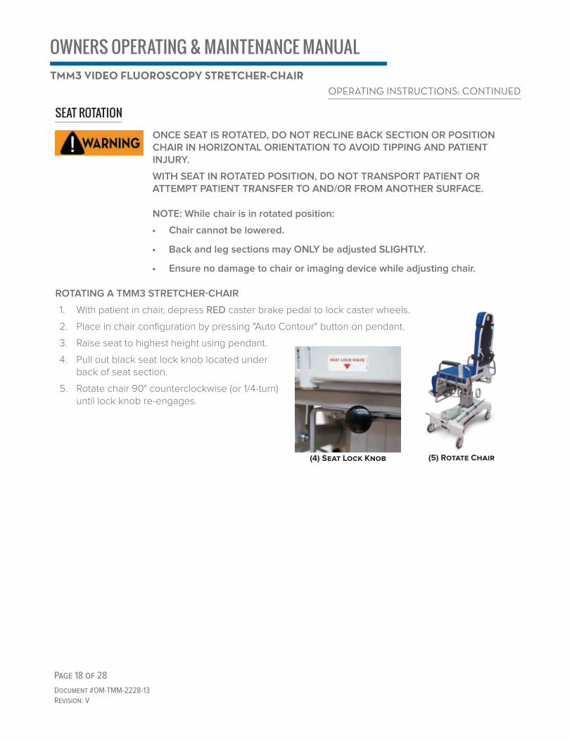
SEAT ROTATIONONCE SEAT IS ROTATED, DO NOT RECLINE BACK SECTION OR POSITION CHAIR IN HORIZONTAL ORIENTATION TO AVOID TIPPING AND PATIENT INJURY.
WITH SEAT IN ROTATED POSITION, DO NOT TRANSPORT PATIENT OR ATTEMPT PATIENT TRANSFER TO AND/OR FROM ANOTHER SURFACE.
NOTE: While chair is in rotated position:
• Chair cannot be lowered.
• Back and leg sections may ONLY be adjusted SLIGHTLY.
• Ensure no damage to chair or imaging device while adjusting chair.
ROTATING A TMM3 STRETCHER-CHAIR
1. With patient in chair, depress RED caster brake pedal to lock caster wheels.
2. Place in chair configuration by pressing "Auto Contour" button on pendant.
3. Raise seat to highest height using pendant.
4. Pull out black seat lock knob located under back of seat section.
5. Rotate chair 90° counterclockwise (or 1/4-turn) until lock knob re-engages.
OPERATING INSTRUCTIONS: CONTINUED
(4) Seat Lock Knob (5) Rotate Chair

OWNERS OPERATING & MAINTENANCE MANUALTMM3 VIDEO FLUOROSCOPY STRETCHER-CHAIR
Page 19 of 28
Document #OM-TMM-2228-13Revision: V
OPTIONS“S” OPTION: SHORT BASEFor “S” option, wheel base length is 26”.Standard wheel base length is 30”.
“F” OPTION: MANUAL FOLDING FOOTREST
WHEN POSITIONING FOOTREST, BE AWARE OF PINCH POINTS
NOTE: For patient comfort, stow footrest prior to articulating chair into supine (stretcher) position.
To stow footrest, place both hands on red handles and lift.
“E” OPTION: EXPORTThe “E” option designates a chair with a power cord specific to the receiving country (when that country is not the USA).
“A” option power cord is directly attached to chair.
“B” option power cord is attached to the battery charger (Item # TMA57-15).
NOTE: Power cords depicted in image may not match power cord shipped with your chair.
Manual Folding Footrest: Stowed
Manual Folding Footrest: Extended

OWNERS OPERATING & MAINTENANCE MANUALTMM3 VIDEO FLUOROSCOPY STRETCHER-CHAIR
Page 20 of 28
Document #OM-TMM-2228-13Revision: V
“B” OPTION: BATTERY PACK
• REMOVING BATTERY PACK FROM CHAIR
Grasp integrated handle on battery pack and pull away from chair until cam locks disengage. Remove battery from mounting bracket.
• INSTALLING BATTERY PACK ONTO CHAIR
Place two round, cam locks on back of battery into square openings of mounting bracket. Once in place, slide battery down (inward toward column) until cam locks engage.
For additional information, refer to the Installation and Usage Instructions for Battery Replacement (IM TMS-311-90).
• ADDITIONAL BATTERY INFORMATION
"B" option chairs come with an additional battery and a wall-mountable battery charger. The additional battery may be stored in the wall charger or on an optional mobile battery stand.
For more information related to the battery and charger, see "Battery Charger Installation and Usage Instructions" (IM TMA57-15).
OPTIONS: CONTINUED

OWNERS OPERATING & MAINTENANCE MANUALTMM3 VIDEO FLUOROSCOPY STRETCHER-CHAIR
Page 21 of 28
Document #OM-TMM-2228-13Revision: V
“A” OPTION: AC POWER (FOR ON-BOARD BATTERIES AND CHARGER)The AC power cord for charging on-board batteries is attached to the chair base and may be stowed by wrapping around storage bracket.
TO CHARGE ON-BOARD BATTERIES:• Insert AC plug into wall outlet.
NOTE: To prevent insufficient power, plug "A" option chairs in overnight to charge on-board batteries (i.e. during off-times), or 24 hours prior to service.
NOTE: When "A" option chairs are plugged in and charging the pendant will not illuminate, even when buttons are pushed.
NOTE: If your "A" option chair will be stored or not in use for more than 1 1/2 weeks, leave chair plugged into an AC wall outlet or unplug battery pack from control box.
TO UNPLUG ON-BOARD BATTERY PACK: 1. Lift up base cover to access control box.
2. Remove control box cover by unlocking mechanism using a flathead.
3. Slide the cover off to access the plugs.
4. Unplug the battery pack cord.
NOTE: ONLY use factory-approved on-board battery packs for stretcher-chairs with the "A" option. Use of non-approved on board battery packs will void warranty.
Stowed AC Power Cord
2. Unlock Control Box Mechanism
3. Slide Control Box Cover Off 4 Remove Battery Pack Cord

OWNERS OPERATING & MAINTENANCE MANUALTMM3 VIDEO FLUOROSCOPY STRETCHER-CHAIR
Page 22 of 28
Document #OM-TMM-2228-13Revision: V
SWITCH SCHEMATIC• "A" Option Only: Ground wire attaches to GROUND POST
• Battery cord plugs into PORT #13
• Plug column cord plug into phono din adapter, then plug into PORT #1
• PORT #2 is empty
• Back section actuator plugs into PORT #3
• Leg section actuator plugs into PORT #4
• PORT #5 is empty
• Seat rotation cord plugs into PORT #7
• Pendant cable plugs into PORT #9
• All excess wire should be placed in FRONT of the Control Box.
CLEANING INFORMATIONSTEAM AND/OR PRESSURE CLEANING CHAIR WILL VOID WARRANTY
TMM3 STRETCHER-CHAIR
Wipe TMM3 Stretcher-Chair (rails, base cover, etc.) with a damp cloth and allow to air dry.
NOTE: Clean exterior surfaces of electronics (actuators, battery pack, pendants) with minimal water.
Complete above steps as required and/or in accordance with facility policies.
A NOTE ABOUT CLEANING AGENTS
Facility approved detergents, disinfectants and water are suggested.
Use of facility approved detergents and disinfectants must comply with the instructions provided by the manufacturer(s) of those products.

OWNERS OPERATING & MAINTENANCE MANUALTMM3 VIDEO FLUOROSCOPY STRETCHER-CHAIR
Page 23 of 28
Document #OM-TMM-2228-13Revision: V
PAD SET CARE In general, all pads, pad sets and/or pillows should be:
1. Cleaned
2. Disinfected (in accordance with facility policy)
3. Rinsed
4. Allowed to air dry
It is important to note that the terms “disinfecting” and “cleaning” should not be used interchangeably.
Disinfectants alone will not provide adequate cleaning since they do not have the appropriate properties
to cut grease or oil and remove grime, hair or skin oils. The appearance, feel and performance of your
upholstery may diminish if not cleaned properly.
CLEANING YOUR TMM PADS / PAD SETS / PILLOWS:
Remove hair, grime and body oils. Your TransMotion pads/pillows should be cleaned on a regular basis
with a damp cloth soaked in a mild soap and water solution. Avoid harsh detergents or chemicals that
could damage the finish. If disinfecting with manufacturer approved chemicals or bleach, the pad/pillow
MUST be wiped off using clean water on a damp cloth and allowed to air dry as a final step. Failure to
rinse pads/pillows with clean water can result in a build-up of residues that, over time, may lead to drying,
cracking or other undesirable changes to appearance, feel and performance.
Please refer to any instructional tags that may have come with your product. Retain all instructional tags
for future use.
Contact the manufacturer of the fabric or vinyl used on your pads, pad sets and/or pillows for a current list
of approved disinfectants. Refer to the Vinyl and Cushion Information page on Winco's website for current
links to manufacturer materials.
REMOVING TMM PADS / PAD SETS FROM STRETCHER-CHAIR
When removing TMM pads / pad sets, pull laterally (toward
you). Do not pull from top to bottom.

OWNERS OPERATING & MAINTENANCE MANUALTMM3 VIDEO FLUOROSCOPY STRETCHER-CHAIR
Page 24 of 28
Document #OM-TMM-2228-13Revision: V
PREVENTATIVE MAINTENANCETo ensure proper operation and to extend the life of your stretcher-chair, it should be maintained on a regular basis per recommendations below.
PADS / PAD SETS / PILLOWS:After each use, inspect for tears. If torn, replace pad / pillow.
ALL RAILSEvery three months, inspect for chipped paint, burrs, and rough edges.
• Remove burrs and / or rough edges using a metal file in order to prevent cuts• Touch up any chipped paint (see our website for details regarding touch-up paint)
ALL FASTENED JOINTSEvery three months, inspect all fasteners to ensure proper fit and tightness. Retighten as needed.
ALL LABELSEvery three months, inspect for tattered, torn, missing, and illegible labels. Contact our Customer Service team to request new labels.
PENDANTS
Every three months, test each button to ensure proper function and inspect the pendant label to ensure it is readable. Contact our Customer Service team if your pendant is not functioning or if the label is unreadable
BATTERY SAFETY INFORMATIONTO PREVENT PERSONAL INJURY TO PATIENT AND / OR MEDICAL PERSONNEL, ENSURE BATTERY REPLACEMENT IS PROPERLY INSTALLED AND SECURELY ENGAGED PRIOR TO USE OF ACCESSORY.
TO PREVENT PERSONAL INJURY TO PATIENT AND / OR MEDICAL PERSONNEL, ENSURE BATTERY REPLACEMENT IS INSTALLED BY PERSONNEL WHO HAVE THOROUGHLY READ INSTALLATION INSTRUCTIONS.
PROPERLY DISPOSE OF BATTERIES BEING REPLACED DURING SERVICING
• Battery posts, terminals and related components contain lead and lead compounds, which are known by the state of California to cause cancer or other reproductive harm. Wash hands thoroughly after handling or servicing.
• Lead batteries are classified as “dangerous waste” and service technicians are obliged by law to arrange for proper disposal of battery or recycling to avoid battery refuse in environment.
• Battery contains toxic material (lead) and corrosive fluid (sulfuric acid). Wear proper skin and eye protection prior to handling battery. After exposure, wash skin thoroughly with water.
• Do NOT short-circuit battery terminals, this can cause battery explosion or fire.
• To request Material Safety Data Sheet (MSDS) for battery, contact our Customer Service team.

OWNERS OPERATING & MAINTENANCE MANUALTMM3 VIDEO FLUOROSCOPY STRETCHER-CHAIR
Page 25 of 28
Document #OM-TMM-2228-13Revision: V
BATTERY LIFE
NOTE: Battery capacity diminishes over time. Charge batteries regularly to maintain healthy battery life. TransMotion by Winco recommends replacing your battery every two years or sooner if required.
Use of Batteries that are NOT factory approved will void any and all warranties.
SUGGESTED PROTOCOL FOR CHARGING BATTERIES FOR "B" OPTION STRETCHER-CHAIRS:
1. Ensure the cord for your TMM Battery Charger is fully inserted into the battery charger inlet.
2. Plug your TMM Battery Charger directly into an outlet. Do NOT use an extension cord or power strip. Extension cords and/or power strips can cause a drop in current that may hinder the charger’s ability to charge the battery efficiently.
3. Slide the TMM Battery downward onto the TMM Battery Charger making sure the battery is properly seated onto the charging port.
4. Check to see if either an orange light (indicating the battery is “charging”) or a green light (indicating the battery is “fully charged”) appears.
5. Charge your TMM Battery for eight (8) hours or until the Green light indicator appears to ensure an optimum charge is achieved.
6. Rotate batteries from charger to chair every two (2) to three (3) days to maintain an optimum charge on the batteries.
7. When your TMM Stretcher-Chair is not in use for extended periods of time (four (4) days or more) unplug the battery from the Stretcher-Chair to prevent battery drainage.
8. Replace your TMM Battery every two (2) years (recommended) or as required.

OWNERS OPERATING & MAINTENANCE MANUALTMM3 VIDEO FLUOROSCOPY STRETCHER-CHAIR
Page 26 of 28
Document #OM-TMM-2228-13Revision: V
WARRANTY INFORMATIONLIMITED WARRANTYWinco Mfg., LLC provides the following Limited Warranty covering defects in materials and workmanship on TransMotion by Winco products:
• 7-Year / Lifetime Warranty for Frame / Welds
• 2-Year Warranty on Components (*excludes batteries and any necessary labor)
The Limited Warranty period begins when the product is delivered to the Buyer.
The Limited Warranty applies when the product is used and cared for as specified by Winco Mfg., LLC. If the product is not used and cared for as specified, the Limited Warranty is void. Adjustments under this Limited Warranty will be made only after completion of inspection of the part or product by Winco Mfg., LLC. Winco Mfg., LLC’s liability under the Limited Warranty shall extend only to the replacement of any defective component or product as determined by Winco Mfg., LLC’s inspection.
Winco Mfg., LLC’s liability for any defective goods is limited to the invoice price or replacement cost of the defective product/component, whichever is lower.
The Limited Warranty for any product sold as a “demonstration unit” shall be limited to a period of one (1) year (frame/welds and components).
OPTIONAL EXTENDED LIMITED WARRANTYAs a supplement to your TransMotion by Winco Limited Warranty, you may elect to purchase an additional one, two, or three years of protection. The Extended Limited Warranty MUST be purchased within 364 days of the original purchase date.
A TransMotion by Winco Extended Limited Warranty applies when the product is used and maintained as specified by Winco Mfg., LLC. If the product is not used and maintained as specified, the Extended Limited Warranty is void.
Winco Mfg., LLC’s liability under the Extended Limited Warranty shall extend only to the replacement of any defective component or product as determined by Winco Mfg., LLC’s inspection.
Batteries and Pad Sets are excluded from all TransMotion by Winco warranties.
Products sold as demonstration units are only eligible for a One Year Extended Warranty. The Extended Warranty MUST be purchased within 364 days of the demonstration units purchase date.

OWNERS OPERATING & MAINTENANCE MANUALTMM3 VIDEO FLUOROSCOPY STRETCHER-CHAIR
Page 27 of 28
Document #OM-TMM-2228-13Revision: V
SERVICE AND CONTACT INFORMATIONCustomer service and support are important aspects of each TransMotion by Winco product.
Prior to contacting TransMotion by Winco for assistance with your chair, please HAVE YOUR CHAIR’S SERIAL NUMBER AVAILABLE (refer to label diagram for location).
Contact TransMotion by Winco Customer Service at:
TransMotion by WincoATTN. Customer Service5516 SW 1st LaneOcala, FL 34474-9307United States of America
Phone: 1-800-237-33771-352-854-2929
Fax: 1-352-854-9544
Manufacturer of Device:
Winco Mfg., LLC5516 SW 1st LaneOcala, FL 34474United States of America

TMM3: Video-Fluoroscopy Stretcher-ChairsOwner's Operation & Maintenance Manual
Document No.: OM-TMM-2228-13 Revision: V
INFORMATION CONTAINED WITHIN THIS DOCUMENT IS SUBJECT TO CHANGE WITHOUT NOTICE.THE MOST CURRENT INFORMATION CAN BE FOUND ON OUR WEBSITE.
CONTACT US To arrange a demonstration or to speak with one of our associates, please feel free to contact us at: 800-237-3377 | WincoMfg.com | 5516 SW 1st Lane, Ocala, FL 34474 | [email protected]
Copyright 2020 Winco Mfg., LLC
Effective 10.21.2020 - Revision V: Re branded updated layout, added warranty information