TM - Carnegie Mellon Universityegon.cheme.cmu.edu/esi/docs/pdf/Miller_CCSI... · TM Carbon Capture...
29
Overview for CAPD ESI Meeting David C. Miller, Ph.D. Technical Team Lead 11 March 2012 TM
Transcript of TM - Carnegie Mellon Universityegon.cheme.cmu.edu/esi/docs/pdf/Miller_CCSI... · TM Carbon Capture...
Overview for CAPD ESI Meeting David C. Miller, Ph.D. Technical Team Lead 11 March 2012
TM
2
TM
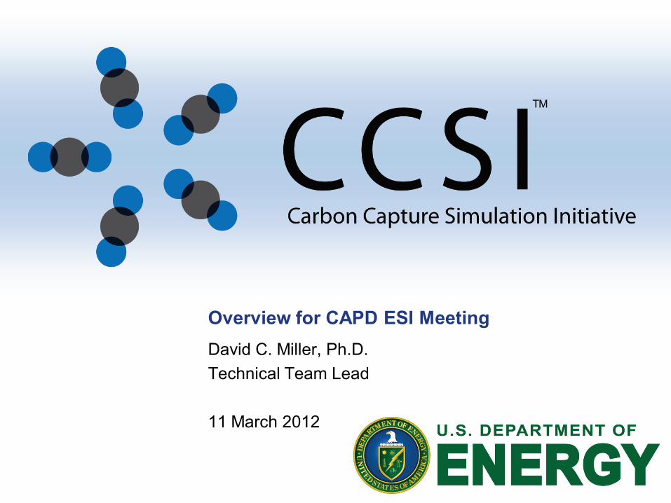
Carbon Capture Challenge • The traditional pathway from discovery to
commercialization of energy technologies can be quite long, i.e., ~ 2-3 decades
• President’s plan requires that barriers to the widespread, safe, and cost-effective deployment of CCS be overcome within 10 years
• To help realize the President’s objectives, new approaches are needed for taking carbon capture concepts from lab to power plant, quickly, and at low cost and risk
• CCSI will accelerate the development of carbon capture technology, from discovery through deployment, with the help of science-based simulations
Bench Research ~ 1 kWe
Small pilot < 1 MWe
Medium pilot 1 – 5 MWe
Semi-works pilot 20-35 MWe
First commercial plant, 100 MWe
Deployment, >500 MWe, >300 plants
3
TM
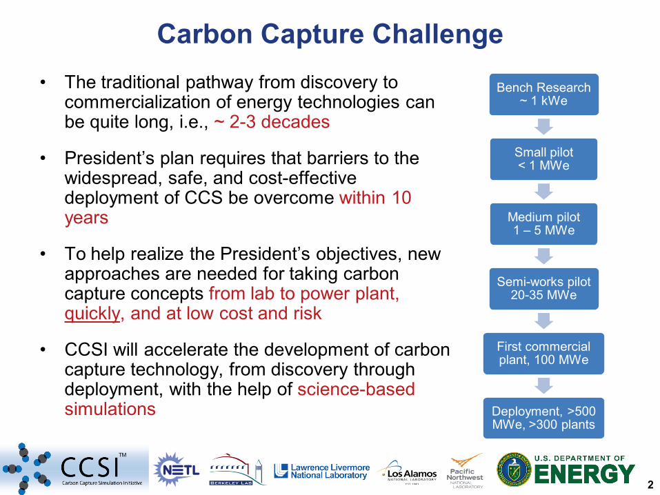
Carbon Capture Simulation Initiative
National Labs Academia Industry
Identify promising concepts
Reduce the time for design &
troubleshooting
Quantify the technical risk, to enable reaching
larger scales, earlier
Stabilize the cost during commercial
deployment
Essential for accelerating commercial deployment 1-31-2012
4
TM
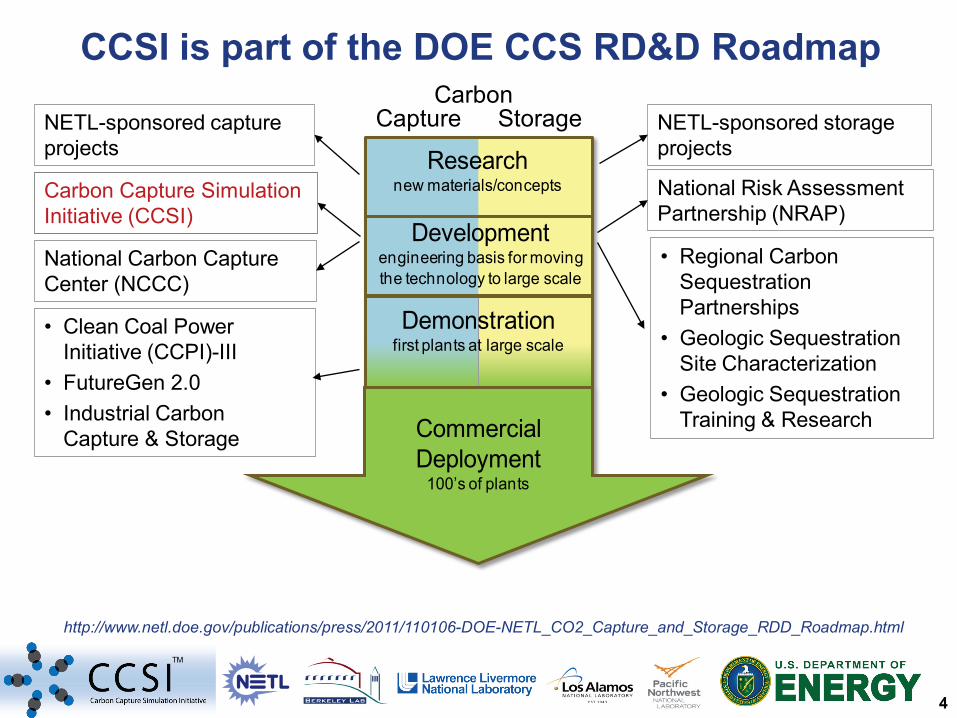
• Clean Coal Power Initiative (CCPI)-III
• FutureGen 2.0 • Industrial Carbon
Capture & Storage
• Regional Carbon Sequestration Partnerships
• Geologic Sequestration Site Characterization
• Geologic Sequestration Training & Research
CCSI is part of the DOE CCS RD&D Roadmap
Developmentengineering basis for moving the technology to large scale
Researchnew materials/concepts
Commercial Deployment
100’s of plants
Demonstrationfirst plants at large scale
Capture Storage Carbon
NETL-sponsored capture projects
Carbon Capture Simulation Initiative (CCSI)
National Carbon Capture Center (NCCC)
National Risk Assessment Partnership (NRAP)
NETL-sponsored storage projects
http://www.netl.doe.gov/publications/press/2011/110106-DOE-NETL_CO2_Capture_and_Storage_RDD_Roadmap.html
5
TM
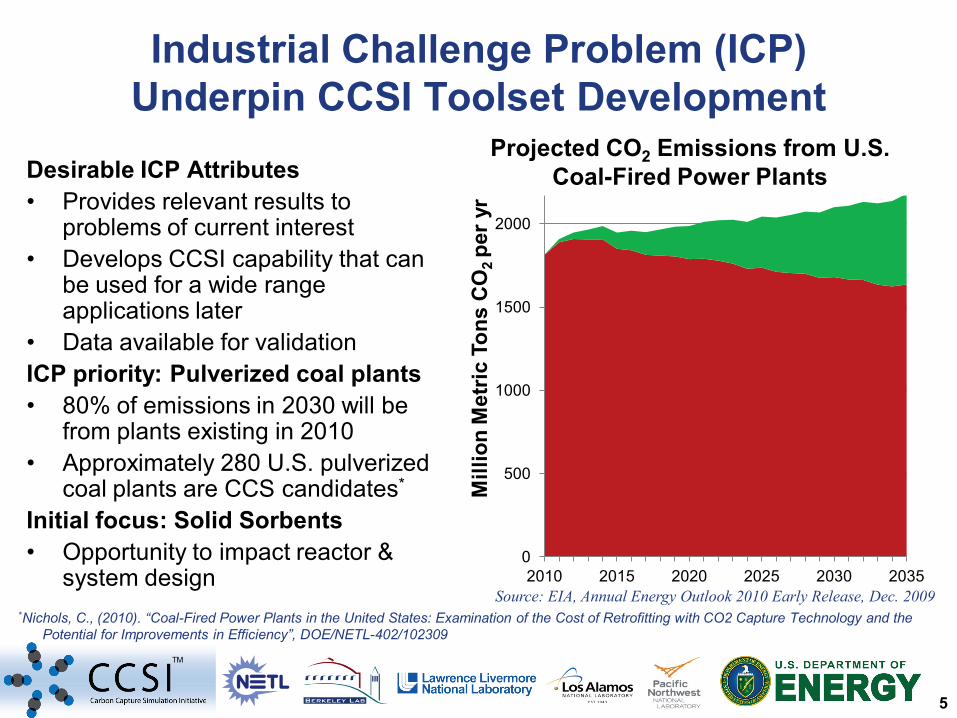
Industrial Challenge Problem (ICP) Underpin CCSI Toolset Development
Desirable ICP Attributes • Provides relevant results to
problems of current interest • Develops CCSI capability that can
be used for a wide range applications later
• Data available for validation ICP priority: Pulverized coal plants • 80% of emissions in 2030 will be
from plants existing in 2010 • Approximately 280 U.S. pulverized
coal plants are CCS candidates*
Initial focus: Solid Sorbents • Opportunity to impact reactor &
system design
*Nichols, C., (2010). “Coal-Fired Power Plants in the United States: Examination of the Cost of Retrofitting with CO2 Capture Technology and the Potential for Improvements in Efficiency”, DOE/NETL-402/102309
0
500
1000
1500
2000
2500
2010 2015 2020 2025 2030 2035
Mill
ion
Met
ric T
ons
CO
2 pe
r yr
Source: EIA, Annual Energy Outlook 2010 Early Release, Dec. 2009
Projected CO2 Emissions from U.S. Coal-Fired Power Plants
6
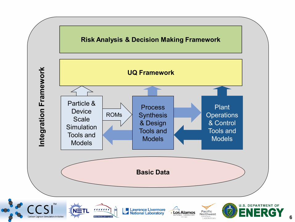
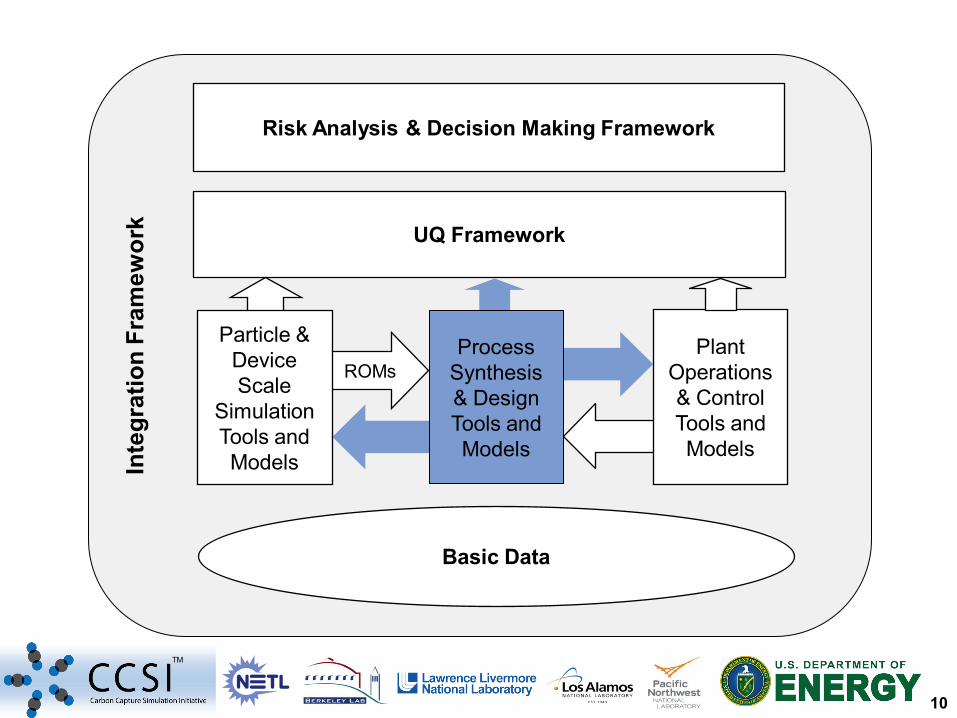
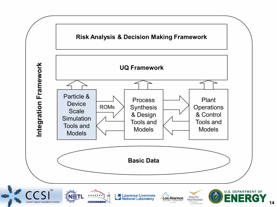
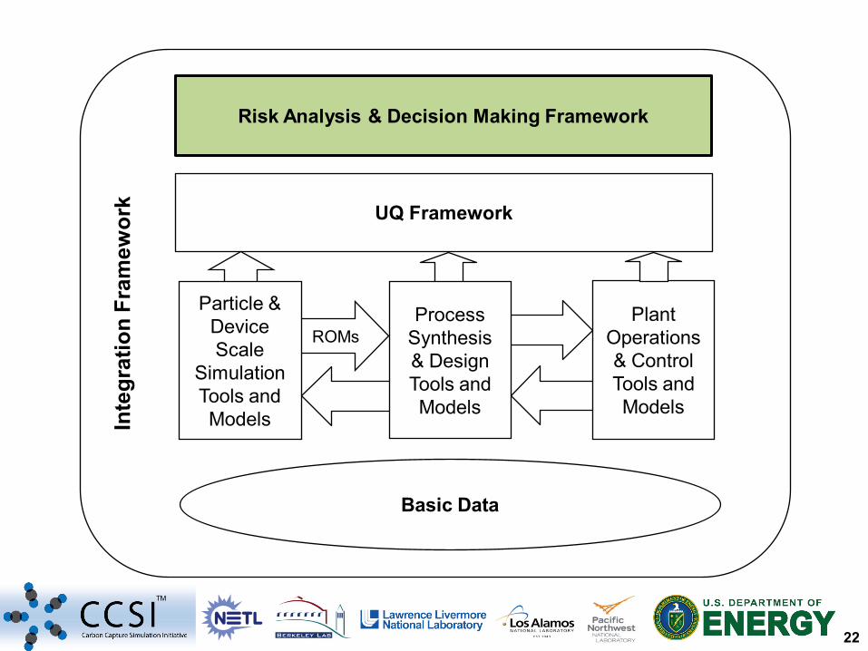
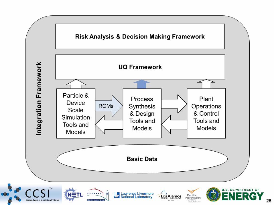
TM
Inte
grat
ion
Fram
ewor
k
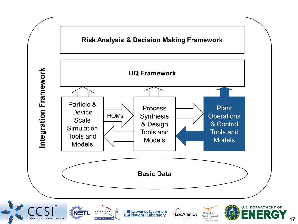
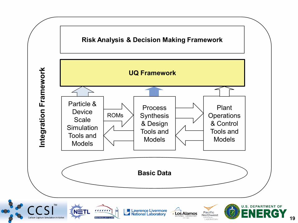
Basic Data
ROMs
UQ Framework
Risk Analysis & Decision Making Framework
Plant Operations & Control Tools and Models
Process Synthesis & Design Tools and Models
Particle & Device Scale
Simulation Tools and Models
7
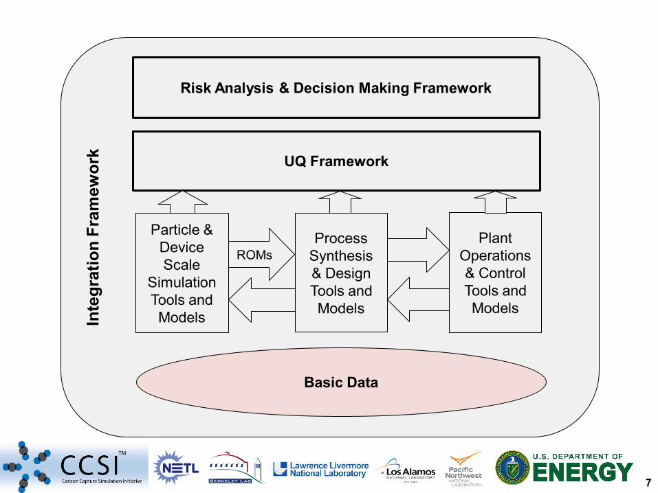
TM
Inte
grat
ion
Fram
ewor
k
Basic Data
ROMs
UQ Framework
Risk Analysis & Decision Making Framework
Plant Operations & Control Tools and Models
Process Synthesis & Design Tools and Models
Particle & Device Scale
Simulation Tools and Models
8
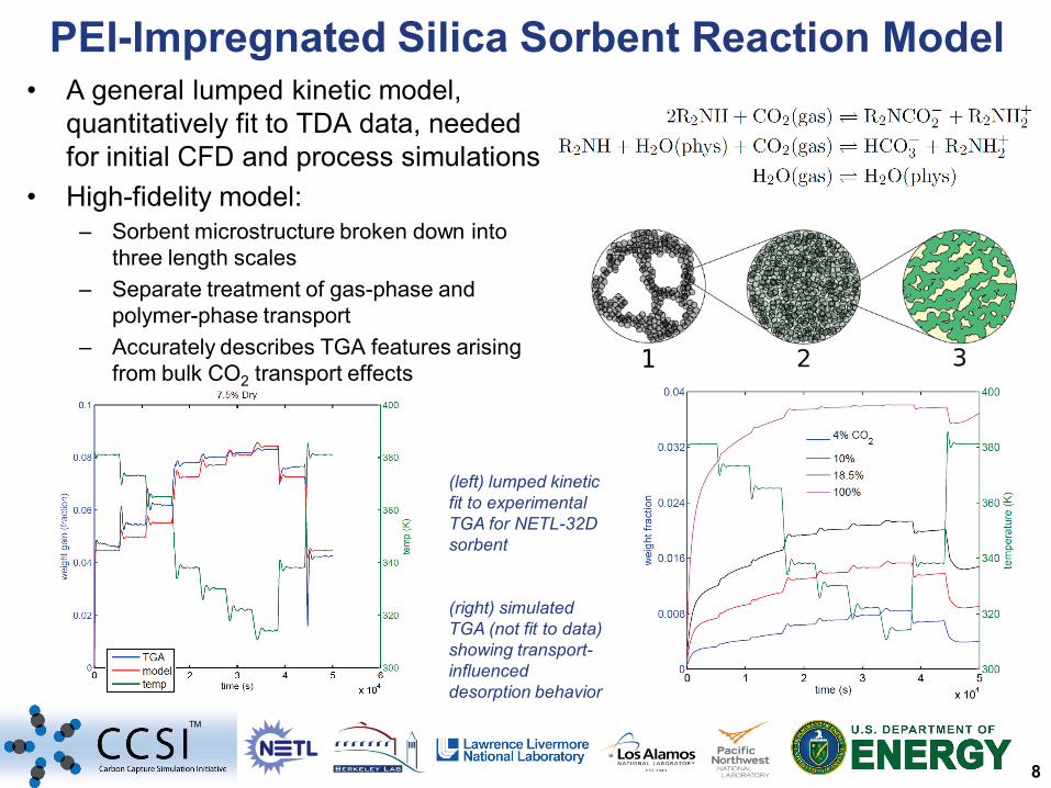
TM
PEI-Impregnated Silica Sorbent Reaction Model • A general lumped kinetic model,
quantitatively fit to TDA data, needed for initial CFD and process simulations
• High-fidelity model: – Sorbent microstructure broken down into
three length scales – Separate treatment of gas-phase and
polymer-phase transport – Accurately describes TGA features arising
from bulk CO2 transport effects
(left) lumped kinetic fit to experimental TGA for NETL-32D sorbent (right) simulated TGA (not fit to data) showing transport-influenced desorption behavior
9
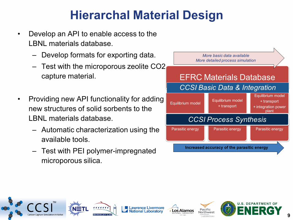
TM
• Develop an API to enable access to the LBNL materials database. – Develop formats for exporting data. – Test with the microporous zeolite CO2
capture material.
• Providing new API functionality for adding new structures of solid sorbents to the LBNL materials database. – Automatic characterization using the
available tools. – Test with PEI polymer-impregnated
microporous silica.
Hierarchal Material Design
EFRC Materials Database
Equilibrium model
Parasitic energy
Equilibrium model + transport
Parasitic energy
Equilibrium model + transport
+ integration power plant
Parasitic energy
Increased accuracy of the parasitic energy
More basic data availableMore detailed process simulation
CCSI Process Synthesis
CCSI Basic Data & Integration
10
TM
Inte
grat
ion
Fram
ewor
k
Basic Data
ROMs
UQ Framework
Risk Analysis & Decision Making Framework
Plant Operations & Control Tools and Models
Process Synthesis & Design Tools and Models
Particle & Device Scale
Simulation Tools and Models
11
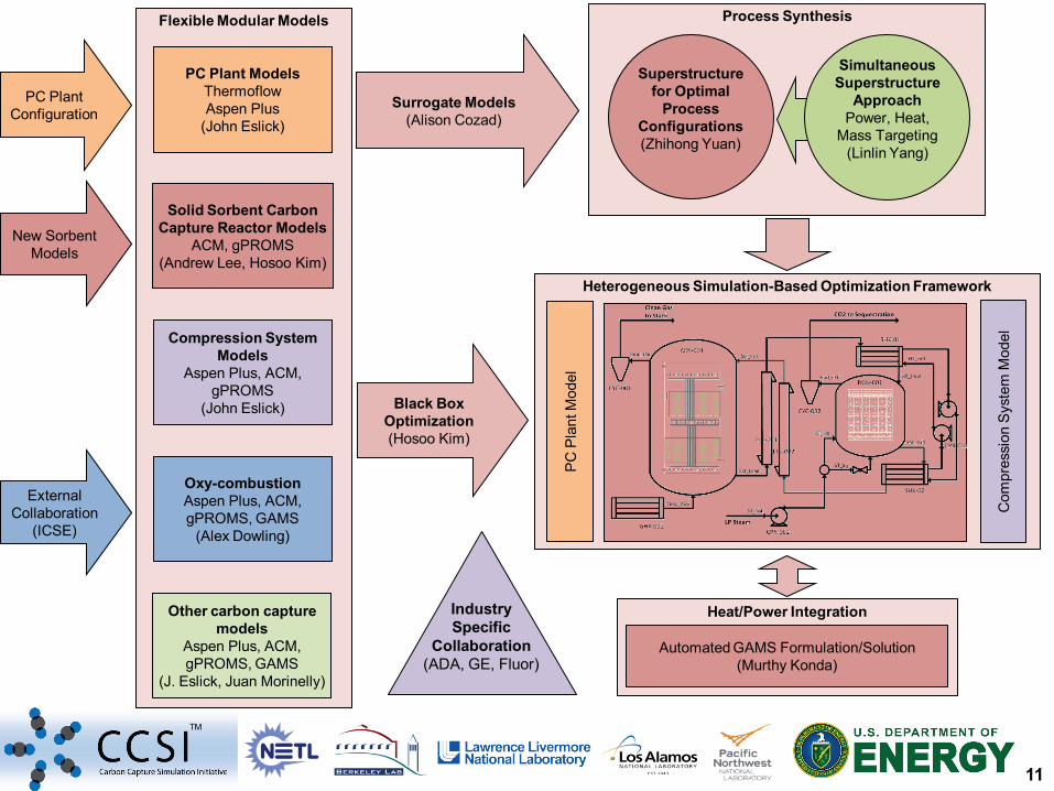
TM
Heterogeneous Simulation-Based Optimization Framework
PC
Pla
nt M
odel
Com
pres
sion
Sys
tem
Mod
el
Surrogate Models (Alison Cozad)
Heat/Power Integration
Automated GAMS Formulation/Solution (Murthy Konda)
Black Box Optimization (Hosoo Kim)
Process Synthesis
Superstructure for Optimal
Process Configurations (Zhihong Yuan)
Simultaneous Superstructure
Approach Power, Heat,
Mass Targeting (Linlin Yang)
PC Plant Configuration
New Sorbent Models
External Collaboration
(ICSE)
Industry Specific
Collaboration (ADA, GE, Fluor)
Flexible Modular Models
Solid Sorbent Carbon Capture Reactor Models
ACM, gPROMS (Andrew Lee, Hosoo Kim)
PC Plant Models Thermoflow Aspen Plus
(John Eslick)
Compression System Models
Aspen Plus, ACM, gPROMS
(John Eslick)
Oxy-combustion Aspen Plus, ACM, gPROMS, GAMS
(Alex Dowling)
Other carbon capture models
Aspen Plus, ACM, gPROMS, GAMS
(J. Eslick, Juan Morinelly)
12
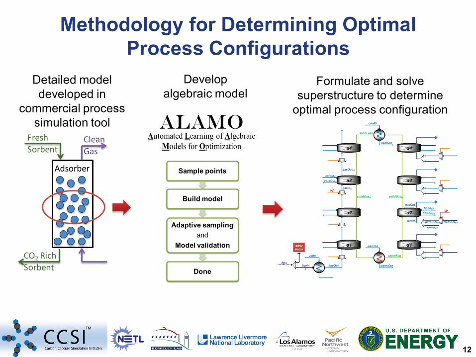
TM
Methodology for Determining Optimal Process Configurations
Detailed model developed in
commercial process simulation tool
Adsorber
CO2 Rich Sorbent
Fresh Sorbent
Clean Gas
Develop algebraic model
Formulate and solve superstructure to determine
optimal process configuration
Sample points
Build model
Adaptive sampling and
Model validation
Done
feedCO2d2
warmOut
coolOut
hotOutd2
coldIna3
coldOuta3
a4 d4
a2
a3
a1
d3
d1
d2
flueIn flueOut
solidOutd2
steamd2
pureCO2d2
hotInd2
gasInd2
gasOutd2
W
WsolidOuta3
gasOuta3
gasIna3
solidRich
solidLean
utilIn
coolIn
warmIn
…fgIn
othertrains
F
Automated Learning of Algebraic Models for Optimization
ALAMO
13
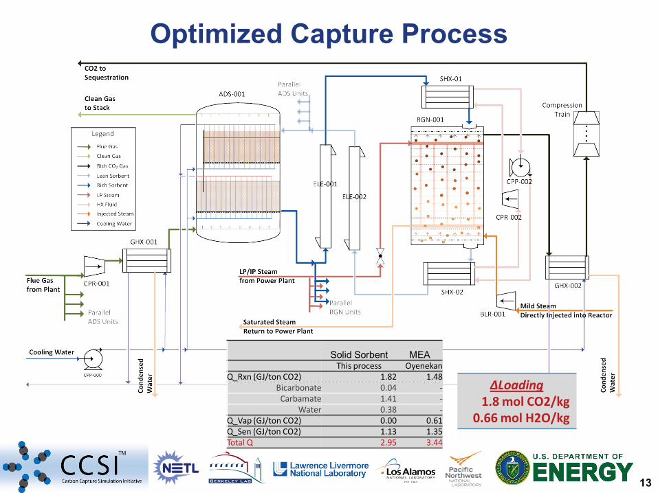
TM
Optimized Capture Process
∆Loading 1.8 mol CO2/kg
0.66 mol H2O/kg
Solid Sorbent MEA This process Oyenekan Q_Rxn (GJ/ton CO2) 1.82 1.48
Bicarbonate 0.04 - Carbamate 1.41 -
Water 0.38 - Q_Vap (GJ/ton CO2) 0.00 0.61 Q_Sen (GJ/ton CO2) 1.13 1.35 Total Q 2.95 3.44
14
TM
Inte
grat
ion
Fram
ewor
k
Basic Data
ROMs
UQ Framework
Risk Analysis & Decision Making Framework
Plant Operations & Control Tools and Models
Process Synthesis & Design Tools and Models
Particle & Device Scale
Simulation Tools and Models
15
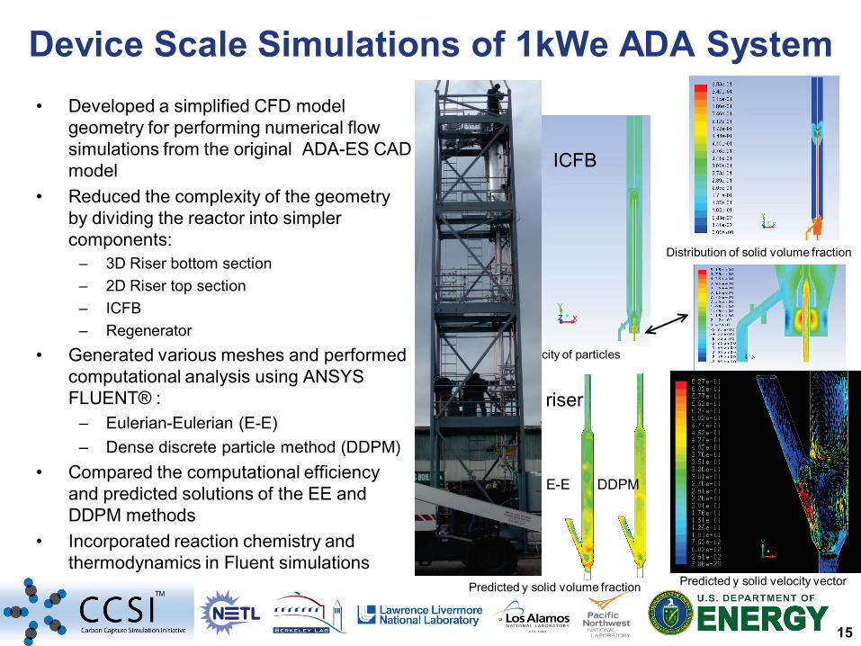
TM
• Developed a simplified CFD model geometry for performing numerical flow simulations from the original ADA-ES CAD model
• Reduced the complexity of the geometry by dividing the reactor into simpler components:
– 3D Riser bottom section – 2D Riser top section – ICFB – Regenerator
• Generated various meshes and performed computational analysis using ANSYS FLUENT® :
– Eulerian-Eulerian (E-E) – Dense discrete particle method (DDPM)
• Compared the computational efficiency and predicted solutions of the EE and DDPM methods
• Incorporated reaction chemistry and thermodynamics in Fluent simulations
Device Scale Simulations of 1kWe ADA System
Distribution of solid volume fraction
Predicted y velocity of particles
Predicted y solid volume fraction
E-E DDPM
Predicted y solid velocity vector
ICFB
riser
16
TM
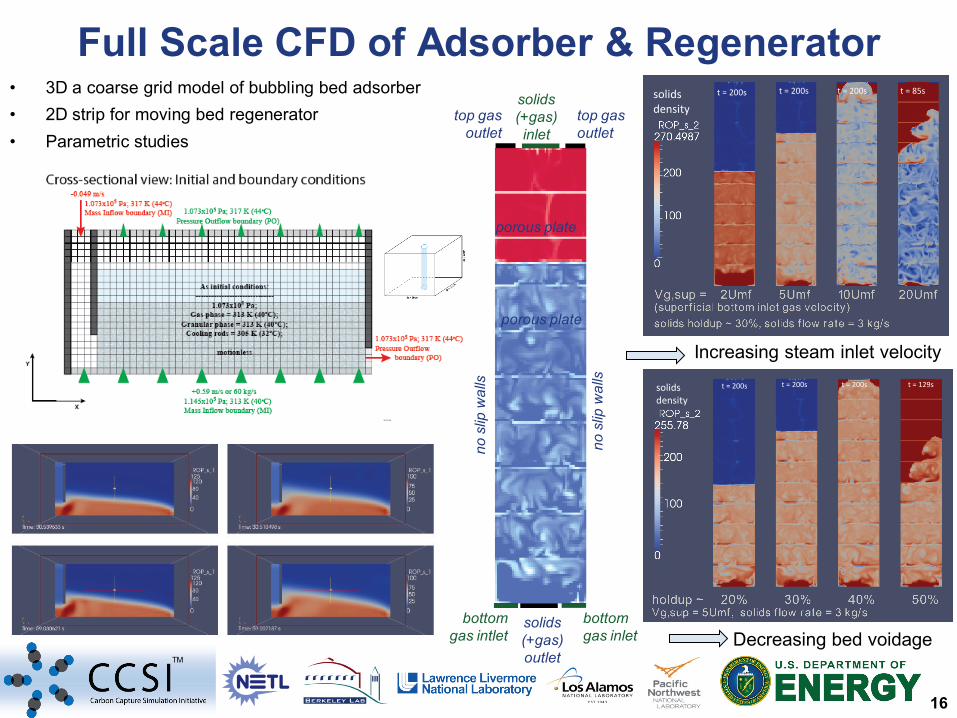
Full Scale CFD of Adsorber & Regenerator • 3D a coarse grid model of bubbling bed adsorber • 2D strip for moving bed regenerator • Parametric studies
top gas outlet
top gas outlet
solids (+gas) inlet
bottom gas inlet
bottom gas intlet
solids (+gas) outlet
no s
lip w
alls
no s
lip w
alls
porous plate
porous plate
solids density
t = 200s t = 200s t = 200s t = 129s
solids density
t = 200s t = 200s t = 200s t = 85s
Increasing steam inlet velocity
Decreasing bed voidage
17
TM
Inte
grat
ion
Fram
ewor
k
Basic Data
ROMs
UQ Framework
Risk Analysis & Decision Making Framework
Plant Operations & Control Tools and Models
Process Synthesis & Design Tools and Models
Particle & Device Scale
Simulation Tools and Models
18
TM
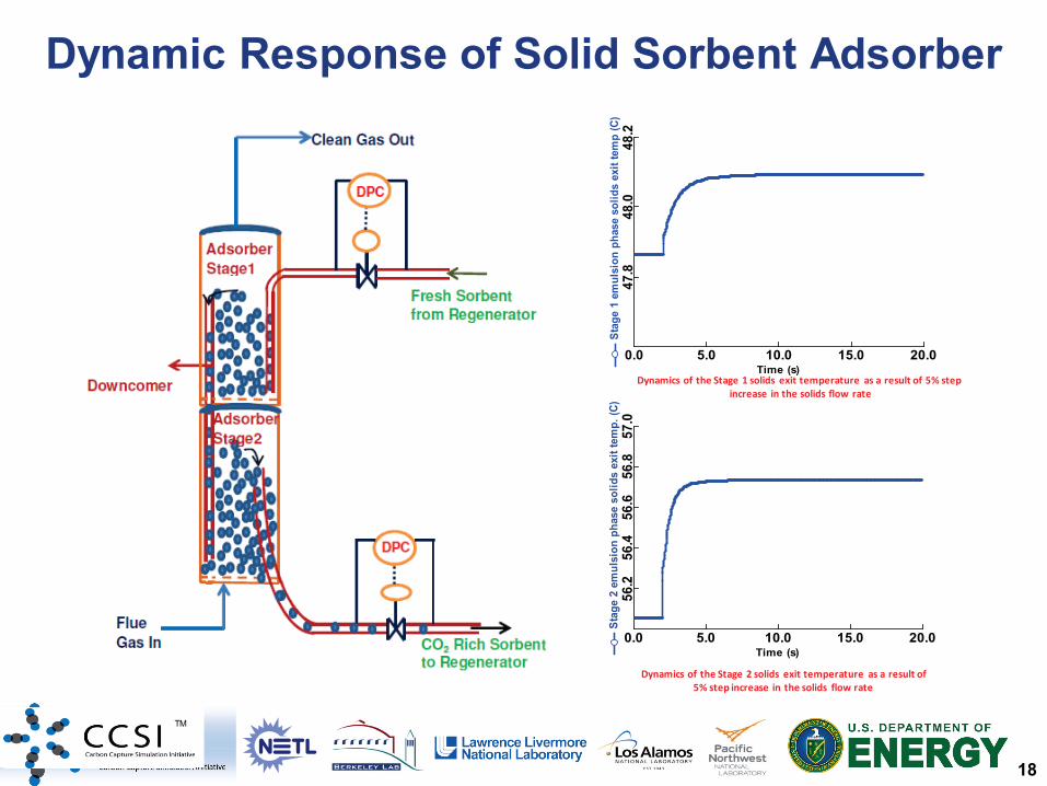
Dynamic Response of Solid Sorbent Adsorber
TM
Time (s)
Stag
e 1
emul
sion
pha
se s
olid
s ex
it te
mp
(C)
0.0 5.0 10.0 15.0 20.0
47.8
48.0
48.2
Dynamics of the Stage 1 solids exit temperature as a result of 5% stepincrease in the solids flow rate
Dynamics of the Stage 2 solids exit temperature as a result of 5% step increase in the solids flow rate
Time (s)
Stag
e 2
emul
sion
pha
se s
olid
s ex
it te
mp.
(C)
0.0 5.0 10.0 15.0 20.056
.256
.456
.656
.857
.0
19
TM
Inte
grat
ion
Fram
ewor
k
Basic Data
ROMs
UQ Framework
Risk Analysis & Decision Making Framework
Plant Operations & Control Tools and Models
Process Synthesis & Design Tools and Models
Particle & Device Scale
Simulation Tools and Models
20
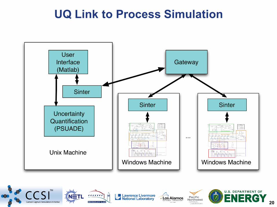
TM
UQ Link to Process Simulation
21
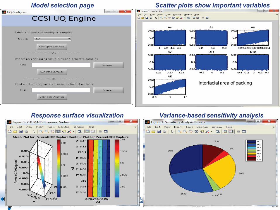
TM
Scatter plots show important variables
Response surface visualization Variance-based sensitivity analysis
Model selection page
Interfacial area of packing
22
TM
Inte
grat
ion
Fram
ewor
k
Basic Data
ROMs
UQ Framework
Risk Analysis & Decision Making Framework
Plant Operations & Control Tools and Models
Process Synthesis & Design Tools and Models
Particle & Device Scale
Simulation Tools and Models
23
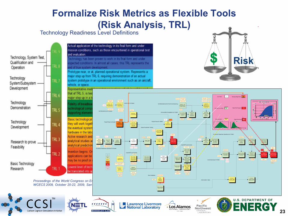
TM
Formalize Risk Metrics as Flexible Tools (Risk Analysis, TRL)
Proceedings of the World Congress on Engineering and Computer Science 2009 Vol II WCECS 2009, October 20-22, 2009, San Francisco, USA
Technology Readiness Level Definitions
$ Risk
DST-1
Low
Medium
High
Tune Accelerator3/2-3/31/06
Kicker Tests6/15-8/21/06
MediumHigh
Trim Cell PFNs & Inj Flat
-top Tune 4/3-4/26/06
Multi-Pulse Target Tests10/19/06-2/6/07
Tune DST for Target
8/22-10/18/06
MediumLow
DST-3, 7
DST-8A
DST-9
Complete
ACL-1A, 1B
ACL-2B
PFN Modifications11/1/05-1/24/06
Closed
DST-5,6, 8B, 9B
DR-1A, DST-2,4, DST-11,
ACL-3,4 ACL-5,6
MGT-2, DST-12
Cell Blocks & Connections 11/16/05-3/1/06
OPS-2A, 2B
OPS-3B,3C,4
Scaled Accelerator Testing
OPS-4, MGT-3B, DR-2
PFN-2PFN-1
Controls & Conf A
1/16/06-2/6/06
CNT-2, OPS-4
Install DST11/28/05-2/10/06
OPS-4, CNT-1A, DST-11-12, MGT-3B
Fab, Install, Test ConfC
Plus Controls6/1/06-8/21/06
Fab, Install, Test ConfB
Plus Controls3/3/06-6/15/06
INJ-5, CNT-1A, CNT-1B, OPS-4
LLNL Target Support (LOE)
6/1/06-2/6/07
DR-1A, PRG-4
DST-12
BCUZ Assemble &
Testing11/1-12/15/05
Beam Emit Tests
12/16/0-1/25/06
7.8 MHz Damping
1/26/06-2/23/06
DST-10
BCZ-1
ACL-4,6
INJ-8, OPS-4 INJ-7, 9
INJ-2
INJ-5
INJ-5 DR-1A
Cells 6 - 26 Refurbishment 11/16/05-2/21/06
PCR-1,PCR-4A,4B,5
PCR-2,7,8B
Maintain Controls (LOE)
6/15/06-2/6/07
MGT-3B
MGT-2
Cell Refurbishment for Scaled
Accelerator Readiness Operations for Scaled
Cells 27 - 65 Refurbishment 2/13/06-11/28/06
Injector & Balance Cell
Refurbishment 2/7/07-4/2/07
PCR-6
PCR-3
PCR-2,7,8B
PCR-1,PCR-4A,4B,5
Beam Parameter Map
at Target12/08/05
Injector Readiness &
Tune5/15-6/14/07
Accelerator Readiness Operations for 18 MeV
Accel Ops for BCUZ & Accel
(LOE)7/16-8/28/07
Pulsed Power for Scaled
Cell Refurbishment for Final Commissioning
Accel Ops for Kicker & Target
(LOE)8/29-11/20/07
Accel Ops for X-Ray Spot & Dose (LOE)
11/21/07-2/4/08
Assemble Injector Cells &
BCUZ4/5-4/18/07
Post Cell Block & Controls2/7-2/21/07
Cell Block & Intercell
Installations3/5-5/15/07
PCR-1,PCR-4A,4B,5
PCR-2,7,8B PCR-3
Cell and BCUZ Installation for 18 MeV
Install DST and Controls
Install Cells for Scaled
PFN Modifications5/1/06-8/16/06
Pulsed Power for 18MeV
PFN-2
PFN Parts12/1/05-9/29/06
Trim Accel Cell PFNs, Flat-top
Tune Marx6/15-7/13/07
Accel Tune for Full Energy7/16-7/27/07
Beam to Dump Commissioning
8/1-8/14/07
Kicker and Transport
Commissioning8/14-10/11/07
Commissioning for 18 MeV
Target Commissioning
10/11-12/3/07
X-Ray Spot & Dose - 4 Pulses
12/4/07-2/7/08
DST-8BDST- 9B
Install, Verify Kicker; Accel
Controls2/7-3/7/07
Install & Verify BN Shield 3/8-3/21/07
CNT-1A
Install DST and Controls
CNT-1A
OPS-3B,C
Door Installation
Window8/1/06-10/31/06
Door Installation DR1B, OPS-4
BDR-1BDR-1, PRG-3,
PRG-1A
DST-1
MGT-2,DST-12
DST-12DST-1
BDR-1
CAM-1
BCZ-1
CNT-2
CNT-2
CNT-2
CNT-2
CNT-1A, PRG-4
CNT-2
CNT-2
CNT-2
CNT-2
INJ-5ACL-2B
PFN-1
INJ-6,7, 9
INJ-4
INJ-3,6,7, 9
CNT-2
Authorization Basis
MSA Activities10/2/06-2/12/07
Conduct Phase I ARR2/13/07-4/30/07
Conduct Phase II ARR
8/6/07-8/31/07
CNT-2
OPS-6
DR-3
MGT-4A
MGT-4A
Install Target & Laser, Verify
Controls 4/9-4/20/07
Install & Verify Beamstop,
Septum,Quads & Controls 3/22-4/6/07
Target Controls 3/8-3/21/07
PRG-1B
CNT-2
INJ-3,6,7, 9
ACL-1A, 1B ACL-3,4
ACL-5,6
Medium Risk
Medium Low Risk
Low Risk Medium High Risk
High Risk Regular
High Risk Special
24
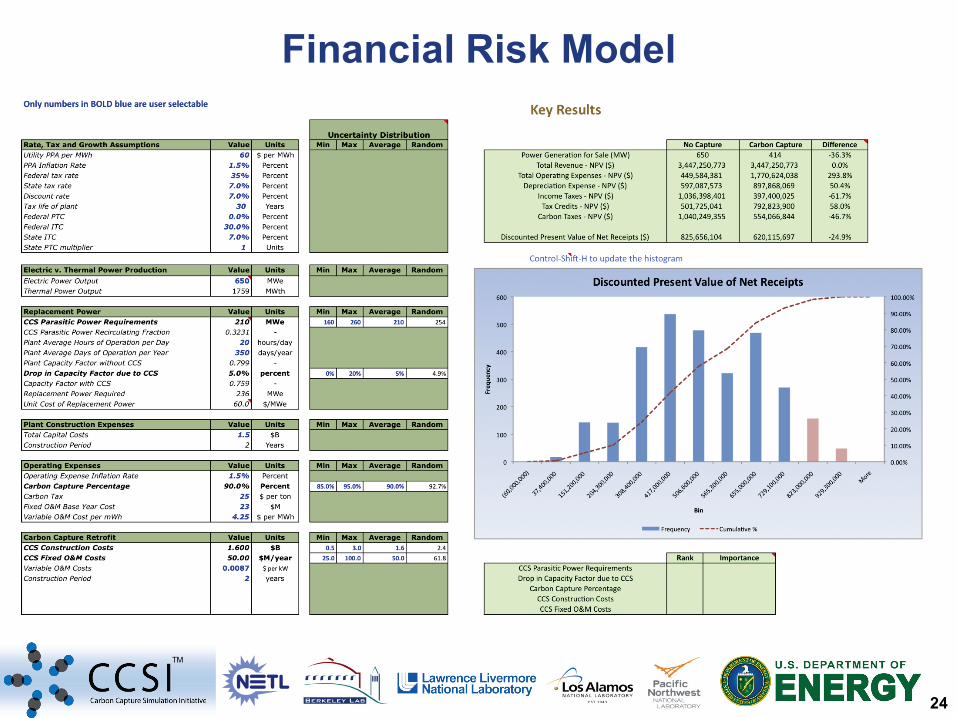
TM
Financial Risk Model
25
TM
Inte
grat
ion
Fram
ewor
k
Basic Data
ROMs
UQ Framework
Risk Analysis & Decision Making Framework
Plant Operations & Control Tools and Models
Process Synthesis & Design Tools and Models
Particle & Device Scale
Simulation Tools and Models
26
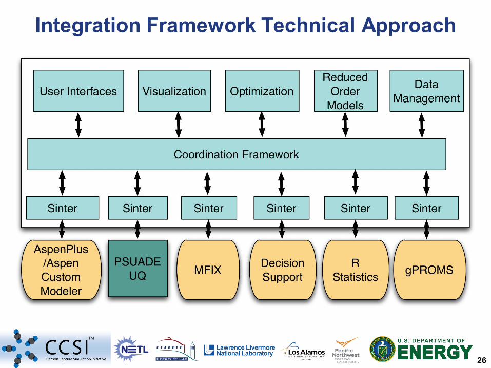
TM
Integration Framework Technical Approach
27
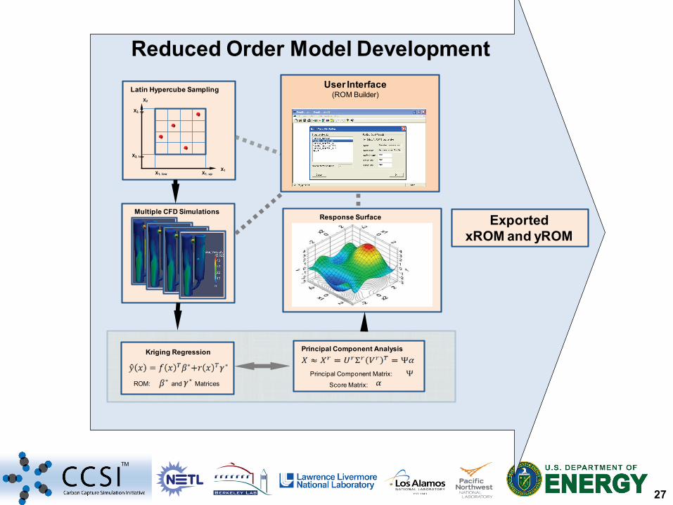
TM
Reduced Order Model Development
Response Surface
Latin Hypercube Sampling
X1, low X1, up
X2, up
X2, low
X1
X2
Multiple CFD Simulations
Kriging Regression
ROM: and Matrices
Principal Component Analysis
Principal Component Matrix:
Score Matrix:
User Interface(ROM Builder)
ExportedxROM and yROM
28
TM
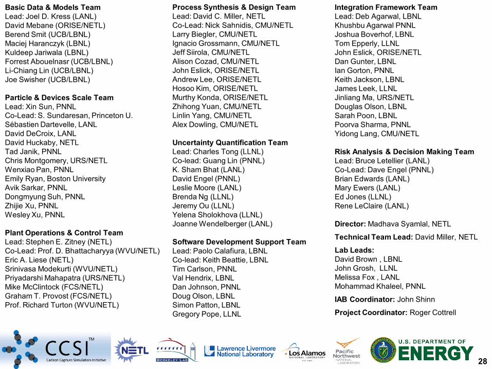
Process Synthesis & Design Team Lead: David C. Miller, NETL Co-Lead: Nick Sahnidis, CMU/NETL Larry Biegler, CMU/NETL Ignacio Grossmann, CMU/NETL Jeff Siirola, CMU/NETL Alison Cozad, CMU/NETL John Eslick, ORISE/NETL Andrew Lee, ORISE/NETL Hosoo Kim, ORISE/NETL Murthy Konda, ORISE/NETL Zhihong Yuan, CMU/NETL Linlin Yang, CMU/NETL Alex Dowling, CMU/NETL Uncertainty Quantification Team Lead: Charles Tong (LLNL) Co-lead: Guang Lin (PNNL) K. Sham Bhat (LANL) David Engel (PNNL) Leslie Moore (LANL) Brenda Ng (LLNL) Jeremy Ou (LLNL) Yelena Sholokhova (LLNL) Joanne Wendelberger (LANL) Software Development Support Team Lead: Paolo Calafiura, LBNL Co-lead: Keith Beattie, LBNL Tim Carlson, PNNL Val Hendrix, LBNL Dan Johnson, PNNL Doug Olson, LBNL Simon Patton, LBNL Gregory Pope, LLNL
Integration Framework Team Lead: Deb Agarwal, LBNL Khushbu Agarwal PNNL Joshua Boverhof, LBNL Tom Epperly, LLNL John Eslick, ORISE/NETL Dan Gunter, LBNL Ian Gorton, PNNL Keith Jackson, LBNL James Leek, LLNL Jinliang Ma, URS/NETL Douglas Olson, LBNL Sarah Poon, LBNL Poorva Sharma, PNNL Yidong Lang, CMU/NETL Risk Analysis & Decision Making Team Lead: Bruce Letellier (LANL) Co-Lead: Dave Engel (PNNL) Brian Edwards (LANL) Mary Ewers (LANL) Ed Jones (LLNL) Rene LeClaire (LANL) Director: Madhava Syamlal, NETL
Technical Team Lead: David Miller, NETL
Lab Leads: David Brown , LBNL John Grosh, LLNL Melissa Fox , LANL Mohammad Khaleel, PNNL
IAB Coordinator: John Shinn
Project Coordinator: Roger Cottrell
Basic Data & Models Team Lead: Joel D. Kress (LANL) David Mebane (ORISE/NETL) Berend Smit (UCB/LBNL) Maciej Haranczyk (LBNL) Kuldeep Jariwala (LBNL) Forrest Abouelnasr (UCB/LBNL) Li-Chiang Lin (UCB/LBNL) Joe Swisher (UCB/LBNL) Particle & Devices Scale Team Lead: Xin Sun, PNNL Co-Lead: S. Sundaresan, Princeton U. Sébastien Dartevelle, LANL David DeCroix, LANL David Huckaby, NETL Tad Janik, PNNL Chris Montgomery, URS/NETL Wenxiao Pan, PNNL Emily Ryan, Boston University Avik Sarkar, PNNL Dongmyung Suh, PNNL Zhijie Xu, PNNL Wesley Xu, PNNL Plant Operations & Control Team Lead: Stephen E. Zitney (NETL) Co-Lead: Prof. D. Bhattacharyya (WVU/NETL) Eric A. Liese (NETL) Srinivasa Modekurti (WVU/NETL) Priyadarshi Mahapatra (URS/NETL) Mike McClintock (FCS/NETL) Graham T. Provost (FCS/NETL) Prof. Richard Turton (WVU/NETL)
29
TM
This presentation was prepared as an account of work sponsored by an agency of the United States Government. Neither the United States Government nor any agency thereof, nor any of their employees, makes any warranty, express or implied, or assumes any legal liability or responsibility for the accuracy, completeness, or usefulness of any information, apparatus, product, or process disclosed, or represents that its use would not infringe privately owned rights. Reference herein to any specific commercial product, process, or service by trade name, trademark, manufacturer, or otherwise does not necessarily constitute or imply its endorsement, recommendation, or favoring by the United States Government or any agency thereof. The views and opinions of authors expressed herein do not necessarily state or reflect those of the United States Government or any agency thereof.
Disclaimer


![ESI[tronic] 2.0 Updates Highlights ESI[tronic] 2.0 vehicle ...upm.bosch.com/News/2018_3/ESI_News_2018-3_en.pdf · Complete ESI[tronic] 2.0 as an online download Use ESI[tronic] 2.0](https://static.fdocuments.in/doc/165x107/5c5e113b09d3f2ca618bb3cd/esitronic-20-updates-highlights-esitronic-20-vehicle-upmboschcomnews20183esinews2018-3enpdf.jpg)


![Highlights of ESI[truck] North America ESI[truck] North ...](https://static.fdocuments.in/doc/165x107/628b4a9ff91dad22754155f1/highlights-of-esitruck-north-america-esitruck-north-.jpg)