TL2.28 Aircraft equipment for an LAA Permit Aircraft ... · TL 2.28 Night IFR assessment Issue 2...
31
TL 2.28 Night IFR assessment Issue 2 Page 1 of 31 TL 2.28 Iss2 November 2018 Assessment of LAA Permit to Fly Aircraft for Operation in IMC, Under IFR or at Night INTRODUCTION TL 2.27 provides guidance on how to apply for clearance to night and/or IMC or IFR flight on an LAA aircraft. The aim of this Technical Leaflet TL 2.28 is to, - Describe the equipment required for night and/or IMC or IFR operation, - To provide some background to these requirement, - To enable owners to document how their aeroplane complies with the rules, - To provide guidance on how the documentation should be completed. Use the forms in this TL to provide the data to support your application for the removal of the Day/VMC limitation from your aeroplane. In the sections below the rules are presented, with the rationale for the rule. As experience is gained example methods of complying with the rules will be included at the end of each section. There are very likely to be other methods of compliance with the rules. In general owners of previously type certificated (PTC) aeroplanes, that is aeroplanes that have previously held a certificate of airworthiness that permitted flight in IMC and/or at night, are likely to find this process straight forward as long as their aeroplanes have not been modified too far from the original certified configuration. Owners of amateur built aircraft may find some of the rules more challenging to comply with. RESPONSIBILITY FOR PROVIDING INFORMATION It is the owner’s responsibility to provide sufficient information to demonstrate to the LAA that the rules in this TL have been met. In the first instance the owner must be certain in his/her own mind that the aircraft is suitably equipped for the type of operation intended. BASIS FOR THESE RULES To define the rules contained in this Technical Leaflet, all of the relevant requirements of EASA Certification Standard CS23 and the ANO have been examined individually by the LAA to assess whether they should be met by LAA aircraft seeking a night/IFR clearance, and if so, how compliance might be demonstrated to an appropriate level for a non-certified aircraft. These documents, and in some cases LAA policy, describe functionality that must be present in an LAA aircraft. These become ‘required functions’ for the purposes of removing day/VFR restrictions. The LAA has conducted several in-depth analyses to determine where latitude should be allowed against the strict requirements of CS23 and the ANO. One of the major concessions is that non- certified equipment may be used in most cases. Owners who wish to install equipment that does not meet the rules described here must provide a robust and detailed technical argument explaining how the hazards of instrument and night flight are mitigated by their chosen installation. The LAA will examine any proposals submitted, but this will inevitably take longer and cost more than following what is written here, with no guarantee of success. Any owner who wishes to investigate this route should show how their proposed installation meets each paragraph of CS23 and provide evidence to substantiate their claim.
Transcript of TL2.28 Aircraft equipment for an LAA Permit Aircraft ... · TL 2.28 Night IFR assessment Issue 2...
TL 2.28 Night IFR assessment Issue 2 Page 1 of 31
TL 2.28 Iss2 November 2018 Assessment of LAA Permit to Fly Aircraft for Operation in IMC, Under IFR or at Night INTRODUCTION TL 2.27 provides guidance on how to apply for clearance to night and/or IMC or IFR flight on an LAA aircraft. The aim of this Technical Leaflet TL 2.28 is to,
- Describe the equipment required for night and/or IMC or IFR operation, - To provide some background to these requirement, - To enable owners to document how their aeroplane complies with the rules, - To provide guidance on how the documentation should be completed.
Use the forms in this TL to provide the data to support your application for the removal of the Day/VMC limitation from your aeroplane. In the sections below the rules are presented, with the rationale for the rule. As experience is gained example methods of complying with the rules will be included at the end of each section. There are very likely to be other methods of compliance with the rules. In general owners of previously type certificated (PTC) aeroplanes, that is aeroplanes that have previously held a certificate of airworthiness that permitted flight in IMC and/or at night, are likely to find this process straight forward as long as their aeroplanes have not been modified too far from the original certified configuration. Owners of amateur built aircraft may find some of the rules more challenging to comply with. RESPONSIBILITY FOR PROVIDING INFORMATION It is the owner’s responsibility to provide sufficient information to demonstrate to the LAA that the rules in this TL have been met. In the first instance the owner must be certain in his/her own mind that the aircraft is suitably equipped for the type of operation intended. BASIS FOR THESE RULES To define the rules contained in this Technical Leaflet, all of the relevant requirements of EASA Certification Standard CS23 and the ANO have been examined individually by the LAA to assess whether they should be met by LAA aircraft seeking a night/IFR clearance, and if so, how compliance might be demonstrated to an appropriate level for a non-certified aircraft. These documents, and in some cases LAA policy, describe functionality that must be present in an LAA aircraft. These become ‘required functions’ for the purposes of removing day/VFR restrictions. The LAA has conducted several in-depth analyses to determine where latitude should be allowed against the strict requirements of CS23 and the ANO. One of the major concessions is that non-certified equipment may be used in most cases. Owners who wish to install equipment that does not meet the rules described here must provide a robust and detailed technical argument explaining how the hazards of instrument and night flight are mitigated by their chosen installation. The LAA will examine any proposals submitted, but this will inevitably take longer and cost more than following what is written here, with no guarantee of success. Any owner who wishes to investigate this route should show how their proposed installation meets each paragraph of CS23 and provide evidence to substantiate their claim.
TL 2.28 Night IFR assessment Issue 2 Page 2 of 31
Any owner may take an alternative route of establishing a compliance statement against CS 23 and the ANO and submit this to the LAA, but again this is likely to be more tortuous and expensive. CONVENTIONAL AND COMPLEX EQUIPMENT In this TL equipment is described as either ‘conventional’ or ‘complex’. Conventional equipment is typically a single purpose device that uses mechanical, electrical or analogue electronic components to perform its function. The failure modes of these devices are often discernable from a detailed inspection. These devices are generally acceptable to the LAA to carry out a required function. Complex equipment typically uses digital electronics and software to carry out its function. Its failure modes are usually not clear and little can be discerned from a detailed inspection, particularly for software intensive systems. These systems require that their makers use sound practices during design and manufacture to ensure the system has a long and reliable life. The LAA must be given evidence that such systems are appropriate to carry out the intended function. This is straightforward where the manufacturer can demonstrate such systems have been designed and built to appropriate industry standards. Where little evidence is available that the industry standards have been followed – as is the case with most equipment built for un-certified aircraft – LAA acceptance becomes more difficult. Modern electronics are often much more reliable than their mechanical or analogue forebears, but require skilled and experienced designers to be successful in the airborne environment. The LAA typically require that such equipment has a track history of reliable operation and is either,
- single purpose equipment that can be directly switched off if it should malfunction, - carries out a function that is not essential for flight or - where it performs a required function, it must be provided with a backup.
Complex equipment is often costly; when choosing equipment for installation in an aircraft that is intended for night or IMC operation owners are advised to either choose equipment listed in Annex A of this TL or to contact LAA Engineering to discuss their intentions before purchase. Retrospective clearance of equipment, or obtaining data from manufacturers, is often much more difficult than addressing the issue before purchase. CERTIFIED OR APPROVED, UN-CERTIFIED OR UN-APPROVED? For aircraft with Certificates of Airworthiness, all of the installed equipment must function to defined certification specifications, be manufactured to defined standards and to be installed in a prescribed manner as part of a certified system. It is an arrangement that underpins the aircraft type-certification process that results in individual aircraft being issued with a Certificate of Airworthiness and intended to ensure that each component is known and documented and will deliver adequate reliability. Such equipment is certified by the manufacturer as meeting appropriate requirements and approved by the National Aviation Authority for use in an aircraft holding a Certificate of Airworthiness. By definition, equipment which does not fulfil these requirements is un-certified and thus un-approved for such use. Within this Technical Leaflet the terms ‘un-certified’ or ‘un-approved’ refer to commercially produced equipment that is neither formally certified by the manufacturer nor approved by an NAA for aeronautical use. The term ‘un-approved’ is used in preference to ‘un-certified’, as this avoids
TL 2.28 Night IFR assessment Issue 2 Page 3 of 31
ambiguity in respect of equipment which is ‘certified’ by a manufacturer but ‘un-approved’ by an NAA. Certified and approved equipment will be supplied with an EASA Form 1, or an equivalent such as an FAA 8130-3. If no Form 1 accompanies the part then it is un-approved. Once assessed and accepted by the LAA, the instrument and equipment fit becomes ‘approved’ as required by the 2016 issue of the ANO. SUITABILITY OF CERTIFIED OR APPROVED EQUIPMENT Owners are cautioned that just because an item of equipment is supplied with a Form 1 does not mean that it is suitable for their application. For example, an autopilot approved for a Piper Warrior is unlikely to be suitable for a Lancair. Owners must assess each part to compare the certified application against their intended usage. Advice from an inspector or from LAA Engineering should be obtained where any uncertainty exists. INDIVIDUAL AIRCRAFT ASSESSMENT In assessing an application for the removal of the Day VMC operating limitation, the LAA has to consider 6 aspects:
- Aircraft Reliability - Airframe and Powerplant - Instrumentation - Electrical System - Night Flying equipment - Similarity of this particular aircraft to the first of type cleared
The owner must show that the aircraft complies with the rules in the sections below. Each rule is numbered to allow easy cross-referencing. Some rules have examples that are likely to be acceptable – but these are by no means the only methods of complying. The rationale behind each rule is also provided to enable owners to understand what is required should they wish to propose a different compliance method. Owners who are applying only for night flying only should read section 5. Any modifications that may impact the flying qualities of the aircraft may mean that a further flight evaluation is required, at the discretion of LAA Engineering. PREVIOUSLY TYPE CERTIFIED AIRCRAFT PTC aircraft owners will find that the rules in this TL are focused on homebuilt aircraft. Where reference is made to published data from the POH or maintenance manual a full reference should be provided along with a scan of the relevant section, or the relevant document should be provided to the assessor. THE TECHNICAL STANDARDS TO BE MET The following pages contain the rules that shall be met by LAA Permit to Fly Aircraft if the Day VMC operating limitation is to be removed. These are broken down into:
• Demonstration of Aircraft Reliability, rules 1.1.1 to 1.1.2 • Powerplant Rules, rules 1.2.1 to 1.2.6 • Instrument Rules, rules 1.3.1 to 1.3.15 • Electrical System Rules, rules 2.1. to 2.8 • Night Flying Rules, rules 3.1 to 3.10
TL 2.28 Night IFR assessment Issue 2 Page 4 of 31
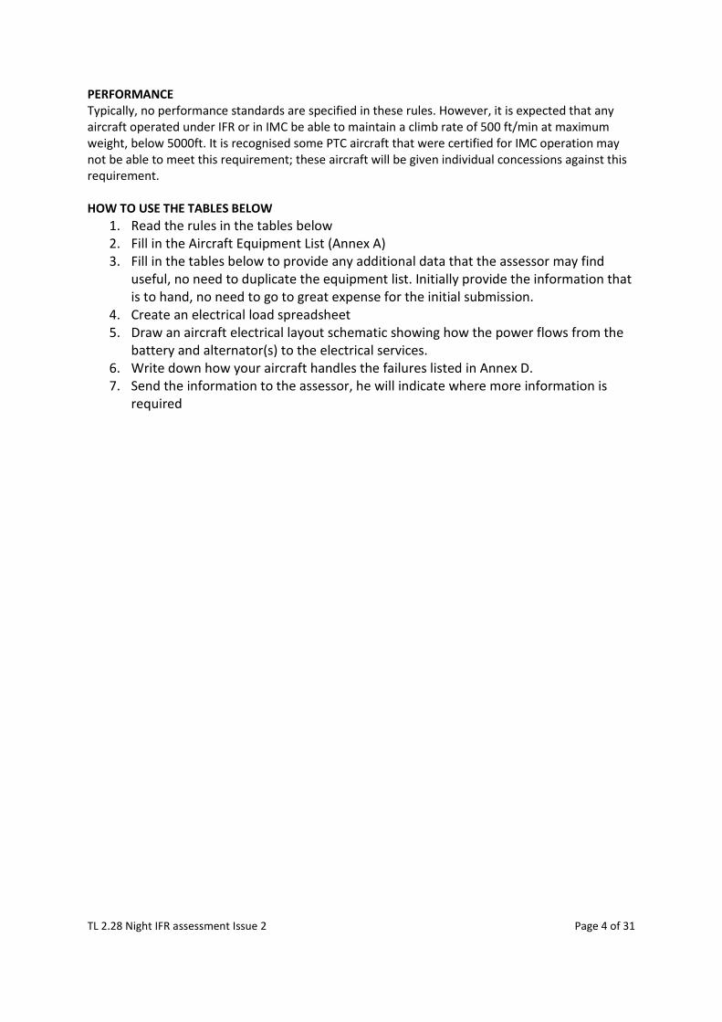
PERFORMANCE Typically, no performance standards are specified in these rules. However, it is expected that any aircraft operated under IFR or in IMC be able to maintain a climb rate of 500 ft/min at maximum weight, below 5000ft. It is recognised some PTC aircraft that were certified for IMC operation may not be able to meet this requirement; these aircraft will be given individual concessions against this requirement. HOW TO USE THE TABLES BELOW
1. Read the rules in the tables below 2. Fill in the Aircraft Equipment List (Annex A) 3. Fill in the tables below to provide any additional data that the assessor may find
useful, no need to duplicate the equipment list. Initially provide the information that is to hand, no need to go to great expense for the initial submission.
4. Create an electrical load spreadsheet 5. Draw an aircraft electrical layout schematic showing how the power flows from the
battery and alternator(s) to the electrical services. 6. Write down how your aircraft handles the failures listed in Annex D. 7. Send the information to the assessor, he will indicate where more information is
required
TL 2.28 Night IFR assessment Issue 2 Page 5 of 31
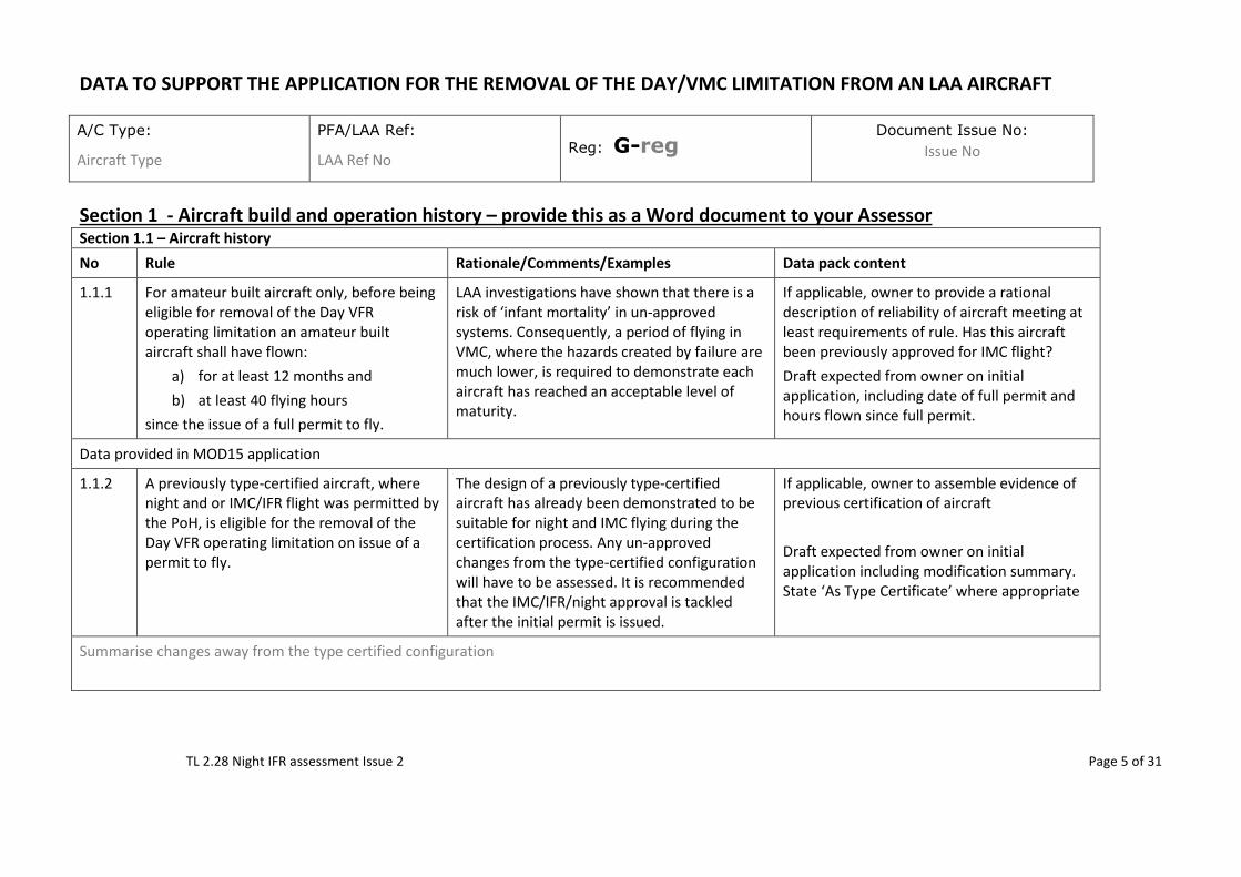
DATA TO SUPPORT THE APPLICATION FOR THE REMOVAL OF THE DAY/VMC LIMITATION FROM AN LAA AIRCRAFT A/C Type:
Aircraft Type
PFA/LAA Ref:
LAA Ref No Reg: G-reg
Document Issue No: Issue No
Section 1 - Aircraft build and operation history – provide this as a Word document to your Assessor Section 1.1 – Aircraft history No Rule Rationale/Comments/Examples Data pack content
1.1.1 For amateur built aircraft only, before being eligible for removal of the Day VFR operating limitation an amateur built aircraft shall have flown:
a) for at least 12 months and b) at least 40 flying hours
since the issue of a full permit to fly.
LAA investigations have shown that there is a risk of ‘infant mortality’ in un-approved systems. Consequently, a period of flying in VMC, where the hazards created by failure are much lower, is required to demonstrate each aircraft has reached an acceptable level of maturity.
If applicable, owner to provide a rational description of reliability of aircraft meeting at least requirements of rule. Has this aircraft been previously approved for IMC flight? Draft expected from owner on initial application, including date of full permit and hours flown since full permit.
Data provided in MOD15 application
1.1.2 A previously type-certified aircraft, where night and or IMC/IFR flight was permitted by the PoH, is eligible for the removal of the Day VFR operating limitation on issue of a permit to fly.
The design of a previously type-certified aircraft has already been demonstrated to be suitable for night and IMC flying during the certification process. Any un-approved changes from the type-certified configuration will have to be assessed. It is recommended that the IMC/IFR/night approval is tackled after the initial permit is issued.
If applicable, owner to assemble evidence of previous certification of aircraft Draft expected from owner on initial application including modification summary. State ‘As Type Certificate’ where appropriate
Summarise changes away from the type certified configuration
TL 2.28 Night IFR assessment Issue 2 Page 6 of 31
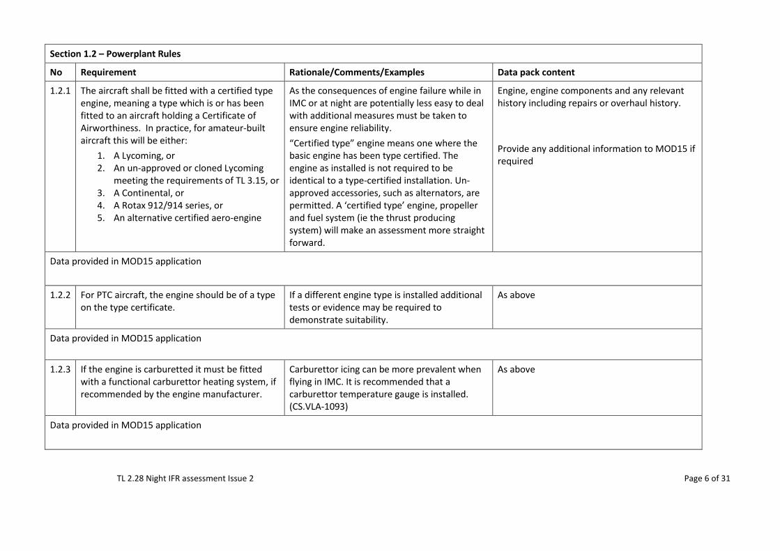
Section 1.2 – Powerplant Rules
No Requirement Rationale/Comments/Examples Data pack content
1.2.1 The aircraft shall be fitted with a certified type engine, meaning a type which is or has been fitted to an aircraft holding a Certificate of Airworthiness. In practice, for amateur-built aircraft this will be either:
1. A Lycoming, or 2. An un-approved or cloned Lycoming
meeting the requirements of TL 3.15, or 3. A Continental, or 4. A Rotax 912/914 series, or 5. An alternative certified aero-engine
As the consequences of engine failure while in IMC or at night are potentially less easy to deal with additional measures must be taken to ensure engine reliability. “Certified type” engine means one where the basic engine has been type certified. The engine as installed is not required to be identical to a type-certified installation. Un-approved accessories, such as alternators, are permitted. A ‘certified type’ engine, propeller and fuel system (ie the thrust producing system) will make an assessment more straight forward.
Engine, engine components and any relevant history including repairs or overhaul history. Provide any additional information to MOD15 if required
Data provided in MOD15 application
1.2.2 For PTC aircraft, the engine should be of a type on the type certificate.
If a different engine type is installed additional tests or evidence may be required to demonstrate suitability.
As above
Data provided in MOD15 application
1.2.3 If the engine is carburetted it must be fitted with a functional carburettor heating system, if recommended by the engine manufacturer.
Carburettor icing can be more prevalent when flying in IMC. It is recommended that a carburettor temperature gauge is installed. (CS.VLA-1093)
As above
Data provided in MOD15 application
TL 2.28 Night IFR assessment Issue 2 Page 7 of 31
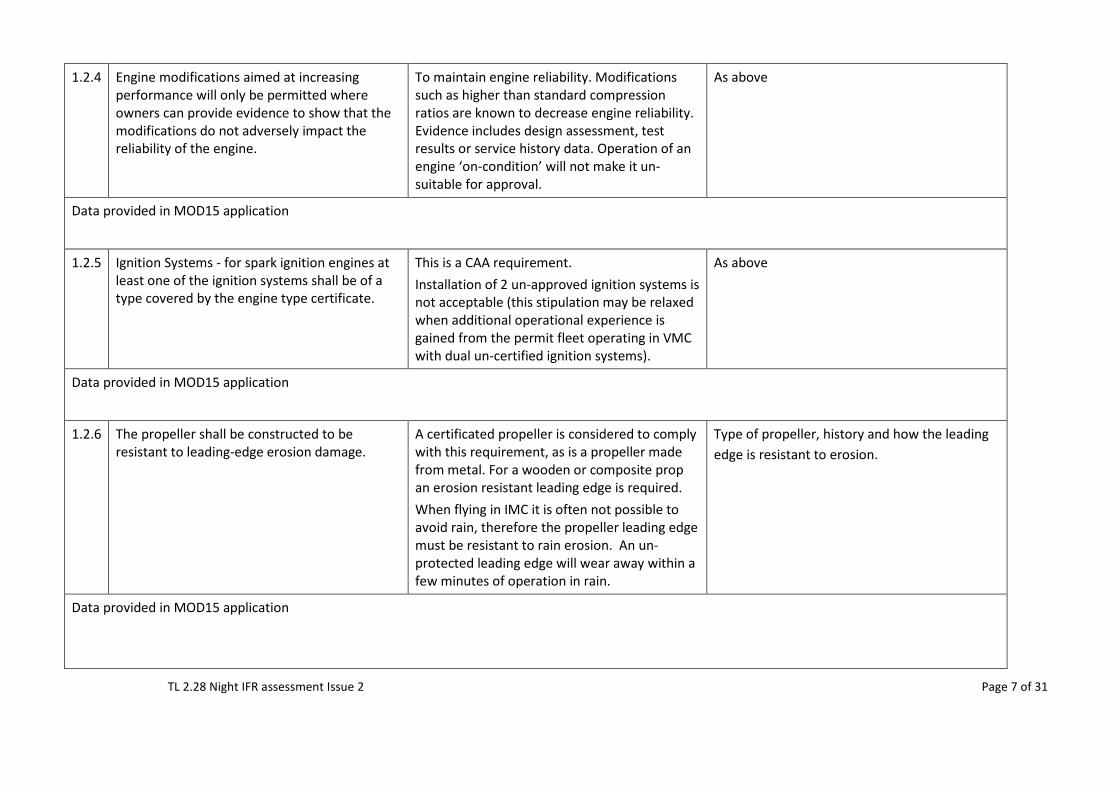
1.2.4 Engine modifications aimed at increasing performance will only be permitted where owners can provide evidence to show that the modifications do not adversely impact the reliability of the engine.
To maintain engine reliability. Modifications such as higher than standard compression ratios are known to decrease engine reliability. Evidence includes design assessment, test results or service history data. Operation of an engine ‘on-condition’ will not make it un-suitable for approval.
As above
Data provided in MOD15 application
1.2.5 Ignition Systems - for spark ignition engines at least one of the ignition systems shall be of a type covered by the engine type certificate.
This is a CAA requirement. Installation of 2 un-approved ignition systems is not acceptable (this stipulation may be relaxed when additional operational experience is gained from the permit fleet operating in VMC with dual un-certified ignition systems).
As above
Data provided in MOD15 application
1.2.6 The propeller shall be constructed to be resistant to leading-edge erosion damage.
A certificated propeller is considered to comply with this requirement, as is a propeller made from metal. For a wooden or composite prop an erosion resistant leading edge is required. When flying in IMC it is often not possible to avoid rain, therefore the propeller leading edge must be resistant to rain erosion. An un-protected leading edge will wear away within a few minutes of operation in rain.
Type of propeller, history and how the leading edge is resistant to erosion.
Data provided in MOD15 application
TL 2.28 Night IFR assessment Issue 2 Page 8 of 31
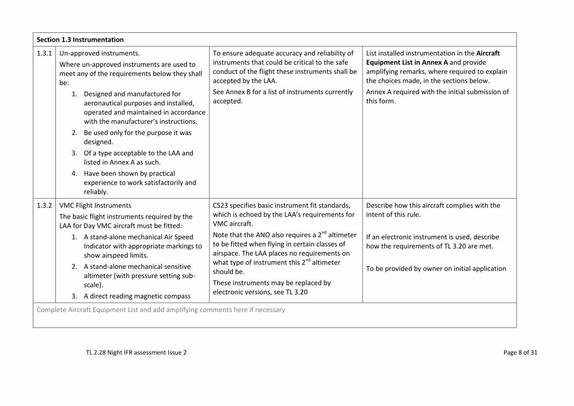
Section 1.3 Instrumentation
1.3.1 Un-approved instruments. Where un-approved instruments are used to meet any of the requirements below they shall be:
1. Designed and manufactured for aeronautical purposes and installed, operated and maintained in accordance with the manufacturer’s instructions.
2. Be used only for the purpose it was designed.
3. Of a type acceptable to the LAA and listed in Annex A as such.
4. Have been shown by practical experience to work satisfactorily and reliably.
To ensure adequate accuracy and reliability of instruments that could be critical to the safe conduct of the flight these instruments shall be accepted by the LAA. See Annex B for a list of instruments currently accepted.
List installed instrumentation in the Aircraft Equipment List in Annex A and provide amplifying remarks, where required to explain the choices made, in the sections below. Annex A required with the initial submission of this form.
1.3.2 VMC Flight Instruments The basic flight instruments required by the LAA for Day VMC aircraft must be fitted:
1. A stand-alone mechanical Air Speed Indicator with appropriate markings to show airspeed limits.
2. A stand-alone mechanical sensitive altimeter (with pressure setting sub-scale).
3. A direct reading magnetic compass
CS23 specifies basic instrument fit standards, which is echoed by the LAA’s requirements for VMC aircraft. Note that the ANO also requires a 2nd altimeter to be fitted when flying in certain classes of airspace. The LAA places no requirements on what type of instrument this 2nd altimeter should be. These instruments may be replaced by electronic versions, see TL 3.20
Describe how this aircraft complies with the intent of this rule. If an electronic instrument is used, describe how the requirements of TL 3.20 are met. To be provided by owner on initial application
Complete Aircraft Equipment List and add amplifying comments here if necessary
TL 2.28 Night IFR assessment Issue 2 Page 9 of 31
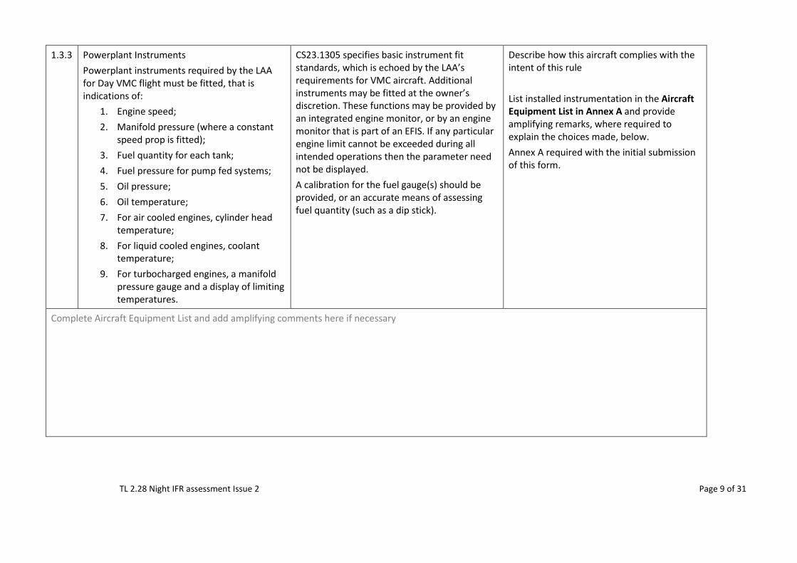
1.3.3 Powerplant Instruments Powerplant instruments required by the LAA for Day VMC flight must be fitted, that is indications of:
1. Engine speed; 2. Manifold pressure (where a constant
speed prop is fitted); 3. Fuel quantity for each tank; 4. Fuel pressure for pump fed systems; 5. Oil pressure; 6. Oil temperature; 7. For air cooled engines, cylinder head
temperature; 8. For liquid cooled engines, coolant
temperature; 9. For turbocharged engines, a manifold
pressure gauge and a display of limiting temperatures.
CS23.1305 specifies basic instrument fit standards, which is echoed by the LAA’s requirements for VMC aircraft. Additional instruments may be fitted at the owner’s discretion. These functions may be provided by an integrated engine monitor, or by an engine monitor that is part of an EFIS. If any particular engine limit cannot be exceeded during all intended operations then the parameter need not be displayed. A calibration for the fuel gauge(s) should be provided, or an accurate means of assessing fuel quantity (such as a dip stick).
Describe how this aircraft complies with the intent of this rule List installed instrumentation in the Aircraft Equipment List in Annex A and provide amplifying remarks, where required to explain the choices made, below. Annex A required with the initial submission of this form.
Complete Aircraft Equipment List and add amplifying comments here if necessary
TL 2.28 Night IFR assessment Issue 2 Page 10 of 31
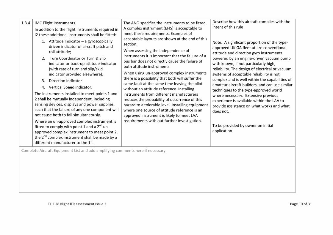
1.3.4 IMC Flight Instruments In addition to the flight instruments required in I2 these additional instruments shall be fitted:
1. Attitude Indicator – a gyroscopically driven indicator of aircraft pitch and roll attitude;
2. Turn Coordinator or Turn & Slip indicator or back-up attitude indicator (with rate of turn and slip/skid indicator provided elsewhere);
3. Direction Indicator 4. Vertical Speed indicator.
The instruments installed to meet points 1 and 2 shall be mutually independent, including sensing devices, displays and power supplies, such that the failure of any one component will not cause both to fail simultaneously. Where an un-approved complex instrument is fitted to comply with point 1 and a 2nd un-approved complex instrument to meet point 2, the 2nd complex instrument shall be made by a different manufacturer to the 1st.
The ANO specifies the instruments to be fitted. A complex instrument (EFIS) is acceptable to meet these requirements. Examples of acceptable layouts are shown at the end of this section. When assessing the independence of instruments it is important that the failure of a bus bar does not directly cause the failure of both attitude instruments. When using un-approved complex instruments there is a possibility that both will suffer the same fault at the same time leaving the pilot without an attitude reference. Installing instruments from different manufacturers reduces the probability of occurrence of this hazard to a tolerable level. Installing equipment where one source of attitude reference is an approved instrument is likely to meet LAA requirements with out further investigation.
Describe how this aircraft complies with the intent of this rule
Note. A significant proportion of the type-approved UK GA fleet utilize conventional attitude and direction gyro instruments powered by an engine-driven vacuum pump with known, if not particularly high, reliability. The design of electrical or vacuum systems of acceptable reliability is not complex and is well within the capabilities of amateur aircraft builders, and can use similar techniques to the type-approved world where necessary. Extensive previous experience is available within the LAA to provide assistance on what works and what does not.
To be provided by owner on initial application
Complete Aircraft Equipment List and add amplifying comments here if necessary
TL 2.28 Night IFR assessment Issue 2 Page 11 of 31
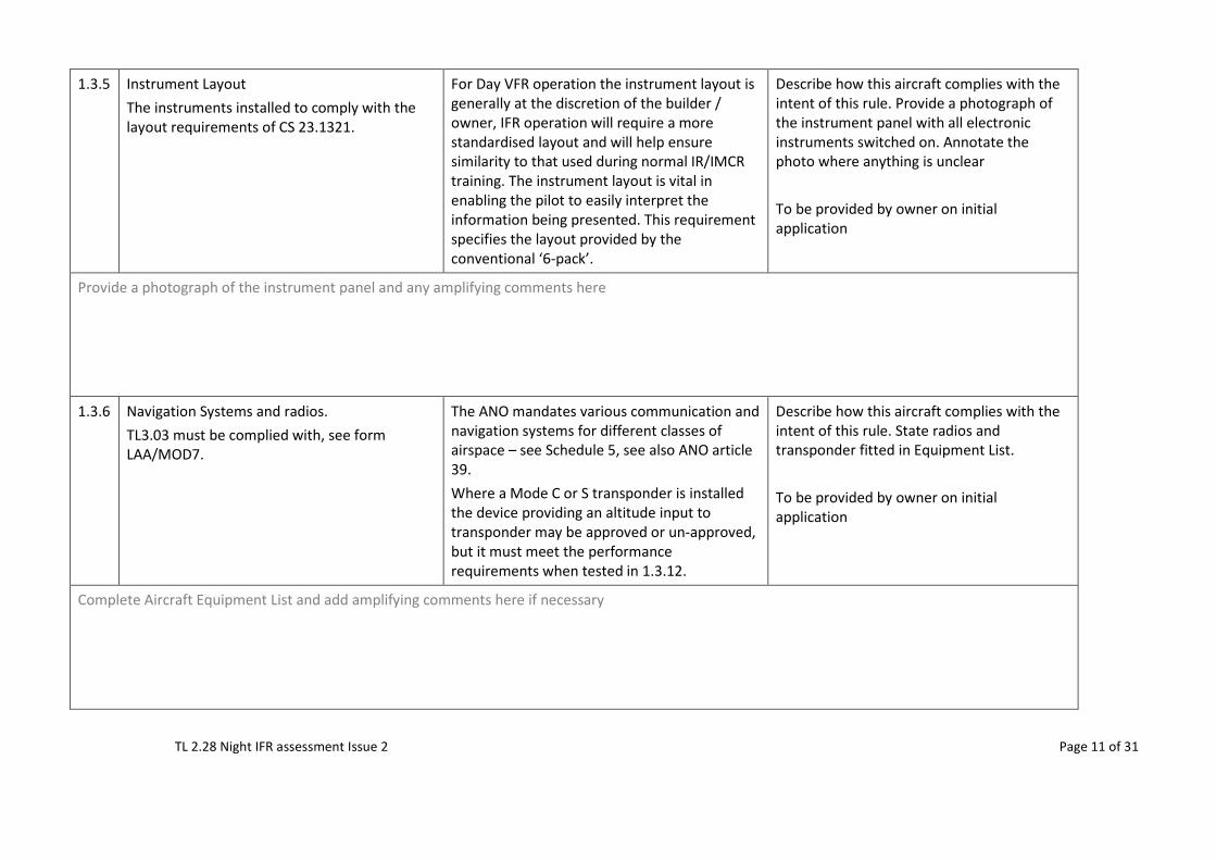
1.3.5 Instrument Layout The instruments installed to comply with the layout requirements of CS 23.1321.
For Day VFR operation the instrument layout is generally at the discretion of the builder / owner, IFR operation will require a more standardised layout and will help ensure similarity to that used during normal IR/IMCR training. The instrument layout is vital in enabling the pilot to easily interpret the information being presented. This requirement specifies the layout provided by the conventional ‘6-pack’.
Describe how this aircraft complies with the intent of this rule. Provide a photograph of the instrument panel with all electronic instruments switched on. Annotate the photo where anything is unclear To be provided by owner on initial application
Provide a photograph of the instrument panel and any amplifying comments here
1.3.6 Navigation Systems and radios. TL3.03 must be complied with, see form LAA/MOD7.
The ANO mandates various communication and navigation systems for different classes of airspace – see Schedule 5, see also ANO article 39. Where a Mode C or S transponder is installed the device providing an altitude input to transponder may be approved or un-approved, but it must meet the performance requirements when tested in 1.3.12.
Describe how this aircraft complies with the intent of this rule. State radios and transponder fitted in Equipment List. To be provided by owner on initial application
Complete Aircraft Equipment List and add amplifying comments here if necessary
TL 2.28 Night IFR assessment Issue 2 Page 12 of 31
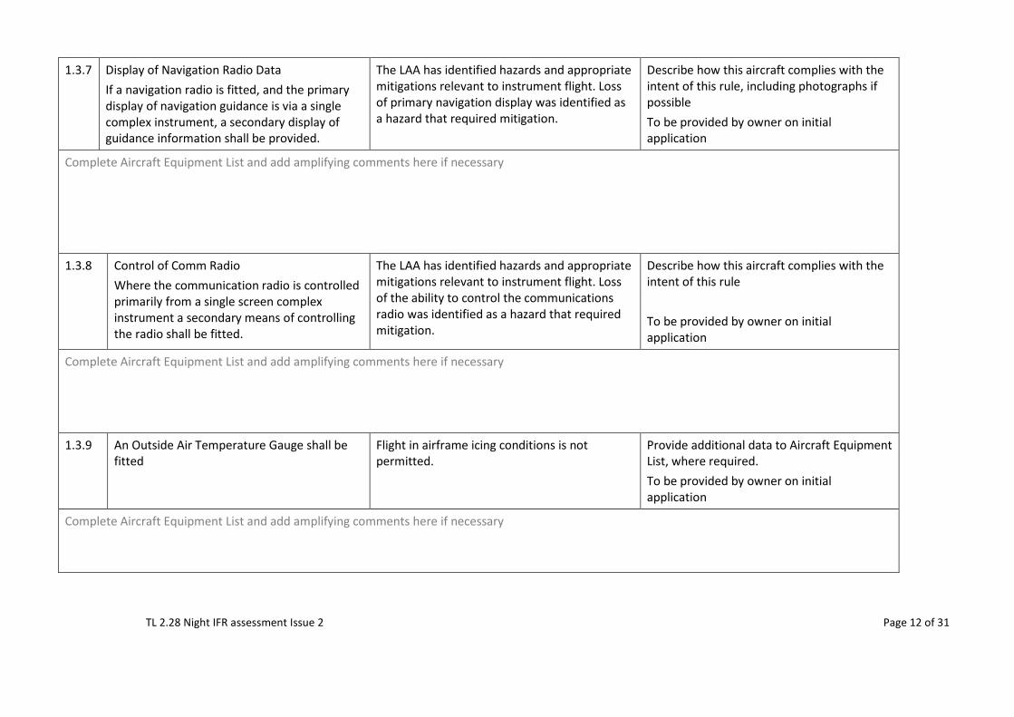
1.3.7 Display of Navigation Radio Data If a navigation radio is fitted, and the primary display of navigation guidance is via a single complex instrument, a secondary display of guidance information shall be provided.
The LAA has identified hazards and appropriate mitigations relevant to instrument flight. Loss of primary navigation display was identified as a hazard that required mitigation.
Describe how this aircraft complies with the intent of this rule, including photographs if possible To be provided by owner on initial application
Complete Aircraft Equipment List and add amplifying comments here if necessary
1.3.8 Control of Comm Radio Where the communication radio is controlled primarily from a single screen complex instrument a secondary means of controlling the radio shall be fitted.
The LAA has identified hazards and appropriate mitigations relevant to instrument flight. Loss of the ability to control the communications radio was identified as a hazard that required mitigation.
Describe how this aircraft complies with the intent of this rule To be provided by owner on initial application
Complete Aircraft Equipment List and add amplifying comments here if necessary
1.3.9 An Outside Air Temperature Gauge shall be fitted
Flight in airframe icing conditions is not permitted.
Provide additional data to Aircraft Equipment List, where required. To be provided by owner on initial application
Complete Aircraft Equipment List and add amplifying comments here if necessary
TL 2.28 Night IFR assessment Issue 2 Page 13 of 31
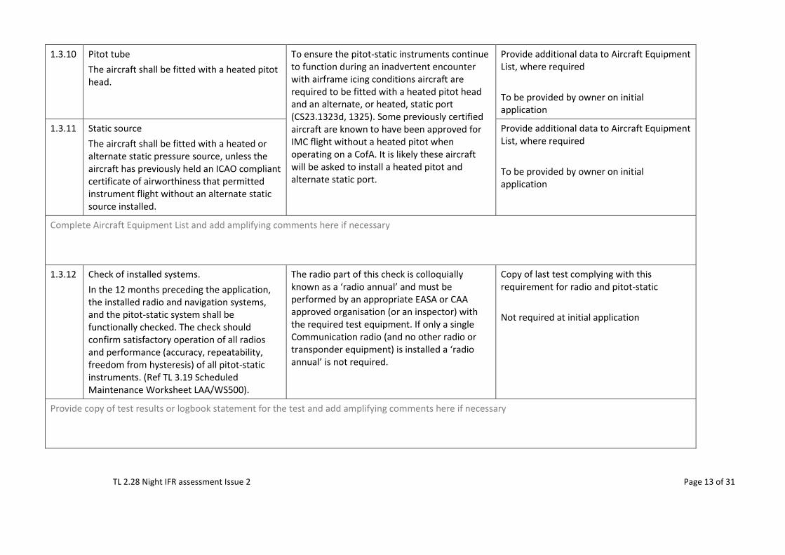
1.3.10 Pitot tube The aircraft shall be fitted with a heated pitot head.
To ensure the pitot-static instruments continue to function during an inadvertent encounter with airframe icing conditions aircraft are required to be fitted with a heated pitot head and an alternate, or heated, static port (CS23.1323d, 1325). Some previously certified aircraft are known to have been approved for IMC flight without a heated pitot when operating on a CofA. It is likely these aircraft will be asked to install a heated pitot and alternate static port.
Provide additional data to Aircraft Equipment List, where required To be provided by owner on initial application
1.3.11 Static source The aircraft shall be fitted with a heated or alternate static pressure source, unless the aircraft has previously held an ICAO compliant certificate of airworthiness that permitted instrument flight without an alternate static source installed.
Provide additional data to Aircraft Equipment List, where required To be provided by owner on initial application
Complete Aircraft Equipment List and add amplifying comments here if necessary
1.3.12 Check of installed systems. In the 12 months preceding the application, the installed radio and navigation systems, and the pitot-static system shall be functionally checked. The check should confirm satisfactory operation of all radios and performance (accuracy, repeatability, freedom from hysteresis) of all pitot-static instruments. (Ref TL 3.19 Scheduled Maintenance Worksheet LAA/WS500).
The radio part of this check is colloquially known as a ‘radio annual’ and must be performed by an appropriate EASA or CAA approved organisation (or an inspector) with the required test equipment. If only a single Communication radio (and no other radio or transponder equipment) is installed a ‘radio annual’ is not required.
Copy of last test complying with this requirement for radio and pitot-static Not required at initial application
Provide copy of test results or logbook statement for the test and add amplifying comments here if necessary
TL 2.28 Night IFR assessment Issue 2 Page 14 of 31
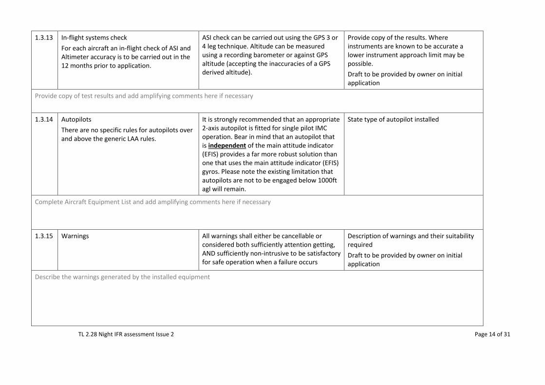
1.3.13 In-flight systems check For each aircraft an in-flight check of ASI and Altimeter accuracy is to be carried out in the 12 months prior to application.
ASI check can be carried out using the GPS 3 or 4 leg technique. Altitude can be measured using a recording barometer or against GPS altitude (accepting the inaccuracies of a GPS derived altitude).
Provide copy of the results. Where instruments are known to be accurate a lower instrument approach limit may be possible. Draft to be provided by owner on initial application
Provide copy of test results and add amplifying comments here if necessary
1.3.14 Autopilots There are no specific rules for autopilots over and above the generic LAA rules.
It is strongly recommended that an appropriate 2-axis autopilot is fitted for single pilot IMC operation. Bear in mind that an autopilot that is independent of the main attitude indicator (EFIS) provides a far more robust solution than one that uses the main attitude indicator (EFIS) gyros. Please note the existing limitation that autopilots are not to be engaged below 1000ft agl will remain.
State type of autopilot installed
Complete Aircraft Equipment List and add amplifying comments here if necessary
1.3.15 Warnings All warnings shall either be cancellable or considered both sufficiently attention getting, AND sufficiently non-intrusive to be satisfactory for safe operation when a failure occurs
Description of warnings and their suitability required Draft to be provided by owner on initial application
Describe the warnings generated by the installed equipment
TL 2.28 Night IFR assessment Issue 2 Page 15 of 31
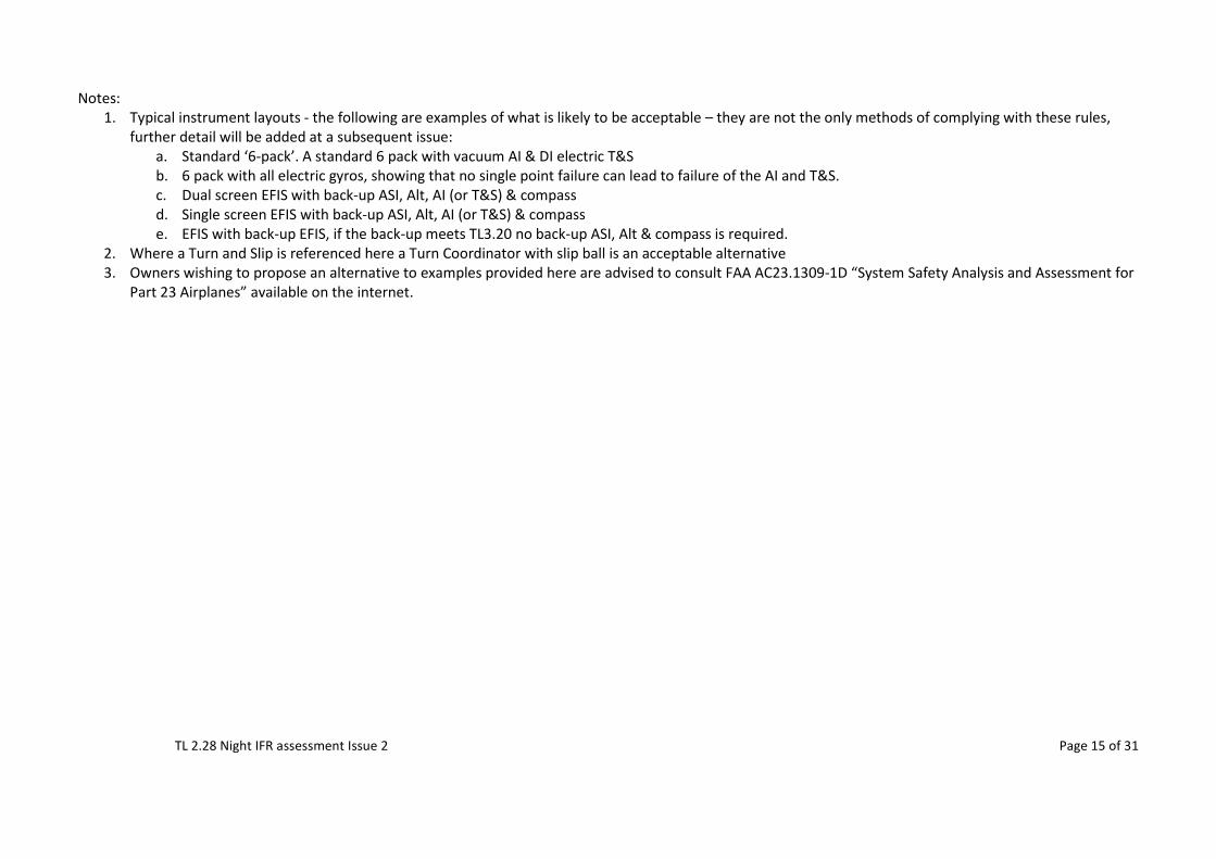
Notes:
1. Typical instrument layouts - the following are examples of what is likely to be acceptable – they are not the only methods of complying with these rules, further detail will be added at a subsequent issue:
a. Standard ‘6-pack’. A standard 6 pack with vacuum AI & DI electric T&S b. 6 pack with all electric gyros, showing that no single point failure can lead to failure of the AI and T&S. c. Dual screen EFIS with back-up ASI, Alt, AI (or T&S) & compass d. Single screen EFIS with back-up ASI, Alt, AI (or T&S) & compass e. EFIS with back-up EFIS, if the back-up meets TL3.20 no back-up ASI, Alt & compass is required.
2. Where a Turn and Slip is referenced here a Turn Coordinator with slip ball is an acceptable alternative 3. Owners wishing to propose an alternative to examples provided here are advised to consult FAA AC23.1309-1D “System Safety Analysis and Assessment for
Part 23 Airplanes” available on the internet.
TL 2.28 Night IFR assessment Issue 2 Page 16 of 31
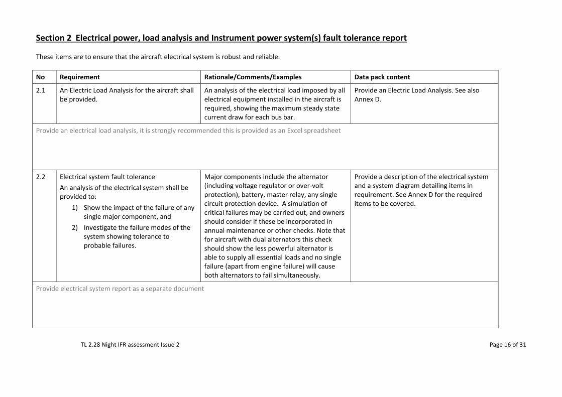
Section 2 Electrical power, load analysis and Instrument power system(s) fault tolerance report These items are to ensure that the aircraft electrical system is robust and reliable. No Requirement Rationale/Comments/Examples Data pack content
2.1 An Electric Load Analysis for the aircraft shall be provided.
An analysis of the electrical load imposed by all electrical equipment installed in the aircraft is required, showing the maximum steady state current draw for each bus bar.
Provide an Electric Load Analysis. See also Annex D.
Provide an electrical load analysis, it is strongly recommended this is provided as an Excel spreadsheet
2.2 Electrical system fault tolerance An analysis of the electrical system shall be provided to:
1) Show the impact of the failure of any single major component, and
2) Investigate the failure modes of the system showing tolerance to probable failures.
Major components include the alternator (including voltage regulator or over-volt protection), battery, master relay, any single circuit protection device. A simulation of critical failures may be carried out, and owners should consider if these be incorporated in annual maintenance or other checks. Note that for aircraft with dual alternators this check should show the less powerful alternator is able to supply all essential loads and no single failure (apart from engine failure) will cause both alternators to fail simultaneously.
Provide a description of the electrical system and a system diagram detailing items in requirement. See Annex D for the required items to be covered.
Provide electrical system report as a separate document
TL 2.28 Night IFR assessment Issue 2 Page 17 of 31
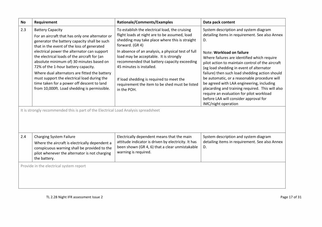
No Requirement Rationale/Comments/Examples Data pack content
2.3 Battery Capacity For an aircraft that has only one alternator or generator the battery capacity shall be such that in the event of the loss of generated electrical power the alternator can support the electrical loads of the aircraft for (an absolute minimum of) 30 minutes based on 72% of the 1-hour battery capacity. Where dual alternators are fitted the battery must support the electrical load during the time taken for a power off descent to land from 10,000ft. Load shedding is permissible.
To establish the electrical load, the cruising flight loads at night are to be assumed, load shedding may take place where this is straight forward. (GR 4) In absence of an analysis, a physical test of full load may be acceptable. It is strongly recommended that battery capacity exceeding 45 minutes is installed. If load shedding is required to meet the requirement the item to be shed must be listed in the POH.
System description and system diagram detailing items in requirement. See also Annex D. Note: Workload on failure Where failures are identified which require pilot action to maintain control of the aircraft (eg load shedding in event of alternator failure) then such load shedding action should be automatic, or a reasonable procedure will be agreed with LAA engineering, including placarding and training required. This will also require an evaluation for pilot workload before LAA will consider approval for IMC/night operation
It is strongly recommended this is part of the Electrical Load Analysis spreadsheet
2.4 Charging System Failure Where the aircraft is electrically dependent a conspicuous warning shall be provided to the pilot whenever the alternator is not charging the battery.
Electrically dependent means that the main attitude indicator is driven by electricity. It has been shown (GR 4, 6) that a clear unmistakable warning is required.
System description and system diagram detailing items in requirement. See also Annex D.
Provide in the electrical system report
TL 2.28 Night IFR assessment Issue 2 Page 18 of 31
No Requirement Rationale/Comments/Examples Data pack content
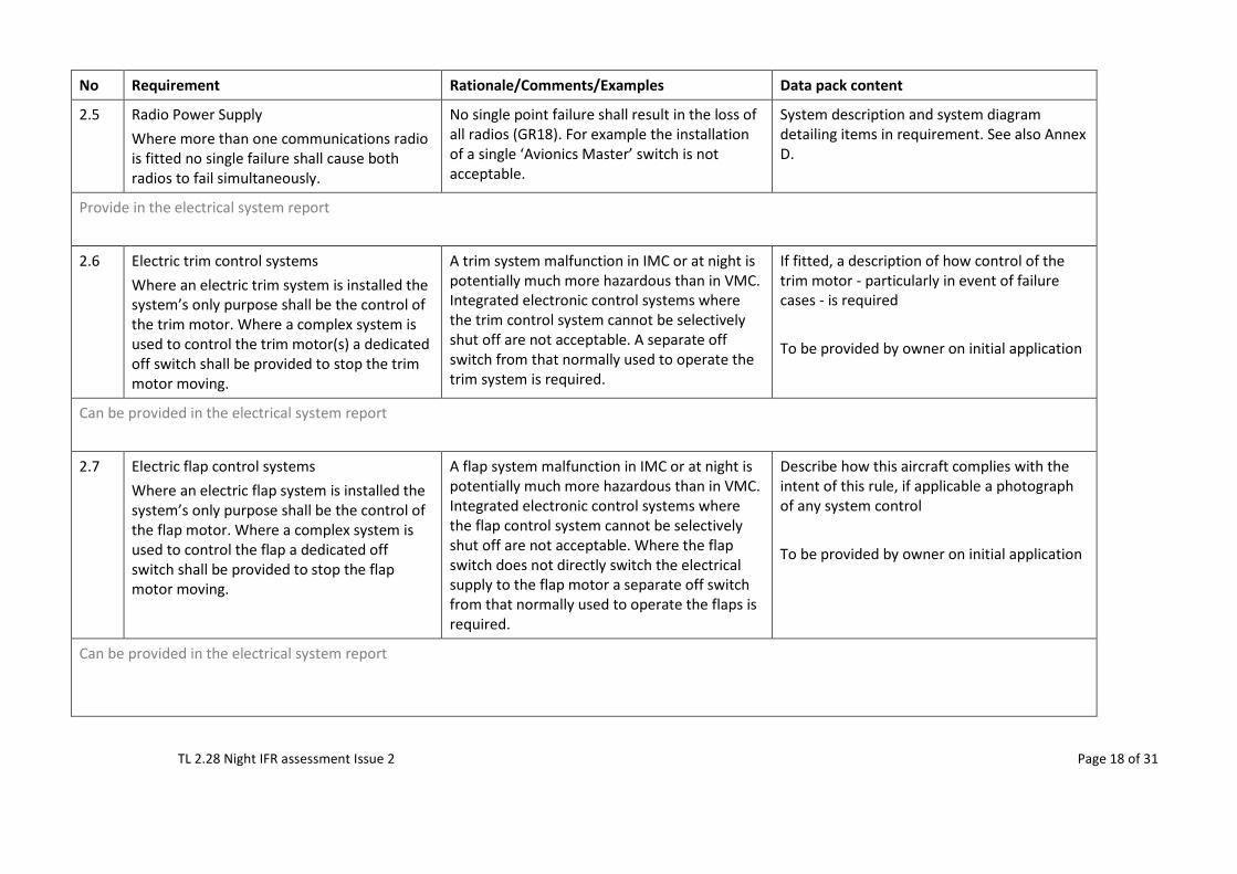
2.5 Radio Power Supply Where more than one communications radio is fitted no single failure shall cause both radios to fail simultaneously.
No single point failure shall result in the loss of all radios (GR18). For example the installation of a single ‘Avionics Master’ switch is not acceptable.
System description and system diagram detailing items in requirement. See also Annex D.
Provide in the electrical system report
2.6 Electric trim control systems Where an electric trim system is installed the system’s only purpose shall be the control of the trim motor. Where a complex system is used to control the trim motor(s) a dedicated off switch shall be provided to stop the trim motor moving.
A trim system malfunction in IMC or at night is potentially much more hazardous than in VMC. Integrated electronic control systems where the trim control system cannot be selectively shut off are not acceptable. A separate off switch from that normally used to operate the trim system is required.
If fitted, a description of how control of the trim motor - particularly in event of failure cases - is required To be provided by owner on initial application
Can be provided in the electrical system report
2.7 Electric flap control systems Where an electric flap system is installed the system’s only purpose shall be the control of the flap motor. Where a complex system is used to control the flap a dedicated off switch shall be provided to stop the flap motor moving.
A flap system malfunction in IMC or at night is potentially much more hazardous than in VMC. Integrated electronic control systems where the flap control system cannot be selectively shut off are not acceptable. Where the flap switch does not directly switch the electrical supply to the flap motor a separate off switch from that normally used to operate the flaps is required.
Describe how this aircraft complies with the intent of this rule, if applicable a photograph of any system control To be provided by owner on initial application
Can be provided in the electrical system report
TL 2.28 Night IFR assessment Issue 2 Page 19 of 31
No Requirement Rationale/Comments/Examples Data pack content
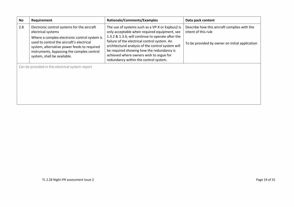
2.8 Electronic control systems for the aircraft electrical systems Where a complex electronic control system is used to control the aircraft’s electrical system, alternative power feeds to required instruments, bypassing the complex control system, shall be available.
The use of systems such as a VP-X or Expbus2 is only acceptable when required equipment, see 1.3.2 & 1.3.4, will continue to operate after the failure of the electrical control system. An architectural analysis of the control system will be required showing how the redundancy is achieved where owners wish to argue for redundancy within the control system.
Describe how this aircraft complies with the intent of this rule To be provided by owner on initial application
Can be provided in the electrical system report
TL 2.28 Night IFR assessment Issue 2 Page 20 of 31
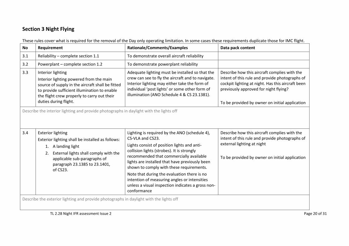
Section 3 Night Flying These rules cover what is required for the removal of the Day only operating limitation. In some cases these requirements duplicate those for IMC flight. No Requirement Rationale/Comments/Examples Data pack content
3.1 Reliability – complete section 1.1 To demonstrate overall aircraft reliability
3.2 Powerplant – complete section 1.2 To demonstrate powerplant reliability
3.3 Interior lighting Interior lighting powered from the main source of supply in the aircraft shall be fitted to provide sufficient illumination to enable the flight crew properly to carry out their duties during flight.
Adequate lighting must be installed so that the crew can see to fly the aircraft and to navigate. Interior lighting may either take the form of individual ‘post lights’ or some other form of illumination (ANO Schedule 4 & CS 23.1381).
Describe how this aircraft complies with the intent of this rule and provide photographs of cockpit lighting at night. Has this aircraft been previously approved for night flying? To be provided by owner on initial application
Describe the interior lighting and provide photographs in daylight with the lights off
3.4 Exterior lighting Exterior lighting shall be installed as follows:
1. A landing light 2. External lights shall comply with the
applicable sub-paragraphs of paragraph 23.1385 to 23.1401, of CS23.
Lighting is required by the ANO (schedule 4), CS-VLA and CS23. Lights consist of position lights and anti-collision lights (strobes). It is strongly recommended that commercially available lights are installed that have previously been shown to comply with these requirements. Note that during the evaluation there is no intention of measuring angles or intensities unless a visual inspection indicates a gross non-conformance
Describe how this aircraft complies with the intent of this rule and provide photographs of external lighting at night To be provided by owner on initial application
Describe the exterior lighting and provide photographs in daylight with the lights off
TL 2.28 Night IFR assessment Issue 2 Page 21 of 31
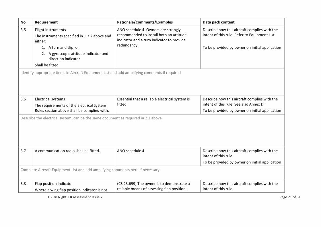
No Requirement Rationale/Comments/Examples Data pack content
3.5 Flight Instruments The instruments specified in 1.3.2 above and either:
1. A turn and slip, or 2. A gyroscopic attitude indicator and
direction indicator Shall be fitted.
ANO schedule 4. Owners are strongly recommended to install both an attitude indicator and a turn indicator to provide redundancy.
Describe how this aircraft complies with the intent of this rule. Refer to Equipment List. To be provided by owner on initial application
Identify appropriate items in Aircraft Equipment List and add amplifying comments if required
3.6 Electrical systems The requirements of the Electrical System Rules section above shall be complied with.
Essential that a reliable electrical system is fitted.
Describe how this aircraft complies with the intent of this rule. See also Annex D. To be provided by owner on initial application
Describe the electrical system, can be the same document as required in 2.2 above
3.7 A communication radio shall be fitted. ANO schedule 4 Describe how this aircraft complies with the intent of this rule To be provided by owner on initial application
Complete Aircraft Equipment List and add amplifying comments here if necessary
3.8 Flap position indicator Where a wing flap position indicator is not
(CS 23.699) The owner is to demonstrate a reliable means of assessing flap position.
Describe how this aircraft complies with the intent of this rule
TL 2.28 Night IFR assessment Issue 2 Page 22 of 31
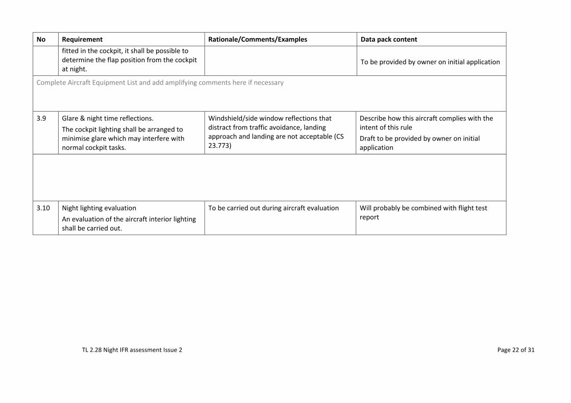
No Requirement Rationale/Comments/Examples Data pack content fitted in the cockpit, it shall be possible to determine the flap position from the cockpit at night.
To be provided by owner on initial application
Complete Aircraft Equipment List and add amplifying comments here if necessary
3.9 Glare & night time reflections. The cockpit lighting shall be arranged to minimise glare which may interfere with normal cockpit tasks.
Windshield/side window reflections that distract from traffic avoidance, landing approach and landing are not acceptable (CS 23.773)
Describe how this aircraft complies with the intent of this rule Draft to be provided by owner on initial application
3.10 Night lighting evaluation An evaluation of the aircraft interior lighting shall be carried out.
To be carried out during aircraft evaluation Will probably be combined with flight test report
TL 2.28 Night IFR assessment Issue 2 Page 23 of 31
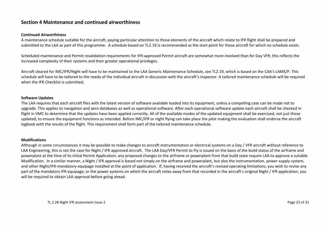
Section 4 Maintenance and continued airworthiness Continued Airworthiness A maintenance schedule suitable for the aircraft, paying particular attention to those elements of the aircraft which relate to IFR flight shall be prepared and submitted to the LAA as part of this programme. A schedule based on TL2.19 is recommended as the start point for those aircraft for which no schedule exists. Scheduled maintenance and Permit revalidation requirements for IFR-approved Permit aircraft are somewhat more involved than for Day VFR; this reflects the increased complexity of their systems and their greater operational privileges. Aircraft cleared for IMC/IFR/Night will have to be maintained to the LAA Generic Maintenance Schedule, see TL2.19, which is based on the CAA’s LAMS/P. This schedule will have to be tailored to the needs of the individual aircraft in discussion with the aircraft’s inspector. A tailored maintenance schedule will be required when the IFR Checklist is submitted. Software Updates The LAA requires that each aircraft flies with the latest version of software available loaded into its equipment, unless a compelling case can be made not to upgrade. This applies to navigation and aero databases as well as operational software. After each operational software update each aircraft shall be checked in flight in VMC to determine that the updates have been applied correctly. All of the available modes of the updated equipment shall be exercised, not just those updated, to ensure the equipment functions as intended. Before IMC/IFR or night flying can take place the pilot making the evaluation shall endorse the aircraft logbook with the results of the flight. This requirement shall form part of the tailored maintenance schedule. Modifications Although in some circumstances it may be possible to make changes to aircraft instrumentation or electrical systems on a Day / VFR aircraft without reference to LAA Engineering, this is not the case for Night / IFR-approved aircraft. The LAA Day/VFR Permit to Fly is issued on the basis of the build status of the airframe and powerplant at the time of its initial Permit Application; any proposed changes to the airframe or powerplant from that build state require LAA to approve a suitable Modification. In a similar manner, a Night / IFR approval is based not simply on the airframe and powerplant, but also the instrumentation, power supply system, and other Night/IFR-mandatory equipage installed at the point of application. If, having received the aircraft’s revised operating limitations, you wish to revise any part of the mandatory IFR equipage, or the power systems on which the aircraft relies away from that recorded in the aircraft’s original Night / IFR application, you will be required to obtain LAA approval before going ahead.
TL 2.28 Night IFR assessment Issue 2 Page 24 of 31
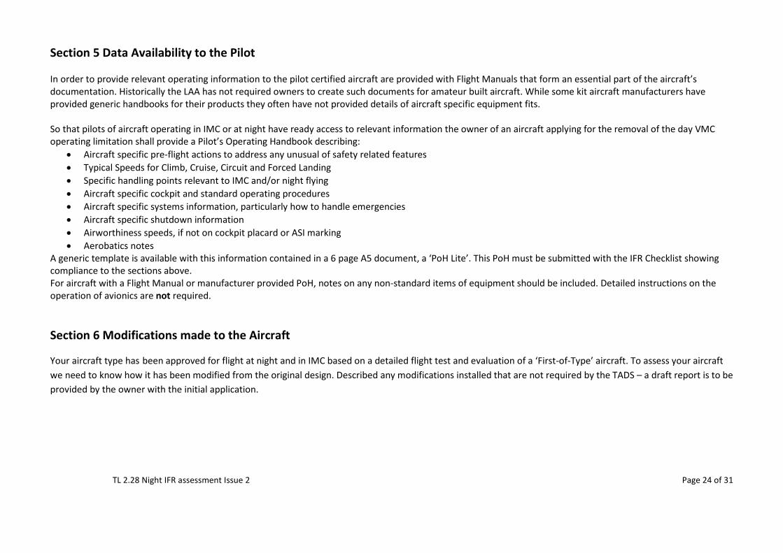
Section 5 Data Availability to the Pilot In order to provide relevant operating information to the pilot certified aircraft are provided with Flight Manuals that form an essential part of the aircraft’s documentation. Historically the LAA has not required owners to create such documents for amateur built aircraft. While some kit aircraft manufacturers have provided generic handbooks for their products they often have not provided details of aircraft specific equipment fits. So that pilots of aircraft operating in IMC or at night have ready access to relevant information the owner of an aircraft applying for the removal of the day VMC operating limitation shall provide a Pilot’s Operating Handbook describing:
• Aircraft specific pre-flight actions to address any unusual of safety related features • Typical Speeds for Climb, Cruise, Circuit and Forced Landing • Specific handling points relevant to IMC and/or night flying • Aircraft specific cockpit and standard operating procedures • Aircraft specific systems information, particularly how to handle emergencies • Aircraft specific shutdown information • Airworthiness speeds, if not on cockpit placard or ASI marking • Aerobatics notes
A generic template is available with this information contained in a 6 page A5 document, a ‘PoH Lite’. This PoH must be submitted with the IFR Checklist showing compliance to the sections above. For aircraft with a Flight Manual or manufacturer provided PoH, notes on any non-standard items of equipment should be included. Detailed instructions on the operation of avionics are not required. Section 6 Modifications made to the Aircraft
Your aircraft type has been approved for flight at night and in IMC based on a detailed flight test and evaluation of a ‘First-of-Type’ aircraft. To assess your aircraft we need to know how it has been modified from the original design. Described any modifications installed that are not required by the TADS – a draft report is to be provided by the owner with the initial application.
TL 2.28 Night IFR assessment Issue 2 Page 25 of 31
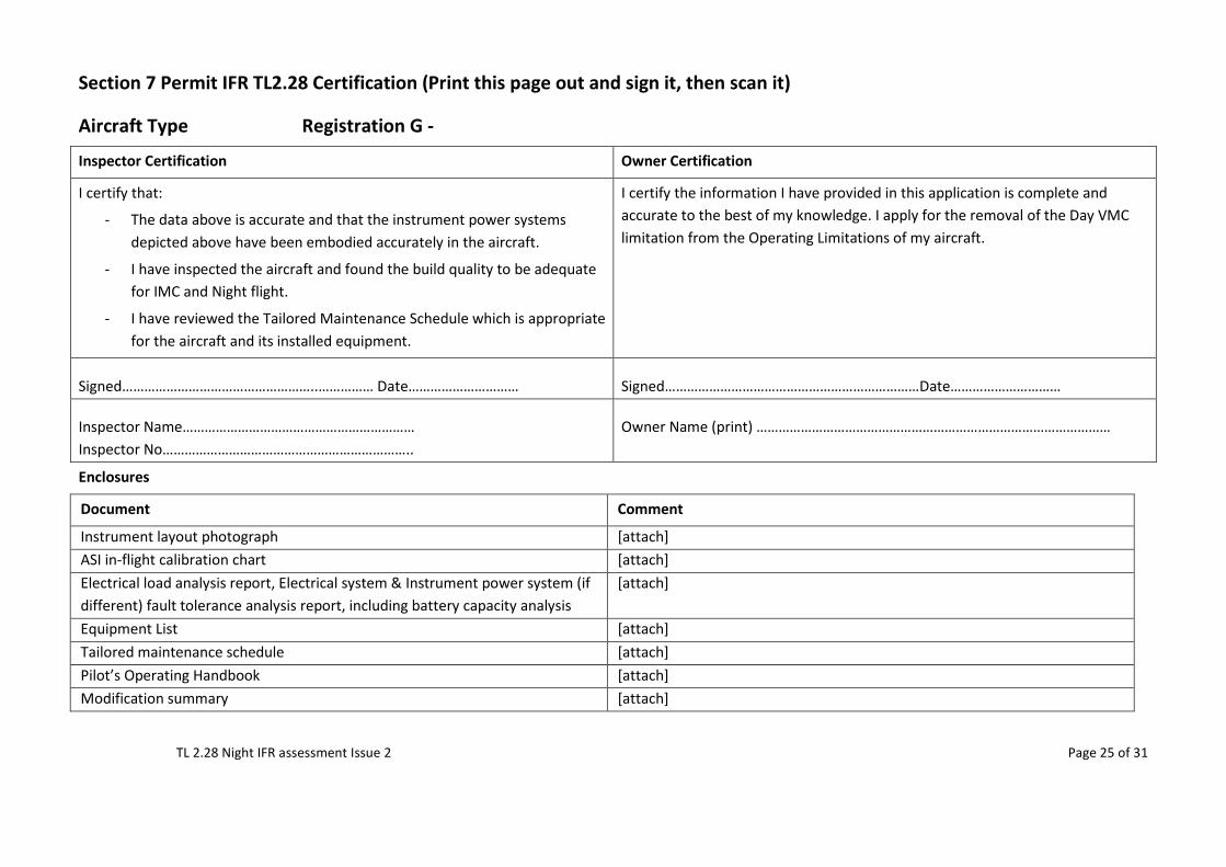
Section 7 Permit IFR TL2.28 Certification (Print this page out and sign it, then scan it)
Aircraft Type Registration G -
Inspector Certification Owner Certification
I certify that:
- The data above is accurate and that the instrument power systems depicted above have been embodied accurately in the aircraft.
- I have inspected the aircraft and found the build quality to be adequate for IMC and Night flight.
- I have reviewed the Tailored Maintenance Schedule which is appropriate for the aircraft and its installed equipment.
I certify the information I have provided in this application is complete and accurate to the best of my knowledge. I apply for the removal of the Day VMC limitation from the Operating Limitations of my aircraft.
Signed……………………………………………..…………… Date………………………… Signed……………………………………………………………Date…………………………
Inspector Name……………………………………………………… Inspector No…………………………………………………………..
Owner Name (print) ……………………………………………………………………………………
Enclosures
Document Comment
Instrument layout photograph [attach] ASI in-flight calibration chart [attach] Electrical load analysis report, Electrical system & Instrument power system (if different) fault tolerance analysis report, including battery capacity analysis
[attach]
Equipment List [attach] Tailored maintenance schedule [attach] Pilot’s Operating Handbook [attach] Modification summary [attach]
TL 2.28 Night IFR assessment Issue 2
Page 26 of 31
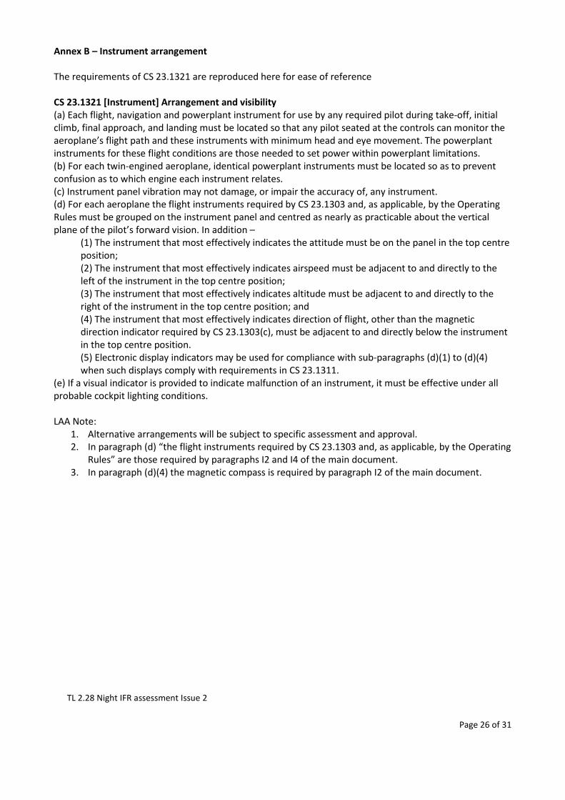
Annex B – Instrument arrangement The requirements of CS 23.1321 are reproduced here for ease of reference CS 23.1321 [Instrument] Arrangement and visibility (a) Each flight, navigation and powerplant instrument for use by any required pilot during take-off, initial climb, final approach, and landing must be located so that any pilot seated at the controls can monitor the aeroplane’s flight path and these instruments with minimum head and eye movement. The powerplant instruments for these flight conditions are those needed to set power within powerplant limitations. (b) For each twin-engined aeroplane, identical powerplant instruments must be located so as to prevent confusion as to which engine each instrument relates. (c) Instrument panel vibration may not damage, or impair the accuracy of, any instrument. (d) For each aeroplane the flight instruments required by CS 23.1303 and, as applicable, by the Operating Rules must be grouped on the instrument panel and centred as nearly as practicable about the vertical plane of the pilot’s forward vision. In addition –
(1) The instrument that most effectively indicates the attitude must be on the panel in the top centre position; (2) The instrument that most effectively indicates airspeed must be adjacent to and directly to the left of the instrument in the top centre position; (3) The instrument that most effectively indicates altitude must be adjacent to and directly to the right of the instrument in the top centre position; and (4) The instrument that most effectively indicates direction of flight, other than the magnetic direction indicator required by CS 23.1303(c), must be adjacent to and directly below the instrument in the top centre position. (5) Electronic display indicators may be used for compliance with sub-paragraphs (d)(1) to (d)(4) when such displays comply with requirements in CS 23.1311.
(e) If a visual indicator is provided to indicate malfunction of an instrument, it must be effective under all probable cockpit lighting conditions. LAA Note:
1. Alternative arrangements will be subject to specific assessment and approval. 2. In paragraph (d) “the flight instruments required by CS 23.1303 and, as applicable, by the Operating
Rules” are those required by paragraphs I2 and I4 of the main document. 3. In paragraph (d)(4) the magnetic compass is required by paragraph I2 of the main document.
TL 2.28 Night IFR assessment Issue 2
Page 27 of 31
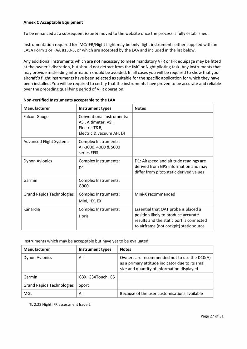
Annex C Acceptable Equipment To be enhanced at a subsequent issue & moved to the website once the process is fully established. Instrumentation required for IMC/IFR/Night flight may be only flight instruments either supplied with an EASA Form 1 or FAA 8130-3, or which are accepted by the LAA and included in the list below. Any additional instruments which are not necessary to meet mandatory VFR or IFR equipage may be fitted at the owner’s discretion, but should not detract from the IMC or Night piloting task. Any instruments that may provide misleading information should be avoided. In all cases you will be required to show that your aircraft’s flight instruments have been selected as suitable for the specific application for which they have been installed. You will be required to certify that the instruments have proven to be accurate and reliable over the preceding qualifying period of VFR operation.
Non-certified Instruments acceptable to the LAA
Manufacturer Instrument types Notes
Falcon Gauge Conventional Instruments: ASI, Altimeter, VSI, Electric T&B, Electric & vacuum AH, DI
Advanced Flight Systems Complex Instruments: AF-3000, 4000 & 5000 series EFIS
Dynon Avionics Complex Instruments: D1
D1: Airspeed and altitude readings are derived from GPS information and may differ from pitot-static derived values
Garmin Complex Instruments: G900
Grand Rapids Technologies Complex Instruments: Mini, HX, EX
Mini-X recommended
Kanardia Complex Instruments: Horis
Essential that OAT probe is placed a position likely to produce accurate results and the static port is connected to airframe (not cockpit) static source
Instruments which may be acceptable but have yet to be evaluated:
Manufacturer Instrument types Notes
Dynon Avionics All Owners are recommended not to use the D10(A) as a primary attitude indicator due to its small size and quantity of information displayed
Garmin G3X, G3XTouch, G5
Grand Rapids Technologies Sport
MGL All Because of the user customisations available
TL 2.28 Night IFR assessment Issue 2
Page 28 of 31
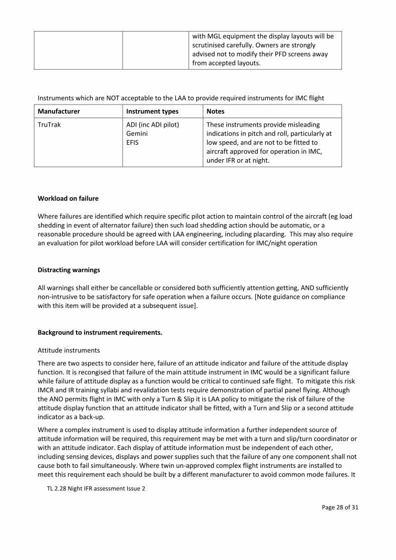
with MGL equipment the display layouts will be scrutinised carefully. Owners are strongly advised not to modify their PFD screens away from accepted layouts.
Instruments which are NOT acceptable to the LAA to provide required instruments for IMC flight
Manufacturer Instrument types Notes
TruTrak ADI (inc ADI pilot) Gemini EFIS
These instruments provide misleading indications in pitch and roll, particularly at low speed, and are not to be fitted to aircraft approved for operation in IMC, under IFR or at night.
Workload on failure Where failures are identified which require specific pilot action to maintain control of the aircraft (eg load shedding in event of alternator failure) then such load shedding action should be automatic, or a reasonable procedure should be agreed with LAA engineering, including placarding. This may also require an evaluation for pilot workload before LAA will consider certification for IMC/night operation Distracting warnings All warnings shall either be cancellable or considered both sufficiently attention getting, AND sufficiently non-intrusive to be satisfactory for safe operation when a failure occurs. [Note guidance on compliance with this item will be provided at a subsequent issue]. Background to instrument requirements. Attitude instruments
There are two aspects to consider here, failure of an attitude indicator and failure of the attitude display function. It is recongised that failure of the main attitude instrument in IMC would be a significant failure while failure of attitude display as a function would be critical to continued safe flight. To mitigate this risk IMCR and IR training syllabi and revalidation tests require demonstration of partial panel flying. Although the ANO permits flight in IMC with only a Turn & Slip it is LAA policy to mitigate the risk of failure of the attitude display function that an attitude indicator shall be fitted, with a Turn and Slip or a second attitude indicator as a back-up.
Where a complex instrument is used to display attitude information a further independent source of attitude information will be required, this requirement may be met with a turn and slip/turn coordinator or with an attitude indicator. Each display of attitude information must be independent of each other, including sensing devices, displays and power supplies such that the failure of any one component shall not cause both to fail simultaneously. Where twin un-approved complex flight instruments are installed to meet this requirement each should be built by a different manufacturer to avoid common mode failures. It
TL 2.28 Night IFR assessment Issue 2
Page 29 of 31
is important that these instruments use independent power supplies to prevent one failure taking down both instruments.
Direction Indicators
Mechanical gyroscopic direction indicators are, by definition, subject to precession and must be regularly synchronized to the aircraft’s magnetic compass; this regular re-synchronization task provides an ideal opportunity for the pilot to continually assess its accuracy. Failure of the DI would increase the pilot’s workload but would not impose a serious risk. Where the DI function is provided by an EFIS, magnetic heading information is invariably supplied by a magnetometer mounted remotely from the EFIS screen in a magnetically quiet part of the airframe. A stable heading indication is provided using the EFIS AHRS (attitude & heading reference system) for short term stability and the magnetometer for longer term accuracy, and is potentially a superior solution to that of a conventional mechanical DI. Instrument Power Systems
A significant proportion of the type-approved UK GA fleet utilise conventional attitude and direction gyro instruments powered by an engine-driven vacuum pump with known, if not particularly high, reliability. The design of electrical or vacuum systems of acceptable reliability is not complex and is well within the capabilities of amateur aircraft builders, and can use similar techniques to the type-approved world where necessary. Extensive previous experience is available within the LAA to provide assistance on what works and what does not.
Power systems designed using these generic techniques will be able to meet, or exceed, the baseline level of reliability achieved by the ubiquitous vacuum system. The architecture of these systems is more important in that they must be designed to prevent the failure of any one component from removing all power to the attitude display system. To ensure that adequate back-up instrument power systems are available a flight instrument power system functional hazard assessment is required. This assessment will be required to demonstrate that the failure of any one component (eg alternator, battery, battery contactor, master switch) will not result in the loss of flight critical data. An electrical load analysis will also be required to show that the basic electrical system can support the loads placed upon it, and that for electrical only systems the battery can support essential loads for a period of an absolute minimum of 30 minutes, although it is strongly recommended that the battery can support essential loads for 45 minutes.
TL 2.28 Night IFR assessment Issue 2
Page 30 of 31
Annex D – Electrical redundancy This annex describes the items that must be covered in the electrical systems redundancy report. Applicants are required to determine where the potential failures points are in their aircraft’s systems, how the installed systems might fail, and how the aircraft will survive any of the identified failures. Note each failure need only be considered in isolation. It is not required to survive multiple unrelated failures. If flying in IMC it is expected the pilot will immediate fly into VMC using whatever outside assistance is available to mitigate the impact of a second failure to an essential system. The redundancy report must consider the items below and how each of the failures below is mitigated. Any failures particular to the aircraft concerned should also be addressed. The reaction to some of these failures may seem obvious or straight forward. It is important that the mitigation each is described.
- Provide a brief description of the instrumentation system and its how it is powered (electric, vacuum)
- Provide a description of the electrical system covering battery(s), alternator(s) and busbar(s) installed. The relays used to energise the electrical services/busbars and any other relevant features.
- Describe how the electrical system operates in normal circumstances - Discuss how voltage regulation, under volt warning and over volt protection is achieved - List/describe which services are powered from which busbar. - Describe over current protection is achieved. - How can the owner be sure the main power connections will be reliable? - Provide a diagram showing the main elements of the electrical system, at least those described
above, it is not necessary to show each individual service or circuit breaker/fuse. - List all the elements of the electrical system that draw power and show the alternator can support
all of the continuous loads. Calculate the battery endurance if only a single alternator is fitted – load shedding of non-essential services is permissible. It is strongly recommended a spreadsheet calculating battery endurance is supplied with the report.
- Describe how the following failures will be handled, some may appear obvious, but you are required to consider them and document how your system responds, or the implications of the failure. [Italic text in square brackets provides guidance on scope]:
o Battery failure before engine start [Symptom: Unable to switch on aircraft systems until after engine start, engine cannot be started without external assistance – Outcome: VFR flight only as no electrical back-up if alternator fails]
o Main contactor failure before engine start [Symptom: Unable to switch on aircraft systems until after engine start, engine cannot be started without external assistance – Outcome: VFR flight only as no electrical back-up if alternator fails]
o Battery or main contactor failure after engine start o Alternator failure after engine start [Symptom: low voltage warning – Outcome: return to
VMC as soon as practicable, shed non-essential electrical loads] Requires battery endurance to be calculated.
o Power failure to main AI [Symptom: Main AI malfunctions – Outcome: return to VMC as soon as practicable using stand-by AI]
o Power failure to standby AI/T&S [Symptom: Stand-by AI malfunctions – Outcome: return to VMC as soon as practicable using main AI]
o Short circuit of the bus used to power the instruments [Symptom: Several instruments fail - Outcome: return to VMC as soon as practicable using remaining instruments]
TL 2.28 Night IFR assessment Issue 2
Page 31 of 31
o Failure of main or standby AI [Symptom: Main AI malfunctions (also consider how this failure would manifest itself) – Outcome: return to VMC as soon as practicable using stand-by AI]
o Communication radio redundancy – if more than one com radio installed o Any aircraft/equipment specific failures
- Discuss any areas where the description above does not clearly meet the TL2.28 rules. If using an EFIS this may be an appropriate document to show how the EFIS configuration meets the instrument display rules, with pictures of the relevant displays. Discuss any areas where the pilot can configure or change the EFIS display while flying.