
TL1 Alarms and Errors - Cisco...GCC-EOC MJ/NSA The GCC Embedded Operat ion Channel Failure alarm...
60
CHAPTER 7-1 Cisco ONS 15454 and Cisco ONS 15327 TL1 Command Guide, R4.6 October 2008 7 TL1 Alarms and Errors This chapter provides TL1 alarm and error information supported by the Cisco ONS 15454 and Cisco ONS 15327, including: • Alarms, page 7-1 • Conditions, page 7-18 • Errors, page 7-27 • Echo, page 7-59 Each alarm includes a description and severity. Errors are listed by error type and include error message. Conditions are not alarmed (NA) or not reported (NR) and are listed in the “Conditions” section on page 7-18 Note The terms "Unidirectional Path Switched Ring" and "UPSR" may appear in Cisco literature. These terms do not refer to using Cisco ONS 15xxx products in a unidirectional path switched ring configuration. Rather, these terms, as well as "Path Protected Mesh Network" and "PPMN," refer generally to Cisco's path protection feature, which may be used in any topological network configuration. Cisco does not recommend using its path protection feature in any particular topological network configuration. 7.1 Alarms Refer to “Alarm Troubleshooting” in the Cisco ONS 15454 Troubleshooting Guide or the Cisco ONS 15327 Troubleshooting Guide for complete alarm definitions, trouble notifications, and fault recovery procedures. The alarms are listed alphabetically by alarmable object:
Transcript of TL1 Alarms and Errors - Cisco...GCC-EOC MJ/NSA The GCC Embedded Operat ion Channel Failure alarm...
Cisco ONS 15454 and CisOctober 2008
C H A P T E R7
TL1 Alarms and ErrorsThis chapter provides TL1 alarm and error information supported by the Cisco ONS 15454 and Cisco ONS 15327, including:
• Alarms, page 7-1
• Conditions, page 7-18
• Errors, page 7-27
• Echo, page 7-59
Each alarm includes a description and severity. Errors are listed by error type and include error message. Conditions are not alarmed (NA) or not reported (NR) and are listed in the “Conditions” section on page 7-18
Note The terms "Unidirectional Path Switched Ring" and "UPSR" may appear in Cisco literature. These terms do not refer to using Cisco ONS 15xxx products in a unidirectional path switched ring configuration. Rather, these terms, as well as "Path Protected Mesh Network" and "PPMN," refer generally to Cisco's path protection feature, which may be used in any topological network configuration. Cisco does not recommend using its path protection feature in any particular topological network configuration.
7.1 AlarmsRefer to “Alarm Troubleshooting” in the Cisco ONS 15454 Troubleshooting Guide or the Cisco ONS 15327 Troubleshooting Guide for complete alarm definitions, trouble notifications, and fault recovery procedures. The alarms are listed alphabetically by alarmable object:
7-1co ONS 15327 TL1 Command Guide, R4.6

Chapter 7 TL1 Alarms and ErrorsAlarms
For a sample of each TL1 alarm that can be generated by the Cisco ONS 15454, refer to the file 15454_r46_tl1_alarms.txt on the Cisco ONS 15454 Software CD in the subdirectory \Tl1. For a sample of each TL1 alarm that can be generated by the Cisco ONS 15327, refer to the file 15327_r46_tl1_alarms.txt on the Cisco ONS 15327 Software CD in the subdirectory \Tl1. These files can be used to test an operations support system’s ability to receive alarms which the ONS 15454/ONS 15327 can raise.
7.1.1 AEPAlarm expansion panel
7.1.2 AIPAuxiliary interface protection module
• AEP, page 7-2
• AIP, page 7-3
• BITS, page 7-3
• BP, page 7-3
• CC, page 7-3
• CKT, page 7-4
• DS1, page 7-4
• DS3, page 7-5
• DWDM Client, page 7-5
• DWDM Trunk, page 7-6
• ECN, page 7-8
• ENV, page 7-8
• EQPT, page 7-9
• ETHER, page 7-10
• EXTSYNCH, page 7-10
• FAN, page 7-11
• FCMR, page 7-11FUDC, page 7-12
• HDGE (G1000), page 7-12
• L2SC (ML-Series), page 7-12
• NBR, page 7-12
• NE, page 7-13
• NESYNCH, page 7-14
• OCN, page 7-14
• OSCRING, page 7-15
• PWR, page 7-15
• STSMON, page 7-16
• STSTERM, page 7-16
• VCATGROUP, page 7-17
• VT-MON, page 7-17
• VT-TERM, page 7-18
Table 7-1 AEP
Alarm Severity Description
EQPT CR/SA An Equipment Failure alarm indicates that a hardware failure has occurred on the reporting card.
MFGMEM CR/SA The manufacturing data memory failure alarm means that the ONS 15454/15327 cannot access the data on the erasable programmable read-only memory (EPROM).
7-2Cisco ONS 15454 and Cisco ONS 15327 TL1 Command Guide, R4.6
October 2008

Chapter 7 TL1 Alarms and ErrorsAlarms
7.1.3 BITSBuilding integration timing supply (BITS) incoming references (BITS-1, BITS-2)
7.1.4 BPThe backplane
7.1.5 CCControl channel
Table 7-2 AIP
Alarm Severity Description
INVMACADR MJ/NSA The Equipment Failure Invalid MAC Address alarm occurs when the ONS 15454/15327 Media Access Control layer address (MAC Address) is invalid.
MEA CR/SA If the Mismatch of Equipment Attributes alarm is reported against the AIP, the fuse in the AIP board blew or is missing. The MEA alarm also occurs when an old AIP board with a 2-Amp fuse is installed in a newer 10 Gbps-compatible or ANSI shelf assembly (15454-SA-ANSI).
MFGMEM CR/SA The manufacturing data memory failure alarm means that the ONS 15454/15327 cannot access the data on the erasable programmable read-only memory (EPROM).
Table 7-3 BITS
Alarm Severity Description
LOF MJ/SA A port on the TCC2/MIC BITS input detects a loss of frame (LOF) on the incoming BITS timing reference signal.
LOS MJ/SA The TCC2/MIC card has a loss of signal (LOS) condition from the BITS timing source.
SSM-FAIL MN/NSA Synchronization status messaging failed.
Table 7-4 BP
Alarm Severity Description
MEA CR/SA The MEA alarm for the backplane occurs when the revision of the backplane is incompatible with cross-connect equipment.
MFGMEM CR/SA The Manufacturing Data Memory Failure (MFGMEM) alarm means that the ONS 15454/15327 cannot access the data on the erasable programmable read-only memory (EPROM).
7-3Cisco ONS 15454 and Cisco ONS 15327 TL1 Command Guide, R4.6
October 2008

Chapter 7 TL1 Alarms and ErrorsAlarms
7.1.6 CKTUCP circuit
7.1.7 DS1A DS1 line on a DS1 or DS3XM card
7.1.8 DS3A DS3 line on a DS3 or DS3XM card
Table 7-5 CC
Alarm Severity Description
LMP-HELLODOWN MN/NSA The Link Management Protocol (LMP) Hello Down alarm means that Hello protocol, which monitors unified control plane (UCP) control channel status, is not available for link management.
LMP-NDFAIL MN/NSA The LMP Neighbor Detection Fail alarm means that neighbor detection within the UCP has failed.
Table 7-6 CKT
Alarm Severity Description
CKTDOWN CR/SA The Unified Control Plane (UCP) Circuit Down alarm applies to logical circuits created within the UCP between devices and It occurs when the there is signaling failure across a UCP interface.
Table 7-7 DS1
Alarm Severity Description
LOF MJ/SA The DS-1 LOF alarm indicates that the receiving ONS 15454 has lost frame delineation in an incoming DS-1 data stream.
LOS MJ/SA A LOS alarm for a DS-3 port or a DS-1 port occurs when the port on the card is in service but no signal is being received.
RCVR-MISS MJ/SA A Facility Termination Equipment Receiver Missing alarm occurs when the facility termination equipment detects an incorrect amount of impedance on its backplane connector.
TRMT MJ/SA A Missing Transmitter alarm occurs when there is a transmit failure on the DS-1 card because of an internal hardware failure. The card must be replaced.
TRMT-MISS MJ/SA A Facility Termination Equipment Transmitter Missing alarm occurs when the facility termination equipment detects an incorrect amount of impedance on its backplane connector.
7-4Cisco ONS 15454 and Cisco ONS 15327 TL1 Command Guide, R4.6
October 2008

Chapter 7 TL1 Alarms and ErrorsAlarms
7.1.9 DWDM ClientThe low-speed port; such as a TXP or MXP, where the optical signal is dropped.
Table 7-8 DS3
Alarm Severity Description
LOF CR/SA The DS-3 LOF alarm indicates that the receiving ONS 15454/15327 has lost frame delineation in the incoming DS-3 data stream.
LOS CR/SA A LOS alarm for either a DS-3 port or a DS-1 port occurs when the port on the card is in service but no signal is being received.
Table 7-9 DWDM Client
Alarm Severity Description
CARLOSS MJ/SA A Carrier Loss alarm on the transponder (TXP) or muxponder (MXP) card occurs when G.709 monitoring is turned off at the client port.
EOC MJ/NSA The SONET Data Communications Channel (DCC) Termination Failure alarm occurs when the ONS 15454 loses its data communications channel.
GE-OOSYNC CR/SA The Gigabit Ethernet Out of Sync alarm object applies to TXP cards when the Gigabit Ethernet signal is out of synchronization and is very similar to the SONET LOS alarm.
HI-LASERBIAS MN/NSA The Equipment High Transmit Laser Bias Current alarm is raised against the TXP and MXP card laser performance. The alarm indicates that the card laser has reached the maximum laser bias tolerance.
HI-RXPOWER MN/NSA The Equipment High Receive Power alarm is an indicator for TXP card and MXP card received optical signal power. This alarm occurs when the measured optical power of the received signal exceeds the threshold.
HI-TXPOWER MN/NSA The Equipment High Transmit Power alarm is an indicator for TXP card and MXP card transmitted optical signal power. This alarm occurs when the measured optical power of the transmitted signal exceeds the threshold.
LOF CR/SA The LOF alarm occurs when a port on the reporting OC-N card has an LOF condition. LOF indicates that the receiving ONS 15454 has lost frame delineation in the incoming data.
LO-RXPOWER MN/NSA The Equipment Low Receive Power alarm is an indicator for TXP card and MXP card received optical signal power. This alarm occurs when the measured optical power of the received signal falls under the threshold.
LOS CR/SA The Loss of Signal for a DWDM client applies to TXP and MXP cards. It is raised when the card port is not receiving input.
7-5Cisco ONS 15454 and Cisco ONS 15327 TL1 Command Guide, R4.6
October 2008
Chapter 7 TL1 Alarms and ErrorsAlarms
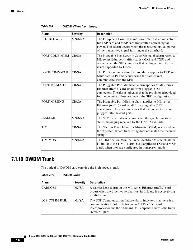
7.1.10 DWDM TrunkThe optical or DWDM card carrying the high-speed signal.
LO-TXPOWER MN/NSA The Equipment Low Transmit Power alarm is an indicator for TXP card and MXP card transmitted optical signal power. This alarm occurs when the measured optical power of the transmitted signal falls under the threshold.
PORT-CODE-MISM CR/SA The Pluggable Port Security Code Mismatch alarm refers to ML-series Ethernet (traffic) cards (MXP and TXP) and occurs when the SFP connector that is plugged into the card is not supported by Cisco.
PORT-COMM-FAIL CR/SA The Port Communication Failure alarm applies to TXP and MXP card SFPs and occurs when the card cannot communicate with the SFP.
PORT-MISMATCH CR/SA The Pluggable Port Mismatch alarm applies to ML-series Ethernet (traffic) card small form pluggable (SFP) connectors. The alarm indicates that the provisioned payload for the connector does not match the SFP configuration.
PORT-MISSING CR/SA The Pluggable Port Missing alarm applies to ML-series Ethernet (traffic) card small form pluggable (SFP) connectors. The alarm indicates that the connector is not plugged into the card port.
SSM-FAIL MN/NSA The SSM Failed alarm occurs when the synchronization status messaging received by the ONS 15454 fails.
TIM CR/SA The Section Trace Identifier Mismatch (TIM) occurs when the expected J0 path trace string does not match the received string.
TIM-MON MN/NSA The TIM Section Monitor Trace Identifier Mismatch alarm is similar to the TIM-P alarm, but it applies to TXP and MXP cards when they are configured in transparent mode.
Table 7-9 DWDM Client (continued)
Alarm Severity Description
Table 7-10 DWDM Trunk
Alarm Severity Description
CARLOSS MJ/SA A Carrier Loss alarm on the ML-series Ethernet (traffic) card occurs when the Ethernet port has lost its link and is not receiving a valid signal.
DSP-COMM-FAIL MJ/SA The DSP Communication Failure alarm indicates that there is a communications failure between an MXP or TXP card microprocessor and the on-board DSP chip that controls the trunk (DWDM) port.
7-6Cisco ONS 15454 and Cisco ONS 15327 TL1 Command Guide, R4.6
October 2008

Chapter 7 TL1 Alarms and ErrorsAlarms
DSP-FAIL MJ/SA The DSP Failure alarm indicates that a DSP-COMM-FAIL has persisted for an extended period on an MXP or TXP card and that the card is faulty.
EOC MJ/NSA The SONET Data Communications Channel (DCC) Termination Failure alarm occurs when the ONS 15454 loses its data communications channel.
GCC-EOC MJ/NSA The GCC Embedded Operation Channel Failure alarm applies to the OTN communication channel for TXP and MXP cards. It is raised when the channel cannot operate.
GE-OOSYNC CR/SA The Gigabit Ethernet Out of Sync alarm object applies to TXP cards when the Gigabit Ethernet signal is out of synchronization and is very similar to the SONET LOS alarm.
HI-LASERBIAS MN/NSA The Equipment High Transmit Laser Bias Current alarm is raised against the TXP and MXP card laser performance. The alarm indicates that the card laser has reached the maximum laser bias tolerance.
HI-RXPOWER MN/NSA The Equipment High Receive Power alarm is an indicator of the optical signal power that is transmitted to the TXP or MXP card.
HI-TXPOWER MN/NSA The Equipment High Transmit Power alarm is an indicator for TXP card and MXP card transmitted optical signal power. This alarm occurs when the measured optical power of the transmitted signal exceeds the threshold.
LOC CR/SA Loss of Fiber Continuity - Mux 32 occurs when G709 is turned on for trunk ports.
LOF CR/SA The Loss of Frame for the DWDM trunk applies to the trunk optical or electrical signal that is carried to TXP and MXP cards.
LOM CR/SA The optical transport unit (OTU) Loss of Multiframe alarm applies to MXP and TXP cards when the Multi Frame Alignment Signal (MFAS) overhead field is errored for more than five frames and persists for more than three milliseconds.
LO-RXPOWER MN/NSA The Equipment Low Receive Power alarm is an indicator for TXP card and MXP card received optical signal power. This alarm occurs when the measured optical power of the received signal falls under the threshold.
LOS CR/SA The Loss of Signal for the DWDM trunk applies to the trunk optical or electrical signal that is carried to TXP and MXP cards.
LO-TXPOWER MN/NSA The Equipment Low Transmit Power alarm is an indicator for TXP card and MXP card transmitted optical signal power. This alarm occurs when the measured optical power of the transmitted signal falls under the threshold.
Table 7-10 DWDM Trunk (continued)
Alarm Severity Description
7-7Cisco ONS 15454 and Cisco ONS 15327 TL1 Command Guide, R4.6
October 2008

Chapter 7 TL1 Alarms and ErrorsAlarms
7.1.11 ECNAn EC-N line on an EC-N card
7.1.12 ENVAn environmental alarm port
OTUK-LOF CR/SA The OTUK LOF alarm applies to TXP cards and MXP cards when G.709 monitoring is enabled for the cards. The alarm indicates that the card has lost frame delineation on the input data. Loss of frame occurs when the optical transport unit overhead frame alignment (FAS) area is errored for more than five frames and that the error persists more than three milliseconds.
PTIM MN/NSA The Payload Type Identifier Mismatch alarm occurs when there is a mismatch between the way the G.709 option is configured on MXP cards and TXP card at each end of the optical span.
SSM-FAIL MN/NSA The SSM Failed alarm occurs when the synchronization status messaging received by the ONS 15454 fails.
TIM CR/SA The Section Trace Identifier Mismatch (TIM) occurs when the expected J0 section trace string does not match the received section trace string.
TIM-MON MN/NSA The TIM Section Monitor Trace Identifier Mismatch alarm is similar to the TIM-P alarm, but it applies to TXP and MXP cards when they are configured in transparent mode.
WVL-MISMATCH MJ/SA The Equipment Wavelength Mismatch alarm applies to the TXP and MXP cards. It occurs when you provision the card in CTC with a wavelength that the card does not support.
Table 7-10 DWDM Trunk (continued)
Alarm Severity Description
Table 7-11 ECN
Alarm Severity Description
LOF CR/SA The EC-N LOF alarm occurs when a port on the reporting OC-N card has an LOF condition.
LOS CR/SA LOS on an EC-N port occurs when a SONET receiver detects an all-zero pattern for 10 microseconds or longer.
Table 7-12 ENV
Alarm Severity Description
EXT MN/NSA A Failure Detected External to the NE alarm occurs because an environmental alarm is present, for example, a door is open or flooding has occurred.
7-8Cisco ONS 15454 and Cisco ONS 15327 TL1 Command Guide, R4.6
October 2008
Chapter 7 TL1 Alarms and ErrorsAlarms
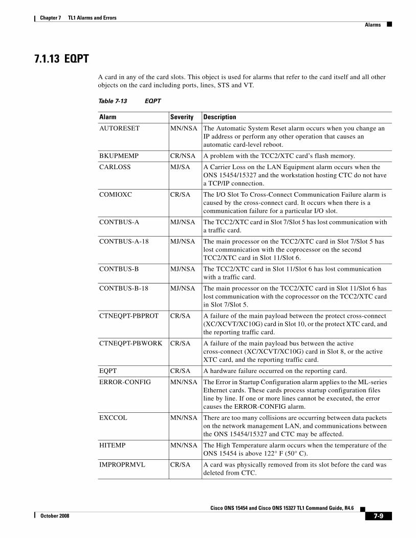
7.1.13 EQPTA card in any of the card slots. This object is used for alarms that refer to the card itself and all other objects on the card including ports, lines, STS and VT.
Table 7-13 EQPT
Alarm Severity Description
AUTORESET MN/NSA The Automatic System Reset alarm occurs when you change an IP address or perform any other operation that causes an automatic card-level reboot.
BKUPMEMP CR/NSA A problem with the TCC2/XTC card’s flash memory.
CARLOSS MJ/SA A Carrier Loss on the LAN Equipment alarm occurs when the ONS 15454/15327 and the workstation hosting CTC do not have a TCP/IP connection.
COMIOXC CR/SA The I/O Slot To Cross-Connect Communication Failure alarm is caused by the cross-connect card. It occurs when there is a communication failure for a particular I/O slot.
CONTBUS-A MJ/NSA The TCC2/XTC card in Slot 7/Slot 5 has lost communication with a traffic card.
CONTBUS-A-18 MJ/NSA The main processor on the TCC2/XTC card in Slot 7/Slot 5 has lost communication with the coprocessor on the second TCC2/XTC card in Slot 11/Slot 6.
CONTBUS-B MJ/NSA The TCC2/XTC card in Slot 11/Slot 6 has lost communication with a traffic card.
CONTBUS-B-18 MJ/NSA The main processor on the TCC2/XTC card in Slot 11/Slot 6 has lost communication with the coprocessor on the TCC2/XTC card in Slot 7/Slot 5.
CTNEQPT-PBPROT CR/SA A failure of the main payload between the protect cross-connect (XC/XCVT/XC10G) card in Slot 10, or the protect XTC card, and the reporting traffic card.
CTNEQPT-PBWORK CR/SA A failure of the main payload bus between the active cross-connect (XC/XCVT/XC10G) card in Slot 8, or the active XTC card, and the reporting traffic card.
EQPT CR/SA A hardware failure occurred on the reporting card.
ERROR-CONFIG MN/NSA The Error in Startup Configuration alarm applies to the ML-series Ethernet cards. These cards process startup configuration files line by line. If one or more lines cannot be executed, the error causes the ERROR-CONFIG alarm.
EXCCOL MN/NSA There are too many collisions are occurring between data packets on the network management LAN, and communications between the ONS 15454/15327 and CTC may be affected.
HITEMP MN/NSA The High Temperature alarm occurs when the temperature of the ONS 15454 is above 122° F (50° C).
IMPROPRMVL CR/SA A card was physically removed from its slot before the card was deleted from CTC.
7-9Cisco ONS 15454 and Cisco ONS 15327 TL1 Command Guide, R4.6
October 2008

Chapter 7 TL1 Alarms and ErrorsAlarms
7.1.14 ETHEREthernet, such as for straight-through (CAT 5) LAN cables.
7.1.15 EXTSYNCHBITS outgoing references (SYNC-BITS1, SYNC-BITS2)
MEA CR/SA The MEA alarm for equipment is reported against a card slot when the physical card inserted into a slot does not match the card type that is provisioned for that slot in CTC.
MEM-GONE MJ/NSA Data generated by software operations exceeds the memory capacity of the TCC2/XTC card.
MEM-LOW MN/NSA Data generated by software operations is close to exceeding the memory capacity of the TCC2/XTC card.
PEER-NORESPONSE
MJ/NSA The switch agent raises a Peer Card Not Responding alarm if either traffic card in a protection group does not receive a response to the peer status request message
PROTNA MN/NSA The Protection Unit Not Available is raised by an out-of-service protection when a TCC2/XTC or cross-connect card or port that is provisioned as part of a protection group is not available.
PWR-REDUN MN/NSA The Redundant Power Capability Lost alarm applies to cards (such as the TCC2 and newer optical cards) that have two built-in fuses. The alarm indicates that one of the fuses has blown, and must be serviced.
SFTWDOWN MN/NSA A Software Download in progress alarm occurs when the TCC2/XTC is downloading or transferring software.
SWMTXMOD CR/SA The Switching Matrix Module Failure alarm occurs on the cross-connect card or a traffic card. If the alarm reports against a traffic card, it means that the logic component on the cross-connect card is out of frame (OOF) with the logic component on the reporting traffic card.
Table 7-13 EQPT (continued)
Alarm Severity Description
Table 7-14 ETHER
Alarm Severity Description
CARLOSS MJ/SA A Carrier Loss on the LAN E-Series Ethernet (traffic) Card alarm is the data equivalent of an LOS (OC-N). The Ethernet card has lost its link and is not receiving a valid signal.
Table 7-15 EXTSYNCH
Alarm Severity Description
SYNCPRI MN/NSA A loss of the primary timing source (reference 1).
7-10Cisco ONS 15454 and Cisco ONS 15327 TL1 Command Guide, R4.6
October 2008

Chapter 7 TL1 Alarms and ErrorsAlarms
7.1.16 FANFan-tray assembly
7.1.17 FCMRFiber channel
SYNCSEC MN/NSA A loss of the secondary timing source (reference 2).
SYNCTHIRD MN/NSA A loss of the third timing source (reference 3).
Table 7-15 EXTSYNCH (continued)
Table 7-16 FAN
Alarm Severity Description
EQPT-MISS CR/SA Indicates the replaceable fan-tray assembly unit is missing or not fully inserted.
FAN CR/SA A problem with the fan-tray assembly.
FANDEGRADE MJ/NSA The Partial Fan Failure alarm is raised if fan speed for one of the fans in the fan-tray assembly falls below 500 RPM when read by a tachometry counter.
MEA CR/SA The MEA alarm is reported against the fan tray when a newer fan-tray assembly (15454-FTA3) with a 5 Amp fuse is used with an older shelf assembly or when an older fan tray with a 2 Amp fuse is used with a newer 10 Gbps compatible or ANSI shelf assembly (15454-SA-ANSI) that contains cards introduced in Release 3.1 or later.
MFGMEM CR/SA The manufacturing data memory failure alarm occurs if the ONS 15454 cannot access the data in the erasable programmable read-only memory (EEPROM).
Table 7-17 FCMR
Alarm Severity Description
INC-SIGLOSS MJ/NSA The Incoming Signal Loss on the Fibre Channel Interface alarm is raised when there is a signal loss at the local Fibre Channel port.
INC-SYNCLOSS MJ/NSA The Incoming Synchronization Loss on the Fibre Channel Interface alarm is raised when there is a synchronization error at the local Fibre Channel port.
TPTFAIL MJ/SA The Transport Fail alarm is raised against a local Fiber Channel port when the port receives another SONET error such as AIS-P, LOP-P, UNEQ-P, PLM-P, TIM-P, LOM (for VCat only), or SQM (for VCat only).
7-11Cisco ONS 15454 and Cisco ONS 15327 TL1 Command Guide, R4.6
October 2008

Chapter 7 TL1 Alarms and ErrorsAlarms
7.1.18 FUDCSONET byte user data channel
7.1.19 HDGE (G1000)High Density Gigabit Ethernet. Applies to G1000-4 cards.
7.1.20 L2SC (ML-Series)Layer 2 (and Layer 3 for ML-series) Switching Device
7.1.21 NBRNeighbor
Table 7-18 FUDC
Alarm Severity Description
LOS MN/NSA The LOS (FUDC) alarm is raised if there is a UDC circuit created on the AIC-I DCC port but the port is not receiving signal input.
Table 7-19 HDGE (G1000)
Alarm Severity Description
CARLOSS MJ/SA A carrier loss on the LAN G-series card is the data equivalent of an LOS (OC-N) alarm. The Ethernet card has lost its link and is not receiving a valid signal.
TPTFAIL MJ/SA The Transport (TPT) Layer Failure alarm for the G-series Ethernet (traffic) cards indicates a break in the end-to-end Ethernet link integrity feature of the G1000-4 cards. TPTFAIL indicates a far-end condition and not a problem with the port reporting TPTFAIL.
TUNDERRUN MJ/SA The Ethernet Transmit Underrun alarm is raised by a G1000-4 card when there is a major hardware fault on a port
Table 7-20 L2SC
Alarm Severity Description
CARLOSS MJ/SA A Carrier Loss alarm on the ML-series Ethernet (traffic) card is the data equivalent of the LOS (OCN) alarm. The Ethernet port has lost its link and is not receiving a valid signal.
TPTFAIL MJ/SA The TPT Layer Failure alarm for the ML-series Ethernet (traffic) cards indicates a break in the end-to-end POS link integrity feature of the ML-series POS cards. TPTFAIL indicates a far-end condition or misconfiguration of the POS port.
7-12Cisco ONS 15454 and Cisco ONS 15327 TL1 Command Guide, R4.6
October 2008

Chapter 7 TL1 Alarms and ErrorsAlarms
7.1.22 NEThe entire network element
7.1.23 NESYNCHRepresents the timing status of the NE
Table 7-21 NBR
Alarm Severity Description
RSVP-HELLODOWN MN/NSA The Resource Reservation Protocol (RSVP) Hello Down alarm occurs when the Hello protocol, which monitors UCP control channel status, is not available for reserving resources.
Table 7-22 NE
Alarm Severity Description
APC-DISABLED MJ/NSA The Automatic Power Control (APC) Disabled occurs when the information related to the number of channels is not reliable.
APC-FAIL MJ/NSA The APC Failure alarm occurs when APC has not been able to create a setpoint on a node because it has consumed all allocated power margins.
DATAFLT MN/NSA The TCC2/XTC exceeds its flash memory.
DBOSYNC MJ/NSA The standby TCC2/XTC “To be Active” database does not synchronize with the “Active” database on the active TCC2/XTC.
DUP-IDADDR MJ/NSA The Duplicate IP Address alarm indicates that the alarmed node’s IP address is already in use within the same DCC area.
DUP-NODENAME MJ/NSA The Duplicate Node Name alarm indicates that the alarmed node’s alphanumeric name is already being used within the same DCC area.
HITEMP CR/SA The High Temperature alarm occurs when the temperature of the ONS 15454/15327 is above 122° F (50° C).
OPTNTWMIS MJ/NSA The Optical Network Type Mismatch alarm is raised when DWDM nodes are not configured for the same type of network, either MetroCore and MetroAccess.
SNTP-HOST MN/NSA The SNTP (Simple Network Timing Protocol) Host Failure alarm indicates that an ONS node serving as an IP proxy for the other ONS nodes in the ring is not forwarding SNTP information to the other ONS nodes in the network.
SYSBOOT MJ/SA New software is booting on the TCC2/XTC card.
7-13Cisco ONS 15454 and Cisco ONS 15327 TL1 Command Guide, R4.6
October 2008
Chapter 7 TL1 Alarms and ErrorsAlarms
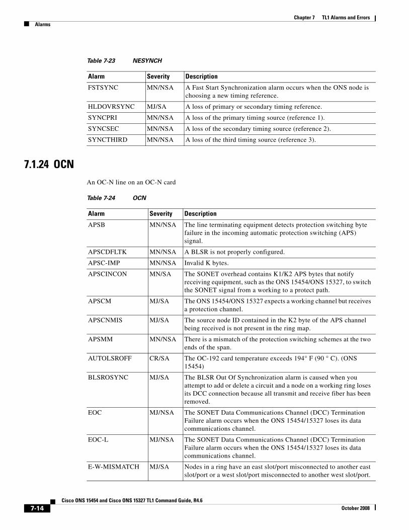
7.1.24 OCNAn OC-N line on an OC-N card
Table 7-23 NESYNCH
Alarm Severity Description
FSTSYNC MN/NSA A Fast Start Synchronization alarm occurs when the ONS node is choosing a new timing reference.
HLDOVRSYNC MJ/SA A loss of primary or secondary timing reference.
SYNCPRI MN/NSA A loss of the primary timing source (reference 1).
SYNCSEC MN/NSA A loss of the secondary timing source (reference 2).
SYNCTHIRD MN/NSA A loss of the third timing source (reference 3).
Table 7-24 OCN
Alarm Severity Description
APSB MN/NSA The line terminating equipment detects protection switching byte failure in the incoming automatic protection switching (APS) signal.
APSCDFLTK MN/NSA A BLSR is not properly configured.
APSC-IMP MN/NSA Invalid K bytes.
APSCINCON MN/SA The SONET overhead contains K1/K2 APS bytes that notify receiving equipment, such as the ONS 15454/ONS 15327, to switch the SONET signal from a working to a protect path.
APSCM MJ/SA The ONS 15454/ONS 15327 expects a working channel but receives a protection channel.
APSCNMIS MJ/SA The source node ID contained in the K2 byte of the APS channel being received is not present in the ring map.
APSMM MN/NSA There is a mismatch of the protection switching schemes at the two ends of the span.
AUTOLSROFF CR/SA The OC-192 card temperature exceeds 194° F (90 ° C). (ONS 15454)
BLSROSYNC MJ/SA The BLSR Out Of Synchronization alarm is caused when you attempt to add or delete a circuit and a node on a working ring loses its DCC connection because all transmit and receive fiber has been removed.
EOC MJ/NSA The SONET Data Communications Channel (DCC) Termination Failure alarm occurs when the ONS 15454/15327 loses its data communications channel.
EOC-L MJ/NSA The SONET Data Communications Channel (DCC) Termination Failure alarm occurs when the ONS 15454/15327 loses its data communications channel.
E-W-MISMATCH MJ/SA Nodes in a ring have an east slot/port misconnected to another east slot/port or a west slot/port misconnected to another west slot/port.
7-14Cisco ONS 15454 and Cisco ONS 15327 TL1 Command Guide, R4.6
October 2008

Chapter 7 TL1 Alarms and ErrorsAlarms
7.1.25 OSCRINGOptical service channel ring
7.1.26 PWRPower
EXTRA-TRAF-PREEMPT
MJ/SA An Extra Traffic Preempted alarm occurs on OC-N cards in two-fiber and four-fiber BLSRs because low-priority traffic directed to the protect system has been preempted by a working system protection switch.
FEPRLF MN/NSA an APS switching channel SF occurs on the protect card coming into the node.
KBYTE-APS-CHANNEL-FAILURE
MN/NSA The APS Channel Failure alarm is raised when there a span provisioned for different APS channels on each side.
LASEREOL MN/NSA The Laser Approaching End of Life alarm applies to TXP and MXP cards and occurs when the laser in the card will need to be replaced.
LOF CR/SA A port on the reporting OC-N card or TXP card has an LOF condition.
LOS CR/SA A SONET receiver detects an all-zero pattern for 10 microseconds or longer.
SSM-FAIL MN/NSA Synchronization status messaging received by the ONS 15454/ONS 15327 fails.
Table 7-24 OCN (continued)
Alarm Severity Description
Table 7-25 OSCRING
Alarm Severity Description
RING-ID-MIS MJ/NSA (Applicable to DWDM nodes only) The Ring ID Mismatch refers to the ring OSC in APC and occurs when a ring ID does not match other detectable node ring IDs.
Table 7-26 PWR
Alarm Severity Description
BAT-FAIL MJ/SA The Battery Fail alarm occurs when one of the two power supplies (A or B) is not detected.
EHIBATVG MJ/SA The Extreme High Voltage Battery alarm occurs in a –48 Vdc environment when a battery lead’s input voltage exceeds the extreme high power threshold.
7-15Cisco ONS 15454 and Cisco ONS 15327 TL1 Command Guide, R4.6
October 2008
Chapter 7 TL1 Alarms and ErrorsAlarms
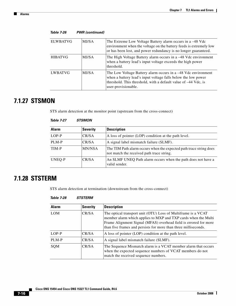
7.1.27 STSMONSTS alarm detection at the monitor point (upstream from the cross-connect)
7.1.28 STSTERMSTS alarm detection at termination (downstream from the cross-connect)
ELWBATVG MJ/SA The Extreme Low Voltage Battery alarm occurs in a –48 Vdc environment when the voltage on the battery feeds is extremely low or has been lost, and power redundancy is no longer guaranteed.
HIBATVG MJ/SA The High Voltage Battery alarm occurs in a –48 Vdc environment when a battery lead’s input voltage exceeds the high power threshold.
LWBATVG MJ/SA The Low Voltage Battery alarm occurs in a –48 Vdc environment when a battery lead’s input voltage falls below the low power threshold. This threshold, with a default value of –44 Vdc, is user-provisionable.
Table 7-26 PWR (continued)
Table 7-27 STSMON
Alarm Severity Description
LOP-P CR/SA A loss of pointer (LOP) condition at the path level.
PLM-P CR/SA A signal label mismatch failure (SLMF).
TIM-P MN/NSA The TIM Path alarm occurs when the expected path trace string does not match the received path trace string.
UNEQ-P CR/SA An SLMF UNEQ Path alarm occurs when the path does not have a valid sender.
Table 7-28 STSTERM
Alarm Severity Description
LOM CR/SA The optical transport unit (OTU) Loss of Multiframe is a VCAT member alarm which applies to MXP and TXP cards when the Multi Frame Alignment Signal (MFAS) overhead field is errored for more than five frames and persists for more than three milliseconds.
LOP-P CR/SA A loss of pointer (LOP) condition at the path level.
PLM-P CR/SA A signal label mismatch failure (SLMF).
SQM CR/SA The Sequence Mismatch alarm is a VCAT member alarm that occurs when the expected sequence numbers of VCAT members do not match the received sequence numbers.
7-16Cisco ONS 15454 and Cisco ONS 15327 TL1 Command Guide, R4.6
October 2008
Chapter 7 TL1 Alarms and ErrorsAlarms
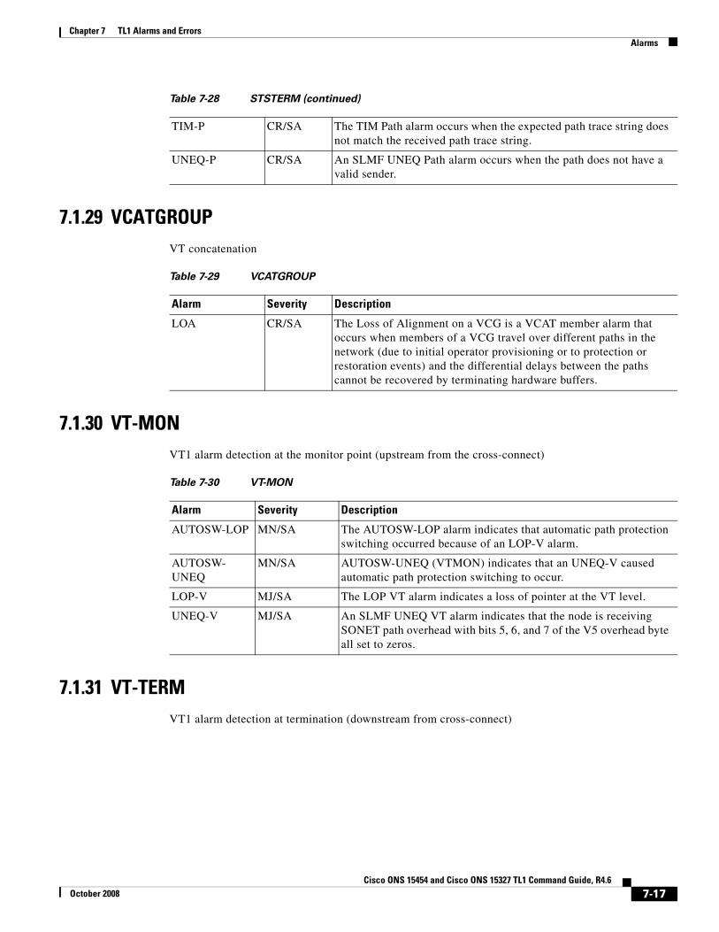
7.1.29 VCATGROUPVT concatenation
7.1.30 VT-MONVT1 alarm detection at the monitor point (upstream from the cross-connect)
7.1.31 VT-TERMVT1 alarm detection at termination (downstream from cross-connect)
TIM-P CR/SA The TIM Path alarm occurs when the expected path trace string does not match the received path trace string.
UNEQ-P CR/SA An SLMF UNEQ Path alarm occurs when the path does not have a valid sender.
Table 7-28 STSTERM (continued)
Table 7-29 VCATGROUP
Alarm Severity Description
LOA CR/SA The Loss of Alignment on a VCG is a VCAT member alarm that occurs when members of a VCG travel over different paths in the network (due to initial operator provisioning or to protection or restoration events) and the differential delays between the paths cannot be recovered by terminating hardware buffers.
Table 7-30 VT-MON
Alarm Severity Description
AUTOSW-LOP MN/SA The AUTOSW-LOP alarm indicates that automatic path protection switching occurred because of an LOP-V alarm.
AUTOSW-UNEQ
MN/SA AUTOSW-UNEQ (VTMON) indicates that an UNEQ-V caused automatic path protection switching to occur.
LOP-V MJ/SA The LOP VT alarm indicates a loss of pointer at the VT level.
UNEQ-V MJ/SA An SLMF UNEQ VT alarm indicates that the node is receiving SONET path overhead with bits 5, 6, and 7 of the V5 overhead byte all set to zeros.
7-17Cisco ONS 15454 and Cisco ONS 15327 TL1 Command Guide, R4.6
October 2008
Chapter 7 TL1 Alarms and ErrorsConditions
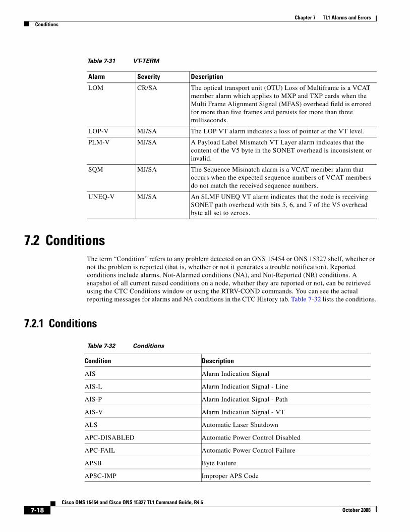
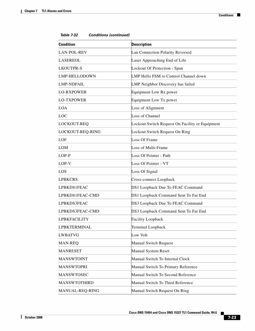
7.2 ConditionsThe term “Condition” refers to any problem detected on an ONS 15454 or ONS 15327 shelf, whether or not the problem is reported (that is, whether or not it generates a trouble notification). Reported conditions include alarms, Not-Alarmed conditions (NA), and Not-Reported (NR) conditions. A snapshot of all current raised conditions on a node, whether they are reported or not, can be retrieved using the CTC Conditions window or using the RTRV-COND commands. You can see the actual reporting messages for alarms and NA conditions in the CTC History tab. Table 7-32 lists the conditions.
7.2.1 Conditions
Table 7-31 VT-TERM
Alarm Severity Description
LOM CR/SA The optical transport unit (OTU) Loss of Multiframe is a VCAT member alarm which applies to MXP and TXP cards when the Multi Frame Alignment Signal (MFAS) overhead field is errored for more than five frames and persists for more than three milliseconds.
LOP-V MJ/SA The LOP VT alarm indicates a loss of pointer at the VT level.
PLM-V MJ/SA A Payload Label Mismatch VT Layer alarm indicates that the content of the V5 byte in the SONET overhead is inconsistent or invalid.
SQM MJ/SA The Sequence Mismatch alarm is a VCAT member alarm that occurs when the expected sequence numbers of VCAT members do not match the received sequence numbers.
UNEQ-V MJ/SA An SLMF UNEQ VT alarm indicates that the node is receiving SONET path overhead with bits 5, 6, and 7 of the V5 overhead byte all set to zeroes.
Table 7-32 Conditions
Condition Description
AIS Alarm Indication Signal
AIS-L Alarm Indication Signal - Line
AIS-P Alarm Indication Signal - Path
AIS-V Alarm Indication Signal - VT
ALS Automatic Laser Shutdown
APC-DISABLED Automatic Power Control Disabled
APC-FAIL Automatic Power Control Failure
APSB Byte Failure
APSC-IMP Improper APS Code
7-18Cisco ONS 15454 and Cisco ONS 15327 TL1 Command Guide, R4.6
October 2008

Chapter 7 TL1 Alarms and ErrorsConditions
APSCDFLTK Default K Byte
APSCINCON Inconsistent APS Code
APSCM Protection Switching Channel Match Failure
APSCNMIS Node Id Mismatch
APSIMP APS Invalid Mode
APSMM Automatic Protection Switch Mode Mismatch
AS-CMD Alarms Suppressed By User Command
AS-MT Alarms Suppressed For Maintenance
AU-LOF LOF - Administration Unit - Loss of Multi Frame
AUD-LOG-LOSS Audit Log 100 Percent Full - Oldest records will be lost
AUD-LOG-LOW Audit Log 80 Percent Full
AUTOLSROFF Automatic Laser Shutoff Due To High Temperature
AUTORESET Automatic System Reset
AUTOSW-AIS Automatic path protection Switch Caused By AIS
AUTOSW-LOP Automatic path protection Switch Caused By LOP
AUTOSW-PDI Automatic path protection Switch Caused By PDI
AUTOSW-SDBER Automatic path protection Switch Caused By SDBER
AUTOSW-SFBER Automatic path protection Switch Caused By SFBER
AUTOSW-UNEQ Automatic path protection Switch Caused By UNEQ
BAT-FAIL Battery Failure
BKUPMEMP Primary Non-Volatile Backup Memory Failure
BLSROSYNC BLSR Out Of Sync
CARLOSS Carrier Loss On The LAN
CKTDOWN Signaling Unable to setup circuit
CLDRESTART Cold Restart
COMIOXC IO Slot To XCON Communication Failure
COMM-FAIL Plug-in Module Communication Failure
CONTBUS-A-18 TCC A To DCC A Processor Communication Failure
CONTBUS-B-18 TCC B To DCC B Processor Communication Failure
CONTBUS_A Controller A To Shelf Slot Communication Failure
CONTBUS_B Controller B To Shelf Slot Communication Failure
Table 7-32 Conditions (continued)
Condition Description
7-19Cisco ONS 15454 and Cisco ONS 15327 TL1 Command Guide, R4.6
October 2008

Chapter 7 TL1 Alarms and ErrorsConditions
CTNEQPT-MISMATCH Connection Equipment Mismatch
CTNEQPT-PBPROT Interconnection Equipment Failure - Protect XC Payload Bus
CTNEQPT-PBWORK Interconnection Equipment Failure - Working XC Payload Bus
DATAFLT Software Fault - Data Integrity Fault
DBOSYNC Standby Database Out of Sync
DS3-MISM DS3 Frame Format Mismatch
DSP-COMM-FAIL DSP Communication Failure
DSP-FAIL DSP Failure
DUP-IPADDR IP address already in use within the same DCC Area
DUP-NODENAME Node name already in use within the same DCC Area
E-W-MISMATCH Both Ends Of Fiber Provisioned As East Or Both As West
EHIBATVG Extreme High Volt
ELWBATVG Extreme Low Volt
EOC SDCC Termination Failure
EOC-L Line DCC Termination Failure
EQPT Equipment Failure
EQPT-MISS Replaceable Equipment/Unit is Missing
ERFI-P-CONN Enhanced Remote Failure Indication - Path - Connectivity
ERFI-P-PAYLD Enhanced Remote Failure Indication - Path - Payload
ERFI-P-SRVR Enhanced Remote Failure Indication - Path - Server
ERROR-CONFIG Error in Startup Config
ETH-LINKLOSS Rear Panel Ethernet Link Removed
EXCCOL Excess Collisions On The LAN
EXERCISE-RING-FAIL Exercise Request on Ring Failed
EXERCISE-RING-REQ Exercise Request on Ring
EXERCISE-SPAN-FAIL Exercise Request on Span Failed
EXERCISE-SPAN-REQ Exercise Request on Span
EXT Failure Detected External To The NE
EXTRA-TRAF-PREEMPT Extra Traffic Preempted
FAILTOSW Failure To Switch To Protection
Table 7-32 Conditions (continued)
Condition Description
7-20Cisco ONS 15454 and Cisco ONS 15327 TL1 Command Guide, R4.6
October 2008
Chapter 7 TL1 Alarms and ErrorsConditions
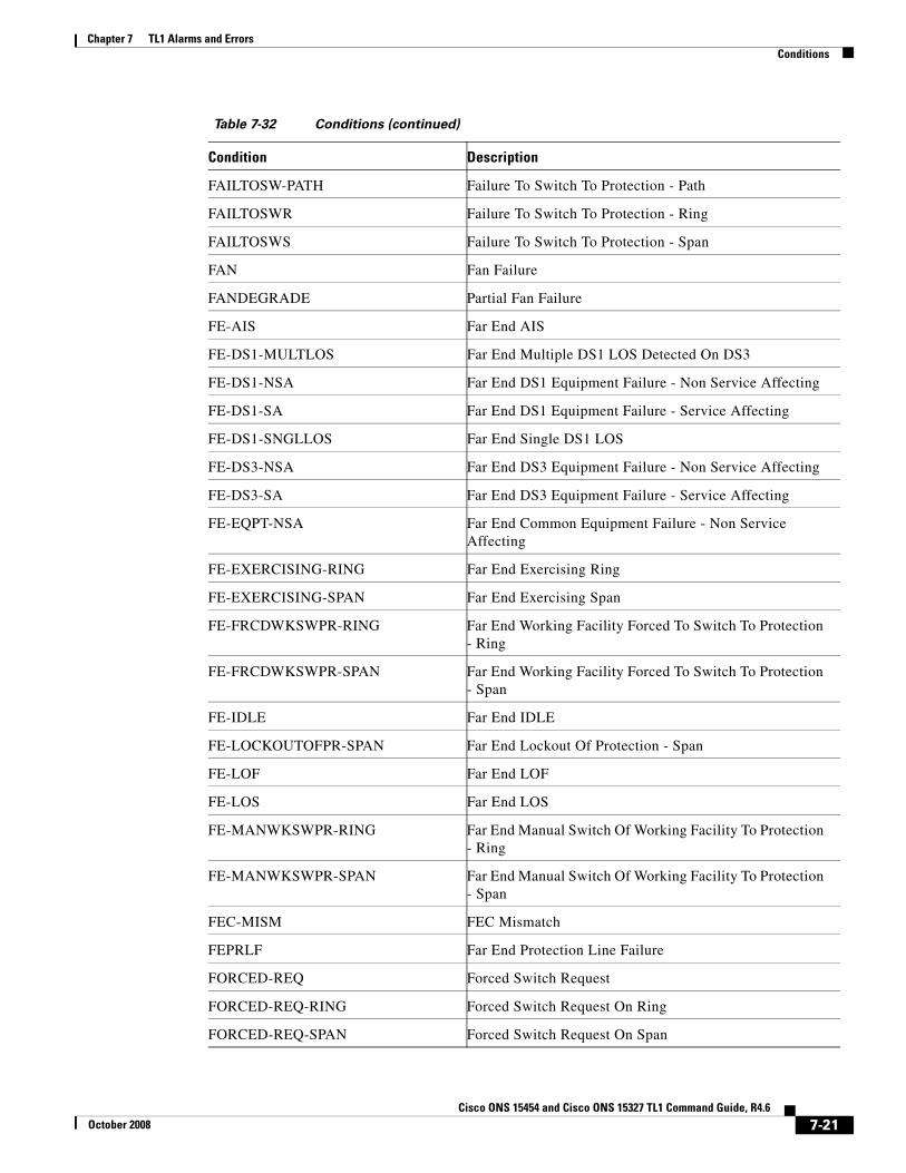
FAILTOSW-PATH Failure To Switch To Protection - Path
FAILTOSWR Failure To Switch To Protection - Ring
FAILTOSWS Failure To Switch To Protection - Span
FAN Fan Failure
FANDEGRADE Partial Fan Failure
FE-AIS Far End AIS
FE-DS1-MULTLOS Far End Multiple DS1 LOS Detected On DS3
FE-DS1-NSA Far End DS1 Equipment Failure - Non Service Affecting
FE-DS1-SA Far End DS1 Equipment Failure - Service Affecting
FE-DS1-SNGLLOS Far End Single DS1 LOS
FE-DS3-NSA Far End DS3 Equipment Failure - Non Service Affecting
FE-DS3-SA Far End DS3 Equipment Failure - Service Affecting
FE-EQPT-NSA Far End Common Equipment Failure - Non Service Affecting
FE-EXERCISING-RING Far End Exercising Ring
FE-EXERCISING-SPAN Far End Exercising Span
FE-FRCDWKSWPR-RING Far End Working Facility Forced To Switch To Protection - Ring
FE-FRCDWKSWPR-SPAN Far End Working Facility Forced To Switch To Protection - Span
FE-IDLE Far End IDLE
FE-LOCKOUTOFPR-SPAN Far End Lockout Of Protection - Span
FE-LOF Far End LOF
FE-LOS Far End LOS
FE-MANWKSWPR-RING Far End Manual Switch Of Working Facility To Protection - Ring
FE-MANWKSWPR-SPAN Far End Manual Switch Of Working Facility To Protection - Span
FEC-MISM FEC Mismatch
FEPRLF Far End Protection Line Failure
FORCED-REQ Forced Switch Request
FORCED-REQ-RING Forced Switch Request On Ring
FORCED-REQ-SPAN Forced Switch Request On Span
Table 7-32 Conditions (continued)
Condition Description
7-21Cisco ONS 15454 and Cisco ONS 15327 TL1 Command Guide, R4.6
October 2008

Chapter 7 TL1 Alarms and ErrorsConditions
FRCDSWTOINT Forced Switch To Internal Clock
FRCDSWTOPRI Forced Switch To Primary Reference
FRCDSWTOSEC Forced Switch To Second Reference
FRCDSWTOTHIRD Forced Switch To Third Reference
FRNGSYNC Free Running Synchronization Mode
FSTSYNC Fast Start Synchronization Mode
FULLPASSTHR-BI Bidirectional Full Pass Through Is Active
GCC-EOC GCC Termination Failure
GE-OOSYNC GigaBit Ethernet Out of Sync
HI-LASERBIAS Equipment High Laser Bias
HI-RXPOWER Equipment High Rx power
HI-TXPOWER Equipment High Tx power
HIBATVG High Volt
HITEMP High Temperature
HLDOVRSYNC Holdover Synchronization Mode
I-HITEMP Industrial High Temperature
IMPROPRMVL Improper Removal
INC-GFP-OUTOFFRAME Out Of Frame Detected by GFP Receiver
INC-GFP-SIGLOSS Client Signal Loss Frames Detected by GFP Receiver
INC-ISD DS3 Idle Condition
INC-SIGLOSS Incoming Signal Loss on Fibre Channel Interface
INC-SYNCLOSS Incoming Synchronization Loss on Fibre Channel Interface
INC_GFP_SYNCLOSS Client Synchronization Loss Frames Detected by GFP Receiver
INHSWPR Inhibit Switch To Protect Request On Equipment
INHSWWKG Inhibit Switch To Working Request On Equipment
INTRUSION-PSWD Security Intrusion Attempt Detected - See Audit Log
INVMACADR Invalid MAC Address
IOSCFGCOPY Ios Config Copy In Progress
KB-PASSTHR K Bytes Pass Through Is Active
KBYTE-APS-CHANNEL-FAILURE Kbyte Channel Failure
Table 7-32 Conditions (continued)
Condition Description
7-22Cisco ONS 15454 and Cisco ONS 15327 TL1 Command Guide, R4.6
October 2008
Chapter 7 TL1 Alarms and ErrorsConditions
LAN-POL-REV Lan Connection Polarity Reversed
LASEREOL Laser Approaching End of Life
LKOUTPR-S Lockout Of Protection - Span
LMP-HELLODOWN LMP Hello FSM to Control Channel down
LMP-NDFAIL LMP Neighbor Discovery has failed
LO-RXPOWER Equipment Low Rx power
LO-TXPOWER Equipment Low Tx power
LOA Loss of Alignment
LOC Loss of Channel
LOCKOUT-REQ Lockout Switch Request On Facility or Equipment
LOCKOUT-REQ-RING Lockout Switch Request On Ring
LOF Loss Of Frame
LOM Loss of Multi-Frame
LOP-P Loss Of Pointer - Path
LOP-V Loss Of Pointer - VT
LOS Loss Of Signal
LPBKCRS Cross-connect Loopback
LPBKDS1FEAC DS1 Loopback Due To FEAC Command
LPBKDS1FEAC-CMD DS1 Loopback Command Sent To Far End
LPBKDS3FEAC DS3 Loopback Due To FEAC Command
LPBKDS3FEAC-CMD DS3 Loopback Command Sent To Far End
LPBKFACILITY Facility Loopback
LPBKTERMINAL Terminal Loopback
LWBATVG Low Volt
MAN-REQ Manual Switch Request
MANRESET Manual System Reset
MANSWTOINT Manual Switch To Internal Clock
MANSWTOPRI Manual Switch To Primary Reference
MANSWTOSEC Manual Switch To Second Reference
MANSWTOTHIRD Manual Switch To Third Reference
MANUAL-REQ-RING Manual Switch Request On Ring
Table 7-32 Conditions (continued)
Condition Description
7-23Cisco ONS 15454 and Cisco ONS 15327 TL1 Command Guide, R4.6
October 2008

Chapter 7 TL1 Alarms and ErrorsConditions
MANUAL-REQ-SPAN Manual Switch Request On Span
MEA Mismatch Of Equipment And Attributes
MEM-GONE Free Memory On Card Near Zero
MEM-LOW Free Memory On Card Very Low
MFGMEM Manufacturing Data Memory (EEPROM Failure
NO-CONFIG No Startup Config
NTWTPINC Network Topology Incomplete
OCHNC-ACTIV-FAIL Optical Channel Activation Failure
OCHNC-DEACTIV-FAIL Optical Channel De-Activation Failure
OCHNC-FAIL Optical Channel Connection Failure
OCHNC-INC Optical Channel Incomplete
ODUK-AIS-PM ODUk: Alarm Indication Signal
ODUK-BDI-PM ODUk: PM Backward Defect Indication
ODUK-LCK-PM ODUk: Locked Defect - PM
ODUK-OCI-PM ODUk: Open Connection Indication
ODUK-SD-PM ODUk: Signal Degrade
ODUK-SF-PM ODUk: Signal Failure
ODUK-TIM-PM ODUk: Trail Trace Identifier Mismatch
OOU-TPT Out of Use - Transport Failure
OPTNTWMIS Optical Network Type Mismatch
OTUK-AIS OTUk: Alarm Indication Signal
OTUK-BDI OTUk: Backward Defect Indication
OTUK-LOF OTUk: Loss Of Frame
OTUK-SD OTUk: Signal Degrade
OTUK-SF OTUk: Signal Failure
OTUK-TIM OTUk: Trail Trace Identifier Mismatch
OUT-OF-SYNC 8B10B Out of Sync
PDI-P Payload Defect Indication - Path
PEER-NORESPONSE Peer Card Not Responding
PLM-P Payload Label Mismatch - Path
PLM-V Signal Label Mismatch Failure - Payload Label Mismatch - VT
Table 7-32 Conditions (continued)
Condition Description
7-24Cisco ONS 15454 and Cisco ONS 15327 TL1 Command Guide, R4.6
October 2008

Chapter 7 TL1 Alarms and ErrorsConditions
PORT-CODE-MISM Pluggable Port security code mismatch
PORT-COMM-FAIL Module Communication Failure
PORT-MISMATCH Pluggable Port rate mismatch
PORT-MISSING Pluggable Port missing
PRC-DUPID Duplicate Node ID
PROTNA Protection Unit Not Available
PTIM Payload Type Identifier Mismatch
PWR-REDUN Redundant Power Capability Lost
RAI Remote Alarm Indication
RCVR-MISS Facility Termination Equipment - Receiver Missing
RFI Remote Failure Indication
RFI-L Remote Failure Indication - Line
RFI-P One-Bit Remote Failure Indication - Path
RFI-V Remote Failure Indication - VT
RING-ID-MIS Ring Id Mismatch
RING-MISMATCH Far End Of Fiber Is Provisioned With Different Ring ID
RING-SW-EAST Ring Switch Is Active On The East Side
RING-SW-WEST Ring Switch Is Active On The West Side
RSVP-HELLODOWN RSVP Hello FSM to Neighbor down
RUNCFG-SAVENEED Need to Save Running Config
SD Signal Degrade
SD-L BER Threshold Exceeded For Signal Degrade - Line
SD-P BER Threshold Exceeded For Signal Degrade - Path
SF Signal Failure
SF-L BER Threshold Exceeded For Signal Failure - Line
SF-P BER Threshold Exceeded For Signal Failure - Path
SFTWDOWN Software Download In Progress
SNTP-HOST SNTP Host Failure
SPAN-SW-EAST Span Switch Is Active On The East Side
SPAN-SW-WEST Span Switch Is Active On The West Side
SQM Sequence Mismatch
Table 7-32 Conditions (continued)
Condition Description
7-25Cisco ONS 15454 and Cisco ONS 15327 TL1 Command Guide, R4.6
October 2008

Chapter 7 TL1 Alarms and ErrorsConditions
SQUELCH Ring Is Squelching Traffic
SQUELCHED Equipment Squelched
SSM-DUS Do Not Use For Synchronization
SSM-FAIL Failed To Receive Synchronization Status Message
SSM-LNC G812 - Local Node Clock traceable
SSM-OFF Synchronization Status Messages Are Disabled On This Interface
SSM-PRC G811 - Primary Reference Clock traceable
SSM-PRS Stratum 1 Primary Reference Source Traceable
SSM-RES Reserved For Network Synchronization Use
SSM-SDH-TN G812 - Transit Node Clock traceable
SSM-SETS G813 - Synchronous Equipment Timing Source traceable
SSM-SMC SONET Minimum Clock Traceable
SSM-ST2 Stratum 2 Traceable
SSM-ST3 Stratum 3 Traceable
SSM-ST3E Stratum 3E Traceable
SSM-ST4 Stratum 4 Traceable
SSM-STU Synchronized - Traceability Unknown
SSM-TNC Transit Node Clock Traceable
SWMTXMOD Switching Matrix Module Failure
SWTOPRI Switch To Primary Reference
SWTOSEC Switch To Second Reference
SWTOTHIRD Switch To Third Reference
SYNC-FREQ Synchronization Reference Frequency Out Of Bounds
SYNCPRI Primary Synchronization Reference Failure
SYNCSEC Secondary Synchronization Reference Failure
SYNCTHIRD Third Synchronization Reference Failure
SYSBOOT System Reboot
TIM TIM Section - Trace Identifier Mismatch Failure
TIM-MON TIM Section Monitor - Trace Identifier Mismatch Failure
TIM-P STS Path Trace Identifier Mismatch
TPTFAIL Transport layer failure
Table 7-32 Conditions (continued)
Condition Description
7-26Cisco ONS 15454 and Cisco ONS 15327 TL1 Command Guide, R4.6
October 2008

Chapter 7 TL1 Alarms and ErrorsErrors
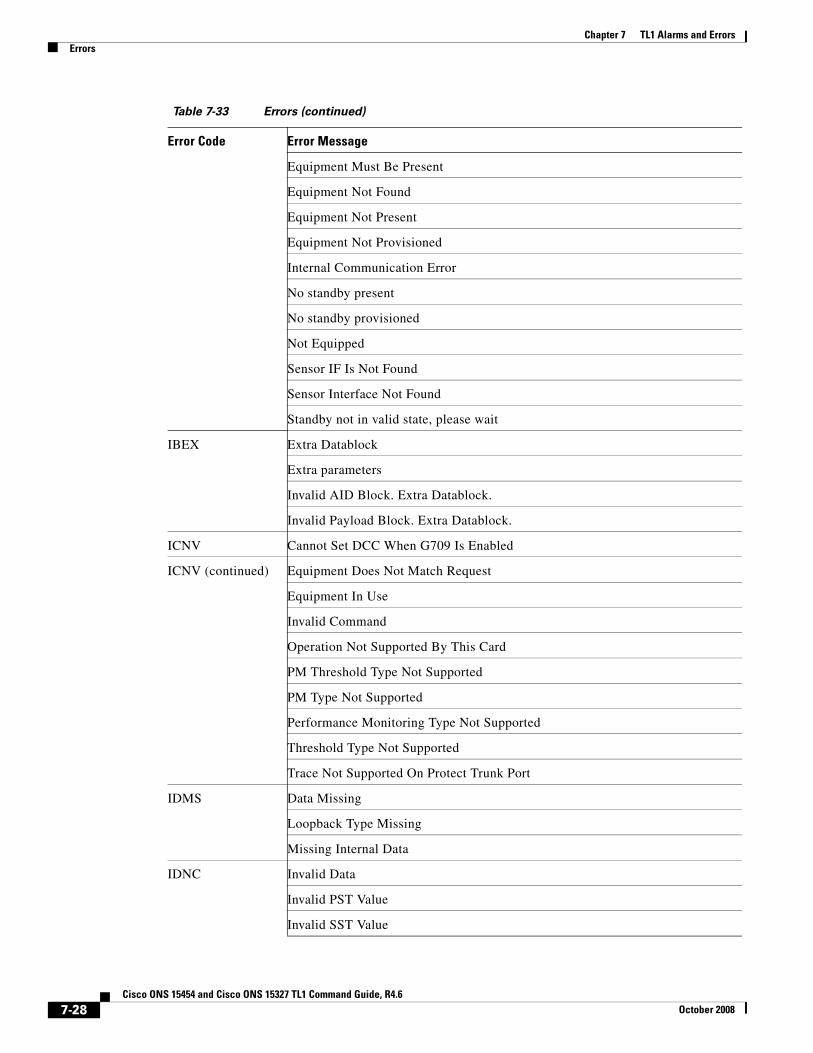
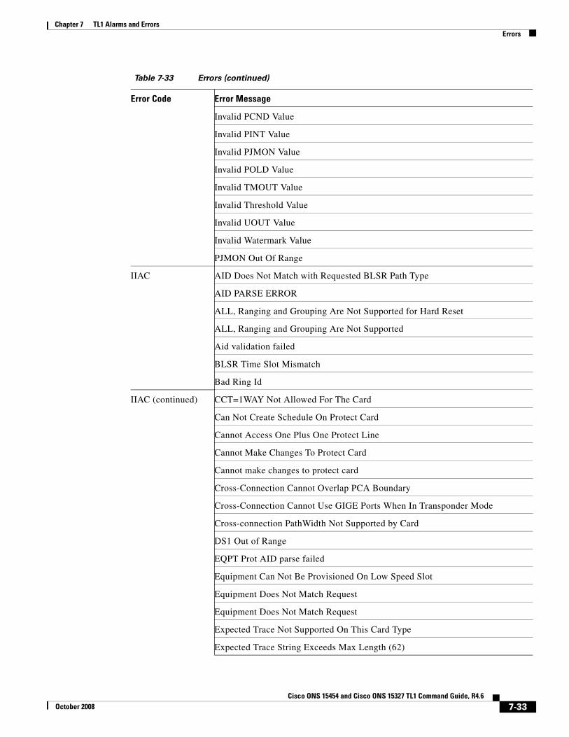
7.3 ErrorsErrors may be generated by any command or command response message. You can find errors listed by error code in Table 7-33 on page 7-27. The format of an error message is as follows:
SID DATE TIMEM CTAG DENY <ERRCDE> /* <ERRMSG> */;
7.3.1 Errors Listed by Error CodeError Code SONET Error Messages
TRMT Transmit Failure
TRMT-MISS Facility Termination Equipment - Transmitter Missing
TUNDERRUN Ether tx underrun
TX-AIS Alarm Indication Signal in TX
TX-RAI Remote Alarm Indication in TX
UNC-WORD FEC Uncorrected Word
UNEQ-P Unequipped - Path
UNEQ-V Signal Label Mismatch Failure - Unequipped VT
VCG-DEG VCAT Group Degraded
VCG-DOWN VCAT Group Down
WKSWPR Switched To Protection
WTR Wait To Restore
WVL-MISMATCH Equipment Wavelength Mismatch
Table 7-32 Conditions (continued)
Condition Description
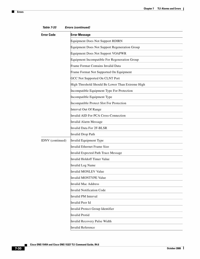
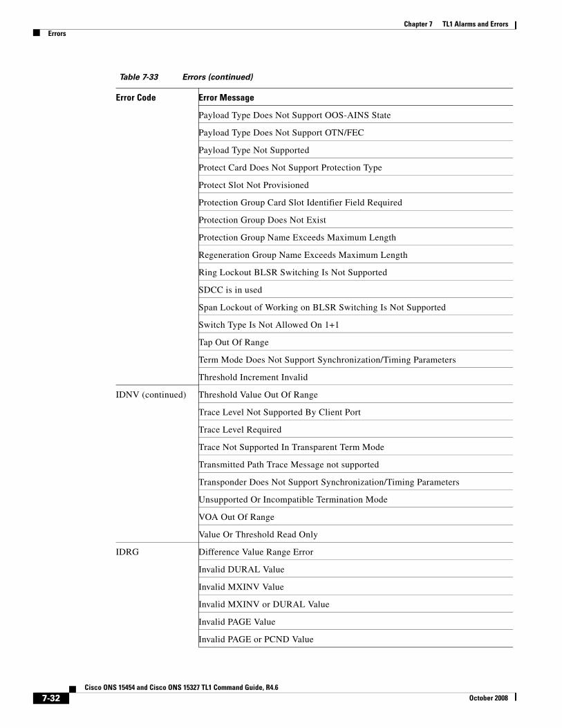
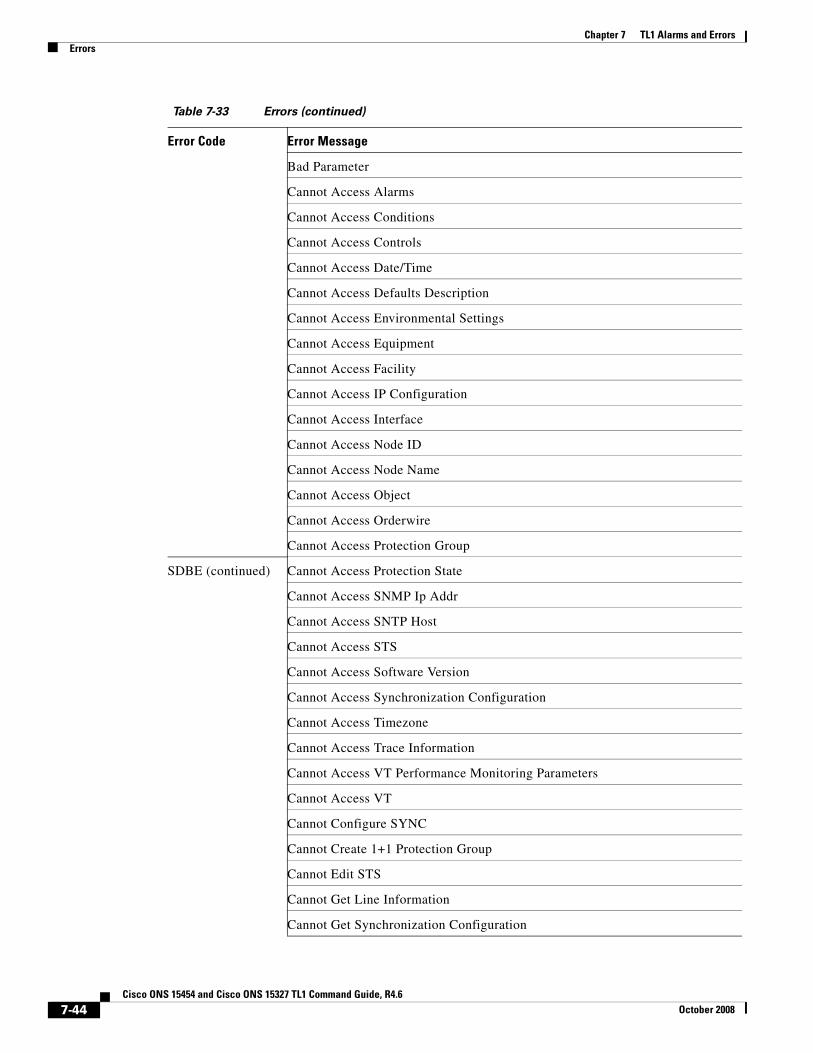
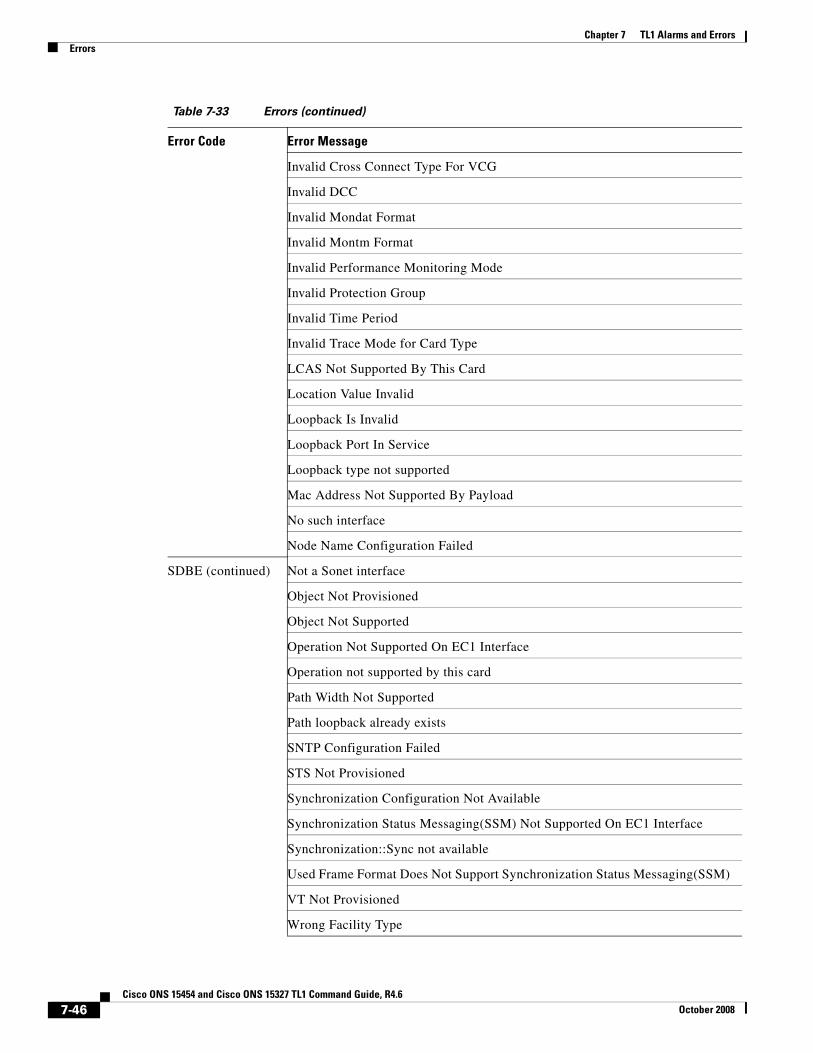
Table 7-33 Errors
Error Code Error Message
ENEQ At Least One Equipment Is Not Plugged
Communication Failed
Control Not Provisioned
EnvControl IF Is Not Found
Environmental Control Interface Not Found
7-27Cisco ONS 15454 and Cisco ONS 15327 TL1 Command Guide, R4.6
October 2008
Chapter 7 TL1 Alarms and ErrorsErrors
Equipment Must Be Present
Equipment Not Found
Equipment Not Present
Equipment Not Provisioned
Internal Communication Error
No standby present
No standby provisioned
Not Equipped
Sensor IF Is Not Found
Sensor Interface Not Found
Standby not in valid state, please wait
IBEX Extra Datablock
Extra parameters
Invalid AID Block. Extra Datablock.
Invalid Payload Block. Extra Datablock.
ICNV Cannot Set DCC When G709 Is Enabled
ICNV (continued) Equipment Does Not Match Request
Equipment In Use
Invalid Command
Operation Not Supported By This Card
PM Threshold Type Not Supported
PM Type Not Supported
Performance Monitoring Type Not Supported
Threshold Type Not Supported
Trace Not Supported On Protect Trunk Port
IDMS Data Missing
Loopback Type Missing
Missing Internal Data
IDNC Invalid Data
Invalid PST Value
Invalid SST Value
Table 7-33 Errors (continued)
Error Code Error Message
7-28Cisco ONS 15454 and Cisco ONS 15327 TL1 Command Guide, R4.6
October 2008

Chapter 7 TL1 Alarms and ErrorsErrors
PRI source cannot be INTERNAL when SEC source is not INTERNAL
PRI source cannot be INTERNAL when THIRD is not INTERNAL
Primary Source Cannot Be INTERNAL When Secondary Source Is Not INTERNAL
Primary Source Cannot Be INTERNAL When Third Source Is Not INTERNAL
SEC source cannot be INTERNAL when THIRD is not INTERNAL
Secondary Source Cannot Be INTERNAL When Third Source Is Not INTERNAL
Third source must be INTERNAL
IDNV 2F-BLSR Architecture Does Not Permit Manual/Forced Span Switching
AUTO ALS Mode Not Allowed With Digital Wrapper Disabled
AUTO Trace Mode Not Allowed
Alarm Message Must Be Enclosed Within a Pair of Quotes
Alarm Message Required for MISC
At least an XC10G XC card is needed for this equipment type
Cannot Access DCC
Cannot Change Protection Type
IDNV (continued) Cannot Edit NAME When Regeneration Group Not Present
CMDMDE Only Applicable when Creating/Deleting Protection Group
Command Not Valid On Protect Card
Configuration Does Not Support AUTO ALS Mode
DCC Not Supported In Transparent Term Mode
DCC is in used
Description Cannot Have More Than 64 Characters
Description cannot be more than 32 characters
Edit FMT on an Invalid Card
Edit FMT with an Invalid Data
Edit Line Code Failed
Edit Line Code on an Invalid Card
Equipment Does Not Support CALOPWR
Equipment Does Not Support EXPWLEN
Equipment Does Not Support Payload Type
Table 7-33 Errors (continued)
Error Code Error Message
7-29Cisco ONS 15454 and Cisco ONS 15327 TL1 Command Guide, R4.6
October 2008
Chapter 7 TL1 Alarms and ErrorsErrors
Equipment Does Not Support RDIRN
Equipment Does Not Support Regeneration Group
Equipment Does Not Support VOAPWR
Equipment Incompatible For Regeneration Group
Frame Format Contains Invalid Data
Frame Format Not Supported On Equipment
GCC Not Supported On CLNT Port
High Threshold Should Be Lower Than Extreme High
Incompatible Equipment Type For Protection
Incompatible Equipment Type
Incompatible Protect Slot For Protection
Interval Out Of Range
Invalid AID For PCA Cross-Connection
Invalid Alarm Message
Invalid Data For 2F-BLSR
Invalid Drop Path
IDNV (continued) Invalid Equipment Type
Invalid Ethernet Frame Size
Invalid Expected Path Trace Message
Invalid Holdoff Timer Value
Invalid Log Name
Invalid MONLEV Value
Invalid MONTYPE Value
Invalid Mac Address
Invalid Notification Code
Invalid PM Interval
Invalid Peer Id
Invalid Protect Group Identifier
Invalid Protid
Invalid Recovery Pulse Width
Invalid Reference
Table 7-33 Errors (continued)
Error Code Error Message
7-30Cisco ONS 15454 and Cisco ONS 15327 TL1 Command Guide, R4.6
October 2008

Chapter 7 TL1 Alarms and ErrorsErrors
Invalid Regeneration Group Configuration
Invalid Report Interval
Invalid Start Time
Invalid Switch Type For BLSR
Invalid TAP Number
Invalid TXCOUNT Or RXCOUNT
Invalid Threshold Value Ordering
Invalid Time Offset
Invalid Trace Level
Invalid User Name
Invalid area id, format is nnn.nnn.nnn.nnn
J0 Section Trace Not Supported In Transparent Term Mode
Keyword All Not Allowed
Line Code Not Supported
Low Threshold Should Be Greater Than Extreme Low
Multiple AIDs Not Allowed
IDNV (continued) Multiple PROTID Not valid
Multiple Protection Group Card Slot Identifiers Not Allowed
Multiple References Not Allowed
Must Provide PROTID for Adding Working Modules
Null Userid Or Range In Userid List Not Allowed
Number Of Reports Is Negative
Only CRS_STS is not supported
PRIVLVL Not Allowed When PAGE = 0
PRIVLVL Not Allowed Without PAGE, PCND, or TMOUT
PRIVLVL Required With PAGE, PCND, Or TMOUT
Parameter Not Supported By Payload Type
Parameter Not Supported By This Optical Node Type
Parameter Not Supported On Protect Trunk Port
Payload Type Does Not Support AUTO ALS Mode
Payload Type Does Not Support DCC
Table 7-33 Errors (continued)
Error Code Error Message
7-31Cisco ONS 15454 and Cisco ONS 15327 TL1 Command Guide, R4.6
October 2008
Chapter 7 TL1 Alarms and ErrorsErrors
Payload Type Does Not Support OOS-AINS State
Payload Type Does Not Support OTN/FEC
Payload Type Not Supported
Protect Card Does Not Support Protection Type
Protect Slot Not Provisioned
Protection Group Card Slot Identifier Field Required
Protection Group Does Not Exist
Protection Group Name Exceeds Maximum Length
Regeneration Group Name Exceeds Maximum Length
Ring Lockout BLSR Switching Is Not Supported
SDCC is in used
Span Lockout of Working on BLSR Switching Is Not Supported
Switch Type Is Not Allowed On 1+1
Tap Out Of Range
Term Mode Does Not Support Synchronization/Timing Parameters
Threshold Increment Invalid
IDNV (continued) Threshold Value Out Of Range
Trace Level Not Supported By Client Port
Trace Level Required
Trace Not Supported In Transparent Term Mode
Transmitted Path Trace Message not supported
Transponder Does Not Support Synchronization/Timing Parameters
Unsupported Or Incompatible Termination Mode
VOA Out Of Range
Value Or Threshold Read Only
IDRG Difference Value Range Error
Invalid DURAL Value
Invalid MXINV Value
Invalid MXINV or DURAL Value
Invalid PAGE Value
Invalid PAGE or PCND Value
Table 7-33 Errors (continued)
Error Code Error Message
7-32Cisco ONS 15454 and Cisco ONS 15327 TL1 Command Guide, R4.6
October 2008
Chapter 7 TL1 Alarms and ErrorsErrors
Invalid PCND Value
Invalid PINT Value
Invalid PJMON Value
Invalid POLD Value
Invalid TMOUT Value
Invalid Threshold Value
Invalid UOUT Value
Invalid Watermark Value
PJMON Out Of Range
IIAC AID Does Not Match with Requested BLSR Path Type
AID PARSE ERROR
ALL, Ranging and Grouping Are Not Supported for Hard Reset
ALL, Ranging and Grouping Are Not Supported
Aid validation failed
BLSR Time Slot Mismatch
Bad Ring Id
IIAC (continued) CCT=1WAY Not Allowed For The Card
Can Not Create Schedule On Protect Card
Cannot Access One Plus One Protect Line
Cannot Make Changes To Protect Card
Cannot make changes to protect card
Cross-Connection Cannot Overlap PCA Boundary
Cross-Connection Cannot Use GIGE Ports When In Transponder Mode
Cross-connection PathWidth Not Supported by Card
DS1 Out of Range
EQPT Prot AID parse failed
Equipment Can Not Be Provisioned On Low Speed Slot
Equipment Does Not Match Request
Equipment Does Not Match Request
Expected Trace Not Supported On This Card Type
Expected Trace String Exceeds Max Length (62)
Table 7-33 Errors (continued)
Error Code Error Message
7-33Cisco ONS 15454 and Cisco ONS 15327 TL1 Command Guide, R4.6
October 2008

Chapter 7 TL1 Alarms and ErrorsErrors
Expected Trace String Exceeds Maximum Length
FAC parse failed
Incoming Trace Not Supported On This Card Type
Incorrect Card Type
Input, Invalid Access
Invalid AID
Invalid DS1 AID
Invalid FROM= AID
Invalid G1000 Facility Port
Invalid Month Or Day
Invalid Node Side
Invalid NodeId
Invalid Operation On Drop AID
Invalid PJMON Value
Invalid PM Direction parameter
Invalid Protect AID Or Working AID
IIAC (continued) Invalid Protect AID or Working AID
Invalid Protect AID
Invalid RTO AID
Invalid Reference
Invalid RingId
Invalid Source AID
Invalid Source/Destination AID Count For Cross-Connection Type
Invalid TAP
Invalid TO= AID
Invalid TPORT AID
Invalid Time
Invalid VCG Member Number
Invalid Year
Invalid fac-n-m input
J1 Trace Not Supported On This Card
Table 7-33 Errors (continued)
Error Code Error Message
7-34Cisco ONS 15454 and Cisco ONS 15327 TL1 Command Guide, R4.6
October 2008

Chapter 7 TL1 Alarms and ErrorsErrors
List AID Not Allowed For ALL AID
List Or All AID Not Supported
Loopback type mismatch
LpbkType Does Not Match
Multiple AIDs Not Supported
Multiple Destination AID Exceeds Limit
Multiple Destinations Not Supported By Cross-Connection
Multiple Source AID Exceeds Limit
Multiple TAP AIDs Not Supported
Multiple AIDs Not Allowed
No TPORT With ONE-PORT-BI TRANS Mode
No TPORT With Removing TRANS Mode
Not Allowed On 1+1 Protect Line
Not Allowed On BLSR Protect Line
Optional AIDs Are Not Supported
Ranging and Grouping Are Not Supported for Soft Reset
IIAC (continued) RingId Does Not Match with AID Number
TPORT Must Use The Same Slot As The Aid
TPORT Supports Only A Single AID
Trace Mode Not Supported On This Card Type
Trace Not Supported For Current Configuration
Trace Not Supported On This Card Type
Trace String Exceeds Maximum Length
UPSR Cross-Connections Not Allowed For The Facility Of Data Card
Use Of TPORT Argument Requires Use Of TRANS
IICM Command not implemented yet...
Command not supported in this release
Input, Invalid Command
Input, Invalid MOD1
Input, Invalid MOD2
Input, Invalid MOD2
Table 7-33 Errors (continued)
Error Code Error Message
7-35Cisco ONS 15454 and Cisco ONS 15327 TL1 Command Guide, R4.6
October 2008
Chapter 7 TL1 Alarms and ErrorsErrors
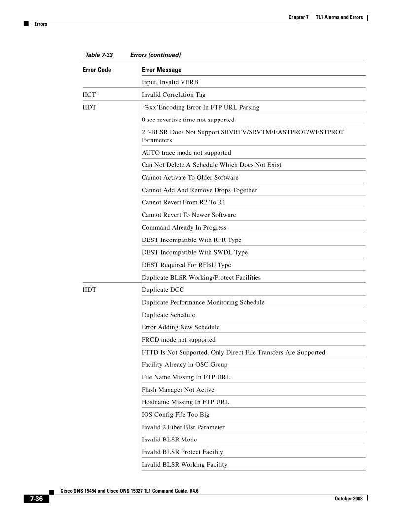
Input, Invalid VERB
IICT Invalid Correlation Tag
IIDT ‘%xx’Encoding Error In FTP URL Parsing
0 sec revertive time not supported
2F-BLSR Does Not Support SRVRTV/SRVTM/EASTPROT/WESTPROT Parameters
AUTO trace mode not supported
Can Not Delete A Schedule Which Does Not Exist
Cannot Activate To Older Software
Cannot Add And Remove Drops Together
Cannot Revert From R2 To R1
Cannot Revert To Newer Software
Command Already In Progress
DEST Incompatible With RFR Type
DEST Incompatible With SWDL Type
DEST Required For RFBU Type
Duplicate BLSR Working/Protect Facilities
IIDT Duplicate DCC
Duplicate Performance Monitoring Schedule
Duplicate Schedule
Error Adding New Schedule
FRCD mode not supported
FTTD Is Not Supported. Only Direct File Transfers Are Supported
Facility Already in OSC Group
File Name Missing In FTP URL
Flash Manager Not Active
Hostname Missing In FTP URL
IOS Config File Too Big
Invalid 2 Fiber Blsr Parameter
Invalid BLSR Mode
Invalid BLSR Protect Facility
Invalid BLSR Working Facility
Table 7-33 Errors (continued)
Error Code Error Message
7-36Cisco ONS 15454 and Cisco ONS 15327 TL1 Command Guide, R4.6
October 2008
Chapter 7 TL1 Alarms and ErrorsErrors
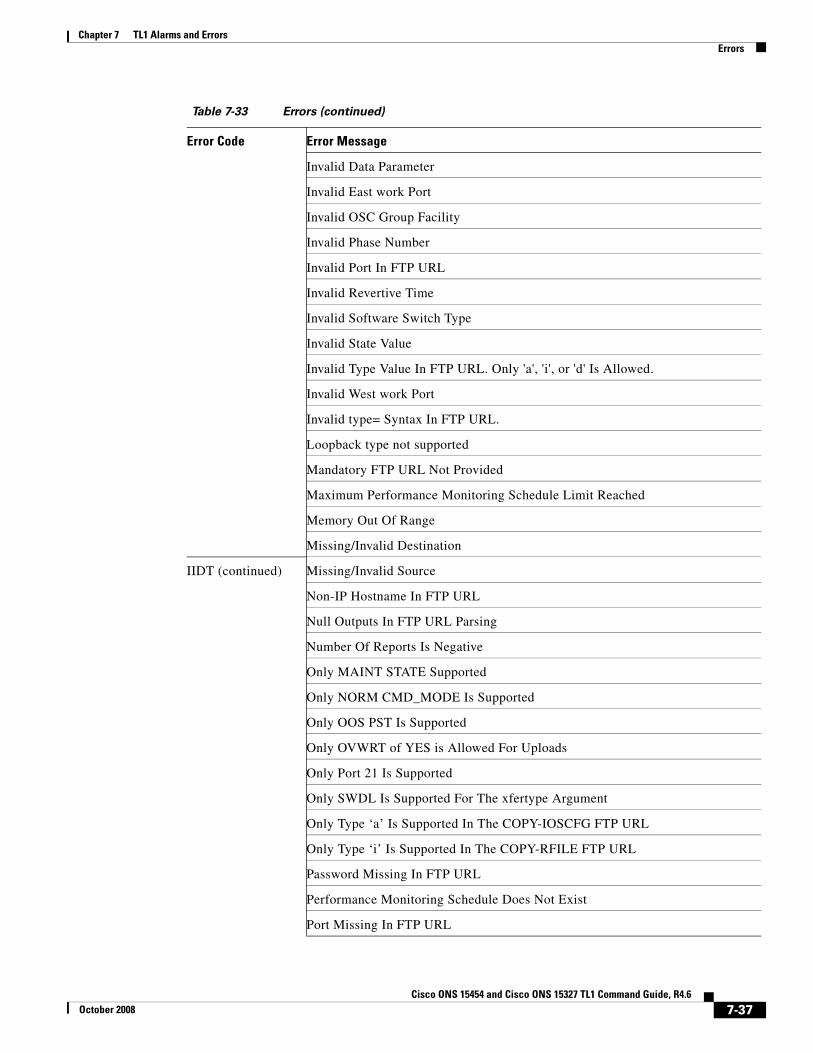
Invalid Data Parameter
Invalid East work Port
Invalid OSC Group Facility
Invalid Phase Number
Invalid Port In FTP URL
Invalid Revertive Time
Invalid Software Switch Type
Invalid State Value
Invalid Type Value In FTP URL. Only 'a', 'i', or 'd' Is Allowed.
Invalid West work Port
Invalid type= Syntax In FTP URL.
Loopback type not supported
Mandatory FTP URL Not Provided
Maximum Performance Monitoring Schedule Limit Reached
Memory Out Of Range
Missing/Invalid Destination
IIDT (continued) Missing/Invalid Source
Non-IP Hostname In FTP URL
Null Outputs In FTP URL Parsing
Number Of Reports Is Negative
Only MAINT STATE Supported
Only NORM CMD_MODE Is Supported
Only OOS PST Is Supported
Only OVWRT of YES is Allowed For Uploads
Only Port 21 Is Supported
Only SWDL Is Supported For The xfertype Argument
Only Type ‘a’ Is Supported In The COPY-IOSCFG FTP URL
Only Type ‘i’ Is Supported In The COPY-RFILE FTP URL
Password Missing In FTP URL
Performance Monitoring Schedule Does Not Exist
Port Missing In FTP URL
Table 7-33 Errors (continued)
Error Code Error Message
7-37Cisco ONS 15454 and Cisco ONS 15327 TL1 Command Guide, R4.6
October 2008
Chapter 7 TL1 Alarms and ErrorsErrors
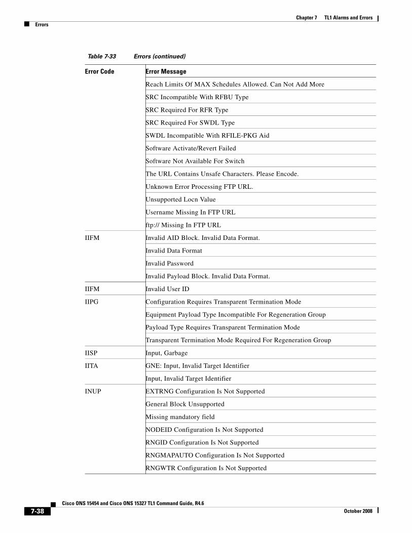
Reach Limits Of MAX Schedules Allowed. Can Not Add More
SRC Incompatible With RFBU Type
SRC Required For RFR Type
SRC Required For SWDL Type
SWDL Incompatible With RFILE-PKG Aid
Software Activate/Revert Failed
Software Not Available For Switch
The URL Contains Unsafe Characters. Please Encode.
Unknown Error Processing FTP URL.
Unsupported Locn Value
Username Missing In FTP URL
ftp:// Missing In FTP URL
IIFM Invalid AID Block. Invalid Data Format.
Invalid Data Format
Invalid Password
Invalid Payload Block. Invalid Data Format.
IIFM Invalid User ID
IIPG Configuration Requires Transparent Termination Mode
Equipment Payload Type Incompatible For Regeneration Group
Payload Type Requires Transparent Termination Mode
Transparent Termination Mode Required For Regeneration Group
IISP Input, Garbage
IITA GNE: Input, Invalid Target Identifier
Input, Invalid Target Identifier
INUP EXTRNG Configuration Is Not Supported
General Block Unsupported
Missing mandatory field
NODEID Configuration Is Not Supported
RNGID Configuration Is Not Supported
RNGMAPAUTO Configuration Is Not Supported
RNGWTR Configuration Is Not Supported
Table 7-33 Errors (continued)
Error Code Error Message
7-38Cisco ONS 15454 and Cisco ONS 15327 TL1 Command Guide, R4.6
October 2008

Chapter 7 TL1 Alarms and ErrorsErrors
IPEX Duplicate N/V field
Invalid Payload Block. Extra Parameters.
Invalid Payload Block. Extra Parameters.
IPMS Invalid AID Block. Missing Mandatory Field.
Invalid Payload Block. Missing Mandatory Field.
Invalid syntax
Missing mandatory field
IPNC Cannot Change Existing Protection Type
Cross-connect Doesn't Have UPSR Path Selector
Description Cannot Have More Than 64 Characters
Invalid Flow Control Value
Invalid Maximum Frame Size
Invalid Parameter
Invalid Trans Value
Parameter Not Valid
Parameters Are Not Consistent
IPNV Parameters Not Compatible
AID or Condition Must Be Specified
Bad IP Configuration Parameter
Bad Parameter
Bad Reference
Cannot Set Expected Path Trace For Source Path
Cannot Set Expected Path Trace In Auto Mode
Cannot Set Outgoing Path Trace For Drop Path
Cross-Connection Does Not Have UPSR Path Selector
Empty parameter
Exercise Is Not Allowed On Protected Facility
Expected Trace String Exceeds Max Length (62)
Facility Does Not Support Montype
Far End Loopback Type Not Supported In Current Framing Format
Far End Performance Monitoring Values Not Supported
Table 7-33 Errors (continued)
Error Code Error Message
7-39Cisco ONS 15454 and Cisco ONS 15327 TL1 Command Guide, R4.6
October 2008

Chapter 7 TL1 Alarms and ErrorsErrors
Holdoff Timer Not Supported For Non-DRI Cross-Connections
INT Not Valid For BITS-OUT
Internal-Ip Lookup Failed
Internal-Network Nodes Lookup Failed
Invalid Clock Source
Invalid Condition Type
Invalid Default Router Address
Invalid IIOP Port number
Invalid IP Address
Invalid IP Configuration Parameter
Invalid IP Mask
Invalid MONLEV Value
Invalid PM register
Invalid Parameter
Invalid Payload Block. Empty Parameter.
Invalid Report Interval
IPNV (continued) Invalid SNTP Host Address
Invalid Start Time
Invalid Switch Command For Synchronization
Invalid Switch Type
Invalid Threshold Value
Invalid why parameter
New Source Must Be Specified
Node Name Exceeds Maximum Length
Number Of Reports Is Negative
PM Not Supported
Parameter Not Valid
Payload Does Not Support Optics Montypes
Primary Reference Incompatible With Timing Mode
Protection Type Does Not Support Reversion Mode
Reference Type Not Supported
Table 7-33 Errors (continued)
Error Code Error Message
7-40Cisco ONS 15454 and Cisco ONS 15327 TL1 Command Guide, R4.6
October 2008

Chapter 7 TL1 Alarms and ErrorsErrors
SPNWTR Parameter Not Supported
Secondary Reference Incompatible With Timing Mode
Synchronization Source Already Defined For The Slot
TMGREF Parameter Not Supported
Third Reference Incompatible With Timing Mode
Time Period Not Applicable
Timing Mode Not Compatible
PICC AID Required
AID does not match this session UID
Bad Password Toggling - New Password Same As A Prior Password
Can't change own security level
Can't login
Can't logout if user not logged in
Command Not Available To This User Level
Command Not Available to this User Level
Invalid User Access Privilege Value
PICC (continued) Invalid User Identifier - Must Conform To TL1 Rules
Invalid User Password - Must Conform To TL1 Rules
Logout failed
Password Must Be Changed Before Continuing
Password Recently Changed.
Unexpected Default Case
Unknown CORBA Exception (Internal Error)
Unknown User
User Access Privilege Required
User Already Exists
User Identifier Exceeds Maximum Length Allowed
User Not Authorized
User Password Required
PIMA Memory Out Of Range
PIUC Cannot Delete The Logged In User
Table 7-33 Errors (continued)
Error Code Error Message
7-41Cisco ONS 15454 and Cisco ONS 15327 TL1 Command Guide, R4.6
October 2008

Chapter 7 TL1 Alarms and ErrorsErrors
Cannot Remove The Last Superuser
Unauthorized change of PID
Unauthorized
User Currently Logged Into Another Session
User Is Not Superuser
User Not Allowed To Change User Access Privilege
User Not Allowed To Change User Password
User Not Allowed To Disable/Enable Self
User Not Allowed To Terminate Self
User Not Logged In
RALB GNE: All ENE Connections in Use
Requested DCC In Use
RANB GNE: No Response from ENE - IENE
RNBY Software upgrade in progress
RRNG I/O Slot Out Of Range
Invalid Slot Number
RTBY Connection In Service
TAP Already In Use
TAP Number In Use
RTEN Cannot Access VT
Cannot Change Access Mode
Cannot Set Access Mode
Invalid Access Mode
Invalid STS TAP Number
Invalid TAP AID
Invalid TAP Mode
Invalid TAP Number
Invalid VT TAP Number
Requested TAP Does Not Exist
Requested Tap Busy
TAP Not Found
Table 7-33 Errors (continued)
Error Code Error Message
7-42Cisco ONS 15454 and Cisco ONS 15327 TL1 Command Guide, R4.6
October 2008

Chapter 7 TL1 Alarms and ErrorsErrors
SAAL Already Allowed
SAAS Equipment Already Provisioned
SADC GNE: ENE is down
TAP Not Connected
SADS Loopback Applied On Cross-connection
SAIN Already Inhibited
SAIS Port Already In Service
SAMS Already In Clear Maintenance State
Already In Force Maintenance State
Already In Lockout Maintenance State
Already In Manual Maintenance State
SAOP Control Already Operated
Control Already Released
Control Operated In Mntry
SAOS Port Already In OOS-AINS
Port Already In OOS-MT
SAOS (continued) Port Already Out Of Service
SAPR Cannot Provision Regeneration Group When A Protection Group Is Present
SARB GNE: All Gateways in Use
System Memory Exhausted. Retry A Few Seconds Later
SCAT Connection already in loopback
Connection already in roll
Connection already in test access
Connection is tapped
End Point Is Already Connected
STS Is Already Connected
Test Access Busy
VT Is Already Connected
Would exceed max number of drops
SDBE AID Parser Failed
Asymmetric VCG Not Supported
Table 7-33 Errors (continued)
Error Code Error Message
7-43Cisco ONS 15454 and Cisco ONS 15327 TL1 Command Guide, R4.6
October 2008
Chapter 7 TL1 Alarms and ErrorsErrors
Bad Parameter
Cannot Access Alarms
Cannot Access Conditions
Cannot Access Controls
Cannot Access Date/Time
Cannot Access Defaults Description
Cannot Access Environmental Settings
Cannot Access Equipment
Cannot Access Facility
Cannot Access IP Configuration
Cannot Access Interface
Cannot Access Node ID
Cannot Access Node Name
Cannot Access Object
Cannot Access Orderwire
Cannot Access Protection Group
SDBE (continued) Cannot Access Protection State
Cannot Access SNMP Ip Addr
Cannot Access SNTP Host
Cannot Access STS
Cannot Access Software Version
Cannot Access Synchronization Configuration
Cannot Access Timezone
Cannot Access Trace Information
Cannot Access VT Performance Monitoring Parameters
Cannot Access VT
Cannot Configure SYNC
Cannot Create 1+1 Protection Group
Cannot Edit STS
Cannot Get Line Information
Cannot Get Synchronization Configuration
Table 7-33 Errors (continued)
Error Code Error Message
7-44Cisco ONS 15454 and Cisco ONS 15327 TL1 Command Guide, R4.6
October 2008

Chapter 7 TL1 Alarms and ErrorsErrors
Cannot Set Date When Using SNTP
Cannot Set Date
Cannot Set IP Configuration
Cannot Set Node Name
Cannot Set Pointer Justification Monitoring Parameter (PJMON)
Cannot Set SNTP Host Configuration
Cannot Set Timezone
Cannot Soft Reset System
Cannot Switch To E2 Byte With Express Orderwire IS
Card Type Not Supported
DLT prg Failed
Delete Protection Group Failed
Equipment Not Found
Facility Does Not Exist
Facility Does Not Match Request
Facility Does Not Support Mac Address
SDBE (continued) Facility Is Not Provisioned
Facility Not Provisioned
File Transfer In Progress
Get Sonet Line Info Failed
Getting sonet sync configurations
IOS Config Update In Progress
IP Configuration Failed
Incompatible Parameter Values
Incorrect Facility Type
Interface Does Not Exist
Interface Does Not Support Loopback Type
Internal Access Failed
Internal Data Base Error
Internal Database Error
Invalid Command
Table 7-33 Errors (continued)
Error Code Error Message
7-45Cisco ONS 15454 and Cisco ONS 15327 TL1 Command Guide, R4.6
October 2008
Chapter 7 TL1 Alarms and ErrorsErrors
Invalid Cross Connect Type For VCG
Invalid DCC
Invalid Mondat Format
Invalid Montm Format
Invalid Performance Monitoring Mode
Invalid Protection Group
Invalid Time Period
Invalid Trace Mode for Card Type
LCAS Not Supported By This Card
Location Value Invalid
Loopback Is Invalid
Loopback Port In Service
Loopback type not supported
Mac Address Not Supported By Payload
No such interface
Node Name Configuration Failed
SDBE (continued) Not a Sonet interface
Object Not Provisioned
Object Not Supported
Operation Not Supported On EC1 Interface
Operation not supported by this card
Path Width Not Supported
Path loopback already exists
SNTP Configuration Failed
STS Not Provisioned
Synchronization Configuration Not Available
Synchronization Status Messaging(SSM) Not Supported On EC1 Interface
Synchronization::Sync not available
Used Frame Format Does Not Support Synchronization Status Messaging(SSM)
VT Not Provisioned
Wrong Facility Type
Table 7-33 Errors (continued)
Error Code Error Message
7-46Cisco ONS 15454 and Cisco ONS 15327 TL1 Command Guide, R4.6
October 2008

Chapter 7 TL1 Alarms and ErrorsErrors
Wrong Interface Type
bind failed for sonet gen
getActiveRefSource failed
getRefSources failed
SDLD Duplex Unit Locked
SDNA Active TCC Not Ready
Standby TCC Not Ready
SNCC Cross connection does not exist
Path roll does not exist
Replace This Message When A SNCC message is needed
SNCN Bad Quality
Cannot Switch To Inferior Reference Source
Clock Source Failed
Command Not Implemented
Cross-Connection Type Not Supported In TL1
Invalid Clock Source
SNCN (continued) Requested Direction Not Supported
STS Rate Changing Not Supported
SNNS Reference Not From Optical Card
SNOS Cannot Change Card Wavelength With Port(s) Not In OOS State
Cannot Change Payload With Port(s) Not In OOS State
Cannot Change Termination Mode With Port(s) Not In OOS State
SNPR Cannot Get Role Of Port
Get Port Role Failed
SNVS Already Switched To Internal Reference Source
BLSR East Operation Already Set
BLSR West Operation Already Set
CCAT Cross Connect Exists
Cannot Change Configuration When Port(s) Are Not In OOS State
Cannot Change Payload For Protection Group
Cannot Change Payload When Port(s) Are DCC Enabled
Table 7-33 Errors (continued)
Error Code Error Message
7-47Cisco ONS 15454 and Cisco ONS 15327 TL1 Command Guide, R4.6
October 2008

Chapter 7 TL1 Alarms and ErrorsErrors
Cannot Change Payload When Port(s) Are Used As A Clock Source
Cannot Change Termination Mode When Port(s) Are DCC Enabled
Cannot Change Termination Mode When Port(s) Are Used As a Clock Source
Cannot Change Termination Mode With Trace Enabled
Cannot END an AUTO roll
Cannot Edit Facility When Not In OOS State
Cannot Operate Loopback In Current Cross-connection State
Cannot Operate Loopback In Current State
Cannot Provision Regeneration Group When A Protection Switch Operation Is Present
Cannot Provision Regeneration Group When Equipment Has Different FEC Settings
Cannot Provision Regeneration Group When Equipment Has Different G.709 Settings
Cross Connect Exists
Facility Not Part Of BLSR
Invalid AINS Soak Time
SNVS (continued) Invalid Admin State
Invalid BLSR Element
Invalid Clock Source
Invalid Equipment State
Invalid Transponder Provisioning
Loopback Already In Progress
Loopback Not In Progress
No Switch In Progress
No valid roll signal
Protection Group Does Not Exist
Protection Unit Active
Roll condition does not exist
Roll is not controlled by TL1
Status, Not in Valid State
Unable to complete roll
Table 7-33 Errors (continued)
Error Code Error Message
7-48Cisco ONS 15454 and Cisco ONS 15327 TL1 Command Guide, R4.6
October 2008
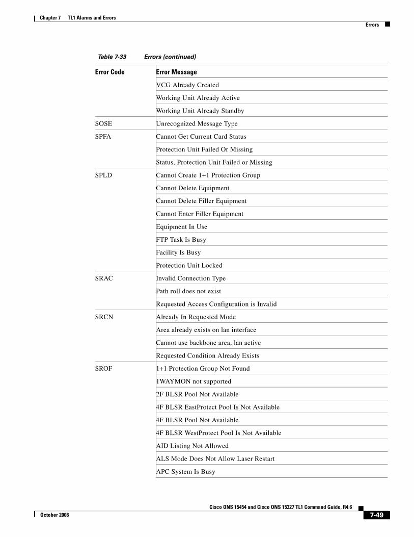
Chapter 7 TL1 Alarms and ErrorsErrors
VCG Already Created
Working Unit Already Active
Working Unit Already Standby
SOSE Unrecognized Message Type
SPFA Cannot Get Current Card Status
Protection Unit Failed Or Missing
Status, Protection Unit Failed or Missing
SPLD Cannot Create 1+1 Protection Group
Cannot Delete Equipment
Cannot Delete Filler Equipment
Cannot Enter Filler Equipment
Equipment In Use
FTP Task Is Busy
Facility Is Busy
Protection Unit Locked
SRAC Invalid Connection Type
Path roll does not exist
Requested Access Configuration is Invalid
SRCN Already In Requested Mode
Area already exists on lan interface
Cannot use backbone area, lan active
Requested Condition Already Exists
SROF 1+1 Protection Group Not Found
1WAYMON not supported
2F BLSR Pool Not Available
4F BLSR EastProtect Pool Is Not Available
4F BLSR Pool Not Available
4F BLSR WestProtect Pool Is Not Available
AID Listing Not Allowed
ALS Mode Does Not Allow Laser Restart
APC System Is Busy
Table 7-33 Errors (continued)
Error Code Error Message
7-49Cisco ONS 15454 and Cisco ONS 15327 TL1 Command Guide, R4.6
October 2008
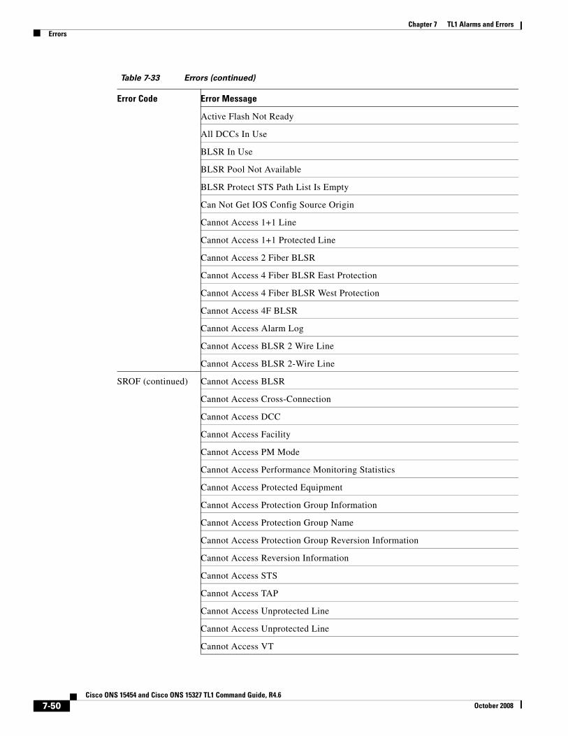
Chapter 7 TL1 Alarms and ErrorsErrors
Active Flash Not Ready
All DCCs In Use
BLSR In Use
BLSR Pool Not Available
BLSR Protect STS Path List Is Empty
Can Not Get IOS Config Source Origin
Cannot Access 1+1 Line
Cannot Access 1+1 Protected Line
Cannot Access 2 Fiber BLSR
Cannot Access 4 Fiber BLSR East Protection
Cannot Access 4 Fiber BLSR West Protection
Cannot Access 4F BLSR
Cannot Access Alarm Log
Cannot Access BLSR 2 Wire Line
Cannot Access BLSR 2-Wire Line
SROF (continued) Cannot Access BLSR
Cannot Access Cross-Connection
Cannot Access DCC
Cannot Access Facility
Cannot Access PM Mode
Cannot Access Performance Monitoring Statistics
Cannot Access Protected Equipment
Cannot Access Protection Group Information
Cannot Access Protection Group Name
Cannot Access Protection Group Reversion Information
Cannot Access Reversion Information
Cannot Access STS
Cannot Access TAP
Cannot Access Unprotected Line
Cannot Access Unprotected Line
Cannot Access VT
Table 7-33 Errors (continued)
Error Code Error Message
7-50Cisco ONS 15454 and Cisco ONS 15327 TL1 Command Guide, R4.6
October 2008

Chapter 7 TL1 Alarms and ErrorsErrors
Cannot Add Equipment
Cannot Add Equipment
Cannot Change BITS Configuration When Manual Switch Exists
Cannot Change Ethernet IP With DHCP Provisioned
Cannot Change Ethernet IP With OSPF Provisioned
Cannot Change Parameter When Manual Switch Exists
Cannot Change Port State When Manual Switch Exists
Cannot Change Synchronization Configuration When Manual Switch Exists
Cannot Change Timing Reference When Manual Switch Exists
Cannot Change XTC Protection Group
Cannot Configure SYNC
Cannot Create Cross-Connection Between Incompatible Interfaces
Cannot Create Protection Group
Cannot Create Protection Group with Pre-provisioned Cards when CMDMDE is FRCD
Cannot Create TAP On Last VT
SROF (continued) Cannot Create TAP
Cannot Create Y cable Protection
Cannot Delete Cross-Connection
Cannot Delete Last Drop
Cannot Delete Protected Equipment
Cannot Delete Protection Group
Cannot Delete Protection Group with Cross-Connections on Working Card when CMDMDE is FRCD
Cannot Disable DWRAP With FEC Enabled
Cannot Disable DWRAP With GCC Enabled
Cannot Disable DWRAP. Orderwire Circuit Exists
Cannot Disable DWRAP. Y-Cable Protection Exists
Cannot Edit Ethernet IP
Cannot Edit STS
Cannot Enable FEC When G.709 Is Disabled
Cannot Enable FEC With DWRAP Disabled
Table 7-33 Errors (continued)
Error Code Error Message
7-51Cisco ONS 15454 and Cisco ONS 15327 TL1 Command Guide, R4.6
October 2008

Chapter 7 TL1 Alarms and ErrorsErrors
Cannot Modify Protect Card
Cannot Perform ACO
Cannot Provision Equipment
Cannot Provision Protection Equipment
Cannot Set ALS Mode
Cannot Set Bidirectional Protection Group
Cannot Set DCC When Digital Wrapper Is Enabled
Cannot Set GCC When DWRAP Is Disabled
Cannot Set NodeId
Cannot Set Payload Type
Cannot Set Protection Group Name
Cannot Set Protection Group Revertive Behavior
Cannot Set RingId
Cannot Set Span Revertive Mode Unless 4-Fiber Ring
Cannot Set Span Revertive Time In Non-revertive Mode
Cannot Set Span Revertive Time Unless 4-Fiber Ring
SROF (continued) Cannot Set Termination Mode
Cannot Set Wave Length
Cannot Switch For Specified Connection Type
Cannot Switch For Specified Path
Cannot Update Synchronization Reference List
Cannot modify cross connect right now
Cannot roll a non-TL1 circuit
Cannot set loopback
Command Not Supported
Connection is already in roll
Connection type error
Connection type error
Could Not Delete Protection
Could not provision area
Cross-Connection Creation Failed
Table 7-33 Errors (continued)
Error Code Error Message
7-52Cisco ONS 15454 and Cisco ONS 15327 TL1 Command Guide, R4.6
October 2008
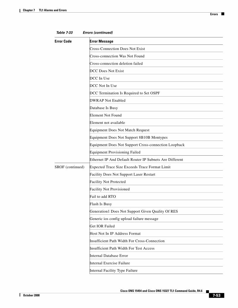
Chapter 7 TL1 Alarms and ErrorsErrors
Cross-Connection Does Not Exist
Cross-connection Was Not Found
Cross-connection deletion failed
DCC Does Not Exist
DCC In Use
DCC Not In Use
DCC Termination Is Required to Set OSPF
DWRAP Not Enabled
Database Is Busy
Element Not Found
Element not available
Equipment Does Not Match Request
Equipment Does Not Support 8B10B Montypes
Equipment Does Not Support Cross-connection Loopback
Equipment Provisioning Failed
Ethernet IP And Default Router IP Subnets Are Different
SROF (continued) Expected Trace Size Exceeds Trace Format Limit
Facility Does Not Support Laser Restart
Facility Not Protected
Facility Not Provisioned
Fail to add RTO
Flash Is Busy
Generation1 Does Not Support Given Quality Of RES
Generic ios config upload failure message
Get IOR Failed
Host Not In IP Address Format
Insufficient Path Width For Cross-Connection
Insufficient Path Width For Test Access
Internal Database Error
Internal Exercise Failure
Internal Facility Type Failure
Table 7-33 Errors (continued)
Error Code Error Message
7-53Cisco ONS 15454 and Cisco ONS 15327 TL1 Command Guide, R4.6
October 2008

Chapter 7 TL1 Alarms and ErrorsErrors
Invalid AID
Invalid ALS Recovery Interval
Invalid ALS Recovery Pulse Width
Invalid Control Type (CONTTYPE) For AID
Invalid Cross Connect Type For VCG
Invalid Cross-Connection Path
Invalid Cross-Connection Type For Drops
Invalid Drop Path
Invalid FTP Username/Password
Invalid Loopback Provision
Invalid Operation For Connection Type
Invalid Operation For Specified Path
Invalid Path
Invalid Protection Group
Invalid Protection Switch Operation
Invalid RMODE
SROF (continued) Invalid SYNC entity
Invalid State When Loopback Present
Invalid Subnet Mask
Invalid Synchronization Source
Invalid UPSR Path
Invalid type for this Cross connection
Is Not 1+1 Element Type
J0 Section Trace Level Not Supported By 10GE Payload Type
Laser Was Not Shutdown.Cannot Restart Laser
Location Incompatible With Loopback Type
Loopback Not Allowed On Drop Path
Loopback Type Does Not Match
MIC Cards Cannot Be Reset
Maximum Drop Limit Reached
Maximum User Limit Reached
Table 7-33 Errors (continued)
Error Code Error Message
7-54Cisco ONS 15454 and Cisco ONS 15327 TL1 Command Guide, R4.6
October 2008

Chapter 7 TL1 Alarms and ErrorsErrors
Maximum VT Cross Connection Limit Reached
No Path To Regulate
No Start-Up IOS Config
No clock and data copy information from Line cards and CXC cards
Node::General not available
Node::NetworkConfig not available
Non Revertive Mode Does Not Allow to Set RVTM
Not Enough Path Width For TACC
Number of Drops Exceed Allowable
One Plus One Line pool not available
Operate Alarm Cutoff Failed
Operation Not Supported
Operation not Valid for Connection Type
Operation not Valid for Path Specified
OspfTopology::OSPFTopo not available
Parameter Not Supported When DWRAP Is Enabled
SROF (continued) Path Already In Use
Path Specified Is Not Valid
Path Used For Test Access
Payload Type Does Not Support Trace
Peer Equipment Attributes Do Not Match
Peer Equipment Type Does Not Match
Peer Facility Has Loopback
Peer Facility In Use
Peer Payload Type Does Not Match
Peer Termination Mode Does Not Match
Pool Does Not Exist
Pool not available
Protect Port Active
Protection Group Does Not Exist
Protection Switching Failed
Table 7-33 Errors (continued)
Error Code Error Message
7-55Cisco ONS 15454 and Cisco ONS 15327 TL1 Command Guide, R4.6
October 2008
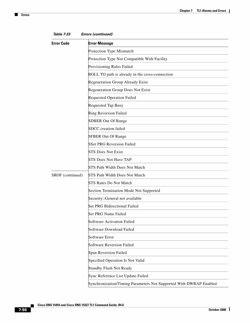
Chapter 7 TL1 Alarms and ErrorsErrors
Protection Type Mismatch
Protection Type Not Compatible With Facility
Provisioning Rules Failed
ROLL TO path is already in the cross-connection
Regeneration Group Already Exist
Regeneration Group Does Not Exist
Requested Operation Failed
Requested Tap Busy
Ring Reversion Failed
SDBER Out Of Range
SDCC creation failed
SFBER Out Of Range
SSet PRG Reversion Failed
STS Does Not Exist
STS Does Not Have TAP
STS Path Width Does Not Match
SROF (continued) STS Path Width Does Not Match
STS Rates Do Not Match
Section Termination Mode Not Supported
Security::General not available
Set PRG Bidirectional Failed
Set PRG Name Failed
Software Activation Failed
Software Download Failed
Software Error
Software Reversion Failed
Span Reversion Failed
Specified Operation Is Not Valid
Standby Flash Not Ready
Sync Reference List Update Failed
Synchronization/Timing Parameters Not Supported With DWRAP Enabled
Table 7-33 Errors (continued)
Error Code Error Message
7-56Cisco ONS 15454 and Cisco ONS 15327 TL1 Command Guide, R4.6
October 2008

Chapter 7 TL1 Alarms and ErrorsErrors
TAP connected
TTI Trace Not Allowed With G709 Disabled
Tap Not Provisioned
Test Access Active
Test Access Not Supported On Card
Trace Format Not Supported By J0 Section Trace
Trace Format Not Supported By TTI Section Trace
Trace Message Size Exceeds Trace Format Limit
Trace Mode Incompatible With Termination Mode
Trace Mode Not Supported
UPSR Needed To Change Revertive Behavior
Unable to cancel roll
Unknown Internal Error
Unprotected Line pool not available
Unprovisioning Rules Failed
Unsupported BLSR STS Path Operation
SROF (continued) Unsupported Command Type
Unsupported Element Type
VCG Does Not Exist
VT Cross-Connection Does Not Exist
VT Does Not Exist
VT Does Not Have TAP
VT Path Width Does Not Match
Wavelength Value Not Supported
Working/Peer Card In Use
Wrong Interface Type
XC Card Does Not Support VT Cross-Connection
XC Card Not Present
XCVXL Card Not Present
Y-Cable Protection Does Not Exist
SRQN BLSR Creation Failed
Table 7-33 Errors (continued)
Error Code Error Message
7-57Cisco ONS 15454 and Cisco ONS 15327 TL1 Command Guide, R4.6
October 2008

Chapter 7 TL1 Alarms and ErrorsErrors
BLSR Deletion Failed
BLSR Does Not Exist
BLSR Editing Failed
Cannot Create Automatic Links
Cannot Edit SENDDUS On Protect Port
Cannot Edit SYNCMSG On Protect Port
DCC Not Allowed On Protect Port
DCC not enabled
Data Access Request Failed
Invalid Mode For Current Configuration
Invalid Request
OSC Group Already Exists
OSC Group Does Not Exist
Path loopback already exists
Protect Card Does Not Support Electrical Protection
Protect Card Does Not Support Protection Type
SRQN (continued) STS Cross-Connection Does Not Exist
VT Cross-Connection Does Not Exist
SRTN TAP Not Found
SSRD Manual Switch Cannot Override Forced Switch
Switch Request Denied
SSRE GNE: ENE Connection Closed
GNE: System Resources Exceeded - FD
GNE: System Resources Exceeded - Lock
GNE: System Resources Exceeded - Thread
Memory Resources Exceeded
Memory resource denial
SWFA Status, Working Unit Failed or Missing
Working Unit Failed Or Missing
SWLD Working Unit Locked
Table 7-33 Errors (continued)
Error Code Error Message
7-58Cisco ONS 15454 and Cisco ONS 15327 TL1 Command Guide, R4.6
October 2008

Chapter 7 TL1 Alarms and ErrorsEcho
7.4 EchoIn order to improve telnet functionality for automated systems, the echo function has been turned off since ONS 15454 Release 3.0. This change is transparent to users running standard UNIX-compliant telnet clients; however, PC users may need to change their client setup to enable “local echo.” This is normally accomplished by a pull-down menu or a preference attribute.
To test the local echo on your PC client, use the RTRV-HDR command. If you receive a response but no data, set local echo ON. Cisco recommends that you close any windows containing sensitive information after exiting a TL1 session.
7-59Cisco ONS 15454 and Cisco ONS 15327 TL1 Command Guide, R4.6
October 2008

Chapter 7 TL1 Alarms and ErrorsEcho
7-60Cisco ONS 15454 and Cisco ONS 15327 TL1 Command Guide, R4.6
October 2008