Titolo - ABB Ltd L5975 Ekip Display User and operator manual for display for protection releases...
54
1SDH000892R0002 L5975 Ekip Display User and operator manual for display for protection releases Tmax XT series Power and productivity for a better world TM ABB Ekip Display User and operator manual
Transcript of Titolo - ABB Ltd L5975 Ekip Display User and operator manual for display for protection releases...
1SDH000892R0002 L5975
Ekip Display
User and operator manual for display for protection releases Tmax XT series
Power and productivity for a better worldTM ABB
Ekip Display
User and operator manual
L5048 Version L5975
Apparatus Ekip Display
Language
EN
ABBDoc. No 1SDH000892R0002
Pag. No
2/54
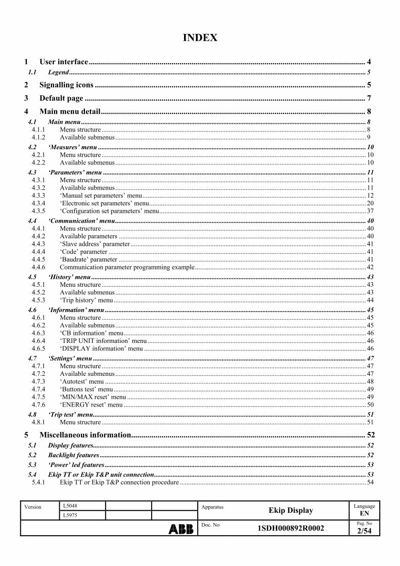
INDEX
1 User interface......................................................................................................................................... 4 1.1 Legend ............................................................................................................................................................................... 5
2 Signalling icons ...................................................................................................................................... 5
3 Default page ........................................................................................................................................... 7
4 Main menu detail................................................................................................................................... 8 4.1 Main menu ........................................................................................................................................................................ 8
4.1.1 Menu structure ............................................................................................................................................................ 8 4.1.2 Available submenus.................................................................................................................................................... 9
4.2 ‘Measures’ menu .............................................................................................................................................................. 10 4.2.1 Menu structure ............................................................................................................................................................ 10 4.2.2 Available submenus.................................................................................................................................................... 10
4.3 ‘Parameters’ menu ........................................................................................................................................................... 11 4.3.1 Menu structure ............................................................................................................................................................ 11 4.3.2 Available submenus.................................................................................................................................................... 11 4.3.3 ‘Manual set parameters’ menu.................................................................................................................................... 12 4.3.4 ‘Electronic set parameters’ menu................................................................................................................................ 20 4.3.5 ‘Configuration set parameters’ menu.......................................................................................................................... 37
4.4 ‘Communication’ menu.................................................................................................................................................... 40 4.4.1 Menu structure ............................................................................................................................................................ 40 4.4.2 Available parameters .................................................................................................................................................. 40 4.4.3 ‘Slave address’ parameter ........................................................................................................................................... 41 4.4.4 ‘Code’ parameter ........................................................................................................................................................ 41 4.4.5 ‘Baudrate’ parameter .................................................................................................................................................. 41 4.4.6 Communication parameter programming example..................................................................................................... 42
4.5 ‘History’ menu .................................................................................................................................................................. 43 4.5.1 Menu structure ............................................................................................................................................................ 43 4.5.2 Available submenus.................................................................................................................................................... 43 4.5.3 ‘Trip history’ menu..................................................................................................................................................... 44
4.6 ‘Information’ menu .......................................................................................................................................................... 45 4.6.1 Menu structure ............................................................................................................................................................ 45 4.6.2 Available submenus.................................................................................................................................................... 45 4.6.3 ‘CB information’ menu............................................................................................................................................... 46 4.6.4 ‘TRIP UNIT information’ menu................................................................................................................................. 46 4.6.5 ‘DISPLAY information’ menu ................................................................................................................................... 46
4.7 ‘Settings’ menu ................................................................................................................................................................. 47 4.7.1 Menu structure ............................................................................................................................................................ 47 4.7.2 Available submenus.................................................................................................................................................... 47 4.7.3 ‘Autotest’ menu .......................................................................................................................................................... 48 4.7.4 ‘Buttons test’ menu..................................................................................................................................................... 49 4.7.5 ‘MIN/MAX reset’ menu ............................................................................................................................................. 49 4.7.6 ‘ENERGY reset’ menu ............................................................................................................................................... 50
4.8 ‘Trip test’ menu................................................................................................................................................................. 51 4.8.1 Menu structure ............................................................................................................................................................ 51
5 Miscellaneous information.................................................................................................................... 52 5.1 Display features................................................................................................................................................................. 52 5.2 Backlight features ............................................................................................................................................................. 52 5.3 ‘Power’ led features .......................................................................................................................................................... 53 5.4 Ekip TT or Ekip T&P unit connection............................................................................................................................. 53
5.4.1 Ekip TT or Ekip T&P connection procedure .............................................................................................................. 54
L5048 Version L5975
Apparatus Ekip Display
Language
EN
ABBDoc. No 1SDH000892R0002
Pag. No
3/54
ABBREVIATIONS Tmax XT New series of moulded case breakers from ABB SACE CB Circuit Breaker TU Trip Unit TC Trip Coil PTC Rotor thermal protection Ekip LSI Protection relay for ABB SACE Tmax XT CB series Ekip LSIG Protection relay for ABB SACE Tmax XT CB series Ekip M-LRIU Protection relay for ABB SACE Tmax XT CB series Ekip E-LSIG Protection relay for ABB SACE Tmax XT CB series Ekip TT ABB SACE test unit Ekip T&P ABB SACE communication unit rms Root Mean Square value s/n Serial number SW Software
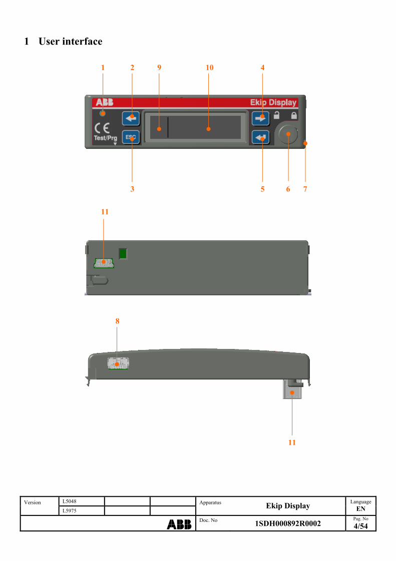
1 User interface
1 2 9 10
4
3 5 6 7
L5048 Version L5975
Apparatus Ekip Display
Language
EN
ABBDoc. No 1SDH000892R0002
Pag. No
4/54
11
8
11
1.1 Legend
Ref. Description Notes
1 ‘Power’ led 2 ‘Left’ cursor button 3 Exit or cancellation ‘Esc’ button 4 ‘Right’ cursor button 5 Confirm ‘Enter’ button 6 Mechanical fastening 7 Sealing slot 8 Ekip TT or Ekip T&P connector 9 Signalling icons display area See Par. 2: Signalling icons 10 Menu display area See Par. 4: main menu detail 11 TU connector
Tab. 1: user interface
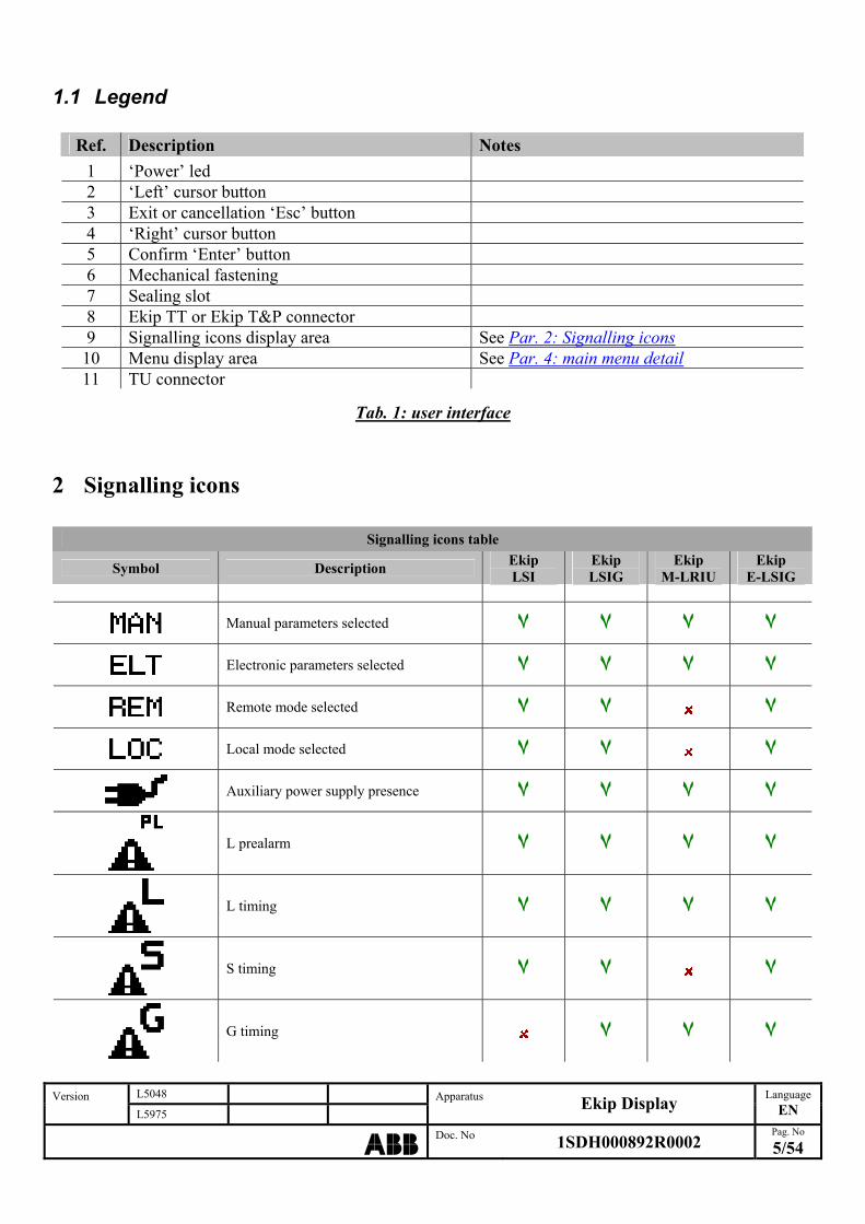
2 Signalling icons
Signalling icons table
Symbol Description Ekip LSI
Ekip LSIG
Ekip M-LRIU
Ekip E-LSIG
Manual parameters selected ٧ ٧ ٧ ٧
٧ ٧ ٧ Electronic parameters selected ٧
٧ ٧ Remote mode selected ٧
٧ ٧ Local mode selected ٧
٧ ٧ ٧ Auxiliary power supply presence ٧
L prealarm ٧ ٧ ٧ ٧
L timing ٧ ٧ ٧ ٧
S timing ٧ ٧ ٧
G timing ٧ ٧ ٧
L5048 Version L5975
Apparatus Ekip Display
Language
EN
ABBDoc. No 1SDH000892R0002
Pag. No
5/54
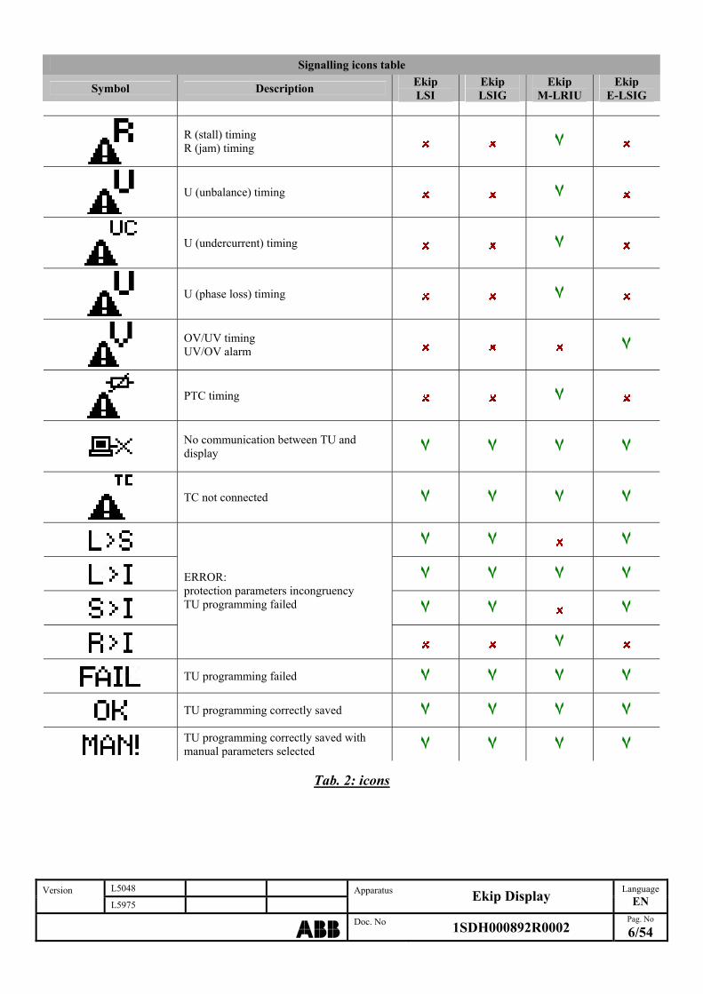
Signalling icons table
L5048 Version L5975
Apparatus Ekip Display
Language
EN
ABBDoc. No 1SDH000892R0002
Pag. No
6/54
Symbol Description Ekip LSI
Ekip LSIG
Ekip Ekip M-LRIU E-LSIG
R (stall) timing R (jam) timing ٧
U (unbalance) timing ٧
U (undercurrent) timing ٧
U (phase loss) timing ٧
OV/UV timing UV/OV alarm ٧
PTC timing ٧
No communication between TU and display ٧ ٧ ٧ ٧
TC not connected ٧ ٧ ٧ ٧
٧ ٧ ٧
٧ ٧ ٧ ٧
٧ ٧ ٧
ERROR: protection parameters incongruency TU programming failed
٧
TU programming failed ٧ ٧ ٧ ٧
٧ ٧ ٧ TU programming correctly saved ٧
TU programming correctly saved with manual parameters selected ٧ ٧ ٧ ٧
Tab. 2: icons
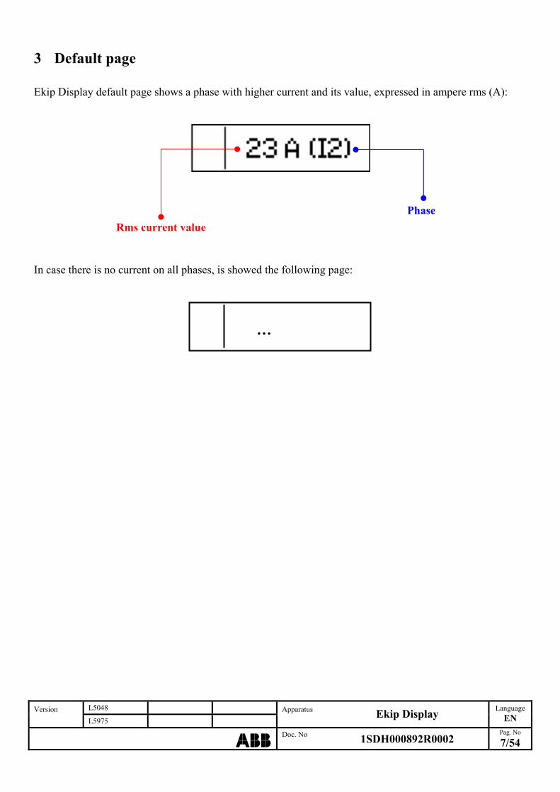
3 Default page Ekip Display default page shows a phase with higher current and its value, expressed in ampere rms (A):
Phase
Rms current value In case there is no current on all phases, is showed the following page:
…
L5048 Version L5975
Apparatus Ekip Display
Language
EN
ABBDoc. No 1SDH000892R0002
Pag. No
7/54
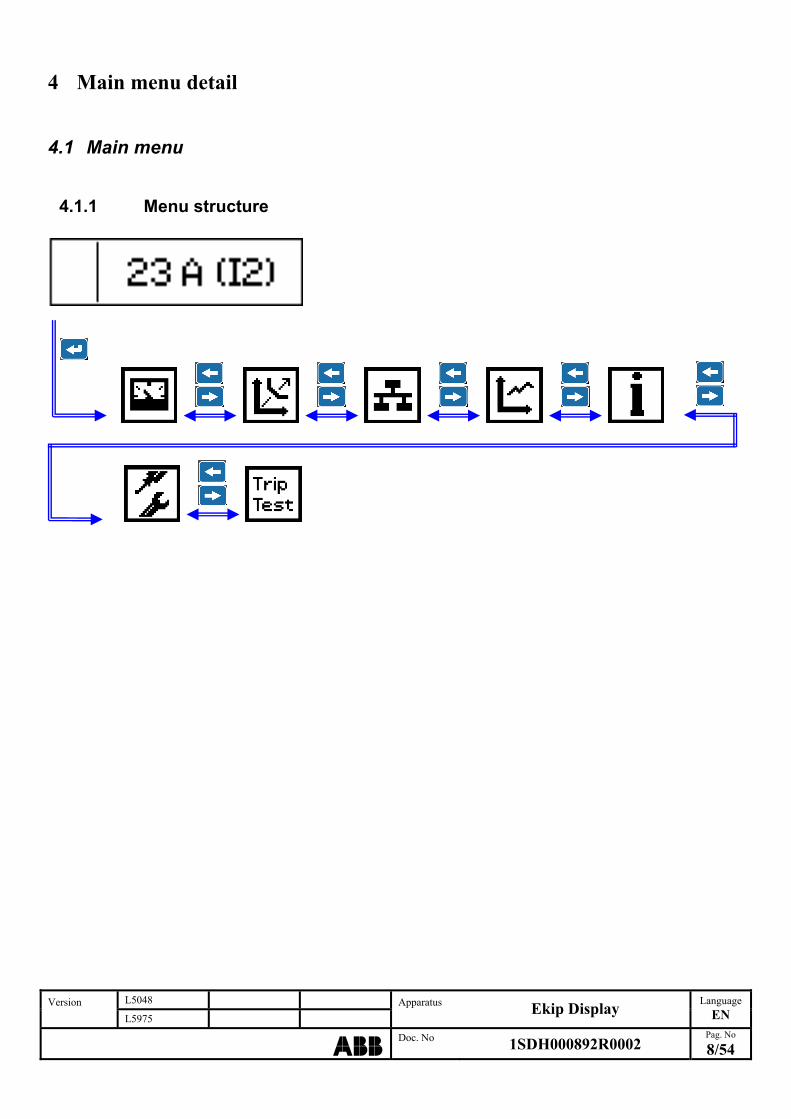
4 Main menu detail
4.1 Main menu
4.1.1 Menu structure
L5048 Version L5975
Apparatus Ekip Display
Language
EN
ABBDoc. No 1SDH000892R0002
Pag. No
8/54
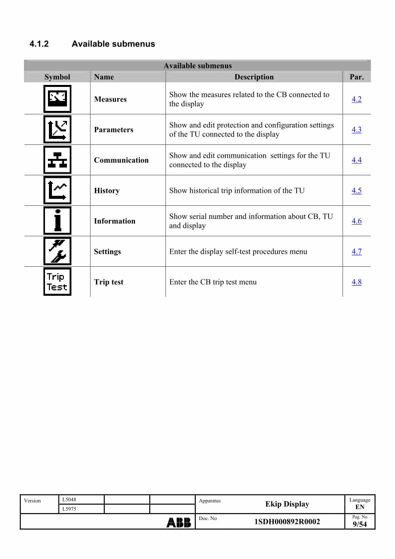
4.1.2 Available submenus
Available submenus
Symbol Name Description Par.
Measures Show the measures related to the CB connected to the display
4.2
Parameters Show and edit protection and configuration settings of the TU connected to the display
4.3
Communication Show and edit communication settings for the TU connected to the display
4.4
History Show historical trip information of the TU 4.5
Information Show serial number and information about CB, TU and display
4.6
Settings Enter the display self-test procedures menu 4.7
Trip test Enter the CB trip test menu 4.8
L5048 Version L5975
Apparatus Ekip Display
Language
EN
ABBDoc. No 1SDH000892R0002
Pag. No
9/54

4.2 ‘Measures’ menu Show the runtime current values of all phases.
4.2.1 Menu structure
L5048 Version L5975
Apparatus Ekip Display
Language
EN
ABBDoc. No 1SDH000892R0002
Pag. No
10/54
(2)
(1) (2)
(2)
(2)
(1) Not available for ‘Ekip M-LRIU’ TU type (2) Available for ‘Ekip E-LSIG’ TU type only
4.2.2 Available submenus Accessing this menu (see par. 4.2.1) you can see: the runtime value, expressed in ampere rms (A), of the phases current of the system which the TU is
connected. the runtime value, expressed in volt rms (V), of the phase voltages of the system which the TU is
connected.(1) the runtime value, expressed in watt - reactive voltampere - voltampere rms (W – Var - VA), of the
total power of the system which the TU is connected.(1) the runtime value, expressed in kilowatt/hour – reactive kilovoltamperer/hour - kilovoltampere/hour
rms (kWh – kVArh - kVAh), of the total energy of the system which the TU is connected.(1) the runtime value, expressed in hertz (Hz), of the frequency and the runtime value of the phase
displacement cosφ of the system which the TU is connected.(1) (1) Available for ‘Ekip E-LSIG’ TU type only
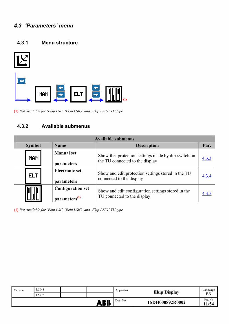
4.3 ‘Parameters’ menu
4.3.1 Menu structure
L5048 Version L5975
Apparatus Ekip Display
Language
EN
ABBDoc. No 1SDH000892R0002
Pag. No
11/54
(1)
(1) Not available for ‘Ekip LSI’, ‘Ekip LSIG’ and ‘Ekip LSIG’ TU type
4.3.2 Available submenus
Available submenus
Symbol Name Description Par.
Manual set parameters
Show the protection settings made by dip-switch on the TU connected to the display
4.3.3
Electronic set parameters
Show and edit protection settings stored in the TU connected to the display
4.3.4
Configuration set parameters(1)
Show and edit configuration settings stored in the TU connected to the display
4.3.5
(1) Not available for ‘Ekip LSI’, ‘Ekip LSIG’ and ‘Ekip LSIG’ TU type

4.3.3 ‘Manual set parameters’ menu Accessing this menu is showed the protection setting made by dip-switch on the TU connected to the display.
4.3.3.1 Menu structure The submenus available are different depending of the TU type connected to the display. In case of use of ‘Ekip LSI’, ‘Ekip LSIG’ o ‘Ekip E-LSIG’ TU type the following structure is available:
(1
L5048 Version L5975
Apparatus Ekip Display
Language
EN
ABBDoc. No 1SDH000892R0002
Pag. No
12/54
) (1) Not available for ‘Ekip LSI’ and ‘Ekip E-LSIG’ TU type In case of use of ‘Ekip M-LRIU’ TU type the following structure is available:

4.3.3.2 Available submenus The submenus available are different depending of the TU type connected to the display. In case of use of ‘Ekip LSI’, ‘Ekip LSIG’ or ‘Ekip E-LSIG’ TU type the following structure is available:
Available submenus
Symbol Name Description Par.
L protection
Show the manual settings for protection against overloading made by dip-switch on the TU connected to the display
4.3.3.3
S protection
Show the manual settings for protection against short circuit with adjustable delay made by dip-switch on the TU connected to the display
4.3.3.4
I protection
Show the manual settings for istantaneous protection against short circuit made by dip-switch on the TU connected to the display
4.3.3.5
G protection(1)
Show the manual settings for protection against ground fault made by dip-switch on the TU connected to the display
4.3.3.6
(1) Not available for ‘Ekip LSI’ and ‘Ekip E-LSIG’ TU type In case of use of ‘Ekip M-LRIU’ TU type the following structure is available:
Available submenus
Symbol Name Description Par.
L protection
Show the manual settings for protection against overloading made by dip-switch on the TU connected to the display
4.3.3.3
R (jam) protection
Show the manual settings for protection against rotor jam made by dip-switch on the TU connected to the display
4.3.3.7
I protection
Show the manual settings for istantaneous protection against short circuit made by dip-switch on the TU connected to the display
4.3.3.5
U (phase loss) protection
Show the manual settings for protection against phase loss made by dip-switch on the TU connected to the display
4.3.3.8
L5048 Version L5975
Apparatus Ekip Display
Language
EN
ABBDoc. No 1SDH000892R0002
Pag. No
13/54

4.3.3.3 Manual ‘L’ protection parameters Show the manual settings for protection against overload ‘L’ made by dip-switch on the TU connected to the display. This protection is available for ‘Ekip LSI’, ‘Ekip LSIG’, ‘Ekip M-LRIU’ and ‘Ekip E-LSIG’ TU type.
4.3.3.3.1 Structure
…
L5048 Version L5975
Apparatus Ekip Display
Language
EN
ABBDoc. No 1SDH000892R0002
Pag. No
14/54
(1)
1) Not available for ‘Ekip M-LRIU’ and ‘Ekip E-LSIG’ TU type (
4.3.3.3.2 Available parameters
Symbol Name
Manual L threshold
Manual L time
Thermal memory status (1)
) Not available for ‘Ekip M-LRIU’ and ‘Ekip E-LSIG’ TU type (1
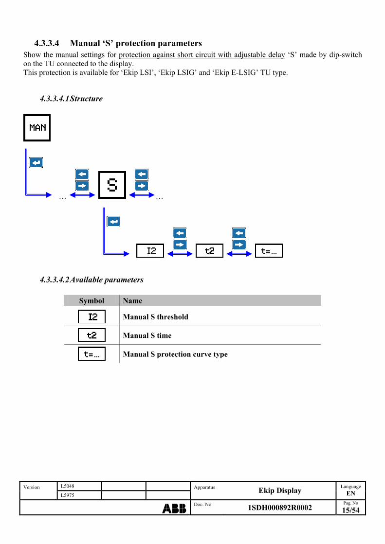
4.3.3.4 Manual ‘S’ protection parameters Show the manual settings for protection against short circuit with adjustable delay ‘S’ made by dip-switch on the TU connected to the display. This protection is available for ‘Ekip LSI’, ‘Ekip LSIG’ and ‘Ekip E-LSIG’ TU type.
4.3.3.4.1 Structure
… …
L5048 Version L5975
Apparatus Ekip Display
Language
EN
ABBDoc. No 1SDH000892R0002
Pag. No
15/54
4.3.3.4.2 Available parameters
Symbol Name
Manual S threshold
Manual S time
Manual S protection curve type

4.3.3.5 Manual ‘I’ protection parameters Show the manual settings for istantaneous protection against short circuit ‘I’ made by dip-switch on the TU connected to the display. This protection is available for ‘Ekip LSI’, ‘Ekip LSIG’, ‘Ekip M-LRIU’ and ‘Ekip E-LSIG’ TU type.
4.3.3.5.1 Structure
… …
4.3.3.5.2 Available parameters
Symbol Name
Manual I protection status
L5048 Version L5975
Apparatus Ekip Display
Language
EN
ABBDoc. No 1SDH000892R0002
Pag. No
16/54

4.3.3.6 Manual ‘G’ protection parameters Show the manual settings for protection against ground fault ‘G’ made by dip-switch on the TU connected to the display. This protection is available only for ‘Ekip LSIG’ TU type.
4.3.3.6.1 Structure
…
L5048 Version L5975
Apparatus Ekip Display
Language
EN
ABBDoc. No 1SDH000892R0002
Pag. No
17/54
4.3.3.6.2 Available parameters
Symbol Name
Manual G threshold
Manual G time

4.3.3.7 Manual ‘R (jam)’ protection parameters Show the manual settings for protection against rotor jam ‘R (jam)’ made by dip-switch on the TU connected to the display. This protection is available only for ‘Ekip M-LRIU’ TU type.
4.3.3.7.1 Structure
… …
L5048 Version L5975
Apparatus Ekip Display
Language
EN
ABBDoc. No 1SDH000892R0002
Pag. No
18/54
4.3.3.7.2 Available parameters
Symbol Name
Manual R (jam) threshold
Manual R (jam) time

4.3.3.8 Protection parameters ‘U (phase loss)’ manuals Show the manual settings for protection against phase loss ‘U (phase loss)’ made by dip-switch on the TU connected to the display. This protection is available only for ‘Ekip M-LRIU’ TU type.
4.3.3.8.1 Structure
…
4.3.3.8.2 Available parameters
Symbol Name
Manual U (phase loss) protection status
L5048 Version L5975
Apparatus Ekip Display
Language
EN
ABBDoc. No 1SDH000892R0002
Pag. No
19/54
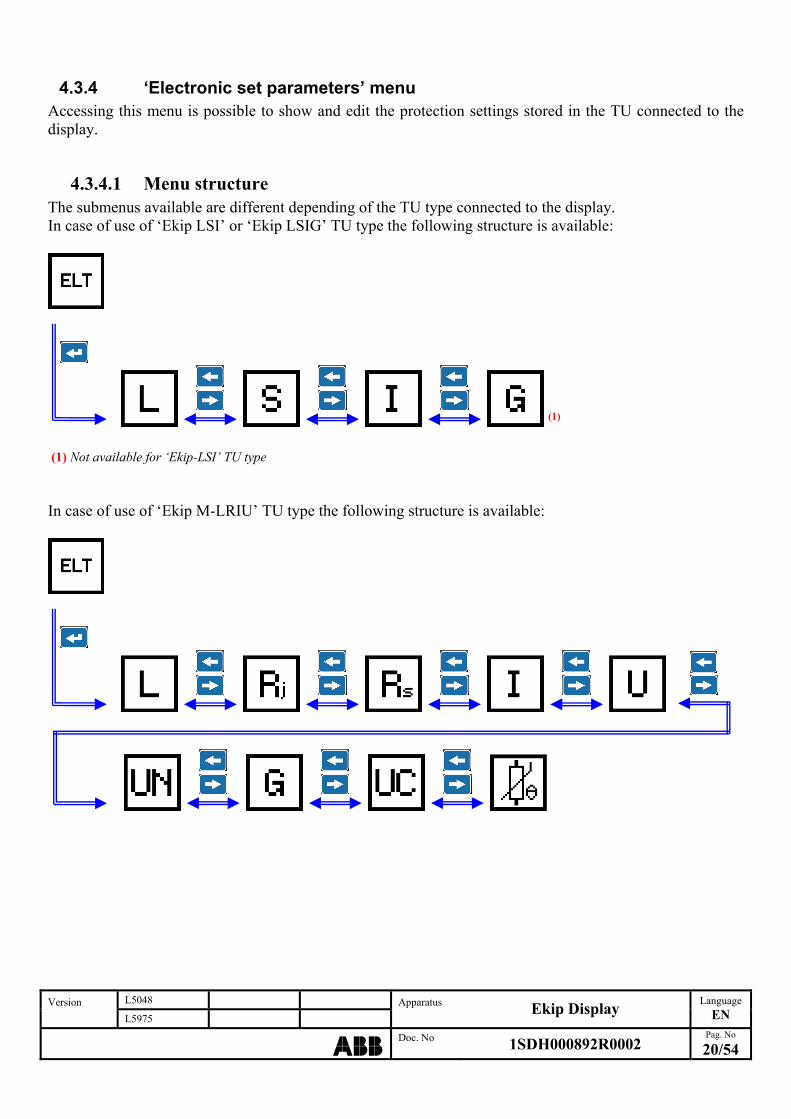
4.3.4 ‘Electronic set parameters’ menu Accessing this menu is possible to show and edit the protection settings stored in the TU connected to the display.
4.3.4.1 Menu structure The submenus available are different depending of the TU type connected to the display. In case of use of ‘Ekip LSI’ or ‘Ekip LSIG’ TU type the following structure is available:
(1) (1) Not available for ‘Ekip-LSI’ TU type In case of use of ‘Ekip M-LRIU’ TU type the following structure is available:
L5048 Version L5975
Apparatus Ekip Display
Language
EN
ABBDoc. No 1SDH000892R0002
Pag. No
20/54
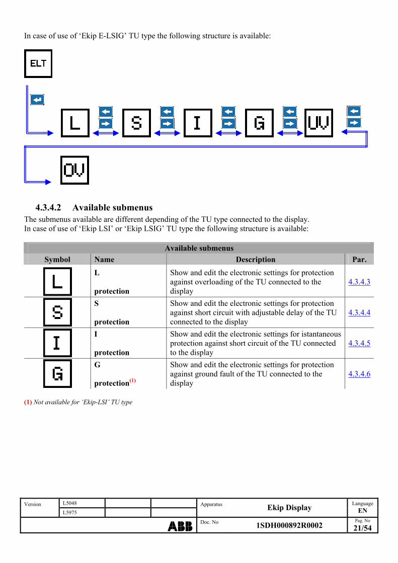
In case of use of ‘Ekip E-LSIG’ TU type the following structure is available:
L5048 Version L5975
Apparatus Ekip Display
Language
EN
ABBDoc. No 1SDH000892R0002
Pag. No
21/54
4.3.4.2 Available submenus The submenus available are different depending of the TU type connected to the display. In case of use of ‘Ekip LSI’ or ‘Ekip LSIG’ TU type the following structure is available:
Available submenus
Symbol Name Description Par.
L protection
Show and edit the electronic settings for protection against overloading of the TU connected to the display
4.3.4.3
S protection
Show and edit the electronic settings for protection against short circuit with adjustable delay of the TU connected to the display
4.3.4.4
I protection
Show and edit the electronic settings for istantaneous protection against short circuit of the TU connected to the display
4.3.4.5
G protection(1)
Show and edit the electronic settings for protection against ground fault of the TU connected to the display
4.3.4.6
( 1) Not available for ‘Ekip-LSI’ TU type
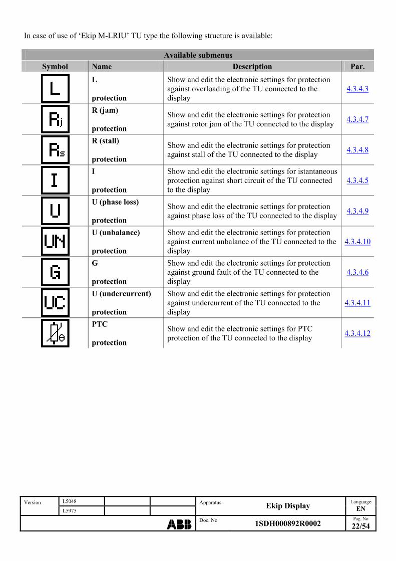
In case of use of ‘Ekip M-LRIU’ TU type the following structure is available:
Available submenus
Symbol Name Description Par.
L protection
Show and edit the electronic settings for protection against overloading of the TU connected to the display
4.3.4.3
R (jam) protection
Show and edit the electronic settings for protection against rotor jam of the TU connected to the display
4.3.4.7
R (stall) protection
Show and edit the electronic settings for protection against stall of the TU connected to the display
4.3.4.8
I protection
Show and edit the electronic settings for istantaneous protection against short circuit of the TU connected to the display
4.3.4.5
U (phase loss) protection
Show and edit the electronic settings for protection against phase loss of the TU connected to the display
4.3.4.9
U (unbalance) protection
Show and edit the electronic settings for protection against current unbalance of the TU connected to the display
4.3.4.10
G protection
Show and edit the electronic settings for protection against ground fault of the TU connected to the display
4.3.4.6
U (undercurrent) protection
Show and edit the electronic settings for protection against undercurrent of the TU connected to the display
4.3.4.11
PTC protection
Show and edit the electronic settings for PTC protection of the TU connected to the display
4.3.4.12
L5048 Version L5975
Apparatus Ekip Display
Language
EN
ABBDoc. No 1SDH000892R0002
Pag. No
22/54

In case of use of ‘Ekip E-LSIG’ TU type the following structure is available:
Available submenus
Symbol Name Description Par.
L protection
Show and edit the electronic settings for protection against overloading of the TU connected to the display
4.3.4.3
S protection
Show and edit the electronic settings for protection against short circuit with adjustable delay of the TU connected to the display
4.3.4.4
I protection
Show and edit the electronic settings for istantaneous protection against short circuit of the TU connected to the display
4.3.4.5
G protection
Show and edit the electronic settings for protection against ground fault of the TU connected to the display
4.3.4.6
UV protection
Show and edit the electronic settings for protection against undervoltage of the TU connected to the display
4.3.4.13
OV protection
Show and edit the electronic settings for protection against overvoltage of the TU connected to the display
4.3.4.14
L5048 Version L5975
Apparatus Ekip Display
Language
EN
ABBDoc. No 1SDH000892R0002
Pag. No
23/54

4.3.4.3 Electronic ‘L’ protection parameters Show and edit the electronic settings for protection against overload ‘L’ of the TU connected to the display. This protection is available for ‘Ekip LSI’, ‘Ekip LSIG’, ‘Ekip M-LRIU’ and ‘Ekip E-LSIG’ TU type.
4.3.4.3.1 Structure
…
L5048 Version L5975
Apparatus Ekip Display
Language
EN
ABBDoc. No 1SDH000892R0002
Pag. No
24/54
(1)
) Not available for ‘Ekip M-LRIU’ and ‘Ekip E-LSIG’ TU type (1
4.3.4.3.2 Available parameters
Symbol Name
Electronic L threshold
Electronic L time
Thermal memory status (1)
1) Not available for ‘Ekip M-LRIU’ and ‘Ekip E-LSIG’ TU type (
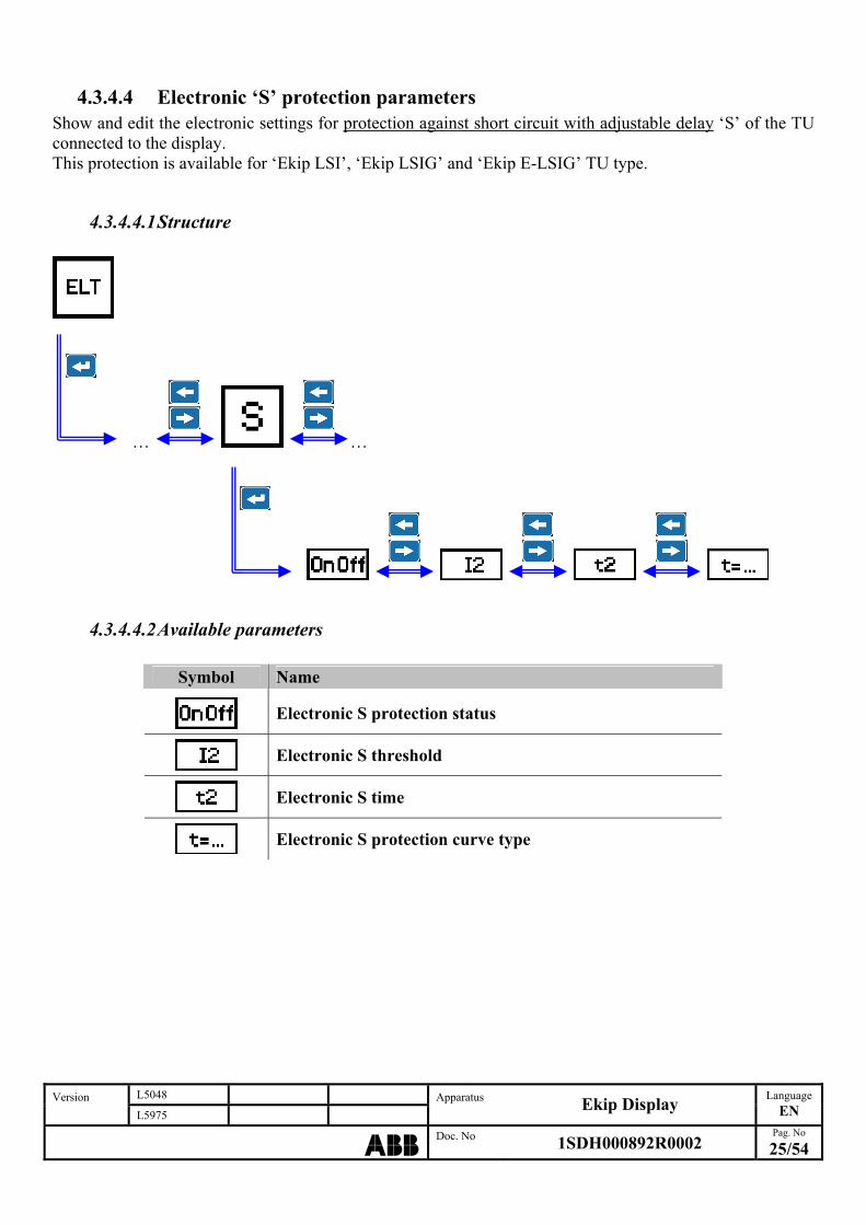
4.3.4.4 Electronic ‘S’ protection parameters Show and edit the electronic settings for protection against short circuit with adjustable delay ‘S’ of the TU connected to the display. This protection is available for ‘Ekip LSI’, ‘Ekip LSIG’ and ‘Ekip E-LSIG’ TU type.
4.3.4.4.1 Structure
… …
L5048 Version L5975
Apparatus Ekip Display
Language
EN
ABBDoc. No 1SDH000892R0002
Pag. No
25/54
4.3.4.4.2 Available parameters
Symbol Name
Electronic S protection status
Electronic S threshold
Electronic S time
Electronic S protection curve type
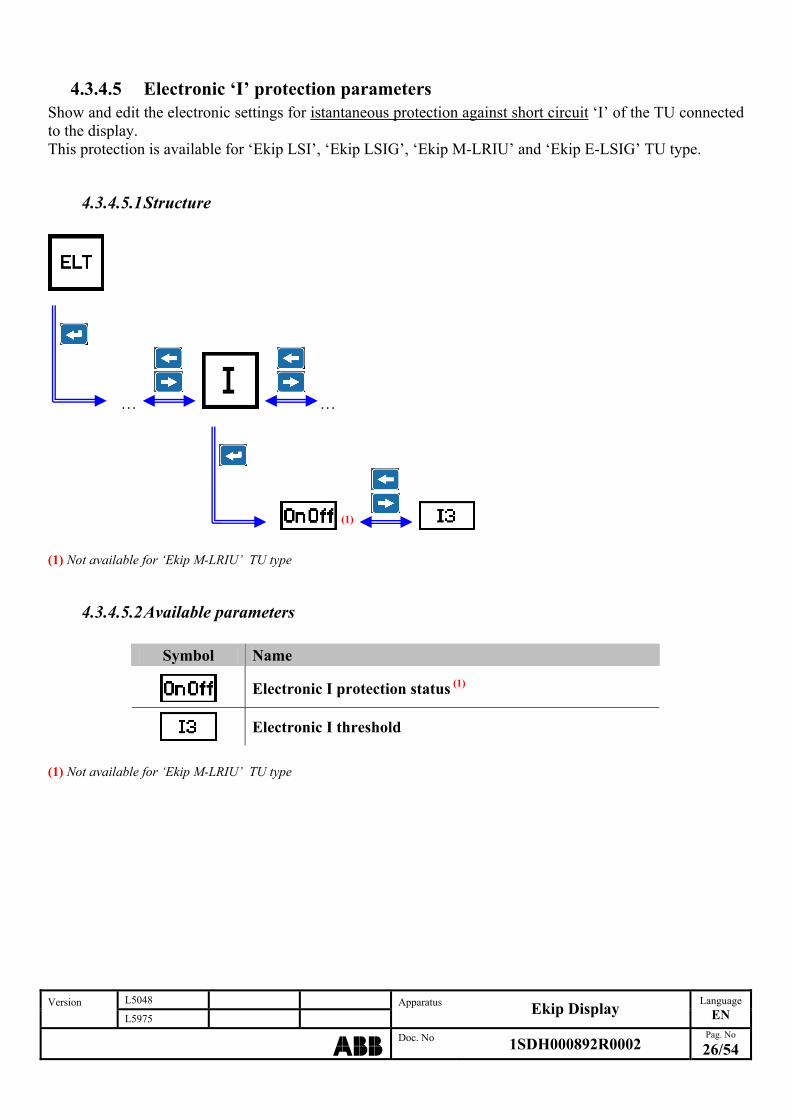
4.3.4.5 Electronic ‘I’ protection parameters Show and edit the electronic settings for istantaneous protection against short circuit ‘I’ of the TU connected to the display. This protection is available for ‘Ekip LSI’, ‘Ekip LSIG’, ‘Ekip M-LRIU’ and ‘Ekip E-LSIG’ TU type.
4.3.4.5.1 Structure
… …
(1)
) Not available for ‘Ekip M-LRIU’ TU type (1
4.3.4.5.2 Available parameters
Symbol Name
Electronic I protection status (1)
Electronic I threshold
) Not available for ‘Ekip M-LRIU’ TU type (1
L5048 Version L5975
Apparatus Ekip Display
Language
EN
ABBDoc. No 1SDH000892R0002
Pag. No
26/54
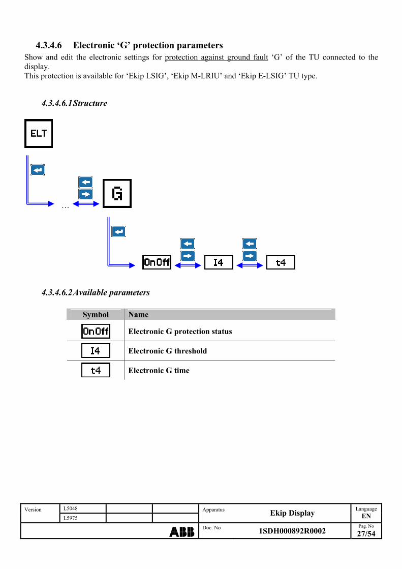
4.3.4.6 Electronic ‘G’ protection parameters Show and edit the electronic settings for protection against ground fault ‘G’ of the TU connected to the display. This protection is available for ‘Ekip LSIG’, ‘Ekip M-LRIU’ and ‘Ekip E-LSIG’ TU type.
4.3.4.6.1 Structure
…
L5048 Version L5975
Apparatus Ekip Display
Language
EN
ABBDoc. No 1SDH000892R0002
Pag. No
27/54
4.3.4.6.2 Available parameters
Symbol Name
Electronic G protection status
Electronic G threshold
Electronic G time
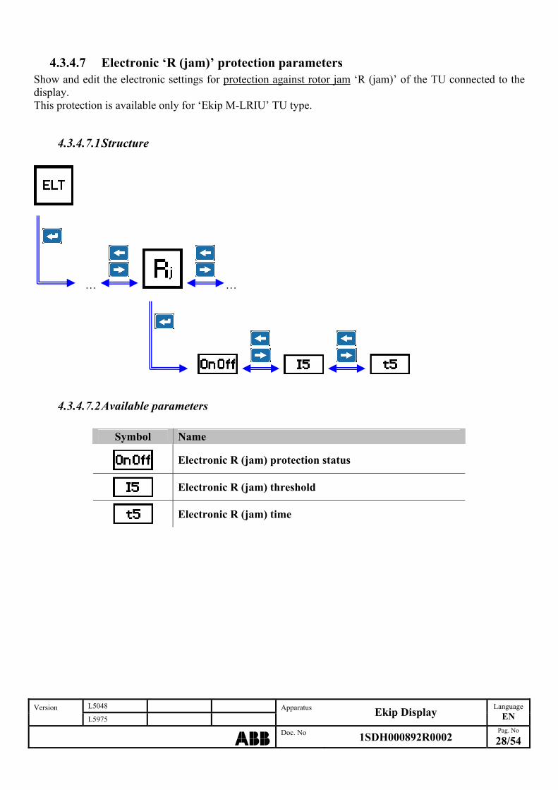
4.3.4.7 Electronic ‘R (jam)’ protection parameters Show and edit the electronic settings for protection against rotor jam ‘R (jam)’ of the TU connected to the display. This protection is available only for ‘Ekip M-LRIU’ TU type.
4.3.4.7.1 Structure
… …
L5048 Version L5975
Apparatus Ekip Display
Language
EN
ABBDoc. No 1SDH000892R0002
Pag. No
28/54
4.3.4.7.2 Available parameters
Symbol Name
Electronic R (jam) protection status
Electronic R (jam) threshold
Electronic R (jam) time

4.3.4.8 Electronic ‘R (stall)’ protection parameters Show and edit the electronic settings for protection against stall ‘R (stall)’ of the TU connected to the display. This protection is available only for ‘Ekip M-LRIU’ TU type.
4.3.4.8.1 Structure
… …
L5048 Version L5975
Apparatus Ekip Display
Language
EN
ABBDoc. No 1SDH000892R0002
Pag. No
29/54
4.3.4.8.2 Available parameters
Symbol Name
Electronic R (stall) protection status
Electronic R (stall) threshold
Electronic R (stall) time
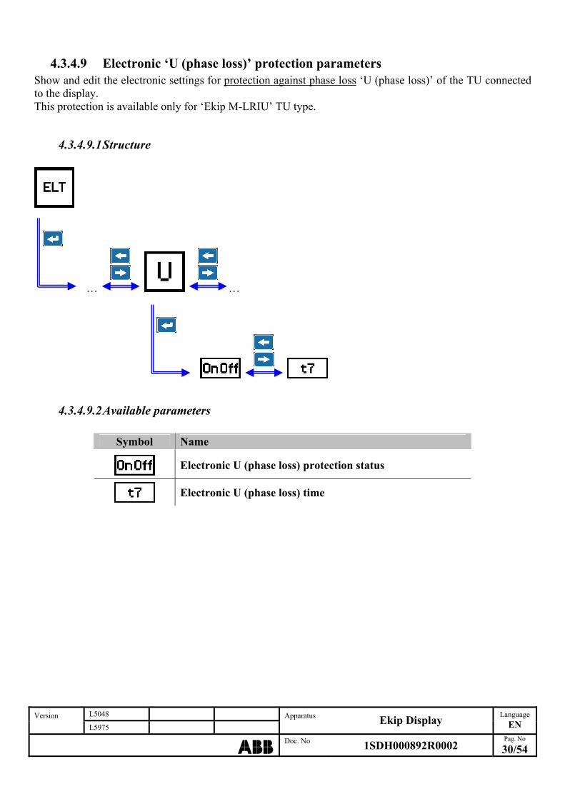
4.3.4.9 Electronic ‘U (phase loss)’ protection parameters Show and edit the electronic settings for protection against phase loss ‘U (phase loss)’ of the TU connected to the display. This protection is available only for ‘Ekip M-LRIU’ TU type.
4.3.4.9.1 Structure
… …
L5048 Version L5975
Apparatus Ekip Display
Language
EN
ABBDoc. No 1SDH000892R0002
Pag. No
30/54
4.3.4.9.2 Available parameters
Symbol Name
Electronic U (phase loss) protection status
Electronic U (phase loss) time
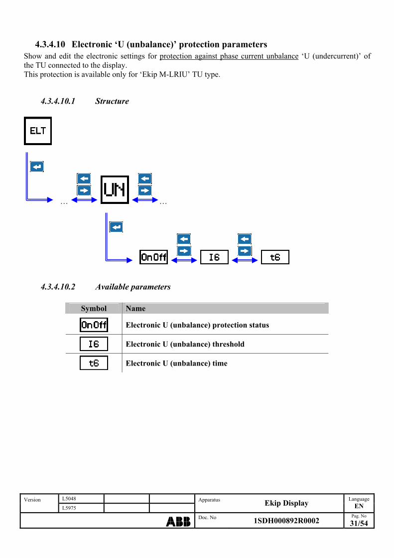
4.3.4.10 Electronic ‘U (unbalance)’ protection parameters Show and edit the electronic settings for protection against phase current unbalance ‘U (undercurrent)’ of the TU connected to the display. This protection is available only for ‘Ekip M-LRIU’ TU type.
4.3.4.10.1 Structure
… …
L5048 Version L5975
Apparatus Ekip Display
Language
EN
ABBDoc. No 1SDH000892R0002
Pag. No
31/54
4.3.4.10.2 Available parameters
Symbol Name
Electronic U (unbalance) protection status
Electronic U (unbalance) threshold
Electronic U (unbalance) time
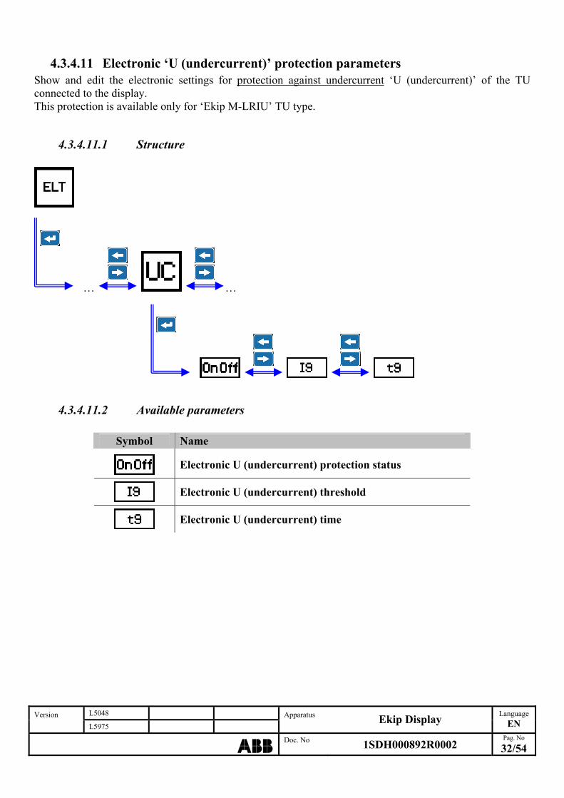
4.3.4.11 Electronic ‘U (undercurrent)’ protection parameters Show and edit the electronic settings for protection against undercurrent ‘U (undercurrent)’ of the TU connected to the display. This protection is available only for ‘Ekip M-LRIU’ TU type.
4.3.4.11.1 Structure
… …
L5048 Version L5975
Apparatus Ekip Display
Language
EN
ABBDoc. No 1SDH000892R0002
Pag. No
32/54
4.3.4.11.2 Available parameters
Symbol Name
Electronic U (undercurrent) protection status
Electronic U (undercurrent) threshold
Electronic U (undercurrent) time
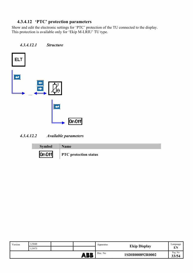
4.3.4.12 ‘PTC’ protection parameters Show and edit the electronic settings for ‘PTC’ protection of the TU connected to the display. This protection is available only for ‘Ekip M-LRIU’ TU type.
4.3.4.12.1 Structure
…
4.3.4.12.2 Available parameters
Symbol Name
PTC protection status
L5048 Version L5975
Apparatus Ekip Display
Language
EN
ABBDoc. No 1SDH000892R0002
Pag. No
33/54

4.3.4.13 Electronic ‘UV’ protection parameters Show and edit the electronic settings for protection against undervoltage ‘UV’ of the TU connected to the display. This protection is available only for ‘Ekip E-LSIG’ TU type.
4.3.4.13.1 Structure
… …
L5048 Version L5975
Apparatus Ekip Display
Language
EN
ABBDoc. No 1SDH000892R0002
Pag. No
34/54
4.3.4.13.2 Available parameters
Symbol Name
Electronic UV protection status
Electronic UV protection trip status
Electronic UV threshold
Electronic UV time

4.3.4.14 Electronic ‘OV’ protection parameters Show and edit the electronic settings for protection against overvoltage ‘OV’ of the TU connected to the display. This protection is available only for ‘Ekip E-LSIG’ TU type.
4.3.4.14.1 Structure
…
L5048 Version L5975
Apparatus Ekip Display
Language
EN
ABBDoc. No 1SDH000892R0002
Pag. No
35/54
4.3.4.14.2 Available parameters
Symbol Name
Electronic OV protection status
Electronic OV protection trip status
Electronic OV threshold
Electronic OV time

4.3.4.15 Electronic protection parameters programming example
1. From default page:
…
2. press ‘Enter’ for access to main menu:
3. move through main menu with ‘Right’ and ‘Left’ buttons and press ‘Enter’ to select ‘Parameters’ menu:
4. press ‘Enter’ to select ‘Electronic set parameters’ menu:
5. move through ‘Electronic set parameters’ menu and select ‘Electronic L protection’ submenu:
L5048 Version L5975
Apparatus Ekip Display
Language
EN
ABBDoc. No 1SDH000892R0002
Pag. No
36/54

6. press ‘Enter’ to select ‘Electronic L threshold (I1) parameter:
7. using ‘Right’ and ‘Left’ buttons select the wanted value:
8. press ‘Enter’ to confirm the parameter selection:
9. press ‘Esc’ to go back to the previous page.
4.3.5 ‘Configuration set parameters’ menu Accessing this menu is possible to show and edit the configuration settings stored in the TU connected to the display.
4.3.5.1 Menu structure The parameters available are different depending of the TU type connected to the display. In case of use of ‘Ekip E-LSIG’ TU type the following structure is available:
L5048 Version L5975
Apparatus Ekip Display
Language
EN
ABBDoc. No 1SDH000892R0002
Pag. No
37/54
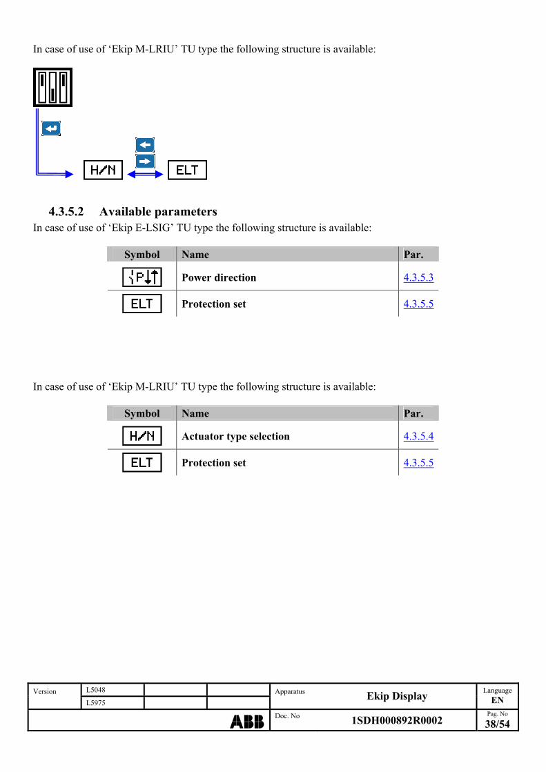
In case of use of ‘Ekip M-LRIU’ TU type the following structure is available:
L5048 Version L5975
Apparatus Ekip Display
Language
EN
ABBDoc. No 1SDH000892R0002
Pag. No
38/54
4.3.5.2 Available parameters In case of use of ‘Ekip E-LSIG’ TU type the following structure is available:
Symbol Name Par.
Power direction 4.3.5.3
Protection set 4.3.5.5
In case of use of ‘Ekip M-LRIU’ TU type the following structure is available:
Symbol Name Par.
Actuator type selection 4.3.5.4
Protection set 4.3.5.5
L5048 Version L5975
Apparatus Ekip Display
Language
EN
ABBDoc. No 1SDH000892R0002
Pag. No
39/54
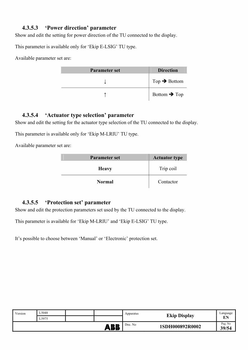
4.3.5.3 ‘Power direction’ parameter Show and edit the setting for power direction of the TU connected to the display. This parameter is available only for ‘Ekip E-LSIG’ TU type. Available parameter set are:
Parameter set Direction
↓ Top Bottom
↑ Bottom Top
4.3.5.4 ‘Actuator type selection’ parameter Show and edit the setting for the actuator type selection of the TU connected to the display. This parameter is available only for ‘Ekip M-LRIU’ TU type. Available parameter set are:
Parameter set Actuator type
Heavy Trip coil
Normal Contactor
4.3.5.5 ‘Protection set’ parameter Show and edit the protection parameters set used by the TU connected to the display. This parameter is available for ‘Ekip M-LRIU’ and ‘Ekip E-LSIG’ TU type. It’s possible to choose between ‘Manual’ or ‘Electronic’ protection set.
4.4 ‘Communication’ menu
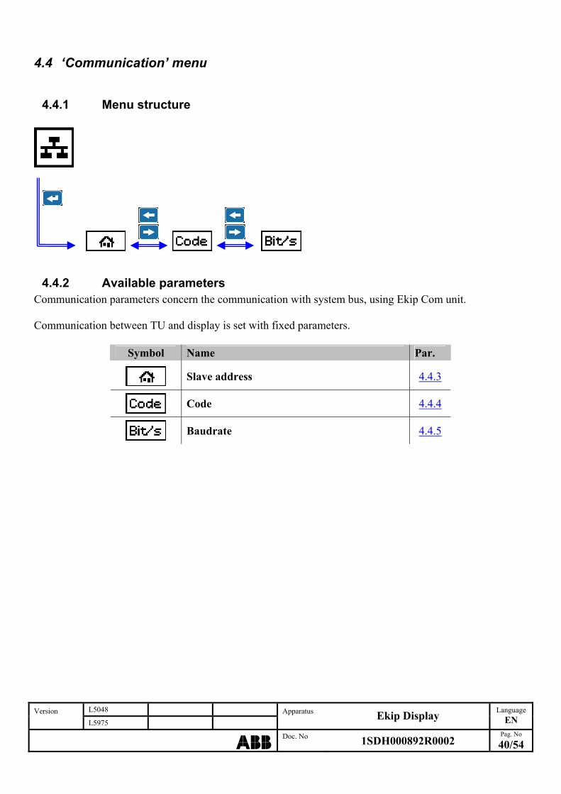
4.4.1 Menu structure
L5048 Version L5975
Apparatus Ekip Display
Language
EN
ABBDoc. No 1SDH000892R0002
Pag. No
40/54
4.4.2 Available parameters Communication parameters concern the communication with system bus, using Ekip Com unit. Communication between TU and display is set with fixed parameters.
Symbol Name Par.
Slave address 4.4.3
Code 4.4.4
Baudrate 4.4.5

L5048 Version L5975
Apparatus Ekip Display
Language
EN
ABBDoc. No 1SDH000892R0002
Pag. No
41/54
4.4.3 ‘Slave address’ parameter Show and edit Modbus address of the TU connected to the display. It’s possible to set any address between 1 and 247.
4.4.4 ‘Code’ parameter Show and edit Modbus protocol coding parameters of the TU connected to the display. Available parameters set are:
Parameter set Parity Bit number Stop bit
E,8,1 Even 8 1
O,8,1 Odd 8 1
N,8,2 None 8 2
N,8,1 None 8 1
4.4.5 ‘Baudrate’ parameter Show and edit the communication speed parameter of the TU connected to the display. It’s possible to set a baudrate equal to 9600 bit/s or 19200 bit/s.
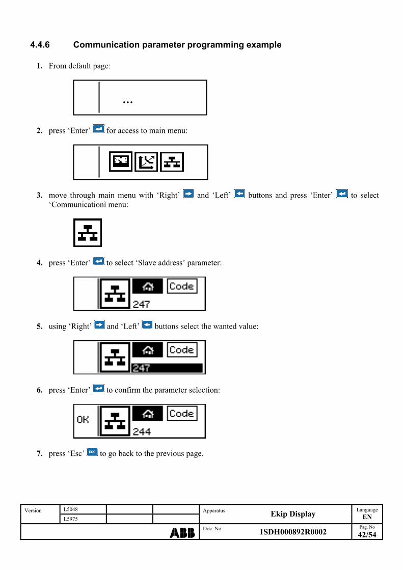
4.4.6 Communication parameter programming example
1. From default page:
…
2. press ‘Enter’ for access to main menu:
3. move through main menu with ‘Right’ and ‘Left’ buttons and press ‘Enter’ to select
‘Communicationì menu:
4. press ‘Enter’ to select ‘Slave address’ parameter:
5. using ‘Right’ and ‘Left’ buttons select the wanted value:
6. press ‘Enter’ to confirm the parameter selection:
7. press ‘Esc’ to go back to the previous page.
L5048 Version L5975
Apparatus Ekip Display
Language
EN
ABBDoc. No 1SDH000892R0002
Pag. No
42/54
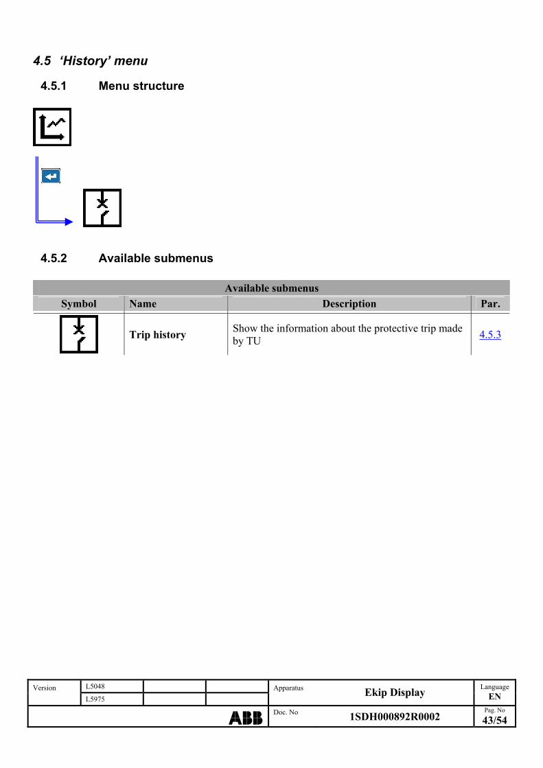
4.5 ‘History’ menu
4.5.1 Menu structure
L5048 Version L5975
Apparatus Ekip Display
Language
EN
ABBDoc. No 1SDH000892R0002
Pag. No
43/54
4.5.2 Available submenus
Available submenus
Symbol Name Description Par.
Trip history Show the information about the protective trip made by TU
4.5.3

4.5.3 ‘Trip history’ menu Show the information about all protective trip made by TU. Available information are:
Trip type Number of trip
Phase current value or voltage value(1)
at the time of the trip
(1) Available for ‘Ekip E-LSIG’ TU type only The higher ‘Trip number’ indicates the last trip occured. The trip showed at ‘Trip history’ menu access is the last trip occured. Is possible to scroll the trip using ‘Right’ and ‘Left’ buttons.
L5048 Version L5975
Apparatus Ekip Display
Language
EN
ABBDoc. No 1SDH000892R0002
Pag. No
44/54
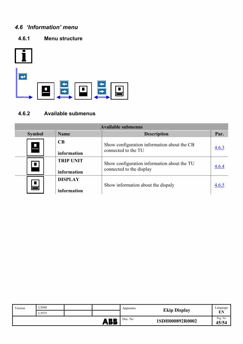
4.6 ‘Information’ menu
4.6.1 Menu structure
L5048 Version L5975
Apparatus Ekip Display
Language
EN
ABBDoc. No 1SDH000892R0002
Pag. No
45/54
4.6.2 Available submenus
Available submenus
Symbol Name Description Par.
CB information
Show configuration information about the CB connected to the TU
4.6.3
TRIP UNIT information
Show configuration information about the TU connected to the display
4.6.4
DISPLAY information
Show information about the dispaly 4.6.5

4.6.3 ‘CB information’ menu Show the following information about CB:
L5048 Version L5975
Apparatus Ekip Display
Language
EN
ABBDoc. No 1SDH000892R0002
Pag. No
46/54
CB serial number Normative standard
CB type
In size
Configuration
4.6.4 ‘TRIP UNIT information’ menu Show the following information about TU:
TU type TU SW version
Test date
TU serial number
4.6.5 ‘DISPLAY information’ menu Consente la visualizzazione delle seguenti informazioni relative al display:
Display SW version
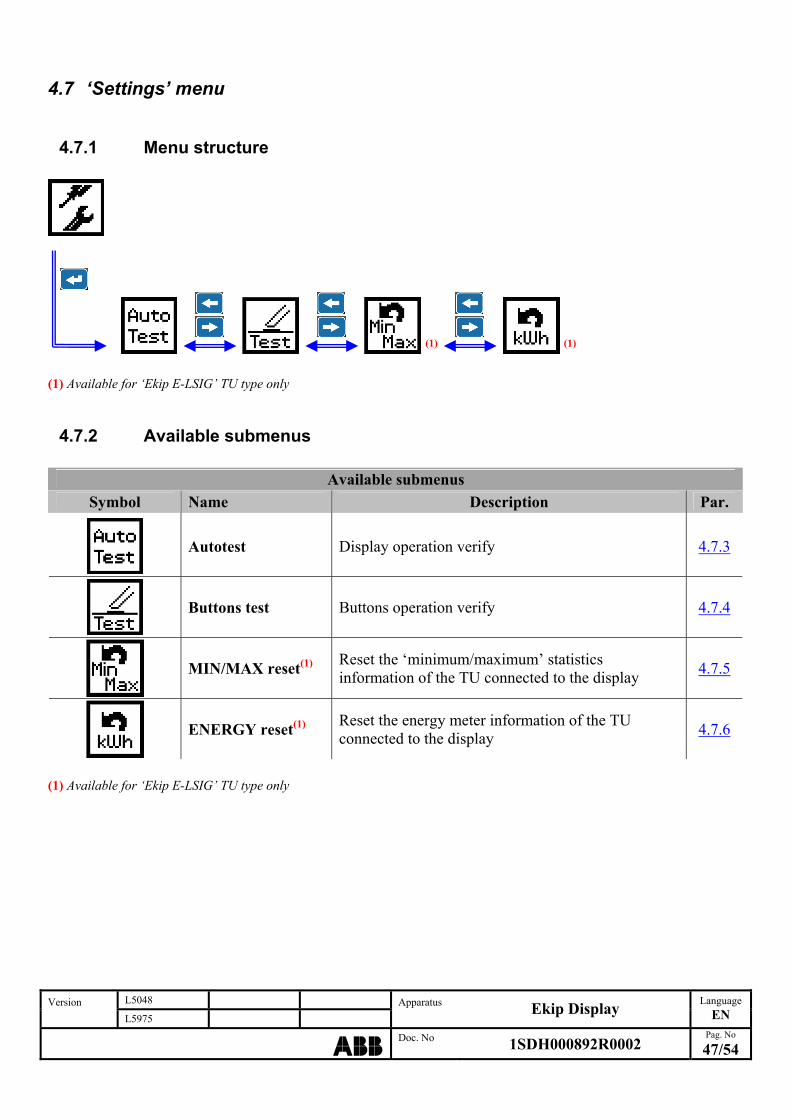
4.7 ‘Settings’ menu
4.7.1 Menu structure
(1) (1
L5048 Version L5975
Apparatus Ekip Display
Language
EN
ABBDoc. No 1SDH000892R0002
Pag. No
47/54
) (1) Available for ‘Ekip E-LSIG’ TU type only
4.7.2 Available submenus
Available submenus
Symbol Name Description Par.
Autotest Display operation verify 4.7.3
Buttons test Buttons operation verify 4.7.4
MIN/MAX reset(1) Reset the ‘minimum/maximum’ statistics information of the TU connected to the display
4.7.5
ENERGY reset(1) Reset the energy meter information of the TU connected to the display
4.7.6
(1) Available for ‘Ekip E-LSIG’ TU type only
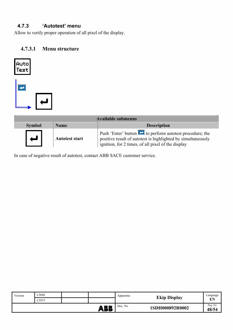
4.7.3 ‘Autotest’ menu Allow to verify proper operation of all pixel of the display.
4.7.3.1 Menu structure
L5048 Version L5975
Apparatus Ekip Display
Language
EN
ABBDoc. No 1SDH000892R0002
Pag. No
48/54
Available submenus
Symbol Name Description
Autotest start Push ‘Enter’ button to perform autotest procedure; the positive result of autotest is highlighted by simultaneously ignition, for 2 times, of all pixel of the display
In case of negative result of autotest, contact ABB SACE customer service.
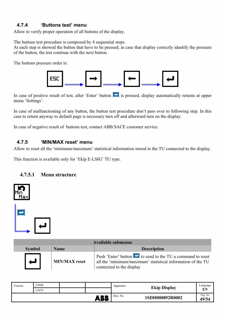
4.7.4 ‘Buttons test’ menu Allow to verify proper operation of all buttons of the display. The buttons test procedure is composed by 4 sequential steps. At each step is showed the button that have to be pressed; in case that display correctly identify the pressure of the button, the test continue with the next button. The buttons pressure order is:
In case of positive result of test, after ‘Enter’ button is pressed, display automatically returns at upper menu ‘Settings’. In case of malfunctioning of any button, the button test procedure don’t pass over to following step. In this case to return anyway to default page is necessary turn off and afterward turn on the display. In case of negative result of buttons test, contact ABB SACE customer service.
4.7.5 ‘MIN/MAX reset’ menu Allow to reset all the ‘minimum/maximum’ statistical information stored in the TU connected to the display. This function is available only for ‘Ekip E-LSIG’ TU type.
4.7.5.1 Menu structure
Available submenus
Symbol Name Description
MIN/MAX reset Push ‘Enter’ button to send to the TU a command to reset all the ‘minimum/maximum’ statistical information of the TU connected to the display
L5048 Version L5975
Apparatus Ekip Display
Language
EN
ABBDoc. No 1SDH000892R0002
Pag. No
49/54

4.7.6 ‘ENERGY reset’ menu Allow to reset all the energy measures stored in the TU connected to the display. This function is available only for ‘Ekip E-LSIG’ TU type.
4.7.6.1 Menu structure
L5048 Version L5975
Apparatus Ekip Display
Language
EN
ABBDoc. No 1SDH000892R0002
Pag. No
50/54
Available submenus
Symbol Name Description
ENERGY reset Push ‘Enter’ button to send to the TU a command to reset all the energy measures of the TU connected to the display
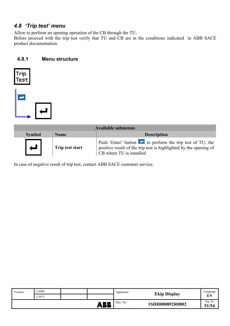
4.8 ‘Trip test’ menu Allow to perform an opening operation of the CB through the TU. Before proceed with the trip test verify that TU and CB are in the conditions indicated in ABB SACE product documentation.
4.8.1 Menu structure
L5048 Version L5975
Apparatus Ekip Display
Language
EN
ABBDoc. No 1SDH000892R0002
Pag. No
51/54
Available submenus
Symbol Name Description
Trip test start Push ‘Enter’ button to perform the trip test of TU; the positive result of the trip test is highlighted by the opening of CB where TU is installed
In case of negative result of trip test, contact ABB SACE customer service.
L5048 Version L5975
Apparatus Ekip Display
Language
EN
ABBDoc. No 1SDH000892R0002
Pag. No
52/54
5 Miscellaneous information
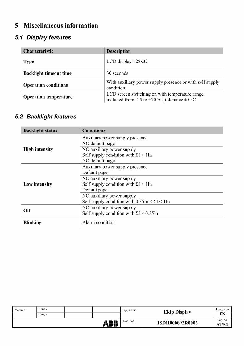
5.1 Display features
Characteristic Description
Type LCD display 128x32
Backlight timeout time 30 seconds
Operation conditions With auxiliary power supply presence or with self supply condition
Operation temperature LCD screen switching on with temperature range included from -25 to +70 °C, tolerance ±5 °C
5.2 Backlight features
Backlight status Conditions
Auxiliary power supply presence NO default page
High intensity NO auxiliary power supply Self supply condition with ΣI > 1In NO default page Auxiliary power supply presence Default page NO auxiliary power supply Self supply condition with ΣI > 1In Default page
Low intensity
NO auxiliary power supply Self supply condition with 0.35In < ΣI < 1In
Off NO auxiliary power supply Self supply condition with ΣI < 0.35In
Blinking Alarm condition
5.3 ‘Power’ led features
‘Power’ led state Description
On ‘Power mode’ TU configuration
Blinking with f = 2Hz ‘Wink’ command sent to TU
Blinking with f = 0,5Hz ‘Alive mode’ TU configuration
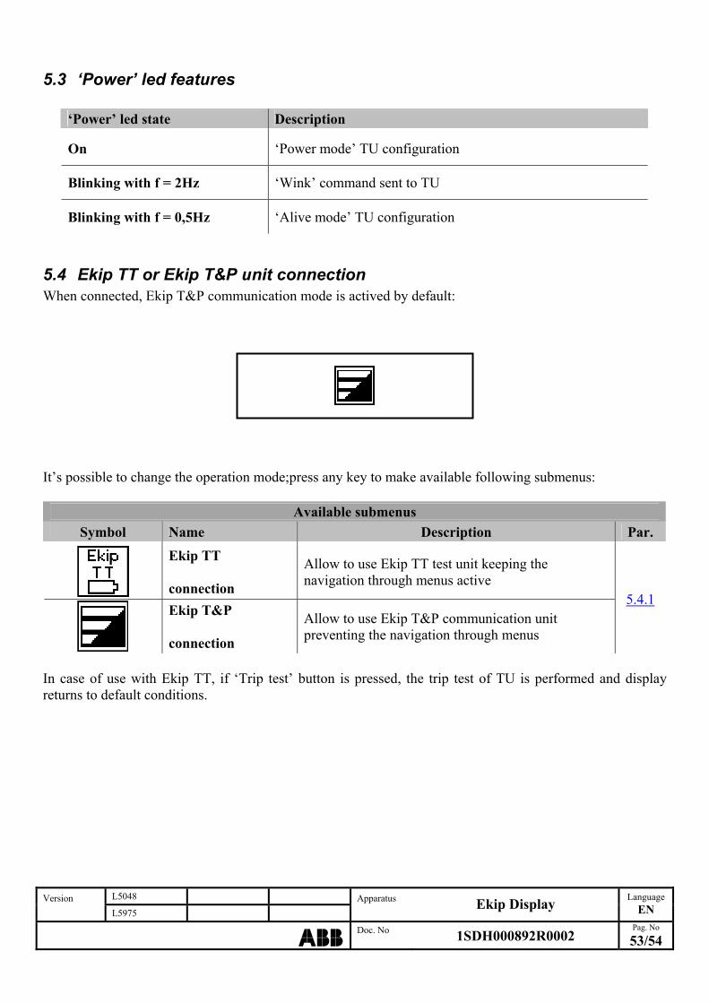
5.4 Ekip TT or Ekip T&P unit connection When connected, Ekip T&P communication mode is actived by default:
It’s possible to change the operation mode;press any key to make available following submenus:
Available submenus
Symbol Name Description Par.
Ekip TT connection
Allow to use Ekip TT test unit keeping the navigation through menus active
Ekip T&P connection
Allow to use Ekip T&P communication unit preventing the navigation through menus
5.4.1
In case of use with Ekip TT, if ‘Trip test’ button is pressed, the trip test of TU is performed and display returns to default conditions.
L5048 Version L5975
Apparatus Ekip Display
Language
EN
ABBDoc. No 1SDH000892R0002
Pag. No
53/54
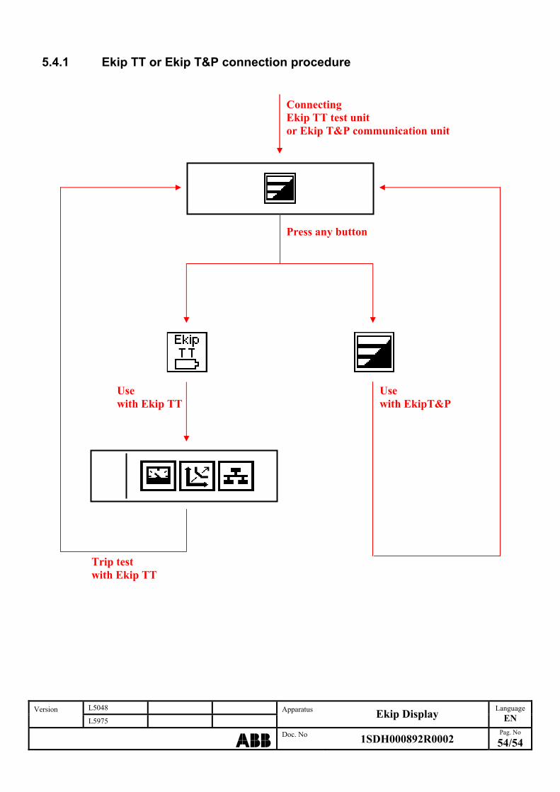
5.4.1 Ekip TT or Ekip T&P connection procedure
L5048 Version L
y Language
EN 5975
Apparatus Ekip Displa
ABBDoc. No 1SDH000892R0002
Pag. No
54/54
Connecting Ekip TT test unit or Ekip T&P communication unit
Press any button
Use with Ekip TT
Use with EkipT&P
Trip test with Ekip TT