Title: Unique Identifier: GUIDELINE ON THE 240-66418968 ... · PDF file3.6.7 Calculation of...
96
PCM Reference: 010-120 SCOT Study Committee Number/Name: Overhead Lines Guideline Technology Title: Unique Identifier: 240-66418968 Alternative Reference Number: <n/a> Area of Applicability: Engineering Documentation Type: Guideline Revision: 1 Total Pages: 96 Next Review Date: May 2020 GUIDELINE ON THE ELECTRICAL CO-ORDINATION OF PIPELINES AND POWER LINES Disclosure Classification: Controlled Disclosure Compiled by Approved by Authorized by Bart Druif Consultant Bharat Haridass Engineer Arthur Burger Chief Engineer - Electrical Date: Date: Date: Supported by SCOT/SC Riaz Vajeth SCOT/SC Chairperson Date:
-
Upload
phungkhuong -
Category
Documents
-
view
222 -
download
5
Transcript of Title: Unique Identifier: GUIDELINE ON THE 240-66418968 ... · PDF file3.6.7 Calculation of...

PCM Reference: 010-120
SCOT Study Committee Number/Name: Overhead Lines
Guideline Technology
Title: Unique Identifier: 240-66418968
Alternative Reference Number: <n/a>
Area of Applicability: Engineering
Documentation Type: Guideline
Revision: 1
Total Pages: 96
Next Review Date: May 2020
GUIDELINE ON THE ELECTRICAL CO-ORDINATION OF PIPELINES AND POWER LINES
Disclosure Classification: Controlled Disclosure
Compiled by Approved by Authorized by
Bart Druif
Consultant
Bharat Haridass
Engineer
Arthur Burger
Chief Engineer - Electrical
Date: Date: Date:
Supported by SCOT/SC
Riaz Vajeth
SCOT/SC Chairperson
Date:
Document Classification: Controlled Disclosure
Unique Identifier: 240-66418968
Revision: 1
GUIDELINE ON THE ELECTRICAL CO-ORDINATION OF PIPELINES AND POWER LINES
Page: 2 of 96
ESKOM COPYRIGHT PROTECTED
When downloaded from the WEB, this document is uncontrolled and the responsibility rests with the user
to ensure it is in line with the authorized version on the WEB.
Content
Page
1. Introduction..................................................................................................................................................5
2. Supporting clauses ......................................................................................................................................5
2.1 Scope .................................................................................................................................................5
2.1.1 Purpose..................................................................................................................................6
2.1.2 Applicability ............................................................................................................................6
2.2 Normative/informative references ......................................................................................................6
2.2.1 Normative...............................................................................................................................6
2.2.2 Informative .............................................................................................................................6
2.3 Definitions...........................................................................................................................................7
2.3.1 General ..................................................................................................................................7
2.3.2 Disclosure classification.........................................................................................................9
2.4 Abbreviations......................................................................................................................................9
2.5 Roles and responsibilities ................................................................................................................10
2.6 Process for monitoring .....................................................................................................................11
2.7 Related/supporting documents ........................................................................................................11
3. The Electrical Coordination of Pipelines and Power Lines........................................................................11
3.1 Statutory and Utility Requirements...................................................................................................11
3.1.1 Applicable legislation ...........................................................................................................11
3.1.2 Relevant statutory requirements ..........................................................................................11
3.1.3 Utility requirements for pipeline installations in Eskom's servitudes....................................12
3.2 Co-ordination and Management Procedure.....................................................................................14
3.2.1 Co-ordination........................................................................................................................14
3.2.2 Procedure for obtaining approval for new installations........................................................14
3.2.3 Cost of mitigation, protection and maintenance measures..................................................16
3.3 Coupling Limits.................................................................................................................................16
3.3.1 Origin of safety limits............................................................................................................16
3.3.2 Contact scenarios ................................................................................................................17
3.3.3 Limits relating to danger during fault conditions ..................................................................18
3.3.4 Limits relating to danger during steady state conditions......................................................20
3.3.5 Limits relating to damage of pipeline coatings.....................................................................20
3.3.6 Limits relating to damage of cathodic protection equipment ...............................................21
3.3.7 Limits relating to a.c. induced pipeline corrosion .................................................................21
3.3.8 Limits relating to d.c. leakage from pipelines and anode ground beds ...............................21
3.4 Assessment of the possible hazardous nature of an exposure .......................................................22
3.4.1 Data gathering .....................................................................................................................22
3.4.2 Establishing Zones of Influence ...........................................................................................23
3.5 Soil Resistivity Measurements .........................................................................................................30
3.5.1 General background ............................................................................................................30
3.5.2 Measurement methods ........................................................................................................31
3.5.3 Selection of measurement sites...........................................................................................33
3.5.4 Measurement precautions ...................................................................................................33
3.6 Calculation of pipeline voltages........................................................................................................34
3.6.1 General ................................................................................................................................34
3.6.2 Software packages ..............................................................................................................34
3.6.3 Inducing currents on a.c. power lines ..................................................................................35

Document Classification: Controlled Disclosure
Unique Identifier: 240-66418968
Revision: 1
GUIDELINE ON THE ELECTRICAL CO-ORDINATION OF PIPELINES AND POWER LINES
Page: 3 of 96
ESKOM COPYRIGHT PROTECTED
When downloaded from the WEB, this document is uncontrolled and the responsibility rests with the user
to ensure it is in line with the authorized version on the WEB.
3.6.4 Inducing currents on HVDC power lines..............................................................................43
3.6.5 Pipeline coating resistivity....................................................................................................43
3.6.6 Calculation of inductive coupling during a power system earth fault ...................................44
3.6.7 Calculation of conductive coupling from towers and substation earthing grids ...................44
3.6.8 Calculation of pipeline voltages during normal and emergency load conditions .................46
3.6.9 Determination of the most likely locations of pipeline voltage peaks...................................46
3.6.10 Calculation of d.c. leakage from pipelines and anode ground beds....................................47
3.6.11 Calculation of pipeline voltages with mitigation measures applied......................................48
3.6.12 Determination of current rating of d.c. decoupling devices, SPDs and cables....................49
3.7 Mitigation measures .........................................................................................................................50
3.7.1 Mitigation measures applicable to pipelines ........................................................................50
3.7.2 Mitigation measures applicable to power lines ....................................................................54
3.8 Safe working procedures in power line servitudes...........................................................................55
3.8.1 Appointment of Electrical Safety Officer (ESO) ...................................................................55
3.8.2 General Safe Working procedures ......................................................................................55
3.8.3 Daily measurements ............................................................................................................56
3.8.4 Temporary earthing..............................................................................................................57
3.8.5 Bonding of isolating flanges, joints and couplings ...............................................................57
3.8.6 Precautions during coating and lowering-in operations.......................................................58
3.8.7 Work stoppage.....................................................................................................................58
3.9 Inspection and testing and of pipeline a.c. mitigation components prior to commissioning ............58
3.10 Long term maintenance requirements of pipeline and power line a.c. mitigation components .......58
4. Authorization..............................................................................................................................................58
5. Revisions ...................................................................................................................................................59
6. Development team ....................................................................................................................................59
7. Acknowledgements ...................................................................................................................................59
Annex A – Checklists of particulars required....................................................................................................61
Annex B – Specification of Mitigation Components..........................................................................................65
Annex C – Worked Example.............................................................................................................................71
Annex D – Flowchart ........................................................................................................................................89
Annex E – Inspection sheet for a.c. mitigation components and servitude works ...........................................93
Figures
Figure 1: Typical contact scenarios with an energised pipeline and resulting body currents due to step and touch potentials ..........................................................................................................................17
Figure 2: Zone of influence for inductive coupling............................................................................................24
Figure 3: Exposure length Lp for crossings and non-parallel exposures..........................................................24
Figure 4: Separation distance vs. exposure length for urban and rural overhead lines...................................25
Figure 5: Separation distance vs. exposure length for urban power lines .......................................................26
Figure 6: Zone of influence for conductive coupling.........................................................................................27
Figure 7: Example of apparent resistivity graph and calculated soil layers......................................................32
Figure 8: Example of sliding fault current vs. tower number, 220 kV line ........................................................38
Figure 9: Example of current distribution for a 15 kA fault on the 10th tower of a 132 kV line ........................39

Document Classification: Controlled Disclosure
Unique Identifier: 240-66418968
Revision: 1
GUIDELINE ON THE ELECTRICAL CO-ORDINATION OF PIPELINES AND POWER LINES
Page: 4 of 96
ESKOM COPYRIGHT PROTECTED
When downloaded from the WEB, this document is uncontrolled and the responsibility rests with the user
to ensure it is in line with the authorized version on the WEB.
Figure 10: Calculation of electrode current, IE, with a fault inside a substation................................................40
Figure 11: Calculation of electrode current, IE , with a fault outside a substation ............................................41
Figure 12: Finding the worst fault position location on arbitrary exposures .....................................................42
Figure 13: Touch voltage resulting from conductive coupling from a faulted tower .........................................45
Figure 14: Voltage developed on uniformly exposed pipelines with no earthing .............................................46
Figure 15: Location of voltage peaks on non-uniform exposure pipeline with no earthing ..............................47
Figure 16: Example of the reduction of touch voltages by zinc ribbon installed in pipeline trench ..................48
Figure 17: Touch voltage resulting from conductive coupling from a faulted tower, with zinc ribbon installed near the faulted tower or grid ...........................................................................................49
Tables
Table 1: Limiting values for induced pipeline touch and step voltage during faults .........................................19
Table 2: Typical fault duration on Eskom power lines ......................................................................................20
Table 3: Approximate values of screening factors for inductive coupling ........................................................24
Table 4: Zone of influence for conductive coupling from substation earthing grids (0.2 sec fault duration) ....27
Table 5: Zone of influence for conductive coupling from power line towers (0.2 sec fault duration)................28
Table 6: Zone of influence for d.c. leakage (1 m ø pipe, diagonal crossing, 400 m span)...............................30
Table 7: Wenner soil resistivity soundings for inductive coupling studies........................................................31
Table 8: Wenner soil resistivity soundings for conductive coupling studies.....................................................32
Table 9: Wenner soil resistivity sounding for soil corrosivity studies................................................................32
Table 10: Standard Eskom overhead conductor ratings (50˚C).......................................................................36
Table 11: Nominal tower footing resistance (maximum) ..................................................................................39
Table 12: d.c. resistance of standard Eskom earth wires.................................................................................39
Table 13: Typical variation of coating resistivity and thickness........................................................................43
Table 14: Earthing resistance provided by gradient control wire, buried 2 m deep .........................................51
Table 15: Minimum vertical clearance underneath power line conductors ......................................................56

Document Classification: Controlled Disclosure
Unique Identifier: 240-66418968
Revision: 1
GUIDELINE ON THE ELECTRICAL CO-ORDINATION OF PIPELINES AND POWER LINES
Page: 5 of 96
ESKOM COPYRIGHT PROTECTED
When downloaded from the WEB, this document is uncontrolled and the responsibility rests with the user
to ensure it is in line with the authorized version on the WEB.
1. Introduction
As is the case in a number of other countries, increased urbanization in South Africa has been accompanied by an increasing number of applications by pipeline operators (water, gas, petroleum) to use the existing power line servitudes. These servitudes are particularly important to pipeline planners in urban areas where there may be few viable alternatives, but also in rural areas where the long tracts of land provided by power line servitudes are increasingly valued by pipeline operators. At the same time, the number of situations is on the increase where new power lines have to be installed next to existing pipelines.
When pipelines are located in (or cross) power line servitudes, there are a number of important issues to consider by both the electrical utility and the pipeline operators. During a power line fault, very high voltages can be induced in the pipeline, which can damage the cathodic protection systems and rupture the coating, and present a significant safety hazard for maintenance personnel. During normal operation the induced pipeline voltages are lower, but could still present a safety hazard due to the extended duration, and can result in accelerated corrosion of the pipeline.
From Eskom’s perspective, an additional concern is that the d.c. potentials of the pipeline’s cathodic protection system can produce leakage currents on power line structures resulting in electrolytic corrosion. This can generally be circumvented by insulating the earth wires of the pylons near pipelines. Though effective, this measure has cost implications for the utility and can, in the case of long parallelisms, present a safety hazard for live line workers and OPGW maintenance personnel if not carefully managed.
Internationally, safety and mitigation measures have been developed to cater for the co-use of power line servitudes by virtually all types of pipelines, as reflected in a number of IEEE, IEC, CEN, NACE and national standards. In South Africa however, there has been no local standard or guideline available to comprehensively deal with these issues, neither are there specific voltage (or current) limits recommended or regulated. This has led to either over- or under-design of mitigation measures, resulting in cases of damaged pipelines, corroded power line towers and earth wires, and electrical shocks experienced by maintenance personnel on both power line and pipeline infrastructure.
To address this issue, a SABS working group was established during 2010 representing the local electricity supply, pipeline and cathodic protection industries, with the objective of developing a standard or guideline. Due to the time scale involved in drafting SANS documents however, Eskom’s Line Engineering Services proposed to develop an in-house guideline to address the immediate needs. This guideline can then be submitted to the SABS for possible use in the new SANS document..
2. Supporting clauses
2.1 Scope
This Guideline addresses safety and interference issues arising from electrical coupling between a.c. or d.c. power lines and pipelines. It is applicable when pipelines cross power line servitudes, when pipelines and power lines share the same servitudes or when pipelines and power lines are installed in adjacent servitudes.
Capacitive, inductive and conductive coupling modes are considered during normal load and fault conditions, for overhead lines or underground cables coupling with pipelines above or below ground, when the phase-to-phase voltage exceeds 40 kV r.m.s. on overhead lines, or 10 kV r.m.s. on cables.
This Guideline provides interference limits, guidance on the calculation and measurement of coupling levels, protection and mitigation methods, safe installation practices in power line servitudes as well as the co-ordination and management procedures required between the respective authorities.
Document Classification: Controlled Disclosure
Unique Identifier: 240-66418968
Revision: 1
GUIDELINE ON THE ELECTRICAL CO-ORDINATION OF PIPELINES AND POWER LINES
Page: 6 of 96
ESKOM COPYRIGHT PROTECTED
When downloaded from the WEB, this document is uncontrolled and the responsibility rests with the user
to ensure it is in line with the authorized version on the WEB.
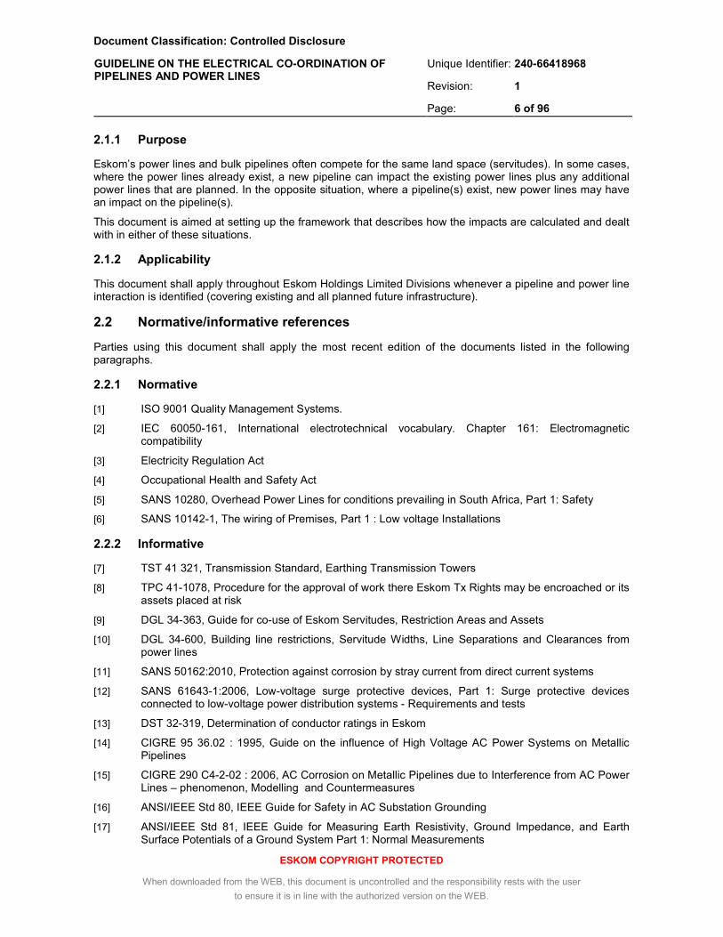
2.1.1 Purpose
Eskom’s power lines and bulk pipelines often compete for the same land space (servitudes). In some cases, where the power lines already exist, a new pipeline can impact the existing power lines plus any additional power lines that are planned. In the opposite situation, where a pipeline(s) exist, new power lines may have an impact on the pipeline(s).
This document is aimed at setting up the framework that describes how the impacts are calculated and dealt with in either of these situations.
2.1.2 Applicability
This document shall apply throughout Eskom Holdings Limited Divisions whenever a pipeline and power line interaction is identified (covering existing and all planned future infrastructure).
2.2 Normative/informative references
Parties using this document shall apply the most recent edition of the documents listed in the following paragraphs.
2.2.1 Normative
[1] ISO 9001 Quality Management Systems.
[2] IEC 60050-161, International electrotechnical vocabulary. Chapter 161: Electromagnetic compatibility
[3] Electricity Regulation Act
[4] Occupational Health and Safety Act
[5] SANS 10280, Overhead Power Lines for conditions prevailing in South Africa, Part 1: Safety
[6] SANS 10142-1, The wiring of Premises, Part 1 : Low voltage Installations
2.2.2 Informative
[7] TST 41 321, Transmission Standard, Earthing Transmission Towers
[8] TPC 41-1078, Procedure for the approval of work there Eskom Tx Rights may be encroached or its assets placed at risk
[9] DGL 34-363, Guide for co-use of Eskom Servitudes, Restriction Areas and Assets
[10] DGL 34-600, Building line restrictions, Servitude Widths, Line Separations and Clearances from power lines
[11] SANS 50162:2010, Protection against corrosion by stray current from direct current systems
[12] SANS 61643-1:2006, Low-voltage surge protective devices, Part 1: Surge protective devices connected to low-voltage power distribution systems - Requirements and tests
[13] DST 32-319, Determination of conductor ratings in Eskom
[14] CIGRE 95 36.02 : 1995, Guide on the influence of High Voltage AC Power Systems on Metallic Pipelines
[15] CIGRE 290 C4-2-02 : 2006, AC Corrosion on Metallic Pipelines due to Interference from AC Power Lines – phenomenon, Modelling and Countermeasures
[16] ANSI/IEEE Std 80, IEEE Guide for Safety in AC Substation Grounding
[17] ANSI/IEEE Std 81, IEEE Guide for Measuring Earth Resistivity, Ground Impedance, and Earth Surface Potentials of a Ground System Part 1: Normal Measurements
Document Classification: Controlled Disclosure
Unique Identifier: 240-66418968
Revision: 1
GUIDELINE ON THE ELECTRICAL CO-ORDINATION OF PIPELINES AND POWER LINES
Page: 7 of 96
ESKOM COPYRIGHT PROTECTED
When downloaded from the WEB, this document is uncontrolled and the responsibility rests with the user
to ensure it is in line with the authorized version on the WEB.
[18] IEC Std. 60479-1: Effects of current on human beings and livestock, Part 1- General aspects
[19] SANS 10199:2004, The design and installation of earth electrodes
[20] NRS084-2:2003: Electricity Supply – Quality of Supply Part 2: Voltage characteristics, compatibility levels, limits and assessment methods
[21] CAN/CSA-C22.3 No. 6-M91 : R2003, Principles and practices of electrical coordination between pipelines and electric supply lines
[22] AS/NZS 4853 : 2011, Electrical hazards on metallic pipelines
[23] prEN 15280, Evaluation of a.c. corrosion likelihood of buried pipelines applicable to cathodically protected pipelines”
[24] prEN 50443: 2009, Effects of electromagnetic interference on pipelines caused by high voltage a.c. railway systems and/or high voltage a.c. power supply systems
[25] NACE Standard RP0177: 2000, Mitigation of Alternating Current and Lightning Effects on Metallic Structures and Cathodic Protection Systems
[26] NACE Internal Publication 35110: 2010: AC Corrosion State-of-the-Art: Corrosion Rate, Mechanism, and Mitigation Requirements
[27] VON BAECKMANN W., SCHWENK W. et al, 1997, Handbook of Cathodic Corrosion Protection, 3rd Edition, Gulf Professional Publishing
[28] FRAZIER, M.J., 2001, Predicting Pipeline Damage from Powerline Faults, NACE Corrosion 2001, Paper No. 1595
[29] CEA Report 239 T817, 1994, Powerline Ground Fault Effects on Pipelines, Prepared by Powertech Labs Inc.
[30] ITU-T Directives, R2005, Directives concerning the protection of telecommunication lines against harmful effects from electric power and electrified railway lines, Volume II – Calculating induced voltages and currents in practical cases
[31] ITU-T Rec K68: 2006, Management of electromagnetic interference on telecommunication systems due to power systems
[32] SEALY-FISHER, V., WEBB N., 1999, Cahora Basa Power Line Interference Study, Technical Bulletin No. 12, SAECC/4/1
2.3 Definitions
2.3.1 General
For the purposes of this guideline, the terms, definitions and abbreviations given in IEC 60050-161 and the following apply:
Definition Description
anode ground bed an installation of conductors below the surface by which direct current is discharged into the earth in an impressed current cathodic protection system
appurtenance that which is connected to a pipeline, e.g. a valve in a pipeline
auto-reclosure action of the power line protection whereby the line is automatically re-energised one or more times after tripping
balanced current conditions
exist when the phasor sum of the phase currents in a three phase system equals zero
bond a low impedance connection designed to maintain a common electric potential

Document Classification: Controlled Disclosure
Unique Identifier: 240-66418968
Revision: 1
GUIDELINE ON THE ELECTRICAL CO-ORDINATION OF PIPELINES AND POWER LINES
Page: 8 of 96
ESKOM COPYRIGHT PROTECTED
When downloaded from the WEB, this document is uncontrolled and the responsibility rests with the user
to ensure it is in line with the authorized version on the WEB.
Definition Description
coating stress the difference in voltage potential between the pipeline wall and the surrounding soil at a given location
counterpoise a conductor or system of conductors below ground, connected to the footings of power line towers
d.c. decoupling device a device used in electrical circuits that allows the flow of a.c. in both directions and prevents or substantially inhibits the flow of d.c.
d.c. potential shift a potential developed between a metallic structure and the surrounding earth as a result of stray d.c. currents in the earth, which can result in electrolytic corrosion of the metallic structure
dielectric breakdown potential
a voltage potential in excess of the rated voltage that causes the destruction of the coating or other insulating material
discharge current current that will flow if the conductor with induced voltage is connected to the earth via a zero impedance bond
dead front a type of construction in which the energized components are recessed or covered to preclude the possibility of accidental contact
earth potential rise the product of a earth electrode impedance, referenced to remote earth, and the current that flows through that electrode impedance
earth resistivity measure of the electrical resistance of a unit volume of soil
NOTE The commonly used unit is the ohm-meter, [Ωm] which refers to the impedance measured between opposite faces of a cubic meter of soil.
galvanic corrosion cell corrosion caused by dissimilar metals in an electrolyte
gradient control wire one or two ribbons installed adjacent to and connected to a pipeline in order to reduce the pipeline coating stress
gradient control mat a system of bare conductors or ribbon on or below the earth’s surface, so designed as to provide an area of equal potential within the range of step distances
impressed current cathodic protection
a system whereby the cathodic protection current is applied using a d.c. rectifier, connected between the protected item and an anode ground bed
remote earth a location on earth that is far enough from the affecting structure that the soil potential gradients associated with the currents entering the earth from the affecting structure are insignificant
residual current (or zero sequence current)
Electrical current, that is equal to the phasor sum of the phase currents, which returns through the earthing system of the power network
NOTE When balanced current conditions exist, the residual current equals zero
ribbon a bare zinc or magnesium profiled conductor, specifically designed for gradient control
right (or right-of-way) means the right to traverse or occupy land and includes inter alia services, surface right permits, way leaves, exercised options, licences and permissions to occupy
sacrificial anode an anode that is attached to a metal object subject to electrolysis and is decomposed instead of the object
Document Classification: Controlled Disclosure
Unique Identifier: 240-66418968
Revision: 1
GUIDELINE ON THE ELECTRICAL CO-ORDINATION OF PIPELINES AND POWER LINES
Page: 9 of 96
ESKOM COPYRIGHT PROTECTED
When downloaded from the WEB, this document is uncontrolled and the responsibility rests with the user
to ensure it is in line with the authorized version on the WEB.
Definition Description
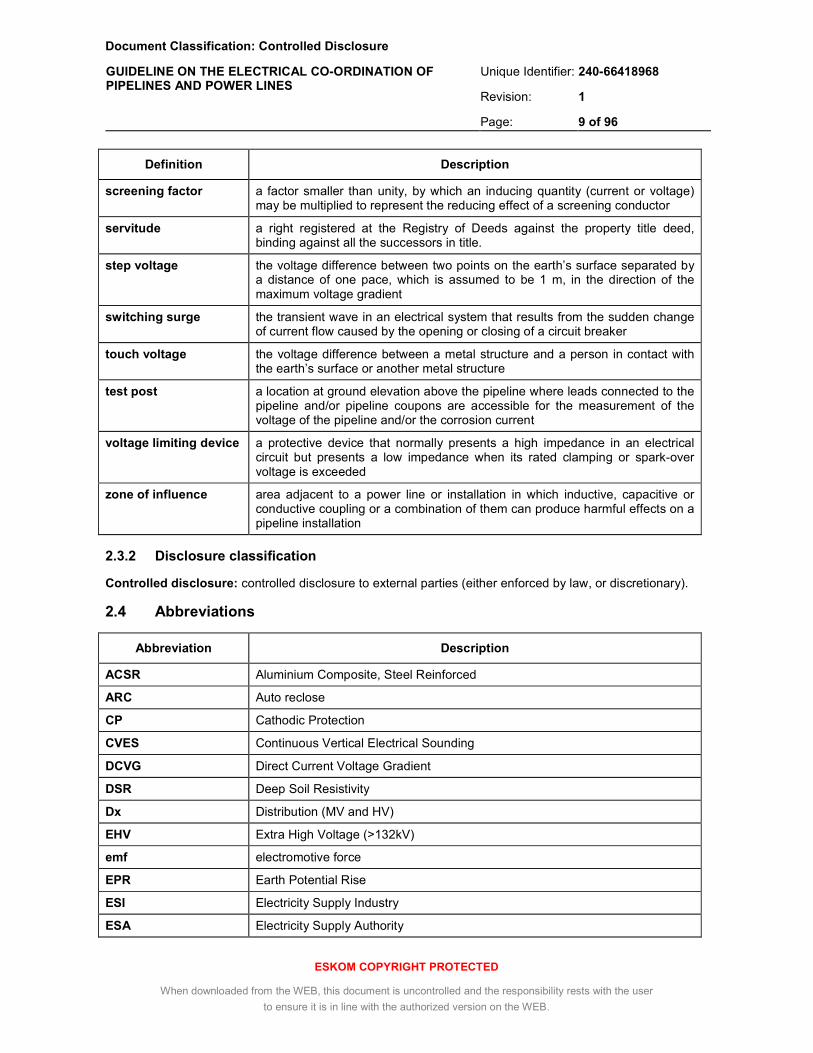
screening factor a factor smaller than unity, by which an inducing quantity (current or voltage) may be multiplied to represent the reducing effect of a screening conductor
servitude a right registered at the Registry of Deeds against the property title deed, binding against all the successors in title.
step voltage the voltage difference between two points on the earth’s surface separated by a distance of one pace, which is assumed to be 1 m, in the direction of the maximum voltage gradient
switching surge the transient wave in an electrical system that results from the sudden change of current flow caused by the opening or closing of a circuit breaker
touch voltage the voltage difference between a metal structure and a person in contact with the earth’s surface or another metal structure
test post a location at ground elevation above the pipeline where leads connected to the pipeline and/or pipeline coupons are accessible for the measurement of the voltage of the pipeline and/or the corrosion current
voltage limiting device a protective device that normally presents a high impedance in an electrical circuit but presents a low impedance when its rated clamping or spark-over voltage is exceeded
zone of influence area adjacent to a power line or installation in which inductive, capacitive or conductive coupling or a combination of them can produce harmful effects on a pipeline installation
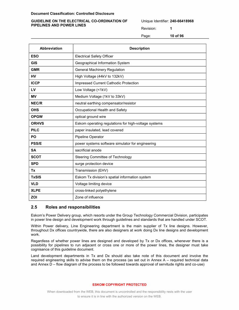
2.3.2 Disclosure classification
Controlled disclosure: controlled disclosure to external parties (either enforced by law, or discretionary).
2.4 Abbreviations
Abbreviation Description
ACSR Aluminium Composite, Steel Reinforced
ARC Auto reclose
CP Cathodic Protection
CVES Continuous Vertical Electrical Sounding
DCVG Direct Current Voltage Gradient
DSR Deep Soil Resistivity
Dx Distribution (MV and HV)
EHV Extra High Voltage (>132kV)
emf electromotive force
EPR Earth Potential Rise
ESI Electricity Supply Industry
ESA Electricity Supply Authority
Document Classification: Controlled Disclosure
Unique Identifier: 240-66418968
Revision: 1
GUIDELINE ON THE ELECTRICAL CO-ORDINATION OF PIPELINES AND POWER LINES
Page: 10 of 96
ESKOM COPYRIGHT PROTECTED
When downloaded from the WEB, this document is uncontrolled and the responsibility rests with the user
to ensure it is in line with the authorized version on the WEB.
Abbreviation Description
ESO Electrical Safety Officer
GIS Geographical Information System
GMR General Machinery Regulation
HV High Voltage (44kV to 132kV)
ICCP Impressed Current Cathodic Protection
LV Low Voltage (<1kV)
MV Medium Voltage (1kV to 33kV)
NEC/R neutral earthing compensator/resistor
OHS Occupational Health and Safety
OPGW optical ground wire
ORHVS Eskom operating regulations for high-voltage systems
PILC paper insulated, lead covered
PO Pipeline Operator
PSS/E power systems software simulator for engineering
SA sacrificial anode
SCOT Steering Committee of Technology
SPD surge protection device
Tx Transmission (EHV)
TxSIS Eskom Tx division’s spatial information system
VLD Voltage limiting device
XLPE cross-linked polyethylene
ZOI Zone of influence
2.5 Roles and responsibilities
Eskom’s Power Delivery group, which resorts under the Group Technology Commercial Division, participates in power line design and development work through guidelines and standards that are handled under SCOT.
Within Power delivery, Line Engineering department is the main supplier of Tx line designs. However, throughout Dx offices countrywide, there are also designers at work doing Dx line designs and development work.
Regardless of whether power lines are designed and developed by Tx or Dx offices, whenever there is a possibility for pipelines to run adjacent or cross one or more of the power lines, the designer must take cognisance of this guideline document.
Land development departments in Tx and Dx should also take note of this document and involve the required engineering skills to advise them on the process (as set out in Annex A – required technical data and Annex D – flow diagram of the process to be followed towards approval of servitude rights and co-use)

Document Classification: Controlled Disclosure
Unique Identifier: 240-66418968
Revision: 1
GUIDELINE ON THE ELECTRICAL CO-ORDINATION OF PIPELINES AND POWER LINES
Page: 11 of 96
ESKOM COPYRIGHT PROTECTED
When downloaded from the WEB, this document is uncontrolled and the responsibility rests with the user
to ensure it is in line with the authorized version on the WEB.
2.6 Process for monitoring
The electrical working group in the Overhead Lines study committee of SCOT will monitor this document and others that are related to power line design and operation. It will take place either under a working group or a care group depending in the needs identified. The SCOT focus is both on technical issues as well as operational issues that may require modifications or updates. Advances in pipe coatings and CP systems need to be monitored continuously to ensure that the technical impacts remain acceptable.
The pipeline industry of South Africa as well as Eskom is keen to support the continued development of this document into a national standard through the NRS mechanisms.
Through the formulation of this document, with inputs and interaction by the pipeline owners, Eskom has set the benchmark for what would be required from a power lines point of view when power lines and pipelines interact.
The onus is still on the pipeline owners to agree on their requirements should a power line have an impact on already installed and operational pipelines.
2.7 Related/supporting documents
Not applicable.
3. The Electrical Coordination of Pipelines and Power Lines
3.1 Statutory and Utility Requirements
3.1.1 Applicable legislation
When a new electrical transmission or distribution scheme or extension to a scheme is considered in the vicinity of an existing pipeline, or when a new pipeline or extension of an existing pipeline is considered in the vicinity of an electricity transmission or distribution scheme, the following legislation is applicable in South Africa:
a) the OHS Act, 1993 (Act No. 85 of 1993) and its accompanying regulations, notably the Electrical Machinery Regulations, 2011 (GNR.250 published in Government Gazette 34154 of 25 March 2011),
b) the Electricity Regulation Act 4 of 2006.
The OHS Act also has specific regulations for gas and petroleum pipelines related to the dangers posed by the transported medium (the Major Hazard Installation Regulations, section 43 of Act No 85), which are outside the scope of this document.
3.1.2 Relevant statutory requirements
Relevant requirements, in the context of this guideline, from the legislation listed in 3.1.1 stipulate the following:
a) In terms of section 8(1) of the OHS Act, POs and ESAs are obliged to provide and maintain safe working environments which include working environments where pipelines or works are under or in the vicinity of power lines.
b) In terms of the Electricity Regulation Act (Section 25), in the event of civil proceedings arising from damage or injury caused by induction, leakage or any other means of unwanted transmission of electricity, the ESA will be presumed to have been negligent unless it can prove otherwise.
Document Classification: Controlled Disclosure
Unique Identifier: 240-66418968
Revision: 1
GUIDELINE ON THE ELECTRICAL CO-ORDINATION OF PIPELINES AND POWER LINES
Page: 12 of 96
ESKOM COPYRIGHT PROTECTED
When downloaded from the WEB, this document is uncontrolled and the responsibility rests with the user
to ensure it is in line with the authorized version on the WEB.
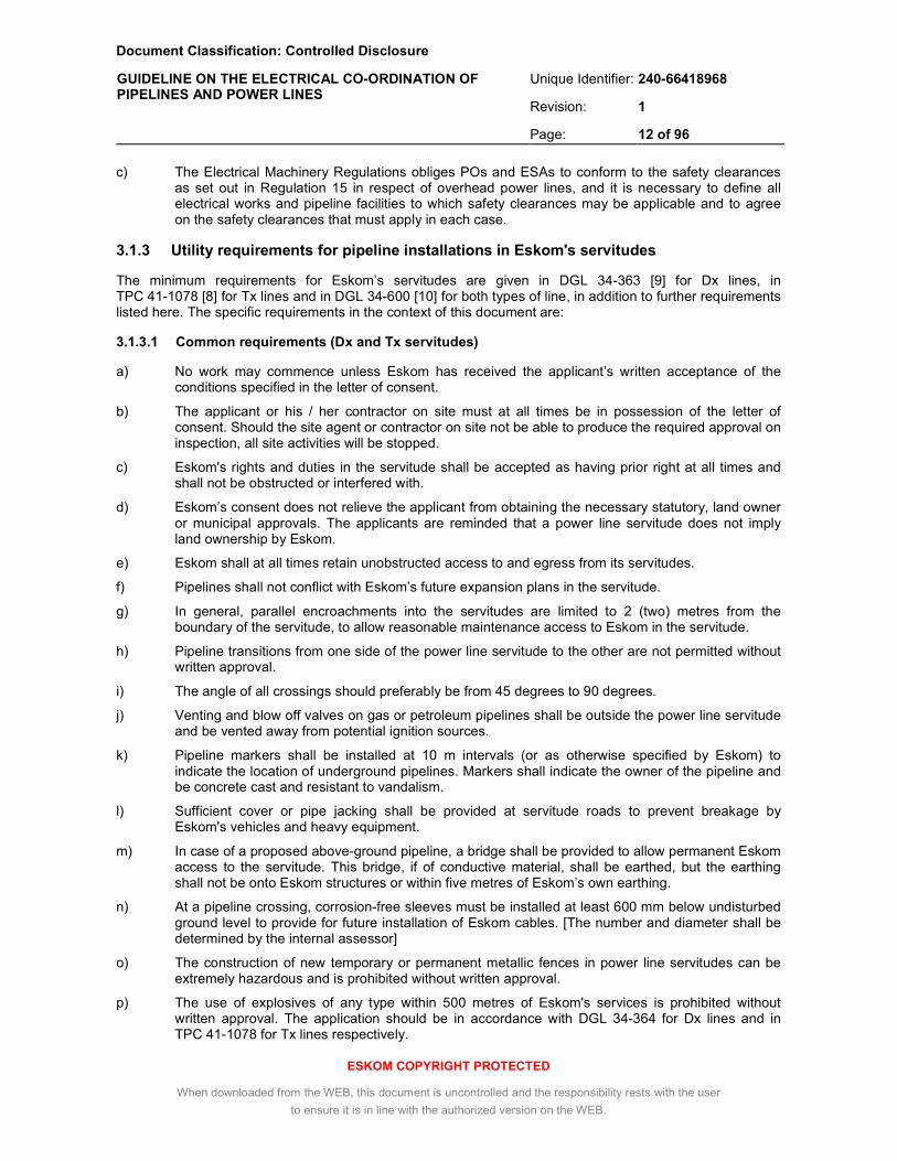
c) The Electrical Machinery Regulations obliges POs and ESAs to conform to the safety clearances as set out in Regulation 15 in respect of overhead power lines, and it is necessary to define all electrical works and pipeline facilities to which safety clearances may be applicable and to agree on the safety clearances that must apply in each case.
3.1.3 Utility requirements for pipeline installations in Eskom's servitudes
The minimum requirements for Eskom’s servitudes are given in DGL 34-363 [9] for Dx lines, in TPC 41-1078 [8] for Tx lines and in DGL 34-600 [10] for both types of line, in addition to further requirements listed here. The specific requirements in the context of this document are:
3.1.3.1 Common requirements (Dx and Tx servitudes)
a) No work may commence unless Eskom has received the applicant’s written acceptance of the conditions specified in the letter of consent.
b) The applicant or his / her contractor on site must at all times be in possession of the letter of consent. Should the site agent or contractor on site not be able to produce the required approval on inspection, all site activities will be stopped.
c) Eskom's rights and duties in the servitude shall be accepted as having prior right at all times and shall not be obstructed or interfered with.
d) Eskom’s consent does not relieve the applicant from obtaining the necessary statutory, land owner or municipal approvals. The applicants are reminded that a power line servitude does not imply land ownership by Eskom.
e) Eskom shall at all times retain unobstructed access to and egress from its servitudes.
f) Pipelines shall not conflict with Eskom’s future expansion plans in the servitude.
g) In general, parallel encroachments into the servitudes are limited to 2 (two) metres from the boundary of the servitude, to allow reasonable maintenance access to Eskom in the servitude.
h) Pipeline transitions from one side of the power line servitude to the other are not permitted without written approval.
i) The angle of all crossings should preferably be from 45 degrees to 90 degrees.
j) Venting and blow off valves on gas or petroleum pipelines shall be outside the power line servitude and be vented away from potential ignition sources.
k) Pipeline markers shall be installed at 10 m intervals (or as otherwise specified by Eskom) to indicate the location of underground pipelines. Markers shall indicate the owner of the pipeline and be concrete cast and resistant to vandalism.
l) Sufficient cover or pipe jacking shall be provided at servitude roads to prevent breakage by Eskom's vehicles and heavy equipment.
m) In case of a proposed above-ground pipeline, a bridge shall be provided to allow permanent Eskom access to the servitude. This bridge, if of conductive material, shall be earthed, but the earthing shall not be onto Eskom structures or within five metres of Eskom’s own earthing.
n) At a pipeline crossing, corrosion-free sleeves must be installed at least 600 mm below undisturbed ground level to provide for future installation of Eskom cables. [The number and diameter shall be determined by the internal assessor]
o) The construction of new temporary or permanent metallic fences in power line servitudes can be extremely hazardous and is prohibited without written approval.
p) The use of explosives of any type within 500 metres of Eskom's services is prohibited without written approval. The application should be in accordance with DGL 34-364 for Dx lines and in TPC 41-1078 for Tx lines respectively.

Document Classification: Controlled Disclosure
Unique Identifier: 240-66418968
Revision: 1
GUIDELINE ON THE ELECTRICAL CO-ORDINATION OF PIPELINES AND POWER LINES
Page: 13 of 96
ESKOM COPYRIGHT PROTECTED
When downloaded from the WEB, this document is uncontrolled and the responsibility rests with the user
to ensure it is in line with the authorized version on the WEB.
q) The pipeline voltages as a result of electrical coupling during normal and fault conditions on the power line(s) shall not exceed the respective values indicated in 3.3.3 and 3.3.4.
r) The stray d.c. voltages near power line structures as a result of ICCP systems shall not exceed the values indicated in 3.3.8.
s) Test posts shall use dead front construction in accordance with NACE RP0177.
t) It is required of applicants to familiarize themselves with all safety hazards related to Electrical plant. Safe working procedures shall be applied during construction (see 3.8).
u) The clearances between Eskom’s live electrical equipment and the proposed construction work shall be observed as stipulated by Regulation 15 of the Electrical Machinery Regulations of the Occupational Health and Safety Act, 1993 (Act 85 of 1993) (see 3.8.2, table 15).
v) No mechanical equipment, including mechanical excavators or high lifting machinery, shall be used in the vicinity of Eskom’s apparatus and/or services, without prior written permission having been granted by Eskom. If such permission is granted the applicant must give at least seven working days prior notice of the commencement of work. This allows time for arrangements to be made for supervision and/or precautionary instructions to be issued. The internal assessor must provide the applicant with the details of an Eskom person to be contacted in this regard.
w) Changes in ground level may not infringe statutory ground to conductor clearances or statutory visibility clearances. After any changes in ground level, the surface shall be rehabilitated and stabilised so as to prevent erosion. The measures taken shall be to Eskom's requirements.
x) Electrical installations on the pipeline for example the cathodic protection system, protection devices and electrical wiring shall comply with the applicable provisions in SANS 10142, and inspected and certified by a qualified installation electrician (or master installation electrician in case of hazardous locations).
y) Eskom shall not be liable for the death of or injury to any person or for the loss of or damage to any property whether as a result of the encroachment or of the use of the servitude area by the applicant, his/her agent, contractors, employees, successors in title, and assignees.
z) The PO shall indemnify Eskom in writing against loss, claims or damages including claims pertaining to consequential damages by third parties and whether as a result of damage to or interruption of service or interference with Eskom's services or apparatus or otherwise. Eskom shall not be held responsible for damage to the applicant’s equipment.
aa) The PO's construction manager shall report any damage to Eskom's property, private property or public facilities, and the PO agrees to pay all expenses incurred in connection with the repair of such damages.
3.1.3.2 Further requirements for Tx servitudes
a) No excavations are permitted within 20 m of above-ground power line structures including towers, guy wires, anchors and other attachments. Exceptions may be permitted, subject to a case by case evaluation of the foundation and the soil conditions.
b) No above-ground buildings are permitted within the following distances of a Tx power line, measured from the centreline of the power line, as a function of the voltage level:
i. 220 kV - 275 kV (delta): 18 m
ii. 220 kV - 275 kV (horizontal): 23.5 m
iii. 400 kV (self-supporting): 23.5 m
iv. 400 kV (stayed) 27.5 m
v. 765 kV 40 m

Document Classification: Controlled Disclosure
Unique Identifier: 240-66418968
Revision: 1
GUIDELINE ON THE ELECTRICAL CO-ORDINATION OF PIPELINES AND POWER LINES
Page: 14 of 96
ESKOM COPYRIGHT PROTECTED
When downloaded from the WEB, this document is uncontrolled and the responsibility rests with the user
to ensure it is in line with the authorized version on the WEB.
3.1.3.3 Further requirements for Dx servitudes
a) No excavations are permitted within 6 m of above-ground power line structures including towers, guy wires, anchors and other attachments. Where this cannot be achieved, or where there is a risk of a ruptured pipe eroding a tower foundation, the pipe section is to be placed in concrete.
b) No above-ground buildings are permitted within the following distances of a Dx power line, measured from the centreline of the power line, as a function of the voltage level:
i. all voltages below 22 kV: 9 m
ii. 22 kV: 9 m
iii. 33 kV – 88 kV: 11 m
iv. 132 kV: 18 m
3.2 Co-ordination and Management Procedure
3.2.1 Co-ordination
Good co-operation between Eskom and the POs is essential to ensure that all the co-ordination requirements are met. Both parties must ensure that adequate specialist skills are available to them, to enable professional assessment of the methods and measures used to prevent conditions which may be dangerous to employees concerned or to the public, or which may damage or degrade the pipeline or power line works.
Co-ordination and service meetings between the specialists of the POs and Eskom should complement the formal meeting mentioned in 3.2.2 o), particularly in the case of long or complex exposures.
When the servitude under consideration contains both Dx and Tx power lines, the co-operation must extend to both Eskom’s Dx and Tx departments. It is emphasised that since the respective Land & Rights issues are under the management of separate offices, any approval granted by Eskom Dx does not automatically imply Eskom Tx approval, or vice versa.
Further liaison between the specialists of the respective parties is recommended through the forum of the SAECC. The preferred arrangement is that an SAECC working group is established with the responsibility of sharing information and developing skills in respect of electrical coupling between power lines and pipelines, including the training of safety officers.
3.2.2 Procedure for obtaining approval for new installations
When a new pipeline is planned that involves any construction in Eskom’s servitudes, the following steps are required towards approval of the right of way (flow chart provided in Annex D):
a) the PO’s right of way application (annex A of TPC41-1078 for Tx servitudes, or annex A of DLG 34-363 for Dx servitudes, or both in case of combined Tx/Dx servitudes) along with the pipeline design details according to checklist A.1 of Annex A, is completed and submitted to Eskom’s regional office for attention of Land and Rights, at least six months prior to planned commencement of the project,
b) the application is checked for completeness, registered on the system (Investigations_ logbook.xls) and assigned a Senior Advisor : Investigations and Audit (Tx) or to an Internal Assessor (Dx), according to the procedures described respectively in TP C41-1078 and DLG 34-363,
c) the Senior Advisor or Internal Assessor examines the application and identifies the affected Tx and Dx power lines or cables on TxSIS GIS, and captures this information using the template A.2 in Annex A,
Document Classification: Controlled Disclosure
Unique Identifier: 240-66418968
Revision: 1
GUIDELINE ON THE ELECTRICAL CO-ORDINATION OF PIPELINES AND POWER LINES
Page: 15 of 96
ESKOM COPYRIGHT PROTECTED
When downloaded from the WEB, this document is uncontrolled and the responsibility rests with the user
to ensure it is in line with the authorized version on the WEB.
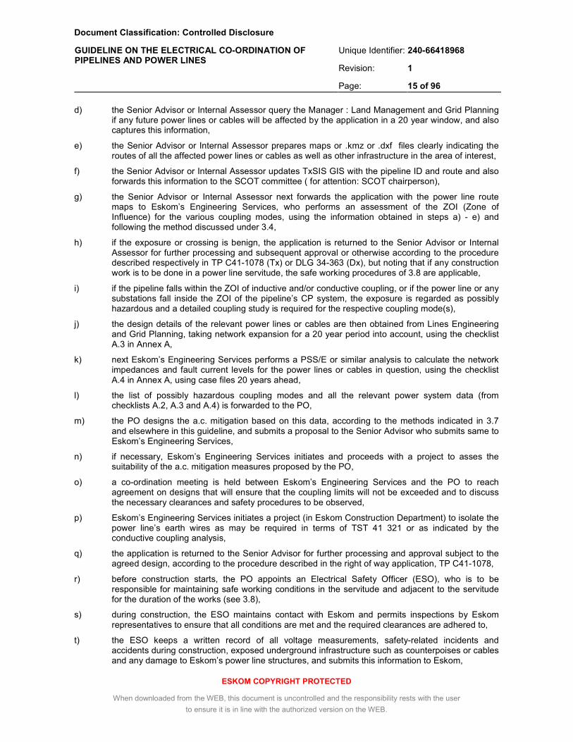
d) the Senior Advisor or Internal Assessor query the Manager : Land Management and Grid Planning if any future power lines or cables will be affected by the application in a 20 year window, and also captures this information,
e) the Senior Advisor or Internal Assessor prepares maps or .kmz or .dxf files clearly indicating the routes of all the affected power lines or cables as well as other infrastructure in the area of interest,
f) the Senior Advisor or Internal Assessor updates TxSIS GIS with the pipeline ID and route and also forwards this information to the SCOT committee ( for attention: SCOT chairperson),
g) the Senior Advisor or Internal Assessor next forwards the application with the power line route maps to Eskom’s Engineering Services, who performs an assessment of the ZOI (Zone of Influence) for the various coupling modes, using the information obtained in steps a) - e) and following the method discussed under 3.4,
h) if the exposure or crossing is benign, the application is returned to the Senior Advisor or Internal Assessor for further processing and subsequent approval or otherwise according to the procedure described respectively in TP C41-1078 (Tx) or DLG 34-363 (Dx), but noting that if any construction work is to be done in a power line servitude, the safe working procedures of 3.8 are applicable,
i) if the pipeline falls within the ZOI of inductive and/or conductive coupling, or if the power line or any substations fall inside the ZOI of the pipeline’s CP system, the exposure is regarded as possibly hazardous and a detailed coupling study is required for the respective coupling mode(s),
j) the design details of the relevant power lines or cables are then obtained from Lines Engineering and Grid Planning, taking network expansion for a 20 year period into account, using the checklist A.3 in Annex A,
k) next Eskom’s Engineering Services performs a PSS/E or similar analysis to calculate the network impedances and fault current levels for the power lines or cables in question, using the checklist A.4 in Annex A, using case files 20 years ahead,
l) the list of possibly hazardous coupling modes and all the relevant power system data (from checklists A.2, A.3 and A.4) is forwarded to the PO,
m) the PO designs the a.c. mitigation based on this data, according to the methods indicated in 3.7 and elsewhere in this guideline, and submits a proposal to the Senior Advisor who submits same to Eskom’s Engineering Services,
n) if necessary, Eskom’s Engineering Services initiates and proceeds with a project to asses the suitability of the a.c. mitigation measures proposed by the PO,
o) a co-ordination meeting is held between Eskom’s Engineering Services and the PO to reach agreement on designs that will ensure that the coupling limits will not be exceeded and to discuss the necessary clearances and safety procedures to be observed,
p) Eskom’s Engineering Services initiates a project (in Eskom Construction Department) to isolate the power line’s earth wires as may be required in terms of TST 41 321 or as indicated by the conductive coupling analysis,
q) the application is returned to the Senior Advisor for further processing and approval subject to the agreed design, according to the procedure described in the right of way application, TP C41-1078,
r) before construction starts, the PO appoints an Electrical Safety Officer (ESO), who is to be responsible for maintaining safe working conditions in the servitude and adjacent to the servitude for the duration of the works (see 3.8),
s) during construction, the ESO maintains contact with Eskom and permits inspections by Eskom representatives to ensure that all conditions are met and the required clearances are adhered to,
t) the ESO keeps a written record of all voltage measurements, safety-related incidents and accidents during construction, exposed underground infrastructure such as counterpoises or cables and any damage to Eskom’s power line structures, and submits this information to Eskom,
Document Classification: Controlled Disclosure
Unique Identifier: 240-66418968
Revision: 1
GUIDELINE ON THE ELECTRICAL CO-ORDINATION OF PIPELINES AND POWER LINES
Page: 16 of 96
ESKOM COPYRIGHT PROTECTED
When downloaded from the WEB, this document is uncontrolled and the responsibility rests with the user
to ensure it is in line with the authorized version on the WEB.
u) upon completion of the pipeline works and surface restoration, an Eskom representative performs an inspection of all a.c. mitigation measures, the pipeline markers, any damage to power line structures and the quality of the surface restoration (see 3.9 and checklist in Annex E),
v) if so agreed upon by the parties, measurements are performed at this stage to determine if the d.c. potential shift at selected pylons or earth mats, resulting from switching the CP system on and off, is within the required limits,
w) providing the outcome of steps u) and v) is positive, the final approval for the commissioning of the installation is granted (see 3.9).
When a new power line or installation is planned in an existing pipeline servitude, essentially the same procedure is followed; in this case initiated by Eskom, and subsequently inspected and approved by the PO.
3.2.3 Cost of mitigation, protection and maintenance measures
In the case of new works, the cost of the agreed upon measures shall be borne by the party initiating the new installation. This includes the cost of any modification required to the existing works belonging to the owner of the servitude. In the case of a pipeline application in existing power line servitude this would include, for example, the cost of isolating the power line’s earth wires. In the case of a new power line influencing an existing pipeline, this would include the cost of all the a.c. mitigation measures required.
The owner of the servitude shall further be entitled to recuperate from the applicant the cost of the assessment described in 3.4, the cost of the modelling exercise described in 3.6, the cost of inspections and if damage occurred, the cost of any repairs to the existing works.
In the case of induction problems arising on existing installations, the cost shall be borne by the party on whose installation the protection or mitigation measures are implemented.
In the case of a benign co-location becoming hazardous as a result of a power line upgrade or an increase in the level of cathodic protection used on the pipeline, the cost shall be borne by the party who was granted permission for co-use of the servitude by the owner.
In the case of there being no registered servitude owner yet at the time that the co-location is planned, each party shall be responsible for the cost of the measures on their own equipment, whilst the cost of the assessment and modelling exercise shall be equally shared.
In all cases, each party is responsible for the cost of maintaining the integrity of their own equipment including attachments, insulation and earthing.
3.3 Coupling Limits
3.3.1 Origin of safety limits
Safe limits of step and touch voltages are based on the maximum body current that can be endured by a person without affecting muscular control or causing ventricular fibrillation. The standards IEEE 80 and IEC 60479-1 provide safety criteria based on the fibrillation current derived from empirical studies.
The safety limits used here for fault conditions are adopted from the IEC standard, which is based on more recent research. The fibrillation current curve C1 is used, representing 95% of the population (see Fig 20 in IEC 60479-1).
For pipeline sections exposed to the general public, the worst-case condition considered is where both hands are in contact with the pipeline and both feet in contact with the earth. No reduction factor for footwear is applied, as some pipelines may be accessible to bare-footed children, for example.
For pipeline sections accessible only by authorised personnel, the worst condition considered is likewise where both hands are in contact with the pipeline and both feet with the earth, but footwear is accounted for with a conservative resistance of 1000 ohm.
Document Classification: Controlled Disclosure
Unique Identifier: 240-66418968
Revision: 1
GUIDELINE ON THE ELECTRICAL CO-ORDINATION OF PIPELINES AND POWER LINES
Page: 17 of 96
ESKOM COPYRIGHT PROTECTED
When downloaded from the WEB, this document is uncontrolled and the responsibility rests with the user
to ensure it is in line with the authorized version on the WEB.
The safety limits for steady state conditions are based on a 10 mA r.m.s. body current, which is the maximum safe let-go current for adult men. For pipelines or sections of the pipeline exposed to the public including children, the maximum let-go current is reduced to 5 mA r.m.s. The hand-to-hand or hand-to-foot resistance is considered to be equal to or higher than 1 500 ohm, a reasonably safe assumption when touch voltages remain within the limits required (see Table 1, IEC 60479-1).
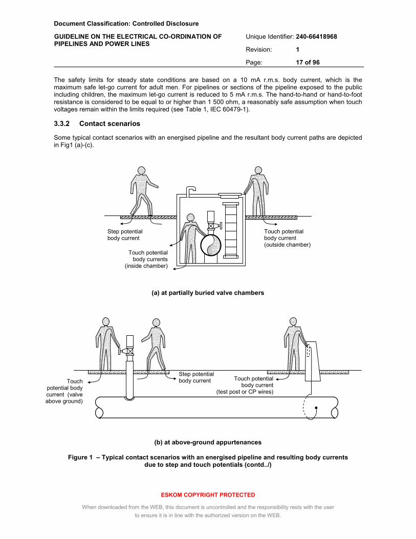
3.3.2 Contact scenarios
Some typical contact scenarios with an energised pipeline and the resultant body current paths are depicted in Fig1 (a)-(c).
(a) at partially buried valve chambers
(b) at above-ground appurtenances
Figure 1 – Typical contact scenarios with an energised pipeline and resulting body currents due to step and touch potentials (contd../)
Step potential body current
Touch potential body currents
(inside chamber)
Touch potential body current (valve above ground)
Step potential body current Touch potential
body current (test post or CP wires)
Touch potential body current (outside chamber)

Document Classification: Controlled Disclosure
Unique Identifier: 240-66418968
Revision: 1
GUIDELINE ON THE ELECTRICAL CO-ORDINATION OF PIPELINES AND POWER LINES
Page: 18 of 96
ESKOM COPYRIGHT PROTECTED
When downloaded from the WEB, this document is uncontrolled and the responsibility rests with the user
to ensure it is in line with the authorized version on the WEB.
(c) across insulating flanges and to separate earths
Figure 1 (contd.) – Typical contact scenarios with an energised pipeline and resulting body currents due to step and touch potentials
Inside valve chambers, direct contact with the pipeline is possible, and the current path can be through the wall or the floor (see Fig 1 (a)). Outside the valve chambers, indirect touch potentials can occur through the chamber roof and walls.
Step potentials can result from the voltage gradient around the chamber or the above-ground appurtenance (see Fig 1 (b)).
In the case of pipelines installed on plinths above ground, direct touch potentials are possible to local earths, to foreign earths or across insulating flanges (see Fig 1 (c)).
3.3.3 Limits relating to danger during fault conditions
In the event of an earth fault on the power line(s), the touch and step voltages with respect to local earth at any accessible section of the pipeline shall not exceed the values given in Table 1, for public and occupational exposure respectively.
For most pipelines the occupational exposure limits will be applicable. The public exposure limits are only applicable for above - ground pipelines or appurtenances that are not protected from public access.
Touch potential body current
(insulating flange)
Touch potential body current
(foreign earth, e.g. a fence)

Document Classification: Controlled Disclosure
Unique Identifier: 240-66418968
Revision: 1
GUIDELINE ON THE ELECTRICAL CO-ORDINATION OF PIPELINES AND POWER LINES
Page: 19 of 96
ESKOM COPYRIGHT PROTECTED
When downloaded from the WEB, this document is uncontrolled and the responsibility rests with the user
to ensure it is in line with the authorized version on the WEB.
Table 1: Limiting values for induced pipeline touch and step voltage during faults
Maximum touch (T) and step (S) voltages for different surface layers:
[V r.m.s.]
Exposure Fault duration1)
, t
[s]
Natural soil or concrete slab
2)
15-20 cm crushed stone layer
2)
15-20 cm asphalt layer
2)
t ≤ 0,1 170 (T)
220 (S)
570 (T)
1 800 (S)
4 300 (T)
> 5 000 (S)
0,1 < t ≤ 0,2 160 (T)
200 (S)
510 (T)
1 600 (S)
3 800 (T)
> 5 000 (S)
0,2 < t ≤ 0,5 60 (T)
70 (S)
170 (T)
510 (S)
1 200 (T)
4 600 (S)
0,5 < t ≤ 1,0 34 (T)
40 (S)
90 (T)
260 (S)
600 (T)
2 300 (S)
General public
1,0 < t ≤ 20 26 (T)
32 (S)
70 (T)
200 (S)
450 (T)
1 700 (S)
t ≤ 0,1 340 (T)
900 (S)
820 (T)
2 600 (S)
4 500 (T)
> 5 000 (S)
0,1 < t ≤ 0,2 300 (T)
800 (S)
730 (T)
2 300 (S)
4 000 (T)
> 5 000 (S)
0,2 < t ≤ 0,5 105 (T)
260 (S)
240 (T)
720 (S)
1 250 (T)
4 800 (S)
0,5 < t ≤ 1,0 60 (T)
135 (S)
130 (T)
370 (S)
640 (T)
2 400 (S)
Authorised personnel
1,0 < t ≤ 20 45 (T)
110 (S)
95 (T)
270 (S)
460 (T)
1 800 (S)
Notes:
1) Use the cumulative fault duration of the maximum number of reclosures.
2) Assumed resistivity of natural soil or concrete slab: 30 ohm.m, crushed stone : 1000 ohm.m, asphalt: 10 000 ohm.m; all under wet conditions, ref. IEEE 80.
The benefit of a protective surface layer is evident from Table 1. Asphalt in particular exhibits a very high soil resistivity. Concrete slab (and also soilcrete, i.e. backfill mixed with cement) on the other hand, is a very poor insulator, due do the hygroscopic nature of cement.
The fault duration on Eskom lines of usual construction is given in Table 2. In accordance with IEEE 80, the cumulative fault duration should be applied taking account of the auto-reclosures.

Document Classification: Controlled Disclosure
Unique Identifier: 240-66418968
Revision: 1
GUIDELINE ON THE ELECTRICAL CO-ORDINATION OF PIPELINES AND POWER LINES
Page: 20 of 96
ESKOM COPYRIGHT PROTECTED
When downloaded from the WEB, this document is uncontrolled and the responsibility rests with the user
to ensure it is in line with the authorized version on the WEB.
Table 2: Typical fault duration on Eskom power lines
Voltage level
Maximum fault duration
[s]
Total number of successive
trips 1)
Cumulative fault duration
[s]
Backup protection duration
2)
[s]
11 kV – 33 kV 3) 4.0 5 20 20
44 kV – 132 kV
with teleprotection: 0.1
with stepped-distance protection 4):
0.5
2
with teleprotection: 0.2
with stepped-distance protection 4):
0.5
0.85)
220 kV – 765 kV 0.1 2 0.2 0.85)
Notes:
1) Trips in quick succession with auto-reclose, excluding controlled closure after ARC lock-out 2) Apply backup protection times only for pipelines continuously and frequently exposed to the general public,
e.g. above-ground pipelines in public walkways
3) Eskom’s MV circuits are earthed with NEC/Rs which limit the earth fault current to 360 A 4) This value applies only to the last 20% of the line, which uses Zone 2 protection and does not auto-reclose.
Between 20% and 80% of the line, the fault will be cleared within 0.1 sec by Zone 1 from both ends 5) This applies to Zone 3 protection. High impedance faults (Zfault > 20 ohm) may take 1 sec or longer to clear,
but have a reduced fault current
3.3.4 Limits relating to danger during steady state conditions
During worst case conditions on the power line(s), the touch voltage of the pipeline and its appurtenances shall not exceed:
a) 15 V r.m.s. at pipeline sections exposed only to authorised personnel,
b) 7.5 V r.m.s at pipeline sections exposed to the general public.
Worst case conditions shall take into consideration the emergency load current, the phase current unbalance, effects of multiple circuits and planned expansion or upgrade of the power network.
For most pipelines the 15 V r.m.s. limit will be applicable. The 7.5 V r.m.s. limit is only applicable for above - ground pipelines or appurtenances that are not protected from public access.
The locations on the pipeline where the voltage peaks will most likely occur are discussed in 3.6.9.
3.3.5 Limits relating to damage of pipeline coatings
The maximum permissible pipeline coating voltage stress is dependant on the dielectric strength of the coating material and the method used to cover field joints.
Bitumen can experience glow and arc discharges for coating stress above 1 000 V r.m.s., limiting the maximum permissible value for bitumen-based coatings to about 900 V r.m.s., irrespective of coating thickness.
Polyurethane -, epoxy - and polyethylene - based coatings of normal thickness can tolerate voltages in excess of 10 000 V r.m.s., although the coating stress is generally limited to around 5 000 V r.m.s., to take future deterioration and the effect of field joints into account. For these coatings, the dielectric breakdown strength increases with coating thickness.
The respective value, to be established in consultation with the PO, shall be applied during worst case fault conditions (see 3.6.3.3).

Document Classification: Controlled Disclosure
Unique Identifier: 240-66418968
Revision: 1
GUIDELINE ON THE ELECTRICAL CO-ORDINATION OF PIPELINES AND POWER LINES
Page: 21 of 96
ESKOM COPYRIGHT PROTECTED
When downloaded from the WEB, this document is uncontrolled and the responsibility rests with the user
to ensure it is in line with the authorized version on the WEB.
3.3.6 Limits relating to damage of cathodic protection equipment
The full induced a.c. voltage (i.e. without any localised mitigation) will appear across the CP rectifier during an earth fault. With proper design, this voltage will not exceed the maximum permissible coating stress.
The CP rectifier must hence be capable of withstanding the maximum coating stress voltage (see 3.3.5) for the duration of a fault cleared by the backup protection system (see Table 2).
The full induced steady state a.c. voltage will also appear across the CP rectifier and can be converted to a d.c. voltage, which can increase the ground bed d.c. current. The resultant increase in anode ground bed consumption needs to be taken into account during the ground bed design.
The CP equipment will further be vulnerable to lightning and switching surges through its power supply, in addition to possible transients from nearby d.c. traction systems. For this reason, the transformer and rectifier are equipped with SPDs, typically rated as follows:
• Lightning current rating 8/20 µsec 40 kA
• Lightning impulse clamping voltage (min) 500 V
• Response time 25 ns
Where surge levels are expected to exceed this rating, special precautions are required.
3.3.7 Limits relating to a.c. induced pipeline corrosion
The induced voltage limit to prevent possible a.c. induced corrosion damage at pipeline coating defects has to be decided on by the PO, and is not enforceable by the ESA.
Whilst the study of this phenomenon is ongoing, there is some evidence that for modern coatings in certain soils, a.c. induced corrosion is possible at voltage levels well below the safety limits of 3.3.4. Recommendations in this regard are given in CIGRE TB 290, CEN TS 15280 and NACE 35110. These documents suggest the following voltage and current density limits to significantly reduce a.c. corrosion likelihood, based on the practical experience of European operators:
a) 10 V r.m.s. and 100 A r.m.s./m² where the local soil resistivity exceeds 25 ohm.m
b) 4 V r.m.s. and 40 A r.m.s./m² where the local soil resistivity is less than 25 ohm.m
The current density limits apply to the discharge current at a coating holiday. For a 1 cm² holiday, the current limit is 10 mA and 4 mA for a) and b) respectively. The voltage limits indicated will ensure that the current density limits are not exceeded.
Unlike the safety limit, these limits are intended to be applied at accessible as well as inaccessible sections of the pipeline. Because a.c. corrosion is a long term process however, it is only necessary that these limits are met during normal load conditions and not during short term, emergency load conditions on the inducing power line(s).
3.3.8 Limits relating to d.c. leakage from pipelines and anode ground beds
In terms of earthing standard TST-41-321, all transmission line towers within 800 m of pipelines employing impressed current CP systems must have their earth wires isolated from the towers with suitable insulators, to prevent circulating d.c. currents.
Where it can be shown however by proper measurement and/or modelling that the d.c. potential shift limits indicated in a) or b) below are not exceeded, or if the towers are cathodically protected, this requirement may be waived, in consultation with Eskom.

Document Classification: Controlled Disclosure
Unique Identifier: 240-66418968
Revision: 1
GUIDELINE ON THE ELECTRICAL CO-ORDINATION OF PIPELINES AND POWER LINES
Page: 22 of 96
ESKOM COPYRIGHT PROTECTED
When downloaded from the WEB, this document is uncontrolled and the responsibility rests with the user
to ensure it is in line with the authorized version on the WEB.
a) Leakage from pipelines
With the pipeline at a negative potential, the adjacent soil will assume a negative potential through coating imperfections. Current can then be extracted from any earthed structure such as a power line tower, resulting in anodic interference (corrosion). To limit this effect, the maximum permissible positive d.c. potential shift with respect to the surrounding soil resulting from the CP system is (from Table 1, SANS 50162):
maximum positive d.c. potential shift (resulting from pipeline leakage): 200 mV
This is the limit applicable for a steel structure in a concrete foundation, and includes the IR - drop in the concrete surrounding the structure. It can be evaluated by toggling the CP system on and off whilst measuring the corresponding change in the structure’s d.c. voltage, using a simple voltmeter and a reference electrode inserted into the soil next to the foundation. The maximum rated CP current should be applied to the pipeline during this test.
A 200 mV d.c. potential shift can manifest itself at the tower footing of a power line when the d.c. voltage gradient exceeds 200 mV over the length of a single power line span.
b) Leakage from anode ground beds to towers connected by earth wires
Anode ground beds produce a localised positive d.c. voltage in the adjacent soil, which injects current into nearby earthed structures, resulting in cathodic interference (protection).
Where this current exits the structure and re-enters the soil however, anodic interference (corrosion) occurs. When the power line’s earth wires are directly connected to the towers, this return current is typically shared by a number of towers further away, before returning through the soil to the pipeline and back to the source.
The requirement in this case is that the return currents at these remote towers will not produce a positive d.c. potential shift in excess of 200 mV.
In view of this, post-installation measurements should be performed at all the towers where the current is expected to return to earth, to confirm that the 200 mV limit is met.
Such measurements are required whenever the negative d.c. potential shift at the current entry point exceeds 200 mV, and should be made with the maximum rated current applied to the anode ground bed.
c) Leakage from anode ground beds to isolated towers
When anode ground beds are installed near power line towers (<500 m separation), the surface d.c. gradient across the individual legs or guy wire anchors can be large enough to cause corrosion even on isolated towers. The applicable limit in this case is:
maximum positive d.c. potential shift (resulting from anode ground beds): 200 mV
This d.c. potential shift can manifest when the surface d.c. voltage gradient exceeds 400 mV over the distance between the legs or guy anchors. When this limit is exceeded, the tower has to be protected with sacrificial anodes.
3.4 Assessment of the possible hazardous nature of an exposure
3.4.1 Data gathering
A significant amount of information concerning the pipeline and the power line(s) is required to enable a detailed study of the safety and corrosion aspects that results from the various electrical coupling mechanisms. The required information is covered in the checklists A.1 – A.4 of Annex A.
The step-by-step procedure for obtaining this information is provided in 3.2.2. Various sign-off areas are included in the checklists for each of the contributors to sign off before passing it on to the next step.
Document Classification: Controlled Disclosure
Unique Identifier: 240-66418968
Revision: 1
GUIDELINE ON THE ELECTRICAL CO-ORDINATION OF PIPELINES AND POWER LINES
Page: 23 of 96
ESKOM COPYRIGHT PROTECTED
When downloaded from the WEB, this document is uncontrolled and the responsibility rests with the user
to ensure it is in line with the authorized version on the WEB.
1e110a
pLvi−
ρ⋅=
fpu
max
Ikk
V64v
⋅⋅
⋅=
+
ρ⋅=
1a
12100ln
vL
2i
p
Only the information covered in checklists A.1 and A.2 of Annex A is required to determine the Zones of Influence (ZOIs) for the different coupling mechanisms, as outlined in 3.4.2. If no soil data is provided, a conservative value for deep soil resistivity of 1 000 ohm.m should be used for determining the ZOI for inductive coupling (see 3.4.2.1), or a surface resistivity of 5 000 ohm.m for determining the ZOIs for conductive coupling and d.c. coupling from the CP system (see 3.4.2.2, 3.4.2.4).
When the pipeline is found to be within one of the ZOIs of the power line, the corresponding information of checklists A.3 and A.4 is also required. Measurement of soil resistivity then becomes essential, as outlined in 3.5.
3.4.2 Establishing Zones of Influence
3.4.2.1 ZOI from overhead power lines and cables due to inductive coupling
This ZOI is determined by the distance between the centre of the power line and a parallel pipeline beyond which, the voltage developed on the pipeline cannot exceed a given limit. It is a function of the soil resistivity, the length of the exposure, the earth fault current level, the power system screening factors, the fault duration and the corresponding voltage limit.
For this calculation, the pipeline is assumed to be completely isolated, with no leakage through its coating, and with no earthing or mitigation measures applied.
The zone width ai (applicable on both sides of the power line, see Fig 2) may be established for a specific situation from the equation:
[m] (1)
where:
ρ is the soil resistivity (see 3.4.1), [ohm.m],
Lp is the length of the exposure, projected onto the power line (see Fig 3), [km],
and is a parameter calculated from the following values:
Vmax, the induced voltage limit for an earth fault, from Table 1, [V r.m.s.],
ku, the screening factor due to urban infrastructure, from ITU-T K.68 (see Table 3),
kp, the screening factor due the earth wires or the power cable sheath (see Table 3),
If, the maximum phase-to-earth fault current level, [A r.m.s.].
Conversely, the maximum length Lp of an exposure with an average separation ai is given by the equation:
[km]
(2)
For pipelines crossing power lines at right angles, Lp = 0 and no inductive coupling occurs. For crossings at angles greater than 60˚, inductive coupling remains very small and can be disregarded, provided the pipeline does not change direction towards the power line.

Document Classification: Controlled Disclosure
Unique Identifier: 240-66418968
Revision: 1
GUIDELINE ON THE ELECTRICAL CO-ORDINATION OF PIPELINES AND POWER LINES
Page: 24 of 96
ESKOM COPYRIGHT PROTECTED
When downloaded from the WEB, this document is uncontrolled and the responsibility rests with the user
to ensure it is in line with the authorized version on the WEB.
Figure 2: Zone of influence for inductive coupling
Figure 3: Exposure length Lp for crossings and non-parallel exposures
Eqns (1) and (2) are applicable only for relatively short exposures, Lp ≤ 20 km for perfectly insulated pipelines. On practical lines with standard coatings, when Lp exceeds 20 km the coating leakage will prevent any further increase in the pipeline voltage, irrespective of the additional exposure length (see 3.6.9). Hence when Lp > 20 km, the value of ai determined for Lp = 20 km may be applied.
The zone width ai calculated from Eqn (1) for some typical scenarios is shown in Figs 4 – 5.
Table 3: Approximate values of screening factors for inductive coupling
Screening factor of Screening factor
earth wires of power lines
a) single earth wire
• ACSR, dc resistance < 0,5 Ω/km
• 19/2.7 mm steel, dc resistance < 2,0 Ω/km
• 7/3.51 mm steel, dc resistance < 3,0 Ω/km
b) double earth wire
• ACSR, dc resistance < 0,5 Ω/km
• 19/2.7 mm steel, dc resistance < 2,0 Ω/km
• 7/3.51 mm steel, dc resistance < 3,0 Ω/km
0,70
0,90
0,95
0,55
0,80
0,85
Lp Lp
Power Line
Pipeline
Pipeline
B Substation
A Substation
ai
ai

Document Classification: Controlled Disclosure
Unique Identifier: 240-66418968
Revision: 1
GUIDELINE ON THE ELECTRICAL CO-ORDINATION OF PIPELINES AND POWER LINES
Page: 25 of 96
ESKOM COPYRIGHT PROTECTED
When downloaded from the WEB, this document is uncontrolled and the responsibility rests with the user
to ensure it is in line with the authorized version on the WEB.
0
1000
2000
3000
4000
5000
6000
7000
8000
9000
0 2 4 6 8 10 12 14 16 18 20
ρ = 1000 ohm.m
500 ohm.m
100 ohm.m
1)
1)
1) worker, rural 2) public, urban
2)
2)
1)
2)
Length of exposure, Lp (km)
Zon
e w
idth
, ai (
m)
Area above the applicable curve is safe
If Lp > 20 km, use Lp = 20 km
Screening factor of Screening factor
MV/HV cables (sheath cross section in mm2)
a) lead sheath cable (PILC)
• 11 kV - 44 kV, 200 mm2
• 66 kV - 132 kV, 240 mm2
b) aluminium sheath cable (XLPE)
• 11 kV - 44 kV, 200 mm2
• 66 kV - 132 kV, 240 mm2
0,8
0,7
0,3
0,2
infrastructure
a) urban environment (urban factor, ku)
• soil resistivity 10 Ω.m – 150 Ω.m
• soil resistivity 150 Ω.m – 1500 Ω.m
• soil resistivity 1500 Ω.m – 10000 Ω.m
b) rural environment
0,45
0,35
0,25
1,0
Figure 4: Separation distance vs. exposure length for urban and rural overhead lines (10 kA earth fault, 0.2 sec duration)
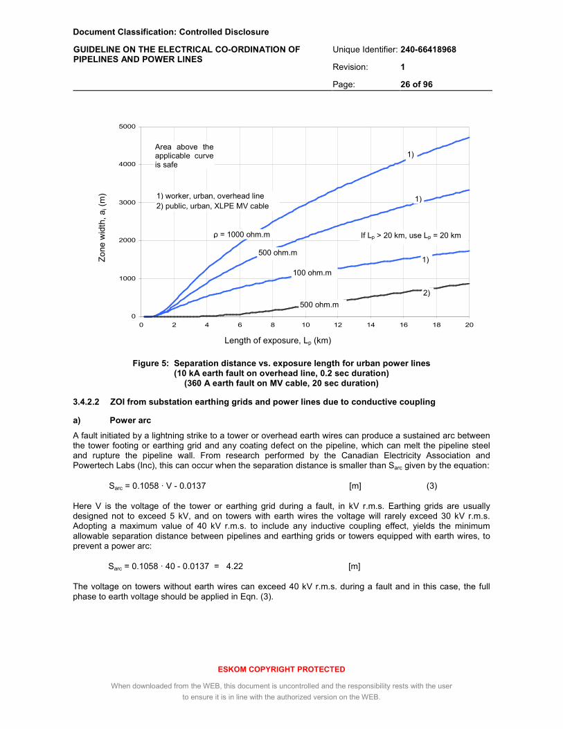
Document Classification: Controlled Disclosure
Unique Identifier: 240-66418968
Revision: 1
GUIDELINE ON THE ELECTRICAL CO-ORDINATION OF PIPELINES AND POWER LINES
Page: 26 of 96
ESKOM COPYRIGHT PROTECTED
When downloaded from the WEB, this document is uncontrolled and the responsibility rests with the user
to ensure it is in line with the authorized version on the WEB.
Figure 5: Separation distance vs. exposure length for urban power lines (10 kA earth fault on overhead line, 0.2 sec duration)
(360 A earth fault on MV cable, 20 sec duration)
3.4.2.2 ZOI from substation earthing grids and power lines due to conductive coupling
a) Power arc
A fault initiated by a lightning strike to a tower or overhead earth wires can produce a sustained arc between the tower footing or earthing grid and any coating defect on the pipeline, which can melt the pipeline steel and rupture the pipeline wall. From research performed by the Canadian Electricity Association and Powertech Labs (Inc), this can occur when the separation distance is smaller than Sarc given by the equation:
Sarc = 0.1058 · V - 0.0137 [m] (3)
Here V is the voltage of the tower or earthing grid during a fault, in kV r.m.s. Earthing grids are usually designed not to exceed 5 kV, and on towers with earth wires the voltage will rarely exceed 30 kV r.m.s. Adopting a maximum value of 40 kV r.m.s. to include any inductive coupling effect, yields the minimum allowable separation distance between pipelines and earthing grids or towers equipped with earth wires, to prevent a power arc:
Sarc = 0.1058 · 40 - 0.0137 = 4.22 [m]
The voltage on towers without earth wires can exceed 40 kV r.m.s. during a fault and in this case, the full phase to earth voltage should be applied in Eqn. (3).
0
1000
2000
3000
4000
5000
0 2 4 6 8 10 12 14 16 18 20
ρ = 1000 ohm.m
500 ohm.m
100 ohm.m
2)
1) worker, urban, overhead line 2) public, urban, XLPE MV cable
1)
1)
1)
Length of exposure, Lp (km)
Zo
ne w
idth
, ai (
m)
Area above the applicable curve is safe
500 ohm.m
If Lp > 20 km, use Lp = 20 km

Document Classification: Controlled Disclosure
Unique Identifier: 240-66418968
Revision: 1
GUIDELINE ON THE ELECTRICAL CO-ORDINATION OF PIPELINES AND POWER LINES
Page: 27 of 96
ESKOM COPYRIGHT PROTECTED
When downloaded from the WEB, this document is uncontrolled and the responsibility rests with the user
to ensure it is in line with the authorized version on the WEB.
b) Earth potential rise
It is also necessary to consider the safety aspect of the earth potential distribution around the faulted tower or grid during an earth fault. With the normal pipeline potential being close to the reference potential of remote earth ( i.e. zero potential), the full EPR at the location of the pipeline is applied across its coating, or to a person in simultaneous contact with the pipeline and earth. The unsafe zone extends to a distance where the EPR has reduced to safe levels (see Fig 6).
Figure 6: Zone of influence for conductive coupling
The zone size is dependant on the magnitude of the fault current, the resistance of the earthing grid or tower footing, the resistivity of the soil, the fault duration and the corresponding voltage limit. Earth wires on power lines decrease the fault resistance which increases the fault current magnitude, but by distributing this current to multiple towers decrease the zone size for individual towers.
Table 4: Zone of influence for conductive coupling from substation earthing grid (0.2 s fault duration)
Zone distance d from edge of earthing grid [m]
Exposure / environment
General public
160 V r.m.s. limit
Authorised personnel
300 V r.m.s. limit
Earthing grid dimensions m and EPR assumed during a
fault
[kV]
urban rural urban rural
10 m x 10 m
10 kV 120 260 57 140
30 m x 30 m
10 kV 340 780 172 400
50 m x 50 m
10 kV 570 1 300 290 670
200 m x 200 m
5 kV 1 100 2 600 500 1 300
500 m x 500 m
5 kV 2 700 6 400 1 300 3 300
Power line towers
A
B
Substation
Substation
d
d
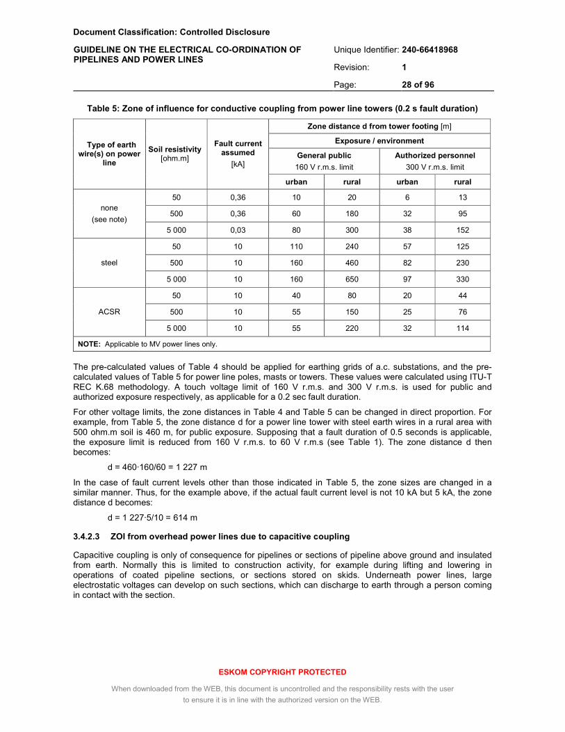
Document Classification: Controlled Disclosure
Unique Identifier: 240-66418968
Revision: 1
GUIDELINE ON THE ELECTRICAL CO-ORDINATION OF PIPELINES AND POWER LINES
Page: 28 of 96
ESKOM COPYRIGHT PROTECTED
When downloaded from the WEB, this document is uncontrolled and the responsibility rests with the user
to ensure it is in line with the authorized version on the WEB.
Table 5: Zone of influence for conductive coupling from power line towers (0.2 s fault duration)
Zone distance d from tower footing [m]
Exposure / environment
General public
160 V r.m.s. limit
Authorized personnel
300 V r.m.s. limit
Type of earth wire(s) on power
line
Soil resistivity [ohm.m]
Fault current assumed
[kA]
urban rural urban rural
50 0,36 10 20 6 13
500 0,36 60 180 32 95 none
(see note) 5 000 0,03 80 300 38 152
50 10 110 240 57 125
500 10 160 460 82 230 steel
5 000 10 160 650 97 330
50 10 40 80 20 44
500 10 55 150 25 76 ACSR
5 000 10 55 220 32 114
NOTE: Applicable to MV power lines only.
The pre-calculated values of Table 4 should be applied for earthing grids of a.c. substations, and the pre-calculated values of Table 5 for power line poles, masts or towers. These values were calculated using ITU-T REC K.68 methodology. A touch voltage limit of 160 V r.m.s. and 300 V r.m.s. is used for public and authorized exposure respectively, as applicable for a 0.2 sec fault duration.
For other voltage limits, the zone distances in Table 4 and Table 5 can be changed in direct proportion. For example, from Table 5, the zone distance d for a power line tower with steel earth wires in a rural area with 500 ohm.m soil is 460 m, for public exposure. Supposing that a fault duration of 0.5 seconds is applicable, the exposure limit is reduced from 160 V r.m.s. to 60 V r.m.s (see Table 1). The zone distance d then becomes:
d = 460·160/60 = 1 227 m
In the case of fault current levels other than those indicated in Table 5, the zone sizes are changed in a similar manner. Thus, for the example above, if the actual fault current level is not 10 kA but 5 kA, the zone distance d becomes:
d = 1 227·5/10 = 614 m
3.4.2.3 ZOI from overhead power lines due to capacitive coupling
Capacitive coupling is only of consequence for pipelines or sections of pipeline above ground and insulated from earth. Normally this is limited to construction activity, for example during lifting and lowering in operations of coated pipeline sections, or sections stored on skids. Underneath power lines, large electrostatic voltages can develop on such sections, which can discharge to earth through a person coming in contact with the section.
Document Classification: Controlled Disclosure
Unique Identifier: 240-66418968
Revision: 1
GUIDELINE ON THE ELECTRICAL CO-ORDINATION OF PIPELINES AND POWER LINES
Page: 29 of 96
ESKOM COPYRIGHT PROTECTED
When downloaded from the WEB, this document is uncontrolled and the responsibility rests with the user
to ensure it is in line with the authorized version on the WEB.
( )[ ])xln(sxlndJU −+⋅⋅ρ⋅=∆
+⋅⋅ρ⋅=
x
sxlndJ
( ) 65.0aa LV5.2d ⋅⋅=
The power – to – pipeline capacitance (and hence the energy transferred by this mechanism) is however very small, and when the safety distances (see 3.8) are observed, the discharge current limit for authorised personnel of 10 mA r.m.s. will not be exceeded for sections of normal length. Still, it could be discernable as a shock similar to that from electrostatic electricity, and could cause a secondary safety hazard if someone working on the pipeline overreacted to this sensation. Moreover, metal contact would produce a spark that could ignite a fuel vapour.
For long, insulated pipelines installed above ground on plinths alongside or underneath power lines, the discharge current could reach 10 mA r.m.s. for lengths in excess of 200 m. This can however be readily mitigated by earthing; even a relatively high resistance earth (100 ohm - 200 ohm) will totally neutralize any capacitive coupling hazard.
The zone of influence is in this case limited to the power line servitude.
3.4.2.4 ZOI from anode ground beds and pipelines due to d.c. leakage
a) Anode ground beds
For homogenous soil, the distance d, from an anode comprising a single horizontal or vertical conductor installed a coke backfill, beyond which the d.c. potential of the soil will be below the 200 mV limit may be calculated using the equation:
[m] (4)
where:
Va is the maximum d.c. voltage applied to the anode [V],
La is the length of the anode [m].
With the anode length adjusted according to soil resistivity, the distance d can vary from a few hundred metres in low resistivity soils to several kilometres in high resistivity soils, for typical CP current requirements.
b) Pipelines
Considering a semi-infinite, straight, ICCP - protected pipeline with evenly distributed coating defects, buried at 1 m depth in homogenous soil, the difference ∆U in the surface potential between two points, one separated by x [m] and one separated by x + s [m] from the pipeline for x ≥ 1m, is given by Eqn (5):
[V]
[V]
(5)
where:
J is the protection current density, [A/m²],
ρ is the soil resistivity, [ohm.m],
d is the pipeline diameter, [m],
s is the span distance between subsequent towers, [m].
For a d.c. potential shift limit of 200 mV at the tower footing, the minimum potential difference ∆U over a full span is 200 mV. The resulting minimum lateral distance x to be applied for a power line with 400 m spans approaching the pipeline diagonally, is as indicated in Table 6, for a large-bore (1 m diameter) pipeline, as a function of protection current density and soil resistivity:
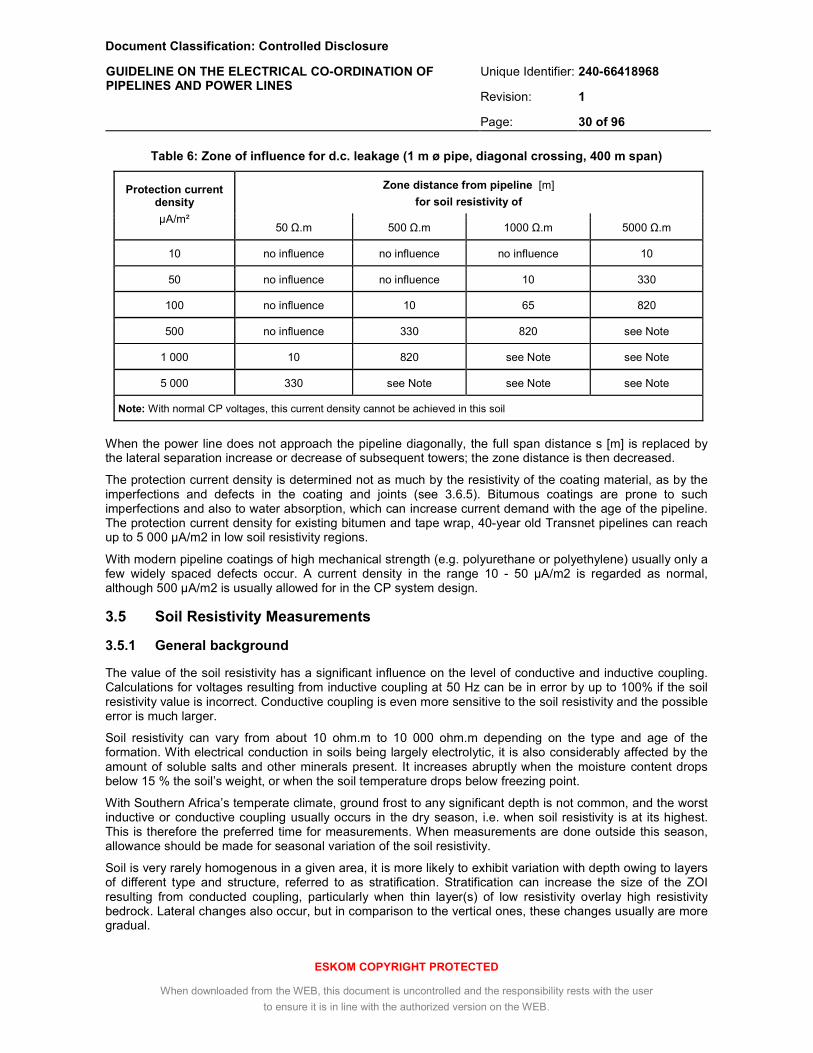
Document Classification: Controlled Disclosure
Unique Identifier: 240-66418968
Revision: 1
GUIDELINE ON THE ELECTRICAL CO-ORDINATION OF PIPELINES AND POWER LINES
Page: 30 of 96
ESKOM COPYRIGHT PROTECTED
When downloaded from the WEB, this document is uncontrolled and the responsibility rests with the user
to ensure it is in line with the authorized version on the WEB.
Table 6: Zone of influence for d.c. leakage (1 m ø pipe, diagonal crossing, 400 m span)
Zone distance from pipeline [m]
for soil resistivity of Protection current
density
µA/m² 50 Ω.m 500 Ω.m 1000 Ω.m 5000 Ω.m
10 no influence no influence no influence 10
50 no influence no influence 10 330
100 no influence 10 65 820
500 no influence 330 820 see Note
1 000 10 820 see Note see Note
5 000 330 see Note see Note see Note
Note: With normal CP voltages, this current density cannot be achieved in this soil
When the power line does not approach the pipeline diagonally, the full span distance s [m] is replaced by the lateral separation increase or decrease of subsequent towers; the zone distance is then decreased.
The protection current density is determined not as much by the resistivity of the coating material, as by the imperfections and defects in the coating and joints (see 3.6.5). Bitumous coatings are prone to such imperfections and also to water absorption, which can increase current demand with the age of the pipeline. The protection current density for existing bitumen and tape wrap, 40-year old Transnet pipelines can reach up to 5 000 µA/m2 in low soil resistivity regions.
With modern pipeline coatings of high mechanical strength (e.g. polyurethane or polyethylene) usually only a few widely spaced defects occur. A current density in the range 10 - 50 µA/m2 is regarded as normal, although 500 µA/m2 is usually allowed for in the CP system design.
3.5 Soil Resistivity Measurements
3.5.1 General background
The value of the soil resistivity has a significant influence on the level of conductive and inductive coupling. Calculations for voltages resulting from inductive coupling at 50 Hz can be in error by up to 100% if the soil resistivity value is incorrect. Conductive coupling is even more sensitive to the soil resistivity and the possible error is much larger.
Soil resistivity can vary from about 10 ohm.m to 10 000 ohm.m depending on the type and age of the formation. With electrical conduction in soils being largely electrolytic, it is also considerably affected by the amount of soluble salts and other minerals present. It increases abruptly when the moisture content drops below 15 % the soil’s weight, or when the soil temperature drops below freezing point.
With Southern Africa’s temperate climate, ground frost to any significant depth is not common, and the worst inductive or conductive coupling usually occurs in the dry season, i.e. when soil resistivity is at its highest. This is therefore the preferred time for measurements. When measurements are done outside this season, allowance should be made for seasonal variation of the soil resistivity.
Soil is very rarely homogenous in a given area, it is more likely to exhibit variation with depth owing to layers of different type and structure, referred to as stratification. Stratification can increase the size of the ZOI resulting from conducted coupling, particularly when thin layer(s) of low resistivity overlay high resistivity bedrock. Lateral changes also occur, but in comparison to the vertical ones, these changes usually are more gradual.

Document Classification: Controlled Disclosure
Unique Identifier: 240-66418968
Revision: 1
GUIDELINE ON THE ELECTRICAL CO-ORDINATION OF PIPELINES AND POWER LINES
Page: 31 of 96
ESKOM COPYRIGHT PROTECTED
When downloaded from the WEB, this document is uncontrolled and the responsibility rests with the user
to ensure it is in line with the authorized version on the WEB.
Numerous tables can be found in the literature that provide soil resistivity ranges based on the type of soil formation. The use of such tables is generally not recommended for coupling studies, partly due to the possibility of stratification which is not visible from the surface, and partly due to the possible incorrect assessment of the soil type due to lack of experience.
3.5.2 Measurement methods
For inductive and conductive coupling calculations, the soil resistivity measurement method used has to penetrate into the deep soil layers to establish if there are any important variations of resistivity with depth. The Wenner four - probe method as described in SANS 10199 (2004), par 3.2.2 or in IEEE 80 (2000), par 13.3 is the simplest and most commonly used method. The probe spacing should be according to tables 7 - 9, depending on the situation under study.
With the Wenner method, soil resistivity soundings at a given probe spacing provide a measure of the apparent resistivity, ρa, taking into account soil layers to a depth of about 80 % of the probe spacing. Unless the soil is homogenous, this apparent resistivity will not be constant with increasing depth.
From the apparent resistivity soundings it is then possible to deduce how many soil layers are present, and what the thickness and resistivity of each of these layers is. A typical example is shown in Fig 7. This relatively complex calculation generally requires the use of computer software (see 3.6.2.c). Graphical curve-matching methods as outlined in SANS 10199 and IEEE 80 may also be used, but are limited to simple soil compositions comprising no more than 2 layers.
Table 7: Wenner soil resistivity soundings for inductive coupling studies
Probe spacing
a
[m]
Specific depth
D = 0.8·a
[m]
Tester reading
R
[ohm]
Geometric factor
K= 2π·a
[m]
Apparent resistivity
ρa = K·R [ohm.m]
0.5 0.4 3.14
1 0.8 6.28
3 2.4 18.85
10 8 62.83
20 16 125.7
30 24 188.5
50 40 314.2
70 56 439.8
100 80 628.3
120 96 754.0

Document Classification: Controlled Disclosure
Unique Identifier: 240-66418968
Revision: 1
GUIDELINE ON THE ELECTRICAL CO-ORDINATION OF PIPELINES AND POWER LINES
Page: 32 of 96
ESKOM COPYRIGHT PROTECTED
When downloaded from the WEB, this document is uncontrolled and the responsibility rests with the user
to ensure it is in line with the authorized version on the WEB.
Table 8: Wenner soil resistivity soundings for conductive coupling studies
Probe spacing
a
[m]
Specific depth
D = 0.8·a
[m]
Tester reading
R
[ohm]
Geometric factor
K= 2π·a
[m]
Apparent resistivity
ρa = K·R [ohm.m]
0.5 0.4 3.14
1 0.8 6.28
2 1.6 12.57
4 3.2 25.13
10 8 62.83
20 16 125.7
30 24 188.5
Table 9: Wenner soil resistivity sounding for soil corrosivity studies
Probe spacing
a
[m]
Specific depth
D = 0.8·a
[m]
Tester reading
R
[ohm]
Geometric factor
K= 2π·a
[m]
Apparent resistivity
ρa = K·R [ohm.m]
2 1.6 12.57
Figure 7: Example of apparent resistivity graph and calculated soil layers

Document Classification: Controlled Disclosure
Unique Identifier: 240-66418968
Revision: 1
GUIDELINE ON THE ELECTRICAL CO-ORDINATION OF PIPELINES AND POWER LINES
Page: 33 of 96
ESKOM COPYRIGHT PROTECTED
When downloaded from the WEB, this document is uncontrolled and the responsibility rests with the user
to ensure it is in line with the authorized version on the WEB.
A further development of the Wenner method is CVES (Continuous Vertical Electrical Sounding), which uses a much larger linear array of probes and enables the calculation of two-dimensional soil resistivity map, used for example to identify underground water, mineral pockets etc. This level of detail cannot be used in current power line / pipeline coupling software, however the raw data from the array can be averaged for each specific sounding depth and these averages analysed similar to Wenner soundings, resulting in improved accuracy.
When used for inductive or conductive coupling studies, a typical CVES array would consist of 36 probes at 10 m intervals, providing penetration ranging from about 8 m to 100 m. To determine the surface resistivity, a measurement with the probes at 0.5 m intervals is also required, or alternately three conventional Wenner measurements at 0.5 m, 1 m and at 3 m probe spacings.
Another alternative, non – invasive method for measuring subsurface resistivity employs inductive electromagnetic (EM) probes. Without the requirement of contact with the soil, these devices can be mounted on a vehicle trailer facilitating fast readings with high spatial resolution. Penetration depth typically varies from 1.5 m to 4.5 m, depending on coil spacing and polarization. EM probes are generally not suitable for deep soil resistivity measurements.
3.5.3 Selection of measurement sites
The selection of sounding sites depends on the study under consideration.
a) For inductive coupling studies, the distance between DSR sounding sites along a parallelism should not exceed 5 km. For short parallelisms (< 10 km) this should be reduced to 2 km, to ensure a better average. These soundings should be done with the probe array perpendicular to the power line axis and centred near this axis, well away from the power line towers and guy wires (preferably at midspan).
b) For conductive coupling studies where no parallelism is present, only a single DSR sounding site is required. The probe array should start near the centre of the side of the substation grid or tower footing facing the pipeline, at a point separated some 10 m from the substation fence or footing and move perpendicularly outwards.
c) For soil corrosivity studies, surface resistivity measurements are recommended at intervals not exceeding 100 m, along the intended pipeline route. In wet, water logged or clay areas, the interval should be reduced to 50 m. Whilst these measurements are not essential for safety calculations, they are essential for an assessment of the corrosion risk and the design of the cathodic protection and monitoring systems. They can also be very useful in the design of a.c. mitigation measures, possibly leading to significant savings in the total length of gradient wire required.
3.5.4 Measurement precautions
a) Avoid sounding sites with the probe array parallel or quasi-parallel to metallic structures such as fences, existing pipelines, underground cables, railways, earthing grids or other man-made structures if possible. If the site has to cross a pipeline or fence, the sounding should be done with the probe array perpendicular to the pipeline or fence.
b) Where possible, the direction of the array should be parallel to the geological strike of the site. The direction of the strike will usually be shown by lines of outcropping rock (ref. SANS 10199).
c) Wenner soundings should be analysed on site to enable identification of measurement errors, due for example to leakage, anomalous effects at the probes, a.c. induction, damaged leads etc. If the apparent resistivity is above 10 000 ohm.m or below 10 ohm.m, or differs greatly from a given trend in geologically similar conditions, the sounding should be regarded as suspect.
d) To ensure adequate measurement resolution with pin spacings of 30 m and larger, the instrument used for Wenner soundings should have a rating of at least 600 V / 2.5 A.
e) Inductive EM probes may be subject to interference near power lines due to corona noise or power line carriers in the frequency band of the instrument’s receiver.

Document Classification: Controlled Disclosure
Unique Identifier: 240-66418968
Revision: 1
GUIDELINE ON THE ELECTRICAL CO-ORDINATION OF PIPELINES AND POWER LINES
Page: 34 of 96
ESKOM COPYRIGHT PROTECTED
When downloaded from the WEB, this document is uncontrolled and the responsibility rests with the user
to ensure it is in line with the authorized version on the WEB.
3.6 Calculation of pipeline voltages
3.6.1 General
A metallic pipeline subject to inductive influence can be modelled by multiple discrete sections, each consisting of a series impedance representing the resistance and inductive reactance of the metal casing, a shunt impedance representing the leakage resistance and capacitive reactance, and a voltage source representing the emf developed in the section by the power line currents, which may be calculated with the formulas developed by Carson and Pollaczek.
In this form the pipeline closely resembles a leaky transmission line, and the theory for calculating the currents and voltages on transmission lines can be effectively applied. In this sense, the transmission line concepts of propagation constant, electric length and characteristic impedance also become valid for a pipeline.
This model further enables the study of mitigation measures. For instance, an earthed electrode connected to the pipeline at a given point will reduce the corresponding section’s shunt resistance to earth, whereas an insulating flange in the pipeline will increase the section’s series resistance. By altering these resistances accordingly in the model, the effect of the measure(s) on the pipeline currents and voltages can be readily observed.
The effect of capacitive coupling can be predicted using the Maxwell potential coefficient method. This is necessary only for above-ground pipelines or pipeline sections inside the servitude without regular earthing points.
The effect of conductive coupling can be modelled using the concept of an equivalent hemispheric electrode for the tower footing or earth grid under study, although this method provides only limited accuracy near the electrode, or when the soil is stratified. More detailed, finite element computer models take account of the exact shape of the electrode and the soil layers, and can accurately predict the potential transfer to a pipeline, and its dissipation with distance from the region of injection.
The theory of capacitive, inductive and conductive coupling is comprehensively covered in CIGRE Guide 95, "Guide on the Influence of High Voltage AC Power Systems on Metallic Pipelines".
In general, for realistic exposures, analysis of the respective coupling components requires the use of suitable computer software.
3.6.2 Software packages
A number of software packages for the calculation of the voltages on pipelines subject to power line coupling are commercially available. Software selected for this purpose should meet the following minimum requirements:
a) Inductive coupling calculations:
• calculation of pipeline voltage and currents during steady state nominal and emergency load conditions with a single or with multiple adjacent power line(s),
• calculation of pipeline voltage and currents during fault conditions at any point on the power line,
• account for tower configuration, conductor sag, earth wires and phase transpositions,
• capable of modelling and optimising the performance of earthing points, insulating flanges, gradient control wires, drainage units, sacrificial anodes and resistive bonds on the pipeline.
b) Capacitive coupling calculations:
• calculation of the voltage of pipelines above ground subject to capacitive coupling from an overhead power line.
Document Classification: Controlled Disclosure
Unique Identifier: 240-66418968
Revision: 1
GUIDELINE ON THE ELECTRICAL CO-ORDINATION OF PIPELINES AND POWER LINES
Page: 35 of 96
ESKOM COPYRIGHT PROTECTED
When downloaded from the WEB, this document is uncontrolled and the responsibility rests with the user
to ensure it is in line with the authorized version on the WEB.
c) Conductive coupling calculations:
• calculation of multi-layer soil model from resistivity measurements,
• earth potential rise (EPR) around a faulted tower or substation grid,
• step potential, touch potential and coating stress on a pipeline traversing the EPR zone.
d) d.c. leakage calculations:
• calculation of the d.c. potential distribution around ICCP-equipped pipelines and ground beds.
e) Fully benchmarked against known calculation or measurement results.
For proper utilisation of these software packages, training of personnel through courses approved by the software developer are essential. Personnel using the software should also have fundamental training in electrical power networks, fault current calculations and electromagnetic coupling phenomena.
3.6.3 Inducing currents on a.c. power lines
3.6.3.1 Currents during normal operation
a) Phase conductor ratings
For inductive coupling calculations under normal operating conditions, the maximum rated current of the power line should be applied as inducing current. This rating is a function of the type and number of sub-conductors in the bundle. Table 10 indicates the rating for standard Eskom overhead conductor types, from DST 32-319 [13].
Rate A is the maximum operating current for normal load conditions, and is used for calculating the pipeline voltage when checking against the limit for a.c. corrosion (3.3.7). Rate B is the maximum operating current for emergency load conditions, and is used for calculating the pipeline voltage when checking against the safety limit (3.3.4).
For XLPE and PILC cables, the conductor ratings depend on the copper cross section as well as the configuration (trefoil, single core or three core) and applicable de-rating factors, depending on the method of installation. These ratings should be obtained from the relevant department in Eskom on a case-by-case basis.
b) Applying phase unbalance
The magnitude of the individual phase currents on 3-phase power lines normally lines differ slightly due to different loading per phase. This introduces a zero-sequence current that has to return through the earthing system of the power line. Zero-sequence or earth return currents can cause inductive coupling over much greater distances than the balanced component.
Local quality of supply standards recommend a maximum of 3% phase current unbalance in supply networks (ref. NRS048-2). For pipeline coupling calculations, an unbalance of 3% may hence be assumed. This can be applied directly to the magnitude of one of the phase currents.
For example, from Table 5, the emergency load current per Dinosaur sub-conductor is 1 380 A r.m.s, i.e. 4 140 A r.m.s. for a 3- conductor bundle. The resulting emergency phase currents on a RWB – sequence circuit with Triple Dinosaur phase conductors will be:
Red phase: IR = 4 140 + 3% = 4 264 A r.m.s, angle 0˚
White phase: IW = 4 140 A r.m.s, angle -120˚
Blue phase: IB = 4 140 A r.m.s, angle 120˚
This method is sufficiently accurate even though the precise definition of phase unbalance is slightly more complex (see 3.1 in NRS048-2).

Document Classification: Controlled Disclosure
Unique Identifier: 240-66418968
Revision: 1
GUIDELINE ON THE ELECTRICAL CO-ORDINATION OF PIPELINES AND POWER LINES
Page: 36 of 96
ESKOM COPYRIGHT PROTECTED
When downloaded from the WEB, this document is uncontrolled and the responsibility rests with the user
to ensure it is in line with the authorized version on the WEB.
Table 10: Standard Eskom overhead conductor ratings (50˚C), from DST 32-319 [13]
Conductor type
Overall diameter
[mm]
d.c. resistance at 20˚C
[ohms]
Rate A
[A r.m.s.]
(see Note)
Rate B
[A r.m.s.]
(see Note)
Tiger 16.52 0.2202 322 466
Wolf 18.13 0.1828 363 528
Lynx 401 584
Chickadee 18.87 0.1427 608 823
Panther 21.00 0.1363 441 642
Pelican 20.70 0.1189 475 698
Bear 23.45 0.1093 521 767
Kingbird 23.90 0.0891 586 831
Goat 25.97 0.0891 618 866
Tern 27.0 0.0718 665 963
Zebra 28.62 0.0674 710 1022
Bunting 881 1324
Dinosaur 35.94 0.0437 938 1380
Beresford 35.56 0.0421 965 1420
Antelope 26.73 0.0773 628 921
Rail 29.59 0.0598 765* 1063*
Squirrel 6.33 1.3677 104 143
Fox 8.37 0.7822 148 203
Mink 10.98 0.4546 206 285
Hare 14.16 0.2733 280 392
Magpie 6.35 2.707 33 40
Acacia 6.24 1.39 108 153
“35” 8.31 0.785 158 216
Pine 10.83 0.462 219 302
Oak 13.95 0.279 297 417
Ash 17.4 0.184 381 548
Yew 28.42 0.0696 761 1073
Sycamore 22.61 0.11 549 775
Elm 424 625
NOTE: Multiply the rated current by the number of sub-conductors in the bundle
c) Effect of transpositions
Transpositions place a different phase closest to the pipeline, normally with the result that, during steady-state induction, the induced pipeline emf is around 120˚ out of phase on either side of the transposition. This produces a pipeline voltage maximum at the transposition.
Because of this important effect on the pipeline voltage profile, it is essential that transpositions are accounted for and that the correct sequence change is applied (a RWB – BRW transposition will have a different effect than a RWB – WRB transposition, for example).
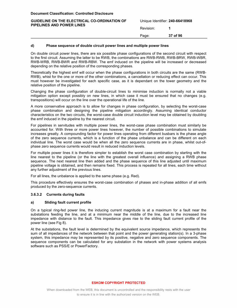
Document Classification: Controlled Disclosure
Unique Identifier: 240-66418968
Revision: 1
GUIDELINE ON THE ELECTRICAL CO-ORDINATION OF PIPELINES AND POWER LINES
Page: 37 of 96
ESKOM COPYRIGHT PROTECTED
When downloaded from the WEB, this document is uncontrolled and the responsibility rests with the user
to ensure it is in line with the authorized version on the WEB.
d) Phase sequence of double circuit power lines and multiple power lines
On double circuit power lines, there are six possible phase configurations of the second circuit with respect to the first circuit. Assuming the latter to be RWB, the combinations are RWB-RWB, RWB-BRW, RWB-WBR, RWB-WRB, RWB-BWR and RWB-RBW. The emf induced on the pipeline will be increased or decreased depending on the relative position of the corresponding phases.
Theoretically the highest emf will occur when the phase configurations in both circuits are the same (RWB-RWB), whist for the one or more of the other combinations, a cancellation or reducing effect can occur. This must however be investigated for each specific case, as it is dependant on the tower geometry and the relative position of the pipeline.
Changing the phase configuration of double-circuit lines to minimise induction is normally not a viable mitigation option except possibly on new lines, in which case it must be ensured that no changes (e.g. transpositions) will occur on the line over the operational life of the line.
A more conservative approach is to allow for changes in phase configuration, by selecting the worst-case phase combination and designing the pipeline mitigation accordingly. Assuming identical conductor characteristics on the two circuits, the worst-case double circuit induction level may be obtained by doubling the emf induced in the pipeline by the nearest circuit.
For pipelines in servitudes with multiple power lines, the worst-case phase combination must similarly be accounted for. With three or more power lines however, the number of possible combinations to simulate increases greatly. A compounding factor for power lines operating from different busbars is the phase angle of the zero sequence currents, which is a function of the phase unbalance and can be different on each individual line. The worst case would be when all the zero sequence currents are in phase, whilst out-of-phase zero sequence currents would result in reduced induction levels.
For multiple power lines it is therefore simpler to establish the worst case combination by starting with the line nearest to the pipeline (or the line with the greatest overall influence) and assigning a RWB phase sequence. The next nearest line then added and the phase sequence of this line adjusted until maximum pipeline voltage is obtained, and then remains fixed. This process is repeated for all lines, each time without any further adjustment of the previous lines.
For all lines, the unbalance is applied to the same phase (e.g. Red).
This procedure effectively ensures the worst-case combination of phases and in-phase addition of all emfs produced by the zero-sequence currents.
3.6.3.2 Currents during faults
a) Sliding fault current profile
On a typical ring-fed power line, the inducing current magnitude is at a maximum for a fault near the substations feeding the line, and at a minimum near the middle of the line, due to the increased line impedance with distance to the fault. This impedance gives rise to the sliding fault current profile of the power line (see Fig 8).
At the substations, the fault level is determined by the equivalent source impedance, which represents the sum of all impedances of the network between that point and the power generating station(s). In a 3-phase system, this impedance may be represented by its positive, negative and zero sequence components. The sequence components can be calculated for any substation in the network with power systems analysis software such as PSS/E or PowerFactory.

Document Classification: Controlled Disclosure
Unique Identifier: 240-66418968
Revision: 1
GUIDELINE ON THE ELECTRICAL CO-ORDINATION OF PIPELINES AND POWER LINES
Page: 38 of 96
ESKOM COPYRIGHT PROTECTED
When downloaded from the WEB, this document is uncontrolled and the responsibility rests with the user
to ensure it is in line with the authorized version on the WEB.
Figure 8: Example of sliding fault current vs. tower number, 220 kV line
To compute the sliding fault current for a given line, the substation’s equivalent source impedances are required without this line in place. The line’s circuit breakers must therefore be temporarily opened in the analysis software when the equivalent source impedances are computed.
With the substation’s equivalent source impedances and the line data (tower configuration and conductor data, checklist A.3) available, the sliding fault current profile can be computed using suitable software. The sub-conductor’s radius and d.c. resistance is provided in Table 10. Only a 1- phase to earth fault needs to be considered, since the residual currents during 2- and 3- phase to earth faults will be of a smaller magnitude.
b) Currents producing tower footing EPR
In power lines equipped with earth wires, the returning fault current is distributed between the faulted tower and the footings of adjacent towers by the earth wires. Some of the current never enters the earth, being carried back to the substation along the earth wires. When calculating the earth potential rise around a tower therefore, this division of the current has to be carefully established. The nominal tower footing resistance in terms of Transmission standard TST41-321 [7] as indicated in Table 11 and the diameter and d.c. resistance of commonly used earth wires, is given in Table 12.
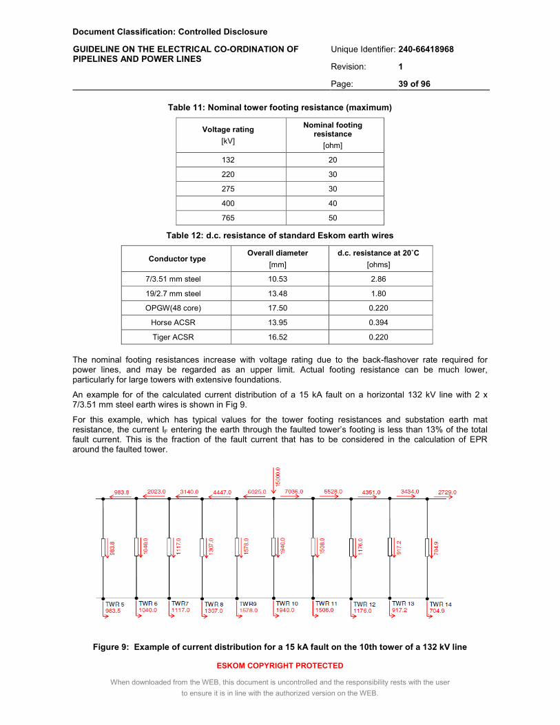
Document Classification: Controlled Disclosure
Unique Identifier: 240-66418968
Revision: 1
GUIDELINE ON THE ELECTRICAL CO-ORDINATION OF PIPELINES AND POWER LINES
Page: 39 of 96
ESKOM COPYRIGHT PROTECTED
When downloaded from the WEB, this document is uncontrolled and the responsibility rests with the user
to ensure it is in line with the authorized version on the WEB.
Table 11: Nominal tower footing resistance (maximum)
Voltage rating
[kV]
Nominal footing resistance
[ohm]
132 20
220 30
275 30
400 40
765 50
Table 12: d.c. resistance of standard Eskom earth wires
Conductor type Overall diameter
[mm]
d.c. resistance at 20˚C
[ohms]
7/3.51 mm steel 10.53 2.86
19/2.7 mm steel 13.48 1.80
OPGW(48 core) 17.50 0.220
Horse ACSR 13.95 0.394
Tiger ACSR 16.52 0.220
The nominal footing resistances increase with voltage rating due to the back-flashover rate required for power lines, and may be regarded as an upper limit. Actual footing resistance can be much lower, particularly for large towers with extensive foundations.
An example for of the calculated current distribution of a 15 kA fault on a horizontal 132 kV line with 2 x 7/3.51 mm steel earth wires is shown in Fig 9.
For this example, which has typical values for the tower footing resistances and substation earth mat resistance, the current IF entering the earth through the faulted tower’s footing is less than 13% of the total fault current. This is the fraction of the fault current that has to be considered in the calculation of EPR around the faulted tower.
Figure 9: Example of current distribution for a 15 kA fault on the 10th tower of a 132 kV line

Document Classification: Controlled Disclosure
Unique Identifier: 240-66418968
Revision: 1
GUIDELINE ON THE ELECTRICAL CO-ORDINATION OF PIPELINES AND POWER LINES
Page: 40 of 96
ESKOM COPYRIGHT PROTECTED
When downloaded from the WEB, this document is uncontrolled and the responsibility rests with the user
to ensure it is in line with the authorized version on the WEB.
∑=
⋅=N
1iiiE IkI
c) Currents producing substation EPR
If there is 1- phase to earth fault in or near a substation, the current IE flowing through the earthing system of the substation causes the EPR. This current is always smaller than the substation’s rated fault level, Id, because a significant portion returns through the earth wires (see Fig 10).
Figure 10: Calculation of electrode current, IE, with a fault inside a substation (from ITU-T Directives, Vol II [30])
There are also two components of IE, namely the transformer’s contribution and the system’s contribution. One of them is decisive from the point of view of EPR.
If the earth fault occurs within the substation, the transformer’s contribution circulates in the station and never enters the earth, hence only the zero-sequence currents coming from the system outside the station in question can cause EPR.
In this case, the current through the earth (i.e. the current from the network flowing through the earthing resistance RA of the station) is given by Eqn (6):
[A] (6)
where
N is number of the lines entering the station,
ki the screening factor of the respective lines (see below), and
Ii the fault current of the line i
If the earth fault occurs outside the substation, the EPR is caused by the zero-sequence current which the station itself feeds into the fault as well as the zero-sequence currents from the system, taking into account the different screening factors (see Fig 11).

Document Classification: Controlled Disclosure
Unique Identifier: 240-66418968
Revision: 1
GUIDELINE ON THE ELECTRICAL CO-ORDINATION OF PIPELINES AND POWER LINES
Page: 41 of 96
ESKOM COPYRIGHT PROTECTED
When downloaded from the WEB, this document is uncontrolled and the responsibility rests with the user
to ensure it is in line with the authorized version on the WEB.
( )∑−
=
⋅−+⋅=1N
1iiiDADE IkkIkI
Figure 11: Calculation of electrode current, IE , with a fault outside a substation (from ITU-T Directives, Vol II [30])
If N-1 is number of the lines entering the station excluding the faulted line, the current flowing through the earthing impedance of the station is given by Eqn (7):
[A] (7)
where
kD is the screening factor of the faulted line,
ki is the screening factor of the remaining lines feeding the station,
IA is the fault current supplied by the substation transformer [A],
Ii is the fault current of the line i [A].
Depending on the amount of current provided by remote stations relative to the current provided by the local transformer, the decisive location of the fault may be either inside the substation or outside. Both situations should be evaluated to determine the worst case EPR at the substation of interest.
In step-down substations, this evaluation should be done on the side of the station transformer which results in the highest fault current. Depending on the transformer rating, this can occur on the lower voltage level.
IE

Document Classification: Controlled Disclosure
Unique Identifier: 240-66418968
Revision: 1
GUIDELINE ON THE ELECTRICAL CO-ORDINATION OF PIPELINES AND POWER LINES
Page: 42 of 96
ESKOM COPYRIGHT PROTECTED
When downloaded from the WEB, this document is uncontrolled and the responsibility rests with the user
to ensure it is in line with the authorized version on the WEB.
3.6.3.3 Determination of the most hazardous location(s) of a power system earth fault
a) Conductive coupling only
For conductive coupling, an earth fault at the mast or tower closest to the pipeline will normally produce the highest coating stress, however all masts or towers with a ZOI overlapping the pipeline route need to be considered individually, taking due account of the power line’s sliding fault current and the local soil conditions.
b) Inductive coupling only
For inductive coupling, the worst location for an earth fault is usually at one end of the exposure. In Fig 12, a fault at position Y will expose the entire pipeline X-Y to a fault level IY, resulting in the highest induced voltage from substation A. The current from substation B will give the highest induced voltage at the fault position X, exposing the entire pipeline to a fault level IX. Since IY is larger than IX, a fault at position Y will give the worst case.
Should the fault occur between X and Y, the fault level from each side would be higher than IX and IY, however the pipeline is only partially exposed. With both breakers closed, the currents flow in opposite directions and the emfs developed in the pipeline will be 180˚ out of phase, resulting in an overall reduction of the induced voltage.
When the pipeline extends beyond substations A or B, point X or Y will move directly opposite substation A or B and the worst case will result from a fault at substation A or B, respectively.
Breakers at substation A and B will usually not open and auto-reclose at precisely the same instant, and at a given instant following the insulation breakdown, the fault may be fed from substation A only, from substation B only, or from both substations. From the viewpoint of inductive coupling, the highest coupling will occur with the fault fed from one (highest) end only. From the viewpoint conductive coupling, the highest EPR around a tower structure will occur with a fault fed from both ends.
For more complex situations, it may be necessary to calculate the pipeline voltage for a number of possible fault locations, to confirm the worst position.
Figure 12: Finding the worst fault position location on arbitrary exposures (adapted from ITU-T Rec K68 [31])
Pipeline

Document Classification: Controlled Disclosure
Unique Identifier: 240-66418968
Revision: 1
GUIDELINE ON THE ELECTRICAL CO-ORDINATION OF PIPELINES AND POWER LINES
Page: 43 of 96
ESKOM COPYRIGHT PROTECTED
When downloaded from the WEB, this document is uncontrolled and the responsibility rests with the user
to ensure it is in line with the authorized version on the WEB.
c) Conductive and inductive coupling
For conductive coupling from a power line encroachment that also contains a parallelism, the coating stress is the vector sum of the inductive and conductive coupling effects. The voltage profile produced by inductive coupling must then be established first (see 3.6.6) and considered in combination with the faulted tower’s EPR, to determine where the highest pipeline coating stress will occur.
3.6.4 Inducing currents on HVDC power lines
HVDC fault or load currents do not produce any inductive coupling, however, during the transient when the current changes from normal to fault level, or during operational switching transients, inductive coupling will occur. This coupling is proportional to the rate of change of the current and can produce considerable pipeline voltages.
The rate of change (dI/dt) is dependant on the impedances inherent to the power line. For HVDC lines of normal construction, the induced transient voltages can be closely approximated by applying a 50 Hz steady state current with a magnitude corresponding to the transient. The d.c. current is replaced by an a.c. waveform with a peak value equal to the d.c. voltage (or Va.c. r.m.s. = 0.707 Vd.c.). The d.c. circuit can be either monopolar (earth return) or bipolar, and the a.c. current should be applied accordingly.
Tests conducted on a pipeline parallel to the Apollo-Pafuri HVDC lines showed that switching transients actually produce higher voltages than earth faults. It was also observed that the duration of switching transient’s peak can exceed 0.2 sec, with some ringing occurring even after 1 sec [32].
The permissible touch voltage should therefore be based on an event duration of 1 sec, and the worst condition considered is a switching transient from 0 A to the line’s maximum current capacity.
HVDC converters also produce steady state harmonic currents, that can couple inductively with the pipeline. A 6 – pulse converter such as Apollo for example, produces a 6th, 12th and 18th current harmonics (300 Hz, 600 Hz and 900 Hz) on the d.c. side. Their magnitude is however limited by means of harmonic filters, typically to less than 0.2% of the load current, and the resulting pipeline voltages do not pose any significant safety hazards.
3.6.5 Pipeline coating resistivity
The variation in coating resistivity, thickness and specific resistance of commonly used pipeline coatings is indicated in Table 13:
Table 13: Typical variation of coating resistivity and thickness
Coating material
Laboratory resistivity
[ohm.m]
Field resistivity, minimum
[ohm.m]
Field resistivity, maximum
[ohm.m]
Coating thickness
[mm]
Specific resistance
[ohm.m²]
Bitumen > 1012 0.2 x 10⁶ 2 x 10⁶ 4 – 10 0.8 x 10³ – 20 x 103
Polyethylene
(e.g. 3LPE, MDPE) 1016 20 x 106 200 x 106 0.8 – 4.0 16 x 103 – 0.8 x 10⁶
Fusion-bonded epoxy
(FBE) 1013 2 x 10⁶ 20 x 106 0.3 – 0.5 0.6 x 10³ – 10 x 103
Polyurethane
(rigid PU, 2-component PU)
1014 20 x 106 200 x 106 0.4 – 3.0 8 x 10³ – 0.6 x 10⁶
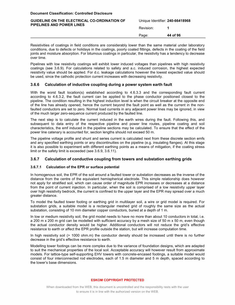
Document Classification: Controlled Disclosure
Unique Identifier: 240-66418968
Revision: 1
GUIDELINE ON THE ELECTRICAL CO-ORDINATION OF PIPELINES AND POWER LINES
Page: 44 of 96
ESKOM COPYRIGHT PROTECTED
When downloaded from the WEB, this document is uncontrolled and the responsibility rests with the user
to ensure it is in line with the authorized version on the WEB.
Resistivities of coatings in field conditions are considerably lower than the same material under laboratory conditions, due to defects or holidays in the coatings, poorly coated fittings, defects in the coating of the field joints and moisture absorption. For bitumous coatings in particular, the resistivity has a tendency to decrease over time.
Pipelines with low resistivity coatings will exhibit lower induced voltages than pipelines with high resistivity coatings (see 3.6.9). For calculations related to safety and a.c. induced corrosion, the highest expected resistivity value should be applied. For d.c. leakage calculations however the lowest expected value should be used, since the cathodic protection current increases with decreasing resistivity.
3.6.6 Calculation of inductive coupling during a power system earth fault
With the worst fault location(s) established according to 4.6.3.3 and the corresponding fault current according to 4.6.3.2, the fault current can be applied to the phase conductor positioned closest to the pipeline. The condition resulting in the highest induction level is when the circuit breaker at the opposite end of the line has already opened, hence the current beyond the fault point as well as the current in the non-faulted conductors are set to zero. Normal load currents in any adjacent power lines may be ignored, in view of the much larger zero-sequence current produced by the faulted line.
The next step is to calculate the current induced in the earth wires during the fault. Following this, and subsequent to data entry of the respective pipeline and power line routes, pipeline coating and soil characteristics, the emf induced in the pipeline sections may be calculated. To ensure that the effect of the power line catenary is accounted for, section lengths should not exceed 50 m.
The pipeline voltage profile and shunt and series current is calculated next from these discrete section emfs and any specified earthing points or any discontinuities on the pipeline (e.g. insulating flanges). At this stage it is also possible to experiment with different earthing points as a means of mitigation, if the coating stress limit or the safety limit is exceeded (see 3.6.9, 3.6.11).
3.6.7 Calculation of conductive coupling from towers and substation earthing grids
3.6.7.1 Calculation of the EPR or surface potential
In homogenous soil, the EPR of the soil around a faulted tower or substation decreases as the inverse of the distance from the centre of the equivalent hemispherical electrode. This simple relationship does however not apply for stratified soil, which can cause order of magnitude EPR increases or decreases at a distance from the point of current injection. In particular, when the soil is comprised of a low resistivity upper layer over high resistivity bedrock, the current is confined to the upper layer and the EPR may spread over a much greater distance.
To model the faulted tower footing or earthing grid in multilayer soil, a wire or grid model is required. For substation grids, a suitable model is a rectangular meshed grid of roughly the same size as the actual substation, consisting of 10 mm diameter copper conductors, buried at a depth of 1 m.
In low or medium resistivity soil, the grid model needs to have no more than about 10 conductors in total, i.e. a 200 m x 200 m grid can be modelled with sufficient accuracy by a mesh size of 50 m x 50 m, even though the actual conductor density would be higher. Additional conductors will not reduce the grid’s effective resistance to earth or affect the EPR profile outside the station, but will increase computation time.
In high resistivity soil (> 1000 ohm.m) the conductor density should be increased until there is no further decrease in the grid’s effective resistance to earth.
Modelling tower footings can be more complex due to the variance of foundation designs, which are adapted to suit the mechanical properties of the local soil. Acceptable accuracy will however result from approximate models. For lattice-type self-supporting EHV towers with concrete-encased footings, a suitable model would consist of four interconnected rod electrodes, each of 1.5 m diameter and 5 m depth, spaced according to the tower’s base dimensions.
Document Classification: Controlled Disclosure
Unique Identifier: 240-66418968
Revision: 1
GUIDELINE ON THE ELECTRICAL CO-ORDINATION OF PIPELINES AND POWER LINES
Page: 45 of 96
ESKOM COPYRIGHT PROTECTED
When downloaded from the WEB, this document is uncontrolled and the responsibility rests with the user
to ensure it is in line with the authorized version on the WEB.
For guyed towers, the anchors and mast support foundations may be similarly modelled, and the model may be scaled down for smaller HV towers. Metallic or reinforced concrete pole-type tower footings may be modelled as a single rod electrode, with dimensions in accordance with the actual footing and concrete foundation diameter.
When there are counterpoises installed, these will have a significant effect and they should be modelled according to their actual dimensions.
Some software packages will permit the modelling of the concrete around the footings, however, being relatively conductive, the concrete may as a first approximation be regarded as being part of the metallic structure. More accurate modelling of the foundations (pads, piles etc.) will also have only a limited influence on the calculated EPR around the tower.
As discussed in 3.6.3.2, only a fraction of the fault current will enter the earth at the tower footing. With this fraction determined, the grid or tower model entered and soil layers specified, it will be possible to compute the potential rise of the footing and the EPR as a function of distance from the tower or grid to the pipeline.
A useful check is that the potential rise should not exceed 5 kV for substation grids or 30 kV for tower footings. Substation grids will only rarely exceed 5 kV, and only in the case of smaller HV substations in poor soils; for Eskom’s EHV substation grids 5 kV is the design limit. In the case of towers equipped with earth wires, a potential of the faulted tower greater than 30 kV is highly unlikely.
3.6.7.2 Calculation of pipeline touch voltage
For a pipeline traversing an EPR zone, some of the potential will be transferred to the pipeline through its coating. Some of this transferred potential can appear on the pipeline well beyond the shared servitude. The pipeline touch voltage (which, for practical purposes, is equal to the coating stress) is then the difference between the local EPR and the voltage transferred to the pipeline (see Fig 13).
Figure 13: Touch voltage resulting from conductive coupling from a faulted tower
To calculate the voltage transferred to the pipeline requires the model to extend to a point where the EPR has effectively diminished, which can be several kilometre. At the ends of this length, an earth point is required to represent the remainder of the pipeline’s coating admittance to earth. A further uncoated 500 m section of pipeline may be specified to provide such an earth.
Earth Potential Rise along pipeline
Voltage transferred to pipeline
Distance along pipeline from fault
Touch voltage near faulted tower
Touch voltage distant from faulted tower
Voltage
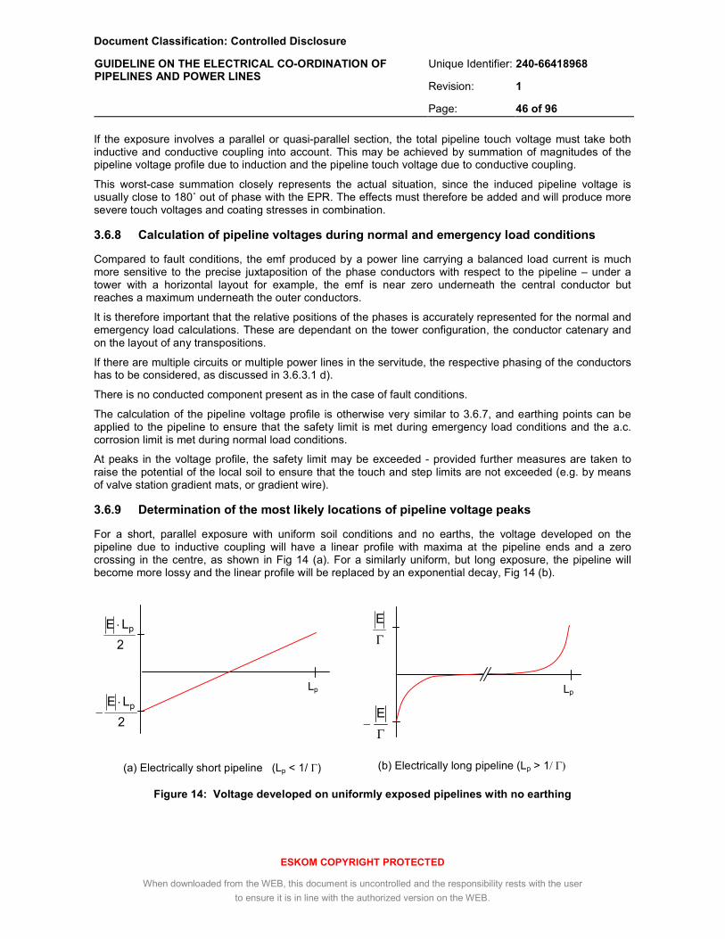
Document Classification: Controlled Disclosure
Unique Identifier: 240-66418968
Revision: 1
GUIDELINE ON THE ELECTRICAL CO-ORDINATION OF PIPELINES AND POWER LINES
Page: 46 of 96
ESKOM COPYRIGHT PROTECTED
When downloaded from the WEB, this document is uncontrolled and the responsibility rests with the user
to ensure it is in line with the authorized version on the WEB.
Γ−
E
If the exposure involves a parallel or quasi-parallel section, the total pipeline touch voltage must take both inductive and conductive coupling into account. This may be achieved by summation of magnitudes of the pipeline voltage profile due to induction and the pipeline touch voltage due to conductive coupling.
This worst-case summation closely represents the actual situation, since the induced pipeline voltage is usually close to 180˚ out of phase with the EPR. The effects must therefore be added and will produce more severe touch voltages and coating stresses in combination.
3.6.8 Calculation of pipeline voltages during normal and emergency load conditions
Compared to fault conditions, the emf produced by a power line carrying a balanced load current is much more sensitive to the precise juxtaposition of the phase conductors with respect to the pipeline – under a tower with a horizontal layout for example, the emf is near zero underneath the central conductor but reaches a maximum underneath the outer conductors.
It is therefore important that the relative positions of the phases is accurately represented for the normal and emergency load calculations. These are dependant on the tower configuration, the conductor catenary and on the layout of any transpositions.
If there are multiple circuits or multiple power lines in the servitude, the respective phasing of the conductors has to be considered, as discussed in 3.6.3.1 d).
There is no conducted component present as in the case of fault conditions.
The calculation of the pipeline voltage profile is otherwise very similar to 3.6.7, and earthing points can be applied to the pipeline to ensure that the safety limit is met during emergency load conditions and the a.c. corrosion limit is met during normal load conditions.
At peaks in the voltage profile, the safety limit may be exceeded - provided further measures are taken to raise the potential of the local soil to ensure that the touch and step limits are not exceeded (e.g. by means of valve station gradient mats, or gradient wire).
3.6.9 Determination of the most likely locations of pipeline voltage peaks
For a short, parallel exposure with uniform soil conditions and no earths, the voltage developed on the pipeline due to inductive coupling will have a linear profile with maxima at the pipeline ends and a zero crossing in the centre, as shown in Fig 14 (a). For a similarly uniform, but long exposure, the pipeline will become more lossy and the linear profile will be replaced by an exponential decay, Fig 14 (b).
(a) Electrically short pipeline (Lp < 1/ Г)
(b) Electrically long pipeline (Lp > 1/ Γ)
Figure 14: Voltage developed on uniformly exposed pipelines with no earthing
Lp
2
LE p⋅−
2
LE p⋅
Lp
Γ
E
−
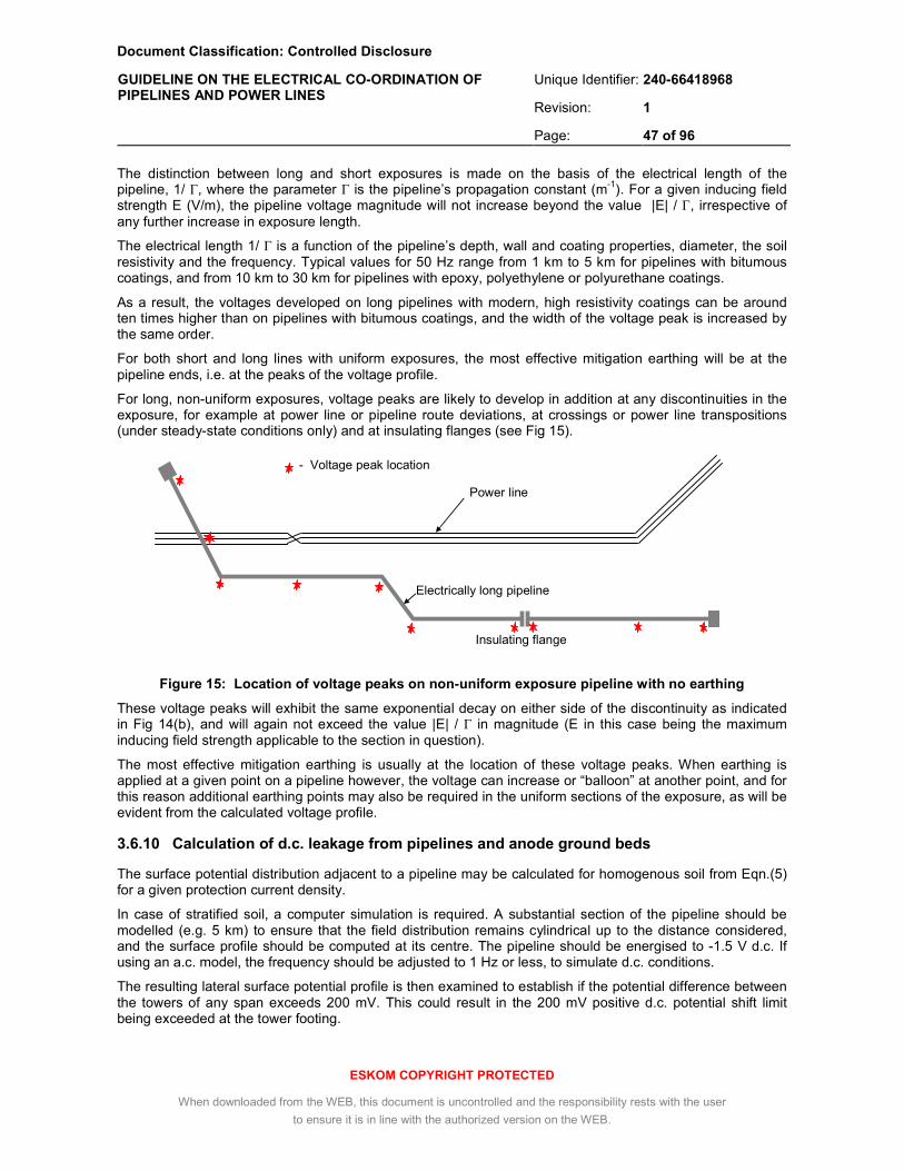
Document Classification: Controlled Disclosure
Unique Identifier: 240-66418968
Revision: 1
GUIDELINE ON THE ELECTRICAL CO-ORDINATION OF PIPELINES AND POWER LINES
Page: 47 of 96
ESKOM COPYRIGHT PROTECTED
When downloaded from the WEB, this document is uncontrolled and the responsibility rests with the user
to ensure it is in line with the authorized version on the WEB.
The distinction between long and short exposures is made on the basis of the electrical length of the pipeline, 1/ Г, where the parameter Г is the pipeline’s propagation constant (m-1). For a given inducing field strength E (V/m), the pipeline voltage magnitude will not increase beyond the value |E| / Г, irrespective of any further increase in exposure length.
The electrical length 1/ Г is a function of the pipeline’s depth, wall and coating properties, diameter, the soil resistivity and the frequency. Typical values for 50 Hz range from 1 km to 5 km for pipelines with bitumous coatings, and from 10 km to 30 km for pipelines with epoxy, polyethylene or polyurethane coatings.
As a result, the voltages developed on long pipelines with modern, high resistivity coatings can be around ten times higher than on pipelines with bitumous coatings, and the width of the voltage peak is increased by the same order.
For both short and long lines with uniform exposures, the most effective mitigation earthing will be at the pipeline ends, i.e. at the peaks of the voltage profile.
For long, non-uniform exposures, voltage peaks are likely to develop in addition at any discontinuities in the exposure, for example at power line or pipeline route deviations, at crossings or power line transpositions (under steady-state conditions only) and at insulating flanges (see Fig 15).
Figure 15: Location of voltage peaks on non-uniform exposure pipeline with no earthing
These voltage peaks will exhibit the same exponential decay on either side of the discontinuity as indicated in Fig 14(b), and will again not exceed the value |E| / Г in magnitude (E in this case being the maximum inducing field strength applicable to the section in question).
The most effective mitigation earthing is usually at the location of these voltage peaks. When earthing is applied at a given point on a pipeline however, the voltage can increase or “balloon” at another point, and for this reason additional earthing points may also be required in the uniform sections of the exposure, as will be evident from the calculated voltage profile.
3.6.10 Calculation of d.c. leakage from pipelines and anode ground beds
The surface potential distribution adjacent to a pipeline may be calculated for homogenous soil from Eqn.(5) for a given protection current density.
In case of stratified soil, a computer simulation is required. A substantial section of the pipeline should be modelled (e.g. 5 km) to ensure that the field distribution remains cylindrical up to the distance considered, and the surface profile should be computed at its centre. The pipeline should be energised to -1.5 V d.c. If using an a.c. model, the frequency should be adjusted to 1 Hz or less, to simulate d.c. conditions.
The resulting lateral surface potential profile is then examined to establish if the potential difference between the towers of any span exceeds 200 mV. This could result in the 200 mV positive d.c. potential shift limit being exceeded at the tower footing.
Electrically long pipeline
ng pipe
Insulating flange
e
- Voltage peak location
Power line

Document Classification: Controlled Disclosure
Unique Identifier: 240-66418968
Revision: 1
GUIDELINE ON THE ELECTRICAL CO-ORDINATION OF PIPELINES AND POWER LINES
Page: 48 of 96
ESKOM COPYRIGHT PROTECTED
When downloaded from the WEB, this document is uncontrolled and the responsibility rests with the user
to ensure it is in line with the authorized version on the WEB.
The anode ground bed should be modelled according to its actual dimensions (typically a linear conductor) energised to the maximum capacity of the CP rectifier (typically 50 V). If the resulting lateral surface potential profile indicates that the potential difference between two towers of a span exceeds 200 mV, the 200 mV limit could be exceeded at the towers where the current returns to earth.
If the ground bed is very close to a tower with an insulated earth wire, the profile has to be examined to ensure that the potential difference across the tower legs or guy anchors does not exceed 400 mV.
Should any of these limits be exceeded, this would serve as an indication that post-installation measurements are required at the tower footings where the current returns to earth, to determine the actual level of interference occurring under operational conditions. (see 3.3.8 (b)).
3.6.11 Calculation of pipeline voltages with mitigation measures applied
The calculation of pipeline voltages due to inductive coupling with mitigation earthing applied is similar to the calculation without earths, as discussed in 3.6.6 and 3.6.8, but with all the earthing points and isolating flanges included in the circuit. The applied earths should include zinc ribbons, earth rods, pump station earthing mats and other earths connected to the pipeline through d.c. decouplers, but should exclude the valve station gradient mats which are connected to the pipeline through SPDs, unless the calculated voltage profile indicates that the SPD’s breakdown voltage is exceeded at any specific valve station, as is likely to occur during fault conditions.
In most software packages, this calculation will only provide the resultant pipeline voltage with respect to remote earth. The touch voltages will be further reduced by gradient mats at valve chambers, and both the touch voltage and the coating stress will be further reduced along pipeline sections with gradient wire(s).
Properly designed and installed gradient mats around valve chambers will invariably bring the step and touch voltages at the chamber to within the required limits, and further simulation of this situation is generally not required. If no external mat is used and only the chamber’s re-bar is earthed, it may be necessary to model this situation specifically.
The effect of the gradient wire also needs to be investigated with a suitable simulation. For example, Fig 16 shows the result of CDEGS simulation of short (150 m) sections of Type II zinc ribbon, installed next to a 1100 mm diameter pipeline with a polymer-modified bitumen coating, in soil consisting of a 15 m thick layer of 500 ohm.m over 1500 ohm.m bedrock. The pipeline is energized to 100 V.
Figure 16: Example of the reduction of touch voltages by zinc ribbon installed in pipeline trench
Pipeline Single ribbon
Double ribbon

Document Classification: Controlled Disclosure
Unique Identifier: 240-66418968
Revision: 1
GUIDELINE ON THE ELECTRICAL CO-ORDINATION OF PIPELINES AND POWER LINES
Page: 49 of 96
ESKOM COPYRIGHT PROTECTED
When downloaded from the WEB, this document is uncontrolled and the responsibility rests with the user
to ensure it is in line with the authorized version on the WEB.
Distance along pipeline from fault
Touch voltage near faulted tower
Voltage Earth Potential Rise
Voltage transferred to pipeline
Touch voltage distant from faulted tower or grid
In this example, a single and double ribbon is seen to reduce the touch voltage by more than 60% and 80% respectively. Generally, this effectiveness decreases with increasing soil resistivity, but it is also sensitive to soil stratification. Each specific situation must therefore be confirmed with a similar calculation.
In the case of conducted coupling, a zinc ribbon section opposite tower footings will also be effective in reducing the touch voltages where there are sharp EPR gradients present – however, the ribbon can have the undesirable effect that the potential transferred to the pipeline as discussed in 3.6.7.2 increases substantially, creating hazardous touch voltages remote from the fault location, as shown in Fig 17:
Figure 17: Touch voltage resulting from conductive coupling from a faulted tower, with zinc ribbon
installed near the faulted tower or grid
Because of this effect, it is not always advisable to install zinc ribbon near close approaches with towers or substation grids - though this may be unavoidable if the coating stress limit is also exceeded. If only the safety limit is exceeded, gradient mats may be used for mitigation in these areas. When zinc ribbon is used, the resultant touch voltage away from the tower or grid must in any event always be evaluated by means of an appropriate simulation model.
3.6.12 Determination of current rating of d.c. decoupling devices, SPDs and cables
Included in the coupling simulation results for both emergency load and fault conditions will be the individual currents flowing to earth at each earthing point, as well as the series current along the length of the pipeline. These current levels have to be compared against the d.c. decoupler device ratings, e.g. the maximum continuous a.c. rating and the fault rating specified in B.2 and B.4 of Annex B. This also applies to d.c. decouplers installed across insulating flanges, which will carry the full series current at the respective point on the pipeline.
If the predicted current levels are higher than the rated values, the device ratings have to be increased, or the earthing resistance of the individual mitigation earthing point has to be reduced (e.g. by splitting the length of the zinc ribbon section in two). If increased device ratings are used, the copper cable cross-section specification B.5 of Annex B has to be increased accordingly.
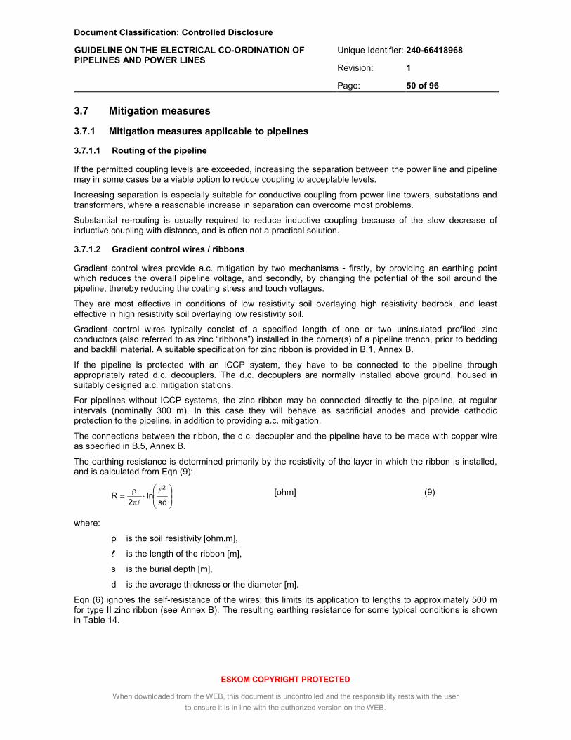
Document Classification: Controlled Disclosure
Unique Identifier: 240-66418968
Revision: 1
GUIDELINE ON THE ELECTRICAL CO-ORDINATION OF PIPELINES AND POWER LINES
Page: 50 of 96
ESKOM COPYRIGHT PROTECTED
When downloaded from the WEB, this document is uncontrolled and the responsibility rests with the user
to ensure it is in line with the authorized version on the WEB.
⋅
π
ρ=
sdln
2R
2l
l
3.7 Mitigation measures
3.7.1 Mitigation measures applicable to pipelines
3.7.1.1 Routing of the pipeline
If the permitted coupling levels are exceeded, increasing the separation between the power line and pipeline may in some cases be a viable option to reduce coupling to acceptable levels.
Increasing separation is especially suitable for conductive coupling from power line towers, substations and transformers, where a reasonable increase in separation can overcome most problems.
Substantial re-routing is usually required to reduce inductive coupling because of the slow decrease of inductive coupling with distance, and is often not a practical solution.
3.7.1.2 Gradient control wires / ribbons
Gradient control wires provide a.c. mitigation by two mechanisms - firstly, by providing an earthing point which reduces the overall pipeline voltage, and secondly, by changing the potential of the soil around the pipeline, thereby reducing the coating stress and touch voltages.
They are most effective in conditions of low resistivity soil overlaying high resistivity bedrock, and least effective in high resistivity soil overlaying low resistivity soil.
Gradient control wires typically consist of a specified length of one or two uninsulated profiled zinc conductors (also referred to as zinc “ribbons”) installed in the corner(s) of a pipeline trench, prior to bedding and backfill material. A suitable specification for zinc ribbon is provided in B.1, Annex B.
If the pipeline is protected with an ICCP system, they have to be connected to the pipeline through appropriately rated d.c. decouplers. The d.c. decouplers are normally installed above ground, housed in suitably designed a.c. mitigation stations.
For pipelines without ICCP systems, the zinc ribbon may be connected directly to the pipeline, at regular intervals (nominally 300 m). In this case they will behave as sacrificial anodes and provide cathodic protection to the pipeline, in addition to providing a.c. mitigation.
The connections between the ribbon, the d.c. decoupler and the pipeline have to be made with copper wire as specified in B.5, Annex B.
The earthing resistance is determined primarily by the resistivity of the layer in which the ribbon is installed, and is calculated from Eqn (9):
[ohm] (9)
where:
ρ is the soil resistivity [ohm.m],
ℓ is the length of the ribbon [m],
s is the burial depth [m],
d is the average thickness or the diameter [m].
Eqn (6) ignores the self-resistance of the wires; this limits its application to lengths to approximately 500 m for type II zinc ribbon (see Annex B). The resulting earthing resistance for some typical conditions is shown in Table 14.

Document Classification: Controlled Disclosure
Unique Identifier: 240-66418968
Revision: 1
GUIDELINE ON THE ELECTRICAL CO-ORDINATION OF PIPELINES AND POWER LINES
Page: 51 of 96
ESKOM COPYRIGHT PROTECTED
When downloaded from the WEB, this document is uncontrolled and the responsibility rests with the user
to ensure it is in line with the authorized version on the WEB.
⋅
πρ
=d
4ln
2R
l
l
Table 14: Earthing resistance provided by gradient control wire, buried 2 m deep
Relectrode for soil resistivity
[ohm]
Electrode type
(Type II Zinc)
100 ohm.m 250 ohm.m 500 ohm.m
100 m zinc ribbon 2.1 5.4 10.8
200 m zinc ribbon 1.1 2.7 5.4
300 m zinc ribbon 0.8 1.9 3.8
400 m zinc ribbon 0.6 1.5 3.0
To limit both the current rating requirement of the d.c. decouplers and the voltage gradient along the ribbon’s length resulting from its self-impedance, ribbon sections should generally not exceed 400 m in length. For optimum current distribution the d.c. decouplers should be connected near the centre and successive sections should not be in direct contact.
The earthing resistance of the zinc ribbon improves only very marginally by using two ribbons as opposed to one. Using two ribbons is only necessary when the coating stress is very high, in which case a second ribbon can provide some improvement (see Fig 19).
3.7.1.3 Vertical earth rods
Like gradient control wires, vertical earth rods can be used to provide an earthing point and thereby reduce the pipeline voltage, but they are not as effective in changing the potential of the earth around the pipeline.
They find application mainly when the resistivity of the upper soil levels is very high compared to the lower levels, when gradient control wires are least effective. They can also be used in combination with gradient control wires, i.e. by connecting one or more vertical rods to the horizontal ribbon, thereby providing access to the low resistivity layers.
Vertical earth rods for this purpose require a borehole to be drilled into the conductive layers and can exceed 100 m in depth. To prevent wall collapse, a steel pipe sleeve is normally inserted, typically of 200 mm – 300 mm diameter. The earth rod may be implemented with Type II zinc ribbon, fitted centrally in the sleeve which is then filled with carbonaceous backfill. This arrangement improves durability and increases the effective contact surface.
For homogenous soil, the earthing resistance of a vertical earth rod is given by Eqn (10):
[ohm] (10)
where:
ρ is the soil resistivity [ohm.m],
ℓ is the length of the ribbon [m],
d is the diameter of the steel sleeving [m].
For stratified soil, the earthing resistance can be calculated using suitable software. The actual resistance can also be measured during the drilling process, to determine if the low value required has been achieved and if further drilling is warranted.
Connection to the pipeline is done in the same manner as gradient control wires, i.e. through a d.c. decoupler in the case of pipelines equipped with ICCP systems or with a direct connection otherwise, using stranded copper wire as specified in B.5, Annex B.
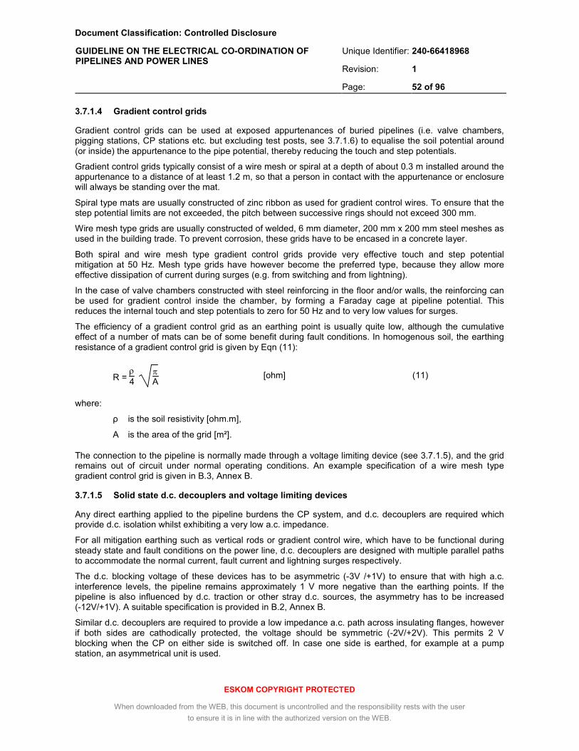
Document Classification: Controlled Disclosure
Unique Identifier: 240-66418968
Revision: 1
GUIDELINE ON THE ELECTRICAL CO-ORDINATION OF PIPELINES AND POWER LINES
Page: 52 of 96
ESKOM COPYRIGHT PROTECTED
When downloaded from the WEB, this document is uncontrolled and the responsibility rests with the user
to ensure it is in line with the authorized version on the WEB.
3.7.1.4 Gradient control grids
Gradient control grids can be used at exposed appurtenances of buried pipelines (i.e. valve chambers, pigging stations, CP stations etc. but excluding test posts, see 3.7.1.6) to equalise the soil potential around (or inside) the appurtenance to the pipe potential, thereby reducing the touch and step potentials.
Gradient control grids typically consist of a wire mesh or spiral at a depth of about 0.3 m installed around the appurtenance to a distance of at least 1.2 m, so that a person in contact with the appurtenance or enclosure will always be standing over the mat.
Spiral type mats are usually constructed of zinc ribbon as used for gradient control wires. To ensure that the step potential limits are not exceeded, the pitch between successive rings should not exceed 300 mm.
Wire mesh type grids are usually constructed of welded, 6 mm diameter, 200 mm x 200 mm steel meshes as used in the building trade. To prevent corrosion, these grids have to be encased in a concrete layer.
Both spiral and wire mesh type gradient control grids provide very effective touch and step potential mitigation at 50 Hz. Mesh type grids have however become the preferred type, because they allow more effective dissipation of current during surges (e.g. from switching and from lightning).
In the case of valve chambers constructed with steel reinforcing in the floor and/or walls, the reinforcing can be used for gradient control inside the chamber, by forming a Faraday cage at pipeline potential. This reduces the internal touch and step potentials to zero for 50 Hz and to very low values for surges.
The efficiency of a gradient control grid as an earthing point is usually quite low, although the cumulative effect of a number of mats can be of some benefit during fault conditions. In homogenous soil, the earthing resistance of a gradient control grid is given by Eqn (11):
R = ρ4
πA [ohm] (11)
where:
ρ is the soil resistivity [ohm.m],
A is the area of the grid [m²].
The connection to the pipeline is normally made through a voltage limiting device (see 3.7.1.5), and the grid remains out of circuit under normal operating conditions. An example specification of a wire mesh type gradient control grid is given in B.3, Annex B.
3.7.1.5 Solid state d.c. decouplers and voltage limiting devices
Any direct earthing applied to the pipeline burdens the CP system, and d.c. decouplers are required which provide d.c. isolation whilst exhibiting a very low a.c. impedance.
For all mitigation earthing such as vertical rods or gradient control wire, which have to be functional during steady state and fault conditions on the power line, d.c. decouplers are designed with multiple parallel paths to accommodate the normal current, fault current and lightning surges respectively.
The d.c. blocking voltage of these devices has to be asymmetric (-3V /+1V) to ensure that with high a.c. interference levels, the pipeline remains approximately 1 V more negative than the earthing points. If the pipeline is also influenced by d.c. traction or other stray d.c. sources, the asymmetry has to be increased (-12V/+1V). A suitable specification is provided in B.2, Annex B.
Similar d.c. decouplers are required to provide a low impedance a.c. path across insulating flanges, however if both sides are cathodically protected, the voltage should be symmetric (-2V/+2V). This permits 2 V blocking when the CP on either side is switched off. In case one side is earthed, for example at a pump station, an asymmetrical unit is used.

Document Classification: Controlled Disclosure
Unique Identifier: 240-66418968
Revision: 1
GUIDELINE ON THE ELECTRICAL CO-ORDINATION OF PIPELINES AND POWER LINES
Page: 53 of 96
ESKOM COPYRIGHT PROTECTED
When downloaded from the WEB, this document is uncontrolled and the responsibility rests with the user
to ensure it is in line with the authorized version on the WEB.
For gradient control mats at valve chambers, an a.c. path is not required during steady state conditions. In this case a voltage limiting device is used that is functional only during transients due to a.c faults or lightning. An SPD (e.g. a GDT or a MOV) with an a.c. clamping voltage around 75 V r.m.s. is suitable for this purpose. A specification for this type of device is provided in B.4, Annex B.
3.7.1.6 Test posts with a.c. coupons
Test posts with carbon steel coupons are usually installed in a.c. induction zones at intervals of approximately 1 km, or at specific locations of high corrosivity, for the purpose of monitoring the performance of the CP and a.c. mitigation systems. The coupons simulate a coating defect of 1 cm², and the a.c. and d.c. coupon currents are directly proportional to the current densities at actual pipeline defects.
Test post terminals are typically housed in pre-cast concrete bunkers or in above- ground galvanized steel cabinets installed on a pre-cast concrete base.
Gradient control mats should not be used at test posts, as these can modify the electric field around the pipeline and thus affect the coupon readings. Test post terminals must however be installed with a “dead-front” arrangement according to NACE RP0177, to prevent accidental contact with the terminal of the cable connected to the pipeline. Test posts may be equipped with a stone or asphalt ground cover around the base for additional protection.
3.7.1.7 Bonding with existing structures
When a new pipeline subject to a.c. coupling is installed next to an existing pipeline, and if there is any possibility of a person being in simultaneous contact, the two pipelines must be cross-bonded with bonding links at intervals not exceeding 1 000 m, to prevent any hazardous potential differences. These can be direct bonds, resistive bonds or d.c. decouplers, as dictated by the CP requirements.
At crossings or close approaches with d.c. railways, pipelines should be bonded to the rails with a directional drainage bond in accordance with SANS 50162.
Pipelines should under no circumstances be bonded to power line towers, tower counterpoises, substation earth grids, power cable screens or any other earthed component of MV, HV or EHV a.c. power networks, as any surges in the power network would then be transferred directly to the pipeline.
Bonding to the earthing of any other infrastructure that is not well defined should generally be avoided.
3.7.1.8 Isolating flanges
Isolating flanges can be used to sectionalise the pipeline and thereby reduce the accumulated voltage in a parallelism. They can also be used to prevent transferred potentials, for example on pipeline spurs or tees.
As each section created requires a separate CP station, this mitigation method can be uneconomical.
Isolating flanges are typically rated less than 15 kV, and a surge diverter with a 1.2 kV breakdown voltage is usually supplied with the unit to prevent damage to the flange in case of voltage surges. Breakdown may not occur during earth faults, as this would defeat the purpose of the isolating flange.
Isolating flanges are not effective with pipelines transporting water or other conductive media, unless an inner lining with the appropriate dielectric properties is used.
When installed in areas where stray d.c. currents are expected, isolating flanges must be housed in an underground chamber to prevent potentially large d.c. currents bypassing the flange through the surrounding soil, causing localised corrosion.
3.7.1.9 Pipeline coatings and coating integrity surveys
The most beneficial pipeline coating type from an a.c. mitigation viewpoint depends on the type of coupling that is most pronounced or problematic. Inductive coupling levels and transferred potentials can be significantly reduced by low resistivity coatings such as bitumen or modified bitumen, especially on long pipelines.
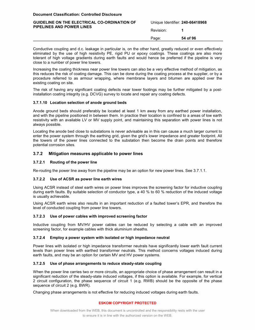
Document Classification: Controlled Disclosure
Unique Identifier: 240-66418968
Revision: 1
GUIDELINE ON THE ELECTRICAL CO-ORDINATION OF PIPELINES AND POWER LINES
Page: 54 of 96
ESKOM COPYRIGHT PROTECTED
When downloaded from the WEB, this document is uncontrolled and the responsibility rests with the user
to ensure it is in line with the authorized version on the WEB.
Conductive coupling and d.c. leakage in particular is, on the other hand, greatly reduced or even effectively eliminated by the use of high resistivity PE, rigid PU or epoxy coatings. These coatings are also more tolerant of high voltage gradients during earth faults and would hence be preferred if the pipeline is very close to a number of power line towers.
Increasing the coating thickness near power line towers can also be a very effective method of mitigation, as this reduces the risk of coating damage. This can be done during the coating process at the supplier, or by a procedure referred to as armour wrapping, where membrane layers and bitumen are applied over the existing coating on site.
The risk of having any significant coating defects near tower footings may be further mitigated by a post-installation coating integrity (e.g. DCVG) survey to locate and repair any coating defects.
3.7.1.10 Location selection of anode ground beds
Anode ground beds should preferably be located at least 1 km away from any earthed power installation, and with the pipeline positioned in between them. In practice their location is confined to a areas of low earth resistivity with an available LV or MV supply point, and maintaining this separation with power lines is not always possible.
Locating the anode bed close to substations is never advisable as in this can cause a much larger current to enter the power system through the earthing grid, given the grid’s lower impedance and greater footprint. All the towers of the power lines connected to the substation then become the drain points and therefore potential corrosion sites.
3.7.2 Mitigation measures applicable to power lines
3.7.2.1 Routing of the power line
Re-routing the power line away from the pipeline may be an option for new power lines. See 3.7.1.1.
3.7.2.2 Use of ACSR as power line earth wires
Using ACSR instead of steel earth wires on power lines improves the screening factor for inductive coupling during earth faults. By suitable selection of conductor type, a 40 % to 60 % reduction of the induced voltage is usually achievable.
Using ACSR earth wires also results in an important reduction of a faulted tower’s EPR, and therefore the level of conducted coupling from power line towers.
3.7.2.3 Use of power cables with improved screening factor
Inductive coupling from MV/HV power cables can be reduced by selecting a cable with an improved screening factor, for example cables with thick aluminium sheaths.
3.7.2.4 Employ a power system with isolated or high impedance neutral
Power lines with isolated or high impedance transformer neutrals have significantly lower earth fault current levels than power lines with earthed transformer neutrals. This method concerns voltages induced during earth faults, and may be an option for certain MV and HV power systems.
3.7.2.5 Use of phase arrangements to reduce steady-state coupling
When the power line carries two or more circuits, an appropriate choice of phase arrangement can result in a significant reduction of the steady-state induced voltages, if this option is available. For example, for vertical 2 circuit configuration, the phase sequence of circuit 1 (e.g. RWB) should be the opposite of the phase sequence of circuit 2 (e.g. BWR).
Changing phase arrangements is not effective for reducing induced voltages during earth faults.

Document Classification: Controlled Disclosure
Unique Identifier: 240-66418968
Revision: 1
GUIDELINE ON THE ELECTRICAL CO-ORDINATION OF PIPELINES AND POWER LINES
Page: 55 of 96
ESKOM COPYRIGHT PROTECTED
When downloaded from the WEB, this document is uncontrolled and the responsibility rests with the user
to ensure it is in line with the authorized version on the WEB.
3.7.2.6 Earth wire isolation to prevent tower footing corrosion
Isolating the towers in the EPR zone of a d.c. energised pipeline or anode ground beds prevents the circulation of d.c. currents on the earth wires and the associated corrosion.
3.7.2.7 Sacrificial anodes to prevent tower footing corrosion
Magnesium or zinc anodes connected to the tower footing or guy anchors when the positive d.c. potential shift exceeds the required 200 mV limit, will prevent damage to the footing. Anodes for this purpose have to be designed according to the actual soil characteristics and the measured d.c. potential shift with the maximum CP current applied.
3.8 Safe working procedures in power line servitudes
3.8.1 Appointment of Electrical Safety Officer (ESO)
3.8.1.1 Prior to any work commencing an Electrical Safety Officer (ESO) shall be appointed by the PO or the PO’s agent. This person shall:
a) be the designated safety officer for the project,
b) have completed Eskom’s ORHVS responsible person training course,
c) be authorised by a ORHVS authorised person (GMR2.1) to work without constant supervision in a power line servitude,
d) have completed the SAECC Electrical Safety Officer training course,
e) have experience in the supervision and management of temporary mitigation measures during pipeline construction, and
f) be furnished with the authority and equipment required to implement and maintain safe working conditions,
g) keep a record of any non-compliance and advise the construction manager and the project safety officer.
3.8.2 General Safe Working procedures
1) No person, equipment or machinery shall enter the HV/EHV servitude without the approval of the ESO. All affected areas shall be suitably demarcated and access restricted to those personnel who have been advised of the hazards and requirements when working underneath or adjacent to HV/EHV power lines.
2) All personnel shall be made aware of and be able to recognize the potential shock hazards and be trained in the approved safety procedures.
3) Pipeline construction personnel shall avoid contact with HV/EHV structures and supports. No mechanical equipment shall come closer than 5 m from any power line tower.
4) Direct connections to the power line tower structures or buried counterpoise earthing system are not permitted under any circumstances. The earthing systems of the power line and the pipeline must be kept separate.
5) Temporary construction sheds, trailers, living quarters, pipe sections, storage areas or vehicle fuelling facilities are not permitted in the HV/EHV servitude.
Document Classification: Controlled Disclosure
Unique Identifier: 240-66418968
Revision: 1
GUIDELINE ON THE ELECTRICAL CO-ORDINATION OF PIPELINES AND POWER LINES
Page: 56 of 96
ESKOM COPYRIGHT PROTECTED
When downloaded from the WEB, this document is uncontrolled and the responsibility rests with the user
to ensure it is in line with the authorized version on the WEB.
6) No mechanical equipment, including mechanical excavators or high lifting machinery, shall be used in the vicinity of Eskom’s apparatus and/or services, without prior written permission having been granted by Eskom. If such permission is granted the applicant must give at least seven working days prior notice of the commencement of work. This allows time for arrangements to be made for supervision and/or precautionary instructions to be issued. The internal assessor must provide the applicant with the details of an Eskom person to be contacted in this regard.
7) All rubber tyre construction vehicles used in the HV/EHV servitude shall be equipped with a steel chain secured to the chassis at one end and freely dragging on the earth at the other, to discharge any electrostatic build-up.
8) The minimum vertical clearance between construction equipment and overhead conductors shall be in accordance with Table 15. The actual height of the conductors at their lowest point shall be measured by means of optical measuring equipment to ensure that this minimum clearance is achieved.
Table 15: Minimum vertical clearance underneath power line conductors
Nominal r.m.s. voltage (kV)
66 88 132 220 275 400 533 d.c. 765
Minimum vertical clearance (m)
3.2 3.4 3.8 4.5 4.9 5.6 6.1 8.5
(from Regulation 15 of the Electrical Machinery Regulations of the OHS Act (Act 85 of 1993))
9) Vehicles such as mobile cranes with extendable members that can potentially exceed this minimum vertical clearance height shall be identified and the operators issued with specific instructions with regard to the maximum permissible extension, prior to doing any work in the HV/EHV servitude.
10) If for any unforeseen reason, the life-threatening situation occurs where a construction vehicle comes into contact with a live HV/EHV conductor or a flash-over occurs, the operator(s) shall remain inside the vehicle and attempt to get it out of the contact situation using ONLY the vehicle’s own power. On NO account shall the operator(s) leave the vehicle and on NO account shall any person approach the vehicle, until the contact situation has been reversed, or until the ESO has received confirmation from the electricity utility that the power line has been de-energized. Arcing may temporarily stop due to the action of the protection, however this in itself shall NOT be taken as an indication that the line is safe, since the line may automatically attempt to re-energize. Effective assistance in this situation entails ensuring that all persons present maintain a safe distance from the vehicle (>10 m) and alarming the electricity utility’s operational centre.
11) Any foreign metal structures exposed during trenching inside or alongside HV/EHV servitudes shall be treated as a live electrical conductor, until measurement proves otherwise. The pipeline shall not be bonded any foreign structures without an assessment by a qualified engineer and written permission from the owner.
12) The use, storage, disposal, treatment or generation of any hazardous substances shall not be permitted in the power line servitude.
3.8.3 Daily measurements
1) Qualified personnel shall measure and record the pipeline voltage to earth to verify that conditions are safe to work (a.c. < 15V r.m.s.), on all sections and on each day prior to the commencement of any construction or other activity involving contact with the pipeline.
2) For pipeline voltage measurements, a voltmeter of suitable range and impedance shall be used. Low resistance earth connections shall be used to avoid induction or capacitive pickup on test leads and related items that could result in erroneous readings on a high impedance instrument. A suitable reference is a metal rod driven into the earth.
Document Classification: Controlled Disclosure
Unique Identifier: 240-66418968
Revision: 1
GUIDELINE ON THE ELECTRICAL CO-ORDINATION OF PIPELINES AND POWER LINES
Page: 57 of 96
ESKOM COPYRIGHT PROTECTED
When downloaded from the WEB, this document is uncontrolled and the responsibility rests with the user
to ensure it is in line with the authorized version on the WEB.
3) Test leads shall be attached to the instrument first and then to the pipeline. After measurement, the leads shall be removed from the pipeline first and from the instrument last.
4) Each time a voltage measurement is made, the following data shall be recorded:
i. location,
ii. time,
iii. date, and
iv. pipe-to-earth voltage.
3.8.4 Temporary earthing
1) Pipelines exhibiting voltages greater than 15 V r.m.s. shall be earthed with temporary driven earth rods. Pipelines parallel to a.c. power systems shall be earthed opposite the midpoint of each span, maximising the distance to the nearest HV/EHV structure.
2) The temporary connections to the pipeline shall be made with earthing clamps that apply firm pressure at the contact point with a mechanically sound connection, and with the coating at the contact point removed down to the bare metal.
3) The connection between the earthing clamp and the earth rod shall be made with 25 mm² stranded copper cable, green PVC insulated.
4) To prevent the risk of personal injury or arc burns, the connection and disconnection of temporary earths shall be carried out in the following order:
a) connection:
i. the earthing clamp is connected to the pipeline,
ii. the earthing cable is connected to the earth rod,
iii. the earthing cable is connected to the earthing clamp.
b) disconnection:
i. the earthing cable is disconnected from the earthing clamp,
ii. the earthing cable is disconnected from the earth rod,
iii. the earthing clamp is removed from the pipeline.
5) Temporary earths shall be left in place until immediately prior to backfilling. Sufficient temporary earths shall be maintained on each section until adequate permanent grounding connections have been made.
6) When the pipeline voltage remains above 15 V r.m.s. in spite of the temporary earth rods, temporary earth mats that extend a minimum of 1 m outside the work area shall be used. The connection between the pipeline earthing clamp and the temporary earth mat shall be made with 16 mm2 or larger stranded copper cable. There shall be no contact between persons over the earth mat and those not over the mat, including the handing over of tools or materials.
3.8.5 Bonding of isolating flanges, joints and couplings
1) Work on isolating flanges, joints, or couplings shall only proceed after the AC status has been verified. A temporary bond across the flange or the use of a properly sized temporary earth mat shall be used to protect personnel while they work on the pipe.
2) When cutting a pipeline, adequate bonding across the point to be cut shall be used, irrespective of the AC voltage measured between the pipeline and earth. When this voltage exceeds 15 V r.m.s, additional earthing shall be installed BEFORE cutting commences.
Document Classification: Controlled Disclosure
Unique Identifier: 240-66418968
Revision: 1
GUIDELINE ON THE ELECTRICAL CO-ORDINATION OF PIPELINES AND POWER LINES
Page: 58 of 96
ESKOM COPYRIGHT PROTECTED
When downloaded from the WEB, this document is uncontrolled and the responsibility rests with the user
to ensure it is in line with the authorized version on the WEB.
3.8.6 Precautions during coating and lowering-in operations
1) Where coating is to be applied at field joints, precautions shall be taken to ensure that equipment contacting the bare pipe is adequately bonded and earthed.
2) For the lowering-in operation, the coated pipeline shall be handled with nonconductive slings. Because the coated pipeline may not be effectively earthed during part of this operation, contact with the bare portion of the pipeline shall be avoided when the support slings are removed from the end of the pipeline.
3.8.7 Work stoppage
1) The ESO shall have liaison with the electrical utility to determine planned switching, outages, and load changes that may affect pipeline voltage. Work involving contact with the pipeline shall be stopped during scheduled switching of the electric power system.
2) WORK SHALL BE STOPPED WHEN ANY LIGHTNING ACTIVITY IS PRESENT.
3.9 Inspection and testing and of pipeline a.c. mitigation components prior to commissioning
a) When the a.c. mitigation measures agreed upon by the Eskom and the Pipeline Operator have been installed, an Eskom representative shall be permitted to inspect all the components of this installation and to perform necessary measurements according to the inspection sheet provided in annex E.
b) Final approval of the a.c. mitigation installation is subject to the outcome of this inspection.
3.10 Long term maintenance requirements of pipeline and power line a.c. mitigation components
a) The a.c. mitigation measures shall be maintained by regular inspection and measurement of the effectiveness of the measures. The interval between inspections shall not exceed 6 months.
b) Maintenance personnel shall be provided with special training to acquaint them with the a.c. mitigation components, measurements and safety requirements.
c) Clear and detailed maintenance records shall be kept available for inspection by an Eskom representative for the full operational lifetime of the pipeline.
4. Authorization
This document has been seen and accepted by:
Name and surname Designation
V Singh Power Plant Technologies Manager
AA Burger Chief Engineer – Eskom Lines Engineering Services
B Haridass Chief Engineer – Eskom Lines Engineering Services
L Motsisi Eskom Land Development
E Grunewald TX Land Development Manager
C Meintjies Land Development Manager: Central
S Mabaso Land Development Manager: Central
N Purdon Land Development Manager: Eastern

Document Classification: Controlled Disclosure
Unique Identifier: 240-66418968
Revision: 1
GUIDELINE ON THE ELECTRICAL CO-ORDINATION OF PIPELINES AND POWER LINES
Page: 59 of 96
ESKOM COPYRIGHT PROTECTED
When downloaded from the WEB, this document is uncontrolled and the responsibility rests with the user
to ensure it is in line with the authorized version on the WEB.
Name and surname Designation
B Maudu Land Development Manager: Northern
L Human Land Development Manager: Northern
X Songcaka Land Development Manager: North West
T Smith Land Development Manager: Southern
B van Geems Land Development Manager: Western
5. Revisions
Date Rev. Compiler Remarks
May 2015 Draft 0.1 B Druif/A Burger First issue.
6. Development team
This guideline was prepared for Line Engineering Services by a Working Group that comprised the following members:
• B Haridass Eskom Line Engineering Services
• A Burger Eskom Line Engineering Services
• L Motsisi Eskom Land & Rights
• B Druif EM Consulting
• P H Pretorius Trans-Africa Projects
7. Acknowledgements
This work was made possible through funding and opportunity provided by Eskom Holding SOC Ltd, in particular the Transmission Line Engineering Services (LES).
Members of the SABS’s Power line and Pipeline Working Group that were consulted during the drafting of this guideline were:
E Livesly Johannesburg Water (Pty) Ltd
T Madonsela Rand Water
B Lourence Department of Water Affairs
N Webb Isinyithi Cathodic Protection
V Sealy-Fisher Isinyithi Cathodic Protection
C Ringas Pipeline Performance Technologies (Pty) Ltd
A Schwab Pipeline Performance Technologies (Pty) Ltd
G Haynes Corrosion &Technology Consultants
A Asraf Sasol Gas
C Downs Transnet
T du Plessis Eskom
K R Hubbard Eskom Corporate Services Division

Document Classification: Controlled Disclosure
Unique Identifier: 240-66418968
Revision: 1
GUIDELINE ON THE ELECTRICAL CO-ORDINATION OF PIPELINES AND POWER LINES
Page: 60 of 96
ESKOM COPYRIGHT PROTECTED
When downloaded from the WEB, this document is uncontrolled and the responsibility rests with the user
to ensure it is in line with the authorized version on the WEB.
V Sewchand Eskom Technology Standardization
F Thuynsma Eskom Industry Association Resource Centre
T Mundie Eskom Industry Association Resource Centre
D Carter LMC Corrosion
R Pillay Paradigm Projects (Pty) Ltd
M Lebenya Paradigm Projects (Pty) Ltd
S Moodley Integrityafrica
G Turner Pipe and Tank Africa Consultants
A Copley IMESA
E Peralta Disa Anodes (Pty) Ltd
B Nkambule Ekuhurleni Metro
D Raath Cathtect Engineering (Pty) Ltd
J Mtombeni SABS

Document Classification: Controlled Disclosure
Unique Identifier: 240-66418968
Revision: 1
GUIDELINE ON THE ELECTRICAL CO-ORDINATION OF PIPELINES AND POWER LINES
Page: 61 of 96
ESKOM COPYRIGHT PROTECTED
When downloaded from the WEB, this document is uncontrolled and the responsibility rests with the user
to ensure it is in line with the authorized version on the WEB.
Annex A – Checklists of particulars required
A.1 - Pipeline Details
1.1 Pipeline name:
1.2
Pipeline construction start date:
Pipeline construction completion date:
1.3 Pipeline pumped product(s):
1.4
Pipeline outer diameter (mm):
Wall thickness (mm):
Wall material:
Section lengths if sectionalised (m):
1.5
Pipeline height / burial depth @ centreline (+/- m):
Pipeline or appurtenances exposed to the public? Y/N
1.6
Coating type and material:
Thickness (mm):
Final insulation strength (kV):
Resistivity (Ω.m) OR Specific Resistance (Ω.m²):
Relative permittivity:
1.7 Pipeline route map or .kmz attached (see Note 1):
1.8 All available soil resistivity data attached:
1.9 Details of cathodic protection attached (see Note 2):
1.10 Details of lightning protection attached (e.g. spark gaps, surge protectors across isolating joints):
1.11 Drawings of valve chambers, pump stations, reservoirs, test post, etc. attached, showing structural steel and other earthing, and final height/level:
1.12 Details of any existing adjacent pipelines, cables, railways and other earthed structures attached:
1.13 Details of all construction vehicles to be used in power line servitude (incl. maximum extended height of booms, vehicles causing excessive vibration etc.) attached:
1.14 Details of activities which will occur (e.g. excavation, blasting, lifting by crane, maintenance inspections by helicopter etc.) provided (see Note 3):
NOTE 1: Clearly indicate the location of all bend points, pump stations, reservoirs, tanks, valve chambers, off takes, test posts and isolating joints
NOTE 2: For ICCP systems, indicate the location and DC current of all anode ground beds and the maximum CP current density expected on the pipeline
NOTE 3: For blasting within 500 m of Eskom’s structures, use separate application in TPC41-1078
Approved by: Date:
Pipeline Applicant / Technical Representative: .

Document Classification: Controlled Disclosure
Unique Identifier: 240-66418968
Revision: 1
GUIDELINE ON THE ELECTRICAL CO-ORDINATION OF PIPELINES AND POWER LINES
Page: 62 of 96
ESKOM COPYRIGHT PROTECTED
When downloaded from the WEB, this document is uncontrolled and the responsibility rests with the user
to ensure it is in line with the authorized version on the WEB.
A.2 – Identification of existing and future power lines / cables affected
Line Name Voltage Level
Tx, Dx or other?
2.1
Existing and planned power lines or cables crossing or running parallel to the pipeline, within 6 km separation distance for overhead lines or 1 km for cables
(ignore overhead lines below 44 kV and cables below 11 kV)
Substation Name Voltage Level
Tx, Dx or other?
2.2
Existing and planned substations within 3 km separation distance from the pipeline
(ignore substations with overhead lines below 44 kV only or with cables below 11 kV only)
2.3 Maps showing route of relevant lines/cables and location of substations attached (alternatively the .kmz, .gdb or .dxf route files):
Approved by: Date:
GIS Specialist / Land & Rights representative: .

Document Classification: Controlled Disclosure
Unique Identifier: 240-66418968
Revision: 1
GUIDELINE ON THE ELECTRICAL CO-ORDINATION OF PIPELINES AND POWER LINES
Page: 63 of 96
ESKOM COPYRIGHT PROTECTED
When downloaded from the WEB, this document is uncontrolled and the responsibility rests with the user
to ensure it is in line with the authorized version on the WEB.
A.3 - Overhead power line details (complete for each overhead line listed in A.2.1)
Figure A.1 - Plan view of power line
3.1 System Voltage ( V r.m.s., phase-phase):
3.2
Station A:
Station B:
3.3 Number of circuits:
3.4
Power line total length (km):
Start of exposure at (km):
End of exposure at (km):
3.5 Transposition(s) at (km) (or None):
(see Note)
3.6
Dominant tower type no. in exposure zone:
Tower sketch attached showing phase and earth conductor attachment height and separation (Y/N):
Avg. span length (m):
Avg. conductor sag at midspan (m):
Avg. tower footing resistance (ohm):
3.7
Phase conductor type and trade name:
Number of sub-conductors:
Spacing between sub-conductors (m):
Earth wire conductor type and trade name:
Earth wires insulated from towers at tower number(s) (or None):
3.8
Peak load current (A r.m.s.):
Emergency load current (A r.m.s.):
Maximum load unbalance between phases (%)
NOTE: Indicate conductor phases (R/W/B) on sketch (at start of exposure, looking towards station B, and if applicable, after each transposition in the exposure)
Approved by: Date:
Power Line Design / Engineering representative: .
.
A B
Substation Substation Exposure zone
Viewpoint

Document Classification: Controlled Disclosure
Unique Identifier: 240-66418968
Revision: 1
GUIDELINE ON THE ELECTRICAL CO-ORDINATION OF PIPELINES AND POWER LINES
Page: 64 of 96
ESKOM COPYRIGHT PROTECTED
When downloaded from the WEB, this document is uncontrolled and the responsibility rests with the user
to ensure it is in line with the authorized version on the WEB.
A.4 - Fault current levels
Line Name Sub Start fault
level (kA) Sub End fault
level (kA)
4.1
Maximum 1 phase-earth fault level at each substation of each power line listed in 2.1 over next 20 years, on the busbar connected to the line
Substation Name
Maximum fault current
(kA)
On busbar of voltage
(kV)
4.4
Maximum 1 phase – earth fault current at each substation listed in 2.2 over next 20 years
4.5 Planning case file (rev number and date)
Approved by: Date:
Power Line Design / Engineering representative: .
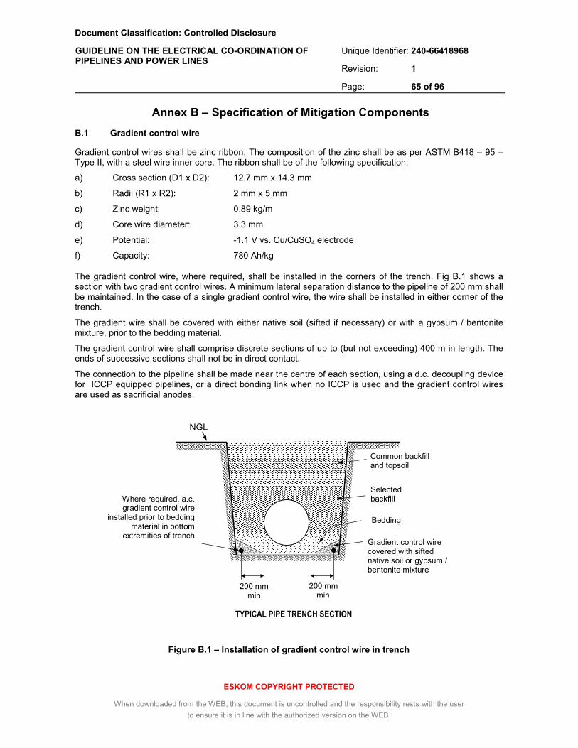
Document Classification: Controlled Disclosure
Unique Identifier: 240-66418968
Revision: 1
GUIDELINE ON THE ELECTRICAL CO-ORDINATION OF PIPELINES AND POWER LINES
Page: 65 of 96
ESKOM COPYRIGHT PROTECTED
When downloaded from the WEB, this document is uncontrolled and the responsibility rests with the user
to ensure it is in line with the authorized version on the WEB.
Annex B – Specification of Mitigation Components
B.1 Gradient control wire
Gradient control wires shall be zinc ribbon. The composition of the zinc shall be as per ASTM B418 – 95 – Type II, with a steel wire inner core. The ribbon shall be of the following specification:
a) Cross section (D1 x D2): 12.7 mm x 14.3 mm
b) Radii (R1 x R2): 2 mm x 5 mm
c) Zinc weight: 0.89 kg/m
d) Core wire diameter: 3.3 mm
e) Potential: -1.1 V vs. Cu/CuSO4 electrode
f) Capacity: 780 Ah/kg
The gradient control wire, where required, shall be installed in the corners of the trench. Fig B.1 shows a section with two gradient control wires. A minimum lateral separation distance to the pipeline of 200 mm shall be maintained. In the case of a single gradient control wire, the wire shall be installed in either corner of the trench.
The gradient wire shall be covered with either native soil (sifted if necessary) or with a gypsum / bentonite mixture, prior to the bedding material.
The gradient control wire shall comprise discrete sections of up to (but not exceeding) 400 m in length. The ends of successive sections shall not be in direct contact.
The connection to the pipeline shall be made near the centre of each section, using a d.c. decoupling device for ICCP equipped pipelines, or a direct bonding link when no ICCP is used and the gradient control wires are used as sacrificial anodes.
Figure B.1 – Installation of gradient control wire in trench
Gradient control wire covered with sifted native soil or gypsum / bentonite mixture
TYPICAL PIPE TRENCH SECTION
NGL
200 mm min
200 mm min
Bedding
Selected backfill
Common backfill and topsoil
Where required, a.c. gradient control wire
installed prior to bedding material in bottom
extremities of trench
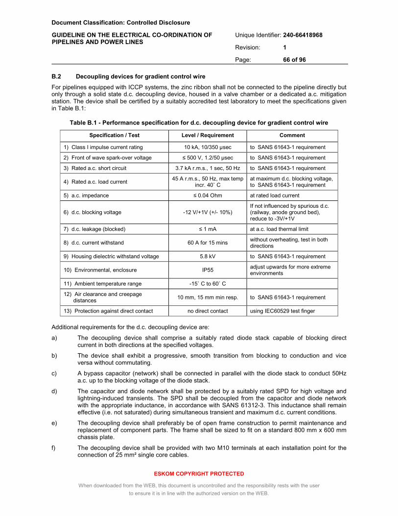
Document Classification: Controlled Disclosure
Unique Identifier: 240-66418968
Revision: 1
GUIDELINE ON THE ELECTRICAL CO-ORDINATION OF PIPELINES AND POWER LINES
Page: 66 of 96
ESKOM COPYRIGHT PROTECTED
When downloaded from the WEB, this document is uncontrolled and the responsibility rests with the user
to ensure it is in line with the authorized version on the WEB.
B.2 Decoupling devices for gradient control wire
For pipelines equipped with ICCP systems, the zinc ribbon shall not be connected to the pipeline directly but only through a solid state d.c. decoupling device, housed in a valve chamber or a dedicated a.c. mitigation station. The device shall be certified by a suitably accredited test laboratory to meet the specifications given in Table B.1:
Table B.1 - Performance specification for d.c. decoupling device for gradient control wire
Specification / Test Level / Requirement Comment
1) Class I impulse current rating 10 kA, 10/350 µsec to SANS 61643-1 requirement
2) Front of wave spark-over voltage ≤ 500 V, 1.2/50 µsec to SANS 61643-1 requirement
3) Rated a.c. short circuit 3.7 kA r.m.s., 1 sec, 50 Hz to SANS 61643-1 requirement
4) Rated a.c. load current 45 A r.m.s., 50 Hz, max temp
incr. 40˚ C at maximum d.c. blocking voltage, to SANS 61643-1 requirement
5) a.c. impedance ≤ 0.04 Ohm at rated load current
6) d.c. blocking voltage -12 V/+1V (+/- 10%) If not influenced by spurious d.c. (railway, anode ground bed), reduce to -3V/+1V
7) d.c. leakage (blocked) ≤ 1 mA at a.c. load thermal limit
8) d.c. current withstand 60 A for 15 mins without overheating, test in both directions
9) Housing dielectric withstand voltage 5.8 kV to SANS 61643-1 requirement
10) Environmental, enclosure IP55 adjust upwards for more extreme environments
11) Ambient temperature range -15˚ C to 60˚ C
12) Air clearance and creepage distances
10 mm, 15 mm min resp. to SANS 61643-1 requirement
13) Protection against direct contact no direct contact using IEC60529 test finger
Additional requirements for the d.c. decoupling device are:
a) The decoupling device shall comprise a suitably rated diode stack capable of blocking direct current in both directions at the specified voltages.
b) The device shall exhibit a progressive, smooth transition from blocking to conduction and vice versa without commutating.
c) A bypass capacitor (network) shall be connected in parallel with the diode stack to conduct 50Hz a.c. up to the blocking voltage of the diode stack.
d) The capacitor and diode network shall be protected by a suitably rated SPD for high voltage and lightning-induced transients. The SPD shall be decoupled from the capacitor and diode network with the appropriate inductance, in accordance with SANS 61312-3. This inductance shall remain effective (i.e. not saturated) during simultaneous transient and maximum d.c. current conditions.
e) The decoupling device shall preferably be of open frame construction to permit maintenance and replacement of component parts. The frame shall be sized to fit on a standard 800 mm x 600 mm chassis plate.
f) The decoupling device shall be provided with two M10 terminals at each installation point for the connection of 25 mm² single core cables.

Document Classification: Controlled Disclosure
Unique Identifier: 240-66418968
Revision: 1
GUIDELINE ON THE ELECTRICAL CO-ORDINATION OF PIPELINES AND POWER LINES
Page: 67 of 96
ESKOM COPYRIGHT PROTECTED
When downloaded from the WEB, this document is uncontrolled and the responsibility rests with the user
to ensure it is in line with the authorized version on the WEB.
g) If housed in a location classified as hazardous in SANS 10108 and ARP0108, for example in case of gas or fuel pipelines, the decoupling device shall be explosion proof (Ex-rated). The nature of the Ex-rating required and the applicable test standard shall be determined by a specialist following a classification study in accordance with SANS 10108.
B.3 Valve chamber gradient control
Gradient control mats may be implemented with zinc spirals or with steel weld mesh mats. An example of a steel weld mesh mat around a valve chamber is shown in Fig B.2. The following is required:
a) A 200 mm x 200 mm weld mesh, of 6 mm diameter steel wire, not galvanized, extending 1.2 m beyond the external wall of the chamber.
b) All overlaps shall be 100 mm minimum, joined at two (2) places with crimped ferrules.
c) For 2 m circular chambers the weld mesh shall be two overlapping panels with a circular cut-out to achieve a 4.4 m x 4.4 m square surround.
d) The weld mesh is centrally located in a 85 mm, 15/19 MPa concrete encasement.
e) The minimum depth of the weld mesh is 300 mm below normal ground level.
f) The panels are connected to the pipeline with at least two (2) cables through a voltage limiting device, cables kept as short as possible (1 m or less).
g) Continuity of the floor reinforcing is established with 2 bars at right angles welded to each bar, or by including a weld mesh layer cut to the floor size, above the structural re-bar.
h) Continuity of the wall reinforcing is established with a continuity ring is installed just below roof height and welded to each vertical bar, and equipped with a connector plate protruding through the wall.
i) The connector plate is connected to the pipeline with two (2) cables through a voltage limiting device, cables kept as short as possible (≤ 1.5 m).
j) If there is any likelihood of a galvanic cell forming between the steel reinforcing bar and the external weld mesh (i.e. dissimilar metals or dissimilar concrete encasement), two separate voltage limiting devices shall be used, as shown in Fig B.2.
k) For air valves with the chamber situated above the pipeline, the mat may be installed at the same depth as the chamber floor.
l) For air valves using pre-cast concrete rings as walls, the steel reinforcing is generally inaccessible and only the reinforcing in the concrete floor is connected to the pipeline.

Document Classification: Controlled Disclosure
Unique Identifier: 240-66418968
Revision: 1
GUIDELINE ON THE ELECTRICAL CO-ORDINATION OF PIPELINES AND POWER LINES
Page: 68 of 96
ESKOM COPYRIGHT PROTECTED
When downloaded from the WEB, this document is uncontrolled and the responsibility rests with the user
to ensure it is in line with the authorized version on the WEB.
Side view
Top view
Figure B.2 – Valve chamber with external weld mesh gradient control mat
Upright reinforcing bars welded to steel continuity ring
Air vent Manhole cover
voltage limiting device
Valve
200 mm x 200 mm x 6 mm diameter external weld mesh
85 mm thick concrete 15/19 MPa
NGL
Hole 20 mm diameter (seal after installation)
Reinforcing steel in concrete floor
1200 mm min
Two (2) cables connected to weld mesh
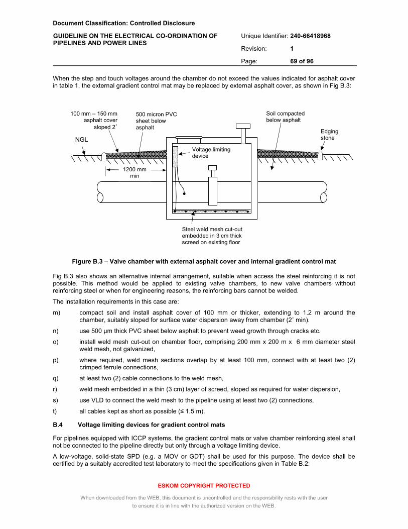
Document Classification: Controlled Disclosure
Unique Identifier: 240-66418968
Revision: 1
GUIDELINE ON THE ELECTRICAL CO-ORDINATION OF PIPELINES AND POWER LINES
Page: 69 of 96
ESKOM COPYRIGHT PROTECTED
When downloaded from the WEB, this document is uncontrolled and the responsibility rests with the user
to ensure it is in line with the authorized version on the WEB.
1200 mm min
When the step and touch voltages around the chamber do not exceed the values indicated for asphalt cover in table 1, the external gradient control mat may be replaced by external asphalt cover, as shown in Fig B.3:
Figure B.3 – Valve chamber with external asphalt cover and internal gradient control mat
Fig B.3 also shows an alternative internal arrangement, suitable when access the steel reinforcing it is not possible. This method would be applied to existing valve chambers, to new valve chambers without reinforcing steel or when for engineering reasons, the reinforcing bars cannot be welded.
The installation requirements in this case are:
m) compact soil and install asphalt cover of 100 mm or thicker, extending to 1.2 m around the chamber, suitably sloped for surface water dispersion away from chamber (2˚ min).
n) use 500 µm thick PVC sheet below asphalt to prevent weed growth through cracks etc.
o) install weld mesh cut-out on chamber floor, comprising 200 mm x 200 m x 6 mm diameter steel weld mesh, not galvanized,
p) where required, weld mesh sections overlap by at least 100 mm, connect with at least two (2) crimped ferrule connections,
q) at least two (2) cable connections to the weld mesh,
r) weld mesh embedded in a thin (3 cm) layer of screed, sloped as required for water dispersion,
s) use VLD to connect the weld mesh to the pipeline using at least two (2) connections,
t) all cables kept as short as possible (≤ 1.5 m).
B.4 Voltage limiting devices for gradient control mats
For pipelines equipped with ICCP systems, the gradient control mats or valve chamber reinforcing steel shall not be connected to the pipeline directly but only through a voltage limiting device.
A low-voltage, solid-state SPD (e.g. a MOV or GDT) shall be used for this purpose. The device shall be certified by a suitably accredited test laboratory to meet the specifications given in Table B.2:
Voltage limiting device
NGL
Steel weld mesh cut-out embedded in 3 cm thick screed on existing floor
Edging stone
Soil compacted below asphalt
500 micron PVC sheet below asphalt
100 mm – 150 mm asphalt cover
sloped 2˚

Document Classification: Controlled Disclosure
Unique Identifier: 240-66418968
Revision: 1
GUIDELINE ON THE ELECTRICAL CO-ORDINATION OF PIPELINES AND POWER LINES
Page: 70 of 96
ESKOM COPYRIGHT PROTECTED
When downloaded from the WEB, this document is uncontrolled and the responsibility rests with the user
to ensure it is in line with the authorized version on the WEB.
Table B.2 - Performance specification for VLD for gradient control mats
Specification / Test Level / Requirement Comment
1) Class I impulse current rating 10 kA, 10/350 µsec to SANS 61643-1 requirement
2) Front of wave spark over voltage ≤ 500 V, 1.2/50 µsec to SANS 61643-1 requirement
3) Response time ≤ 25 nsec
5) Short circuit withstand 3.7 kA r.m.s., 1 sec, 50 Hz to SANS 61643-1 requirement
6) Housing dielectric withstand voltage 5.8 kV to SANS 61643-1 requirement
7) a.c. clamping voltage 75 V r.m.s. (+/- 10%)
8) d.c. breakdown voltage 100 V (+/- 10%)
9) d.c. leakage (blocked) ≤ 1 mA
10) Environmental, enclosure IP55 Adjust upwards for more extreme environments
11) Ambient temperature -15˚ C to 60˚ C
12) Air clearance and creepage distances
10 mm , 40 mm resp. to SANS 61643-1 requirement
13) Protection against direct contact no direct contact using IEC 60529 test finger
If housed in a location classified as hazardous in SANS 10108 and ARP 0108, for example in case of gas or fuel pipelines, the SPD shall be explosion proof (Ex-rated). The nature of the Ex-rating required and the applicable test standard shall be determined by a specialist following a classification study in accordance with SANS 10108.
B.5 Cabling
For connecting of d.c. decoupling devices to the pipeline, insulated 25 mm2 copper earth cables (Cu/PVC) shall be used.
For connection of VLDs to the pipeline, insulated 16 mm2 copper earth cables shall be used.
Copper earth cables shall have a green and yellow colour combination, shall be doubled for redundancy and shall be kept as short as possible, not exceeding 1.5 m in length.
The cable to zinc and cable to weld mesh connections shall comprise of a suitably sized ferrule crimping the cable connection to the weld mesh or to the exposed anode core wire of the zinc ribbon, silver soldering and use of an approved, self-vulcanizing butyl rubber tape to cover over the joint area.
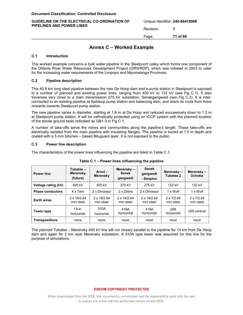
Document Classification: Controlled Disclosure
Unique Identifier: 240-66418968
Revision: 1
GUIDELINE ON THE ELECTRICAL CO-ORDINATION OF PIPELINES AND POWER LINES
Page: 71 of 96
ESKOM COPYRIGHT PROTECTED
When downloaded from the WEB, this document is uncontrolled and the responsibility rests with the user
to ensure it is in line with the authorized version on the WEB.
Annex C – Worked Example
C.1 Introduction
This worked example concerns a bulk water pipeline in the Steelpoort valley which forms one component of the Olifants River Water Resources Development Project (ORWRDP), which was initiated in 2003 to cater for the increasing water requirements of the Limpopo and Mpumalanga Provinces.
C.2 Pipeline description
This 40.8 km long steel pipeline between the new De Hoop dam and a pump station in Steelpoort is exposed to a number of planned and existing power lines, ranging from 400 kV to 132 kV (see Fig C.1). It also traverses very close to a main transmission 275 kV substation, Senakgangwedi (see Fig C.2). It is inter-connected to an existing pipeline at Spitskop pump station and balancing dam, and share its route from there onwards towards Steelpoort pump station.
The new pipeline varies in diameter, starting at 1.8 m at De Hoop and reduced successively down to 1.3 m at Steelpoort pump station. It will be cathodically protected using an ICCP system with the planned location of the anode ground beds indicated as GB1-3 in Fig C.1.
A number of take-offs serve the mines and communities along the pipeline’s length. These take-offs are electrically isolated from the main pipeline with insulating flanges. The pipeline is buried at 1.5 m depth and coated with a 5 mm bitumen – based Bituguard layer. It is not exposed to the public.
C.3 Power line description
The characteristics of the power lines influencing the pipeline are listed in Table C.1.
Table C.1 – Power lines influencing the pipeline
Power line:
Tubatse – Merensky
(future)
Arnot -Merensky
Merensky – Senak
gangwedi
Senak
gangwedi
- Simplon
Merensky –Tubatse 2
Merensky – Uchoba
Voltage rating (kV) 400 kV 400 kV 275 kV 275 kV 132 kV 132 kV
Phase conductors 4 x Tern 2 x Dinosaur 2 x Zebra 2 x Dinosaur 1 x Wolf 1 x Wolf
Earth wires 2 x 19/2.64 mm steel
2 x 19/2.64 mm steel
2 x 19/2.64 mm steel
2 x 19/2.64 mm steel
2 x 7/2.64 mm steel
2 x 7/2.64 mm steel
Tower type t.b.a.
horizontal
510A
horizontal 419A
horizontal 419A
horizontal 248
horizontal 259 vertical
Transpositions none none none none none none
The planned Tubatse – Merensky 400 kV line will run closely parallel to the pipeline for 14 km from De Hoop dam and again for 2 km near Merensky substation. A 510A type tower was assumed for this line for the purpose of simulations.

Document Classification: Controlled Disclosure
Unique Identifier: 240-66418968
Revision: 1
GUIDELINE ON THE ELECTRICAL CO-ORDINATION OF PIPELINES AND POWER LINES
Page: 72 of 96
ESKOM COPYRIGHT PROTECTED
When downloaded from the WEB, this document is uncontrolled and the responsibility rests with the user
to ensure it is in line with the authorized version on the WEB.
Figure C.1 – Pipeline and power line route overview
Tubatse-Merensky
Arnot -Merensky
Merensky-Senakgan
Senakgan-Simplon
Merensky -Uchoba
New pipeline 400 kV line 275 kV line 132 kV line
DSR site
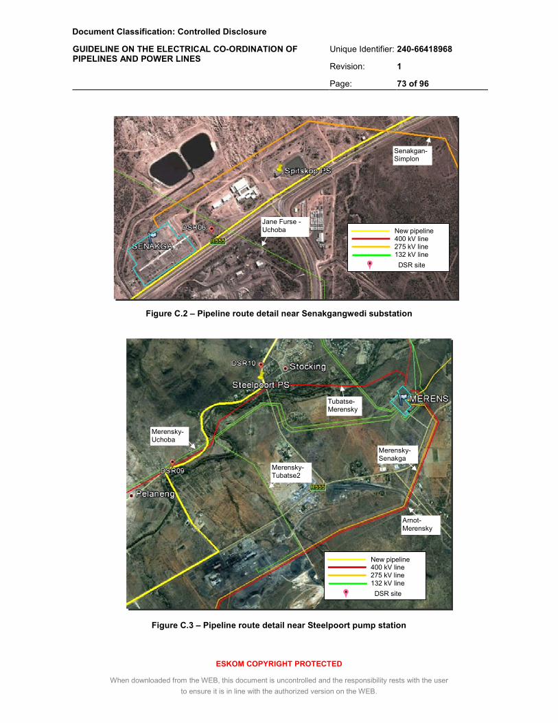
Document Classification: Controlled Disclosure
Unique Identifier: 240-66418968
Revision: 1
GUIDELINE ON THE ELECTRICAL CO-ORDINATION OF PIPELINES AND POWER LINES
Page: 73 of 96
ESKOM COPYRIGHT PROTECTED
When downloaded from the WEB, this document is uncontrolled and the responsibility rests with the user
to ensure it is in line with the authorized version on the WEB.
Figure C.2 – Pipeline route detail near Senakgangwedi substation
Figure C.3 – Pipeline route detail near Steelpoort pump station
Senakgan-Simplon
Jane Furse - Uchoba New pipeline
400 kV line 275 kV line 132 kV line
DSR site
GB3
Merensky-Senakga
Arnot- Merensky
Merensky-Tubatse2
Merensky-Uchoba
Tubatse-Merensky
New pipeline 400 kV line 275 kV line 132 kV line
DSR site

Document Classification: Controlled Disclosure
Unique Identifier: 240-66418968
Revision: 1
GUIDELINE ON THE ELECTRICAL CO-ORDINATION OF PIPELINES AND POWER LINES
Page: 74 of 96
ESKOM COPYRIGHT PROTECTED
When downloaded from the WEB, this document is uncontrolled and the responsibility rests with the user
to ensure it is in line with the authorized version on the WEB.
C.4 Determination of applicable limits
The existing 400 kV and 275 kV lines are equipped with teleprotection, with a resultant cumulative fault duration of 0.2 sec or less (see Table 2). The new 400 kV line will be similarly equipped. The two 132 kV lines use stepped distance protection, with a worst-case cumulative fault duration of 0.5 sec. To ensure a conservative design however, a total cumulative fault clearance time of 1 sec is assumed for all the power lines.
From Table 1, the resulting safety voltage limits for occupational exposure during earth faults are 60 V r.m.s. (touch) and 135 V r.m.s. (step), with no surface layer modification. With an asphalt layer, these values increase to 640 V r.m.s (touch) and 2 400 V r.m.s. (step).
For the bitumous coating, the maximum permissible coating stress is 900 V r.m.s.
For steady state conditions, the touch voltage is limited to 15 V r.m.s. during emergency load.
The a.c. corrosion voltage limits adopted by the pipeline operator are 10 V r.m.s. and 4 V r.m.s, for areas with soil resistivities larger or smaller than 25 ohm.m respectively, applicable during normal load.
C.5 Determination of zones of influence
The ZOI for inductive coupling is 31.7 km, from Eqn (1) (see 3.4.2.1). with Vmax = 60 V r.m.s., ku = 1, kp = 0.8, If = 20 kA r.m.s., Lp = 20 km and ρ = 1 000 ohm.m.
The ZOI for conductive coupling from the substations is 6.5 km, from Table 4, for a 200 m x 200 m rural substation and with the voltage limit adjusted from 300 V r.m.s. to 60 V r.m.s.
The ZOI for conductive coupling from power line towers is 1.15 km, from Table 5, for a power line with steel earth wires and 500 ohm.m surface resistivity, again adjusted to a 60 V r.m.s. voltage limit.
The ZOI of the anode ground bed is 1 775 m, from Eqn (4), for a 60 m anode energised to 50 V, for a maximum EPR of 200 mV.
The ZOI of the pipeline in terms of d.c. leakage is 330 m, from Table 6, for an assumed maximum protection current density of 500 A/m² and a soil surface resistivity of 500 ohm.m.
With all these zone limits exceeded, soil resistivity measurements were required for the detailed calculations of each case.
C.6 Soil resistivity analysis
Surface resistivity measurements were made at 100 m intervals along the pipeline route with a Wenner array and 2 m probe spacing. The surface resistivity was found to be relatively low, averaging at 50 ohm.m and with a number of sections having a resistivity less than 25 ohm.m (see Fig C.4).
Deep soil resistivity measurements were made at the sites labelled DSR01 – DSR10 in figs C.1 – C.3., using a CVES linear array of 12 electrodes spaced at 10 m intervals. The subsequent analysis of the resulting data showed that the soil in this area can be accurately represented by just three layers, with the upper two layers in the range 6 ohm.m – 150 ohm.m and the lower (infinite) layer in the range 90 ohm.m – 1 000 ohm.m.
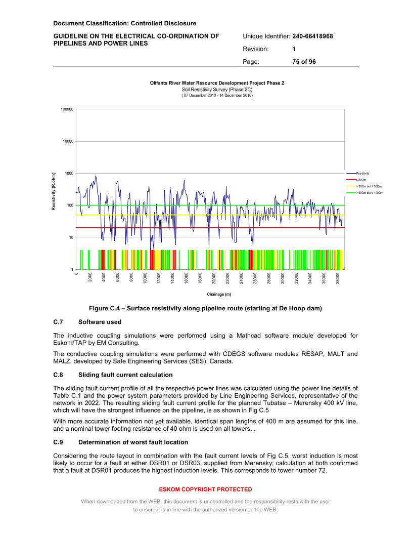
Document Classification: Controlled Disclosure
Unique Identifier: 240-66418968
Revision: 1
GUIDELINE ON THE ELECTRICAL CO-ORDINATION OF PIPELINES AND POWER LINES
Page: 75 of 96
ESKOM COPYRIGHT PROTECTED
When downloaded from the WEB, this document is uncontrolled and the responsibility rests with the user
to ensure it is in line with the authorized version on the WEB.
Olifants River Water Resource Development Project Phase 2
Soil Resistivity Survey (Phase 2C)( 07 December 2010 - 14 December 2010)
1
10
100
1000
10000
100000
0
2000
4000
6000
8000
100
00
120
00
140
00
160
00
180
00
200
00
220
00
240
00
260
00
280
00
300
00
320
00
340
00
360
00
380
00
Chainage (m)
Re
sis
tiv
ity
(R
.oh
m) Resistivity
≤ 20Ωm
> 20Ωm but ≤ 50Ωm
> 50Ωm but ≤ 100Ωm
Figure C.4 – Surface resistivity along pipeline route (starting at De Hoop dam)
C.7 Software used
The inductive coupling simulations were performed using a Mathcad software module developed for Eskom/TAP by EM Consulting.
The conductive coupling simulations were performed with CDEGS software modules RESAP, MALT and MALZ, developed by Safe Engineering Services (SES), Canada.
C.8 Sliding fault current calculation
The sliding fault current profile of all the respective power lines was calculated using the power line details of Table C.1 and the power system parameters provided by Line Engineering Services, representative of the network in 2022. The resulting sliding fault current profile for the planned Tubatse – Merensky 400 kV line, which will have the strongest influence on the pipeline, is as shown in Fig C.5
With more accurate information not yet available, identical span lengths of 400 m are assumed for this line, and a nominal tower footing resistance of 40 ohm is used on all towers. .
C.9 Determination of worst fault location
Considering the route layout in combination with the fault current levels of Fig C.5, worst induction is most likely to occur for a fault at either DSR01 or DSR03, supplied from Merensky; calculation at both confirmed that a fault at DSR01 produces the highest induction levels. This corresponds to tower number 72.

Document Classification: Controlled Disclosure
Unique Identifier: 240-66418968
Revision: 1
GUIDELINE ON THE ELECTRICAL CO-ORDINATION OF PIPELINES AND POWER LINES
Page: 76 of 96
ESKOM COPYRIGHT PROTECTED
When downloaded from the WEB, this document is uncontrolled and the responsibility rests with the user
to ensure it is in line with the authorized version on the WEB.
Figure C.5 – Sliding fault current profile on Tubatse-Merensky 400 kV line
C.10 Determination of tower voltages and currents
In terms of TST 41-321, the earth wires of the Tubatse – Merensky 400 kV line will be isolated from towers within 800 m of the pipeline route, and each tower isolator equipped with a 12 kV spark gap. Accordingly, these towers are initially removed from the simulation model. For a fault at tower at 72, the calculated tower voltages and footing currents are as indicated in Fig C.6. The voltage at this tower reaches 26 kV and the current 650 A.
Figure C.6 - Tower voltages and currents, fault at tower 72, Tubatse – Merensky 400 kV line (towers within 800 m insulated, with 12 kV spark gaps)
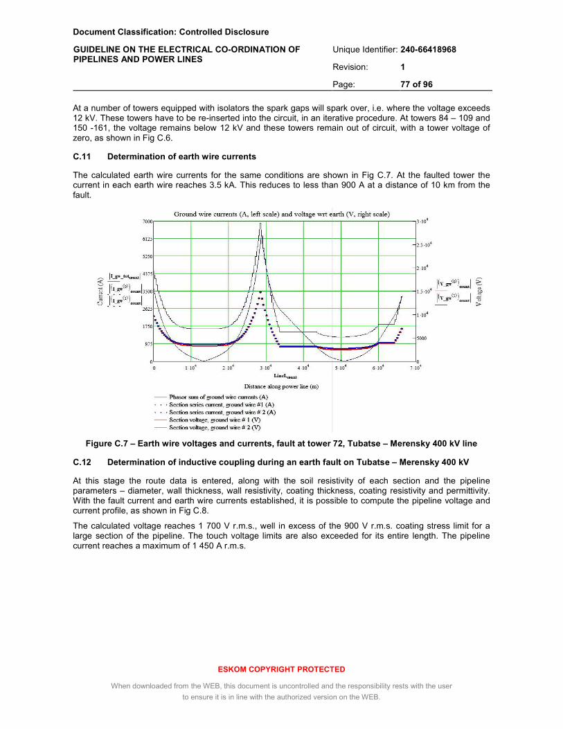
Document Classification: Controlled Disclosure
Unique Identifier: 240-66418968
Revision: 1
GUIDELINE ON THE ELECTRICAL CO-ORDINATION OF PIPELINES AND POWER LINES
Page: 77 of 96
ESKOM COPYRIGHT PROTECTED
When downloaded from the WEB, this document is uncontrolled and the responsibility rests with the user
to ensure it is in line with the authorized version on the WEB.
At a number of towers equipped with isolators the spark gaps will spark over, i.e. where the voltage exceeds 12 kV. These towers have to be re-inserted into the circuit, in an iterative procedure. At towers 84 – 109 and 150 -161, the voltage remains below 12 kV and these towers remain out of circuit, with a tower voltage of zero, as shown in Fig C.6.
C.11 Determination of earth wire currents
The calculated earth wire currents for the same conditions are shown in Fig C.7. At the faulted tower the current in each earth wire reaches 3.5 kA. This reduces to less than 900 A at a distance of 10 km from the fault.
Figure C.7 – Earth wire voltages and currents, fault at tower 72, Tubatse – Merensky 400 kV line
C.12 Determination of inductive coupling during an earth fault on Tubatse – Merensky 400 kV
At this stage the route data is entered, along with the soil resistivity of each section and the pipeline parameters – diameter, wall thickness, wall resistivity, coating thickness, coating resistivity and permittivity. With the fault current and earth wire currents established, it is possible to compute the pipeline voltage and current profile, as shown in Fig C.8.
The calculated voltage reaches 1 700 V r.m.s., well in excess of the 900 V r.m.s. coating stress limit for a large section of the pipeline. The touch voltage limits are also exceeded for its entire length. The pipeline current reaches a maximum of 1 450 A r.m.s.

Document Classification: Controlled Disclosure
Unique Identifier: 240-66418968
Revision: 1
GUIDELINE ON THE ELECTRICAL CO-ORDINATION OF PIPELINES AND POWER LINES
Page: 78 of 96
ESKOM COPYRIGHT PROTECTED
When downloaded from the WEB, this document is uncontrolled and the responsibility rests with the user
to ensure it is in line with the authorized version on the WEB.
Figure C.8 – Pipeline induction, fault at tower 72 (near DSR01), no mitigation
C.13 Determination of inductive coupling during an earth fault, other power lines
Repeating the same procedure for earth faults on the other lines of Table C.1, it was established that the coating stress and safety limits are similarly exceeded. For the Arnot-Merensky line, a fault near DSR07 produces a maximum of 2 300 V r.m.s.
C.14 Determination of inductive coupling during steady state conditions
Under normal load conditions, the pipeline will be influenced by the currents of all the power lines listed in Table C.1 simultaneously. This calculation is dependant on the phase sequence of the respective phases of the lines. With the actual phase sequence of the future line unknown, and the sequences of the existing lines not made available, the worst-case combination had to be accounted for.
Following the procedure described in 3.6.3.1 d) of the main text, starting with the Tubatse-Merensky line and adding further lines one at a time, the resulting worst-case voltage is established as shown in Fig C.9 (red curve), for a 3% current unbalance applied to all the Red phases.
The induced voltage on the pipeline for these conditions is well in excess of the 15 V r.m.s. safety limit and the a.c. corrosion limits of 4 V r.m.s. and 10 V r.m.s. respectively.
60 V
900 V
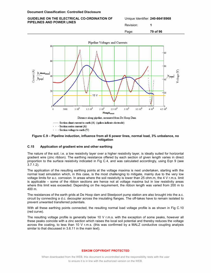
Document Classification: Controlled Disclosure
Unique Identifier: 240-66418968
Revision: 1
GUIDELINE ON THE ELECTRICAL CO-ORDINATION OF PIPELINES AND POWER LINES
Page: 79 of 96
ESKOM COPYRIGHT PROTECTED
When downloaded from the WEB, this document is uncontrolled and the responsibility rests with the user
to ensure it is in line with the authorized version on the WEB.
Figure C.9 – Pipeline induction, influence from all 6 power lines, normal load, 3% unbalance, no mitigation
C.15 Application of gradient wire and other earthing
The nature of the soil, i.e. a low resistivity layer over a higher resistivity layer, is ideally suited for horizontal gradient wire (zinc ribbon). The earthing resistance offered by each section of given length varies in direct proportion to the surface resistivity indicated in Fig C.4, and was calculated accordingly, using Eqn 9 (see 3.7.1.2).
The application of the resulting earthing points at the voltage maxima is next undertaken, starting with the normal load simulation which, in this case, is the most challenging to mitigate, mainly due to the very low voltage limits for a.c. corrosion. In areas where the soil resistivity is lower than 25 ohm.m, the 4 V r.m.s. limit is applicable – some of the ribbon sections are hence not at voltage maxima but in low resistivity areas where this limit was exceeded. Depending on the requirement, the ribbon length was varied from 200 m to 400 m.
The resistances of the earth grids at De Hoop dam and Steelpoort pump station are also brought into the a.c. circuit by connecting a d.c. decoupler across the insulating flanges. The off-takes have to remain isolated to prevent unwanted transferred potentials.
With all these earthing points connected, the resulting normal load voltage profile is as shown in Fig C.10 (red curve).
The resulting voltage profile is generally below 10 V r.m.s. with the exception of some peaks, however all these peaks coincide with a zinc section which raises the local soil potential and thereby reduces the voltage across the coating, to less than 10 V r.m.s. (this was confirmed by a MALZ conductive coupling analysis similar to that discussed in 3.6.11 in the main text).
15 V

Document Classification: Controlled Disclosure
Unique Identifier: 240-66418968
Revision: 1
GUIDELINE ON THE ELECTRICAL CO-ORDINATION OF PIPELINES AND POWER LINES
Page: 80 of 96
ESKOM COPYRIGHT PROTECTED
When downloaded from the WEB, this document is uncontrolled and the responsibility rests with the user
to ensure it is in line with the authorized version on the WEB.
Figure C.10 – Pipeline induction, influence from all 6 power lines, normal load, 3% unbalance, with mitigation
Under emergency load conditions, the current increases by a factor of 1.45 for the Tern conductors of Tubatse-Merensky (from Table 10). Assuming, conservatively, that all the power lines operate 1.45 times normal load, the resulting voltage profile will increase by the same factor. The 15 V r.m.s. safety limit is still met under these conditions.
Each spike on the horizontal axis of Fig C.10 represents the current drawn from the pipeline by a zinc ribbon section, or by a terminal earth grid, through a d.c. decoupler. The considerable number of earthing points required near Steelpoort pump station is the result of the voltage “ballooning” in this area when the other earths are applied.
The maximum current spike level is 40 A r.m.s., which is within the standard d.c. decoupler steady state rating of 45 A r.m.s. (see Table B.2, annex B). The pipeline series current (blue curve) peaks at 106 A r.m.s., however at the insulating flanges at the terminals, the current levels are lower; 4 A r.m.s at De Hoop and 14 A r.m.s at Steelpoort pump station, both well below the d.c. decoupler rating.
C.16 Determination of inductive coupling during an earth fault, with mitigation
Fig C.11 shows the pipeline voltage profile for the same earth fault as in Fig C.8, but with the earthing points connected. The maximum voltage is now reduced to 300 V r.m.s., thus the coating stress limit of 900 V r.m.s. is not exceeded. The 60 V r.m.s. safety limit is however still exceeded.
15 V
10 V

Document Classification: Controlled Disclosure
Unique Identifier: 240-66418968
Revision: 1
GUIDELINE ON THE ELECTRICAL CO-ORDINATION OF PIPELINES AND POWER LINES
Page: 81 of 96
ESKOM COPYRIGHT PROTECTED
When downloaded from the WEB, this document is uncontrolled and the responsibility rests with the user
to ensure it is in line with the authorized version on the WEB.
Figure C.11 – Pipeline induction, fault at tower 72 (near DSR01), with mitigation
The induction level was next calculated for a number of other possible fault locations on Tubatse – Merensky and the other power lines. The maximum pipeline voltage was found to occur for a fault on Arnot – Merensky tower 389, reaching 400 V r.m.s. The shape of the voltage profile is then very different to Fig C.11 with the maximum occurring near chainage 3 200 m, i.e. at a minimum in Fig C.11.
Shunt current spikes in Fig C.11 are limited to 670 A r.m.s. and no other fault conditions produced a higher current. The 3.7 kA r.m.s fault current rating of a standard d.c. decoupler (see Table B.2, annex B) is therefore sufficient, with a considerable safety margin.
From this analysis it was evident that, taking account of the inductive coupling component, the coating stress limit will be met, but further mitigation is required at the pipeline appurtenances to ensure that the safety limit is met.
C.17 Determination of conductive coupling from power line towers
The smallest separation between the power line and any tower footing occurs at tower 4 of the Senakgangwedi – Simplon power line, at a distance of 25 m. The fault current level at this tower is 14 kA, of which 5 kA will return through the footing and the remainder through the earth wires.
With the tower footing modelled as described in 3.6.7.1 of the main text, the resulting pipeline coating stress is 1 550 V r.m.s. (see Fig C.12). With the 900 V r.m.s. coating limit thus exceeded, a gradient control wire is required. A single 200 m zinc ribbon section reduces the coating stress opposite this tower to 320 V r.m.s. (see Fig C.13).
60 V

Document Classification: Controlled Disclosure
Unique Identifier: 240-66418968
Revision: 1
GUIDELINE ON THE ELECTRICAL CO-ORDINATION OF PIPELINES AND POWER LINES
Page: 82 of 96
ESKOM COPYRIGHT PROTECTED
When downloaded from the WEB, this document is uncontrolled and the responsibility rests with the user
to ensure it is in line with the authorized version on the WEB.
Figure C.12 – Pipeline coating stress during a twr 4 earth fault (5 kA tower energization) – Senakgangwedi – Simplon 275 kV, no mitigation
Figure C.13 – Pipeline coating stress during a twr 4 earth fault (5 kA tower energization) – Senakgangwedi – Simplon 275 kV, single 200 m ribbon
Comparing figs C.12 and C.13, the potential transfer effect of the zinc ribbon as discussed in 3.6.7.2 and 3.6.11 is clearly evident, with the pipeline coating stress increasing beyond the ends of the ribbon section. This effect is muted however by the bitumen coating’s low resistivity, and the maximum voltage remains below 500 V r.m.s.

Document Classification: Controlled Disclosure
Unique Identifier: 240-66418968
Revision: 1
GUIDELINE ON THE ELECTRICAL CO-ORDINATION OF PIPELINES AND POWER LINES
Page: 83 of 96
ESKOM COPYRIGHT PROTECTED
When downloaded from the WEB, this document is uncontrolled and the responsibility rests with the user
to ensure it is in line with the authorized version on the WEB.
With the coating stress due to inductive coupling less than 100 V r.m.s. for a fault at this tower, the total (inductive plus conductive) stress is less than 600 V r.m.s., i.e. well below the 900 V r.m.s. limit.
A similar analysis was performed for other towers close to the pipeline, and similar mitigation measures where required. The results were consistent with the above, but with lower voltage levels.
C.18 Determination of conductive coupling from substation grids
C.18.1 Senakgangwedi substation
A phase to earth fault in the 275 kV network at Senakgangwedi substation would result in a total fault current of 16 kA r.m.s., taking account of upgrades until 2022 (no planning or case files were available beyond this date). Of this, a maximum of 10 kA r.m.s. will enter the earth mat and the remainder distribute into the earth wires of the connected power lines, determined in accordance with 3.6.3.2 c) of the main text.
The earthing grid size is 250 m x 150 m and the soil represented by DSR06 (comprising of a 22 m thick layer of 6 ohm.m over an infinite lower layer of 125 ohm.m). The resulting earth potential rise (EPR) at the station is 900 V r.m.s. (see fig. C.14). This value is lower than usual for a station of this size, due to the low soil resistivity in this area.
Figure C.14 – Senakgangwedi EPR during an earth fault (10 kA grid energization), from centre of earthing grid
The lateral distance from the pipeline to the edge of the earthing grid is 22 m. Without mitigation, the resulting maximum pipeline coating stress is 570 V r.m.s. (see fig. C.15). In combination with the inductive component, the coating stress limit is approached, and a single 400 m ribbon section was specified. This reduces the maximum touch voltage to 190 V r.m.s. (see Fig C.16).

Document Classification: Controlled Disclosure
Unique Identifier: 240-66418968
Revision: 1
GUIDELINE ON THE ELECTRICAL CO-ORDINATION OF PIPELINES AND POWER LINES
Page: 84 of 96
ESKOM COPYRIGHT PROTECTED
When downloaded from the WEB, this document is uncontrolled and the responsibility rests with the user
to ensure it is in line with the authorized version on the WEB.
Figure C.15 – Pipeline coating stress during an earth fault (10 kA grid energization) - along pipeline opposite Senakgangwedi, no mitigation
.
Figure C.16 – Pipeline coating stress during an earth fault (10 kA grid energization) - along pipeline opposite Senakgangwedi, single 400 m ribbon

Document Classification: Controlled Disclosure
Unique Identifier: 240-66418968
Revision: 1
GUIDELINE ON THE ELECTRICAL CO-ORDINATION OF PIPELINES AND POWER LINES
Page: 85 of 96
ESKOM COPYRIGHT PROTECTED
When downloaded from the WEB, this document is uncontrolled and the responsibility rests with the user
to ensure it is in line with the authorized version on the WEB.
In Fig C.16, small voltage discontinuities are observed near the ends of the gradient wire, and some potential is transferred to the pipeline sections beyond the ends. This is however mitigated by the low coating and soil resistivities, making these increases acceptable.
C.18.2 Merensky substation
At Merensky substation, the maximum earth fault level occurs on the 132 kV side, at 31 kA r.m.s. Without mitigation, the maximum pipeline coating stress due to this substation’s EPR is 400 V r.m.s., in spite of the 2 030 m separating the pipeline and substation. In combination with the inductive component the total coating stress will, however, remain below the 900 V r.m.s. limit.
The already extensive use of zinc ribbon on this section of the pipeline for inductive coupling mitigation will further reduce the conducted component and no additional zinc ribbon is required.
C.19 Determination of d.c. coupling from the cathodic protection system
C.19.1 Coupling from pipeline
The d.c. potential gradient adjacent to the pipeline was calculated for an average pipeline voltage of -1.5 V d.c. and a surface soil resistivity of 250 ohm.m, representing the higher of the measured values. It is assumed that the coating defects are evenly distributed.
The results indicate that a minimum lateral distance of 150 m from the pipeline must be maintained to prevent a soil potential gradient greater than 1 mV/m, which over a 400 m span can result in a d.c. gradient exceeding 400 mV (see Fig C.17). Since this distance is smaller than the 800 m required by the earthing standard TST-41-321, the standard should be maintained, and the earth wires of towers within 800 m of the pipeline should be isolated.
Figure C.17 – Earth d.c. potential gradient vs. lateral distance from pipeline, 5 mm Bituguard coating, 250 ohm.m surface soil

Document Classification: Controlled Disclosure
Unique Identifier: 240-66418968
Revision: 1
GUIDELINE ON THE ELECTRICAL CO-ORDINATION OF PIPELINES AND POWER LINES
Page: 86 of 96
ESKOM COPYRIGHT PROTECTED
When downloaded from the WEB, this document is uncontrolled and the responsibility rests with the user
to ensure it is in line with the authorized version on the WEB.
C.19.2 Coupling from anode ground beds
The planned location of the anode ground beds is indicated as GB1 – GB3 in Fig C.1 – C.3. Each ground bed consists of a single 60 m horizontal conductor installed in a carbonaceous backfill.
The d.c. ground shift was calculated around these using the soil layers of the respective DSR region. At 10 A nominal CP current, an earth potential rise in excess of +200 mV extends to the following distances around the ground beds:
• GB1 : 700 m
• GB2 : 900 m
• GB3 : 800 m
For the power line towers falling inside these distances, isolating the earth wires would prevent hazardous current levels from entering the power lines.
None of the planned ground beds can cause a voltage gradient in excess of 400 mV across the legs or anchors of the nearest towers.
C.20 Pipeline a.c. mitigation requirements
From the analysis, it was evident that the applicable steady state limits can be met with selected gradient wire sections and with the earthing systems at the pipeline’s extremities connected to the pipeline.
It was further evident that the 900 V r.m.s. coating stress limit for fault conditions will be met, but the 60 V r.m.s. touch limit can be exceeded at most of the valve stations and other pipeline appurtenances, depending on the location of the fault, indicating that further localised mitigation is required.
Externally, gradient control mats installed around the pipeline appurtenances and connected to the pipeline through appropriately rated VLDs will constitute an effective mitigation method.
Alternately, a 10 cm – 15 cm thick asphalt layer can be used around the appurtenances, increasing the touch voltage limit to 640 V r.m.s., a level not exceeded for any of the fault conditions.
In addition to the external protection method (i.e. gradient control mat or asphalt layer), further protection is required inside the valve chambers. This may be done by connecting the chamber’s reinforcing steel to the pipeline, also through a VLD. For this purpose, the steel reinforcing has to be made galvanically continuous, and equipped with a suitable connection point, prior to concrete casting.
The specific requirements are summarised in tables C.4 and C.5.
C.21 Protection of existing pipeline
To prevent hazardous potentials between the new pipeline and the existing pipeline running from Spitskop pump station to Steelpoort pump station, cross-bonds are required at points where simultaneous contact is possible for a maintenance person standing between the pipelines or pipeline attachments. Cross-bonds are also recommended at regular intervals not exceeding 1 000 m, using either resistive or direct bonds or d.c. decoupling devices, as dictated by the cathodic protection system’s requirements.
The existing valve chambers not equipped with a.c. mitigation require retrofitting with internal earth mats comprising a suitably shaped steel weld mesh cut-out, laid on the floor and encased in a 3 cm thick screed layer. The earth mat is connected to the pipeline through a VLD.

Document Classification: Controlled Disclosure
Unique Identifier: 240-66418968
Revision: 1
GUIDELINE ON THE ELECTRICAL CO-ORDINATION OF PIPELINES AND POWER LINES
Page: 87 of 96
ESKOM COPYRIGHT PROTECTED
When downloaded from the WEB, this document is uncontrolled and the responsibility rests with the user
to ensure it is in line with the authorized version on the WEB.
Table C.4 : Location and lengths of zinc ribbon
Start chainage [m]
End chainage [m]
Site description Electrode description
4 230 4 690 near DSR01 1 x 400 m ribbon
7 850 8 250 between DSR02 & DSR03 1 x 400 m ribbon
8 820 9 220 between DSR02 &DSR03 1 x 400 m ribbon
9 970 11 570 near DSR03 4 x 400 m ribbon
13 920 14 720 near DSR04 2 x 400 m ribbon
16 840 18 440 near DSR05 4 x 400 m ribbon
19 940 20 340 at Dwars river bridge 1 x 400 m ribbon
21 400 21 800 at old farm ruins 1 x 400 m ribbon
23 120 23 520 at Xtrada mine entrance 1 x 400 m ribbon
24 380 24 780 at Senakgangwedi substation 1 x 400 m ribbon
25 480 25 680 at 275 kV crossing near Spitskop 1 x 200 m ribbon
27 640 29 640 near DSR07 5 x 400 m ribbon
30 990 32 990 near DSR08 5 x 400 m ribbon
36 500 40 100 end of pipeline 9 x 400 m ribbon
Ribbon total length: 14 600 m
Table C.5 : Location and type of valve station gradient control measures
Start chainage (m)
End
chainage (m) Section description Measures required
0 40 300 entire pipeline
earth chamber re-bar plus external mat
OR
earth chamber re-bar plus external asphalt layer
C.22 Measures at pump stations and dam outlet works
To prevent hazardous voltage differences, a meshed earthing topology has to be applied inside the pump station buildings at Steelpoort and Spitskop and at the De Hoop dam outlet works, in accordance with SANS 61000-5-2.
The buildings require a ring earth or bonding bar, 25 mm x 3 mm copper (or equivalent), to which all metal structures (pipes, steel floor reinforcement, structural steel, stairs, walkways, handrails etc.) are bonded. The pump casing itself is also bonded to this bonding bar.
The incoming and outgoing pipelines having a CP potential must remain d.c. insulated from the earth mesh. To permit a.c. current and surges to flow, d.c. decoupling devices are connected between the insulated pipeline and the earthing system (e.g. across the insulating flanges).
C.23 Mitigation of d.c. leakage effects at power line towers
The earth wires of all metallic power line towers within 800 m of the pipelines or in the vicinity of anode ground beds GB1, GB2 and GB3, have to be isolated (see Table C.6).
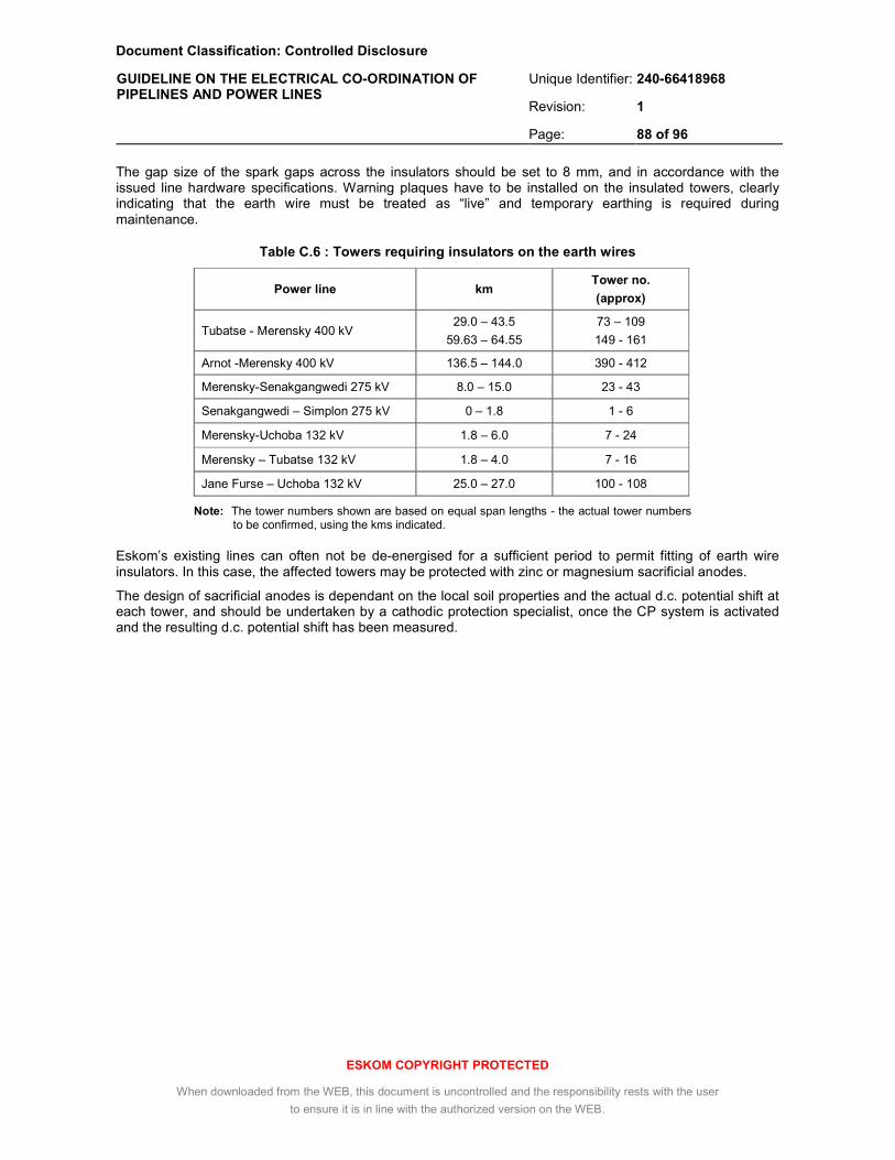
Document Classification: Controlled Disclosure
Unique Identifier: 240-66418968
Revision: 1
GUIDELINE ON THE ELECTRICAL CO-ORDINATION OF PIPELINES AND POWER LINES
Page: 88 of 96
ESKOM COPYRIGHT PROTECTED
When downloaded from the WEB, this document is uncontrolled and the responsibility rests with the user
to ensure it is in line with the authorized version on the WEB.
The gap size of the spark gaps across the insulators should be set to 8 mm, and in accordance with the issued line hardware specifications. Warning plaques have to be installed on the insulated towers, clearly indicating that the earth wire must be treated as “live” and temporary earthing is required during maintenance.
Table C.6 : Towers requiring insulators on the earth wires
Power line km Tower no.
(approx)
Tubatse - Merensky 400 kV 29.0 – 43.5
59.63 – 64.55
73 – 109
149 - 161
Arnot -Merensky 400 kV 136.5 – 144.0 390 - 412
Merensky-Senakgangwedi 275 kV 8.0 – 15.0 23 - 43
Senakgangwedi – Simplon 275 kV 0 – 1.8 1 - 6
Merensky-Uchoba 132 kV 1.8 – 6.0 7 - 24
Merensky – Tubatse 132 kV 1.8 – 4.0 7 - 16
Jane Furse – Uchoba 132 kV 25.0 – 27.0 100 - 108
Note: The tower numbers shown are based on equal span lengths - the actual tower numbers to be confirmed, using the kms indicated.
Eskom’s existing lines can often not be de-energised for a sufficient period to permit fitting of earth wire insulators. In this case, the affected towers may be protected with zinc or magnesium sacrificial anodes.
The design of sacrificial anodes is dependant on the local soil properties and the actual d.c. potential shift at each tower, and should be undertaken by a cathodic protection specialist, once the CP system is activated and the resulting d.c. potential shift has been measured.

Document Classification: Controlled Disclosure
Unique Identifier: 240-66418968
Revision: 1
GUIDELINE ON THE ELECTRICAL CO-ORDINATION OF PIPELINES AND POWER LINES
Page: 89 of 96
ESKOM COPYRIGHT PROTECTED
When downloaded from the WEB, this document is uncontrolled and the responsibility rests with the user
to ensure it is in line with the authorized version on the WEB.
Annex D - Flowchart
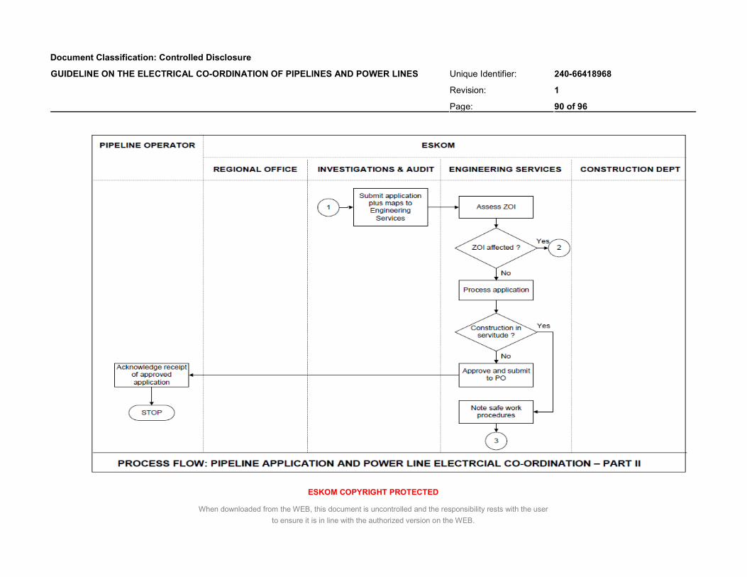
Document Classification: Controlled Disclosure
Unique Identifier: 240-66418968
Revision: 1
GUIDELINE ON THE ELECTRICAL CO-ORDINATION OF PIPELINES AND POWER LINES
Page: 90 of 96
ESKOM COPYRIGHT PROTECTED
When downloaded from the WEB, this document is uncontrolled and the responsibility rests with the user
to ensure it is in line with the authorized version on the WEB.

Document Classification: Controlled Disclosure
Unique Identifier: 240-66418968
Revision: 1
GUIDELINE ON THE ELECTRICAL CO-ORDINATION OF PIPELINES AND POWER LINES
Page: 91 of 96
ESKOM COPYRIGHT PROTECTED
When downloaded from the WEB, this document is uncontrolled and the responsibility rests with the user
to ensure it is in line with the authorized version on the WEB.

Document Classification: Controlled Disclosure
Unique Identifier: 240-66418968
Revision: 1
GUIDELINE ON THE ELECTRICAL CO-ORDINATION OF PIPELINES AND POWER LINES
Page: 92 of 96
ESKOM COPYRIGHT PROTECTED
When downloaded from the WEB, this document is uncontrolled and the responsibility rests with the user
to ensure it is in line with the authorized version on the WEB.

Document Classification: Controlled Disclosure
Unique Identifier: 240-66418968
Revision: 1
GUIDELINE ON THE ELECTRICAL CO-ORDINATION OF PIPELINES AND POWER LINES
Page: 93 of 96
ESKOM COPYRIGHT PROTECTED
When downloaded from the WEB, this document is uncontrolled and the responsibility rests with the user
to ensure it is in line with the authorized version on the WEB.
Annex E – Inspection sheet for a.c. mitigation components and servitude works

Document Classification: Controlled Disclosure
Unique Identifier: 240-66418968
Revision: 1
GUIDELINE ON THE ELECTRICAL CO-ORDINATION OF PIPELINES AND POWER LINES
Page: 94 of 96
ESKOM COPYRIGHT PROTECTED
When downloaded from the WEB, this document is uncontrolled and the responsibility rests with the user
to ensure it is in line with the authorized version on the WEB.

Document Classification: Controlled Disclosure
Unique Identifier: 240-66418968
Revision: 1
GUIDELINE ON THE ELECTRICAL CO-ORDINATION OF PIPELINES AND POWER LINES
Page: 95 of 96
ESKOM COPYRIGHT PROTECTED
When downloaded from the WEB, this document is uncontrolled and the responsibility rests with the user
to ensure it is in line with the authorized version on the WEB.

Document Classification: Controlled Disclosure
Unique Identifier: 240-66418968
Revision: 1
GUIDELINE ON THE ELECTRICAL CO-ORDINATION OF PIPELINES AND POWER LINES
Page: 96 of 96
ESKOM COPYRIGHT PROTECTED
When downloaded from the WEB, this document is uncontrolled and the responsibility rests with the user
to ensure it is in line with the authorized version on the WEB.