Railway Earthing - ERICO Earthing CADWELD® – Earthing Bonds and Earthing Connections for...
12
Railway Earthing CADWELD ® – Earthing Bonds and Earthing Connections for Electrical Railways
-
Upload
trinhkhanh -
Category
Documents
-
view
543 -
download
18
Transcript of Railway Earthing - ERICO Earthing CADWELD® – Earthing Bonds and Earthing Connections for...
Railway EarthingCADWELD® – Earthing Bonds and Earthing
Connections for Electrical Railways
2Ph: 216-351-3060www.erico.com
Introduction
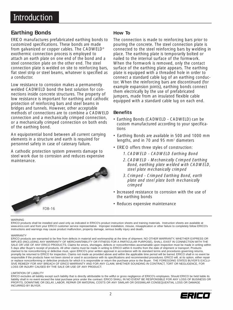
Earthing BondsERICO manufactures prefabricated earthing bonds tocustomized specifications. These bonds are madefrom galvanized or copper cables. The CADWELD®
exothermic connection process is employed toattach an earth plate on one end of the bond and asteel connection plate on the other end. The steelconnection plate is welded on site to reinforcing bars,flat steel strip or steel beams, whatever is specified asa conductor.
Low resistance to corrosion makes a permanentlywelded CADWELD bond the best solution for con-nections inside concrete structures. The property oflow resistance is important for earthing and cathodicprotection of reinforcing bars and steel beams inbridges and tunnels. However, other acceptablemethods of connections are to combine a CADWELDconnection and a mechanically crimped connection,or a mechanically crimped connection on both endsof the earthing bond.
An equipotential bond between all current carryingelements in a structure and earth is required for personnel safety in case of catenary failure.
A cathodic protection system prevents damage tosteel work due to corrosion and reduces expensivemaintenance.
FDB-16
How To The connection is made to reinforcing bars prior topouring the concrete. The steel connection plate is connected to the steel reinforcing bars by welding inplace. The earthing plate is temporarily bolted ornailed to the internal surface of the formwork.When the formwork is removed, only the contactsurface of the earthing plate appears. The earthingplate is equipped with a threaded hole in order toconnect a standard cable lug of an earthing conduc-tor. When the reinforcing bars are discontinued (forexample expansion joints), earthing bonds connectthem electrically by the use of prefabricatedjumpers, made from an insulated flexible cableequipped with a standard cable lug on each end.
Benefits• Earthing Bonds (CADWELD - CADWELD) can be
custom manufactured according to your specifica-tions
• Earthing Bonds are available in 500 and 1000 mmlengths, and in 70 and 95 mm2 diameters
• ERICO offers three styles of construction:
1. CADWELD - CADWELD Earthing Bond2. CADWELD - Mechanically Crimped Earthing
Bond, earthing plate welded with CADWELD,steel plate mechanically crimped
3. Crimped - Crimped Earthing Bond, earthplate and steel plate both mechanicallycrimped
• Increased resistance to corrosion with the use ofthe earthing bonds
• Reduces expensive maintenance
WARNING ERICO products shall be installed and used only as indicated in ERICO’s product instruction sheets and training materials. Instruction sheets are available atwww.erico.com and from your ERICO customer service representative. Improper installation, misuse, misapplication or other failure to completely follow ERICO’sinstructions and warnings may cause product malfunction, property damage, serious bodily injury and death.
WARRANTYERICO products are warranted to be free from defects in material and workmanship at the time of shipment. NO OTHER WARRANTY, WHETHER EXPRESS ORIMPLIED (INCLUDING ANY WARRANTY OF MERCHANTABILITY OR FITNESS FOR A PARTICULAR PURPOSE), SHALL EXIST IN CONNECTION WITH THESALE OR USE OF ANY ERICO PRODUCTS. Claims for errors, shortages, defects or nonconformities ascertainable upon inspection must be made in writing within5 days after Buyer's receipt of products. All other claims must be made in writing to ERICO within 6 months from the date of shipment or transport. Productsclaimed to be nonconforming or defective must, upon ERICO's prior written approval in accordance with its standard terms and procedures governing returns,promptly be returned to ERICO for inspection. Claims not made as provided above and within the applicable time period will be barred. ERICO shall in no event beresponsible if the products have not been stored or used in accordance with its specifications and recommended procedures. ERICO will, at its option, either repairor replace nonconforming or defective products for which it is responsible or return the purchase price to the Buyer. THE FOREGOING STATES BUYER’S EXCLU-SIVE REMEDY FOR ANY BREACH OF ERICO WARRANTY AND FOR ANY CLAIM, WHETHER SOUNDING IN CONTRACT, TORT OR NEGLIGENCE, FORLOSS OR INJURY CAUSED BY THE SALE OR USE OF ANY PRODUCT.
LIMITATION OF LIABILITYERICO excludes all liability except such liability that is directly attributable to the willful or gross negligence of ERICO's employees. Should ERICO be held liable itsliability shall in no event exceed the total purchase price under the contract. ERICO SHALL IN NO EVENT BE RESPONSIBLE FOR ANY LOSS OF BUSINESS ORPROFITS, DOWNTIME OR DELAY, LABOR, REPAIR OR MATERIAL COSTS OR ANY SIMILAR OR DISSIMILAR CONSEQUENTIAL LOSS OR DAMAGEINCURRED BY BUYER.

3
1.1 Connection with the casing
Earthing plates DB-16 can be fastened to the form-work as shown in the following. It has to beensured that the earthing plate and formwork areconnected as closely together as possible. This isachieved by pressing the connection surface of theearthing plate plane-parallel onto the formwork.
1.1.1 The formwork is drilled through and theearthing plate is pulled tightly against theformwork with a bolt M16. Remove thisbolt before removing the formwork.
1.1.2 Connect the earthing plate to the back ofthe formwork with nails using the threeindents. After removing the formwork, cutoff the nail spikes which are sticking out.
1.1.3 For an easy assembly, it is recommended touse a threaded rod with a nut and, depend-ing on the formwork material, with awasher. At first, fasten the threaded rod byhand to the earthing plate, then attach theassembly to the formwork.
1.2. Connection with the reinforcement
The electrically connected conducting rods of thereinforcement, designated as earthing conductor,should have a minimum diameter of 16 mm. Theflat steel plates are connected to these rods by arcwelding. To avoid reduction of the cross sectionalarea, the tracing dimension of the welded seammust be at least 4 mm.
L + L > 90 mm
1. Assembly Instructions
4Ph: 216-351-3060www.erico.com
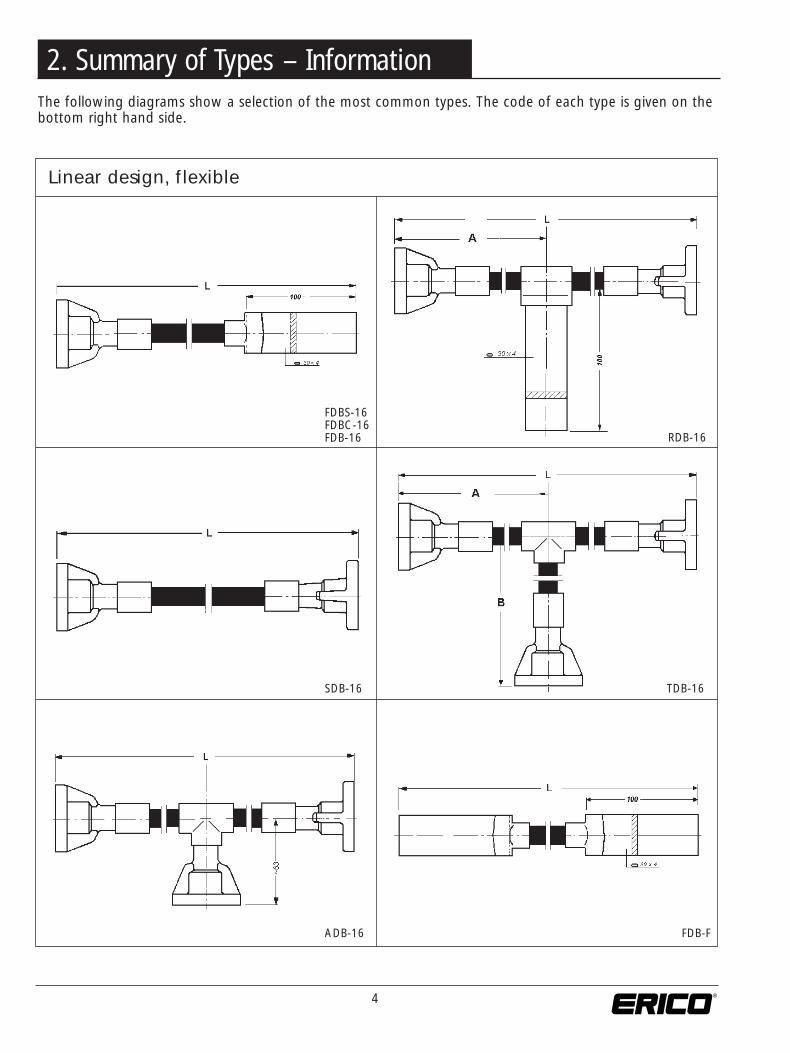
The following diagrams show a selection of the most common types. The code of each type is given on thebottom right hand side.
Linear design, flexible
FDBS-16FDBC-16FDB-16
SDB-16
ADB-16
TDB-16
FDB-F
RDB-16
2. Summary of Types – Information
5
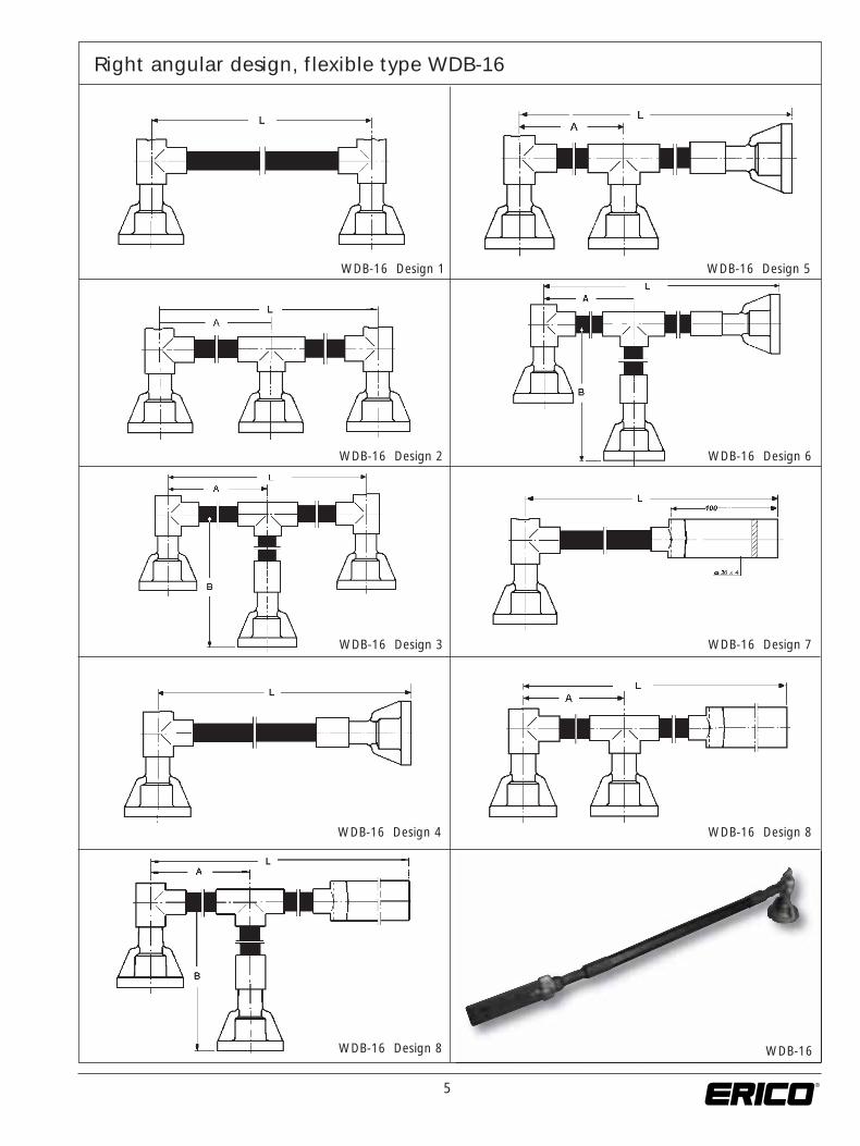
WDB-16 Design 1 WDB-16 Design 5
WDB-16 Design 2 WDB-16 Design 6
WDB-16 Design 3 WDB-16 Design 7
WDB-16 Design 4 WDB-16 Design 8
WDB-16 Design 8
Right angular design, flexible type WDB-16
WDB-16
6Ph: 216-351-3060www.erico.com
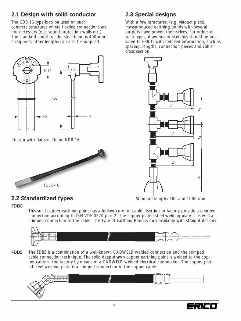
2.1 Design with solid conductorThe KDB 16 type is to be used on such concrete structures where flexible connections arenot necessary (e.g. sound protection walls etc.). The standard length of the steel band is 400 mm.If required, other lengths can also be supplied.
Design with flat steel band KDB-16
2.3 Special designsWith a few structures, (e.g. viaduct piers),massproduced earthing bonds with several outputs have proven themselves. For orders ofsuch types, drawings or sketches should be pro-vided to ERICO with detailed information, such asspacing, lengths, connection pieces and cablecross section.
2.2 Standardized types Standard lengths 500 and 1000 mm
FDBCThis solid copper earthing point has a hollow core for cable insertion to factory-provide a crimpedconnection according to DIN VDE 0220 part 2. The copper plated steel welding plate is as well acrimped connection to the cable. This type of Earthing Bond is only available with straight designs.
FDBS The FDBS is a combination of a well-known CADWELD welded connection and the crimpedcable connection technique. The solid deep-drawn copper earthing point is welded to the cop-per cable in the factory by means of a CADWELD welded electrical connection. The copper plat-ed steel welding plate is a crimped connection to the copper cable.
FDBC-16

7
FD
B-1
6S
DB
-16
WD
B-1
6D
esig
n 1
TD
B-1
6E
DB
-16
WD
B-1
6D
esig
n 2
KD
B-1
6K
DB
/FF
-16
FD
B-F
WD
B-1
6D
esig
n 4
KD
B-1
6S
peci
al D
esig
nW
DB
-16
Des
ign
7
FD
BC
-16
FD
BS
-16
Line
ar c
onne
ctio
n D
B16
cab
leN
YY-
0
Ang
ular
con
nect
ion
DB
16 c
able
NY
Y- 0
Sym
bol
Desig
natio
nAp
plica
tion
Earth
bon
d co
nstru
ctio
n 1
(l >
25K
A)
Cons
t. 1(
l< 2
5 kA
)
Cons
tr. 2
(l >
25K
A)
cons
istin
g of
a c
able
NYY
- 0 1
x70
mm≤
Earth
ing
plat
e DB
16
weld
ed
ÿ 5
0 / M
16
ÿ
50
/ M16
wi
th w
elde
d-on
ear
thin
g pl
ate
DB 1
6 an
d or
wel
ding
tong
ue
Wel
ding
tong
ue L
. 100
mm
30 X
4 m
m
40
X 5
mm
Ea
rthin
g bo
nds
of c
onst
ruct
ion
2 (lk
> 2
5KA)
Cabl
e NY
Y- 0
70
mm≤
95
mm≤
cons
istin
g of
a c
able
NYY
- 0 1
y95
mm≤
Com
pres
sed
earth
ing
plat
e DB
16
ÿ 5
0 / M
16
ÿ
50 /
M16
with
wel
ded-
on e
arth
ing
plat
e DB
16
and
or w
eldi
ng to
ngue
Com
pres
sed
weld
ing
tong
ue6
X 25
mm
.8 x
31
mm
The
norm
al le
ngth
of t
he w
eldi
ng to
ngue
is 1
00 m
m.
With
ear
thin
g lin
ks o
f con
stru
ctio
n 1
and
2 al
l ear
thin
g pl
ate
The
leng
th is
give
n se
para
tely
conn
ectio
ns (w
elde
d on
or p
ress
ed) a
nd th
e co
mpr
esse
de.
g. w
ith 4
00 m
m. F
or K
DB- 1
6 wi
th le
ngth
L a
s re
quire
d by
KDB
/ FF-
16.
weld
ing
tong
ues
are
shea
thed
with
hea
t-shr
ink
sleev
ing
Type
KD
B-
16Ty
pe F
DB
- 16
Type
WD
B-
16Ty
pe W
DB
- 16
des
ign
Ang
ular
con
nect
ion
DB
16
with
wel
ding
ton
gue
Line
ar c
onne
ctio
n D
B 1
6 w
ith c
able
NY
Y- 0
Ang
ular
con
nect
ion
DB
16
with
cab
le N
YY-
0T-
con
nect
ion
DB
16
with
cab
le N
YY-
0
Ord
erin
g ex
ampl
e:
... p
iece
s TD
B -
16...
pie
ces
SD
B -
16...
pie
ces
FDB
C -
16...
pie
ces
FDB
SD
- 16
Spec
ial d
esig
nsC
onst
ruct
ion
1C
onst
ruct
ion
2C
onst
ruct
ion
1C
onst
ruct
ion
2on
ly a
ccor
ding
L =
2000
mm
L =
500
mm
L =
500
mm
L =
1000
mm
to a
ske
tch
A =
100
0 m
mB
= 3
00 m
m
For
con
stru
ctio
n 1
For
con
stru
ctio
n 2
Conn
ectio
n DB
16- c
able
NYY
- 0Co
nnec
tion
DB16
- cab
le N
YY- 0
Con
nect
ion:
cabl
e N
YY-
0 7
06X
25 s
teel
cabl
e N
YY-
0 9
58X
31 s
teel
Wel
d se
am
Wel
ding
to s
teel
re
info
rcem
ent
Usa
ble
for:
Ove
rhea
d lin
e re
gula
tions
of
the
DB
3 E
bs. 1
5.03
.19
BL.
1S
een
Fran
kfur
t/Mai
nTZ
F 73
on
Issu
eD
ate
Sca
leD
imen
sion
s w
ithou
tre
fere
nce
to to
lera
nce
Dat
e
Nam
eS
umm
ary
of t
ypes
of
CA
DW
ELD
Ear
thin
g B
onds
Revis
er
08-
03-
200
Di
ngem
ans
Chec
ked
08-
03-
200
F.
from
Erp
Stan
dard
Plan
chk
.
1 S
heet
Cros
s Sec
tion
V
iew
Da
te
N
ame
Re
sp. C
hang
e Date
Nam
e Orig
. 3 C
D 10
1.180
d
Rep
l. for
3Ebs
. 15.
0319
/ 07.
99
Rep
l. by B
Leng
th
L pe
r sid
em
in. 4
5 m
m
8Ph: 216-351-3060www.erico.com
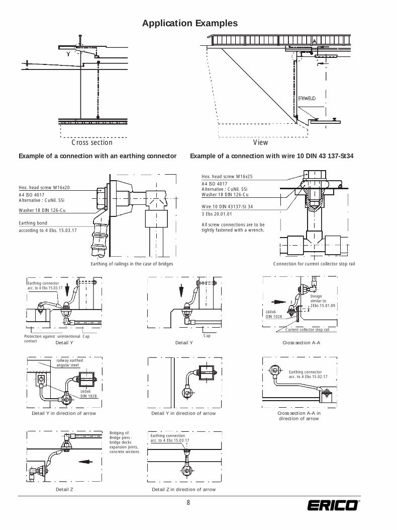
Cross section View
Example of a connection with an earthing connector Example of a connection with wire 10 DIN 43 137-St34
Hex. head screw M16x20
A4 ISO 4017Alternative : CuNil. 5Si
Washer 18 DIN 126-Cu
Earthing bond
according to 4 Ebs. 15.03.17
Hex. head screw M16x25
A4 ISO 4017Alternative : CuNil. 5SiWasher 18 DIN 126-Cu
Wire 10 DIN 43137-St 34
3 Ebs 20.01.01
All screw connections are to be tightly fastened with a wrench.
Earthing of railings in the case of bridges Connection for current collector stop rail
Earthing connectoracc. to 4 Ebs 15.03.17
Design similar to 2Ebs 15.01.09
L60x6DIN 1028
Protection against unintentionalcontact
Cap Cap
Current collector stop rail
Detail Y Detail Y Cross section A-A
Detail Y in direction of arrow Detail Y in direction of arrow Cross section A-A in direction of arrow
Earthing connectoracc. to 4 Ebs 15.02.17
railway earthedangular steel
L60x6DIN 1028
Bridging of:Bridge piers - bridge decksexpansion joints, concrete sections
Detail Z Detail Z in direction of arrow
Earthing connectionacc. to 4 Ebs 15.03.17
Application Examples
9
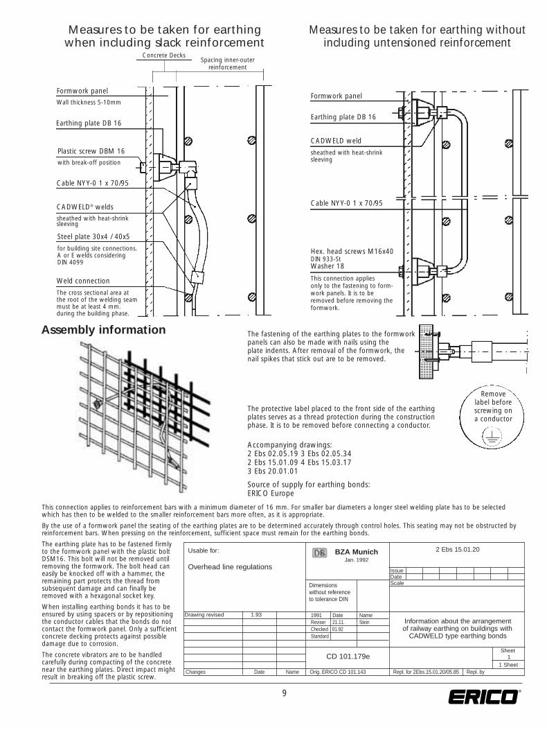
Measures to be taken for earthingwhen including slack reinforcement
Measures to be taken for earthing without including untensioned reinforcement
Formwork panel
Wall thickness 5-10mmFormwork panel
Earthing plate DB 16Earthing plate DB 16
Concrete DecksSpacing inner-outer
reinforcement
CADWELD weld
sheathed with heat-shrink sleeving
Plastic screw DBM 16
with break-off position
Cable NYY-0 1 x 70/95
Cable NYY-0 1 x 70/95
CADWELD® welds
sheathed with heat-shrink sleeving
Steel plate 30x4 / 40x5
for building site connections.A or E welds consideringDIN 4099
Hex. head screws M16x40DIN 933-StWasher 18
This connection applies only to the fastening to form- work panels. It is to beremoved before removing theformwork.
Weld connection
The cross sectional area at the root of the welding seam must be at least 4 mm. during the building phase.
Assembly information
Remove label before screwing on a conductor
The fastening of the earthing plates to the formworkpanels can also be made with nails using theplate indents. After removal of the formwork, thenail spikes that stick out are to be removed.
The protective label placed to the front side of the earthingplates serves as a thread protection during the constructionphase. It is to be removed before connecting a conductor.
Accompanying drawings:2 Ebs 02.05.19 3 Ebs 02.05.342 Ebs 15.01.09 4 Ebs 15.03.173 Ebs 20.01.01
Source of supply for earthing bonds:ERICO Europe
This connection applies to reinforcement bars with a minimum diameter of 16 mm. For smaller bar diameters a longer steel welding plate has to be selectedwhich has then to be welded to the smaller reinforcement bars more often, as it is appropriate.
By the use of a formwork panel the seating of the earthing plates are to be determined accurately through control holes. This seating may not be obstructed byreinforcement bars. When pressing on the reinforcement, sufficient space must remain for the earthing bonds.
The earthing plate has to be fastened firmlyto the formwork panel with the plastic boltDSM16. This bolt will not be removed untilremoving the formwork. The bolt head caneasily be knocked off with a hammer, theremaining part protects the thread fromsubsequent damage and can finally beremoved with a hexagonal socket key.
When installing earthing bonds it has to beensured by using spacers or by repositioningthe conductor cables that the bonds do notcontact the formwork panel. Only a sufficientconcrete decking protects against possibledamage due to corrosion.
The concrete vibrators are to be handledcarefully during compacting of the concretenear the earthing plates. Direct impact mightresult in breaking off the plastic screw.
Usable for:
Overhead line regulations
2 Ebs 15.01.20BZA MunichJan. 1992
IssueDateScaleDimensions
without reference to tolerance DIN
1991 Date NameInformation about the arrangement of railway earthing on buildings with
CADWELD type earthing bonds
Reviser 21.11. SteinChecked 01.92 Standard
Sheet1
Changes Date Name Orig. ERICO CD 101.143 Repl. for 2Ebs.15.01.20/05.85 Repl. by
Drawing revised 1.93
CD 101.179e1 Sheet
10Ph: 216-351-3060www.erico.com
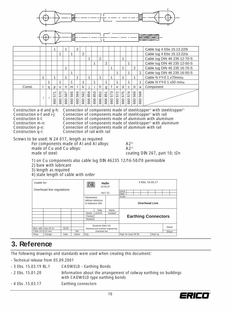
Construction a-d and g-h: Connection of components made of steel/copper1) with steel/copper1)
Construction e-f and i-j: Connection of components made of steel/copper1) with railConstruction k-l: Connection of components made of aluminum with aluminumConstruction m-n: Connection of components made of steel/copper1) with aluminumConstruction p-o: Connection of components made of aluminum with railConstruction q-r: Connection of rail with rail
Screws to be used: N 24 017, length as requiredFor components made of Al and Al alloys: A22)
made of Cu and Cu alloys: A22)
made of steel: coating DIN 267, part 10; tZn
1) on Cu components also cable lug DIN 46235 12/16-50/70 permissible2) bare with lubricant3) length as required4) state length of cable with order
1 1 2 Cable lug 4 Ebs 15.13.22/b1 1 2 Cable lug 4 Ebs 15.13.22/a
1 2 1 Cable lug DIN 46 235 12-70-S1 2 1 Cable lug DIN 46 235 12-50-S
1 1 1 2 Cable lug DIN 46 235 16-70-S1 1 1 2 Cable lug DIN 46 235 16-50-S
1 1 1 1 1 1 1 1 1 Cable N YY-0 1 x70mm≥1 1 1 1 1 1 1 1 1 Cable N YY-0 1 x50 mm≥
Const. r q p o n m l k j i h g f e d c b a Component
– –
660
571
660
570
660
567
660
565
660
564
660
562
666
854
666
853
666
852
666
851
660
573
660
572
660
575
660
574
660
569
660
568
The following drawings and standards were used when creating this document:
- Technical release from 05.09.2001
- 3 Ebs. 15.03.19 BL.1 CADWELD - Earthing Bonds
- 2 Ebs. 15.01.20 Information about the arrangement of railway earthing on buildings with CADWELD type earthing bonds
- 4 Ebs .15.03.17 Earthing connectors
Usable for:
Overhead line regulations
4 Ebs. 15.03.17Halle20.05.97
NGT 52IssueDateScaleDimensions
without reference to tolerance DIN
Date Name
Earthing ConnectorsReviser 19.05.97 KurzbachChecked Standard
Sheet
Resp. Change Date Name Orig. Repl. for issue 09 95 Repl. by
Deutsche Bahn AGElectrical and machine engineering
Overhead line SheetBem. with cross ref. to 03.003 Ebs 15.02.01 rem. Gla
Overhead Line
3. Reference

11
We reserve the right to make changes to the information given in this brochure where we think that the changes are necessary oradvantageous. This brochure gives only introductory information about products and services. It is not a constituent part of a contract.The company is not liable for loss or damage arising from non-compliance with the instructions or with different products.
Deutsche BahnResearch and Technology CentreOverhead linesTheodor-Heuss-Allee 760486 Frankfurt am Main
Publication: EBA Report 22TEL Frankfurt/MainTEL 2 MunichTZF 73 Frankfurt/Main
ERICO GmbH
Technical Release1. The present technical release applies to the company
ERICO GmbH66851 Schwanenmühle
2. The technical release applies to the supply of the following equipment to the DB AG:
FDBC-16 earthing bondsFDBS-16 earthing bonds
3. The following documentation, test certificates and other details were checked, and form the basis of the technical release:
- EBA authorization for electronic systems no.: 201090/8- Investigation of the short circuit behavior, Report no.: 98471638.000-HVL
99-1322, of the KEMA Netherlands B.V.- Separation testing by the company ERICO, Test report no.: PN0023T1- Drawing 3 Ebs 15.03.19 Sht. 1
4. Additional condition:
5. The technical release presented is valid until revoked.
Frankfurt/Main, 05.09.2001
(Dipl.-Ing. Borgwardt)
Copyright ©2002, 2009, 2010 ERICO International Corporation. All rights reserved.CADDY, CADWELD, CRITEC, ERICO, ERIFLEX, ERITECH, and LENTON are registered trademarks of ERICO International Corporation. R407B-WWEN R1609LT09WWEN 02M1010
AUSTRALIAPhone 1-800-263-508Fax 1-800-423-091
BELGIUMPhone 0800-757-48Fax 0800-757-60
CANADAPhone +1-800-677-9089Fax +1-800-677-8131
CHILEPhone +56-2-370-2908Fax +56-2-369-5657
DENMARKPhone 808-89-372Fax 808-89-373
FRANCEPhone 0-800-901-793Fax 0-800-902-024
GERMANYPhone 0-800-189-0272Fax 0-800-189-0274
HONG KONGPhone +852-2764-8808Fax +852-2764-4486
HUNGARYPhone 06-800-16538Fax +39-0244-386-107
INDONESIAPhone +62-21-575-0941Fax +62-21-575-0942
ITALYPhone 800-870-938Fax 800-873-935
MEXICOPhone +52-55-5260-5991Fax +52-55-5260-3310
NETHERLANDSPhone 0800-0200-135Fax 0800-0200-136
NORWAYPhone 800-100-73Fax 800-100-66
SINGAPOREPhone +65-6-268-3433Fax +65-6-268-1389
SPAINPhone 900-993-154Fax 900-807-333
SWEDENPhone 020-790-908Fax 020-798-964
SWITZERLANDPhone 0800-55-86-97Fax 0800-55-96-15
THAILANDPhone +66-2-267-5776Fax +66-2-636-6988
UNITED KINGDOMPhone 0808-2344-670Fax 0808-2344-676
UNITED STATESPhone 1-800-753-9221Fax +1-440-248-0723
POLANDPhone +48-71-349-04-60Fax +48-71-349-04-61
BRAZILPhone +55-11-3623-4333Fax +55-11-3621-4066
www.erico.com
CHINAPhone +86-21-3430-4878 Fax +86-21-5831-8177
UNITED ARABEMIRATESPhone +971-4-881-7250Fax +971-4-881-7270