TITLE : SALT Telescope Control System (TCS) Specification · Telescope (SALT) Telescope Control...
51
TCS Specification Doc No. SALT1700AS0001 Issue A 1 APPROVAL SHEET TITLE : SALT Telescope Control System (TCS) Specification DOCUMENT NUMBER : 1000AS0007 ISSUE: A SYNOPSIS : This document describes the technical requirements for the SALT TCS. It defines the functional, operational, software and hardware requirements that must be met. KEYWORDS : Telescope Control System, Integrated control system, Telescope Software, Telescope Operator PREPARED BY : Gerhard Swart APPROVED : Leon Nel TCS PROJECT MANAGER Kobus Meiring SALT PROJECT MANAGER DATE : March 2001
Transcript of TITLE : SALT Telescope Control System (TCS) Specification · Telescope (SALT) Telescope Control...

TCS Specification
Doc No. SALT1700AS0001 Issue A
1
APPROVAL SHEET
TITLE : SALT Telescope Control System (TCS) Specification
DOCUMENT NUMBER : 1000AS0007 ISSUE: A
SYNOPSIS : This document describes the technical requirements for theSALT TCS. It defines the functional, operational, softwareand hardware requirements that must be met.
KEYWORDS : Telescope Control System, Integrated control system,Telescope Software, Telescope Operator
PREPARED BY : Gerhard Swart
APPROVED :Leon NelTCS PROJECT MANAGER
Kobus MeiringSALT PROJECT MANAGER
DATE : March 2001
TCS Specification
Doc No. SALT1700AS0001 Issue A
2
This issue is only valid when the above signatures are present.
TCS Specification
Doc No. SALT1700AS0001 Issue A
3
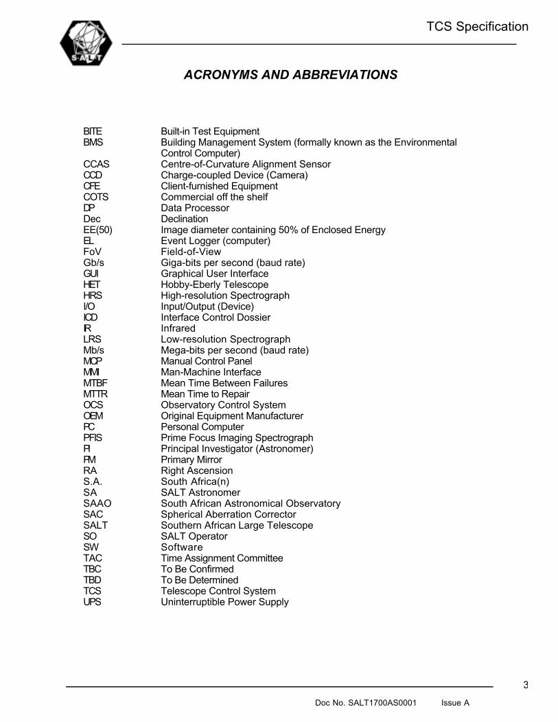
ACRONYMS AND ABBREVIATIONS
BITE Built-in Test EquipmentBMS Building Management System (formally known as the Environmental
Control Computer)CCAS Centre-of-Curvature Alignment SensorCCD Charge-coupled Device (Camera)CFE Client-furnished EquipmentCOTS Commercial off the shelfDP Data ProcessorDec DeclinationEE(50) Image diameter containing 50% of Enclosed EnergyEL Event Logger (computer)FoV Field-of-ViewGb/s Giga-bits per second (baud rate)GUI Graphical User InterfaceHET Hobby-Eberly TelescopeHRS High-resolution SpectrographI/O Input/Output (Device)ICD Interface Control DossierIR InfraredLRS Low-resolution SpectrographMb/s Mega-bits per second (baud rate)MCP Manual Control PanelMMI Man-Machine InterfaceMTBF Mean Time Between FailuresMTTR Mean Time to RepairOCS Observatory Control SystemOEM Original Equipment ManufacturerPC Personal ComputerPFIS Prime Focus Imaging SpectrographPI Principal Investigator (Astronomer)PM Primary MirrorRA Right AscensionS.A. South Africa(n)SA SALT AstronomerSAAO South African Astronomical ObservatorySAC Spherical Aberration CorrectorSALT Southern African Large TelescopeSO SALT OperatorSW SoftwareTAC Time Assignment CommitteeTBC To Be ConfirmedTBD To Be DeterminedTCS Telescope Control SystemUPS Uninterruptible Power Supply

TCS Specification
Doc No. SALT1700AS0001 Issue A
4
DEFINITIONS
Acquisition time This is the length of time required to put the target at adesired position (a bore-sight), within the offset pointingrequirement, from end-of-slew, until start of theintegration
Cost baseline This is the design baseline at the end of the conceptstudy, which was used to determine the cost of theSALT project, and on which the budget is based. It iscontained in the “SALT Report of Interim Project Team,April 1999”.
Growth Path This includes concepts that have not been fully explored,and do not form part of the deliverable. However, theseconcepts have to form part of the decision makingprocess in reaching the Technical or Cost Baselines.
Technical Baseline This is the design baseline that is required to fulfil therequirements of the SALT Observatory ScienceRequirements, Issue 7.1, and is the topic of thisSpecification. This baseline has not been costed, and thebudget implications will have to be ratified by the SALTBoard.

TCS Specification
Doc No. SALT1700AS0001 Issue A
5
TABLE OF CONTENTS
1 Scope ..........................................................................................................91.1 Identification..................................................................................................................................91.2 System overview..........................................................................................................................9
2 Referenced documents ...........................................................................103 Customer Furnished Equipment and Responsibilities ........................114 Functional Requirements........................................................................124.1 Functional definition...................................................................................................................124.1.1 Operational Concept.................................................................................................................124.1.2 Functional Diagrams.................................................................................................................12
4.1.2.1 Timeline Diagram...................................................................................................................124.1.2.2 System States ......................................................................................................................124.1.2.3 Functional Flow Diagram ......................................................................................................15
4.1.3 Process....................................................................................................................................174.1.3.1 Phases One and Two...........................................................................................................174.1.3.2 Phase Three .........................................................................................................................174.1.3.3 Phase Four ...........................................................................................................................174.1.3.4....................................................................................................................................................18
5 System Technical Requirements............................................................185.1 Schematic diagram.....................................................................................................................185.2 TCS Interfaces.............................................................................................................................205.2.1 External Interfaces...................................................................................................................205.2.2 Internal Interfaces ....................................................................................................................215.3 Characteristics............................................................................................................................225.3.1 Performance.............................................................................................................................22
5.3.1.1 Communication......................................................................................................................225.3.1.2 Configurable MMI ..................................................................................................................225.3.1.3 User-Configured commands.................................................................................................225.3.1.4 Operator task times ..............................................................................................................225.3.1.5 Information Display Integration.............................................................................................23
5.3.2 Physical Characteristics...........................................................................................................245.3.2.1 Location................................................................................................................................245.3.2.2 Telescope Axis System........................................................................................................24
5.3.3 Environmental Requirements....................................................................................................255.3.3.1 Normal Operational Environment...........................................................................................255.3.3.2 Survival Environment............................................................................................................25
5.4 Operation and Maintenance Requirements ..........................................................................265.4.1 Packaging, handling, storage ...................................................................................................265.4.2 Product Documentation ............................................................................................................265.4.3 Personnel and Training.............................................................................................................26
5.4.3.1 Operation..............................................................................................................................265.4.3.2 Maintenance .........................................................................................................................26
5.4.4 Availability ................................................................................................................................275.4.5 Test Equipment and Tools ........................................................................................................27
5.4.5.1 Interface Management Tool ..................................................................................................275.4.5.2 Data monitoring tool ..............................................................................................................27
5.5 Design and Construction constraints ....................................................................................28

TCS Specification
Doc No. SALT1700AS0001 Issue A
6
5.5.1 General design guidelines and constraints..............................................................................285.5.2 Materials, Processes and Parts ...............................................................................................285.5.3 Electromagnetic Radiation ........................................................................................................295.5.4 Workmanship............................................................................................................................295.5.5 Interchangeability .....................................................................................................................295.5.6 Safety.......................................................................................................................................29
5.5.6.1 Safety-critical failures ..........................................................................................................295.5.6.2 Software safety...................................................................................................................295.5.6.3 Safe initialisation...................................................................................................................295.5.6.4 Emergency Stop ...................................................................................................................295.5.6.5 Enhancement of operator awareness .................................................................................29
5.5.7 Ergonomics...............................................................................................................................295.5.8 Special commissioning requirements .......................................................................................30
5.5.8.1 Subsystem MMI’s..................................................................................................................305.5.8.2 Test Points............................................................................................................................305.5.8.3 Test Data ..............................................................................................................................30
5.5.9 Software..................................................................................................................................305.5.10 Computer Hardware.................................................................................................................305.5.11 Electrical Design.......................................................................................................................30
5.5.11.1 UPS ...................................................................................................................................305.5.11.2 Standby Power generators ..............................................................................................30
5.5.12 Data security............................................................................................................................315.5.13 Future growth ..........................................................................................................................31
5.5.13.1 Phasing .............................................................................................................................315.5.13.2 Improved optical performance ..........................................................................................315.5.13.3 IR PFIS...............................................................................................................................315.5.13.4 Remote Observing ............................................................................................................315.5.13.5 Additional Instruments.......................................................................................................315.5.13.6 Data Mirror off-site............................................................................................................32
6 Subsystem Technical Requirements .....................................................336.1 Major Component List...............................................................................................................336.2 Subsystem Characteristics......................................................................................................346.2.1 SO Workstation ........................................................................................................................34
6.2.1.1 Hardware .............................................................................................................................346.2.1.2 Standard Software...............................................................................................................346.2.1.3 Custom Software .................................................................................................................34
6.2.2 SA Workstation ........................................................................................................................376.2.2.1 Hardware .............................................................................................................................376.2.2.2 Standard Software...............................................................................................................376.2.2.3 Custom Software .................................................................................................................386.2.2.4 Data Reduction PC requirements for the SA ........................................................................40
6.2.3 Data Processor ........................................................................................................................406.2.3.1 Hardware .............................................................................................................................416.2.3.2 Standard Software...............................................................................................................416.2.3.3 Custom Software .................................................................................................................41
6.2.4 TCS Server...............................................................................................................................416.2.4.1 Hardware .............................................................................................................................416.2.4.2 Standard Software...............................................................................................................416.2.4.3 Custom Software .................................................................................................................41
6.2.5 Manual Control Panel................................................................................................................43
TCS Specification
Doc No. SALT1700AS0001 Issue A
7
6.2.5.1 Hardware .............................................................................................................................436.2.5.2 Standard Software...............................................................................................................436.2.5.3 Custom Software .................................................................................................................43
6.2.6 Event Logger............................................................................................................................436.2.6.1 Hardware .............................................................................................................................436.2.6.2 Standard Software...............................................................................................................446.2.6.3 Custom Software .................................................................................................................44
6.2.7 Ancillary Equipment..................................................................................................................446.2.7.1 Precision time source ...........................................................................................................446.2.7.2 Printers .................................................................................................................................446.2.7.3 Interlock Panel.......................................................................................................................446.2.7.4 Network hubs, routers and cables.......................................................................................456.2.7.5 Alignment Equipment.............................................................................................................45
7 Test Requirements...................................................................................467.1 Verification cross-reference Matrix.......................................................................................467.2 Detailed Test Methods ..............................................................................................................46
8 Notes.........................................................................................................47
Appendix A: SO Display InformationAppendix B: SA Display InformationAppendix C: Common Display InformationAppendix D: List of TBD’s and TBC’s

TCS Specification
Doc No. SALT1700AS0001 Issue A
8
Modification History
Revision Changes Pages effectedA New Document All

TCS Specification
Doc No. SALT1700AS0001 Issue A
9
1 Scope
1.1 Identification
This document specifies the requirements (the Technical Baseline) for the Southern African LargeTelescope (SALT) Telescope Control System (TCS). It is an internal document that will be used toguide the TCS development and to test the TCS against.
SALT is a reflecting optical astronomical telescope of the tilted Arecibo type, based on the design ofthe HET. The TCS forms the integrating node of the telescope and provides the Man-Machine Interface(MMI) to the SALT Operator (SO), the SALT Astronomer (SA) and the Principal Investigator (PI).
In general, the word “shall” is used to indicate mandatory requirements while descriptive statementsare used to provide non-mandatory information.
1.2 System overview
The TCS performs the integrating function of SALT by controlling the interaction between thesubsystems, presenting the SO and SA with relevant information and responding to their commands.Computers linked to the subsystems via a computer network implement the functions of the TCS.
The TCS also includes the observation planning and scheduling tools, fault reporting and logging,hereafter referred to as the Observatory Control System (OCS). SALT planning and budgets (costbaseline) exclude the OCS but where possible, these have been specified in this document. In orderto optimise the use of available funding and time, TCS requirements that could be postponed until afterFirst Light have been indicated in italics.
The TCS excludes all control functions related to any Science Instrumentation. A measure ofinformation integration with the Science Instrumentation is anticipated and the SA workstation will bedesigned to allow client/server operation with the Instrument Computers.
Issue A of this document addresses primarily the TCS control functions (i.e. those not forming part ofthe OCS) and the associated Man Machine Interfaces.
TCS Specification
Doc No. SALT1700AS0001 Issue A
10
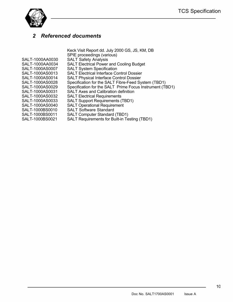
2 Referenced documents
Keck Visit Report dd. July 2000 GS, JS, KM, DBSPIE proceedings (various)
SALT-1000AA0030 SALT Safety AnalysisSALT-1000AA0034 SALT Electrical Power and Cooling BudgetSALT-1000AS0007 SALT System SpecificationSALT-1000AS0013 SALT Electrical Interface Control DossierSALT-1000AS0014 SALT Physical Interface Control DossierSALT-1000AS0028 Specification for the SALT Fibre-Feed System (TBD1)SALT-1000AS0029 Specification for the SALT Prime Focus Instrument (TBD1)SALT-1000AS0031 SALT Axes and Calibration definitionSALT-1000AS0032 SALT Electrical RequirementsSALT-1000AS0033 SALT Support Requirements (TBD1)SALT-1000AS0040 SALT Operational RequirementSALT-1000BS0010 SALT Software StandardSALT-1000BS0011 SALT Computer Standard (TBD1)SALT-1000BS0021 SALT Requirements for Built-in Testing (TBD1)

TCS Specification
Doc No. SALT1700AS0001 Issue A
11
3 Customer Furnished Equipment and Responsibilities
The Science Instruments and their computers are outside the scope of the Telescope project. Thesesystems and their MMI/interface software are “Customer Furnished Equipment”.
Details of the data and functional interfacing will be agreed and documented in the SALT InterfaceControl Dossier and each instrument’s own specification.
The data connection to the existing data network at Sutherland and the Internet, though not CFE, willrequire close liaison with the SAAO.

TCS Specification
Doc No. SALT1700AS0001 Issue A
12
4 Functional Requirements
4.1 Functional definition
4.1.1 Operational Concept
The SALT operational concept is defined in the “SALT Operational Requirement” document listed insection 2. The TCS will provide information to and receive instructions from the SALT Operator,SALT Astronomer, Principal Investigator and the maintenance personnel. The TCS will also storeand distribute that data as required.
The TCS comprises a network of computers that together perform the desired functions.
Initially the SA and SO will operate the telescope from the SALT control room at the telescope butthe design shall facilitate moving this to Cape Town at a later stage.
The PI may be located anywhere in the world and has limited interaction with the TCS across theInternet.
The maintenance staff will perform operational and maintenance tasks from various positionsinside the telescope but the design shall facilitate also doing this from Cape Town at a later stage.
Science data will be stored on a data processor from which the PI will retrieve the data via FTPand/or CD-ROM.
4.1.2 Functional Diagrams
4.1.2.1 TIMELINE DIAGRAM
Timelines of the operation can be found in the SALT Operational Requirement.
4.1.2.2 SYSTEM STATES
4.1.2.2.1 TCS Control States
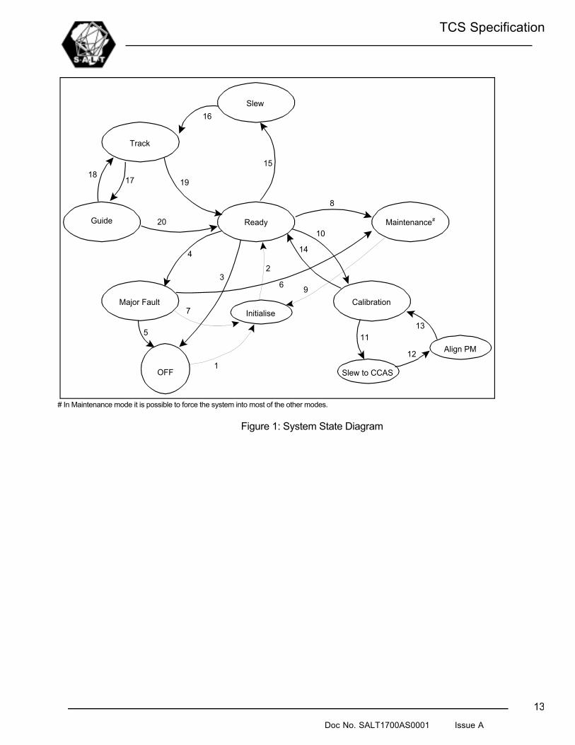
Figure 1 below defines the anticipated control states of the Telescope System and will becontrolled by the TCS Server. Each of the modes are defined in the paragraphs that followwhile the conditions for state transitions are defined in Table 1. Final modes and states willbe determined during the software design.
4.1.2.2.2 OCS States
The non TCS-server functions may have specific states but these will be determined duringthe design phase and are not defined here.
TCS Specification
Doc No. SALT1700AS0001 Issue A
13
Ready
Slew
Track
Guide
Major Fault Calibration
Maintenance#
OFF Slew to CCAS
Align PM
1
23
6
11
12
13
14
16
1718
9
10
5
15
19
Initialise
4
7
8
20
# In Maintenance mode it is possible to force the system into most of the other modes.
Figure 1: System State Diagram

TCS Specification
Doc No. SALT1700AS0001 Issue A
14
Initial State Next State Event triggering the change of state1 Off Initialise Electrical power turned ON2 Initialise Ready Initialisation complete or initialisation time-out3 Ready Off System Shut-down command issued or power turned OFF4 Ready Major Fault Major System Fault detected7 Major Fault Initialise Major System Fault recovers or is reset5 Major Fault Off System Shut-down command issued or power turned OFF6 Major Fault Maintenance Operator selects Maintenance mode while Major Fault8 Ready Maintenance Operator selects Maintenance mode while system Ready9 Maintenance Initialise Operator Quits Maintenance mode10 Ready Calibrate Operator selects Calibrate mode11 Calibrate Slew to CCAS Operator selects Primary Mirror Alignment mode12 Slew CCAS Align PM Structure and Tracker reach desired destination for PM
alignment13 Align PM Calibrate Primary Mirror Alignment completed or aborted14 Calibrate Ready Operator Quits Set-up mode15 Ready Slew Operator commands system to Acquire an object16 Slew Track Object Acquired17 Track Guide Guidance object selected and guidance enabled18 Guide Track Guidance discontinued19 Track Ready Tracking discontinued or operator commands system to
acquire new object20 Guide Ready Operator commands system to acquire new object
Table 1: System State Transition Requirements
OFF: This is the state of the telescope when the power to all devices is OFF. In this state, thetelescope shall be safe.INITIALISE: This is a transitional state during which all the subsystems initialise to a known state. TheTCS server monitors the initialisation of each subsystem and moves to the ready state when all thesubsystems are initialised or after a pre-defined time-out.READY: This is the default state of the telescope. During this state all systems are stationary butready to enter into any other valid state. Non-intrusive adjustments and configuration of the systemcan be made in this state. Manual control of any subsystem is allowed in this state provided that it isauthorised by the TCS server and does not interfere with other subsystems. Ventilation isautomatically controlled in this state, to the appropriate program (i.e. Day or Night).SLEW: In this transitional state the TCS server sends commands to lift the Structure, rotate it to thedesired azimuth angle and to put down again. The Dome follows the structure rotation and the Trackermoves to the desired X, Y, Z, Phi, Theta and Rho angle. During normal operation, the system willautomatically proceed to the TRACK state upon reaching the pointing destination.TRACK: The structure is stationary on the pier, the dome is stationary, and the tracker is moving in allits degrees of freedom while tracking a celestial object. Tracking is open-loop assuming that theobject is moving at the programmed rate. The object is acquired in the Acquisition camera, a guidanceobject selected and the light directed at the science instrument.GUIDE: Closed-loop tracking using the selected guidance object is done in this mode. Manual guidanceoffsets can be entered by the operator or automatic offsets can be received from the scienceinstrument. Disengaging the guidance returns the system to the TRACK mode.MAINTENANCE: In this state, the user has full control of the system although warnings shall beissued before potentially dangerous actions are performed. In this state intrusive adjustments can bemade to the system (e.g. actuator calibrations, software downloads etc). Any transition from thismode shall be accompanied by system re-initialisation to bring the system to a known condition. It shallbe possible to “force” the system and each subsystem into any of the other system modes from thisstate and to override error conditions. This state will be used primarily during system commissioning. It will be possible to operate any single subsystem independent of the other systems in this state.
TCS Specification
Doc No. SALT1700AS0001 Issue A
15
CALIBRATION: This is the state during which the system is configured, pointing adjustments madeand the alignment of the Primary Mirror is performed. It has two sub-states:
SLEW-TO-CCAS: Similar to the SLEW state, except that the structure and dome rotatespecifically to the angle of the CCAS tower and the Tracker moves to one side (position shallbe selectable).ALIGN PM: In this state the Primary Mirror subsystem performs the alignment of the Primarymirror. It shall be possible to manually adjust the angle and piston of each mirror individually inthis state.
MAJOR FAULT: This state is entered automatically when a major failure that prevents safe use of thesystem has occurred. Actions that may be potentially unsafe are prevented in this mode (e.g.structure is put down and not allowed to rotate). It is possible to enter the maintenance state from thisstate to perform system diagnostics. It shall be possible to disable the transition to this state.
NOTE: Several functions can be activated in parallel with some of the above states (e.g. Instrumentcalibration, ventilation adjustment).
4.1.2.3 FUNCTIONAL FLOW DIAGRAM
The Functional Flow Diagram, indicating the major functions and data flow of the SALT System,including the TCS is shown in drawing 1000AD0022. Figure 2 shows the major TCS functions inmore detail and allocates them to specific major components. The detailed functional flow will bedetermined during the TCS and subsystem designs that will supersede these drawings.
Section 6 defines the major components and their requirements.

TCS Specification
Doc No. SALT1700AS0001 Issue A
16
Overall control and status displays
Acquistion and Guidance Displays
Environment status/control displays
Maint., calibration, setup, simulate displays
Operator log, failure database displays
PM displays Tracker displays
Weather displays BMS displays
Dome displays Structure displays
Simplified displaysfrom SO workstation
Reduced set of overall status/control display
Calibration source control display
Star chart and imaging tools Star chart and imaging tools
Weather displays
Observing schedule management displays
Data manipulation/filing tools
Observation planning tools
PFIS status and control displays
Fibre feed status and control displays
Fibre-fed Instrument status/control displays
Observation log and database displays
Data processing tools
Star chart and imaging tools
Data manipulation/filing tools
Observation log and database displays
Observation planning tools
Own tools and Web browser, FTP, e-mail
Data compression/decompression tool
Data compression/decompression tool
Data compression/decompression tool
Instrument tools
Instrument tools
Instrument tools
Store Observation planning data
Observation scedhuling
Store science data and observation logs
Store partially-reduced data
Store star chart data
Convey data to/from CT
Convey data to/from WWW
Duplicate of SO andSA worksations
Filter/sort data from outside
Mirror of Data Processor
SO Workstation
Store copies of all Astronomer tools/SW
Manual Control Panel SA Workstation Data Reduction PC
Data Processor (SA)
Firewall
CT - Sutherland data link
SALT Mirror site in CT
SAAO Internet link
PI’s own computerRemote Observing
Telescope failure alarms and display
Event and failure logging and display
Event and failure reports and analysis tools
Store operator logs and failure reports
Store diagnostic images and data
Weather displays
Event Logger
Electrical Interlocksand E-stops
Interlock Panel
Systemmode control
Control of safety interlocks
Start-up synchronisation of subsystems
Telescope Pointing model
TCS Server
Co-ordination of subsystem functions
Tracking trajectory calculation and monitor
Image quality management/diagnostics
System set-up, configuration, calibration data
Switch data packetsto correct destination
and minimise loadon control network
SALT Network
Act as print server
Provide accurateGPS time on
network and viahardware
Precision Time
Figure 2: TCS Functional Diagram (shaded blocks are not part of TCS and dotted lines are for future growth)
TCS Specification
Doc No. SALT1700AS0001 Issue A
17
4.1.3 Process
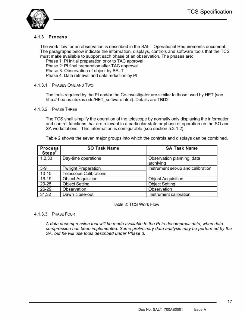
The work flow for an observation is described in the SALT Operational Requirements document.The paragraphs below indicate the information, displays, controls and software tools that the TCSmust make available to support each phase of an observation. The phases are:
Phase 1: PI initial preparation prior to TAC approvalPhase 2: PI final preparation after TAC approvalPhase 3: Observation of object by SALTPhase 4: Data retrieval and data reduction by PI
4.1.3.1 PHASES ONE AND TWO
The tools required by the PI and/or the Co-investigator are similar to those used by HET (seehttp://rhea.as.utexas.edu/HET_software.html). Details are TBD2.
4.1.3.2 PHASE THREE
The TCS shall simplify the operation of the telescope by normally only displaying the informationand control functions that are relevant in a particular state or phase of operation on the SO andSA workstations. This information is configurable (see section 5.3.1.2).
Table 2 shows the seven major groups into which the controls and displays can be combined.
ProcessSteps#
SO Task Name SA Task Name
1,2,33 Day-time operations Observation planning, dataarchiving
3-9 Twilight Preparation10-15 Telescope Calibrations
Instrument set-up and calibration
16-19 Object Acquisition Object Acquisition20-25 Object Setting Object Setting26-29 Observation Observation31,32 Dawn close-out Instrument calibration
Table 2: TCS Work Flow
4.1.3.3 PHASE FOUR
A data decompression tool will be made available to the PI to decompress data, when datacompression has been implemented. Some preliminary data analysis may be performed by theSA, but he will use tools described under Phase 3.

TCS Specification
Doc No. SALT1700AS0001 Issue A
18
5 System Technical Requirements
This section defines the performance characteristics of the TCS and allocates the functions identified insection 4 to specific items of equipment or software.
5.1 Schematic diagram
The physical layout of the Telescope can be found in the SALT System Specification and the fullSALT control system is shown in drawing 1000AD0005.
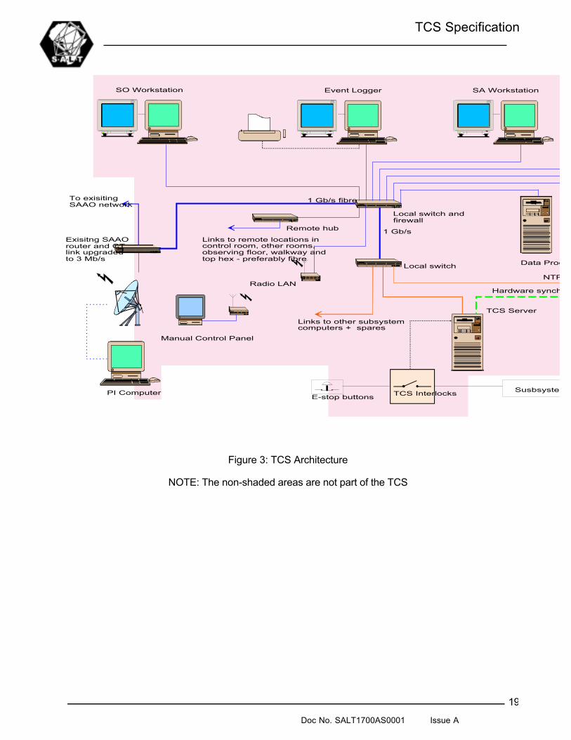
Figure 3 defines the proposed TCS Architecture and indicates the computer internal and externalcomputer interfaces. This information is provisional and will be superseded by detailed designs.
TCS Specification
Doc No. SALT1700AS0001 Issue A
19
SO Workstation Event Logger SA Workstation Data Reduction PC
Instr. 2 ComputerData Processor
TCS Server
NTP
Links to other time-critical processors +spare
Links to other subsystemcomputers + spares
Links to remote locations incontrol room, other rooms,observing floor, walkway andtop hex - preferably fibre
Remote hub
Local switch andfirewall
1 Gb/s fibre
1 Gb/s
To exisitingSAAO network
Exisitng SAAO router and CTlink upgradedto 3 Mb/s
Local switchInstr. 1 Computer
GPS timesource/server
Radio LAN
Manual Control Panel
TCS InterlocksE-stop buttons
PI Computer Susbsystem Interlocks
Hardware synch signal
Figure 3: TCS Architecture
NOTE: The non-shaded areas are not part of the TCS

TCS Specification
Doc No. SALT1700AS0001 Issue A
20
5.2 TCS Interfaces
5.2.1 External Interfaces
Figure 4 shows the major external interfaces of the TCS.
Facility
Structure
Tracker & Payload
CommissioningInstrument
ScienceInstruments
TCS
Primary Mirror
Dome
Cooling (C)Physical (P)Data (D)Optical (O)Air (A)Electrical (E)Ventilation (V)
Key to interfaces:
1 2
10
9
4
5
7
6
8
3
11
14
12
13
15
16
17
18
Existing Services
19
Figure 4: Schematic showing SALT Subsystem Interfaces
This information is provisional. The system interfaces shall comply with the Physical, Electrical andExternal Interface Control Dossiers referred to in Section 2, when these have been issued.
TCS Specification
Doc No. SALT1700AS0001 Issue A
21
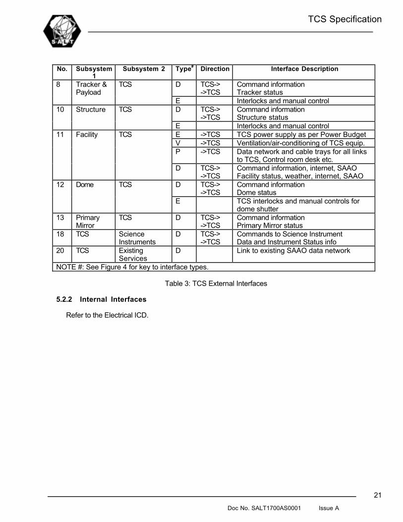
No. Subsystem1
Subsystem 2 Type# Direction Interface Description
D TCS->->TCS
Command informationTracker status
8 Tracker &Payload
TCS
E Interlocks and manual controlD TCS->
->TCSCommand informationStructure status
10 Structure TCS
E Interlocks and manual controlE ->TCS TCS power supply as per Power BudgetV ->TCS Ventilation/air-conditioning of TCS equip.P ->TCS Data network and cable trays for all links
to TCS, Control room desk etc.
11 Facility TCS
D TCS->->TCS
Command information, internet, SAAOFacility status, weather, internet, SAAO
D TCS->->TCS
Command informationDome status
12 Dome TCS
E TCS interlocks and manual controls fordome shutter
13 PrimaryMirror
TCS D TCS->->TCS
Command informationPrimary Mirror status
18 TCS ScienceInstruments
D TCS->->TCS
Commands to Science InstrumentData and Instrument Status info
20 TCS ExistingServices
D Link to existing SAAO data network
NOTE #: See Figure 4 for key to interface types.
Table 3: TCS External Interfaces
5.2.2 Internal Interfaces
Refer to the Electrical ICD.

TCS Specification
Doc No. SALT1700AS0001 Issue A
22
5.3 Characteristics
5.3.1 Performance
5.3.1.1 COMMUNICATION
a. The TCS shall provide a communications network for SALT using TCP/IP across an Ethernetnetwork. The Physical Layer and data will be defined in the Electrical ICD.
b. The data shall be communicated at a rate commensurate with the latency, bandwidth andtiming requirements of each data item.
c. It shall be possible to locate the SO Workstation and the SA Workstation anywhere on theSALT network or at the SAAO Cape Town.
d. It shall be possible to locate the Manual Control Panel anywhere on the SALT network.e. It shall be possible to connect many instances of the SO Workstation, SA Workstation and
Manual Control Panel, although certain control functions would then only be available at aselectable “master”.
f. A means shall be provided whereby changes to the data which is communicated betweencomputers, will not necessitate updates to all the computers’ software. A method using acentral “*.ini” file which is communicated to the various subsystem computers at start-up, issuggested. A tool to co-ordinate the “*.ini” file with the contents of the ICD is required (see5.4.5.1).
5.3.1.2 CONFIGURABLE MMI
The SO and SA workstations shall allow the user to configure the following characteristics ofthe display. It shall be possible to save such a configuration and return to it later so that eachuser has a custom “set-up”.• Open windows• Active window• Position of each window on each particular monitor• Default set of user-configured commands (see next section)
5.3.1.3 USER-CONFIGURED COMMANDS
It shall be possible for the user to schedule a series of defined steps/instructions/ commandsto be triggered at a particular time or with a simple key-stroke or mouse-click the user to“batch-process” activities that can be planned in advance (mouse-activated script files maysuffice). Examples of such actions are listed below:• Steps of a calibration process• Steps associated with a particular instrument change• All steps required to prepare SALT for the night (e.g. open shutter, turn off air-conditioning,
open louvers)• All admin steps required to proceed to the next observation (e.g. log all details in the
observation report, open new observation report and populate some fields)
5.3.1.4 OPERATOR TASK TIMES
a. The TCS SO and SA interface shall be such that once an object has been positioned in theacquisition field-of-view, a trained operator and astronomer will together take no longerthan 5 minutes (90th percentile) to perform all the following tasks:• Confirm that the correct object is displayed• Adjust the telescope rotation and pointing direction to correctly position the image in
the field• Switch the Tracker Payload fold mirror so that the light enters the science instrument
TCS Specification
Doc No. SALT1700AS0001 Issue A
23
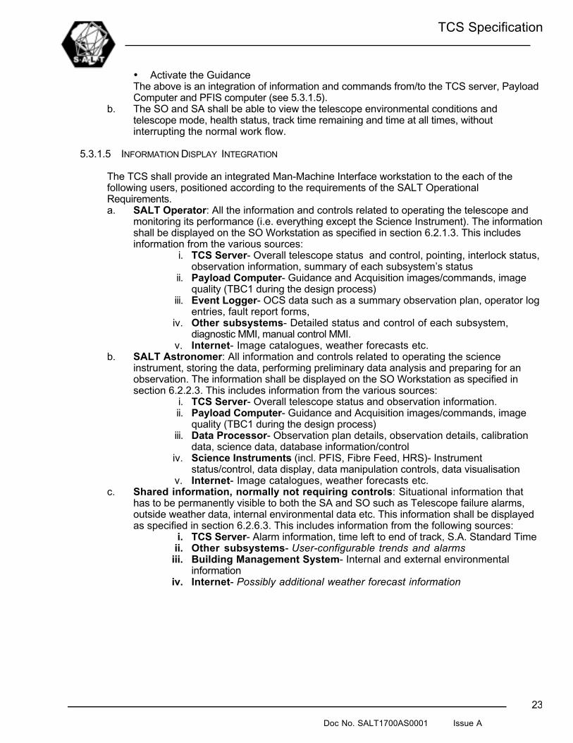
• Activate the GuidanceThe above is an integration of information and commands from/to the TCS server, PayloadComputer and PFIS computer (see 5.3.1.5).
b. The SO and SA shall be able to view the telescope environmental conditions andtelescope mode, health status, track time remaining and time at all times, withoutinterrupting the normal work flow.
5.3.1.5 INFORMATION DISPLAY INTEGRATION
The TCS shall provide an integrated Man-Machine Interface workstation to the each of thefollowing users, positioned according to the requirements of the SALT OperationalRequirements.a. SALT Operator: All the information and controls related to operating the telescope and
monitoring its performance (i.e. everything except the Science Instrument). The informationshall be displayed on the SO Workstation as specified in section 6.2.1.3. This includesinformation from the various sources:
i. TCS Server- Overall telescope status and control, pointing, interlock status,observation information, summary of each subsystem’s status
ii. Payload Computer- Guidance and Acquisition images/commands, imagequality (TBC1 during the design process)
iii. Event Logger- OCS data such as a summary observation plan, operator logentries, fault report forms,
iv. Other subsystems- Detailed status and control of each subsystem,diagnostic MMI, manual control MMI.
v. Internet- Image catalogues, weather forecasts etc.b. SALT Astronomer: All information and controls related to operating the science
instrument, storing the data, performing preliminary data analysis and preparing for anobservation. The information shall be displayed on the SO Workstation as specified insection 6.2.2.3. This includes information from the various sources:
i. TCS Server- Overall telescope status and observation information. ii. Payload Computer- Guidance and Acquisition images/commands, image
quality (TBC1 during the design process) iii. Data Processor- Observation plan details, observation details, calibration
data, science data, database information/control iv. Science Instruments (incl. PFIS, Fibre Feed, HRS)- Instrument
status/control, data display, data manipulation controls, data visualisation v. Internet- Image catalogues, weather forecasts etc.
c. Shared information, normally not requiring controls: Situational information thathas to be permanently visible to both the SA and SO such as Telescope failure alarms,outside weather data, internal environmental data etc. This information shall be displayedas specified in section 6.2.6.3. This includes information from the following sources:
i. TCS Server- Alarm information, time left to end of track, S.A. Standard Time ii. Other subsystems- User-configurable trends and alarms iii. Building Management System- Internal and external environmental
information iv. Internet- Possibly additional weather forecast information

TCS Specification
Doc No. SALT1700AS0001 Issue A
24
5.3.2 Physical Characteristics
5.3.2.1 LOCATION
The TCS components shall be located primarily in the SALT control room and computer rooms.
5.3.2.2 TELESCOPE AXIS SYSTEM
All subsystems shall comply with the axes defined in the SALT Axes and Calibration definitiondocument referred to in section 2.
5.3.2.2.1 Reference Axis System
The Reference Axis shall be used by the Pointing Model in the TCS to convert Celestial co-ordinates to the required local co-ordinates and vice-versa.
Although this axes system has its origin at the centre of the ideal upper surface of the pier,the software implementation of the pointing model may use an alternative reference (e.g. theoptical axis of the central Primary Mirror segment) if this is more practical.
5.3.2.2.2 Local Axes
a. All angular and position information transferred between the TCS and each of thesubsystems shall be in the local axes of each subsystem. The axes are relative to thephysical interfaces between the subsystem and its neighbours.
b. The pointing model in the TCS shall correct any fixed rotational or positional misalignmentof the reference planes from the design ideal.
c. The correction or calibration of any misalignment within each subsystem shall beperformed within that subsystem.
5.3.2.2.3 Celestial Axis System
All operator interfaces referring to sky object positions, shall use the Equatorial Axis Systemwhere the position of an object is defined in RA, DEC and sidereal time.
5.3.2.2.4 Pointing Model
a. A pointing model shall be provided in the TCS to compensate for system misalignments(see 6.2.4.3).
b. The pointing model shall be comprised of two parts:1. An analytical part, based on the known geometry of the Telescope and the measured
“static” misalignments measured between the interfaces of the subsystems2. An empirical part, comprising of a model built from the absolute residual errors
measured during Telescope commissioning and operation.

TCS Specification
Doc No. SALT1700AS0001 Issue A
25
5.3.3 Environmental Requirements
5.3.3.1 NORMAL OPERATIONAL ENVIRONMENT
The TCS shall meet all the requirements specified in this document when operated in thecomputer room and control room ambient condition defined in Table 4 below:
Parameter Value NotesMinimum Temperature in SALT roomsbelow observing floor
10ºC
Maximum Temperature in SALT roomsbelow observing floor
30ºC Excluding Mirror coating room, whereno active TCS equipment is located.
Minimum Temperature in TelescopeChamber
0ºC
Maximum Temperature in TelescopeChamber
20ºC
Minimum Humidity 5%Maximum Humidity 97% Non-condensingSite altitude 1798m
Table 4: TCS Normal Operating Environment
5.3.3.2 SURVIVAL ENVIRONMENT
The TCS shall survive when exposed to environment specified in Table 5 below (non-specifiedvalues as per 5.3.3.1).
Parameter Value NotesMinimum Temperature 0ºCMaximum Temperature 40ºCMaximum Humidity 100% Occasional exposure to condensing
conditions
Table 5: SALT Survival Operating Environment

TCS Specification
Doc No. SALT1700AS0001 Issue A
26
5.4 Operation and Maintenance Requirements
5.4.1 Packaging, handling, storage
Packaging, handling and storage requirements will be determined for each individual type ofcomponent, taking into account the specific requirements of the component, the method of shippingand interim storage locations. Storage at SALT will be in the SALT Store Room, in dry, air-conditioned conditions. Containers shall be sufficient for one return shipping only, unlessotherwise specified.
5.4.2 Product Documentation
A “SALT Pointing Calibration Instruction” document shall be defined, summarising the pointing modelcalibration and adjustment procedure.
For COTS equipment and software, the standard manufacturers documentation will be supplied,and no special documentation will be developed. Software documentation requirements aredefined in the SALT SW Standard.
5.4.3 Personnel and Training
5.4.3.1 OPERATION
SALT will be operated from the control room at the telescope. A SALT operator (SO) and aSALT Astronomer (SA) will be on duty during the whole night, for every operational night. Anyad hoc repair work will be performed by the SAAO standby maintenance staff, to be called bythe SO when required. The SO will have a National Diploma (N6/S3) or equivalent qualification inelectronic or mechanical engineering or have adequate experience. The SA will be a PhDastronomer.
5.4.3.2 MAINTENANCE
SALT will be maintained by the SAAO staff at Sutherland and Cape Town. Personnel will betrained in the maintenance of SALT, and be granted a “SALT – license” upon completion oftraining. All maintenance work carried out on SALT will be supervised/signed off by a SALTlicensed person. It is anticipated that the following people will be required to maintain SALT (thiswill be updated when the Operational Requirements have been received) :
At Sutherland:Mechanical Technician: 2Electronic Technician: 1Electrical Technician: 1In Cape Town:Mechanical Engineer: 1Electronic Engineer: 1Software Engineer: 1
These positions should not be SALT only, i.e. these personnel must be part of the SAAOtechnical staff, who will also work on the other SAAO telescopes. Thus, two Electronictechnicians, each working 50% on SALT, can constitute the one full time Electronic Technicianlisted above.

TCS Specification
Doc No. SALT1700AS0001 Issue A
27
One mechanical and one of the electrical/electronic technician will also required to be onstandby during every night of operations. These standby personnel will form part of the normalSAAO standby team.
In the above requirements, “Technicians” require a N6, T3 or equivalent qualification, and“Engineer” means an S6 or Bachelors degree in Engineering and/or Computer Science.
5.4.4 Availability
The TCS reliability is critical to the operation of SALT. The TCS Server shall not failcatastrophically (i.e. hang or experience hardware failure) more than once per year.
One of the other TCS machines shall be defined as a “backup TCS Server” and shall be able totake over the role of the TCS server within 10 minutes.
All normal maintenance actions will be able to be completed within one working day, unlessotherwise specified. Where maintenance actions take more than a day and happen regularly,enough spares will be held to ensure that the operation of the telescope system is not affected.
5.4.5 Test Equipment and Tools
5.4.5.1 INTERFACE MANAGEMENT TOOL
A means shall be provided to automate the update of Ethernet-communicated data directly fromthe ICD. A simple tool that creates the “*.ini” file specified in section 5.3.1.1, directly from anExcel spreadsheet containing the ICD, is suggested.
5.4.5.2 DATA MONITORING TOOL
A tool shall be provided that displays the value of any selected parameter or set of parametersbeing communicated between computers. The tools shall be able to record the data for a period.
5.4.5.3 TCS SIMULATOR
A TCS simulator shall be provided to perform subsystem testing prior to final system integration(see 6.2.4.3.8).
5.4.6 Data and Software Backups
A system to automatically create backups of critical data and software shall be installed.Backups are to be copied and stored in a separate building on at least a weekly basis.
TCS Specification
Doc No. SALT1700AS0001 Issue A
28
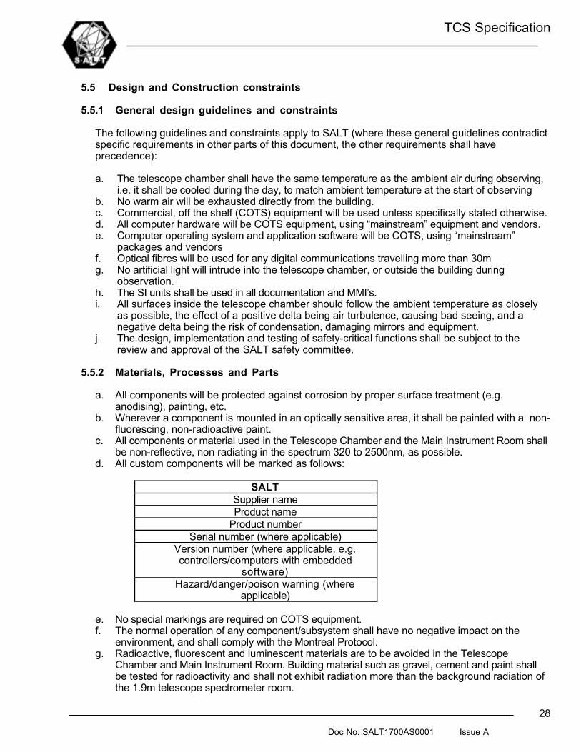
5.5 Design and Construction constraints
5.5.1 General design guidelines and constraints
The following guidelines and constraints apply to SALT (where these general guidelines contradictspecific requirements in other parts of this document, the other requirements shall haveprecedence):
a. The telescope chamber shall have the same temperature as the ambient air during observing,i.e. it shall be cooled during the day, to match ambient temperature at the start of observing
b. No warm air will be exhausted directly from the building.c. Commercial, off the shelf (COTS) equipment will be used unless specifically stated otherwise.d. All computer hardware will be COTS equipment, using “mainstream” equipment and vendors.e. Computer operating system and application software will be COTS, using “mainstream”
packages and vendorsf. Optical fibres will be used for any digital communications travelling more than 30mg. No artificial light will intrude into the telescope chamber, or outside the building during
observation.h. The SI units shall be used in all documentation and MMI’s.i. All surfaces inside the telescope chamber should follow the ambient temperature as closely
as possible, the effect of a positive delta being air turbulence, causing bad seeing, and anegative delta being the risk of condensation, damaging mirrors and equipment.
j. The design, implementation and testing of safety-critical functions shall be subject to thereview and approval of the SALT safety committee.
5.5.2 Materials, Processes and Parts
a. All components will be protected against corrosion by proper surface treatment (e.g.anodising), painting, etc.
b. Wherever a component is mounted in an optically sensitive area, it shall be painted with a non-fluorescing, non-radioactive paint.
c. All components or material used in the Telescope Chamber and the Main Instrument Room shallbe non-reflective, non radiating in the spectrum 320 to 2500nm, as possible.
d. All custom components will be marked as follows:
SALTSupplier nameProduct name
Product numberSerial number (where applicable)
Version number (where applicable, e.g.controllers/computers with embedded
software)Hazard/danger/poison warning (where
applicable)
e. No special markings are required on COTS equipment.f. The normal operation of any component/subsystem shall have no negative impact on the
environment, and shall comply with the Montreal Protocol. g. Radioactive, fluorescent and luminescent materials are to be avoided in the Telescope
Chamber and Main Instrument Room. Building material such as gravel, cement and paint shallbe tested for radioactivity and shall not exhibit radiation more than the background radiation ofthe 1.9m telescope spectrometer room.

TCS Specification
Doc No. SALT1700AS0001 Issue A
29
5.5.3 Electromagnetic Radiation
The normal operation of any component or system will not affect the normal operation of any othersystem or component, or any other equipment at the Observatory at Sutherland, and has to complywith the EMC standards as defined in the SALT Electrical Requirements document.
5.5.4 Workmanship
Workmanship shall comply with good practice in the computer industry (e.g. ISO9001and ISO9002).
5.5.5 Interchangeability
Interchangeability shall be maximised by using identical COTS equipment wherever possible.
5.5.6 Safety
5.5.6.1 SAFETY-CRITICAL FAILURES
All single-point failures that can lead to loss of life, serious injury to personnel or damage toequipment shall be identified and the design modified to prevent such failures.
A preliminary safety analysis to identify such potential failures is contained in the SALT SafetyAnalysis referred to in section 2.
5.5.6.2 SOFTWARE SAFETY
Where the malfunction of software alone could cause a safety-critical failure, alternate meansshall be provided to prevent the occurrence of such a failure. This would typically take the formof electrical interlocks designed in a fail-safe manner (see 6.2.7.3).
5.5.6.3 SAFE INITIALISATION
All systems, when initialising from power-up or when reset, shall be in a safe, non-active state(e.g. equipment stationary, drives off). It shall take a specific command from the TCS (byexception) or the operator via the TCS, to proceed with potentially unsafe actions (such asrotating the structure or dome, moving the tracker or opening/closing the shutter).
5.5.6.4 EMERGENCY STOP
Emergency stop buttons will be located at various locations in the building (as defined in theSALT System Specification). The TCS shall provide a central hub to which these signals arerouted and shall initiate appropriate action. The action shall be trigger by software commands tothe appropriate subsystems and also by hardware signals (see 6.2.7.3), where applicable. Thefinal design will be subject to the Safety Analysis Document listed in Section 2.
5.5.6.5 ENHANCEMENT OF OPERATOR AWARENESS
Potentially unsafe commands that can be initiated by the operator using the TCS MMI, shallaccompanied by suitable warnings and confirmations to enhance the operators awareness ofthe unsafe condition.
5.5.7 Ergonomics
Comfortable working positions and conditions shall be provided at both workstations.
TCS Specification
Doc No. SALT1700AS0001 Issue A
30
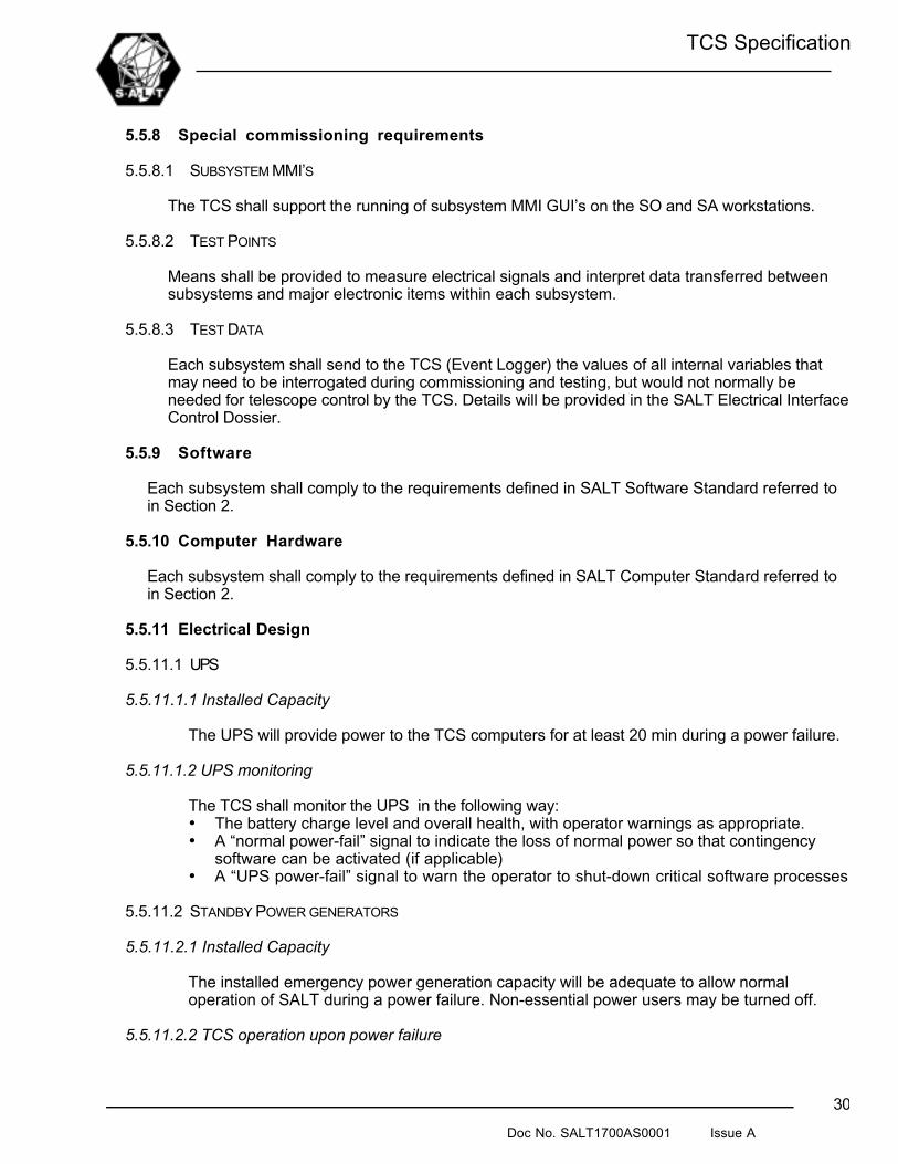
5.5.8 Special commissioning requirements
5.5.8.1 SUBSYSTEM MMI’S
The TCS shall support the running of subsystem MMI GUI’s on the SO and SA workstations.
5.5.8.2 TEST POINTS
Means shall be provided to measure electrical signals and interpret data transferred betweensubsystems and major electronic items within each subsystem.
5.5.8.3 TEST DATA
Each subsystem shall send to the TCS (Event Logger) the values of all internal variables thatmay need to be interrogated during commissioning and testing, but would not normally beneeded for telescope control by the TCS. Details will be provided in the SALT Electrical InterfaceControl Dossier.
5.5.9 Software
Each subsystem shall comply to the requirements defined in SALT Software Standard referred toin Section 2.
5.5.10 Computer Hardware
Each subsystem shall comply to the requirements defined in SALT Computer Standard referred toin Section 2.
5.5.11 Electrical Design
5.5.11.1 UPS
5.5.11.1.1 Installed Capacity
The UPS will provide power to the TCS computers for at least 20 min during a power failure.
5.5.11.1.2 UPS monitoring
The TCS shall monitor the UPS in the following way:• The battery charge level and overall health, with operator warnings as appropriate.• A “normal power-fail” signal to indicate the loss of normal power so that contingency
software can be activated (if applicable)• A “UPS power-fail” signal to warn the operator to shut-down critical software processes
5.5.11.2 STANDBY POWER GENERATORS
5.5.11.2.1 Installed Capacity
The installed emergency power generation capacity will be adequate to allow normaloperation of SALT during a power failure. Non-essential power users may be turned off.
5.5.11.2.2 TCS operation upon power failure

TCS Specification
Doc No. SALT1700AS0001 Issue A
31
The emergency power source shall has the following features:• It will become active within 30s of a general power failure and will remain on until
manually turned off• The quality of power (voltage, frequency drift, harmonics) will be no worse than the
normal electrical supply• At least the following error conditions will also be reported to the TCS: low fuel, low oil
pressure, generator fault, low voltage, over-current, system overheating, power status(normal, emergency, off).
If the generator fails to start after a power failure an operator warning shall be generated sothat critical software processes can be shut down.
5.5.12 Data security
a. The TCS shall allow various users to log in with different levels of security. The following levelof access are required, each with their own particular restrictions:• SA• SO• Maintainer• Administrator• PI• Co-Investigator• Partner• Guest
b. A firewall shall protect the SALT network from unauthorised access outside the site.
5.5.13 Future growth
The following potential growth areas shall be borne in mind during the design process andaccommodated where this does not have an impact on the achievement of the immediateperformance, schedule and cost requirements.
5.5.13.1 PHASING
The primary mirror array of SALT may be required to be phased in future, to make use of theadvantages of Adaptive Optics (AO).
5.5.13.2 IMPROVED OPTICAL PERFORMANCE
The optical performance of SALT may be improved by using the latest technology mirrorcoatings.
5.5.13.3 IR PFIS
A near IR channel may be added to the PFIS.
5.5.13.4 REMOTE OBSERVING
The whole or parts of the SALT control room may be required to be duplicated at the SAAO inCape Town, to allow remote operating of SALT.
5.5.13.5 ADDITIONAL INSTRUMENTS
Specific provisions shall be made in the TCS architecture, network sizing and MMI design tofacilitate the addition of more science instruments during SALT’s life-time.

TCS Specification
Doc No. SALT1700AS0001 Issue A
32
5.5.13.6 DATA MIRROR OFF-SITE
The science data and PI-related software may later be moved to a mirror site elsewhere, tominimise data communication between Sutherland and Cape Town.
TCS Specification
Doc No. SALT1700AS0001 Issue A
33
6 Subsystem Technical Requirements
6.1 Major Component List
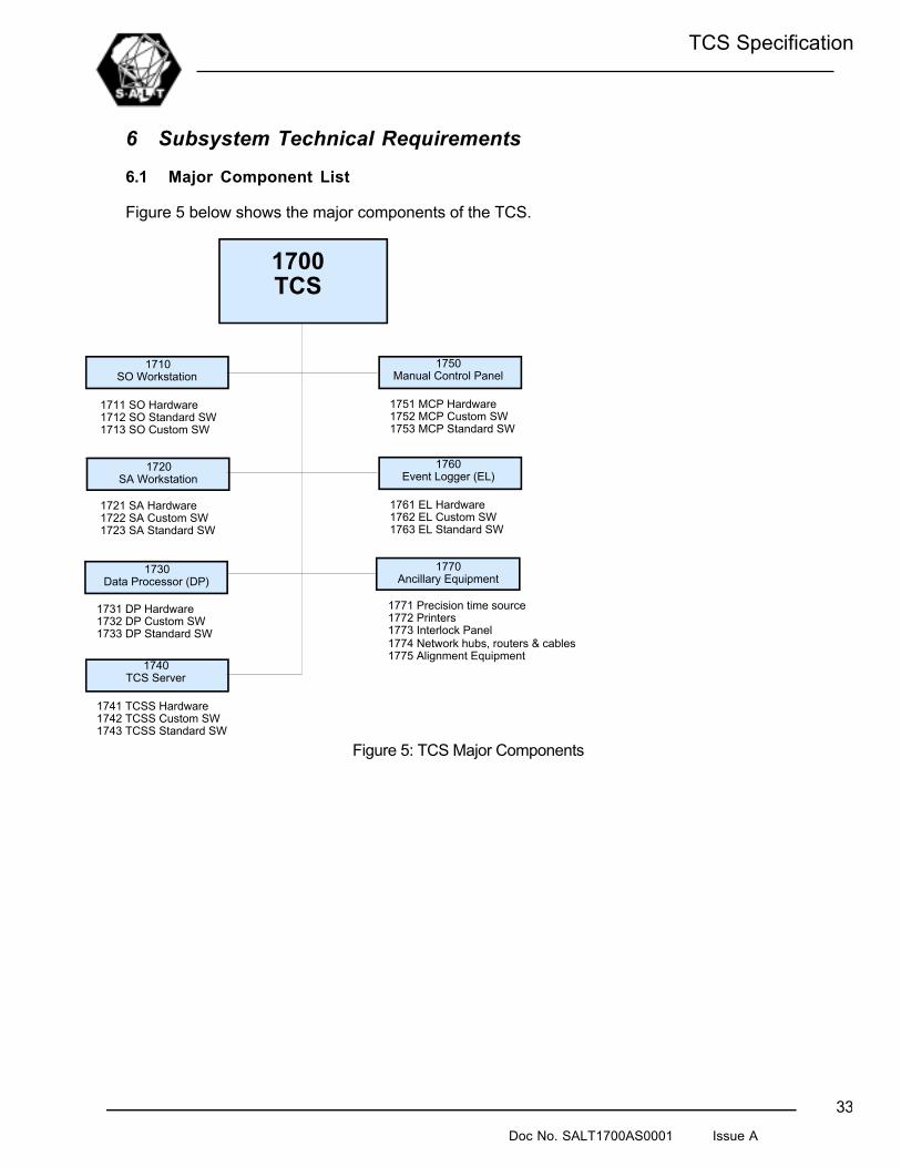
Figure 5 below shows the major components of the TCS.
1700TCS
1710SO Workstation
1720SA Workstation
1730Data Processor (DP)
1770Ancillary Equipment
1711 SO Hardware1712 SO Standard SW1713 SO Custom SW
1771 Precision time source1772 Printers1773 Interlock Panel1774 Network hubs, routers & cables1775 Alignment Equipment
1750Manual Control Panel
1721 SA Hardware1722 SA Custom SW 1723 SA Standard SW
1731 DP Hardware1732 DP Custom SW 1733 DP Standard SW
1740TCS Server
1741 TCSS Hardware1742 TCSS Custom SW 1743 TCSS Standard SW
1751 MCP Hardware1752 MCP Custom SW 1753 MCP Standard SW
1760Event Logger (EL)
1761 EL Hardware1762 EL Custom SW 1763 EL Standard SW
Figure 5: TCS Major Components
TCS Specification
Doc No. SALT1700AS0001 Issue A
34
6.2 Subsystem Characteristics
6.2.1 SO Workstation
6.2.1.1 HARDWARE
The SO workstation shall comprise a Pentium PC with the appropriate network card (see6.2.7.4). Detailed requirements can be found in the SALT Computer Standard.
This PC shall have two large monitors (17” or larger) and shall be located in the SALT controlroom. The user interface shall be a single keyboard and mouse.
6.2.1.2 STANDARD SOFTWARE
The following standard software shall be installed on this machine:• Linux operating system in accordance with the SALT SW Standard• X-Windows environment• GNU-C• KDE• Star Office
6.2.1.3 CUSTOM SOFTWARE
6.2.1.3.1 Purpose
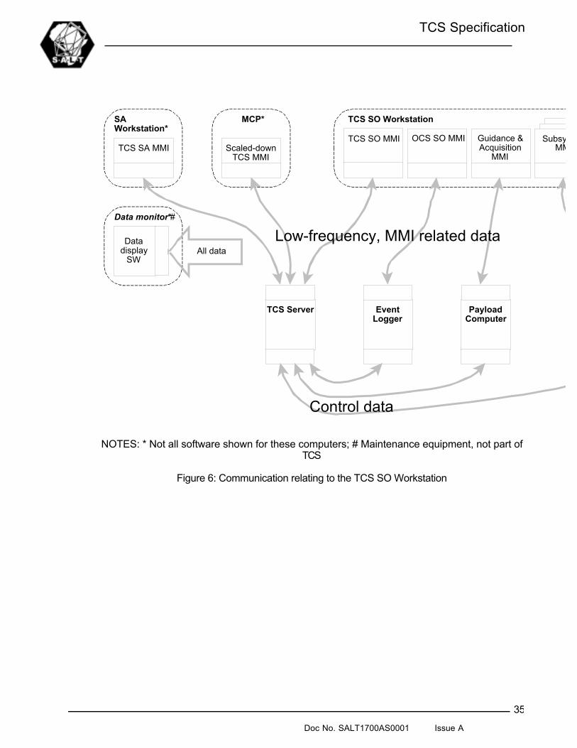
The purpose of the SO Workstation is to provide the full interface to the SO to control thetelescope. It displays information from various computers and can send commands to thesecomputers, as shown in Figure 6 overleaf.
TCS Specification
Doc No. SALT1700AS0001 Issue A
35
Session 1
Session 2
Session 2
X-Windows PC*#TCS SO Workstation
TCS SO MMI OCS SO MMI Guidance &Acquisition
MMI
SubsystemMMI
MCP*SAWorkstation*
Data monitor*#
TCS Server PayloadComputer
EventLogger
SubsystemComputers
Scaled-downTCS MMI
TCS SA MMI
Datadisplay
SW
Low-frequency, MMI related data
Control data
All data
NOTES: * Not all software shown for these computers; # Maintenance equipment, not part ofTCS
Figure 6: Communication relating to the TCS SO Workstation
TCS Specification
Doc No. SALT1700AS0001 Issue A
36
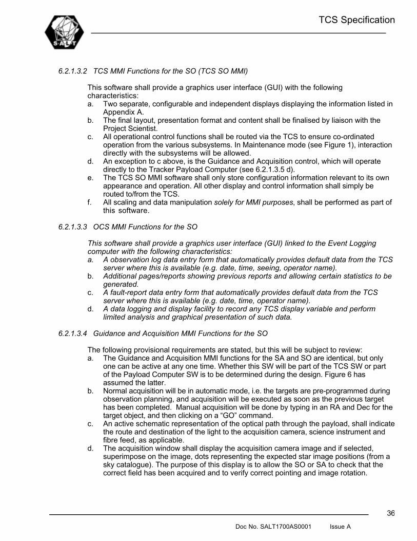
6.2.1.3.2 TCS MMI Functions for the SO (TCS SO MMI)
This software shall provide a graphics user interface (GUI) with the followingcharacteristics:a. Two separate, configurable and independent displays displaying the information listed in
Appendix A.b. The final layout, presentation format and content shall be finalised by liaison with the
Project Scientist.c. All operational control functions shall be routed via the TCS to ensure co-ordinated
operation from the various subsystems. In Maintenance mode (see Figure 1), interactiondirectly with the subsystems will be allowed.
d. An exception to c above, is the Guidance and Acquisition control, which will operatedirectly to the Tracker Payload Computer (see 6.2.1.3.5 d).
e. The TCS SO MMI software shall only store configuration information relevant to its ownappearance and operation. All other display and control information shall simply berouted to/from the TCS.
f. All scaling and data manipulation solely for MMI purposes, shall be performed as part ofthis software.
6.2.1.3.3 OCS MMI Functions for the SO
This software shall provide a graphics user interface (GUI) linked to the Event Loggingcomputer with the following characteristics:a. A observation log data entry form that automatically provides default data from the TCS
server where this is available (e.g. date, time, seeing, operator name).b. Additional pages/reports showing previous reports and allowing certain statistics to be
generated.c. A fault-report data entry form that automatically provides default data from the TCS
server where this is available (e.g. date, time, operator name).d. A data logging and display facility to record any TCS display variable and perform
limited analysis and graphical presentation of such data.
6.2.1.3.4 Guidance and Acquisition MMI Functions for the SO
The following provisional requirements are stated, but this will be subject to review:a. The Guidance and Acquisition MMI functions for the SA and SO are identical, but only
one can be active at any one time. Whether this SW will be part of the TCS SW or partof the Payload Computer SW is to be determined during the design. Figure 6 hasassumed the latter.
b. Normal acquisition will be in automatic mode, i.e. the targets are pre-programmed duringobservation planning, and acquisition will be executed as soon as the previous targethas been completed. Manual acquisition will be done by typing in an RA and Dec for thetarget object, and then clicking on a “GO” command.
c. An active schematic representation of the optical path through the payload, shall indicatethe route and destination of the light to the acquisition camera, science instrument andfibre feed, as applicable.
d. The acquisition window shall display the acquisition camera image and if selected,superimpose on the image, dots representing the expected star image positions (from asky catalogue). The purpose of this display is to allow the SO or SA to check that thecorrect field has been acquired and to verify correct pointing and image rotation.

TCS Specification
Doc No. SALT1700AS0001 Issue A
37
e. The acquisition window shall also, when selected, superimpose on the acquisitionimage, fiducial marks representing the instrument or fibre feed slit positions andorientations. A means shall be provided whereby the SO or SA can interactively re-orientate and move the telescope to the required orientation using a mouse. The dataused to position the fiducial marks shall be received from the relevant instrument or fibrefeed system.
f. The guidance window shall display the image from the guidance camera. Guidance willbe activated by mouse selection of the guidance object and appropriate symbology willbe superimposed on the image to indicate that guidance is in process. A means shall beprovided whereby the SO or SA can interactively re-orientate and move the telescope(add guidance offsets) either by typing in offset or using a mouse. It shall also bepossible to accept guidance offsets from a science instrument.
6.2.1.3.5 Other subsystem MMI Functions for the SO
The details of this requirement are to be determined in co-operation with the subsystemdesigners. The following is envisaged at this stage:a. A GUI that either runs on the subsystem computer but displays on the SO Workstation
(using X-Windows) or, preferably, a separate MMI executable that runs on the SOworkstation but has a data link to the appropriate subsystem computer.
b. During normal operation the GUI provides information only and all control functions aredisabled (the master control being performed via the TCS MMI software).
c. When the entire system is placed in “Maintenance Mode” (see Figure 1), the subsystemcontrol functions are enabled and commands from the TCS are overridden. Appropriatewarning messages appear on the TCS SO MMI.
d. The exception to the above is the Guidance and Acquisition function of the TrackerPayload Computer, which will be used during normal operation and will not be duplicatedin the TCS SO MMI.
6.2.2 SA Workstation
6.2.2.1 HARDWARE
The SA workstation shall comprise a Pentium PC with the appropriate network card (see6.2.7.4). Detailed requirements can be found in the SALT Computer Standard.
This PC shall have two large monitors (17” or larger) and shall be located in the SALT controlroom. The user interface shall be a single keyboard and mouse.
6.2.2.2 STANDARD SOFTWARE
The following standard software shall be installed on this machine:• Linux operating system in accordance with the SALT SW Standard• X-Windows environment• GNU-C• KDE• Star Office• IRAF

TCS Specification
Doc No. SALT1700AS0001 Issue A
38
6.2.2.3 CUSTOM SOFTWARE
6.2.2.3.1 Purpose
The purpose of the SA Workstation is to provide the full interface to the SA to schedule anobservation and perform it by monitoring the telescope and controlling the instrument. Itdisplays information from various computers and can send commands to these computers,as shown in Figure 7.
6.2.2.3.2 TCS MMI Functions for the SA (TCS SA MMI)
This software is a scaled-down version of the SO MMI and shall provide a graphics userinterface (GUI) with the following characteristics:a. One configurable (limited) and display displaying the information listed in Appendix B.b. The final layout, presentation format and content shall be finalised by liaison with the
Project Scientist.c. All telescope operational control functions shall be routed via the TCS to ensure co-
ordinated operation from the various subsystems. In Maintenance mode (see Figure 1),interaction directly with the subsystems will be allowed. Direct interaction with theInstrument will generally be allowed.
d. An exception to c above, is the Guidance and Acquisition control, which will operatedirectly to the Tracker Payload Computer (see 6.2.1.3.5 d).
e. The TCS SA MMI software shall only store configuration information relevant to its ownappearance and operation. All other display and control information shall simply berouted to/from the TCS.
f. All scaling and data manipulation solely for MMI purposes, shall be performed as part ofthis software.

TCS Specification
Doc No. SALT1700AS0001 Issue A
39
Session 1
Session 2
Session 2
X-Windows PC*#TCS SA Workstation
TCS SA MMI OCS SA MMI Guidance &Acquisition
MMI
InstrumentMMI
MCP*SOWorkstation*
Data monitor*#
TCS Server PayloadComputer
DataProcessor
InstrumentComputers
Scaled-downTCS MMI
TCS SO MMI
Datadisplay
SW
Low-frequency, MMI related data
Control data
All data
NOTES: * Not all software shown for these computers; # Maintenance equipment, not part ofTCS
Figure 7: Communication relating to the TCS SA Workstation
TCS Specification
Doc No. SALT1700AS0001 Issue A
40
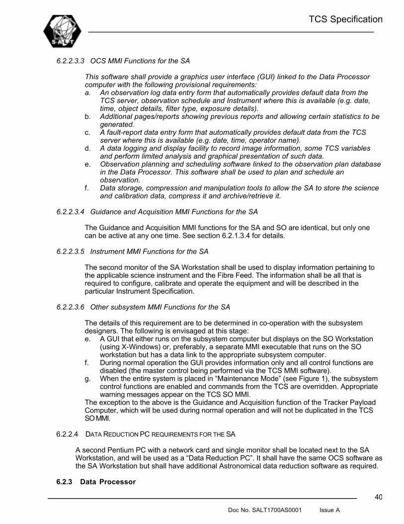
6.2.2.3.3 OCS MMI Functions for the SA
This software shall provide a graphics user interface (GUI) linked to the Data Processorcomputer with the following provisional requirements:a. An observation log data entry form that automatically provides default data from the
TCS server, observation schedule and Instrument where this is available (e.g. date,time, object details, filter type, exposure details).
b. Additional pages/reports showing previous reports and allowing certain statistics to begenerated.
c. A fault-report data entry form that automatically provides default data from the TCSserver where this is available (e.g. date, time, operator name).
d. A data logging and display facility to record image information, some TCS variablesand perform limited analysis and graphical presentation of such data.
e. Observation planning and scheduling software linked to the observation plan databasein the Data Processor. This software shall be used to plan and schedule anobservation.
f. Data storage, compression and manipulation tools to allow the SA to store the scienceand calibration data, compress it and archive/retrieve it.
6.2.2.3.4 Guidance and Acquisition MMI Functions for the SA
The Guidance and Acquisition MMI functions for the SA and SO are identical, but only onecan be active at any one time. See section 6.2.1.3.4 for details.
6.2.2.3.5 Instrument MMI Functions for the SA
The second monitor of the SA Workstation shall be used to display information pertaining tothe applicable science instrument and the Fibre Feed. The information shall be all that isrequired to configure, calibrate and operate the equipment and will be described in theparticular Instrument Specification.
6.2.2.3.6 Other subsystem MMI Functions for the SA
The details of this requirement are to be determined in co-operation with the subsystemdesigners. The following is envisaged at this stage:e. A GUI that either runs on the subsystem computer but displays on the SO Workstation
(using X-Windows) or, preferably, a separate MMI executable that runs on the SOworkstation but has a data link to the appropriate subsystem computer.
f. During normal operation the GUI provides information only and all control functions aredisabled (the master control being performed via the TCS MMI software).
g. When the entire system is placed in “Maintenance Mode” (see Figure 1), the subsystemcontrol functions are enabled and commands from the TCS are overridden. Appropriatewarning messages appear on the TCS SO MMI.
The exception to the above is the Guidance and Acquisition function of the Tracker PayloadComputer, which will be used during normal operation and will not be duplicated in the TCSSO MMI.
6.2.2.4 DATA REDUCTION PC REQUIREMENTS FOR THE SA
A second Pentium PC with a network card and single monitor shall be located next to the SAWorkstation, and will be used as a “Data Reduction PC”. It shall have the same OCS software asthe SA Workstation but shall have additional Astronomical data reduction software as required.
6.2.3 Data Processor

TCS Specification
Doc No. SALT1700AS0001 Issue A
41
6.2.3.1 HARDWARE
The Data Processor shall comprise a Pentium PC with the appropriate network card (see6.2.7.4). Detailed requirements can be found in the SALT Computer Standard.
A CD-writer and/or Tape Drive shall be installed to archive data. A hard-disk of sufficientcapacity to store 2 weeks of data shall be installed (size ~40GB).
6.2.3.2 STANDARD SOFTWARE
The following standard software shall be installed on this machine:• Linux operating system in accordance with the SALT SW Standard• X-Windows environment• GNU-C• KDE• Star Office• Database SW (specific type is to be determined during the design)
6.2.3.3 CUSTOM SOFTWARE
The following custom software shall be installed on the Data Processor, primarily for use by thePI’s and the SA.
• Observation planning tools for the PI and the SA (details TBD2)• Observation scheduling tools for the SA (details TBD2)• Data compression tool• Science and calibration data storage, archiving and retreival software• Observation log form generator and database• Sky catalogue or star image database
6.2.4 TCS Server
6.2.4.1 HARDWARE
The TCS server shall comprise the fastest available Pentium PC, at least 128MB of memory,timing input card and with the appropriate network card (see 6.2.7.4). Other requirements canbe found in the SALT Computer Standard.
6.2.4.2 STANDARD SOFTWARE
The following standard software shall be installed on this machine:• Linux operating system in accordance with the SALT SW Standard• X-Windows environment• GNU-C• KDE
6.2.4.3 CUSTOM SOFTWARE
6.2.4.3.1 Purpose
The purpose of the TCS Server is to co-ordinate the operation of all the SALT subsystemsaccording to the commands of the SO and SA and to monitor each subsystem’sperformance. It is the “integrating node” of the entire telescope.

TCS Specification
Doc No. SALT1700AS0001 Issue A
42
6.2.4.3.2 Co-ordination of subsystem initialisation
The TCS shall co-ordinate the initialisation of each subsystem by:a. Monitoring the initialisation status of each subsystem computerb. Remaining in “initialisation mode” until all initialisation is completed or a preset period of
time has elapsedc. Reporting as a fault, any subsystem that fails to complete initialisation in the allocated
time.
6.2.4.3.3 Pointing Model Functions
The TCS shall perform the angular/time transformations required to position an object at thedesired position in the acquisition field. The system pointing accuracy is specified in the SALTSystem Specification and a portion of this is allocated to the TCS Pointing Model (see theSALT Error Budget).
The Pointing model shall do the following:a. Perform all astrometric calculations required to convert the object position to Telescope
Axes.b. Perform axis transformations to determine required tracker X, Y, Z, phi, theta and Rho
orientation, required Structure angle, required Dome angle to point at the object.c. Perform adjustments to the Pointing Model to optimise pointing with time by modelling
certain factors that influence pointing.d. Allow adjustment of the pointing parameters based on measurements of system and
subsystem misalignments.
6.2.4.3.4 System mode control
The TCS Server shall co-ordinate the modes and actions of each individual subsystem basedon the TCS mode (as defined in 4.1.2.2.1) and user-initiated commands. A state-machineshall ensure an unambiguous and consistent relationship between the TCS mode and thesubsystem modes.
6.2.4.3.5 System Safety monitoring
The TCS Server shall monitor subsystem failures and initiate steps to prevent hazardoussituations (e.g. to enter the “Major Failure” state and halting all movements). Unsafeconditions shall be reported via the Event Logger and/or the SO and SA workstations.
The TCS Server shall monitor signals form the emergency stop switches and safety interlockpanel (see 6.2.7.3) and generate appropriate software commands.
The TCS Server shall also monitor the communication with each of the subsystem computersusing a Single Point Communication Test (as defined in the SALT SW Standard document)and report failures to the operator.
6.2.4.3.6 Tracker Trajectory determination
The TCS server shall, based on the pointing model outputs, send to the Tracker an idealtracking trajectory (in all six degrees of freedom) to perform open-loop tracking of an objectat a sidereal or pre-programmed rate. The trajectory shall be updated at least once every15s, taking into account the latest guidance errors.
6.2.4.3.7 Precision command synchronisation

TCS Specification
Doc No. SALT1700AS0001 Issue A
43
Time-critical commands communicated by TCS to subsystems shall be “future-dated” by0.25s (TBD3) and time-stamped accordingly. The recipient shall place the commands in abuffer and only execute them at the required time instant, based on the information from theprecision time source (see 6.2.7.1).
Time-critical responses received by the TCS shall be handled in a converse fashion.
6.2.4.3.8 Subsystem simulation
A special version of the TCS Server software shall be created, with minimal deviation fromthe original, which instead of communicating to the subsystems, can selectively perform alimited simulation any/all of the subsystem computers.
The purpose of this “TCS Simulator” is to test each subsystem’s interface to the TCS andother subsystems, during subsystem testing. Details are TBD4.
6.2.5 Manual Control Panel
6.2.5.1 HARDWARE
The Manual Control Panel shall comprise a ruggedised Pentium Notebook with the appropriatenetwork card connected to a radio-modem (see 6.2.7.4).
6.2.5.2 STANDARD SOFTWARE
Windows NT or Linux, as defined in the SALT SW Standard.
6.2.5.3 CUSTOM SOFTWARE
6.2.5.3.1 Purpose
The MCP software is a simplified version of the TCS SO MMI software, which allowsmaintenance personnel to perform certain functions from the telescope floor.
6.2.5.3.2 Software Requirements
This software shall provide a GUI with controls and feedback that will allow at least thefollowing commands:a. Opening and closing of the Dome Shutterb. Dome fast and slow rotation in either directionc. Lifting and lowering of the structured. Structure fast and slow rotation in either directione. Tracker fast, slow and inching in the X and Y directionsf. Tracker payload fast and slow Tip, Tilt, Rho and Z movement
These commands will only be available if the MCP has been enabled from the SO and SAworkstations.
6.2.6 Event Logger
6.2.6.1 HARDWARE
The Event Logger shall comprise a Pentium PC with the appropriate network card (see 6.2.7.4).Detailed requirements can be found in the SALT Computer Standard.

TCS Specification
Doc No. SALT1700AS0001 Issue A
44
This PC shall have two large monitors (17” or larger) and shall be located in the SALT controlroom. The used interface shall be a single keyboard and mouse. A sound card shall be installed,that either interfaces to the control room audio system or has its own local speaker. Hard-diskcapacity shall be ~20GB.
6.2.6.2 STANDARD SOFTWARE
Windows NT or Linux, as defined in the SALT SW Standard.
6.2.6.3 CUSTOM SOFTWARE
6.2.6.3.1 Purpose
The Event Logger provides information to be displayed to both the SO and SA but alsocollects data from the telescope for logging and alarming purposes. It also contains thedatabase for telescope operational information (OCS).
6.2.6.3.2 Software Requirements
The following specific requirements shall be met:a. The information listed in Appendix C shall be displayed. It will be obtained locally, from
the TCS Server and from the BMS.b. The weather information shall be published in a format that can be read using a
standard web browser and shall be available on the SAAO network.c. The Event logger shall monitor critical telescope and environmental parameters and
generate audible and visible alarms when appropriate.d. Critical alarms shall also be displayed at the SO Workstation It shall be possible to
acknowledge alarms from the SO workstation.e. Telescope health shall be indicated at a high level and a “drill-down” capability
provided to see detailed failures when these occur.f. Telescope failures shall be logged in a file.g. A database program that interfaces to the SO workstation, shall record telescope-
related fault-reports and SO operator logs.h. It shall be possible to perform user-configurable recording of data communicated
between computers, for diagnostic purposes. Graphing/trending of the data shall bepossible.
6.2.7 Ancillary Equipment
6.2.7.1 PRECISION TIME SOURCE
A GPS time-source shall provide absolute time to the TCS and the other SALT subsystems. Itshall provide this in two ways:a. A network time signal using NTP, with an average accuracy of better than 150ms.b. A hardware time signal comprising 1kHz and 1Hz hardware pulses with an accuracy of
better than 0.1ms.
6.2.7.2 PRINTERS
A postscript-compatible laser printer shall be connected to one of the control room computers(possibly the event logger). Detailed requirements are to be defined during the design.
6.2.7.3 INTERLOCK PANEL
A hardware interlock panel shall be provided to generate safety-inhibit signals based on

TCS Specification
Doc No. SALT1700AS0001 Issue A
45
hardware and software inputs. These signals shall be routed to the applicable subsystems andwhen activated, shall halt all potentially unsafe actions. The list of unsafe conditions requiringsystem-level interlocks will be identified in the SALT Safety Analysis document. The method ofinterfacing to each subsystem shall preferable be a voltage-free, normally-closed contact, butdetails will be contained in the SALT Electrical ICD.
6.2.7.4 NETWORK HUBS, ROUTERS AND CABLES
The following provisional requirements are stated, but these will be subject to confirmationduring the final design:a. The Sutherland-to-Internet backbone data link shall be upgraded to at least 2.5 Mb/s to
support transfer of science data within reasonable times.b. The SALT network shall be linked to the SAAO network at Sutherland.c. The SALT control network and the SALT information network shall be separated by a
router, such that the transfer of science data from the appropriate instrument computer tothe Data Processor and from the Data Processor to the Internet or SAAO, does notdegrade the control network throughput. The control network contains the nodesconnected to subsystem computers and the TCS server whereas the data network isconnected to the Data Processor, SO and SA workstations and Internet. These networksare shown as red and blue respectively on the SALT computer architecture drawing.
d. The network shall be the fasted affordable, mature technology, and if possible, be opticfibre-based. As a minimum, this shall be 100BaseT Ethernet.
e. The data link connecting the SALT building to the SAAO shall be optical fibre, preferablywith a 1Gb/s throughput (to accommodate future growth).
f. A radio-modem shall be supplied to connect the MCP to the SALT network.g. A firewall shall be used to restrict communication to the SALT network, to authorised
computers only. The corollary of this is that the PI’s will need to access a machine outsidethe SALT network (i.e. a SALT Mirror site) as mentioned in section 5.5.13.6.
6.2.7.5 ALIGNMENT EQUIPMENT
The requirement for alignment equipment will be determined during the Pointing Model design.
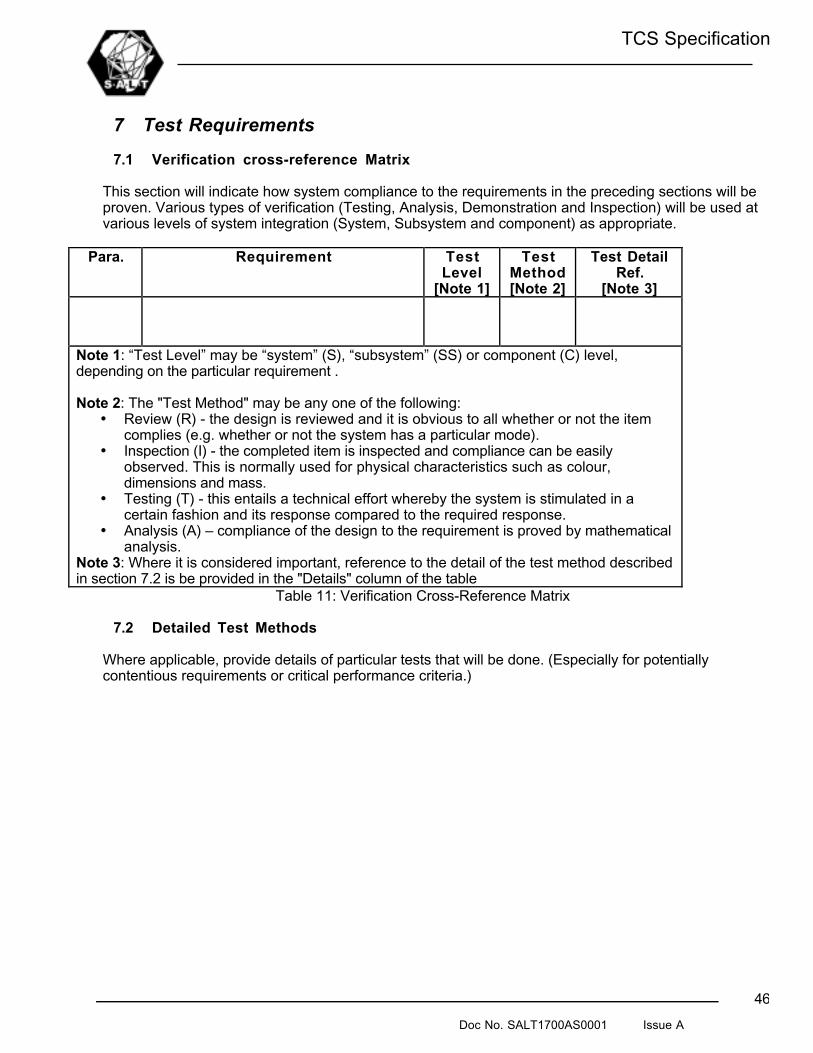
TCS Specification
Doc No. SALT1700AS0001 Issue A
46
7 Test Requirements
7.1 Verification cross-reference Matrix
This section will indicate how system compliance to the requirements in the preceding sections will beproven. Various types of verification (Testing, Analysis, Demonstration and Inspection) will be used atvarious levels of system integration (System, Subsystem and component) as appropriate.
Para. Requirement TestLevel
[Note 1]
TestMethod[Note 2]
Test DetailRef.
[Note 3]
Note 1: “Test Level” may be “system” (S), “subsystem” (SS) or component (C) level,depending on the particular requirement .
Note 2: The "Test Method" may be any one of the following:• Review (R) - the design is reviewed and it is obvious to all whether or not the item
complies (e.g. whether or not the system has a particular mode).• Inspection (I) - the completed item is inspected and compliance can be easily
observed. This is normally used for physical characteristics such as colour,dimensions and mass.
• Testing (T) - this entails a technical effort whereby the system is stimulated in acertain fashion and its response compared to the required response.
• Analysis (A) – compliance of the design to the requirement is proved by mathematicalanalysis.
Note 3: Where it is considered important, reference to the detail of the test method describedin section 7.2 is be provided in the "Details" column of the table
Table 11: Verification Cross-Reference Matrix
7.2 Detailed Test Methods
Where applicable, provide details of particular tests that will be done. (Especially for potentiallycontentious requirements or critical performance criteria.)

TCS Specification
Doc No. SALT1700AS0001 Issue A
47
8 Notes
a. Issue A of this document is for preliminary review and is not suitable for final use.

TCS Specification
Doc No. SALT1700AS0001 Issue A
48
Appendix A: SO Display Information
This data is TBD5
TCS Specification
Doc No. SALT1700AS0001 Issue A
49
Appendix B: SA Display Information
This data is TBD5

TCS Specification
Doc No. SALT1700AS0001 Issue A
50
Appendix C: Common Display Information
This data is TBD5
TCS Specification
Doc No. SALT1700AS0001 Issue A
51
Appendix D: List of TBD’s and TBC’s
The following issues are addressed in this document but require definition (TBD’s – To Be Determined) orconfirmation (TBC’s – To Be Confirmed):
TBD1. These documents have not yet been defined but will be by June 2001. Specific technicalissues will be addressed in an ad hoc fashion as required.
TBD2. The HET planning tools will be used as the basis for SALT. An investigation is in process todetermine modifications that will be required. These requirements will be known bySeptember 2001.
TBD3. The mechanism for synchronisation for time-critical data will be finalised during the detaileddesign process and co-ordinated with the applicable subsystems and Instruments.
TBD4. The requirements for the TCS Simulator will be finalised by Sept 2001.TBD5. The provisional display requirements will be defined after approval of the SALT Operational
Requirements document. This is will be completed by May 2001.
TBC1. The Guidance and Acquisition MMI on the So Workstation is provisionally part of the PayloadComputer software. Some detailed concepts will require review prior to the finalisation ofthis decision.