
TIN KNOCKER TK 1624 & 2024 SLITTER - Sheet Metal Equip
16
1 TIN KNOCKER TK 1624 & 2024 SLITTER INSTRUCTIONS & PARTS DIAGRAM TK 1624 & 2024 SLITTER Sheet Metal Equipment Sales Inc. Dean P. O'Connell, President Green Bay, Wisconsin Phone - (920)-662-9966 Fax - (920)-662-9969 Website: www.sheetmetalequip.com 12/29/04
Transcript of TIN KNOCKER TK 1624 & 2024 SLITTER - Sheet Metal Equip
1
TIN KNOCKER
TK 1624 & 2024 SLITTER
INSTRUCTIONS & PARTS DIAGRAM
TK 1624 & 2024 SLITTER
Sheet Metal Equipment Sales Inc.Dean P. O'Connell, President
Green Bay, WisconsinPhone - (920)-662-9966
Fax - (920)-662-9969
Website: www.sheetmetalequip.com
12/29/04

TIN KNOCKER
SAFETY RULESTK 1624 & 2024 SLITTER
1. WARNING:
Electrical Danger---Misuse or improper installation of machinery connected to a source ofelectricity may result in accidental shock that could cause injury or death. Installation mustconform to National Electric Code (Article 250-Grounding, etc.)
A trained and qualified electrician must make electrical connections. Electrical characteristics shownon motor plate and control panel must match the power source; and all electrically poweredequipment must be grounded.
2. WARNING:Mechanical Danger- The cutting blades of the Slitter rotate at all times when power is supplied to themotor. Never place any part of the body including loose clothing near or onto the rotating rolls. (KEEPHANDS AWAY). Failure to comply will lead to personal body injury. Do not exceed the work-piecematerial capacity–otherwise serious damage will occur to your Slitter.
3. Machine to be operated by authorized personnel who have been trained by their supervisor with theworking and safety features of the machine, and by reading and understanding the Operator’s Manual.
4. Do not operate Slitter without reading Operator’s Manual and without proper supervisoryinstructions.
5. Perform all installation and set-up operations before applying power for electrical start-up.
6. Never operate machine with any guard removed; i.e., all required guarding to be installed andeffective. Do not override the safety features of the equipment. Do not remove, paint over, alter, ordeface any machine-mounted warning and instruction plates and signs.
7. Never leave machine running unattended. When not in use, turn off electrical power.
8. Never adjust machine with power on.
9. Avoid accidental start-up.
10. Do not use machine if servicing is required.
11. Use safety glasses and required protective tools.
12. Keep work areas clean and in proper order.
2
13. Be alert to all potential hazards. Notify your supervisor whenever you feel there is a hazardinvolving the equipment or the performance of your job.
WARRANTYAll new SME machines are sold with a one-year limited warranty, on factory defective parts. The warranty islimited to the original user. SME at its option, will repair, replace or refund the purchase price of any part,tool or machine that fails during the warranty period. SME will pay normal shipping charges forreplacement parts. After 90 days from date of purchase, all express or overnight delivery charges are theresponsibility of the customer. Purchaser must contact SME, at the address below, any written claim, withproof of original purchase. Replacement parts will be invoiced to purchaser and credit issued when the failedpart is delivered to SME. Removal, reinstallation or replacement parts shall be at purchasers’/ user’sexpense. Failure due to improper use of the machine voids the warranty.
NOTE: This machine has been tested and adjusted prior to shipment, but can and often does requirereadjustment due to vibration and bouncing during transport. Readjustment can easily be done by followingthe procedures described within. These are procedures with which you, as a user, should be familiar, as youwill use them repeatedly over the life use of the machine. If you have difficulty in performing theseprocedures, we are here to support you.
Sheet Metal Equipment Sales Inc.Dean P. O'Connell, President
Green Bay, WisconsinPhone - (920)-662-9966
Fax - (920)-662-9969
Website: www.sheetmetalequip.com
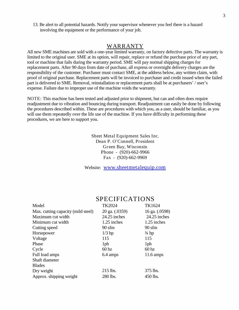
SPECIFICATIONSModel TK2024 TK1624Max. cutting capacity (mild steel) 20 ga. (.0359) 16 ga. (.0598)Maximum cut width 24.25 inches 24.25 inchesMinimum cut width 1.25 inches 1.25 inchesCutting speed 90 sfm 90 sfmHorsepower 1/3 hp ¾ hpVoltage 115 115Phase 1ph 1phCycle 60 hz 60 hzFull load amps 6.4 amps 11.6 ampsShaft diameterBladesDry weight 215 lbs. 375 lbs.Approx. shipping weight 280 lbs. 450 lbs.
3

INSTALLATION INSTRUCTIONS
1. With minimal set-up, your slitter can be put into immediate production.2. After reading the Operator’s manual thoroughly, carefully remove all the packaged parts and
inspect to ensure all the required items were included. Inspect for any damage that may haveoccurred during shipping, if damage is present, immediately contact the carrier responsible.
3. Carefully place the slitter on a bench or on the “optional stand”. DO NOT loosen the clampingknobs (#5 & # 6) until required.
4. Carefully insert the back gauge bar (#1) through the throat of the slitter, the bar’s machined grooveshould face towards the front of the slitter. Align the threaded holes of the back gauge bar with theproper mounting hole/slot of the left housing arm (#2). (See illustration below for proper holes to beused for your slitter model.) Insert the M8-1.25 hex screw, lock washer and the 81.25 shoulder bolt butdo not tighten. NOTE: You will notice a setscrew in the rear portion of the slotted hole. These screwsare used to re-align the back gauge bar to its original set position.
5. Insert the setscrews into the threaded hole (A) and continue turning screw until contact is made withthe shoulder bolt, turn until full contact is made with the rear set screws. DO NOT over tighten.
6. The left side is now properly positioned, the hex screw can now be tightened to 10 ft. lbs. Before theshoulder bolt can be tightened, the front setscrew must be loosened to allow the shoulder bolt to turn.After the shoulder bolt has been tightened, re-tighten the setscrew against the shoulder bolt.
4

IMPORTANT: Your slitter maybe equipped with the cant adjustment screws (#27) which areinstalled in the right housing arm. DO NOT tamper with them until the instructions on “cant adjustment”hasbeen completely read.
7. Loosen both clamping knobs (#5 & #6), then bring together the back gauge bar and the righthousing arm, align the parts, then carefully inspect both parts to insure complete and even contactis being made. (See figures D and F for the types of misalignment possible. This alignment is veryimportant; because if left uncorrected, binding of the parts will occur when final tightening of themounting bolts is attempted.
FIGURE D: Shows the misalignment possible, as viewed from the front of the slitter. (Circled Area.)FIGURE E: If this type of misalignment is not corrected before the mounting bolts are tightened, thenbinding will occur in the areas shown by the two smaller arrows.
5
FIGURE F: Shows the misalignment possible. (Circled Area.)

FIGURE E: If this type of misalignment is not corrected before the mounting bolts are tightened, the backgauge bar will be drawn towards the housing, thus cause the bar to twist and the housing arm to bindagainst the guide shaft.
8. While holding the back gauge bar and right housing arm in proper alignment, insert the hex screwand secure with a flat washer, lock washer and hex nut. DO NOT tighten. Continue holding theparts in position while inserting the shoulder bolt through the slotted holes, then secure with a flatwasher, lock washer and a hex nut. DO NOT tighten.
9. Insert the setscrew into threaded hole, turn until the shoulder bolt is contacted and pushed againstthe “pre-set”set screws. This procedure aligns the back gauge bar back to its original setting.
10. The back gauge assembly should slide along the entire movement range without binding. Clean andlubricate the guide shafts with good slide ways oil. If binding is present, loosen the hex nuts on the righthousing arm until the binding is eliminated.
11. Slide the assembly back and forth while slowly tightening the hex screw and hex nut. If alignment iscorrect, then the assembly should move freely without binding. If binding occurs and assembly won’tmove easily, then see instructions on “CANT ADJUSTMENT”.
12. Install the scrap guide to the left side of the slitter and secure with the pin. Attach the spring to the cotterpin, which protrudes through the side of the slitter.
13. Connect to the proper electrical receptacle and then turn o slitter. Allow running without a load for a fewminutes, and then turning off. Set back gauge for a 3 inch wide cut, then slit a small sample, measurethe piece for accuracy. Set the scale pointer to the Actual measured width, if necessary.
CANT ADJUSTMENT:NOTE: If the back gauge bar “loading angle”is correct, but the assembly will not move freely, follow theseinstructions to correct problem.
1. DO NOT loosen any of the bolts of the left housing arm.2. Loosen both clamp knobs. Inspect, clean and lubricate the guide shafts prior to adjustments.3. Remove the hex nuts from the right housing arm ONLY. Loosen the front setscrew away from
the shoulder bolt. REMEMBER NOT to move the rear set screws as they determine the correctposition of the back gauge bar when final adjustments are performed.
4. If equipped with cant adjustment screws back them off until they do not protrude below the partsurface.
5. The back gauge bar should detach from the housing arm. (remove any burrs visible on the back gaugebar before continuing.) Both part surfaces should be clean of any burrs or foreign matter, as theirpresence may hamper the alignment procedure.
6

6. Return the back gauge bar to its original position, making certain that both part surfaces are makingfull contact with each other. Install the hex nuts back onto their respectable bolts. DO NOT tightencompletely.
7. Inspect parts for any possible misalignment. If any are visible, determine the type present. Correctmisalignment by inserting the cant adjustment screws in the area of the misalignment, gap causedby the misalignment.
8. Turn the front set screw until it contacts the shoulder bolt. This procedure will return the back gaugebar to its original position.
9. The back gauge assembly should move freely through the entire movable range.
10. While moving the back gauge assembly back and forth, slowly tighten the hex nuts in smallincrement. If binding occurs before the nuts are fully tightened, STOP turning or turn back the nutsto the point where the binding first occurs. Slowly turn in both cant adjustment screws in small andequal increments until the assembly frees-up and moves easily again.
7

BACK GAUGE BAR LOADING ANGLE
Setting up and adjusting the back gauge bar, as described below, is so accomplished to run the “line of cut”,(which is parallel to the back gauge bar’s machined groove), approximately midway through the “bladedivergence angle”. The action of the top blade when slitting causes a very slight load to be put on the sheetbeing slit, thus holding the sheet in the back gauge’s groove. This helps the operator in keeping the sheetagainst the back gauge bar during the entire slitting process, thus resulting in a straight cut.
1. Slide back gauge assembly to 3”on the scale, and then tighten both knobs.2. Remove the top blade cover and the top cutting guide. Place a precision straight edge against the
face of the top blade Important: the straight edge must be held against the top blade or thisadjustment will be incorrect!
3.While holding the straight edge in place (assistance in this procedure would be helpful), starting at the farleft hand side of the back gauge bar, measure the distance from the straight edge to the back gauge bar’smachine groove.
4.Using the same procedure, measure the far right hand side of the back gauge bar. When correctly set, theright side measurement is (.0312”) more than the left side measurement. This adjustment accomplishesthe back gauge loading angle. Should this angle be too great, it will result in buckling of lighter materialor the stalling or dragging of the material being slit.
If this angle should be less than required, the material can possibly wander or pull away from the backgauge bar, thus resulting in an uneven or narrow cut.
8
5. If re-adjusting is required, follow the instructions below.
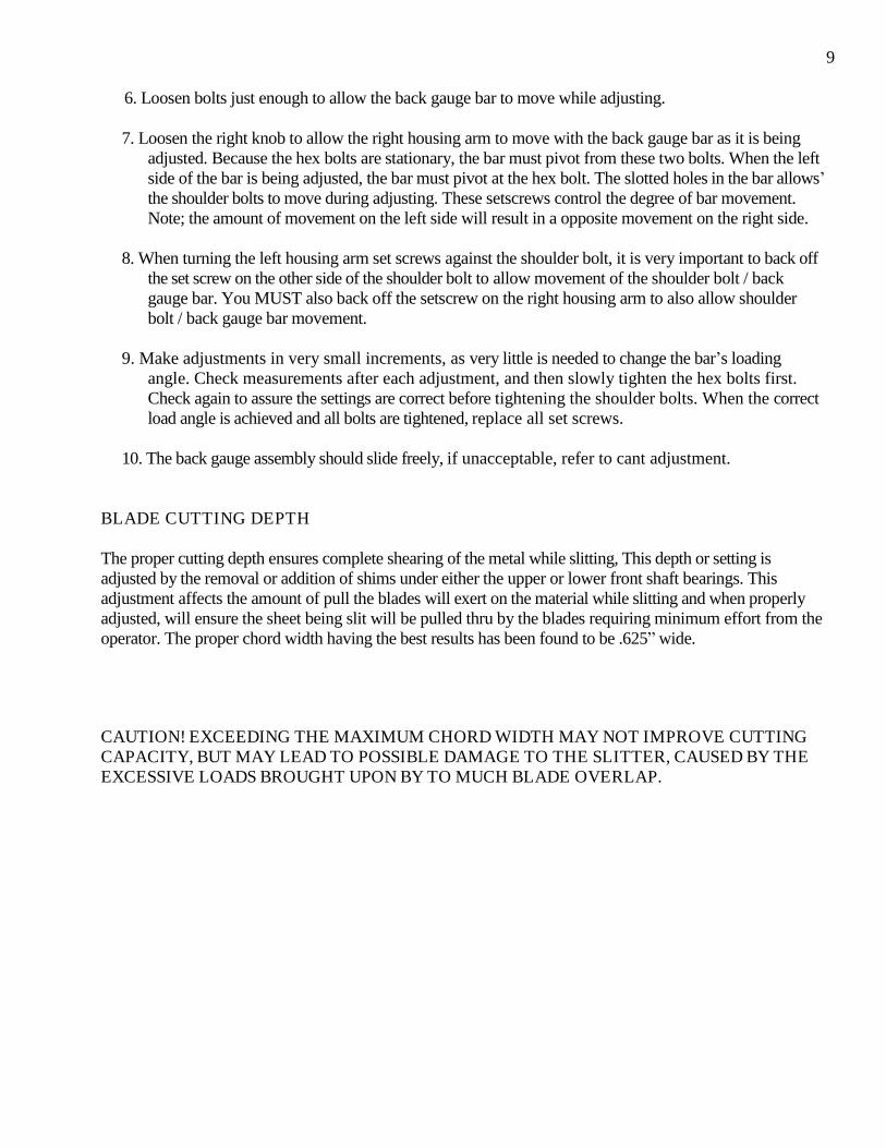
6. Loosen bolts just enough to allow the back gauge bar to move while adjusting.
7. Loosen the right knob to allow the right housing arm to move with the back gauge bar as it is beingadjusted. Because the hex bolts are stationary, the bar must pivot from these two bolts. When the leftside of the bar is being adjusted, the bar must pivot at the hex bolt. The slotted holes in the bar allows’the shoulder bolts to move during adjusting. These setscrews control the degree of bar movement.Note; the amount of movement on the left side will result in a opposite movement on the right side.
8. When turning the left housing arm set screws against the shoulder bolt, it is very important to back offthe set screw on the other side of the shoulder bolt to allow movement of the shoulder bolt / backgauge bar. You MUST also back off the setscrew on the right housing arm to also allow shoulderbolt / back gauge bar movement.
9. Make adjustments in very small increments, as very little is needed to change the bar’s loadingangle. Check measurements after each adjustment, and then slowly tighten the hex bolts first.Check again to assure the settings are correct before tightening the shoulder bolts. When the correctload angle is achieved and all bolts are tightened, replace all set screws.
10. The back gauge assembly should slide freely, if unacceptable, refer to cant adjustment.
BLADE CUTTING DEPTH
The proper cutting depth ensures complete shearing of the metal while slitting, This depth or setting isadjusted by the removal or addition of shims under either the upper or lower front shaft bearings. Thisadjustment affects the amount of pull the blades will exert on the material while slitting and when properlyadjusted, will ensure the sheet being slit will be pulled thru by the blades requiring minimum effort from theoperator. The proper chord width having the best results has been found to be .625”wide.
CAUTION! EXCEEDING THE MAXIMUM CHORD WIDTH MAY NOT IMPROVE CUTTINGCAPACITY, BUT MAY LEAD TO POSSIBLE DAMAGE TO THE SLITTER, CAUSED BY THEEXCESSIVE LOADS BROUGHT UPON BY TO MUCH BLADE OVERLAP.
9
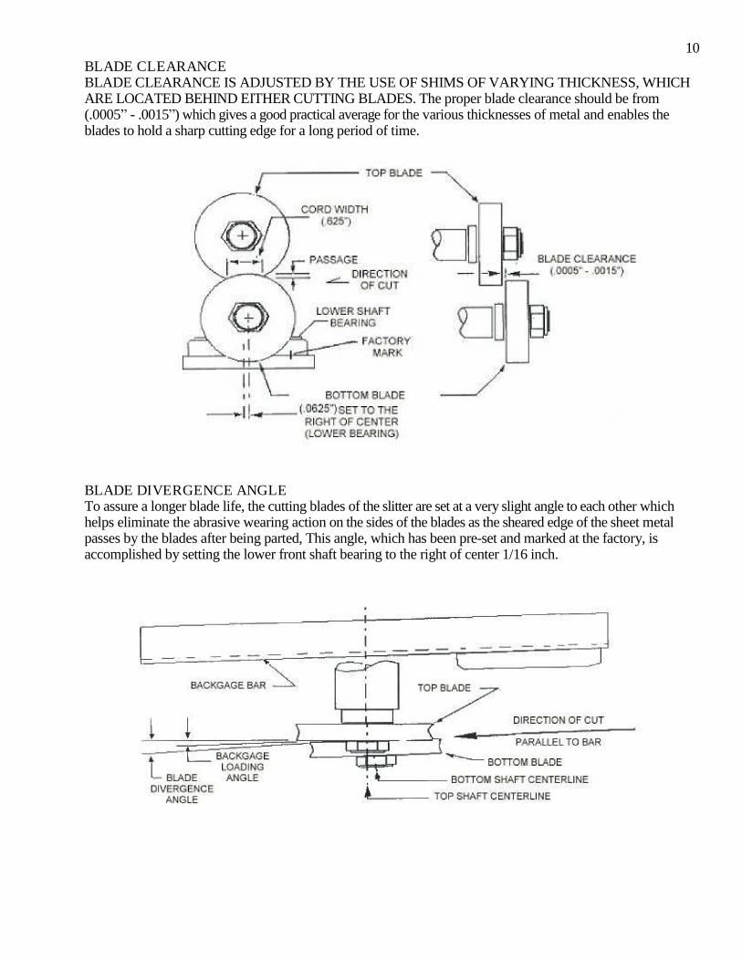
BLADE CLEARANCEBLADE CLEARANCE IS ADJUSTED BY THE USE OF SHIMS OF VARYING THICKNESS, WHICHARE LOCATED BEHIND EITHER CUTTING BLADES. The proper blade clearance should be from(.0005”- .0015”) which gives a good practical average for the various thicknesses of metal and enables theblades to hold a sharp cutting edge for a long period of time.
BLADE DIVERGENCE ANGLETo assure a longer blade life, the cutting blades of the slitter are set at a very slight angle to each other whichhelps eliminate the abrasive wearing action on the sides of the blades as the sheared edge of the sheet metalpasses by the blades after being parted, This angle, which has been pre-set and marked at the factory, isaccomplished by setting the lower front shaft bearing to the right of center 1/16 inch.
10

TROUBLESHOOTING
PROBLEMS PROBABLE CAUSE SOLUTION
Wavy oruneven cuts
Insufficient back gauge loadingangle Sheet material edge notstraight Sheet sagging during slittingDamaged blade edges Worn groovein back gauge bar
Check and set to specifications Inspectprior to slitting Support sheet withtables Inspect, repair if neededCheck with straight edge; replace
Light gaugemetals buckleor strip hangsup after slitting
Excessive back gauge loading angleImproper support of sheet duringslitting
Check and decrease load angle Supportsheet with tables
Score marks onmaterials afterslitting
Excessive blade overlapCutting guide height improperly setScrap guide improperly set Incorrectblade type
Check for proper overlap 5/8 cordInspect and adjust if necessary Inspectand adjust if necessary
Small piecescatches on barand pivotsaround
Excessive back gauge loading angleSheet too smallBad spot in bar’s grooveCorner of sheet hangs-up ingroove’s bad spot
Check and decrease load angle Avoid ifpossible Inspect and repair Grind or fileoff sharp corner
Sheet hard tostart
Material exceeds machine’s capacityExcessive blade overlap Feed heightalignment incorrect Oil on bladesurface
Check thickness prior to slitting Checkand decrease if necessary Sheet shouldfeed as level as possible Inspect andclean
Motor runs, butblades do notrotate
Loose v-beltSheared or damaged key in gearsMotor pulley loose Damaged teethin gears
TightenInspect and repairInspect and tighten set screw.Inspect and replace
Motor stalls orstops
Defective wiringIncorrect voltage Defectivemotor/overheats Exceeding capacityof machine
Inspect by qualified technician Testfor proper voltage and wiring Inspectand replace Stay within machine’scapacity
Blades do notpull sheetduring slitting
Pre-painted type sheetsOil on bladesExcessive back gauge loading angleExcessive drag improper set-up
Keep blades clean and dryInspect and clean Check and decrease.Lubricate bar groove, support sheetproperly, minimize sheet sagging anddrag.
1112

TROUBLESHOOTING
PROBLEMS PROBABLE CAUSE SOLUTION
Incompletecut/won’t cutthru material
Exceeding machine capacityDull blades/ improper clearancesInsufficient blade over-lapMaterial too hard
Check thicknessReshape blades / adjust to properclearancesInspect and adjust to specificationsCheck material’s hardness
Excessive edgeburrs or rollededges
Dull bladesExcessive blade clearancesSoft materials
Reverse bladesAdjust to specificationsDecrease overlap, set blade clearanceto the minimum and keep sharp bladeedges.
Excessive endplay in driveshafts
Loose set screws in shaft bearingsworn shaft bearings
Inspect and tighten Inspect / replace
Back gaugeassemblybinds, won’tslide freely
Misalignment of parts when re-assembled or adjusteddry, dirty and / or damaged 1”guideshafts
See cant adjustmentInspect, clean and lubricate with oil
Excessivenoises whenoperating
Loose v-belt / rubbing or guard coverDry pulley and cluster gear assembliesForeign object in gear teethDry gear teethV-belt over tightenedLoose motor pulleyDefective motorBlades rubbing against each other10”pulley or cluster gear assemblydoes not spin freelyMotor mounts looseMotor mount plate not adjustedevenly
Inspect and tightenGrease via fittings at ends of shaftsCheck for damage and removeLubricate AdjustInspect and tighten set screw Inspectand replaceInspect and correctGears must spin freely on the shaftsCheck for clearance between theassemblies and the retainer washersTightenCheck for warpage of the mountingplate

MAINTENANCE
Keep blades clean and properly adjusted to ensure quality cuts.
Lubricate motor per manufacturer’s recommendations. Check v-
belt for proper tension, do not over tighten.
Remove slitter’s rear cover panel and apply grease to the grease fittings on the end of each drive shaft.
Keep guide shafts clean and well lubricated.
Never slit materials of greater capacity, damage to the slitter may occur. Keep
your slitter properly maintained and adjusted.
13

14

1 SLIT00001 Linear motion Back gauge bar 12 SLIT00002 (L) Housing arm assy.- 13 SLIT00003 (R) Housing arm assy.- 14 SLIT00004 Pointer assembly 15 SLIT00005 (L) Clamp knob –[2”] 16 SLIT00006 (R) Clamp knob- [2”] 17 SLIT00007 Back gauge material shelf –14 18 SLIT00008 1”guide shafts- (33”) 29 SLIT16009 ( R) shaft blocks- 1624 29 SLIT20010 ( R) shaft blocks- 2024 210 SLIT16011 (L) shaft blocks- 1624 210 SLIT20012 (L)shaft blocks- 2024 217 SLIT00013 Scrap guide mounting brackets 218 SLIT20014 2024 (T) blade cover 118 SLIT16015 1624 (T) blade cover 119 SLIT20016 2024 (B) blade cover 119 SLIT16017 1624 (B) blade cover 121 SLIT00018 30”scale 122 SLIT16019 Material belly pan –1624 122 SLIT20020 Material belly pan –2024 124 SLIT00021 Housing arm brushings –1.25”(od) x 1”(id) 436 SLIT16022 (T) 1624 shafts –1.5”dia. 1

16PARTS LIST
ITEM PART # ITEM DESCRIPTION QTY.
37 SLIT16023 (B) 1624 shafts –1.5”dia 140 SLIT00024 On/off toggle switch 160 SLIT00025 “Blade”Jam nut 261 SLIT00026 (Std) 4”double edge blades 262 SLIT00027 Blade collars 263 SLIT00028 Blade key- ¼”x ½”sq. 264 SLIT00029 Shaft main bearings–1”bore 466 SLIT20030 (T) 2024 shafts–1.25”dia. 167 SLIT20031 (B) 2024 shafts –1.25”dia. 170 SLIT00032 48T Equil. Gear 271 SLIT00033 Gear shims (.0625”) 372 SLIT00034 66T drve gear 173 SLIT00035 Cluster gear assy. 66T x 30T 174 SLIT00036 10”Pulley assy. W/ 30T gear 175 SLIT00037 Retainer washer–¼”x 1 ¼” 277 SLIT00038 ¼-28 grease fitting 287 SLIT20039 2024 motor guard assy. 187 SLIT16040 1624 motor guard assy. 188 SLIT20041 2024 motor–1/3 hp 188 SLIT16042 1624 motor–¾ hp 189 SLIT20043 2024 motor pulley (3x900) 189 SLIT16044 1624 motor pulley (3 x 901) 190 SLIT20045 v-belt (4L360) 190 SLIT16046 v-belt (4L390) 192 SLIT00047 8ft. supply cord 193 SLIT00048 Scrap guide body (only) 194 SLIT00049 S.G. Pin 195 SLIT00050 S.G. Spring 196 SLIT20051 Cutting guides–2024 296 SLIT16052 Cutting guides–1624 298 SLIT00053 Shaft bearing set screws 8
SLIT20054 Frame 2024 1SLIT16055 Frame 1624 1


![Perchta Belly Slitter[1]](https://static.fdocuments.in/doc/165x107/545a8917b1af9f4a1d8b4996/perchta-belly-slitter1.jpg)