Timmins, Ontario A. Watts December 1979 Geophysicist
19
42A89SEW38 Z , 3398 MCCOOL 010 REPORT ON AN AIRBORNE ELECTROMAGNETIC AND MAGNETIC SURVEY MATHESON CLAIMS MCCOOL-l PROJECT 839-02 AMAX OF CANADA LIMITED Timmins, Ontario Timmins, Ontario A. Watts December 1979 Geophysicist
Transcript of Timmins, Ontario A. Watts December 1979 Geophysicist
42A89SEW38 Z , 3398 MCCOOL 010
REPORT ON
AN AIRBORNE ELECTROMAGNETIC
AND MAGNETIC SURVEY
MATHESON CLAIMS
MCCOOL-l
PROJECT 839-02
AMAX OF CANADA LIMITED Timmins, Ontario
Timmins, Ontario A. Watts
December 1979 Geophysicist
SUMMARY
A detailed, radar navigation controlled, helicopter electro magnetic survey, performed by Aerodat Limited for Amax of Canada Limited in April 1979, has outlined a long, "formational-type" conductor which has already been tested by drilling.
No ground follow-up of this conductor is therefore recommen ded.
I. INTRODUCTION
During the period between April 10 and April 19, 1979, Aero- dat Limited carried out a combined helicopter-borne, radar-controlled electromagnetic and magnetic survey over 16 claims in McCool township for Amax of Canada Limited.
The purpose of the survey was to follow-up in detail, con ductive zones of interest previously located by a regional INPUT A.E.M. survey over the area.
II. PREVIOUS EXPLORATION
Observed in Field:
Old claim posts representing four generations of staking dating back to 1962 were seen, but no old drilling sites or grids were seen. No evidence remains of several old trenches indicated by Satterly (1952).
Assessment Files:
Abstracts of work filed on the above mentioned claims indicate that only one of the four generations of staking had any work recorded for them, it being forty days of unspecified grouped work done on claim L-76717.
Additional information taken from the compilation maps of work filed with the mining recorder's office, and from Roussain (1978) indi cate the following past work:
- various work by difference companies (including drilling) in exploration for asbestos in the ultramafic bodies which surround the property (dating back to 1950)
- A.E.M., V.E.M. and drilling by Area Mines (1963) on a V.E.M. conductor, to the east of the present claim L-499483
- magnetometer, V.H.E.M., H.E.M. and gravity surveys, anddrilling in the four claims in the south entrance (L-499481to L-499484), by Texasgulf Sulphur Company (in 1972)
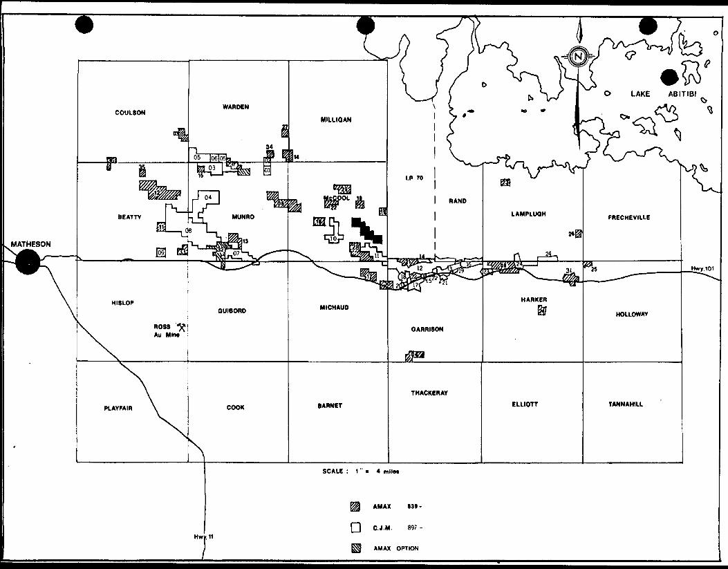
O LAKE ABITIBI
AMAX (39
Q C.J.M, 897
AMAX OPTION
fer
525761
LOT H
I
5*5764-
525765
5X5787
525766
525768 52578*)
525790
LOT LOT Z LOT l
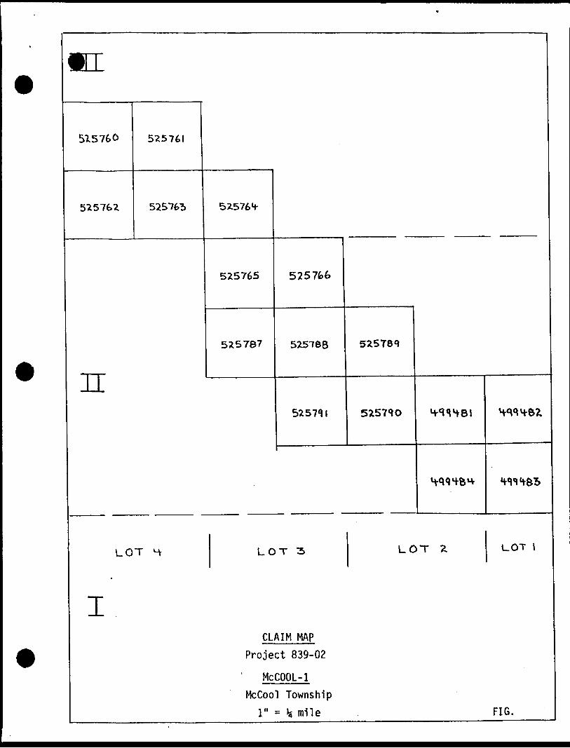
CLAIM MAP
Project 839-02
McCOOL-l
McCool Township
l" = * mile FIG.
III. GEOLOGY
Genera1 Geol ogy:
McCool Township lies in the central part of the Abitibi Green stone Belt, The most striking features of the geology of the area is a large isoclinally folded syncline to the west of the property, well de fined by outcrop and drill sections of ultramafic rock; the Destor- Porcupine Fault Zone, approximately 8 km to the south of the property; and a smaller less well defined anticline (defined by pillow top direc tions in mafic volcanic rocks) just to the east of the property. A horizon of felsic volcanic rocks strikes northwest-southeast from Gar rison township and Abitibi Indian Reserve NO. 70, through the southeast corner of McCool township towards the claim group, but is not clearly traceable into the property, (from Satterly, 1952).
Property Geology:
Moderately good exposure scattered over most of the property gives a fair idea of the geology here. The rock types seen include felsic to mafic volcanic rocks (flows and pyroclastics) and ultramafic rock (of uncertain origin).
In the northwest of the property, the rock is andesite, occur ring in pillowed, massive and amygdaloidal forms. There is local devel opment of chlorite as dark phenocrysts up to 2-3 mm, which may be a form of wall rock alterations or due to the low grade regional metamorphism which has occurred. A chert horizon about 10 cm thick was noted, con formable with the general bedding direction of the pillows (i.e., about 1200 - 1350 ).
In the central part of the property, the rock is predominantly gabbro and anorthosite gabbro, medium to coarse grained (3mm - lcm cry stals), and variably sericitized. Volcanic rocks occur in the south of claim L-525791, consisting of pillowed and massive andesite (concordant with the andesite in the northwest) and a thin (less than 3m) band of intermediate to felsic pyroclastic rock. Felsic clasts up to 10-12 cm were seen, set into a finer, less felsic matrix.
The southeast part of the property was not investigated in the present survey, but Roussain (1978) indicates the presence of gabbro and
felsic to mafic volcanic flows and pyroclastics (rhyolite and rhyolitic tuff, dacite and andesite).
The property crosses the southwest limb of the above mentioned minor isoclinal anticline, which strikes northwest-southeast and closes to the north. Tops on this limb are to the south, as defined by pillowed andesite flows. The structure appears to be faulted across the strati graphy. Although no actual fault zones were seen due to insufficient exposure, their presence is inferred from the following data: the off set of the chert horizon in claim L-525764; the offset of lithology contacts in the southeast (between gabbro and volcanic rock); and the presence of felsic tuff in claim L-525791, posssibly faulted to the south where it over lies.
No mineralization was seen on the property, except for dissemi nated minor pyrite in the andesites.
- 4 -
IV. SURVEY EQUIPMENT AND PROCEDURES
Survey equipment consisted of a dual frequency Aerodat/Perle electromagnetic system operating at 915 Hertz and 3800 Hertz, a Barringer AM-104 proton precession magnetometer, a Motorola Mini-Ranger III position ing system (MRS III), an Aerodat-Perle navigational guidance and data ac quisition system, a Hoffman radar altimeter, a Geocam 35 mm flight path camera, and a Barringer 8-channel analogue recorder. This system was installed in a Bell Jet-Ranger helicopter.
The survey was flown at a line spacing of 125 metres. Survey airspeed averaged about 70 mph, and the aircraft maintained an average terrain clearance of 235 feet, with the magnetometer sensor located on a tow cable 50 feet below the aircraft and the EM bird 100 feet below, or approximately 135 feet above the ground.
Survey navigation was controlled by an MRS III positioning system. The MRS III, operating on the basic principle of pulse radar, uses a transmitter (located in the aircraft) to interrogate the reference station transponders. The elapsed time between the transmitted interro gation produced by the transmitter and the reply received from each trans ponder is used as the basis for determining the range to each transponder. This range information, displayed by the MRS III together with the known location of each transponder, is trilaterated to provide a position fix of the helicopter. The MRS III operates at line-of-sight ranges up to approximately 39 kilometers and, with appropriate calibration, the prob able range measurement accuracy is better than 3 metres (10 feet).
Processing of the range information is automatically accomplished by microprocessor in the DAC-NAV system to produce a flight-line direction, distance along the flight-line and deviation from proposed line. On com pletion of a proposed line, the guidance system indicates a turn and the next line at a predetermined line spacing.
MRS III range information is recorded digitally on tape and is subsequently computer processed and plotted to produce maps showing the actual flight-path. Flight-path was also recorded manually by the operator- navigator, and automatically by a 35 mm Geocam sequence camera.
Aerodat personnel involved in the survey were:
W. P. Boyko Party chiefFraser Skoreyko Field assistantE. B. Morrison Systems consultantJohn Hall Pilot
6 -
V. DATA REDUCTION AND PRESENTATION
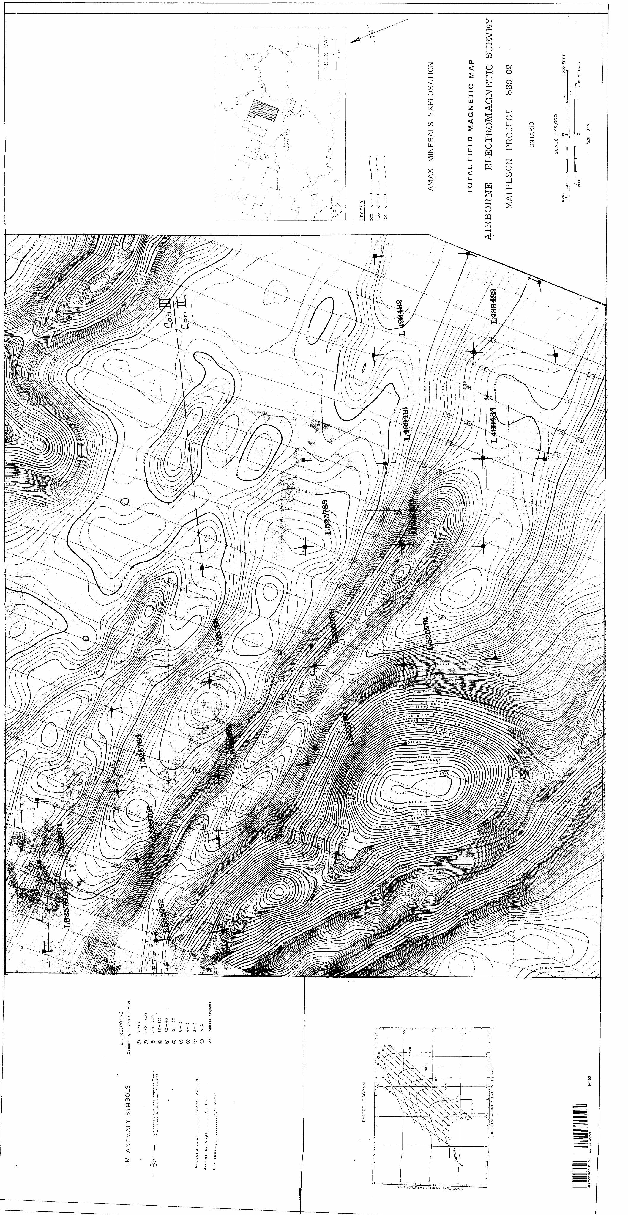
The airborne EM survey and results, together with a location map, are presented in Figure l at a scale of 1:5000.
Initially, a flight-path map was created from the edited and smoothed MRS III data. Manual fiducials recorded over recognizable terrain features are shown, together with principal topographic features and the claim boundaries.
The in-phase and quadrature EM readings (at the 915 Hertz fre quency) are then plotted as profiles along each flight-line, using a vertical scale of l ppm of the primary field equal to 3 mm. The zero level for each trace is set using the background observed at the end of each line.
The locations of significant anomalous responses are shown as a circle, with the in-phase amplitude displayed in ppm and the computed apparent conductivity-thickness shown by a graphic representation.
It should be noted that the apparent conductivity-thickness (at) is computed using the phasor diagram for a narrow vertical dike of infinite extent in free space, shown as an inset in Figure 1. The re lationship of apparent at to the true value depends upon how closely the body approximates a sheet-like form, and upon how nearly at right angles its strike direction is to the flight-line of the aircraft.
For ease of comparison, the derived conductivity-thickness value is divided into 10 ranges (as shown on the map legend) and the range (rather than the actual value) is indicated graphically on the AEM map. While high conductivity-thickness values are generally associated with good bedrock conductors such as graphite or massive sulphides and low values with overburden sources, anomaly amplitude, shape and persis tence are equally important in the subsequent evaluation of the AEM ano malies.
Individual zones of interest have been outlined and numbered. The interpreted axis of a particular conductor is indicated by heavy dashed lines.
VI. DISCUSSION OF RESULTS
Magnetics
The magnetic contour map on this claim group is dominated by a northwest trending linear feature of approximately 600 gammas above background which extends from flight-line 18 to 6 and appears to define the northern boundary of a succession of highly magnetic ultra-mafic units extending at least l km to the south. Relatively low magnetic relief to the north of the above mentioned contact probably indicates the presence of a succession of low susceptibility volcanic horizons.
Electromagnetic Survey
The Aerodat Zone 5-C survey block was laid out to cover in detail a 3 km conductive zone previously located by a Questor INPUT survey.
The present survey has accurately outlined the conductor, whose conductivity improves markedly towards its eastern extremity.
Though only a single conductor is plotted on flight lines 23 to 7, closer inspection of flight records indicate that the anomaly shape is broad in most cases with a hint of double peaking, so that a second conductive source is inferred. The twin source becomes quite obvious from line 6 eastward where conductivity is higher. It is this portion of the conductive trend which has previously been drilled by Texasgulf and Area Mines. Both conductors were drilled, and graphitic argillite with minor pyrite and pyrrhotite were found to be the source in both cases.
VII. CONCLUSIONS AND RECOMMENDATIONS
This long "formational-type" conductive trend has already been evaluated by drilling and found to have a sedimentary source.
No further work is recommended.
Respectfully submitted,
Timmins, Ontario A. H. Watts, B. Se. December 1979 Geophysicist
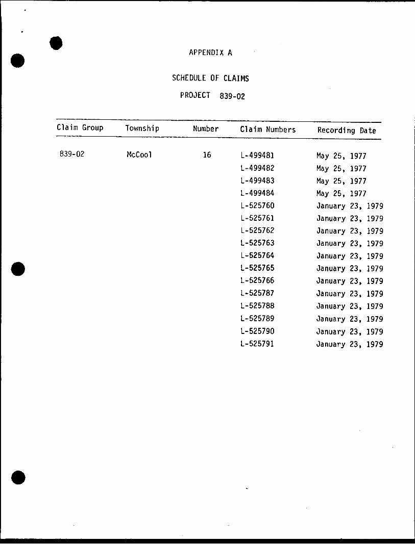
APPENDIX A
SCHEDULE OF CLAIMS
PROJECT 839-02
Claim Group Township Number Claim Numbers
839-02 McCool 16 L-499481L-499482L-499483
L-499484
L-525760L-525761
L-525762L-525763
L-525764L-525765L-525766L-525787L-525788
L-525789
L-525790L-525791
Recording Date
May 25, 1977May 25, 1977May 25, 1977May 25, 1977January 23, 1979January 23, 1979January 23, 1979January 23, 1979January 23, 1979January 23, 1979January 23, 1979January 23, 1979January 23, 1979January 23, 1979January 23, 1979January 23, 1979
tario
Ministry of Natural Resources
GEOPHYSICAL - GEOLOGICAL - GEOCHEMICAL TECHNICAL DATA STATF.MFMT
File.
TO BE ATTACHED AS AN APFACTS SHOWN HERE NEED
TECHNICAL REPORT MUST CONTAII42A89SE8038 2 .3298 MCCOOL 900
yi*
Type of Sui Township o Claim Hold
Survey Con- Author of F Address of Covering Di
Total Miles
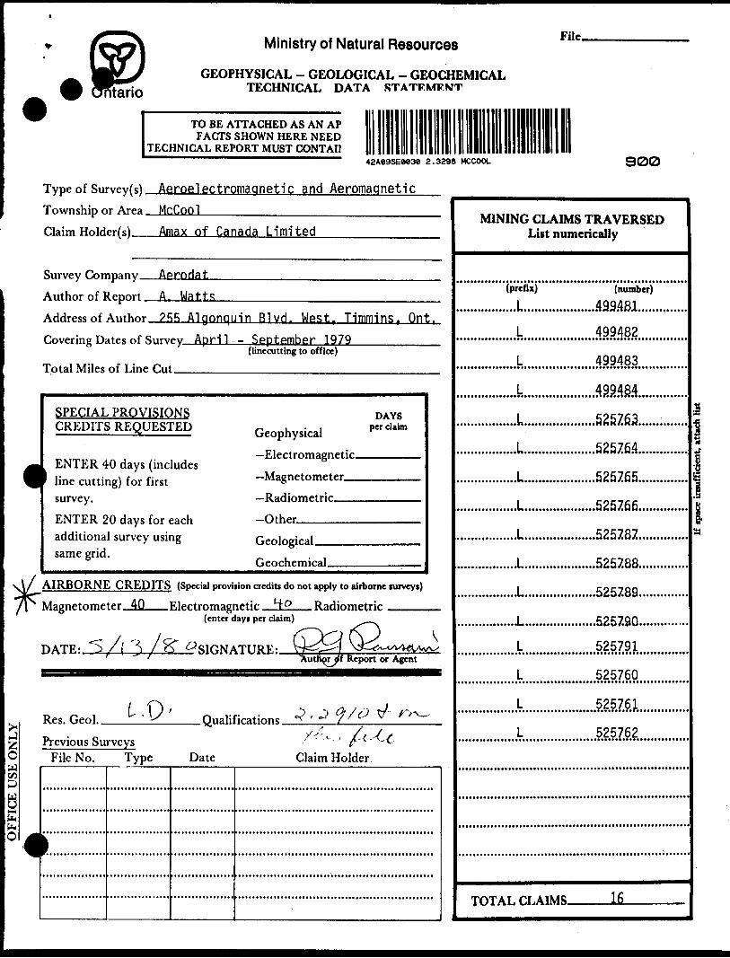
vey(s) Aeroelectromaanetlc and Aeromaqneticr Area McCool
er( s) Amax of Canada Limited
ipany AprndatLeport A, WattsAuthor ?RR Alaonouin Blvd. West. Timmins. Ont.ites of Surv
of Line Cut
Ry April
SPECIAL PROVISIONS CREDITS REQUESTED
1 ENTER 40 days (includes line cutting) for first survey. ENTER 20 days for each additional survey using same grid.
(
AIRBORNE CREDITS Magnetometer 40
DATE: "5, . ,, ,A ^ 1*
Res. Geol.
(Special provi
Electromagt(enter t
f ^STfiNA
- September 1979(linecutting to office)
DAYS ~ i-i per claimGeophysical— V.]rrtrr\magnptir
— WngnPinmrtpr
—Radiometric. ..,...,.-..-Othernipnlnprjral
Geochfmical ,,,....
sion credits do not apply to airborne surveys)
iptir HO RaHinmctrirays per claim)
(DO( 6^ v,TIT1?F.' Vr^r — •"l ^3— <;tJtA/^A^A^Autno^yf Report or Agent
\ i\~\ - . *j^ ' \S ' O iialifiratinns 3 ' ^ ?/^ ^ *~*^
Previous SurveysFile No.
c:::
Type Date Claim Holder
MINING CLAIMS TRAVERSEDList numerically
(prefix) (number)................L....................499.4&L............
L 499482
L 499483
L 49948.4
,,,,,,,,L...................525763.............................L...................52576.4.............
...1 ....... ...........525765.............,...............L...................525766.............
......,......,.L...................525787..............
.................L....................5257.88..............
.................L....................5257.89..............
.................L....................52579Q.............. L 525791L 525760
L 525761
L 525762
IO1AL CLAIMS ————— *M —————— —
iH•f
lH
GEOPHYSICAL TECHNICAL DATA*
GROUND SURVEYS -- If more than one survey, specify data for each type of survey
Number of Stations -^^—^^—^——————^^^————————^Number of Readings —
Station interval ____________________________Line spacing ——^^Profile scale ^^^^^^..^^..^^—^^.^—^^—^^^^^^..^.^.^.^^^^^^^^^^.^^^^,^^^.Contour interval.
O
uszO
O e* H
W
Instrument .Accuracy — Scale constant.
Diurnal correction method.Base Station check-in interval (hours)- Base Station location and value ^—^—
InstrumentCoil configuration .———-——.^——^——^-—-^-^^^——^^——-...-—..—..—-—.——^^.^—......—.—^^-^—
Coil separation _____________________________________________________———— Accuracy ________________________________________________________—^——— Method: d Fixed transmitter d Shoot back d In line d Parallel line
Frequency_________________.____(specify V.L.F. station)
Parameters measured.
Instrument.Scale constant.Corrections made.
Base station value and location .
Elevation accuracy.
[NDUCED POLARIZATION
RESISTIVITY
InstrumentMethod DParameters —
Power
Electrode am Electrode soa
Time DomainOn timr
Off time
TVlay timr-
Integration time
iy ————————————————————ri rip
[~1 Frequency Domain FrequencyRange
Type of electrode
SELF POTENTIAL
Instrument.________________________________________ Range.Survey Method .——————^—-^—-———^^——————-^^————^-————^————.
Corrections made.
RADIOMETRIC
Instrument.Values measured.Energy windows (levels)^—-————.—-..^———^.——....—.^—....——™.—^—..———Height of instrument____________________________Background Count. Size of detector————————^———---^———-—-————.——-————.—-———Overburden .-———————-—————————-—-—————————..——————————
(type, depth - include outcrop map)
OTHERS (SEISMIC, DRILL WELL LOGGING ETC.) Type of survey———————————————————————Instrument ̂ ———^—^——————————————Accuracy-—————————————^^—~———————Parameters measured.
Additional information (for understanding results).
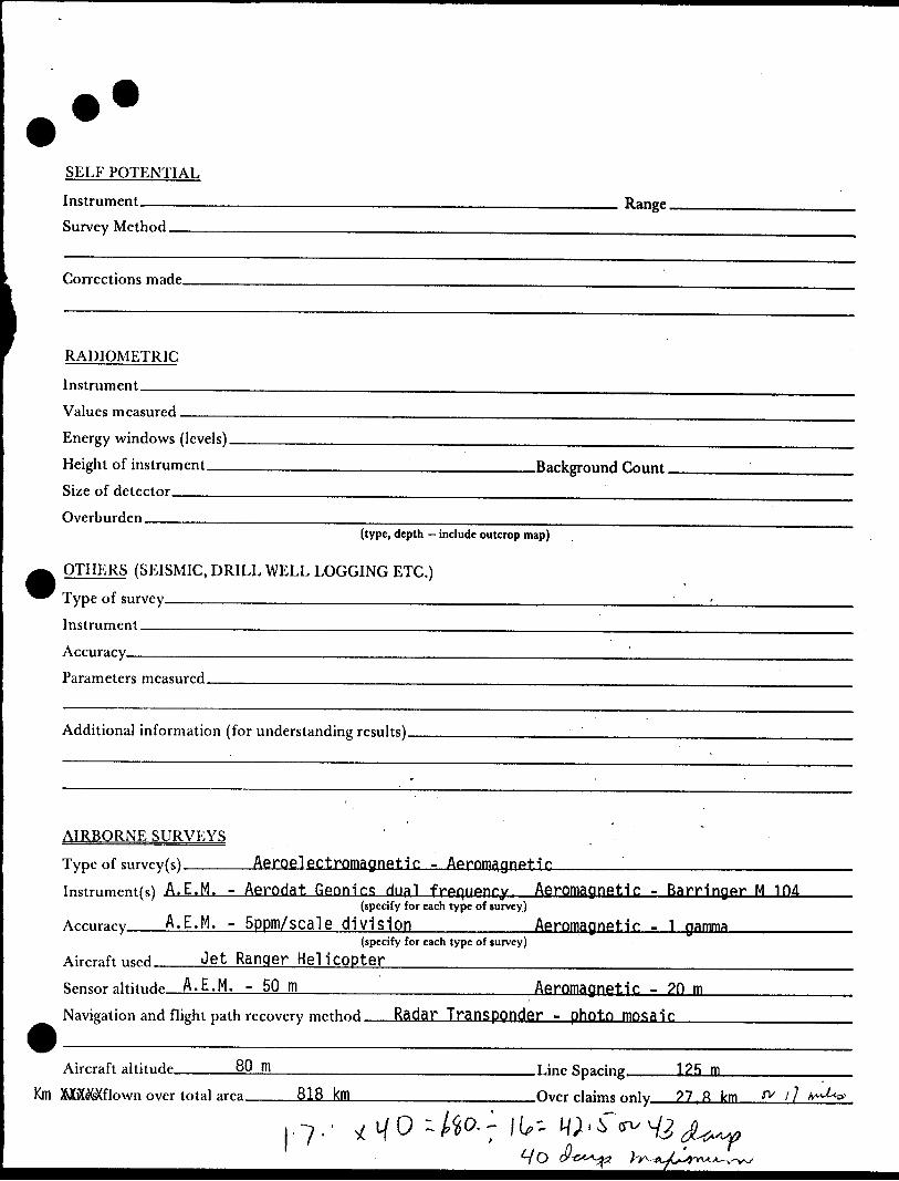
AIRBORNE SURVEYS
Type of survey(s)____AerQelectromagnetic - AftrnmagnFit.lr.Instrument(s) A.E.M. - Aerodat Gennirs dual frpqupnry Aeromagnetic - Bam'naftr M 104
(specify for each type of survey)A.E.M. - Sppm/SCdlG division_____Aeromagnetic - 1 gamma——————
(specify for each type of survey)Aircraft"^ Jet Ranger Helicopter_____________________________ Sensor aU'U^** A.E.M. - 50 m_________________Aeromagnetic - 2Q m—^-————
Airrraft altitiirip 80 m
Mff^flnwn nvrr tntal ar^ 818 km
Tine Sparing,
Over rlaims only
1?B m
?7 ft lcm fV 1 ] A**-^**
7 ..
GEOCHEMICAL SURVEY - PROCEDURE RECORD
Numbers of claims from which samples taken.
Total Number of Samples. Type of Sample.
(Nature of Material)Average Sample Weight——————— Method of Collection————————
Soil Horizon Sampled. Horizon Development. Sample Depth———.— Terrain————————
ANALYTICAL METHODSValues expressed in: per cent
p.p. m. p. p. b.
Dn n
Cu, Pb,
Others—
Zn, Ni, Co, Ag, Mo, As.-(circle)
Field Analysis (-
Drainage Development____________ Estimated Range of Overburden Thickness,
Extraction Method. Analytical Method- Reagents Used——
Field Laboratory AnalysisNo. —————————
SAMPLE PREPARATION(Includes drying, screening, crushing, ashing)
Mesh size of fraction used for analysis ———
Extraction Method. Analytical Method - Reagents Used-——
Commercial Laboratory (- Name of Laboratory— Extraction MpthnH
Analytical Method ——Reagents Used—.——
.tests)
.tests)
.tests)
General- General .
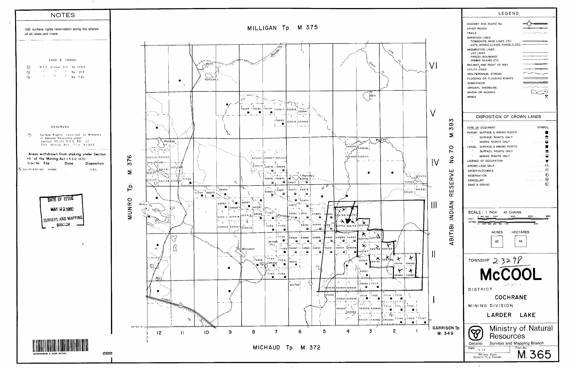
NOTES
400' surface rights reservation along the shores of all lakes and rivers,
SAND 8 GRAVEL
M. T C Gravel Pit Mo 1 56 5
" " " No 12 5" " " No 7 6
RESERVES
i*]) Surfoce Rights r e s e ' v ed tc Ministry of Natural Resources under Section 39 (d) R S 0 ' 50 o ! The Mining Act File- 41322
Areas withdrawn from staking under Section 43 of the Mining Act ( R.s.O. 19701. Ordtr No. File Date Disposition
(*2j Sec. 42 IR. SO. '6O) 164566 S. P.O.
ftTE 01- ISSU
SURVEYS AND MftPPING
MILLIGAN Tp. M. 375
ro oo ro
O
d
LU
GC LU CO LUcr2
Q̂
mHCO
GARRISON Tp. M. 349
42A09SEeC3e 2.3298 MCCOOL 200MICHAUD Tp. M. 372
LEGEND
HIGHWAY AND ROUTE No.
OTHER ROADS
TRAILS
SURVEYED LINES:TOWNSHIPS, BASE LINES, ETC. LOTS, MINING CLAIMS, PARCELS, ETC.
UNSURVEYED LINES:LOT LINESPARCEL BOUNDARYMINING CLAIMS ETC.
RAILWAY AND RIGHT OF WAY
UTILITY LINES
NON-PERENNIAL STREAM
FLOODING OR FLOODING RIGHTS
SUBDIVISION
ORIGINAL SHORELINE
MARSH OR MUSKEG
MINES
-o
DISPOSITION OF CROWN LANDS
TYPE OF DOCUMENT
PATENT, SURFACE S MINING RIGHTS
SURFACE RIGHTS ONLY
MINING RIGHTS ONLY
LEASE. SURFACE S MINING RIGHTS
SURFACE RIGHTS ONLY
MINING RIGHTS ONLY
LICENCE OF OCCUPATION
CROWN LAND SALE
ORDER-IN-COUNCIL
RESERVATION
CANCELLED
SAND S GRAVEL
SYMBOL
g. Q
y C,S.
oc
SCALE : 1 INCH 40 CHAINSo aoo looo 2000
FEET
D 2DO 400 GOO 300 l KM
ACRES HECTARES
TOWNSHIP
MCOOL' ^ - s J f l ,f ' f
DISTRICT
COCHRANEMINING DIVISION
LARDER LAKE
Ontario© Ministry of Natural
ResourcesSurveys and Mapping Branch
Date5 74
Whitney Block Queen's Park, Toronto
Plan No.
M. 365
EM
A
NO
MA
LY
S
YM
BO
LSC
on
du
ctivity
thic
kne
ss
in
om
phlu
d*
7 p
pm
on
q*
2 li** tO
Ot)
t, M
A
no
mo
ly
A,
in-
Co
"3o
tli*
iU
Ho
nzo
n t
o,
c on
rr0
| bo
s cd
on
"- 1
'-
;. in
b, f
d heig
ht
Lin
t ip
ocin
o
. .
. . ....
. .... i:
".
V.
PH
AS
OR
D
IAG
RA
M
AM
AX
M
INE
RA
LS
EX
PLO
RA
TIO
N
TO
TA
L F
IEL
D
MA
GN
ET
IC
MA
P
AIR
BO
RN
E
EL
EC
TR
OM
AG
NE
TIC
SU
RV
EYIN
-PH
AS
E
AN
OM
AL
Y
AM
PLIT
UD
E
( PP
M)
839-
02M
AT
HE
SO
N
PR
OJE
CT
ON
TAR
IO
SCA
LE
1
/5,0
00