Tim Schmoll HTWG Konstanz Wirtschaftsingenieurwesen Bau
64
Tim Schmoll HTWG Konstanz Wirtschaftsingenieurwesen Bau Matr. Nr. 295170 Implementation and Profitability of Prefabricated Rammed Earth for the Maun Science Park 28.02.2021 Bachelor Thesis
Transcript of Tim Schmoll HTWG Konstanz Wirtschaftsingenieurwesen Bau

Tim Schmoll
HTWG Konstanz
Wirtschaftsingenieurwesen Bau
Matr. Nr. 295170
Implementation
and Profitability
of Prefabricated Rammed Earth
for the Maun Science Park
28.02.2021
Bachelor Thesis
Tim
Textfeld

Title: Implementation and Profitability
of Prefabricated Rammed Earth for the Maun Science Park
Type of paper: Bachelor Thesis
For the attainment of the degree of Bachelor of Engineering (B. Eng.)
Submitted by: Tim Schmoll
Address: Rheingutstraße 36, 78462 Konstanz
Study program: Wirtschaftsingenieurwesen Bau
Matr. Nr.: 295170
Mail: [email protected]
mobil: +49 176 3016 1336
Supervisor: Prof. Dr.-Ing. Michael Bühler
Submitted on: 02/28/2021
Tim
Textfeld
Tim
Textfeld
Tim
Textfeld
Tim
Textfeld

Abstract
With the increasing challenges of the 21st century, such as a rapidly growing population,
increasing hunger and the destruction of the environment, the demand for sustainable and
future-oriented ways of living is growing. To meet this demand, a residential district named
Maun Science Park is being built in Botswana to develop a resilient society. In addition to the
application of modern technology to optimise the use of resources, the environmentally
friendly construction of the buildings is another goal of the project. This thesis investigates the
prefabrication of rammed earth in terms of implementation and profitability for the Maun
Science Park.
For this purpose, the specific properties, handling, as well as the application of the building
material in prefabrication are first discussed.
This is followed by an investigation of how the work processes of prefabrication can be
implemented in the Maun Science Park. Based on this, a profitability test is carried out using
a break-even and sensitivity analysis.
The analyses showed that the investment in prefabrication is not profitable within the
assumed production volume, which is due to the high fixed costs. These are primarily
generated by the two main cost drivers, consisting of the new construction of the production
hall and the rental of heavy construction equipment.
Lastly, recommendations for action were formulated that provide for a cost reduction in both
the two main cost drivers as well as for other decisive factors.

Table of content
List of figures ...................................................................................................................................... I
List of tables .......................................................................................................................................II
1. Introduction ...................................................................................................................................1
1.1 Problem definition ....................................................................................................................1
1.2 Objectives & methodology ........................................................................................................1
2. Maun Science Park .........................................................................................................................2
2.1 Vision of the project ..................................................................................................................2
2.2 Location ....................................................................................................................................3
2.3 Project goals..............................................................................................................................4
3. Rammed earth - a sustainable building material ............................................................................5
3.1 Basic principle of the construction process ................................................................................6
3.2 Ecological approach to the building material .............................................................................6
4. Suitable soil ....................................................................................................................................7
4.1 Soil classification .......................................................................................................................7
4.2 Soil composition for rammed earth construction .......................................................................9
4.3 Binder .......................................................................................................................................9
5. Properties of rammed earth ......................................................................................................... 10
5.1 Structural properties ............................................................................................................... 11
5.1.1 Bulk density ...................................................................................................................... 11
5.1.2 Shrinkage rate .................................................................................................................. 11
5.1.3 Compressive strength and modulus of elasticity ............................................................... 11
5.2 Physical properties .................................................................................................................. 12
5.2.1 Thermal insulation ............................................................................................................ 12
5.2.2 Humidity regulation .......................................................................................................... 13
5.2.3 Fire protection .................................................................................................................. 14
6. Technical challenges in rammed earth construction .................................................................... 14
6.1 Requirements for weather protection ..................................................................................... 14
6.1.1 Overhanging roofs ............................................................................................................ 15
6.1.2 Water repellent base ........................................................................................................ 15
6.1.3 Erosion brake ................................................................................................................... 15
6.2 Requirements for load-bearing and structural elements .......................................................... 16
6.2.1 Lintel ................................................................................................................................ 16
6.2.2 Ring beam and ring anchor ............................................................................................... 19
7. Prefabrication............................................................................................................................... 20
7.1 Potential and risks of prefabrication ........................................................................................ 21
7.1.1 Production........................................................................................................................ 21
7.1.2 Transport.......................................................................................................................... 22
7.1.3 Assembly .......................................................................................................................... 22
8. Prefabrication processes with rammed earth .............................................................................. 23
8.1 Production .............................................................................................................................. 24
8.1.1 Tamping ........................................................................................................................... 24
8.1.2 Drying process .................................................................................................................. 25
8.2 Transport ................................................................................................................................ 26
8.2.1 Carrying system ................................................................................................................ 26
8.3 Assembly ................................................................................................................................. 28
8.3.1 Connection of the elements.............................................................................................. 28
9. Implementation of rammed earth prefabrication at Maun Science Park ..................................... 30
9.1 Site investigation ..................................................................................................................... 30
9.1.1 Material extraction site .................................................................................................... 30
9.1.2 Location of the production hall ......................................................................................... 31
9.2 Technology level of the production hall ................................................................................... 32
9.3 Transport and delivery options ................................................................................................ 34
9.3.1 Transportation routes ....................................................................................................... 34
9.3.2 Delivery of the construction equipment ............................................................................ 35
10. Profitability of prefabrication for the Maun Science Park .......................................................... 35
10.1 Break-even-analysis ............................................................................................................... 36
10.1.1 Procedure of a break-even analysis................................................................................. 36
10.1.2 Presentation of a break-even analysis ............................................................................. 36
10.2 Application of break-even analysis at Maun Science Park ...................................................... 38
10.2.1 Data collection................................................................................................................ 38
10.2.2 Interpretation ................................................................................................................. 44
10.3 Sensitivity analysis ................................................................................................................. 45
10.4 Recommendations for Management ..................................................................................... 46
11. Summary and Conclusion ........................................................................................................... 49
Bibliography ..................................................................................................................................... 51
Declaration of autorship ...................................................................................................................III
Appendix .......................................................................................................................................... IV
I
List of figures
Figure 1: Maun Science Park property ....................................................................................4
Figure 2: climate diagram Maun ..........................................................................................13
Figure 3: Erosion brakes made of trass lime with ongoing erosion ........................................16
Figure 4: Lintel with rammed reinforcement ........................................................................17
Figure 5: Avoided lintel ........................................................................................................17
Figure 6: Lintel from another material .................................................................................18
Figure 7: Stacking prefabricated elements ...........................................................................18
Figure 8: Integrated reinforced concrete ring beam with lintel function ..............................20
Figure 9: Production of an endless wall ................................................................................25
Figure 10: Drying of the rammed earth elements ................................................................26
Figure 11: Transport construction for heavy rammed earth elements .................................27
Figure 12: Connection of rammed earth elements ...............................................................29
Figure 13: Filling and retouching the joints ..........................................................................30
Figure 14: Machine for filling and compacting the material .................................................33
Figure 15: Road condition from Toteng to Maun .................................................................34
Figure 16: Presentation of a break-even analysis in the form of a chart ................................37
Figure 17: Dimensioned floor plan of the design ..................................................................39
Figure 18: Determination of production volume for one floor ..............................................39
Figure 19: Development of the design .................................................................................40
Figure 20: Break-Even Analysis for the Maun Science Park ...................................................44
Figure 21: Sensitivity analysis as a tornado chart ..................................................................46

II
List of tables
Table 1: Data collection ........................................................................................................43
Table 2: Break-Break-Even Analysis for the Maun Science Park ............................................44
Table 3: Sensitivity analysis as a table ...................................................................................45
Table 4: Break-even quantity after adjustment of the costs for production ..........................47
Table 5: Break-even quantity after increase in utilisation .....................................................48

1
1. Introduction
1.1 Problem definition
With the upcoming problems of the 21st century, people are faced with new challenges. The
world population is growing, food is becoming scarce and the environment is being destroyed.
The construction industry is a major contributor to environmental degradation, causing severe
air pollution through high CO2 emissions as well as being one of the largest producers of waste.
To develop solutions to the problems of overpopulation, waste of resources and climate
change, a housing project is being designed in Botswana in the city of Maun. This aims to
provide resilient housing in increasingly difficult times. By applying modern technology and
using sustainable materials, the project aims to counteract climate change and environmental
degradation as well as resource waste. To build the project, environmentally friendly building
materials are being sought and examined for their suitability. Especially natural building
materials like rammed earth have great potential to meet these requirements. Their
production is characterised by a small ecological footprint and offer the advantage of being
easily disposable. In addition to the goals of resilient housing and sustainable construction,
the project also has the requirement of being a template for other housing developments in
Africa. Prefabrication could offer the advantage to standardize products and thus could make
earthen construction more scalable and transferable to other projects.
1.2 Objectives & methodology
The aim of the thesis is to investigate the implementation of prefabrication with rammed
earth in a technical and economic sense and thus to facilitate decision-making in the planning
of the Maun Science Park. For this purpose, in a first approach, the basic knowledge for dealing
with the building material is acquired and the properties, special features and challenges that
can be expected are investigated. To examine the implementation, the specific work
processes of prefabrication are then explained. Subsequently, their feasibility will be
examined and the conditions under which prefabrication can be operated in Maun will be
worked out. To be able to assess the economic benefits of prefabrication for the project in a
final step, the necessary key cost figures are collected, and the profitability is determined.

2
2. Maun Science Park
2.1 Vision of the project
To counteract upcoming problems of the 21st century a sustainable and self-sustaining housing
project is being developed in the city of Maun, in Botswana. It is intended as an answer to
environmental pollution and the rapidly growing population, by using sustainable materials,
clean energy and state of the art technology. It is meant to help Botswana evolve toward a
knowledge-based community and establish itself as a prototype for other residential districts.
For this purpose, 25 smart homes are being built, which are referred to as the living lab. These
houses create living space and are at the same time research objects for the application of
innovative technologies. The aim is to meet the needs of the residents using modern
technology, while emitting close to zero emissions.1 The houses are all interconnected and
exchange data with each other, enabling the efficient distribution of surplus resources. The
data is processed and optimised in the Research Centre and used to continuously develop the
technologies used.
Furthermore, the African school of design and engineering will have its place on the property.
The school will accommodate students from all over the world and give them the opportunity
to participate in research on innovative housing and utility concepts.
A Business Incubator will also be built on the site. The Business Incubator is a place where
business meets technology and ideas are transformed into concepts. The Incubator will
promote start-ups with innovative housing ideas and help residents, as well as locals, together
with the school, to develop and form a focal point and centre for education, science and
technology.2
The project was launched by Vasilis Koulolias and announced by the President of Botswana on
September 15, 2018. In addition to Vasilis and the Botswana government, which supports the
project, other partners have been recruited for the development over time. The collaboration
is characterized by the internationality of the partners. In addition to the University of
Stockholm, where Koulolias is the director of eGovlab, other partners such as the HTWG
Konstanz, the Technical University of Munich, the University of Kassel and other organizations
1 (cf. Bühler, The Vision, 2020) 2 (cf. Maun Science Park, 2020)

3
could be acquired for the project. With this extensive team, the concept for the Maun Science
Park is being worked out and it is attempted to create a neighbourhood that can meet the
demands of demographic change, climate change and natural disasters.3
2.2 Location
Botswana lies in the centre of southern Africa. It borders South Africa to the south, Namibia
to the west and north, and Zimbabwe to the east. The country covers an area of 581,730km4
and has a population of 2.3 million.5 The country is relatively flat and is mainly covered by
Kalahari Desert. In the north is the Okavango Delta with its breath-taking variety of wildlife.
There the Okavango River meets the Kalahari Desert and seeps into the ground. In the south-
east of the country lies the capital Gaborone. North of it is the country's diamond centre.
Diamonds are processed there and prepared for export. The discovery of diamond deposits
helped the country to its current wealth. Due to a functioning democracy and a healthy
distribution of the earned money in a good education system, health system and
infrastructure, the country is characterised by an above-average quality of life compared to
other countries south of the Sahara.6
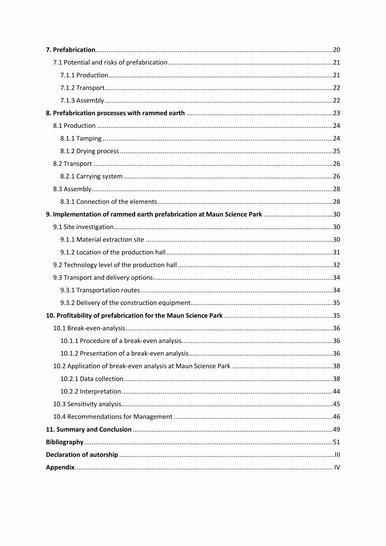
The city of Maun is in the north of the country at the outlets of the Okavango Delta. Maun has
60,263 inhabitants and is the fourth largest city in Botswana.7 The building site for the Maun
Science Park is centrally located only a few 100 metres south of the international airport. The
plot is 2.5km² in size and is located on the banks of the Thamalakane River. Maun has
developed rapidly in recent years and in addition to the traditional cattle farming there are
now hotels, shopping centres and car rental agencies.8
3 (cf. Koulolias, 2020) 4 (cf. Botswana- allgemeine Informationen, 2021) 5 (cf. United Nations Development Programme, 2019) 6 (cf. Breda, 2020) 7 (cf. city population, 2020) 8 (cf. Bühler, The Vision, 2020)
4
Figure 1: Maun Science Park property9
2.3 Project goals
Vasilis Koulolias describes the MSP as a prototypical habitat for overcoming the challenges of
the future. The construction of the project is intended to create a test habitat that can be used
to study and understand how the interconnection of people, machines and applications can
create a ubiquitous system and how this can improve daily life.10
This top objective can be broken down into five sub-objectives for easier tracking and
understanding.
1. Objective
Made in Botswana: The project meets the requirements of the regional stakeholders and
focuses primarily on human demands, as well as local and sustainable resources and services.
2. Objective
State of the art: Construction of a sophisticated infrastructure that enables intelligent systems
to make the best use of local conditions, and optimally integrate into the ecological system by
using state of the art technology.
9 (Bühler, The Vision, 2020) 10 (cf. Koulolias, 2020)

5
3. Objective
Study and provide: The project offers the opportunity to better understand and be aware of
the connection to nature. It supports the transfer of knowledge and ensures the dissemination
of proven technologies to other housing projects around the world.
4. Objective
Best practice for innovation regulation: Creating a recipe for approvals for innovation in
construction. The project serves as an example of how a government deals with the
implementation of new technologies in construction.
5. Objective
Create jobs and prosperity: Develop a smart living business incubator that acts like a machine,
pushing forward developments such as integrated smart infrastructure and community
building. The focus of the incubator is initially on regional areas, expanding from sub-Saharan
Africa until the focus of the machine is on the whole world.11
3. Rammed earth - a sustainable building material
Rammed earth is a very old building material. The technique was first mentioned in 814 BC.12
Over time, the building material fell into oblivion and has only been experiencing more
interest and a revival in recent years. On the one hand, this is probably due to the strong
architectural appearance of the heavy, monolithic walls,13 and on the other hand, to the
enormous ecological potential of the building material, which is very important in terms of the
global challenge of countering climate change. One goal of the Maun Science Park is to keep
the emission of pollutants as low as possible, both during construction and in later use.
Rammed earth has the potential to help the Maun Science Park achieve this goal and is worthy
of closer consideration for the creation of the Maun Science Park.
11 (cf. Bühler, Project Goals, 2020) 12 (cf. Boltshauser, 2019, p. 15) 13 (cf. Röhlen & Ziegert, 2020, p. 210)
6
3.1 Basic principle of the construction process
Since the discovery of rammed earth for building walls, the basic principle of its use has
remained the same. Earth-moist loam is mixed with gravel or straw and then filled in layers
into a wall formwork. Each layer is then compacted by applying pressure before the next layer
of the clay-gravel mixture is placed. This process is repeated until the desired height of the
wall is reached. The subsequent drying of the building material creates a stable wall. When
using the building material outdoors, it is nevertheless important to take appropriate
measures to ensure that it is not directly exposed to the weather. Compared to bricks or tiles,
rammed earth is not burnt and is therefore more susceptible to erosion.
In the past, the building material was compacted by tamping with bare feet. Nowadays,
pneumatic or electric tampers are used for this purpose.14 Depending on the grain size
distribution, rammed earth layers of a height between 10cm and 15cm can be placed in the
formwork. A high pouring height should be avoided as the material can segregate. The placed
layers are then reduced to 2/3 of the initial height by compacting. If no further compaction is
visible after repeated tamping, the next layer can be placed. The same formwork can be used
as in concrete construction. It is important that the formwork elements withstand a formwork
pressure of at least 60kn/m², as the pressure created during compaction is often
underestimated. The formwork must be free of oils and cement residues, as even the smallest
remnants can cause discolouration. To be able to remove the formwork more easily after
tamping, vegetable oil is often applied to the formwork skin. After stripping the formwork,
any defects must be repaired directly. It should also be noted that the stripped walls are not
immediately loadable due to the slow drying time, which must be planned for in the further
construction process.15
3.2 Ecological approach to the building material
The energy consumption of a building material and thus its influence on the climate depends
mainly on two components. On the one hand, energy is needed to operate a finished building
over its life cycle, and on the other hand to construct a building. The energy used to operate
a building depends mainly on the compactness of the building, the amount of heat loss due to
14 (cf. Grimm, 2019) 15 (cf. Röhlen & Ziegert, 2020, pp. 216-220)
7
the type of insulation and also the orientation of the building, as well as the number and size
of the window openings. Due to increasingly rigorous energy regulations, measures to save
energy by reducing the heating requirements for the operation of the building have been
practically exhausted. Against this background, the reduction of the energy required to
construct a building is receiving more attention. The energy used to construct a building is also
called grey energy. The grey energy describes the complete effort that is spent to produce the
building component, including the extraction of the building material, the transport to the
production site, the production itself and the final installation. Compared to other building
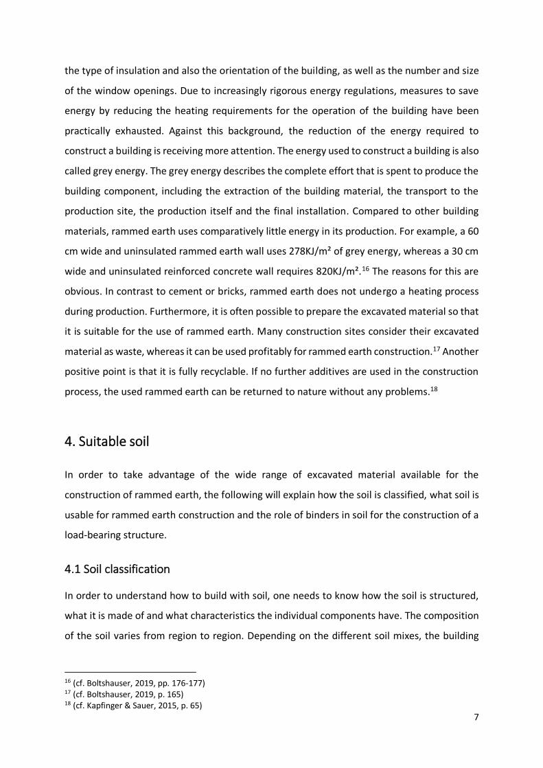
materials, rammed earth uses comparatively little energy in its production. For example, a 60
cm wide and uninsulated rammed earth wall uses 278KJ/m² of grey energy, whereas a 30 cm
wide and uninsulated reinforced concrete wall requires 820KJ/m².16 The reasons for this are
obvious. In contrast to cement or bricks, rammed earth does not undergo a heating process
during production. Furthermore, it is often possible to prepare the excavated material so that
it is suitable for the use of rammed earth. Many construction sites consider their excavated
material as waste, whereas it can be used profitably for rammed earth construction.17 Another
positive point is that it is fully recyclable. If no further additives are used in the construction
process, the used rammed earth can be returned to nature without any problems.18
4. Suitable soil
In order to take advantage of the wide range of excavated material available for the
construction of rammed earth, the following will explain how the soil is classified, what soil is
usable for rammed earth construction and the role of binders in soil for the construction of a
load-bearing structure.
4.1 Soil classification
In order to understand how to build with soil, one needs to know how the soil is structured,
what it is made of and what characteristics the individual components have. The composition
of the soil varies from region to region. Depending on the different soil mixes, the building
16 (cf. Boltshauser, 2019, pp. 176-177) 17 (cf. Boltshauser, 2019, p. 165) 18 (cf. Kapfinger & Sauer, 2015, p. 65)

8
material has different characteristics, which makes it difficult to standardize earthen building.
It is essential to carry out a thorough soil investigation before starting construction to ensure
the load-bearing capacity of the building.
The soil structure is composed as follows. The top layer is the humus layer. It is up to 50cm
thick and consists mainly of dead organic matter. The layer underneath is called the subsoil. It
contains mainly inorganic material mixtures of clay, gravel and sand. Depending on the region,
the subsoil can be up to several metres thick. The lowest layer consists of unweathered rock,
also known as bedrock.19
For building with soil, the composition of the subsoil is crucial. The soil is classified according
to the grain size of the substances it contains.
The largest grains with a size between 2mm and 63mm are called gravel. Gravel is the term
for stones that are crushed by weathering or by machine use in quarries. They differ in shape,
structure and strength. This is because each pebble has the characteristics of the parent rock
from which it broke off.20
Grains that are between 2 mm and 0.063 mm in size are counted as sands. Sand is eroded
quartz rock. The grains can have any shape.20 Due to large cavities in sandy soils, water can
percolate very well, and the soil is poor in minerals.21 Pure sand is friable and does not hold
together. For sand to hold together and have good soil density, it must be mixed with a binder,
such as cement or clay.
Even smaller particles are assigned to the group of silts.
They have a grain size of 0.063mm to 0.002mm. The microscopic components of the silt
contribute to increasing the density in the soil by being deposited in cavities. However, too
much silt in the soil can also have a negative effect on the load-bearing capacity. On one hand,
because grains are relatively round and cannot wedge well, and on the other hand, because
the surface area increases by the addition of silt and thus more binder is needed to hold the
soil together.22
The smallest grains are called clays. Clays differ from other soil types mainly in their shape.
Seen under a microscope, clay looks like small leaves. These leaflets are held together by
cohesion. When clay is wet, the water forms capillary bridges between the leaflets, which
19 (cf. Boltshauser, 2019, p. 167) 20 (cf. Easton, 1996, p. 90) 21 (cf. Bayrisches Landesamt für Umwelt, 2020) 22 (cf. Easton, 1996, p. 89f.)

9
makes them stick together. When dry, the clay hardens and loses its excellent plasticity
properties due to the evaporation of the pore water. The clay reaches its greatest strength
when the excess water has evaporated.23 The evaporation of the pore water causes the clay
to shrink. With larger pieces of clay, this inevitably leads to the formation of cracks, which is
why it is impossible to build a large rammed earth element from pure clay. Because of these
properties, clay is the binder of earthen building. It ensures that the grain structure is held
together and that a monolithic unit can be formed. Clay in earthen construction is comparable
to the use of cement in concrete construction.23
4.2 Soil composition for rammed earth construction
A good approach to obtain information about the correct composition of the soil is to examine
rammed earth walls that have already been built and have been in place for a century or more.
The oldest rammed earth elements were formed from a soil composition of 70% sand and
30% clay. However, it is very unlikely to find such a soil composition on site or near the vicinity.
Over time, other compositions of coarse-grained proportions such as a gravely-clay mixture
have been also shown to work as a proper building material. The composition varies
depending on the local conditions and one must be prepared to improve the soil quality. If a
soil does not have the right composition and is too clayey on the one hand, it can be made
usable by adding some sand and gravel. If, on the other hand, there is too little clay in the soil,
one can mix it with another soil that is too clayey or add cement and make it usable for little
money.24 It is also important that the grains are not too round so that they can interlock and
ensure load transfer. A maximum grain size of 16mm is usually used for walls.25 One needs to
know that gravel and sand form the structure of the wall and the clay in combination with
water ensures that the grains hold together. That is why clay is also called binder in earthen
construction.
4.3 Binder
Binders are also known as stabilisers. They take on the task of preventing the volume change
that occurs through the absorption and release of water in a building material.26 Besides clay,
23 (cf. Boltshauser, 2019, p. 170) 24 (cf. Easton, 1996, p. 91f.) 25 (cf. Röhlen & Ziegert, 2020, p. 210) 26 (cf. Easton, 1996, p. 98)
10
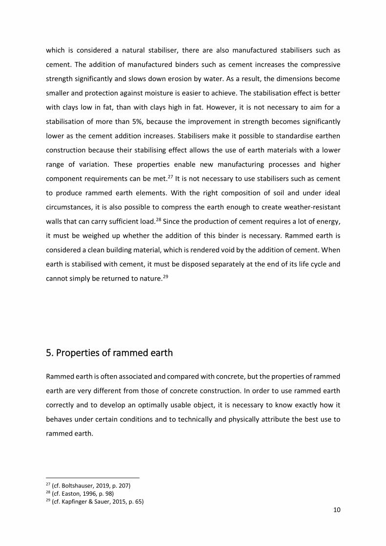
which is considered a natural stabiliser, there are also manufactured stabilisers such as
cement. The addition of manufactured binders such as cement increases the compressive
strength significantly and slows down erosion by water. As a result, the dimensions become
smaller and protection against moisture is easier to achieve. The stabilisation effect is better
with clays low in fat, than with clays high in fat. However, it is not necessary to aim for a
stabilisation of more than 5%, because the improvement in strength becomes significantly
lower as the cement addition increases. Stabilisers make it possible to standardise earthen
construction because their stabilising effect allows the use of earth materials with a lower
range of variation. These properties enable new manufacturing processes and higher
component requirements can be met.27 It is not necessary to use stabilisers such as cement
to produce rammed earth elements. With the right composition of soil and under ideal
circumstances, it is also possible to compress the earth enough to create weather-resistant
walls that can carry sufficient load.28 Since the production of cement requires a lot of energy,
it must be weighed up whether the addition of this binder is necessary. Rammed earth is
considered a clean building material, which is rendered void by the addition of cement. When
earth is stabilised with cement, it must be disposed separately at the end of its life cycle and
cannot simply be returned to nature.29
5. Properties of rammed earth
Rammed earth is often associated and compared with concrete, but the properties of rammed
earth are very different from those of concrete construction. In order to use rammed earth
correctly and to develop an optimally usable object, it is necessary to know exactly how it
behaves under certain conditions and to technically and physically attribute the best use to
rammed earth.
27 (cf. Boltshauser, 2019, p. 207) 28 (cf. Easton, 1996, p. 98) 29 (cf. Kapfinger & Sauer, 2015, p. 65)
11
5.1 Structural properties
5.1.1 Bulk density
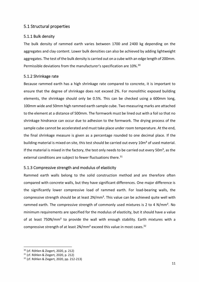
The bulk density of rammed earth varies between 1700 and 2400 kg depending on the
aggregates and clay content. Lower bulk densities can also be achieved by adding lightweight
aggregates. The test of the bulk density is carried out on a cube with an edge length of 200mm.
Permissible deviations from the manufacturer's specification are 10%.30
5.1.2 Shrinkage rate
Because rammed earth has a high shrinkage rate compared to concrete, it is important to
ensure that the degree of shrinkage does not exceed 2%. For monolithic exposed building
elements, the shrinkage should only be 0.5%. This can be checked using a 600mm long,
100mm wide and 50mm high rammed earth sample cube. Two measuring marks are attached
to the element at a distance of 500mm. The formwork must be lined out with a foil so that no
shrinkage hindrance can occur due to adhesion to the formwork. The drying process of the
sample cube cannot be accelerated and must take place under room temperature. At the end,
the final shrinkage measure is given as a percentage rounded to one decimal place. If the
building material is mixed on site, this test should be carried out every 10m³ of used material.
If the material is mixed in the factory, the test only needs to be carried out every 50m³, as the
external conditions are subject to fewer fluctuations there.31
5.1.3 Compressive strength and modulus of elasticity
Rammed earth walls belong to the solid construction method and are therefore often
compared with concrete walls, but they have significant differences. One major difference is
the significantly lower compressive load of rammed earth. For load-bearing walls, the
compressive strength should be at least 2N/mm². This value can be achieved quite well with
rammed earth. The compressive strength of commonly used mixtures is 2 to 4 N/mm². No
minimum requirements are specified for the modulus of elasticity, but it should have a value
of at least 750N/mm² to provide the wall with enough stability. Earth mixtures with a
compressive strength of at least 2N/mm² exceed this value in most cases.32
30 (cf. Röhlen & Ziegert, 2020, p. 212) 31 (cf. Röhlen & Ziegert, 2020, p. 212) 32 (cf. Röhlen & Ziegert, 2020, pp. 212-213)
12
To better visualise these values and according to Paul Marais, an experienced rammed earth
builder, it can be said that a rammed earth wall must have a thickness of around 1/10 of the
building height in order to be sufficiently load-bearing, including securities.33 This means that
for a single storey building with a height of 3.50m, a 35 cm thick rammed earth wall provides
enough stability. For a 10m high building, the wall would have to be 1.00m thick. These are
significantly larger dimensions than with concrete walls and this must be considered in the
planning.
5.2 Physical properties
5.2.1 Thermal insulation
Clay and wood combine two very different physical properties and stand out from the
regularity. The regularity states that heavy building materials store heat better than light
building materials but insulate worse. Despite their high mass, clay and wood have a
comparatively high thermal insulation value.34
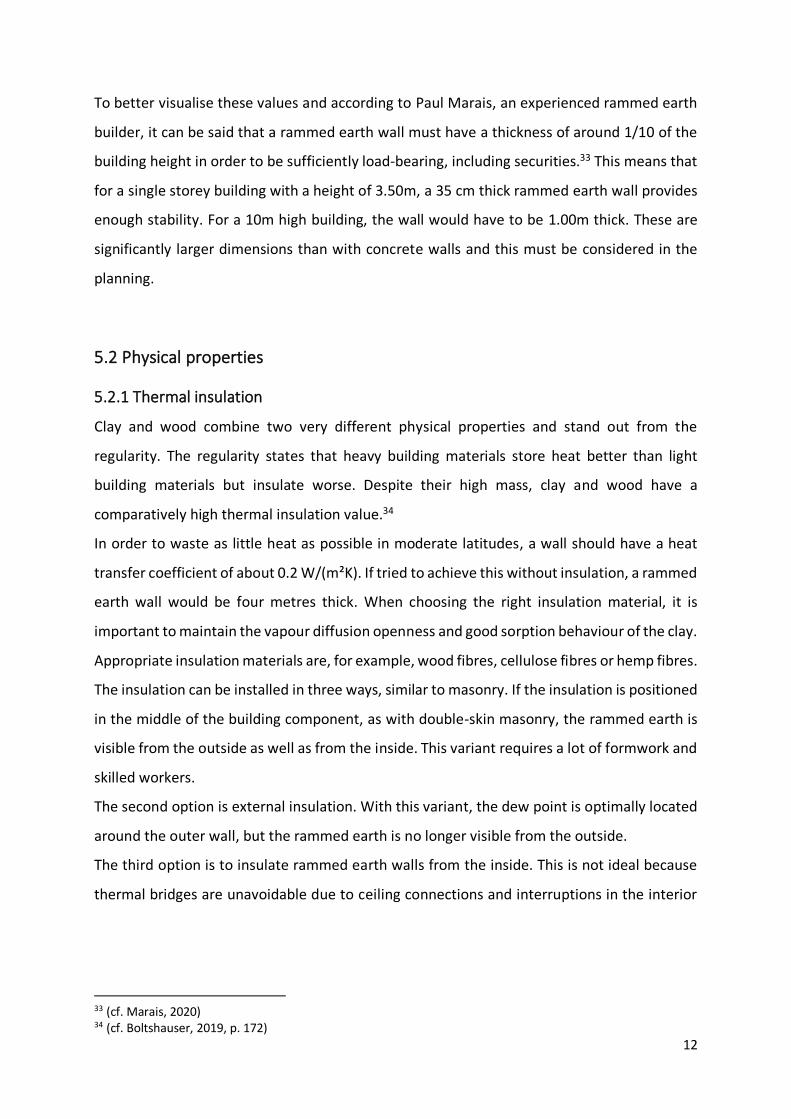
In order to waste as little heat as possible in moderate latitudes, a wall should have a heat
transfer coefficient of about 0.2 W/(m²K). If tried to achieve this without insulation, a rammed
earth wall would be four metres thick. When choosing the right insulation material, it is
important to maintain the vapour diffusion openness and good sorption behaviour of the clay.
Appropriate insulation materials are, for example, wood fibres, cellulose fibres or hemp fibres.
The insulation can be installed in three ways, similar to masonry. If the insulation is positioned
in the middle of the building component, as with double-skin masonry, the rammed earth is
visible from the outside as well as from the inside. This variant requires a lot of formwork and
skilled workers.
The second option is external insulation. With this variant, the dew point is optimally located
around the outer wall, but the rammed earth is no longer visible from the outside.
The third option is to insulate rammed earth walls from the inside. This is not ideal because
thermal bridges are unavoidable due to ceiling connections and interruptions in the interior
33 (cf. Marais, 2020) 34 (cf. Boltshauser, 2019, p. 172)

13
wall. It is important that no moisture is deposited on the inside surface. This is achieved by
capillary-active insulation such as wood fibre.35
As already mentioned, the installation of insulation makes sense in cold regions. However,
there are also regions where the installation of insulation is not beneficial, and this is due to
the good heat storage capacity of rammed earth.
The city of Maun is a good example to explain this. Temperatures in Maun are very high during
the day, between 25 and 35 degrees Celsius, and comparatively low at night, at around 5 to
18 degrees Celsius. During the day, the rammed earth wall takes on the heat of the outside
temperature. At night, it releases it back into the environment. This means that at night the
interior rooms are heated by the rammed earth wall and during the day the interior rooms
are cooled by the rammed earth wall. Omitting the insulation makes sense if the temperature
differences between day and night are comparatively large and the average temperature over
a longer period can be considered comfortable.36
Figure 2: climate diagram Maun 37
5.2.2 Humidity regulation
A great advantage of clay is that it compensates different vapour pressures. To be able to use
this property, an exchange of moisture between inside and outside must remain possible and
no sealing materials shall be installed. Moisture accumulating in the interior can be released
to the outside without additional ventilation and no moisture peaks occur. In buildings made
of loam, the humidity inside is 50%. People find a humidity of 30% to 60% comfortable. If the
humidity is too high, structural damage can occur and the comfort level drops. Loam is even
35 (cf. Boltshauser, 2019, pp. 173-174) 36 (cf. Ciancio, 2015) 37 (Average Day And Night Temperature In Maun In Celsius, 2019)

14
able to filter pollutants out of the air through its small-grained components and it achieves an
optimal level of comfort from a medical point of view. The air in buildings made of clay is fresh
and free of unpleasant smells.38
5.2.3 Fire protection
According to previous experience, rammed earth walls are sufficiently resistant to fire even at
a low thickness and can therefore be classified in fire resistance class F90 according to the
Lehmbauregeln at a thickness of 24 cm and a density of 1700 kg/m³.39
6. Technical challenges in rammed earth construction
Since the art of building with earth has fallen into oblivion and has only been gaining
momentum again in recent years, there are gaps in knowledge that need to be addressed.
Mainly in the technical field, it is difficult to make rammed earth competitive with concrete,
wood and steel due to low spans and low resistance to water.
The following section presents ways in which these challenges can be overcome with creativity
and technology, and how rammed earth construction can be made more suitable for everyday
use.
6.1 Requirements for weather protection
Rammed earth walls are surprisingly resistant to erosion by water and wind. The reason for
this is that the material is compacted by tamping as the wall is being built. Nevertheless, rain
wears away the wall over the years if it is unprotected. But even protected walls change
gradually over time. The surface of the wall softens, and the soft clay is washed out. The
coarser-grained stones emerge visibly, and the wall changes its colour and structure.40
Weather resistance by adding cement or by applying an exterior render is possible, but not
relevant, as a rammed earth wall is usually constructed as an exposed wall and the addition
of cement does not correspond to the ideas of modern climate-neutral building.41
Shown below are several other ways to slow down the process of weathering.
38 (cf. Boltshauser, 2019, pp. 174-176) 39 (cf. Röhlen & Ziegert, 2020, p. 233) 40 (cf. Kapfinger & Sauer, 2015, p. 65) 41 (cf. Röhlen & Ziegert, 2020, p. 222)

15
6.1.1 Overhanging roofs
Roof overhangs are the best way to protect the upper part of a building from driving rain. The
larger these are, the more surface area of the building is protected. In addition, they protect
against the heat of the sun in summer and provide shade. For constructions with flat roofs or
even free-standing walls, it is advisable to cover the surface with sheet metals or other water-
repellent materials.42
6.1.2 Water repellent base
The lower part of the building must be protected as carefully as the roof. The plinth should be
at least 30 cm high around the outer walls and it should be made of solid, water-repellent
materials to protect against splash water. A water-repellent solid layer of screed concrete is
placed on top of to the horizontal barrier in order to protect it from accumulating rainwater
and damage during construction.43
6.1.3 Erosion brake
To protect not only the base and the roof from erosion, but also the wall, so-called erosion
brakes can be installed. When rainwater runs along a rammed earth wall, it washes out
material. The faster the rainwater runs down the wall, the more material is washed out.
Erosion brakes slow down this process and help to control the waterflow. They are horizontally
installed layers of protruding stones or burnt bricks. Alternatively, layers of trass lime mortar
can be integrated flush into the wall. The trass lime mortar layers will protrude from the wall
over time as they erode more slowly, and therefore slow down the rainwater runoff.44 For
prefabrication in the factory, the erosion brakes made of trass lime mortar are much more
suitable, as they are integrated flush into the wall and do not protrude like the erosion brakes
made of stones or fired bricks. This simplifies the transport of the elements and the
manufacturing process, because the formwork effort is reduced, and the production is more
standardised.45 In dry regions, one can consider leaving out the erosion brakes, as the wall
becomes increasingly hardened over time.
42 (cf. Kapfinger & Sauer, 2015, p. 65) 43 (cf. Röhlen & Ziegert, 2020, p. 222) 44 (cf. Kapfinger & Sauer, 2015, p. 70) 45 (cf. Kapfinger & Sauer, 2015, p. 73)

16
Figure 3: Erosion brakes made of trass lime with ongoing erosion46
6.2 Requirements for load-bearing and structural elements
Due to the static properties of earth, a unique form language has developed in earthen
construction. Similar to other solid buildings, the walls are very thick and instead of large
openings, these are narrow and sparsely set. However, open and light-flooded buildings are
inviting and convey comfort. To achieve openness and a flood of light despite the material
properties, extensive design and construction planning of the openings in rammed earth
buildings is essential. Every opening creates turbulence of calculated erosion and weakens the
supporting structure. Lintels create drip edges and the corners of the openings are exposed
to the weather on two sides. This material erosion must be slowed down by additional detail
work.47
6.2.1 Lintel
In traditional rammed earth construction, lintels are usually made of wooden beams. These
are visibly rammed into the masonry and take over the spanning of the opening. As soon as
larger openings must be spanned, lintel elements made of trass lime mortar or even reinforced
concrete are cast into the wall and take over the load transfer.
46 (Kapfinger & Sauer, 2015, p. 73) 47 (cf. Kapfinger & Sauer, 2015, p. 85)

17
There are several ways to integrate lintels into the rammed earth wall. The most suitable
variant is selected according to the wishes of the client and the constructional possibilities.48
1. Tamped down reinforcement
To span small openings, a reinforcement can be rammed in. This reinforcement is
tamped into a mixture of trass lime and clay in the form of an arch. In this way, this
lintel element transfers the tensile and compressive forces as a wedge structure. The
problem is that the larger the opening, the higher the arch must be.49
Figure 4: Lintel with rammed reinforcement 50
2. Avoiding the lintel
Another way to avoid lintel details is to omit them entirely. In this method, the walls
consist of individual slabs and the openings extend from the base to the ceiling above
or, if the building is single-storey, from the base to the roof. The roof or ceiling takes
on the role of the lintel. The integrated interruptions in the wall give the building a very
open appearance, which greatly simplifies the prefabrication of the wall slabs.51
Figure 5: Avoided lintel 52
48 (cf. Kapfinger & Sauer, 2015, pp. 85-90) 49 (cf. Kapfinger & Sauer, 2015, p. 90) 50 (Kapfinger & Sauer, 2015, p. 90) 51 (cf. Kapfinger & Sauer, 2015, p. 90) 52 (Kapfinger & Sauer, 2015, p. 90)

18
3. Lintel from other materials
If the spanning is too large, and ramming a wooden beam is not strong enough to carry
the load, materials such as steel or reinforced concrete are used. Lintels of this method
are often invisibly integrated into the wall and the façade is made entirely of loam. To
achieve this, the lintel element is not installed flush with the outer wall. A layer of loam
is placed in front of the lintel element. This loam layer is not load-bearing but is
supported by the lintel element and allows a homogeneous appearance despite large
openings.53
Figure 6: Lintel from another material 54
4. Stacking of prefabricated elements
The prefabrication of rammed earth elements offers advantages in the formation of
the lintel, among many other benefits. One possible variant is to stack wall elements
with built-in reinforced concrete lintels on top of the load-bearing wall slabs and
thereby span the openings in the wall. The bottom layer of the wall elements with
reinforced concrete lintel forms a steel plate that recedes at the bearings and is
therefore no longer visible in the wall. The bearings of the wall elements are
strengthened with reinforced trass lime mortar and ensure sufficient load transfer.55
Figure 7: Stacking prefabricated elements 56
53 (cf. Kapfinger & Sauer, 2015, p. 91) 54 (Kapfinger & Sauer, 2015, p. 90) 55 (cf. Kapfinger & Sauer, 2015, pp. 98-101) 56 (Kapfinger & Sauer, 2015, p. 91)

19
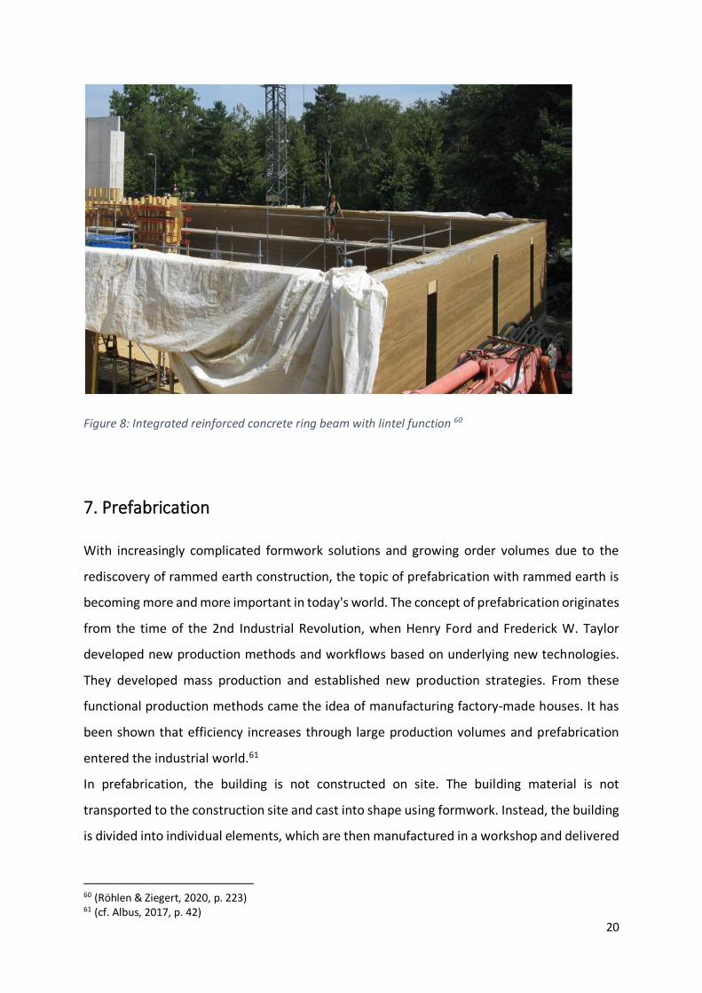
6.2.2 Ring beam and ring anchor
Ring anchors or ring beams are used to stabilise wall crowns and bearing surfaces of floor
slabs. They create additional stability in the supporting structure and compensate for the
missing discs and ring tensile functions of the reinforced concrete slab.57 The ring beam also
serves as an interface between the earthwork builder and the roofer and is used as a fixed
mounting option for attaching the roof above.58
For the installation of the ring beam, a recess is provided in the top layers of the rammed earth
wall in the middle of the cross-section. The reinforcement of the ring beam can then be placed
in this recess and can be poured with concrete. Normally the ring beam is not visible because
the cross-section of a rammed earth wall is large enough to be able to place the ring beam in
the middle of the wall and cover it with rammed earth.
Ring beams can also be made of wood. Wooden ring beams must be rammed into the wall
with tie rods and head plates because of the shear forces that occur. Wood can also swell
strongly due to the moist rammed earth during installation and can therefore lead to cracking
of the coating.59
Depending on the wood resources in the region and in order to avoid CO2 emissions during
concrete production, the use of wooden ring beams can be considered despite the more
complex installation method.
57 (cf. Röhlen & Ziegert, 2020, p. 223) 58 (cf. Kapfinger & Sauer, 2015, p. 80) 59 (cf. Röhlen & Ziegert, 2020, p. 224)
20
Figure 8: Integrated reinforced concrete ring beam with lintel function 60
7. Prefabrication
With increasingly complicated formwork solutions and growing order volumes due to the
rediscovery of rammed earth construction, the topic of prefabrication with rammed earth is
becoming more and more important in today's world. The concept of prefabrication originates
from the time of the 2nd Industrial Revolution, when Henry Ford and Frederick W. Taylor
developed new production methods and workflows based on underlying new technologies.
They developed mass production and established new production strategies. From these
functional production methods came the idea of manufacturing factory-made houses. It has
been shown that efficiency increases through large production volumes and prefabrication
entered the industrial world.61
In prefabrication, the building is not constructed on site. The building material is not
transported to the construction site and cast into shape using formwork. Instead, the building
is divided into individual elements, which are then manufactured in a workshop and delivered
60 (Röhlen & Ziegert, 2020, p. 223) 61 (cf. Albus, 2017, p. 42)
21
to the construction site ready for installation. Instead of erecting a wall in situ to the total floor
height, the prefabricated elements are stacked on top of each other until they reach the
specified height.62 In prefabrication, production and assembly are therefore two separate
processes. Depending on the distance between the construction site and the workshop or the
possibility of positioning a temporary workshop near the site, transport and logistics play an
increasing role in the construction process. Prefabrication has established itself due to several
economic advantages, which are listed below. However, they must be viewed with caution, as
the separation of the construction process into production and assembly also reveals
disadvantages in other areas.
7.1 Potential and risks of prefabrication
In the prefabrication of reinforced concrete, timber and steel elements, a great deal of
experience is already available, which makes it easy to identify the advantages and
disadvantages of the various forms of prefabrication. The experience values in rammed earth
prefabrication are still very small and one must acquire a wealth of experience through trial
and error in order to be able to weigh up when prefabrication makes sense and when it does
not. Logically, since rammed earth also belongs to the massive construction method and can
be compared well with concrete, the following advantages and disadvantages are based on
the experience of reinforced concrete prefabrication and can certainly be transferred to the
prefabrication of rammed earth. The advantages and disadvantages are to be considered in
general and cannot apply directly to every type of construction site.
7.1.1 Production
One of the biggest advantages of prefabrication is the availability of a controlled and
consistent working environment. By producing in the factory hall, the elements to be
manufactured are always protected from the outside weather. As a result, work can be carried
out in any weather and there are no delays.63
Furthermore, prefabrication promises better dimensional accuracy than on-site production.64
This is mainly due to the subdivision of entire wall panels into individual elements. The
formwork of the elements can be assembled and filled on the ground. There is no need for
62 (cf. Kapfinger & Sauer, 2015, p. 78) 63 (cf. Knaack, Chung-Klatte, & Hasselbach, 2012, p. 46) 64 (cf. Knaack, Chung-Klatte, & Hasselbach, 2012, p. 46)

22
complicated climbing formwork that grows upwards with the building and must be secured
against slipping. Especially in rammed earth construction, the formwork must withstand high
pressure and be well secured due to the thick walls and the heavy compaction of the material
by pneumatic rammers.65
To ensure that the building materials have sufficiently good properties, such as high
compressive strength and low shrinkage, quality tests are carried out repeatedly. It is easier
to carry out such tests in prefabrication. In the case of rammed earth, according to the
Lehmbauregeln, for prefabrication a test must be carried out every 50m³, whereas for on-site
production a test must already be carried out every 10m³.66
7.1.2 Transport
A clear disadvantage is higher costs of transport. Because of the geographical separation of
the construction process into production and assembly, the finished element must be
transported to the installation site between the two steps. This step is to be evaluated
differently in the planning depending on the location of the workshop and the development
stage of the infrastructure on site. In addition, the dimensions of the finished elements are
mainly limited by transport. A truck can only transport a certain weight. This weight depends
on the material properties and on the securing of the goods to be transported. In the case of
rammed earth, the greatest restriction on transport volume is the high weight of the finished
rammed earth elements themselves. Due to the relatively low compressive strength of the
material, the cross-section must be very large to be able to carry sufficient load.
The payload of the crane required to move the panels can also limit the size of the panels. In
short, transport is the limiting factor in prefabrication and must always be considered very
carefully in planning.
7.1.3 Assembly
The assembly of the finished parts then takes place on site. The elements are lifted by a crane
to their installation location and then seamlessly joined to the already installed parts with
mortar and or a tongue and groove plug-in system. The installation time on site is significantly
accelerated by prefabrication. This makes prefabrication particularly attractive for very
65 (cf. Röhlen & Ziegert, 2020, pp. 216-217) 66 (cf. Röhlen & Ziegert, 2020, p. 213)
23
narrow construction sites where it is very expensive to build because of lack of space.67 Due
to the outsourced production, combined with a well-planned transport management, large
storage areas on the construction site can be dispensed with and no elaborate scaffolding
constructions have to be erected. In addition, the elements do not have to dry out afterwards
and the following crafts can carry out their work directly.68
But prefabrication can also be used to advantage on building sites with a large amount of
space, such as the construction of a new residential district in the suburbs, where houses need
to be built in large numbers and in a short time. Through prefabrication and the resulting
standardisation of the individual elements, fixed prices for the elements and detailed solutions
develop over time.69 Calculations can be made more accurately and the risk of encountering
problems during the construction of the shell is minimised.
8. Prefabrication processes with rammed earth
To be able to exploit the advantages of prefabrication in rammed earth construction as well,
companies such as Lehm Ton Erde Baukunst GmbH spend a lot of energy on making the
processes for prefabricating rammed earth ready for the market. The first prefabricated
rammed earth element was produced in 1997 by the company to avoid bad weather and tight
schedules. Since then, prefabricated construction has continued to develop, and entire
buildings have been constructed in prefabrication. While the ratio of production to assembly
was initially 6:1, by 2015 it was already 3:1. This is due to improved processes and an
accompanying acceleration of prefabrication.70 In order to be able to use the potential of
prefabrication correctly and to understand which adjusting screws are decisive in
prefabrication, the working steps of prefabrication are explained below.
67 (cf. Knaack, Chung-Klatte, & Hasselbach, 2012, p. 46) 68 (cf. Kapfinger & Sauer, 2015, p. 118) 69 (cf. Knaack, Chung-Klatte, & Hasselbach, 2012, p. 46) 70 (cf. Kapfinger & Sauer, 2015, pp. 118-119)
24
8.1 Production
8.1.1 Tamping
The tamping of the material is very different from the on-site construction method. Instead of
gradually ramming the material into the formwork and creating a room-high wall, the wall is
divided into small elements during prefabrication, which are then assembled on site to create
a wall. To reduce the amount of formwork required, a so-called endless wall is produced in
the workshop. For this purpose, a formwork is erected over any desired length and height and
then the material is tamped in. After removing the formwork, the endless wall is cut into small,
transportable wall elements.71 The wall elements are numbered in the factory and then re-
installed on the construction site in this order. Details such as lintels, necessary ring beams or
empty pipes for installations are stamped directly into the endless wall and do not have to be
produced on site.72
The tamping of the material is done according to a known pattern. The material is filled into
the formwork layer by layer and compacted by pneumatic compactors every 15cm.
Prefabrication has the advantage that loose material does not have to overcome any height
to reach the installation site and thus no fall protection is necessary. Another advantage of
the endless wall is that several teams of workers can work simultaneously. Compared to in-
situ production, the workers are not restricted by the given geometry of the building and have
much more space. This speed up the work process. A characteristic of prefabrication is the
elimination of physical labour. In rammed earth production, compacting and placing the
material in the formwork is the most strenuous activity. For this reason, the company Lehm
Ton Erde Baukunst GmbH has developed a machine that can be attached to the endless wall
and takes over the compaction work.73 The machine is particularly advantageous for long
formwork runs and large construction sites and enables the construction of narrower walls,
as no worker has to climb into the formwork for compaction.74 Nevertheless, a lot of manual
work remains, especially for wall elements with details.
71 (cf. Kapfinger & Sauer, 2015, p. 78) 72 (cf. Kapfinger & Sauer, 2015, p. 98) 73 (cf. Kapfinger & Sauer, 2015, p. 119) 74 (cf. Kapfinger & Sauer, 2015, p. 120)

25
Figure 9: Production of an endless wall75
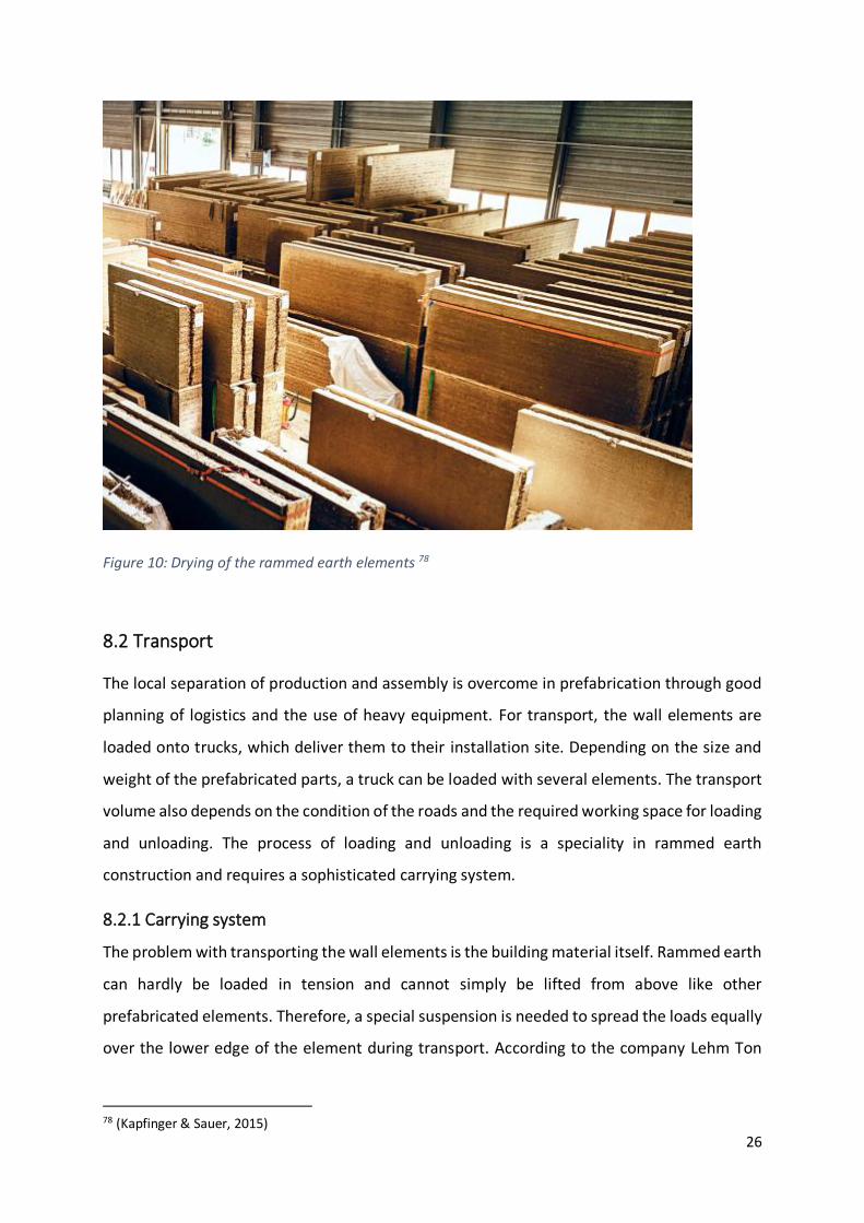
8.1.2 Drying process
After the elements have been stripped and sawn to size, the drying process takes place. For
this purpose, the wall elements are stored in another part of the workshop until they have
reached the desired degree of humidity. This process can take several weeks,76 depending on
the surrounding conditions. By drying the elements in the hall, the following works can follow
immediately after the elements have been installed on the construction site, which
significantly shortens the construction time.77 When storing the elements, it is necessary to
pay attention to the sequence of the construction process, as otherwise unnecessary moving
of the wall elements is necessary.
75 Figure based on (cf. Kapfinger & Sauer, 2015, p. 119) 76 (cf. Boltshauser, 2019, p. 205) 77 (cf. Kapfinger & Sauer, 2015, p. 118)
26
Figure 10: Drying of the rammed earth elements 78
8.2 Transport
The local separation of production and assembly is overcome in prefabrication through good
planning of logistics and the use of heavy equipment. For transport, the wall elements are
loaded onto trucks, which deliver them to their installation site. Depending on the size and
weight of the prefabricated parts, a truck can be loaded with several elements. The transport
volume also depends on the condition of the roads and the required working space for loading
and unloading. The process of loading and unloading is a speciality in rammed earth
construction and requires a sophisticated carrying system.
8.2.1 Carrying system
The problem with transporting the wall elements is the building material itself. Rammed earth
can hardly be loaded in tension and cannot simply be lifted from above like other
prefabricated elements. Therefore, a special suspension is needed to spread the loads equally
over the lower edge of the element during transport. According to the company Lehm Ton
78 (Kapfinger & Sauer, 2015)
27
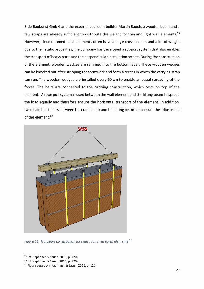
Erde Baukunst GmbH and the experienced loam builder Martin Rauch, a wooden beam and a
few straps are already sufficient to distribute the weight for thin and light wall elements.79
However, since rammed earth elements often have a large cross-section and a lot of weight
due to their static properties, the company has developed a support system that also enables
the transport of heavy parts and the perpendicular installation on site. During the construction
of the element, wooden wedges are rammed into the bottom layer. These wooden wedges
can be knocked out after stripping the formwork and form a recess in which the carrying strap
can run. The wooden wedges are installed every 60 cm to enable an equal spreading of the
forces. The belts are connected to the carrying construction, which rests on top of the
element. A rope pull system is used between the wall element and the lifting beam to spread
the load equally and therefore ensure the horizontal transport of the element. In addition,
two chain tensioners between the crane block and the lifting beam also ensure the adjustment
of the element.80
Figure 11: Transport construction for heavy rammed earth elements 81
79 (cf. Kapfinger & Sauer, 2015, p. 120) 80 (cf. Kapfinger & Sauer, 2015, p. 120) 81 Figure based on (Kapfinger & Sauer, 2015, p. 120)

28
8.3 Assembly
By dividing a wall into individual elements, several things must be considered during the
following assembly of the prefabricated parts. To create a monolithic wall from the individual
elements, great importance must be attached to well executed connections. These
connections must meet the structural and physical requirements and should no longer be
visible at the end of the construction process.
8.3.1 Connection of the elements
Before placing the element, a bed of clay mortar about 1 cm thick is applied to the wall piece
below. Due to the high dead weight, the wall elements are then force-fitted together. To avoid
cracks, it is important to ensure that the clay mortar is made of the same material as the wall
itself. Once the wall piece is in its final position, wooden wedges are installed to fix it in place.
When the mortar has dried, the wall piece now lies flat on the part below.
However, this is not the only joint that needs to be thoroughly set and sealed. During
production, two grooves are already cut on the side edges and one on the top of the
element.82 For the vertical force-locking connection, the vertical groove is filled with trass lime
after setting. A trowel of soft clay at the base of the groove ensures that no cracks are caused
by movement despite the stiffer material properties of the trass lime.
The groove on the top side is cut about 6 cm deep. After placing a complete row of precast
wall elements, two horizontal reinforcing bars are inserted into the groove and grouted with
trass lime mortar. Similar to the on-site construction method, this connection takes over the
function of the ring beam and provides horizontal stiffening of the precast wall. The width of
the groove varies depending on the wall depth, as the reinforced trass lime mortar should be
covered with at least 15cm of rammed earth on both sides. If the rammed earth wall is not
load-bearing, the reinforcement of the horizontal groove is also suitable for anchoring the wall
element to the supporting structure of the house.83
82 (cf. Kapfinger & Sauer, 2015, p. 120) 83 (cf. Kapfinger & Sauer, 2015, p. 121)

29
Figure 12: Connection of rammed earth elements 84
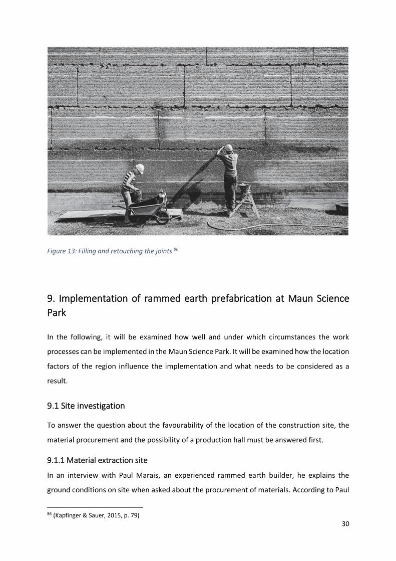
In the last step after joining the wall parts, the gaps between the elements must be sealed
from the outside. For this purpose, they are filled with rammed earth and retouched. Finally,
after the joints have dried and erosion has set in, the building takes on its monolithic
appearance step by step.85
84 Figure based on (Kapfinger & Sauer, 2015, p. 121) 85 (cf. Kapfinger & Sauer, 2015, p. 79)
30
Figure 13: Filling and retouching the joints 86
9. Implementation of rammed earth prefabrication at Maun Science
Park
In the following, it will be examined how well and under which circumstances the work
processes can be implemented in the Maun Science Park. It will be examined how the location
factors of the region influence the implementation and what needs to be considered as a
result.
9.1 Site investigation
To answer the question about the favourability of the location of the construction site, the
material procurement and the possibility of a production hall must be answered first.
9.1.1 Material extraction site
In an interview with Paul Marais, an experienced rammed earth builder, he explains the
ground conditions on site when asked about the procurement of materials. According to Paul
86 (Kapfinger & Sauer, 2015, p. 79)
31
Marais, the soils in Maun are very uniform and primarily sandy with subordinate gravel. The
grains are roundish and the clay content in the soil is about 2-3%. According to Paul Marais,
these soils are not suitable for rammed earth construction. This is not due to the low clay
content, but to the round structure of the grains. The soil does not have enough angular
aggregates to guarantee sufficient load transfer. After trials and tests, he found an aggregate
material that allows the sandy soil to be used. This material is produced when stones are
crushed during concrete production. Paul Marais calls this aggregate Quarry Dust. The grain
structure of the Quarry Dust is triangular and makes it possible to use the soil for rammed
earth construction even with a small addition of 5-20%. The quarry from which the aggregate
material can be obtained is located 70km south-west of Maun in the town of Toteng.
Regarding the yield of the quarry, he says that sufficient Quarry Dust can be extracted. In
addition, he mentions that due to the proximity of the water, there may be significantly larger
deposits of clay on the building site of the Maun Science Park and that the soil can certainly
be considered as a building material.87 The ability to use the soil on site and make it usable
through a small amount of aggregate is a huge advantage for the project's promise of success.
Transport costs and procurement costs are significantly lower, and the environment is not
polluted as much by the extraction and transport of the material.
The fact that the ground of the construction site can be used for manufacturing has a direct
impact on the further steps to establish a prefabrication of rammed earth elements in Maun.
9.1.2 Location of the production hall
After knowing the location of the material, where it is mined and where the aggregates come
from, the next step is to find a suitable location for the production hall. There are two
possibilities for the construction of a production hall. Either you rent an empty warehouse and
convert it to the production of rammed earth elements, or, if there are none available, a
temporary warehouse must be erected for the duration of the construction site. An example
of renting a warehouse in the vicinity of the construction site would be the Ricola
Kräuterzentrum88.
87 (cf. Marais, 2020) 88 (cf. Boltshauser, 2019, p. 203)

32
In Maun, it is unlikely to be able to rent a warehouse in the vicinity of the construction site.
According to Paul Marais, there is a moratorium of zoning in Maun, which restricts factory
space.89
In this case, the option of a temporary construction of the production hall must be considered.
The prerequisite for this is to find a free plot of land for the hall. Due to its enormous size, the
area of land for the Maun Science Park offers the possibility of erecting the production hall
directly on the property and additionally reducing costs and transport routes. Even if the
production hall had a size of 4000m², which is enough to accommodate a production line and
a place to dry the elements, the plot would hardly be utilised to its full capacity. To keep costs
as low as possible, the production hall must be built with the simplest materials. It is important
to ensure that, despite the use of simple materials, there is sufficient protection against
external influences and that the advantages of prefabrication can be used. For the
construction in Maun, costs between 3000 Pula and 6000 Pula per m² can be expected to erect
a temporary construction hall out of simple materials.90
9.2 Technology level of the production hall
After a suitable location for the production has been found, it must be equipped for the
manufacture of the prefabricated parts. During this process, the technical level of equipment
of the production hall is decided. It must be decided for which production processes machines
are used and which are done by hand.
In rammed earth construction, the most time-consuming process is filling the formwork and
then compacting the material. The company Lehm Ton Erde Baukunst GmbH has developed
a machine that automatically fills the formwork and then compacts it directly.91 The machine
reduces the strenuous manual work and lowers the labour costs. The use of the machine
makes sense especially in countries with high labour costs, such as Germany. In Botswana, the
situation is different, and the level of technology does not necessarily mean improvement. In
the region around Maun, labour costs are very low and can hardly be compared to wages in
western countries.
89 (See Appendix, Questions for Paul Marais, 2021) 90 (See Appendix, Questions for Paul Marais, 2021) 91 (cf. Kapfinger & Sauer, 2015, p. 119)
33
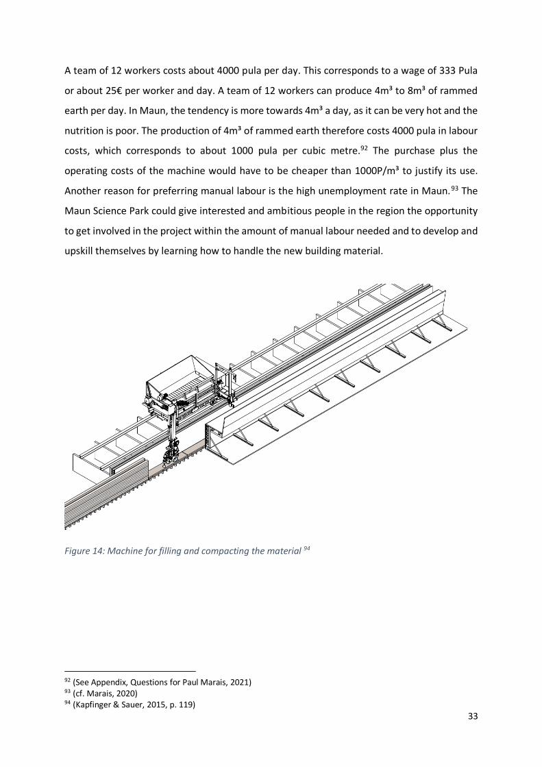
A team of 12 workers costs about 4000 pula per day. This corresponds to a wage of 333 Pula
or about 25€ per worker and day. A team of 12 workers can produce 4m³ to 8m³ of rammed
earth per day. In Maun, the tendency is more towards 4m³ a day, as it can be very hot and the
nutrition is poor. The production of 4m³ of rammed earth therefore costs 4000 pula in labour
costs, which corresponds to about 1000 pula per cubic metre.92 The purchase plus the
operating costs of the machine would have to be cheaper than 1000P/m³ to justify its use.
Another reason for preferring manual labour is the high unemployment rate in Maun.93 The
Maun Science Park could give interested and ambitious people in the region the opportunity
to get involved in the project within the amount of manual labour needed and to develop and
upskill themselves by learning how to handle the new building material.
Figure 14: Machine for filling and compacting the material 94
92 (See Appendix, Questions for Paul Marais, 2021) 93 (cf. Marais, 2020) 94 (Kapfinger & Sauer, 2015, p. 119)
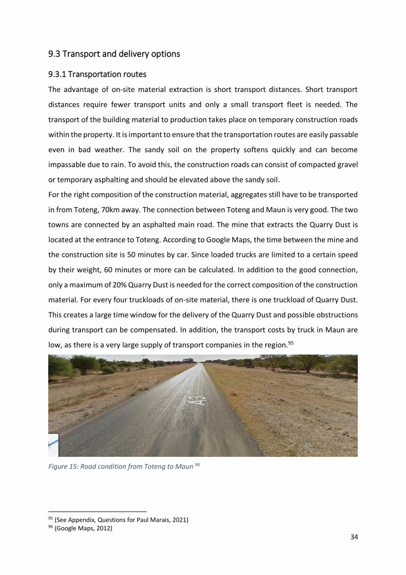
34
9.3 Transport and delivery options
9.3.1 Transportation routes
The advantage of on-site material extraction is short transport distances. Short transport
distances require fewer transport units and only a small transport fleet is needed. The
transport of the building material to production takes place on temporary construction roads
within the property. It is important to ensure that the transportation routes are easily passable
even in bad weather. The sandy soil on the property softens quickly and can become
impassable due to rain. To avoid this, the construction roads can consist of compacted gravel
or temporary asphalting and should be elevated above the sandy soil.
For the right composition of the construction material, aggregates still have to be transported
in from Toteng, 70km away. The connection between Toteng and Maun is very good. The two
towns are connected by an asphalted main road. The mine that extracts the Quarry Dust is
located at the entrance to Toteng. According to Google Maps, the time between the mine and
the construction site is 50 minutes by car. Since loaded trucks are limited to a certain speed
by their weight, 60 minutes or more can be calculated. In addition to the good connection,
only a maximum of 20% Quarry Dust is needed for the correct composition of the construction
material. For every four truckloads of on-site material, there is one truckload of Quarry Dust.
This creates a large time window for the delivery of the Quarry Dust and possible obstructions
during transport can be compensated. In addition, the transport costs by truck in Maun are
low, as there is a very large supply of transport companies in the region.95
Figure 15: Road condition from Toteng to Maun 96
95 (See Appendix, Questions for Paul Marais, 2021) 96 (Google Maps, 2012)

35
9.3.2 Delivery of the construction equipment
Heavy construction equipment is needed for prefabrication in rammed earth construction. In
addition to trucks for transport, excavators are needed to extract the building material and a
crane to move the wall elements on the construction site. According to Paul Marais, this poses
a problem in Maun. There are no excavators and cranes in Maun and the equipment must be
transported from Gaborone, 800 km away. The long distance between Maun and Gaborone
complicates the situation and has several disadvantages.
Firstly, the equipment must be loaded and transported over a long distance. Furthermore, it
can be assumed that the necessary personnel to operate the construction equipment is not
available in Maun and must also travel to Maun to complete the project. Finally, in case of a
defect, it can take several days until technicians of the responsible equipment company are
on site and can repair the damage.
Paul Marais estimates that a crane costs up to 15,000 pula per day and an excavator up to
8,000 pula per day.97 A crane would therefore cost 45 times as much as a single worker.
Nevertheless, it is not inconceivable to get the necessary construction equipment to Maun.
The connection between Maun and Gaborone consists of asphalted roads and can easily be
used by heavy equipment. There is also a direct flight connection between the two cities,
which allows service personnel or construction equipment operators to fly in within 1.5 hours.
It can also be mentioned that rammed earth construction does not need much heavy
construction equipment. Rammed earth construction is largely regulated by the speed of the
compaction process. This process takes a lot of time and so the fleet of heavy equipment can
be kept small.
10. Profitability of prefabrication for the Maun Science Park
The following section deals with the study on the profitability of introducing prefabrication at
the Maun Science Park. It examines which factors of a project can influence the profitability
of prefabrication and add value at Maun Science Park.
97 (See Appendix, Questions for Paul Marais, 2021)
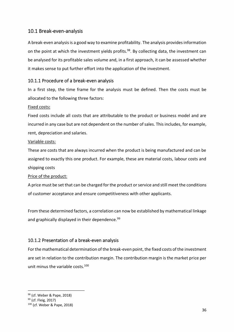
36
10.1 Break-even-analysis
A break-even analysis is a good way to examine profitability. The analysis provides information
on the point at which the investment yields profits.98. By collecting data, the investment can
be analysed for its profitable sales volume and, in a first approach, it can be assessed whether
it makes sense to put further effort into the application of the investment.
10.1.1 Procedure of a break-even analysis
In a first step, the time frame for the analysis must be defined. Then the costs must be
allocated to the following three factors:
Fixed costs:
Fixed costs include all costs that are attributable to the product or business model and are
incurred in any case but are not dependent on the number of sales. This includes, for example,
rent, depreciation and salaries.
Variable costs:
These are costs that are always incurred when the product is being manufactured and can be
assigned to exactly this one product. For example, these are material costs, labour costs and
shipping costs
Price of the product:
A price must be set that can be charged for the product or service and still meet the conditions
of customer acceptance and ensure competitiveness with other applicants.
From these determined factors, a correlation can now be established by mathematical linkage
and graphically displayed in their dependence.99
10.1.2 Presentation of a break-even analysis
For the mathematical determination of the break-even point, the fixed costs of the investment
are set in relation to the contribution margin. The contribution margin is the market price per
unit minus the variable costs.100
98 (cf. Weber & Pape, 2018) 99 (cf. Fleig, 2017) 100 (cf. Weber & Pape, 2018)
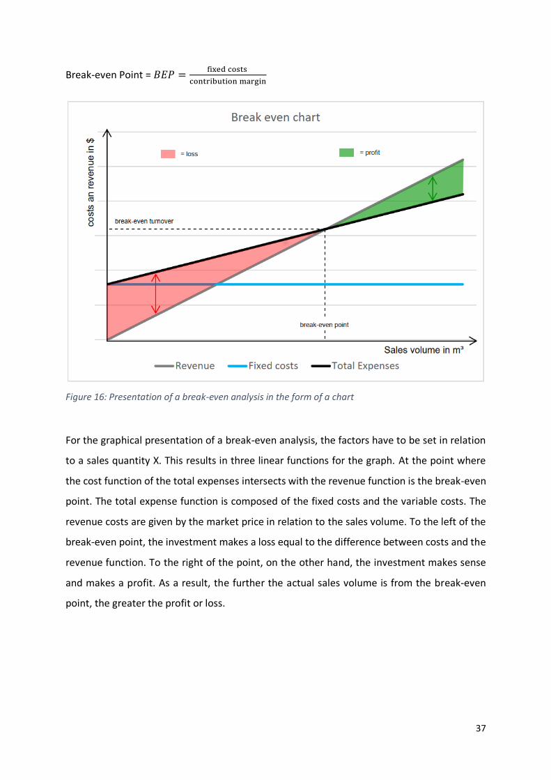
37
Break-even Point = 𝐵𝐸𝑃 =fixed costs
contribution margin
Figure 16: Presentation of a break-even analysis in the form of a chart
For the graphical presentation of a break-even analysis, the factors have to be set in relation
to a sales quantity X. This results in three linear functions for the graph. At the point where
the cost function of the total expenses intersects with the revenue function is the break-even
point. The total expense function is composed of the fixed costs and the variable costs. The
revenue costs are given by the market price in relation to the sales volume. To the left of the
break-even point, the investment makes a loss equal to the difference between costs and the
revenue function. To the right of the point, on the other hand, the investment makes sense
and makes a profit. As a result, the further the actual sales volume is from the break-even
point, the greater the profit or loss.
38
10.2 Application of break-even analysis at Maun Science Park
In this step, the break-even analysis is now applied to the Maun Science Park. For this purpose,
the available data is collected and assigned to the factors of the break-even analysis.
10.2.1 Data collection
The data used here has been adopted based on assumptions made by the local rammed earth
expert Paul Marais. For factors for which Paul Marais did not make any assumptions, values
based on internet research and estimated values are assumed.
Production volume:
To be able to determine a production volume, the design of two students, Felix Dold and Jana-
Marie David, of the architecture course “Bauen im globalen Süden”at the HTWG is used as a
template and for a first mass approach. The following pictures are taken from their
Presentation. For the determination of a production volume, additional dimensional
information in red was added to the design.
The design of the two students proposes a development in the form of a grid. The smallest
unit of the grid is an area of 14m by 14m. Through the juxtaposition of several of these units,
a cityscape is to be created in the course of the project. For an initial massing, this paper
assumes a two-storey building with a wall thicknesses of 50cm and a wall height of 2,5m. In
addition, it is assumed that 25 of these units will be built.
To simplify the measurement, it is assumed that all floor plans are the same and correspond
to the figure below.

39
Figure 17: Dimensioned floor plan of the design 101
From the floor plan and the assumed wall thickness and wall height, the following
measurements are taken for one storey:
Figure 18: Determination of production volume for one floor
101 (Dold & David, 2021)
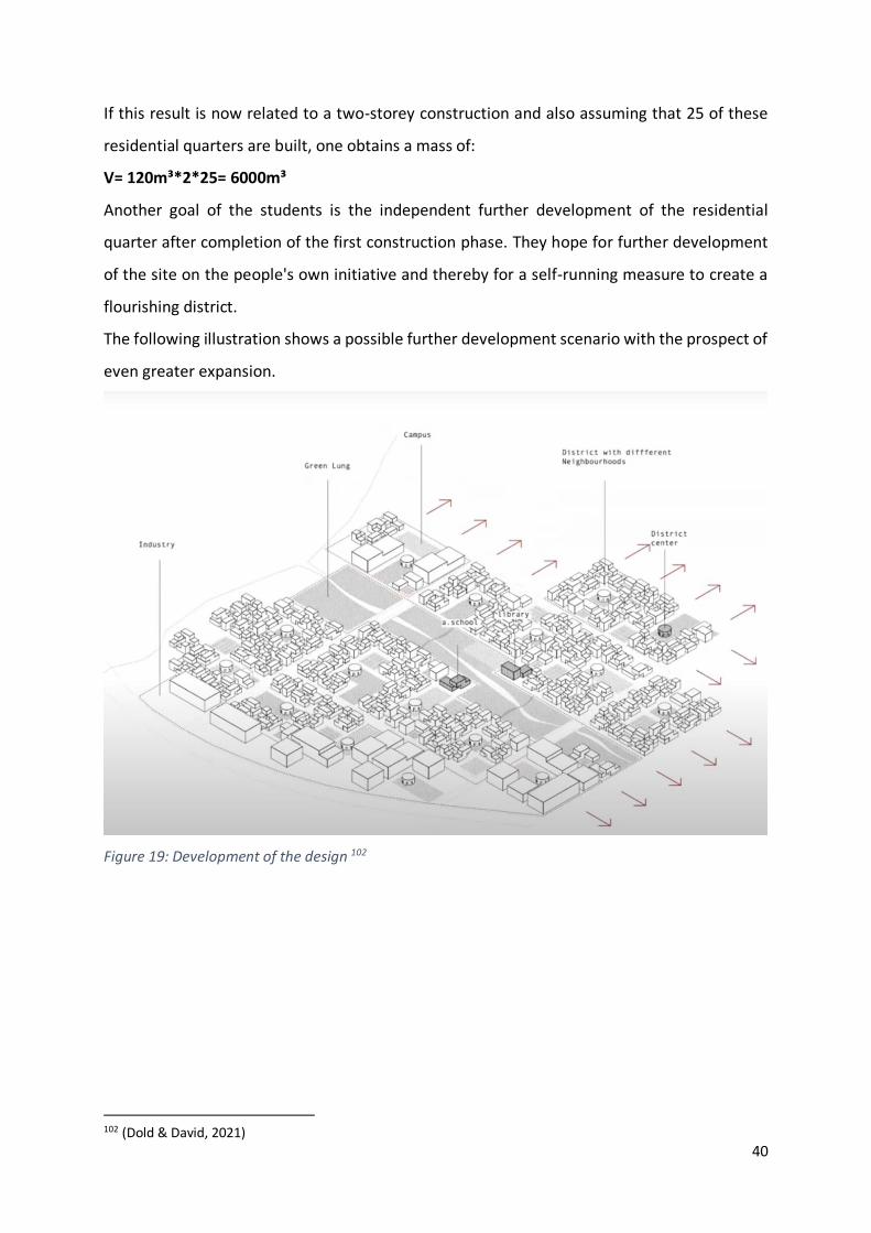
40
If this result is now related to a two-storey construction and also assuming that 25 of these
residential quarters are built, one obtains a mass of:
V= 120m³*2*25= 6000m³
Another goal of the students is the independent further development of the residential
quarter after completion of the first construction phase. They hope for further development
of the site on the people's own initiative and thereby for a self-running measure to create a
flourishing district.
The following illustration shows a possible further development scenario with the prospect of
even greater expansion.
Figure 19: Development of the design 102
102 (Dold & David, 2021)
41
Production time:
Based on a construction volume of 6000m³, the construction time for the rammed earth
production must now be determined. This step is important because the construction time
has a direct influence on the fixed costs. The entire Maun Science Park should be ready for
occupancy within 5 years. A construction period of 2 years is therefore assumed for the
construction of the shell. With 250 working days within one year, 12m³ of rammed earth per
day must be produced and installed to reach the production volume of 6000m³.
Fixed costs:
To determine the fixed costs, the following is assumed:
A production hall of 3000m² is built to produce the elements at a price of 4500Pula/m². The
assumed price is based on an estimate by Paul Marais. The size of the hall should be sufficient
to accommodate a production line of about 40m in length and a sufficiently large room for
drying the finished elements.
For the execution, it is assumed that a crane is needed to move the parts and a wheel loader
is available to accelerate the production and supply the building material. According to Paul
Marais' estimates, a crane costs 15,000 pula a day to rent and a wheel loader about 5,000 pula
a day. The equipment is rented for the entire construction period of 500 days, which ultimately
corresponds to a price of 10,000,000 pula.103
In addition to rental costs and construction costs for the production hall, there are also fixed
costs for providing the formwork material. Assuming a production line of 40m length and 1.5m
height, 120m² of formwork is required per shuttering run. To produce 6000m³ rammed earth,
200 shuttering runs must be carried out. For the purchase of 120m² of formwork a price of the
equivalent of 700,000 Pula is assumed.104 This price is based on internet research and comes
from an Australian company that sells rammed earth formwork. The value serves as a
reference value and it is assumed that formwork material can also be obtained in Botswana.
This may even be at a cheaper price. Due to the possibly cheaper price, no wear factor and
safety factor for repairs are calculated and it is assumed that this formwork kit will survive 200
cycles.
103 (See Appendix, Questions for Paul Marais, 2021) 104 (cf. Rammed earth australia, 2016)
42
Variable costs:
The variable costs are made up as follows:
Paul Marais estimates labour costs for filling and compacting at 1000 pula/m³ in on-site
production. He says that due to the heat and the fact that no one is used to hard work, the
labour costs are higher.105 Prefabrication, however, has the advantage that production is
shielded from external conditions and a much higher work rate can be achieved through the
use of machinery and a simpler formwork concept in the form of an endless wall. It is assumed
that due to these advantages, labour costs can be reduced to one third including formwork.
Labour costs therefore amount to only 335 pula/m³.
The costs for the building material are comparatively low. To obtain the material that can be
extracted on site, it is assumed that an earth-moving machine costs 4000Pula per day. This
equipment has an output of 100m³ to 200m³ per day. This corresponds to costs of about 30
pula/m³ at average working speed.106 Quarry dust from the Toteng mine can be purchased for
about 83 pula/m3. This is based on the estimate of Paul Marais that 6m³ could cost about
2500Pula including the assumption that only 20% of the Quarry Dust is used in the building
material.107
Bid amount or price:
The last thing to do is to set a price for the production unit. This results from market demand
and supply. For rammed earth production, Paul Marais calculates a price of 4000 pula/m³.108
For the Maun Science Park, this would result in revenues of 24,000,000 pula based on the
previously determined production volume.
105 (See Appendix, Questions for Paul Marais, 2021) 106 (Bühler, 2021 02 05 Maun Science Park Budget Phase 1 w Ron Bakker, 2021) 107 (See Appendix, Questions for Paul Marais, 2021) 108 (See Appendix, Questions for Paul Marais, 2021)

43
Summary of the data collection:
Table 1: Data collection
Unit Total
Construction volume 6000 m³
Total offer 24.000.000 Pula
price 4.000 Pula/m³
revenue 24.000.000 Pula
variable expenses 448 Pula/m³ 2.688.000 Pula
Labour costs 335 Pula/m³
Building material (on-site) 30 Pula/m³Building material (Quarry Dust) 83 Pula/m³
contribution margin 3.552 Pula/m³ 21.312.000 Pula
fixed expenses 24.200.000 Pula
Rent construction equipment 10.000.000 Pula
Construction production hall 13.500.000 PulaFormwork costs 700.000 Pula

44
10.2.2 Interpretation
After all the necessary data has been collected, it can now be displayed in a chart in relation
to each other.
Figure 20: Break-Even Analysis for the Maun Science Park
Table 2: Break-Break-Even Analysis for the Maun Science Park
The break-even analysis shows that the investment is not profitable up to a production volume
of 6000m³. The introduction of prefabrication, based on the assumptions made, would result
0 Pula
5.000.000 Pula
10.000.000 Pula
15.000.000 Pula
20.000.000 Pula
25.000.000 Pula
30.000.000 Pula
35.000.000 Pula
40.000.000 Pula
0 m³ 1000 m³ 2000 m³ 3000 m³ 4000 m³ 5000 m³ 6000 m³ 7000 m³ 8000 m³ 9000 m³
Break even chart prefabrication
Revenue Fixed costs Total Expenses
Units Revenue Fixed costs Total Expenses Profit
0 m³ 0 Pula 24.200.000 Pula 24.200.000 Pula -24.200.000 Pula
1000 m³ 4.000.000 Pula 24.200.000 Pula 24.648.000 Pula -20.648.000 Pula
2000 m³ 8.000.000 Pula 24.200.000 Pula 25.096.000 Pula -17.096.000 Pula
3000 m³ 12.000.000 Pula 24.200.000 Pula 25.544.000 Pula -13.544.000 Pula
4000 m³ 16.000.000 Pula 24.200.000 Pula 25.992.000 Pula -9.992.000 Pula
5000 m³ 20.000.000 Pula 24.200.000 Pula 26.440.000 Pula -6.440.000 Pula
6000 m³ 24.000.000 Pula 24.200.000 Pula 26.888.000 Pula -2.888.000 Pula
7000 m³ 28.000.000 Pula 24.200.000 Pula 27.336.000 Pula 664.000 Pula
8000 m³ 32.000.000 Pula 24.200.000 Pula 27.784.000 Pula 4.216.000 Pula
9000 m³ 36.000.000 Pula 24.200.000 Pula 28.232.000 Pula 7.768.000 Pula
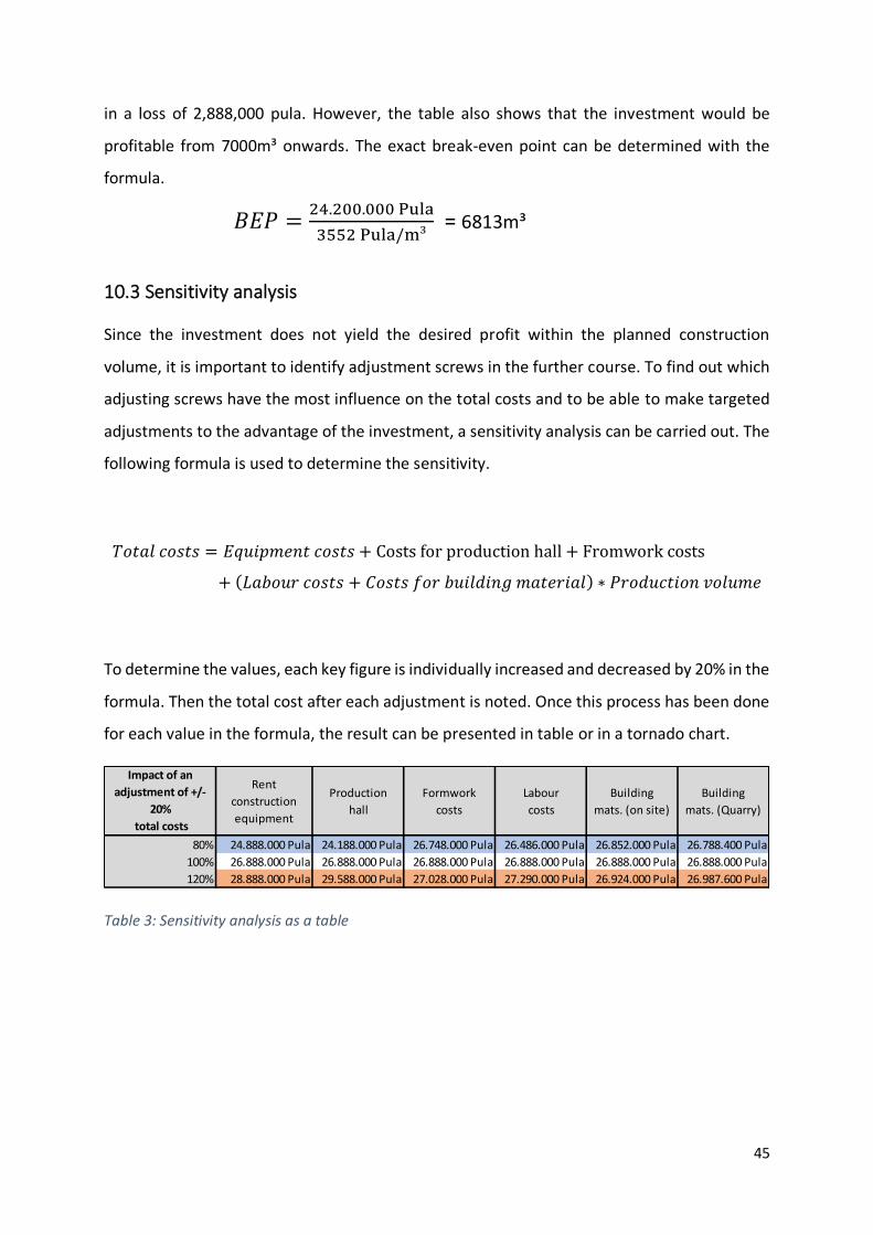
45
in a loss of 2,888,000 pula. However, the table also shows that the investment would be
profitable from 7000m³ onwards. The exact break-even point can be determined with the
formula.
𝐵𝐸𝑃 =24.200.000 Pula
3552 Pula/m³ = 6813m³
10.3 Sensitivity analysis
Since the investment does not yield the desired profit within the planned construction
volume, it is important to identify adjustment screws in the further course. To find out which
adjusting screws have the most influence on the total costs and to be able to make targeted
adjustments to the advantage of the investment, a sensitivity analysis can be carried out. The
following formula is used to determine the sensitivity.
𝑇𝑜𝑡𝑎𝑙 𝑐𝑜𝑠𝑡𝑠 = 𝐸𝑞𝑢𝑖𝑝𝑚𝑒𝑛𝑡 𝑐𝑜𝑠𝑡𝑠 + Costs for production hall + Fromwork costs
+ (𝐿𝑎𝑏𝑜𝑢𝑟 𝑐𝑜𝑠𝑡𝑠 + 𝐶𝑜𝑠𝑡𝑠 𝑓𝑜𝑟 𝑏𝑢𝑖𝑙𝑑𝑖𝑛𝑔 𝑚𝑎𝑡𝑒𝑟𝑖𝑎𝑙) ∗ 𝑃𝑟𝑜𝑑𝑢𝑐𝑡𝑖𝑜𝑛 𝑣𝑜𝑙𝑢𝑚𝑒
To determine the values, each key figure is individually increased and decreased by 20% in the
formula. Then the total cost after each adjustment is noted. Once this process has been done
for each value in the formula, the result can be presented in table or in a tornado chart.
Table 3: Sensitivity analysis as a table
Impact of an
adjustment of +/-
20%
total costs
Rent
construction
equipment
Production
hall
Formwork
costs
Labour
costs
Building
mats. (on site)
Building
mats. (Quarry)
80% 24.888.000 Pula 24.188.000 Pula 26.748.000 Pula 26.486.000 Pula 26.852.000 Pula 26.788.400 Pula
100% 26.888.000 Pula 26.888.000 Pula 26.888.000 Pula 26.888.000 Pula 26.888.000 Pula 26.888.000 Pula
120% 28.888.000 Pula 29.588.000 Pula 27.028.000 Pula 27.290.000 Pula 26.924.000 Pula 26.987.600 Pula

46
Figure 21: Sensitivity analysis as a tornado chart
The analysis shows that the equipment costs and the construction of a production hall have
the biggest influence on the total costs. The labour costs and formwork costs already have less
influence on the total costs. The influence of the cost of the building material is almost
marginal. With the help of this analysis, management can now weigh up which factors need
to be given more attention and where it is worth making improvements to the concept.
10.4 Recommendations for Management
The sensitivity analysis shows the urgency of adjusting the influencing factors. In the following,
management recommendations and precise targets for achieving profitability are formulated.
1. Reduction of the fixed costs for the production hall
The construction of the production hall is the biggest cost driver. This is largely dependent on
two factors. Firstly, it results from the required storage space and secondly from the calculated
price. By creating a well-thought-out supply system between production, drying and assembly,
it would be conceivably possible to reduce the storage area. When developing the concept, it
is important to ensure that the standing times for drying the elements are not exceeded and
that they can be installed directly after their drying time. The production speed must be
coordinated with the installation time. The goal is to fully utilise the storage area at any point
in the course of the project. So as soon as a dry element is transported to the construction site
for installation, an element that has just been produced must take its storage space.
23 Pula 24 Pula 25 Pula 26 Pula 27 Pula 28 Pula 29 Pula 30 Pula
Rent construction equipment
Production hall
Formwork costs
Labour costs
Building mats. (on site)
Building mats. (Quarry)
Total costs Million
Sensitivity analysis
-20%
+20%
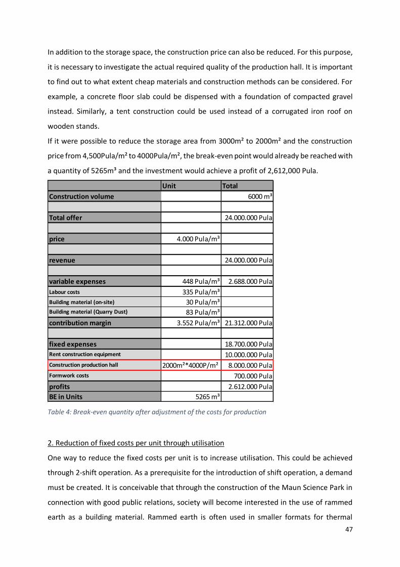
47
In addition to the storage space, the construction price can also be reduced. For this purpose,
it is necessary to investigate the actual required quality of the production hall. It is important
to find out to what extent cheap materials and construction methods can be considered. For
example, a concrete floor slab could be dispensed with a foundation of compacted gravel
instead. Similarly, a tent construction could be used instead of a corrugated iron roof on
wooden stands.
If it were possible to reduce the storage area from 3000m² to 2000m² and the construction
price from 4,500Pula/m² to 4000Pula/m², the break-even point would already be reached with
a quantity of 5265m³ and the investment would achieve a profit of 2,612,000 Pula.
Table 4: Break-even quantity after adjustment of the costs for production
2. Reduction of fixed costs per unit through utilisation
One way to reduce the fixed costs per unit is to increase utilisation. This could be achieved
through 2-shift operation. As a prerequisite for the introduction of shift operation, a demand
must be created. It is conceivable that through the construction of the Maun Science Park in
connection with good public relations, society will become interested in the use of rammed
earth as a building material. Rammed earth is often used in smaller formats for thermal
Unit Total
Construction volume 6000 m³
Total offer 24.000.000 Pula
price 4.000 Pula/m³
revenue 24.000.000 Pula
variable expenses 448 Pula/m³ 2.688.000 Pula
Labour costs 335 Pula/m³
Building material (on-site) 30 Pula/m³Building material (Quarry Dust) 83 Pula/m³
contribution margin 3.552 Pula/m³ 21.312.000 Pula
fixed expenses 18.700.000 Pula
Rent construction equipment 10.000.000 Pula
Construction production hall 2000m²*4000P/m² 8.000.000 Pula
Formwork costs 700.000 Pula
profits 2.612.000 Pula
BE in Units 5265 m³

48
regulation, for aesthetic reasons or because of its good absorption behaviour in residential
construction. If people in the region become aware of the positive aspects, a demand for
prefabricated wall elements for private housing construction could arise. The Maun Science
Park could meet this demand by using the equipment in a 2-shift operation and deliver the
elements directly to the customers' door. It is important to note that the production of the
elements for external customers is considered a separate business model. This means that the
fixed costs can be divided between the Maun Science Park and the production of small-format
walls for external customers. On average, therefore, the fixed costs per unit decrease.
Assuming that an additional 1000m³ of rammed earth could be produced for customers
outside the Maun Science Park, the average fixed costs would decrease by 1/7. In total, the
fixed costs would then only amount to 20,742,857 pula and the break-even point would be
reached at 5840m³.
Table 5: Break-even quantity after increase in utilisation
Unit Total
Construction volume 6000 m³
Total offer 24.000.000 Pula
price 4.000 Pula/m³
revenue 24.000.000 Pula
variable expenses 448 Pula/m³ 2.688.000 Pula
Labour costs 335 Pula/m³
Building material (on-site) 30 Pula/m³Building material (Quarry Dust) 83 Pula/m³
contribution margin 3.552 Pula/m³ 21.312.000 Pula
fixed expenses 24.200.000P*6/7 20.742.857 Pula
Rent construction equipment 8.571.429 Pula
Construction production hall 11.571.429 PulaFormwork costs 600.000 Pula
profits 569.143 Pula
BE in Units 5840 m³
49
3. Low variable costs due to quality items
Compared to fixed costs, variable costs are less significant. Nevertheless, possibilities for
increasing efficiency are to be worked out here as well. One aim of the project is to give society
the opportunity to participate and gain new perspectives for the future through up-skilling. In
order to accelerate the learning process and reduce labour costs through higher efficiency,
workers can be trained in advance and accompanied by experienced mentors during the
construction process. In addition, the training of the workers increases quality and revision
work can be avoided.
Another way to reduce variable costs is to reduce the cost of building materials. Although
these have the least influence on total costs, they should not be neglected. It is important to
keep the costs low by preparing the material correctly and avoiding unnecessary watering
through long laying times on warm days.
11. Summary and Conclusion
The Maun Science Park is a housing project in Botswana in the city of Maun. It addresses the
emerging issues of the 21st century and seeks to enable resilient housing in the future through
the use of sustainable building materials and the application of modern technology.
This thesis addresses the use of rammed earth for the project and investigates the
implementation of prefabrication of this building material on the profitability. For this
purpose, the handling of the building material and the specific properties were discussed in a
first step. To create load-bearing walls, the loose building material is filled into the formwork
and compacted by pressure. The advantage of using rammed earth as a building material is
mainly due to its environmental friendliness using excavated earth for production and its small
CO2 footprint. Rammed earth also has potential in terms of building physics. These include
thermal insulation, ability to regulate moisture and high fire resistance. From a structural point
of view, the building material has deficits, but these can be eliminated through appropriate
weather protection as well as through well thought-out detailed solutions such as reinforced
lintels. Also, the building material has already been used in prefabrication and the first
standardisations have taken place through production on an endless wall.
50
Furthermore, the implementation of rammed earth prefabrication for the Maun Science Park
was investigated. It can be concluded that the infrastructure of the region is well developed,
the sourcing of building materials is easy to implement and the costs for labour are low. On
the other hand, a warehouse required for the construction project cannot be rented but must
be newly built. In addition, the acquisition of heavy construction equipment is difficult
because there are no corresponding local companies.
Based on this, the expenses for implementation were quantified in order to be able to carry
out a profitability study. The application of a break-even analysis showed that the investment
in prefabrication is not profitable within the assumed production volume. This is mainly due
to the high fixed costs in relation to the total costs. A subsequent sensitivity analysis showed
that the new construction of the production hall and the acquisition of the heavy construction
equipment are the main cost drivers.
From this, recommendations for action were formulated that provide for a cost reduction
regarding both main cost drivers as well as other variable costs.
A limitation of this work is the little available expertise on the building material in
prefabrication. Rammed earth in prefabrication is mainly practiced in Europe and there are no
reference projects or experience values for the transfer to the South African continent. In
addition, the project is in a very early planning phase and the ideas are still far from precise
definitions. The lack of experience as well as imprecise project definitions led to the fact that
many values had to be assumed and estimated and the determination of profitability must be
regarded critically. With definitions becoming clearer in the later course of the project, the
determination should be repeated for more accurate statements.
51
Bibliography
Albus, J. (2017). Prefabrication and Automated Processes in Residential Contrsuction. Berlin: DOM
publishers.
Average Day And Night Temperature In Maun In Celsius. (2019). Retrieved 01 02, 2021, from
Weather & Climate: https://weather-and-climate.com/average-monthly-min-max-
Temperature,Maun,Botswana
Bayrisches Landesamt für Umwelt. (2020). Bodenbestandteile. Retrieved Dezember 14, 2020, from
https://www.lfu.bayern.de/boden/erdausstellung/bodenbestandteile/index.htm
Boltshauser, R. (2019). Pisé-Stampflehm Tradition und Potenzial. Zürich: Triest.
Botswana- allgemeine Informationen. (2021). Retrieved 02 06, 2021, from info botswana:
https://www.info-botswana.com/de/info/allgemeine-informationen
Breda, A. (2020, 01 02). Gescheiter Staat. Retrieved 02 06, 2021, from Spiegel:
https://www.spiegel.de/politik/ausland/botswana-ist-afrikas-erfolgsgeschichte-was-das-
land-richtig-macht-a-1301761.html
Bühler, M. (2020). Project Goals. Lecture international cooperations / Project Goals / HTWG
Konstanz.
Bühler, M. (2020). The Vision. Lecture international cooperations / The vision / HTWG Konstanz.
Bühler, M. (2021, 02 20). 2021 02 05 Maun Science Park Budget Phase 1 w Ron Bakker. Retrieved
from
https://www.youtube.com/watch?v=PfGu9glGR90&feature=youtu.be&ab_channel=Michael
MaxBuehler
Ciancio, D. (2015, 04 29). Cheap, tough and green: why aren’t more buildings made of rammed earth.
Retrieved 02 22, 2021, from The Conversation: https://theconversation.com/cheap-tough-
and-green-why-arent-more-buildings-made-of-rammed-earth-38040
city population. (2020, 10 07). Retrieved 02 06, 2021, from Botswana:
http://www.citypopulation.de/de/botswana/
Dold, F., & David, J.-M. (2021). Entwurf für den Maun Science Park. Schlusspräsentation Bauen im
globalen Süden 20210202 1309 1. Retrieved from
https://www.youtube.com/watch?v=3xTNzAyWmf8&feature=youtu.be&ab_channel=Michae
lMaxBuehler
Easton, D. (1996). The rammed earth house. White River Junction, Vermont, United States of
America: Chelsea Green Publishing Company.
Fleig, J. (2017). Investitionsrechnung und Methoden zur Bewertung. Retrieved 02 11, 2021, from
business-wissen: https://www.business-wissen.de/hb/break-even-analyse-berechnung-und-
beispiele/
Google Maps. (2012, 05). Retrieved 02 22, 2021, from https://www.google.de/maps/@-
20.2589617,23.1313172,3a,75y,64.68h,84.91t/data=!3m6!1e1!3m4!1sfi9a49cbW03UkyUk2g
L-DQ!2e0!7i13312!8i6656

52
Grimm, R. (2019, 04 25). Was ist Stampflehm? Retrieved 02 07, 2021, from Baustoff Wissen:
https://www.baustoffwissen.de/baustoffe/baustoffknowhow/grundstoffe-des-bauens/was-
ist-stampflehm-innenwaende-bauweise-eigenschaften-wohngesundheit/
Kapfinger, O., & Sauer, M. (2015). Martin Rauch Gebaute Erde Gestalten & Konstruieren mit
Stampflehm. Immenstadt: DETAIL.
Knaack, U., Chung-Klatte, S., & Hasselbach, R. (2012). Systembau Prinzipien der Konstruktion. Basel:
Birkhäuser.
Koulolias, V. (2020). Lecture international cooperations / Presentation Vasilis / HTWG Konstanz.
Maun research and educational facility for sustainable habitats.
Marais, P. (2020). Zoom Q&A with Paul Marais on Rammed Earth. Internal lecture HTWG Konstanz.
(M. Bühler, & Students, Interviewers)
Maun Science Park. (2020). Retrieved 02 15, 2021, from
https://www.maunsciencepark.com/home.html
Rammed earth australia. (2016, 06). Retrieved 02 20, 2021, from
http://www.rammedearthaustralia.com.au/documents/large_rammed_earth_formwork_kit
_2016.pdf
Röhlen, U., & Ziegert, C. (2020). Lehmbau-Praxis: Planung und Ausführung. Berlin; Wien; Zürich:
Beuth.
United Nations Development Programme. (2019). Retrieved 02 06, 2021, from Human Development
Reports: http://www.hdr.undp.org/en/indicators/44206
Weber, J., & Pape, U. (2018). Break-Even-Analyse. Retrieved 02 11, 2021, from Gabler
Wirtschaftslexikon: https://wirtschaftslexikon.gabler.de/definition/break-even-analyse-
31893/version-255441

III
Declaration of autorship
I, Tim Schmoll, hereby declare that I have independently composed this thesis and that
I have not used any other resources than those indicated.
I assure that I have marked the adoption of literal quotations, tables, drawings and
pictures from literature or other sources (Internet) as well as the use of the thoughts
of other authors at the appropriate places within the work.
Konstanz, 02/28/2021 Tim Schmoll
Tim
Textfeld
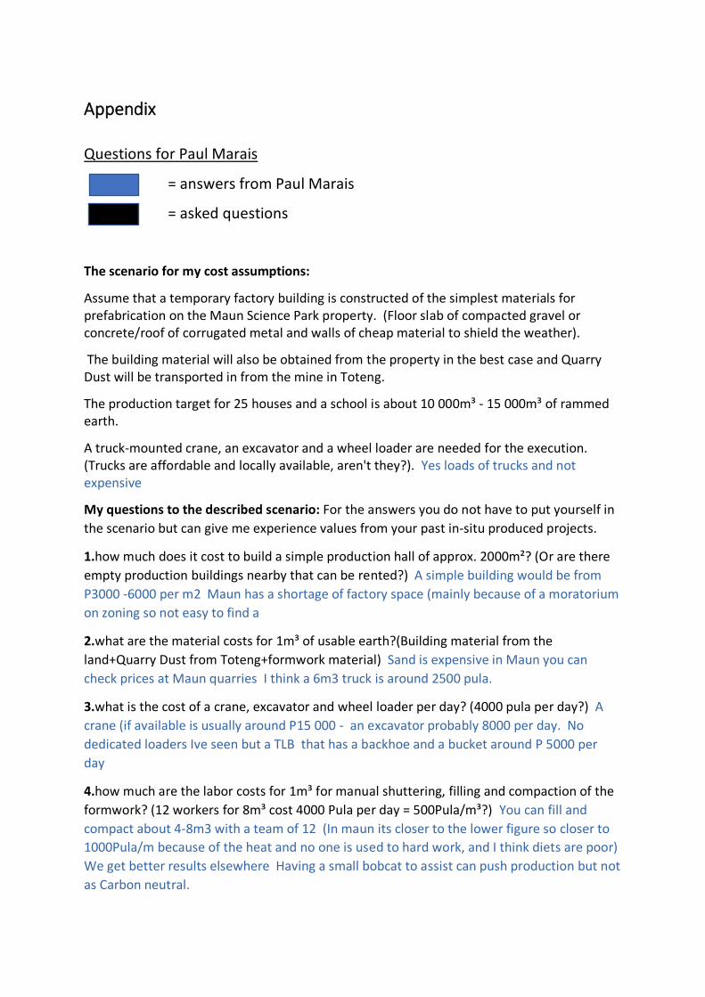
IV
Appendix
Questions for Paul Marais
= answers from Paul Marais
= asked questions
The scenario for my cost assumptions:
Assume that a temporary factory building is constructed of the simplest materials for prefabrication on the Maun Science Park property. (Floor slab of compacted gravel or concrete/roof of corrugated metal and walls of cheap material to shield the weather).
The building material will also be obtained from the property in the best case and Quarry Dust will be transported in from the mine in Toteng.
The production target for 25 houses and a school is about 10 000m³ - 15 000m³ of rammed earth.
A truck-mounted crane, an excavator and a wheel loader are needed for the execution. (Trucks are affordable and locally available, aren't they?). Yes loads of trucks and not expensive
My questions to the described scenario: For the answers you do not have to put yourself in
the scenario but can give me experience values from your past in-situ produced projects.
1.how much does it cost to build a simple production hall of approx. 2000m²? (Or are there
empty production buildings nearby that can be rented?) A simple building would be from
P3000 -6000 per m2 Maun has a shortage of factory space (mainly because of a moratorium
on zoning so not easy to find a
2.what are the material costs for 1m³ of usable earth?(Building material from the
land+Quarry Dust from Toteng+formwork material) Sand is expensive in Maun you can
check prices at Maun quarries I think a 6m3 truck is around 2500 pula.
3.what is the cost of a crane, excavator and wheel loader per day? (4000 pula per day?) A
crane (if available is usually around P15 000 - an excavator probably 8000 per day. No
dedicated loaders Ive seen but a TLB that has a backhoe and a bucket around P 5000 per
day
4.how much are the labor costs for 1m³ for manual shuttering, filling and compaction of the
formwork? (12 workers for 8m³ cost 4000 Pula per day = 500Pula/m³?) You can fill and
compact about 4-8m3 with a team of 12 (In maun its closer to the lower figure so closer to
1000Pula/m because of the heat and no one is used to hard work, and I think diets are poor)
We get better results elsewhere Having a small bobcat to assist can push production but not
as Carbon neutral.

V
5.what is the time cost for shuttering work in relation to filling and tamping? It depends on
complexity We often have a formwork team that stays ahead of our stamping team. One
team can easily strip and refit whilst the other team stamps. A clever formwork design can
really make a difference
6.how much money can be charged for the construction of a rammed earth wall? I know you
are 15% more expensive than the traditional construction method., but how much money is
charged to build a masonry wall or with similar products? (Does a sum of 30,000,000 pula for
15,000m³ sound reasonable? Only creation of the shell without plinth, roof and finishing). I
am not sure on standard rates (I used to have a book but they have stopped issuing it. We
are charging up to P4000 per cube on small high quality jobs. I think half this is reasonable
which is what you are suggesting. Costs are done on a per meter rate so hard to compare as
brickwork must be plastered, painted and then it still has no comparable thermal
performance. If you manage to get to 1000 per cube you will be really competitive.

VI
Table collection for sensitivity analysis

VII