tiling 1124DS-002.0
288
Direct Adhered Ceramic Tile, Stone, Masonry Veneer, and Thin Brick Facades – Technical Manual
-
Upload
andresboy123 -
Category
Documents
-
view
54 -
download
1
description
tiling
Transcript of tiling 1124DS-002.0

Direct Adhered Ceramic Tile, Stone, Masonry Veneer, and Thin Brick Facades – Technical Manual
©2011 LATICRETE International, Inc.All trademarks shown are the intellectual properties of their respective owners.
Corporate Headquarters:
LATICRETE International, Inc.One LATICRETE Park NorthBethany, CT 06524-3423 USA1.800.243.4788+1.203.393.0010
www.laticrete.com
Asia Pacific: +852.2526.6660
Australia: +61.3.9933.6111
China: +86.21.5789.3300
Europe: +34.96.649.1908
India: +91.40.3041.3100
Latin America: +1.203.393.0010
Middle East: +971.7.244.6396
South East Asia: +65.6515.3028
Facades Technical Design Manual
LATICRETE Technical Services Department
9DS-002.0-0911
®
U.S. $19.99

Cover Photo: Project – LATICRETE International World Headquarters, Bethany, CT, 2008
Description: 23 x 27 x 1" (585 x 685 x 25 mm) Blue Pearl Granite and White Granite utilizing two installation methods. Spot bonding with LATAPOXY® 310 Stone Adhesive to concrete masonry units, and direct bond to LATICRETE® Hydro Ban® over concrete masonry units using LATICRETE 254 Platinum.
Architect: Pustola & Associates, Naugatuck, CT, USA
© 1998, 2011 LATICRETE International, Inc. All rights reserved. No part of this publication (except for previously published articles and industry references) may be reproduced or transmitted in any form or by any means, electronic or mechanical, without the written permission of LATICRETE International, Inc. The information and recommendations contained herein are based on the experience of the author and LATICRETE International, Inc. While we believe the information presented in these documents to be correct, LATICRETE International and its employees assume no responsibility for its accuracy or for the opinions expressed herein. The information contained in this publication should not be used or relied upon for any specific application or project without competent examination by qualified professionals and verification of its accuracy, suitability, and applicability. Users of information from this publication assume all liability arising from such use.
Direct Adhered Ceramic Tile, Stone, Masonry Veneer, and Thin Brick Facades – Technical Manual ©2011 LATICRETE International, Inc.

1Direct Adhered Ceramic Tile, Stone, Masonry Veneer, and Thin Brick Facades – Technical Design Manual
DIRECT ADHERED CERAMIC TILE, STONE, MASONRY VENEER, AND THIN BRICK FACADESTECHNICAL DESIgN MANuALRichard P. Goldberg, Architect AIA, CSI

2 Direct Adhered Ceramic Tile, Stone, Masonry Veneer, and Thin Brick Facades – Technical Design Manual

3Direct Adhered Ceramic Tile, Stone, Masonry Veneer, and Thin Brick Facades – Technical Design Manual
SECTION 1 INTRODuCTION........................................................................................91.1 Preface
1.2 Why Use The Direct Adhered Method?
1.3 Brief History of Ceramic tile, stone, masonry veneer, and thin brick Facades
1.4 Summary – Content of Manual
1.5 Historical Case Study
SECTION 2 EXTERIOR WALL CONCEPTS ....................................................................152.1 Function of Exterior Walls
2.2 Types of Exterior Wall Structures
Bearing Wall
Non-bearing Wall
Curtain Wall
2.3 Types of Exterior Wall Construction
Barrier Wall
Cavity Wall
Pressure-equalized Rain Screen Wall
Future Technology – Dynamic Buffer Zone
2.4 References
SECTION 3 TYPES OF DIRECT ADHERED WALL CONSTRuCTION..............................213.0 On Site (In-situ) Construction
3.1 Concrete Masonry Unit Substrate
Barrier Wall
Cavity and Pressure-Equalized Wall
Inner Cavity Concrete Masonry
Inner Cavity Light Gauge Steel Framing
3.2 Clay Masonry Unit Substrate
3.3 Light Gauge Steel Framing
Cement Backer Unit Substrate
Lath and Cement Plaster Substrate
Corrugated Steel Substrate
3.4 Reinforced Cast-in-place Concrete Substrate
3.5 Pre-cast Concrete Panels – Positive and Negative Cast Methods
Glass Fiber Reinforced Concrete (GFRC) Panels
3.6 Architectural Details
Table of Contents

4 Direct Adhered Ceramic Tile, Stone, Masonry Veneer, and Thin Brick Facades – Technical Design Manual
Table of Contents
3.7 Case Study – Saskatoon City Hospital – Pre-cast Concrete and Ceramic Tile.............................65
3.8 References
SECTION 4 STRuCTuRAL AND ARCHITECTuRAL CONSIDERATIONS......................794.1 Structural Considerations – Types of Structural Movement
Live and Dead Loads
Thermal Movement
Moisture Expansion
Drying Shrinkage
Elastic Deformation
Creep
Differential Settlement
4.2 Architectural Considerations – Components of the Exterior Wall Assembly
Windows and Window Maintenance Systems
Thermal Control – Insulation
Moisture Control – Waterproofing, Flashing and Drainage Planes
Movement Joints
Fire Resistance and Containment
Acoustical Control
Roofing and Parapet Walls
4.3 References
SECTION 5 SuBSTRATES..............................................................................................975.1 Criteria for Selection of Substrates
5.2 Types of Substrates
5.3 Substrate Preparation – Design and Construction Requirements
5.4 Substrate Preparation – Cleaning Equipment and Procedures
5.5 References
SECTION 6 SELECTION OF EXTERNAL CLADDINg MATERIAL ................................1136.1 Criteria for Selection of Ceramic Tile, Stone, Masonry Veneer and Thin Brick
6.2 Ceramic Tile
6.3 Stone and Agglomerates
6.4 Adhered Manufactured Masonry Veneer
6.5 Thin Brick Masonry
6.6 Cladding Selection – Moisture Sensitivity, Color, Temperature
6.7 References

5Direct Adhered Ceramic Tile, Stone, Masonry Veneer, and Thin Brick Facades – Technical Design Manual
Table of Contents
SECTION 7 INSTALLATION MATERIALS AND METHODS – ADHESION gROuTINg OF CERAMIC TILE, STONE, MASONRY VENEER, AND THIN BRICK ...................1297.1 Adhesive Performance and Selection Criteria
7.2 Types of Adhesives
7.3 Methods of Adhesive – Cladding Installation
7.4 Cladding Installation Equipment and Procedures
7.5 Grout and Sealant Joint Materials and Methods of Installation
7.6 Post-installation Cleaning
7.7 References
SECTION 8 INDuSTRY STANDARDS, BuILDINg REguLATIONS AND SPECIFICATIONS...................1538.1 Background
8.2 Building Codes and Regulations
8.3 Industry Standards
8.4 Guideline Specifications
8.5 References
Index
SECTION 9 QuALITY ASSuRANCE, TESTINg, INSPECTION MAINTENANCE PROCEDuRES ............... 2019.1 Quality Assurance Procedures
9.2 Preventative and Corrective Maintenance
9.3 Protection and Sealing
9.4 Non-destructive Testing
Visual Inspection
Computer Modeling (Finite Element Analysis FEA)
Tap (Acoustic Impact) Testing
Infrared Imaging (Thermographic Scanning)
Ultrasonic Pulse Velocity and Echo Testing
Moisture Content Testing
Salt Contamination Testing
9.5 Destructive Testing
Tensile Pull Strength Testing
Core Drilling
Shear Bond Testing
9.6 Types, Causes and Remediation of Defects
Staining and Weathering
Fluid Migration

6 Direct Adhered Ceramic Tile, Stone, Masonry Veneer, and Thin Brick Facades – Technical Design Manual
Table of Contents
Efflorescence
Cracking
Delamination and Adhesive Bond Failure
Movement Joint and Grout Failure
9.7 Technical Articles
The Importance of Shear Bond Strength Characteristics of Polymer-modified Adhesives
Finite Element Analysis article
9.8 References
SECTION 1O TILE AND STONE FAÇADE CASE STuDY AND TROuBLESHOOTINg .............................. 24110.1 Case Study – Brooklyn Children’s Museum, Brooklyn, NY
10.2 Troubleshooting Pictorial
SECTION 1O APPENDIX ................................................................................................................ 26911.1 Frequently Asked Questions (FAQ)
11.2 Glossary
11.3 Resource Guide – Trade Organizations, Technical References
Index

7Direct Adhered Ceramic Tile, Stone, Masonry Veneer, and Thin Brick Facades – Technical Design Manual
LATICRETE International, Inc., a manufacturer of ceramic tile, stone and brick masonry installation systems, has long recognized the need for a technical manual to provide guidelines and recommendations for the design, specification, and installation of direct adhered ceramic tile, stone, and thin brick cladding for exterior facades. Technical advances in materials, manufacturing, and construction methods have expanded the role of this type of application ever since the development of adhesive mortars in the 1950’s. In keeping with their position as an industry leader, LATICRETE International is publishing this second edition of the Direct Adhered Ceramic Tile, Stone and Thin Brick Facades Technical Design Manual to make state-of-the-art information and technology available to architects, engineers, construction professionals, and manufacturers in the ceramic tile, stone and thin brick industries. It is also the goal of this publication to encourage new ideas, research, and building regulations for the purpose of improving the future of this construction technology and the ceramic tile, stone and brick industries.
Preface

8 Direct Adhered Ceramic Tile, Stone, Masonry Veneer, and Thin Brick Facades – Technical Design Manual

Section 1: Introduction
9Direct Adhered Ceramic Tile, Stone, Masonry Veneer, and Thin Brick Facades – Technical Design Manual
Photo: Covelli Enterprises Building – Warren, OH 2007 Architect: Phillips/Sekanick Architecture, Warren, OH and Tile Contractor: Barron Tile Co., Youngstown, OH.Description: Porcelain tile over concrete masonry and light gauge steel framing.

10 Direct Adhered Ceramic Tile, Stone, Masonry Veneer, and Thin Brick Facades – Technical Design Manual
Section 1: Introduction
SECTION 1 INTRODUCTION1.1 PREFACELATICRETE International, a manufacturer of ceramic tile, stone, masonry veneer and thin brick masonry installation systems, has long recognized the need for a technical manual to provide guidelines and recommendations for the design, specification, and installation of direct adhered ceramic tile, stone, masonry veneer, and thin brick cladding for exterior facades. Technical advances in materials, manufacturing, and construction methods have expanded the role of this type of application ever since the development of adhesive mortars in the 1950’s. In keeping with their position as an industry leader, LATICRETE International is publishing this second edition of the Direct Adhered Ceramic Tile, Stone, Masonry Veneer, and Thin Brick Facades Technical Design Manual to make state-of-the-art information and technology available to architects, engineers, construction professionals, and manufacturers in the ceramic tile, stone, masonry veneer, and thin brick industries. It is also the goal of this publication to encourage new ideas, research, and building regulations for the purpose of improving the future of this construction technology and the ceramic tile, stone, masonry veneer, and thin brick industries.
1.2 WHAT IS DIRECT ADHERED CLADDING AND WHY USE THIS TYPE OF CONSTRUCTION?For the purposes of this manual, the terms “direct adhered facade,” “direct adhered external cladding” and “direct adhered exterior veneer” are all used interchangeably. By definition, these terms refer to an exterior wall or envelope of a building that is clad or faced on the exterior surface with a weather-resistant, non-combustible cladding material which is directly adhered to a structural backing material with an adhesive. The cladding is adhered in such a manner as to exert common action to the underlying wall under load or applied forces. While there are numerous materials that could be used as an adhered cladding for a facade, in this manual the term “cladding” refers to the most common materials used in this type of construction; ceramic tile, stone, masonry veneer, agglomerate tile, and thin brick masonry.
Why use the direct adhered method of cladding a building facade? There are many advantages. Adhesive technology
has opened up an entire new world of aesthetic and technical possibilities for cladding of facades. The direct adhered method offers the architect tremendous design flexibility provided by new materials which would otherwise be, or previously were, unsuitable as a cladding for facades, such as ceramic tile. The building owner benefits from the more efficient and environmentally sensitive use of materials, resulting from reduced weight, cost of material, and more efficient use of natural resources. The building construction process is made more efficient by lightweight, pre-finished materials, or from pre-fabricated wall components, which all reduce construction time, on-site labor costs, and provide better quality assurance.
However, all these advantages of the direct adhered method for cladding facades can only be realized with a new approach to the design and construction of exterior walls. Design and construction techniques are being adapted to the specific requirements and behavior of construction adhesive technology, as well as the unique attributes of ceramic tile, stone, masonry veneer, and thin brick cladding materials.
1.3 HISTORY OF CERAMIC TILE, STONE, MASONRY VENEER, AND THIN BRICK FACADESCeramic TileCeramic tile has been used for centuries as a decorative and functional cladding for the exterior facades of buildings. Ceramic tile development can be traced to 4,000 B.C. in Egypt. However, use of ceramic tile on walls first appeared around 2,700 B.C. when it was used to decorate the graves of pharaohs in Egypt. The earliest surviving example of exterior ceramic (terra cotta) tile cladding is the Dragon of Marduk sculpture from the Ishtar Gate in Mesopotamia dating to 604 B.C. (Figure 1.3-1) It was not until the 13th century when wall tiling for exterior walls was established in the Middle East. Many prominent buildings built during this period had ceramic tile clad exterior walls. The influence of Islamic architecture gradually spread to Spain and Italy in the 16th century, where ceramic tile was used extensively as an external cladding on public buildings.
Until recently, ceramic tile had been used primarily on walls and building facades because technology did not permit mechanically resistant and affordable products for floors. It

11Direct Adhered Ceramic Tile, Stone, Masonry Veneer, and Thin Brick Facades – Technical Design Manual
Section 1: Introduction
is ironic, that with the development of new ceramic tile and adhesive technology, the bulk of the current production of ceramic tile is now used on floors and interior walls, when for centuries ceramic tile was used primarily as a decorative and functional exterior cladding material. The use of tile on modern building facades has, until recently, been limited primarily as an isolated decorative element, due to inconsistent performance of past installations.
StoneStone has been part of our building culture and heritage since the beginning of human existence. Use of stone as an exterior cladding has been extensive over the course of human history. This was due to man’s ability to fabricate stone in blocks or sections of sufficient size and thickness to support its own weight by stacking one on top of another, either dry or with mortars.
Figure 1.3-1 The Dragon of Marduk, Ishtar Gate, Mesopotamia, 604 B.C. 1
With the development of lightweight structural skeletons and curtain wall construction in the late 19th century, the very weight and durability that made stone so desirable, also made economical fabrication and handling difficult, which ultimately slowed its development into these new construction methods.
It was not until 1955 that the invention of high quality synthetic diamonds and carbide abrasives by the General Electric Company revolutionized the fabrication of thin stone to meet the competitive demands of the construction economy. The development of modern fabrication methods in the 1960’s allowed relatively thin slabs of stone (2–4" [50– 100 mm] thick) to be “hung” from building exteriors using metal mechanical anchors and curtain wall frames, followed later by attachment to facades with adhesive technology.
Further stone fabrication advancements now allow thickness as low as 3/16" to 1/4" (5 – 6 mm).
In the 1950’s, Henry M. Rothberg, a chemical engineer who later founded LATICRETE International, invented a product and a new methodology that would make direct adhesive attachment of ceramic tile, stone, masonry veneer, and thin brick on exterior building facades physically and economically feasible.2 This development revolutionized both the ceramic tile and stone industries and has once again popularized the application of ceramic tile and stone on facades (See Figure 1.3.2).
Thin Brick and Manufactured Masonry VeneerWhile the use of traditional clay brick masonry has an extensive history, the recent introduction of thin brick technology was a direct result of the development of latex cement adhesive mortar and other types of construction adhesive technology in the 1960’s.
Now that we are in the 21st century, the construction industry is under increasing economic and social pressure to develop new and alternative technologies due to the rapid depletion of our natural resources along with the escalation of labor and material costs for traditional construction. New developments in ceramic tile, stone, manufactured masonry veneer, and thin brick as well as adhesive technologies have opened up an entire new world of aesthetic and technical possibilities for external cladding of facades. Combined with sound design and construction principles, direct adhered external cladding has become one of the most important building construction technologies.

12 Direct Adhered Ceramic Tile, Stone, Masonry Veneer, and Thin Brick Facades – Technical Design Manual
Section 1: Introduction
Figure 1.3.2 Direct Adhered Ceramic Tile Facade—Pre-fabricated panels on high rise construction, Los Angeles USA ,1960.
1.4 SUMMARY OF MANUAL CONTENTSection 2 – Exterior Wall ConceptsA primer on the theory and terminology of exterior wall construction. Types of exterior wall structures and construction are presented, together with commentary on applicability to the direct adhered method for cladding facades.
Section 3 – Types of Direct Adhered Wall ConstructionArchitectural details show typical wall assembly configurations and recommended design for direct adhered cladding. Examples of exterior wall concepts presented in Section 2 are graphically depicted with various substrate/back-up wall material combinations. Details include design recommendations for interface details such as windows, roof parapets, movement joint sealants, flashings, and waterproofing membranes.
Section 4 – Structural and Architectural ConsiderationsDirect adhered cladding must be designed and constructed with careful consideration of the complex interactions that occur between the other components of an exterior wall assembly. This section explores issues such as the effect and provision for structural movement, as well as recommendations for interface with architectural elements such as windows.
Section 5 – SubstratesThe selection and preparation of a substrate is one of the most critical steps in design and construction of direct adhered cladding. Suitability and compatibility of the most common substrates is covered, together with comprehensive recommendations for preparation, such as evaluation of plumb and level tolerances, surface defects, and the effect of climatic and site conditions on substrates.
Section 6 – Selection of Exterior Cladding MaterialInvestigation and selection of the proper type of cladding is an important design decision. Detailed criteria for the assessment and selection of ceramic tile, stone, masonry veneer, and thin brick are presented, together with important ancillary considerations such as color/temperature and moisture sensitivity of stone and stone agglomerates.
Section 7 – Installation Materials and Methods – Adhesion and Grouting of Ceramic Tile, Stone, Masonry Veneer, and Thin Brick CladdingThis section covers the entire range of installation and construction issues, from selection criteria for adhesives, to the types of installation procedures and equipment required for the direct adhered method of construction.
Section 8 – Industry Standards, Building Codes and SpecificationsDetailed information on applicable industry standards for both ceramic tile adhesives and direct adhered external cladding is provided. Model building codes, including detailed excerpts from selected codes, are included. A chart lists the most common codes and standards from around the world that are applicable to direct adhered cladding.
Section 9 – Quality Assurance, Testing, Inspection and Maintenance ProceduresRecommendations for planning and implementation of a quality assurance program are outlined. Cleaning, protection, and preventative maintenance procedures are presented, along with design and construction diagnostic test methods. This section includes information on types, causes, and remediation of defects.

13Direct Adhered Ceramic Tile, Stone, Masonry Veneer, and Thin Brick Facades – Technical Design Manual
Section 1: Introduction
1.5 CASE STUDY

14 Direct Adhered Ceramic Tile, Stone, Masonry Veneer, and Thin Brick Facades – Technical Design Manual
Section 1: Introduction

Section 2: Exterior Wall Concepts
15Direct Adhered Ceramic Tile, Stone, Masonry Veneer, and Thin Brick Facades – Technical Design Manual
Photo: Project: Brooklyn Children’s Museum, Brooklyn, NY 2007, Architect: Rafael Vinoly Architects, Inc., New York, NY; Tile Contractor: Navillus Contracting, Long Island City, NY.Description: 1" x 1" (25 mm x 25 mm) yellow porcelain mosaics (200 x 200 mm) façade and roof deck.

16 Direct Adhered Ceramic Tile, Stone, Masonry Veneer, and Thin Brick Facades – Technical Design Manual
Section 2: Exterior Wall Concepts
2.1 FUNCTION OF EXTERIOR WALLSThe primary purpose of an exterior wall assembly is to separate the external environment from the internal environment. To perform this function, the exterior wall must act simultaneously as a restraint, a barrier and a selective filter to control a complex, often conflicting series of forces and occurrences. All of this while still being aesthetically pleasing.
Functions of Exterior Wallsn Wind pressure and seismic force resistancen Thermal and moisture movement resistancen Energy conservation and control of heat flow between
interior-exteriorn Rain penetration resistance and controln Water vapor migration and condensation controln Sound transmission resistancen Fire resistance and containmentn Daylight transmission to the interior environment; vision
to exteriorn Air transmission between and within the interior-exteriorn Passage of occupantsn Provide aesthetic value
2.2 TYPES OF EXTERIOR WALLSExterior wall assemblies are generally classified in three broad categories of wall type structures according to the method used to support the loads or forces imposed on the building, and the method of structural attachment to the building’s internal components.
Types of Exterior Wall Structuresn Bearing wallsn Non-bearing wallsn Curtain walls
Bearing WallA bearing wall is defined as a wall which supports both its’ own weight, and the weight of all the other loads and forces acting on the building, including the weight of the floors, non-bearing walls, roof, occupants, and equipment. The bearing wall is supported by the building’s foundation in the ground
and is the primary structural support of the building and an integral component of the other structural components such as the floors and roof. With the advent of modern structural (skeletal) framing systems, this wall type is typically used on buildings less than three stories high.
Non-Bearing WallThis type of wall only supports its own weight, and is supported directly on the foundation in the ground. Non-bearing walls are also limited to low-rise construction.
Curtain WallThis is a broad category for exterior wall assemblies which supports only its own weight and no roof or floor loads (similar to non-bearing wall types), but is secured and supported by the structural frame of a building. The curtain wall transmits all loads imposed on it (lateral wind/seismic and gravity loads) directly to the building’s structural frame. This is the most common wall type, especially in multi-story construction.
2.3 TYPES OF EXTERIOR WALLSConstructionWithin each category of wall structures, there are also three types of wall construction configurations. Each type of wall construction differs primarily by the method employed to prevent air, vapor, and water infiltration. Secondary differences are the methods and materials used to control other forces, such as heat flow or fire resistance.
Types of Exterior Wall Constructionn Barrier walln Cavity walln Pressure-equalized rain screen wall
Bearing, non-bearing, and curtain wall structures can employ any of the above types of wall construction, although certain types of wall structures are more adaptable to certain types of wall construction.
Barrier WallHistorically, we have relied on this type of wall for most of human history. The purpose of a traditional barrier wall design is to provide a relatively impenetrable barrier against water and air infiltration, relying primarily on massive walls to absorb,

17Direct Adhered Ceramic Tile, Stone, Masonry Veneer, and Thin Brick Facades – Technical Design Manual
Section 2: Exterior Wall Concepts
dissipate, and evaporate moisture slowly. The mass of the wall also controls other forces such as sound, fire, and heat flow quite efficiently. Openings or vulnerable joints are protected from water infiltration by roof overhangs, window setbacks, flashing, drip edges, and other types of physical shields.
Today, constructing a traditional barrier wall with massive walls and a complex configuration is cost prohibitive. Instead, economics of modern construction require that barrier wall construction be thin, cost-effective, energy efficient, and lightweight. Modern barrier wall construction relies on impermeable cladding materials and completely sealed joints between exterior wall assembly components to resist all water penetration. While a barrier wall design typically has the lowest initial cost than other exterior wall configurations, the lower initial cost is offset by higher life-cycle costs, due to higher maintenance expenses and lower expected life span caused by more accelerated rates of deterioration. However, with the pace of aesthetic and technological change in our culture, reduced life-cycles for certain types of buildings have become acceptable.
A direct adhered ceramic tile, stone, masonry veneer, or thin brick clad barrier wall facade does have limitations that may increase frequency of maintenance and decrease useful life. Stone and thin brick cladding materials will allow varying degrees of water penetration directly through the surface. Water penetration may also occur through hairline cracks in naturally fragile stone that, while not affecting safety, can occur from normal structural, thermal and moisture movement in the building. Similarly, hairline cracks in joints between the ceramic tile, stone, masonry veneer, or thin brick which are grouted with cementitious material may also allow water penetration. While ceramic tile, suitable for exterior walls, may be impermeable, the cementitious joints between tiles will be permeable, unless they are filled with epoxy grout or silicone/polyurethane sealants. In an attempt to prevent water penetration by using impermeable joint filler, the following new problems may be created:
n It is impossible to achieve a 100% seal against water with a field applied sealant or epoxy grout over thousands of lineal feet (meters) of joints.
n A totally impermeable exterior wall may perform well in warm, humid climates; but in colder climates, water vapor from the interior of the building may get trapped within the wall and condense, causing internal deterioration of the wall.
n Sealant joints require frequent inspection, maintenance and replacement.
Recent technological advancements now provide the capability to install a drainage plane onto barrier wall construction. These drainage type materials are fastened directly to the barrier wall and a typical mortar bed or wall render over metal lath is installed to support the adhered veneer installation. The inclusion of the drainage plane helps ensure that any moisture which may penetrate the veneer installation will safely be evacuated from the wall system.
Figure 2.3.1 – Adhered veneer installation over a fastened drainage plane.
Cavity WallThis type of wall construction consists of an inner and outer layer of wall components separated by an air cavity (gap). Recognizing the difficulty of achieving a 100% effective water barrier, a cavity wall is designed to allow a certain amount of water to penetrate the outer layer into the cavity. Water (and moisture vapor) cannot bridge the air gap easily, so it drops by gravity and is directed, by properly designed drainage outlets, back to the exterior of the wall.

18 Direct Adhered Ceramic Tile, Stone, Masonry Veneer, and Thin Brick Facades – Technical Design Manual
Section 2: Exterior Wall Concepts
Pressure EqualizationThis type of wall construction is a more sophisticated type of cavity wall where specially placed and sized openings in the exterior cladding allow outside air to penetrate the cavity and reach the same pressure as the outside air, thus the term pressure equalized. This type of wall construction reduces the internal wall cavity pressure differential (Figure 2.3.2). A pressure differential could cause water and moisture vapor to be forced and suctioned in either direction across the cavity, resulting in leakage and deterioration. The internal wall cavity is normally at a varying pressure due to wind flow over the exterior facade, the “stack” rising effect of air flow in a building, and HVAC (heating/ventilating) system pressurization and imbalance. To allow proper air pressure transfer, the inner layer of wall construction must be airtight. This is achieved by installation of an air retarder/vapor barrier on the exterior surface of the inner layer of the cavity wall assembly.
Figure 2.3.2 – Typical cavity wall air pressure differentials.
Future Exterior Wall Technology – The Dynamic Buffer ZoneStudies have shown that moisture accumulation in wall cavities occurs more often from the water vapor migration and build-up of condensation than from actual water penetration. One study has demonstrated that in one month, approximately 31 lbs (15 kg) of water could penetrate, by air leakage and resultant condensation, through an electrical outlet with a net open area of 1"2 (6.5 cm2) and an interior-exterior air pressure difference equivalent to a 9.3 mph (15 kph) wind.4
The mechanism behind moisture condensation is the exfiltration of humid indoor air in cold climates, and to a lesser degree, the infiltration of humid air in warm climates to the cool internal wall cavity. Though vapor barriers, and the more sophisticated air barriers, provided by ventilated or pressurized
rain screen wall designs have greatly improved air and water vapor resistance of exterior walls, a perfect seal is not feasible. Water vapor condensation will continue to occur in buildings with moderate humidity levels in cold climates, and in air conditioned buildings in warm, humid climates.
In direct adhered cladding systems, many of the problems that we associate with apparent rain penetration are actually caused by accumulation of condensation. This internal wall moisture not only causes water leakage and staining, but is often responsible for problems such as efflorescence, mildew odors, diminished insulation value, corrosion of metal components, and reduced strength, or even failure of adhesives and membranes.
In recent years, an exterior wall concept, originally known as the Dynamic Buffer Zone (DBZ) (first proposed in the 1960’s), is a fairly sophisticated concept that can significantly reduce or even eliminate moisture in the interior cavities of exterior walls.
A Dynamic Buffer Zone system is comprised of an exterior wall or roof of a building together with air handling equipment arranged in such a way that the cavities are forcefully ventilated with dry, pre-heated air during the winter months for the prevention and control of condensation within the cavity. Buildings which are humidified and pressurized often suffer from wall or roof cavity condensation due to imperfect sealing from air infiltration, higher indoor humidity and air pressure differential. Air pressure differences may occur from “stack effect” (a difference in indoor-to-outdoor air density resulting from temperature and moisture differences), HVAC pressurization or wind. In general, efforts to maintain the “air tightness” of a building to prevent condensation have been unsuccessful. It can also be stated that ventilation design produces ever increasing indoor building pressure conditions.
It is for reasons like these that the DBZ is gaining understanding and market acceptance for many types of systems. A DBZ system can control construction cavity condensation effectively, without the necessity of perfect design, perfect construction and impeccable inspection/maintenance. A DBZ system typically includes supply fans, exhaust fans, temperature, relative humidity and pressure sensors and controllers all enclosed within sealed cladding components and a sealed interior structure.
19Direct Adhered Ceramic Tile, Stone, Masonry Veneer, and Thin Brick Facades – Technical Design Manual
Section 2: Exterior Wall Concepts
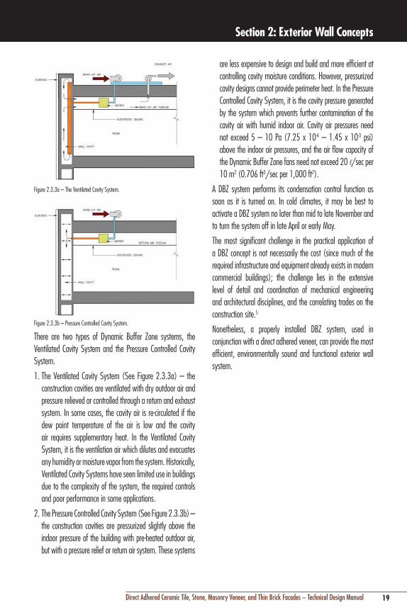
Figure 2.3.3a – The Ventilated Cavity System.
Figure 2.3.3b – Pressure Controlled Cavity System.
There are two types of Dynamic Buffer Zone systems, the Ventilated Cavity System and the Pressure Controlled Cavity System.
1. The Ventilated Cavity System (See Figure 2.3.3a) – the construction cavities are ventilated with dry outdoor air and pressure relieved or controlled through a return and exhaust system. In some cases, the cavity air is re-circulated if the dew point temperature of the air is low and the cavity air requires supplementary heat. In the Ventilated Cavity System, it is the ventilation air which dilutes and evacuates any humidity or moisture vapor from the system. Historically, Ventilated Cavity Systems have seen limited use in buildings due to the complexity of the system, the required controls and poor performance in some applications.
2. The Pressure Controlled Cavity System (See Figure 2.3.3b) – the construction cavities are pressurized slightly above the indoor pressure of the building with pre-heated outdoor air, but with a pressure relief or return air system. These systems
are less expensive to design and build and more efficient at controlling cavity moisture conditions. However, pressurized cavity designs cannot provide perimeter heat. In the Pressure Controlled Cavity System, it is the cavity pressure generated by the system which prevents further contamination of the cavity air with humid indoor air. Cavity air pressures need not exceed 5 – 10 Pa (7.25 x 10⁻⁴ – 1.45 x 10⁻³ psi) above the indoor air pressures, and the air flow capacity of the Dynamic Buffer Zone fans need not exceed 20 l/sec per 10 m2 (0.706 ft3/sec per 1,000 ft2).
A DBZ system performs its condensation control function as soon as it is turned on. In cold climates, it may be best to activate a DBZ system no later than mid to late November and to turn the system off in late April or early May.
The most significant challenge in the practical application of a DBZ concept is not necessarily the cost (since much of the required infrastructure and equipment already exists in modern commercial buildings); the challenge lies in the extensive level of detail and coordination of mechanical engineering and architectural disciplines, and the correlating trades on the construction site.5
Nonetheless, a properly installed DBZ system, used in conjunction with a direct adhered veneer, can provide the most efficient, environmentally sound and functional exterior wall system.

20 Direct Adhered Ceramic Tile, Stone, Masonry Veneer, and Thin Brick Facades – Technical Design Manual
Section 2: Exterior Wall Concepts

Section 3: Types of Direct Adhered Wall Construction
21Direct Adhered Ceramic Tile, Stone, Masonry Veneer, and Thin Brick Facades – Technical Design Manual
Photo: Project-Paragon Prairie Tower, Urbandale, Iowa Designer: David B. Dahlquist, RDG Dahlquist Art Studio, Des Moines, IA Tile Contractor: Des Moines Marble and Mantle Co., Des Moines, IA.Description: Sicis glass mosaic tile installed over pre-cast concrete.

22 Direct Adhered Ceramic Tile, Stone, Masonry Veneer, and Thin Brick Facades – Technical Design Manual
Section 3: Types of Direct Adhered Wall Construction
3.0 ON-SITE CONSTRUCTION3.1 CONCRETE MASONRY UNIT BACK-UP WALLSConcrete block masonry units (CMU) are the preferred back-up wall system for installation of direct adhered cladding in buildings where long service life and maximum durability are desired. CMU wall thickness must be calculated based on engineering analysis as required by building codes. However, the empirical rule of a height/thickness ratio of 18:1, for hollow or partially grouted CMU, remains a good guide for preliminary selection of wall thickness. CMU walls should have a minimum thickness of 8" (200 mm). CMU walls usually require vertical and horizontal reinforcing in order to satisfy seismic requirements. Joint reinforcing should be used at every second horizontal bed joint.
Barrier Concrete Masonry WallsSingle wythe CMU back-up walls are barrier walls and therefore must be waterproofed, even if they are clad with a relatively impermeable cladding. Every joint between the ceramic tile, stone, masonry veneer, or thin brick cladding is a potential source of water penetration. Cement or latex cement leveling plasters (renders) or parge (skim) coats may provide adequate protection in extremely dry climates but water will penetrate during prolonged periods of rain and cause either leakage, deterioration of underlying materials, or sub-surface efflorescence which can result in adhesive bond failure. Through-wall flashing and weep holes can be provided in the CMU at the bottom of the wall and at windows splitting the wall into two thin wythes at the flashing.
Figure 3.1.1 – Typical concrete barrier wall detail with tile or stone installation.
Cavity Concrete Masonry Unit WallsThe outside face of the internal wythe of CMU back-up wall should be damp-proofed, as cavity walls are designed with the anticipation of water penetration. Cavity walls should have an unobstructed air space between the inner and outer wythe. The air space is designed to prevent infiltrated water and vapor from “jumping the gap” to the inner wall, and can be designed to equalize outside and cavity air pressure to prevent water from being driven across the air space. Water can then be collected and directed back to the exterior of the cladding via a cavity weep system (see Section 2 – Pressure Equalization).
The recommended minimum width of a cavity is 2" (50 mm) and should not be greater than 4-1/2" (114 mm) and must be tied with metal ties as required by building codes. If rigid insulation is used in the cavity in cold climates, a 2" (50 mm) air space should be provided from the face of the insulation.
Weep holes should be placed at the bottom of each floor level, bottom of walls, at window sills, and any other locations where flashing is provided. Weep holes are typically spaced at 24" (600 mm), but no greater than 32" (800 mm) on center, and located where the vertical joints of both the CMU and external cladding align. The cavity base should be provided with drainage material, such as gravel or plastic drain fabric to prevent mortar droppings from blocking drainage.

23Direct Adhered Ceramic Tile, Stone, Masonry Veneer, and Thin Brick Facades – Technical Design Manual
Section 3: Types of Direct Adhered Wall Construction
Flashings (see Section 4) are used to collect and direct water which has infiltrated the cavity back to the exterior through weep holes. Flashings must be terminated in a horizontal CMU joint, and must be turned up at the ends of window sills or other horizontal terminations to form a dam, otherwise water will travel laterally and leak at the ends of the flashing. At the face of the external cladding, flashing should be terminated in a rigid sheet metal drip edge to direct any water away from the face of the cladding. If flexible sheet or fluid applied flashings are used, they need to be bonded to a rigid metal drip edge.
Figure 3.1.2 – Typical Cavity Wall Flashing Detail.
The external CMU wythe and external cladding are anchored to the back-up CMU wall with galvanized steel wall ties typically spaced 16" (400 mm) on center vertically and horizontally. Anchors require flexible connections in order to allow for misalignment of the internal/external CMU coursing, and to permit differential movement both within the CMU wall, and between the external cladding – CMU wall and the internal backup wall and structural frame.
Figure 3.1.3 – Typical masonry cavity wall tie systems.
3.2 CLAY (BRICK) MASONRY BACK-UP WALLSClay brick masonry back-up walls, whether designed as barrier or cavity walls, are generally constructed using the same principles and design techniques as concrete masonry back-up walls.
However, there is one important difference between the two materials. Clay brick will expand permanently with age as a result of moisture absorption. When a brick is fired during the manufacturing process, all the moisture has been removed, and clay brick will gradually increase in volume from the original manufactured dimensions (See Section 6.5).
Consequently, clay brick masonry backup walls must make provision for expansion. This is particularly important where clay brick is used in a barrier wall configuration to infill between structural concrete frames; restraint of expansion forces can cause the back-up wall to bow outwards.

24 Direct Adhered Ceramic Tile, Stone, Masonry Veneer, and Thin Brick Facades – Technical Design Manual
Section 3: Types of Direct Adhered Wall Construction
3.3 LIGHT GAUGE STEEL METAL STUD, BACK-UP WALLSLight gauge metal (galvanized steel) framing is commonly used as a back-up wall structure for direct adhered cladding. The metal stud frame can employ a variety of sheathings; the type of sheathing dependent on whether the wall is a barrier wall requiring direct adhesion of the cladding material, or a cavity wall where the sheathing type does not affect adhesion. Metal stud walls can also be used for both pre-fabrication of panels, or, in-situ construction.
Metal stud size and gauge are selected based on known structural properties required to resist live and dead loads. The predominant live load is wind, therefore stiffness usually controls size of metal studs.
Empirical experience has shown that 6" (150 mm) wide, 16 gauge studs spaced 16" (400 mm) on center are appropriate for most applications. However, engineering calculations may show that other widths and gauges are required. Systems, including the framing system and panels, over which tile or stone will be installed shall be in conformance with the International Residential Code (IRC) for residential applications, or applicable building codes. Substrate deflection under all live, dead and impact loads, including concentrated loads, must not exceed L/600 where L=span length. The project should include the intended use and necessary allowances for the expected live load, concentrated load, impact load, and dead load including the weight of the finish and installation materials. While this is the current allowable deflection for metal stud back-up walls, some studies on conventional masonry veneer cavity walls have shown cracking can occur on walls that have significantly less deflection. To date, there have been very few definitive studies conducted on metal stud barrier walls used in direct adhered cladding, but empirical evidence indicates that the composite action of rigid cladding materials, high strength adhesives, and proper specification of sheathing material and attachment method to metal studs does create a more rigid diaphragm compared to a metal stud back-up wall separated by a cavity.
Metal stud framing typically requires lateral bracing to, or integrated within, the structural steel frame of a building. Bracing is dependent on the configuration and unsupported length of the stud frame. Empirical experience has again
proven that integration within the structural steel system not only provides a stiffer metal stud wall by reducing the unbraced lengths of studs, but also improves accuracy and reduces errors by providing an established framework where studs are used as infill, rather than the entire framework.
There are a wide variety of sheathing materials to choose from for metal stud walls, ranging from low cost exterior gypsum sheathing or plywood for cavity wall sheathing, to cement backer board, or lath and cement plaster for barrier walls requiring direct adhesion of the cladding material. In addition, a drainage plane layer can also be integrated into the steel framed barrier wall assembly (typically installed over an exterior rated sheathing) to facilitate the evacuation of moisture from within the wall system.
Gypsum sheathings historically have not been a very durable material for cavity walls, although exterior rated gypsum based sheathings with fiberglass facings and silicone impregnated cores have improved performance. Exterior wall assemblies which incorporate gypsum sheathing require the lath and plaster method for direct adhered cladding systems, as the sheathing composition or facings are not compatible for direct adhesion of exterior veneers (See Figure 3.3.1).
Figure 3.3.1 – Detail showing installation of tile or stone over an exterior gypsum sheathing.
Cement plaster is an ideal sheathing for metal stud back-up walls. This sheathing provides a seamless substrate with no exposed fasteners, resulting in good water and corrosion resistance. The integral reinforcement also provides necessary

25Direct Adhered Ceramic Tile, Stone, Masonry Veneer, and Thin Brick Facades – Technical Design Manual
Section 3: Types of Direct Adhered Wall Construction
stiffness, resistance to shrinkage cracking, and positive imbedded attachment points for anchorage to the metal stud frame. The attachment of reinforcing in cement plaster sheathing and resulting shear and pull-out resistance of the fasteners within the sheathing material is superior to that of pre-fabricated board sheathings such as gypsum or cement backer unit boards (CBU). This factor is important in more extreme climates where there is more significant thermal and moisture movement which can affect sheathings which are poorly fastened or have low shear or pull-out resistance to fasteners.
Cement backer unit boards (CBU), fiber cement underlayment and calcium silicate boards are other choices for metal stud back-up walls requiring direct adhesion of the cladding material. CBU board is pre-fabricated, and provides an efficient, cost effective cementitious substrate for adhesion of cladding materials. While CBU is technically water resistant, it requires waterproofing, as the minimal thickness and corrosion potential of screw attachments increase the possibility for minor cracking, leaks, deterioration, and defects such as efflorescence. Fiber cement underlayments can be sensitive to moisture, and require waterproofing on both sides to resist dimensional instability that may be caused by infiltrated rain water or condensation on the back side of the board. Check with the fiber cement underlayment manufacturer for suitability in exterior configurations.
There are proprietary direct adhered wall systems which employ corrugated steel decking as sheathing and substrate for cladding adhered with special structural silicone adhesives. Because these systems employ spot bonding rather than a continuous layer of adhesive, the combination of open space behind the cladding and the corrugation of the steel decking provides a cavity for drainage and ventilation. This cavity anticipates water penetration, and re-directs water back to the exterior wall surface. However, the underlying metal decking and framing are subject to corrosion facilitated by abrasion of galvanized coatings during construction. Leakage may also occur due to the difficulty of waterproofing the steel and multiple connections/penetrations. Corrugated steel sheathing cavity walls have a limited service life similar to that of barrier walls.
Generally, the light weight and minimal thickness of most sheathing materials for metal stud barrier back-up walls make them more susceptible to differential structural movement and dimensional instability from thermal and moisture exposure. Therefore, careful engineering analysis of cladding-adhesive-sheathing material compatibility, and analysis of the anticipated behavior of the sheathing and its attachment are critically important.
3.4 CAST-IN-PLACE REINFORCED CONCRETE BACK-UP WALLSCast-in-place concrete is one of the most common back-up wall materials for direct adhered external cladding. However, it is unusual that an entire facade back-up wall construction is cast-in-place concrete; typically, only the face of the structure, or walls at the base of a building are concrete. Cast-in-place concrete is only economical for barrier wall construction, and resists water penetration by virtue of mass and density. However, it is still recommended to waterproof concrete, as saturation with water can increase the occurrence of efflorescence.
There are several other important considerations unique to vertically cast-in place concrete used as a back-up wall for external cladding (see Section 5 for detailed information):
n Form release agentsn Surface defectsn Dimensional change and cracking caused by shrinkage
3.5 PRE-CAST CONCRETE WALL PANELS – NEGATIVE AND POSITIVE CAST METHODSCeramic tile, stone, masonry veneer, and thin brick clad pre-cast concrete panels combine durability and tremendous design flexibility with the strength and economy of pre-cast concrete. The primary advantage of this type of backup wall construction is the economy of pre-fabricated, panelized construction. Pre-fabrication permits construction of panels well in advance of the normal sequencing of the on-site construction of a building’s exterior wall. Once the proper stage in the sequence of construction is reached, panels can be erected quickly, without weather or scaffolding erection delays. Pre-cast concrete also allows more stringent quality control afforded by plant production of both the batching and casting of the concrete, as well as the installation of the cladding material.

26 Direct Adhered Ceramic Tile, Stone, Masonry Veneer, and Thin Brick Facades – Technical Design Manual
Section 3: Types of Direct Adhered Wall Construction
† United States Patent No.: 6881768 (and other Patents).
The considerations for clad, pre-cast concrete panels are generally the same as those for panels without an adhered finish, with two exceptions; the method of installation for the cladding material, and investigation of differential thermal and moisture movement between the pre-cast concrete and the cladding material.
Pre-Cast Concrete Panels – Negative and Positive Cast MethodsThere are two methods for installation of cladding on pre-cast concrete panels; the negative and the positive cast methods.
Negative cast panels involve the casting of the concrete and bonding of the cladding in one step. The cladding material is placed face down over the face of the panel mold; joint width and configuration are typically controlled by a grid to insure proper location, uniform jointing and secure fit during the casting operation. Joints are typically cast recessed, and pointed or grouted after the panel is cured and removed from the mold. This method requires the use of a cladding with a dovetail or key-back configuration on the back of the tile (see Figure 3.6.1) in order to provide mechanical locking action between the cladding and the concrete. The mechanical bond strength afforded by the integral locking of the concrete to the back is often augmented by the use of latex portland cement slurry bond coats or polymeric bonding agents just prior to casting of the panel.
Positive cast panels are pre-fabricated in two separate processes. The pre-cast panel is cast, cured, and removed from the mold, and the cladding material is then installed using an adhesive in the production plant. Installation of the cladding after erection and attachment to the structure on-site is viable, but this sequencing minimizes the goal of economy and quality control provided by prefabrication.
Figure 3.5.1 – Negative Cast Method – Tiles are pressed finish face down into molds. Notice the key backed (dove tails) configuration of the tile.
Figure 3.5.2 – Negative Cast Method – Concrete is poured and vibrated over the panels. A slurry bond coat of LATICRETE® 211 Powder mixed with LATICRETE 3701 Mortar Admix can be used as a bonding agent between the tile backs and the concrete pour in this method.
Figure 3.5.3 – Once the tiled panels are curd, the grouting process can begin. These panels are grouted with LATICRETE SpectraLOCK® PRO Grout†.
Figures 3.5.4 – The grouted panels are then stored and allowed to cure before being transported to the job site for installation of the panels.
Pre-Cast Concrete Panels – Differential Movement (Internal to Panel)Differences in the physical characteristics of the pre-cast concrete and the cladding material make this type of back-up construction more susceptible to problems of panel bowing or excessive shear stress at the adhesive interface.

27Direct Adhered Ceramic Tile, Stone, Masonry Veneer, and Thin Brick Facades – Technical Design Manual
Section 3: Types of Direct Adhered Wall Construction
panel is cast, cured and removed from the form for subsequent application of a cladding material in a separate process (positive cast method).
A single skin GFRC panel is the most common type of panel construction. This type of panel typically has a thickness of approximately 1/2" (12 mm). However, it is recommended to increase the thickness of the GFRC panel, to approximately 1" (25 mm) to reduce and better resist differential movement stress. GFRC panels rely on a structural backing or stiffener of a steel stud framework. The steel frame is commonly separated from the GFRC by an air space and attached to the GFRC by means of 1/4" (6 mm) diameter rods called flex anchors, which are imbedded into the GFRC and welded to the framework. These anchors, while rigidly attached, have inherent flexibility determined by diameter and orientation of the rods, which allow some panel movement to accommodate thermal and moisture movement. Heavier panels, or those requiring seismic bracing, also require additional anchors known as gravity or seismic anchors, and are differentiated from flex anchors by their size, configuration, and connection orientation to the GFRC. It is very important to consider the additional weight of the cladding material during the design and engineering of a GFRC panel; you cannot install direct adhered cladding using the positive cast method unless the panel was engineered specifically for that purpose.
Properly engineered and constructed GFRC panels have extremely high strength and good physical characteristics, However, due to the thin section employed in GFRC panels, differential thermal and moisture movement can cause panel bowing, resulting in cracking. Because GFRC panels expand and contract from wet-dry cycling, the adhesion of a cladding can result in a different rate of moisture gain or loss between the front and back of the panel and induce bowing stress. Therefore, careful attention to detailing to prevent rain infiltration and condensation within the wall (see Section 4) are important. Similarly, cladding materials with incompatible coefficients of thermal movement can induce stress. So thermal and moisture movement compatibility with cladding is important, as are low modulus adhesives (flexible/deformable) and movement joints.
Bowing of panels can occur from several mechanisms. In negative cast panels, the concrete shrinks as it hydrates and excess water evaporates. The cladding, being dimensionally stable, is capable of restraining the shrinkage of the concrete. The result is compressive stress in the cladding, and tensile stress at the adhesive interface, with the potential for outward bowing of the cladding surface.
The best technique in preventing panel bowing is to control the concrete shrinkage and to provide the proper ratio of cross-sectional area to stiffness (modulus of elasticity) of the panel. Avoid flat panels less than 5" – 6" (125 – 150 mm) thick; panels as thin as 4" (100 mm) can be used in panels with small areas, or in panels where stiffness is increased by configuration or composite action with a thick cladding material. Concrete mix design and curing conditions can be adjusted to minimize shrinkage.
Several other techniques, such as the amount, location, and type of (pre-stressed) reinforcement, or introduction of camber to the panel, are used to compensate for possible bowing caused by shrinkage.
Differential movement caused by varying coefficients of thermal expansion between the cladding and the concrete can also result in panel bowing. The optimum condition is for the concrete to have a rate of thermal expansion that closely approximates that of the cladding. The thermal coefficient of expansion of concrete can be modified slightly by adjustment of aggregate type, size and proportion to provide compatibility with the cladding and minimize differential movement under temperature changes.
Pre-cast Glass Fiber Reinforced Concrete Wall Panels (GFRC)Pre-cast glass fiber reinforced concrete (GFRC) is the term applied to a material which is fabricated from cement aggregate slurry and reinforced with alkali-resistant glass fibers. Mix composition and types of applications vary, but for installation of direct adhered cladding, GFRC panels consist of a mix which contains 5%, by weight, glass fibers combined with a portland cement/sand slurry which is spray applied onto a form. The form may contain a cladding material (negative cast method) to which a bond coat of latex portland cement is applied just prior to application of the GFRC material, or the

28 Direct Adhered Ceramic Tile, Stone, Masonry Veneer, and Thin Brick Facades – Technical Design Manual
Section 3: Types of Direct Adhered Wall Construction
3.6 LIST OF ARCHITECTURAL DETAILS (See pages 29–77)
n 3.6.1 to 3.6.7 Barrier wall, concrete masonry back-up wall, continuous waterproofing membrane
n 3.6.7 to 3.6.14 Barrier wall, concrete masonry back-up wall, membrane flashing
n 3.6.15 to 3.6.17 Barrier wall, metal stud back-up with cement board or plaster
n 3.6.18 to 3.6.20 Cavity wall, metal stud back-up with cement board or plaster
n 3.6.21 to 3.6.23 Barrier wall, pre-cast concrete panelsn 3.6.24 to 3.6.30 Cavity wall, double-wythe concrete
masonryn 3.6.31 to 3.6.33 Cavity wall, concrete masonry and
metal stud back-up walln 3.6.34 to 3.6.36 Cavity wall, epoxy spot bondingn 3.6.37 to 3.6.39 Barrier wall, GFRC paneln 3.6.40 to 3.6.44 Barrier wall, concrete masonry
back-up wall, continuous waterproofing membrane – LATICRETE® Masonry Veneer Installation System (MVIS™)
n 3.6.45 to 3.6.47 Cavity wall, metal stud back-up with cement board or plaster – LATICRETE MVIS
n 3.6.48 to 3.6.49 Barrier wall, Cavity wall, CMU with metal stud back-up – LATICRETE MVIS
Section 3: Types of Direct Adhered Wall Construction

29Direct Adhered Ceramic Tile, Stone, Masonry Veneer, and Thin Brick Facades – Technical Design Manual
Section 3: Types of Direct Adhered Wall Construction
Figure 3.6.1 – Architectural Detail of Barrier Wall – Concrete masonry unit backup with continuous waterproofing membrane.
30 Direct Adhered Ceramic Tile, Stone, Masonry Veneer, and Thin Brick Facades – Technical Design Manual
Section 3: Types of Direct Adhered Wall Construction
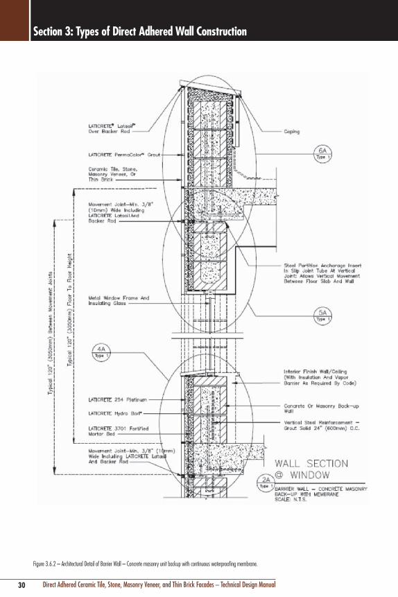
Figure 3.6.2 – Architectural Detail of Barrier Wall – Concrete masonry unit backup with continuous waterproofing membrane.

31Direct Adhered Ceramic Tile, Stone, Masonry Veneer, and Thin Brick Facades – Technical Design Manual
Section 3: Types of Direct Adhered Wall Construction
Figure 3.6.3 – Architectural Details of Barrier Wall – Concrete masonry unit backup with continuous waterproofing membrane.

32 Direct Adhered Ceramic Tile, Stone, Masonry Veneer, and Thin Brick Facades – Technical Design Manual
Section 3: Types of Direct Adhered Wall Construction
Figure 3.6.4 Architectural Details of Barrier Wall – Concrete masonry unit backup with continuous waterproofing membrane.
33Direct Adhered Ceramic Tile, Stone, Masonry Veneer, and Thin Brick Facades – Technical Design Manual
Section 3: Types of Direct Adhered Wall Construction
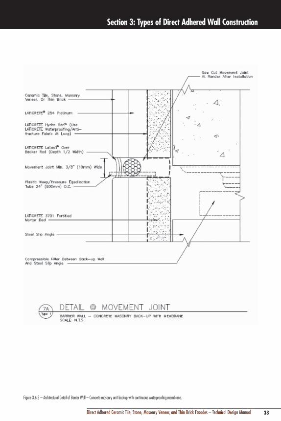
Figure 3.6.5 – Architectural Detail of Barrier Wall – Concrete masonry unit backup with continuous waterproofing membrane.

34 Direct Adhered Ceramic Tile, Stone, Masonry Veneer, and Thin Brick Facades – Technical Design Manual
Section 3: Types of Direct Adhered Wall Construction
Figure 3.6.6 – Architectural Details of Barrier Wall – Concrete masonry unit backup with continuous waterproofing membrane.

35Direct Adhered Ceramic Tile, Stone, Masonry Veneer, and Thin Brick Facades – Technical Design Manual
Section 3: Types of Direct Adhered Wall Construction
Figure 3.6.7 – Architectural Details of Barrier Wall – Concrete masonry unit backup with continuous waterproofing membrane.

36 Direct Adhered Ceramic Tile, Stone, Masonry Veneer, and Thin Brick Facades – Technical Design Manual
Section 3: Types of Direct Adhered Wall Construction
Figure 3.6.8 – Architectural Details of Barrier Wall – Concrete masonry unit backup with membrane flashing.

37Direct Adhered Ceramic Tile, Stone, Masonry Veneer, and Thin Brick Facades – Technical Design Manual
Section 3: Types of Direct Adhered Wall Construction
Figure 3.6.9 – Architectural Details of Barrier Wall – Concrete masonry unit backup with membrane flashing.

38 Direct Adhered Ceramic Tile, Stone, Masonry Veneer, and Thin Brick Facades – Technical Design Manual
Section 3: Types of Direct Adhered Wall Construction
Figure 3.6.10 – Architectural Details of Barrier Wall – Concrete masonry unit backup with membrane flashing.

39Direct Adhered Ceramic Tile, Stone, Masonry Veneer, and Thin Brick Facades – Technical Design Manual
Section 3: Types of Direct Adhered Wall Construction
Figure 3.6.11 – Architectural Details of Barrier Wall – Concrete masonry unit backup with membrane flashing.

40 Direct Adhered Ceramic Tile, Stone, Masonry Veneer, and Thin Brick Facades – Technical Design Manual
Section 3: Types of Direct Adhered Wall Construction
Figure 3.6.12 – Architectural Detail of Barrier Wall – Concrete masonry unit backup with membrane flashing.

41Direct Adhered Ceramic Tile, Stone, Masonry Veneer, and Thin Brick Facades – Technical Design Manual
Section 3: Types of Direct Adhered Wall Construction
Figure 3.6.13 – Architectural Details of Barrier Wall – Concrete masonry unit backup with membrane flashing.

42 Direct Adhered Ceramic Tile, Stone, Masonry Veneer, and Thin Brick Facades – Technical Design Manual
Section 3: Types of Direct Adhered Wall Construction
Figure 3.6.14 – Architectural Details of Barrier Wall – Concrete masonry unit backup with membrane flashing.

43Direct Adhered Ceramic Tile, Stone, Masonry Veneer, and Thin Brick Facades – Technical Design Manual
Section 3: Types of Direct Adhered Wall Construction
Figure 3.6.15 – Architectural Detail of Barrier Wall – Barrier Wall – Light gauge steel (metal stud) with cement backer board (CBU) or cement plaster backup.
44 Direct Adhered Ceramic Tile, Stone, Masonry Veneer, and Thin Brick Facades – Technical Design Manual
Section 3: Types of Direct Adhered Wall Construction
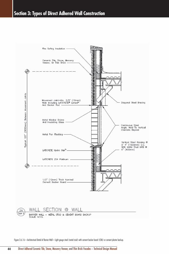
Figure 3.6.16 – Architectural Detail of Barrier Wall – Light gauge steel (metal stud) with cement backer board (CBU) or cement plaster backup.

45Direct Adhered Ceramic Tile, Stone, Masonry Veneer, and Thin Brick Facades – Technical Design Manual
Section 3: Types of Direct Adhered Wall Construction
Figure 3.6.17 – Architectural Details of Barrier Wall – Barrier Wall – Light gauge steel (metal stud) with cement backer board (CBU) or cement plaster backup

46 Direct Adhered Ceramic Tile, Stone, Masonry Veneer, and Thin Brick Facades – Technical Design Manual
Section 3: Types of Direct Adhered Wall Construction
Figure 3.6.18 – Architectural Detail of Cavity Wall – Light gauge steel (metal stud and mortar bed or cement backer board back-up).

47Direct Adhered Ceramic Tile, Stone, Masonry Veneer, and Thin Brick Facades – Technical Design Manual
Section 3: Types of Direct Adhered Wall Construction
Figure 3.6.19 – Architectural Detail of Cavity Wall – Light gauge steel (metal stud and cement board back-up.

48 Direct Adhered Ceramic Tile, Stone, Masonry Veneer, and Thin Brick Facades – Technical Design Manual
Section 3: Types of Direct Adhered Wall Construction
Figure 3.6.20 – Architectural Details of Cavity Wall – Light gauge steel (metal stud and cement board back-up.

49Direct Adhered Ceramic Tile, Stone, Masonry Veneer, and Thin Brick Facades – Technical Design Manual
Section 3: Types of Direct Adhered Wall Construction
Figure 3.6.21 – Architectural Detail of Barrier Wall – Negative cast pre-cast concrete panels.

50 Direct Adhered Ceramic Tile, Stone, Masonry Veneer, and Thin Brick Facades – Technical Design Manual
Section 3: Types of Direct Adhered Wall Construction
Figure 3.6.22 – Architectural Detail of Barrier Wall – Negative cast pre-cast concrete panels.

51Direct Adhered Ceramic Tile, Stone, Masonry Veneer, and Thin Brick Facades – Technical Design Manual
Section 3: Types of Direct Adhered Wall Construction
Figure 3.6.23 – Architectural Detail of Barrier Wall – Negative cast pre-cast concrete panels.

52 Direct Adhered Ceramic Tile, Stone, Masonry Veneer, and Thin Brick Facades – Technical Design Manual
Section 3: Types of Direct Adhered Wall Construction
Figure 3.6.24 – Architectural Detail of Cavity Wall – Concrete masonry back-up.

53Direct Adhered Ceramic Tile, Stone, Masonry Veneer, and Thin Brick Facades – Technical Design Manual
Section 3: Types of Direct Adhered Wall Construction
Figure 3.6.25 – Architectural Detail of Cavity Wall – Concrete masonry back-up.

54 Direct Adhered Ceramic Tile, Stone, Masonry Veneer, and Thin Brick Facades – Technical Design Manual
Section 3: Types of Direct Adhered Wall Construction
Figure 3.6.26 – Architectural Details of Cavity Wall – Concrete masonry back-up.

55Direct Adhered Ceramic Tile, Stone, Masonry Veneer, and Thin Brick Facades – Technical Design Manual
Section 3: Types of Direct Adhered Wall Construction
Figure 3.6.27 – Architectural Details of Cavity Wall – Concrete masonry back-up.

56 Direct Adhered Ceramic Tile, Stone, Masonry Veneer, and Thin Brick Facades – Technical Design Manual
Section 3: Types of Direct Adhered Wall Construction
Figure 3.6.28 – Architectural Detail of Cavity Wall – Concrete masonry back-up.

57Direct Adhered Ceramic Tile, Stone, Masonry Veneer, and Thin Brick Facades – Technical Design Manual
Section 3: Types of Direct Adhered Wall Construction
Figure 3.6.29 – Architectural Details of Cavity Wall – Concrete masonry back-up.

58 Direct Adhered Ceramic Tile, Stone, Masonry Veneer, and Thin Brick Facades – Technical Design Manual
Section 3: Types of Direct Adhered Wall Construction
Figure 3.6.30 – Architectural Details of Cavity Wall – Concrete masonry back-up.

59Direct Adhered Ceramic Tile, Stone, Masonry Veneer, and Thin Brick Facades – Technical Design Manual
Section 3: Types of Direct Adhered Wall Construction
Figure 3.6.31 – Architectural Detail of Cavity Wall – Concrete masonry unit with steel stud backup.

60 Direct Adhered Ceramic Tile, Stone, Masonry Veneer, and Thin Brick Facades – Technical Design Manual
Section 3: Types of Direct Adhered Wall Construction
Figure 3.6.32 – Architectural Detail of Cavity Wall – Concrete masonry unit with steel stud backup.
61Direct Adhered Ceramic Tile, Stone, Masonry Veneer, and Thin Brick Facades – Technical Design Manual
Section 3: Types of Direct Adhered Wall Construction
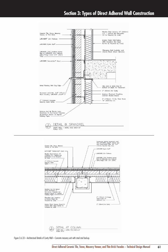
Figure 3.6.33 – Architectural Details of Cavity Wall – Concrete masonry unit with steel stud backup.
62 Direct Adhered Ceramic Tile, Stone, Masonry Veneer, and Thin Brick Facades – Technical Design Manual
Section 3: Types of Direct Adhered Wall Construction
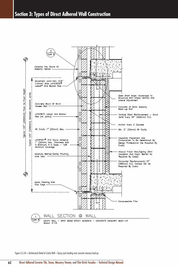
Figure 3.6.34 – Architectural Detail of Cavity Wall – Epoxy spot bonding over concrete masonry back-up.

63Direct Adhered Ceramic Tile, Stone, Masonry Veneer, and Thin Brick Facades – Technical Design Manual
Section 3: Types of Direct Adhered Wall Construction
Figure 3.6.35 – Architectural Detail of Cavity Wall – Epoxy spot bonding over concrete masonry back-up0

64 Direct Adhered Ceramic Tile, Stone, Masonry Veneer, and Thin Brick Facades – Technical Design Manual
Section 3: Types of Direct Adhered Wall Construction
Figure 3.6.36 – Architectural Details of Cavity Wall – Epoxy spot bonding over concrete masonry back-up

65Direct Adhered Ceramic Tile, Stone, Masonry Veneer, and Thin Brick Facades – Technical Design Manual
Section 3: Types of Direct Adhered Wall Construction
Figure 3.6.37 – Architectural Detail of Barrier Wall – GFRC pre-cast concrete panels - negative cast method.

66 Direct Adhered Ceramic Tile, Stone, Masonry Veneer, and Thin Brick Facades – Technical Design Manual
Section 3: Types of Direct Adhered Wall Construction
Figure 3.6.38 – Architectural Detail of Barrier Wall – GFRC pre-cast concrete panels – negative cast method.

67Direct Adhered Ceramic Tile, Stone, Masonry Veneer, and Thin Brick Facades – Technical Design Manual
Section 3: Types of Direct Adhered Wall Construction
Figure 3.6.39 – Architectural Details of Barrier Wall – GFRC pre-cast concrete panels – negative cast method.
68 Direct Adhered Ceramic Tile, Stone, Masonry Veneer, and Thin Brick Facades – Technical Design Manual
Section 3: Types of Direct Adhered Wall Construction
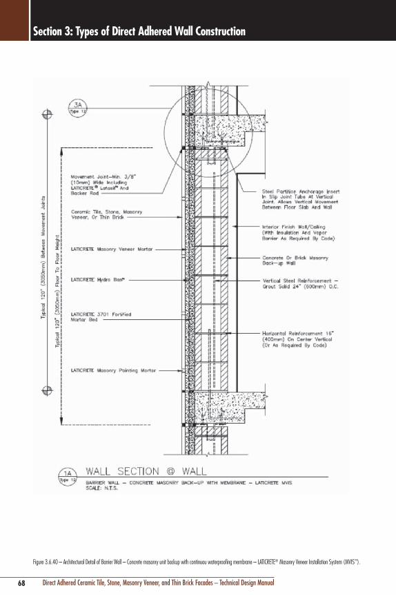
Figure 3.6.40 – Architectural Detail of Barrier Wall – Concrete masonry unit backup with continuou waterproofing membrane – LATICRETE® Masonry Veneer Installation System (MVIS™).

69Direct Adhered Ceramic Tile, Stone, Masonry Veneer, and Thin Brick Facades – Technical Design Manual
Section 3: Types of Direct Adhered Wall Construction
Figure 3.6.41 – Architectural Detail of Barrier Wall – Concrete masonry unit backup with continuous waterproofing membrane – LATICRETE MVIS.

70 Direct Adhered Ceramic Tile, Stone, Masonry Veneer, and Thin Brick Facades – Technical Design Manual
Section 3: Types of Direct Adhered Wall Construction
Figure 3.6.42 – Architectural Details of Barrier Wall – Concrete masonry unit backup with continuous waterproofing membrane – LATICRETE® MVIS™.
71Direct Adhered Ceramic Tile, Stone, Masonry Veneer, and Thin Brick Facades – Technical Design Manual
Section 3: Types of Direct Adhered Wall Construction
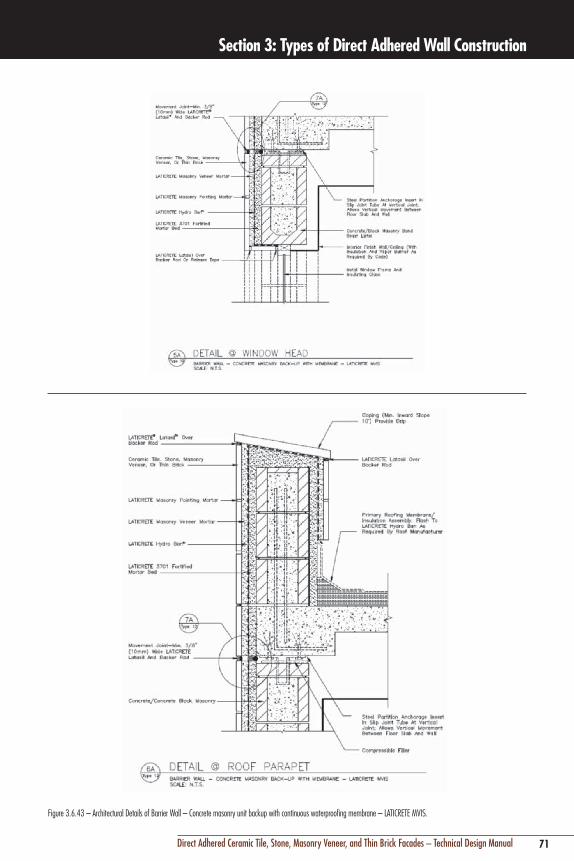
Figure 3.6.43 – Architectural Details of Barrier Wall – Concrete masonry unit backup with continuous waterproofing membrane – LATICRETE MVIS.

72 Direct Adhered Ceramic Tile, Stone, Masonry Veneer, and Thin Brick Facades – Technical Design Manual
Section 3: Types of Direct Adhered Wall Construction
Figure 3.6.44 – Architectural Detail of Barrier Wall – Concrete masonry unit backup with continuous waterproofing membrane – LATICRETE® MVIS™.

73Direct Adhered Ceramic Tile, Stone, Masonry Veneer, and Thin Brick Facades – Technical Design Manual
Section 3: Types of Direct Adhered Wall Construction
Figure 3.6.45 – Architectural Detail of Cavity Wall -– Light gauge steel (metal stud and mortar bed or cement backer board back-up) – LATICRETE MVIS.

74 Direct Adhered Ceramic Tile, Stone, Masonry Veneer, and Thin Brick Facades – Technical Design Manual
Section 3: Types of Direct Adhered Wall Construction
Figure 3.6.46 – Architectural Detail of Cavity Wall – Light gauge steel (metal stud and mortar bed or cement backer board back-up) – LATICRETE® MVIS™.

75Direct Adhered Ceramic Tile, Stone, Masonry Veneer, and Thin Brick Facades – Technical Design Manual
Section 3: Types of Direct Adhered Wall Construction
3.6.47 – Architectural Details of Cavity Wall -- Light gauge steel (metal stud and mortar bed or cement backer board back-up) – LATICRETE MVIS.

76 Direct Adhered Ceramic Tile, Stone, Masonry Veneer, and Thin Brick Facades – Technical Design Manual
Section 3: Types of Direct Adhered Wall Construction
Figure 3.6.48 – Architectural Detail of Cavity Wall -- Light gauge steel (metal stud and mortar bed or cement backer board back-up) – LATICRETE® MVIS™.
77Direct Adhered Ceramic Tile, Stone, Masonry Veneer, and Thin Brick Facades – Technical Design Manual
Section 3: Types of Direct Adhered Wall Construction
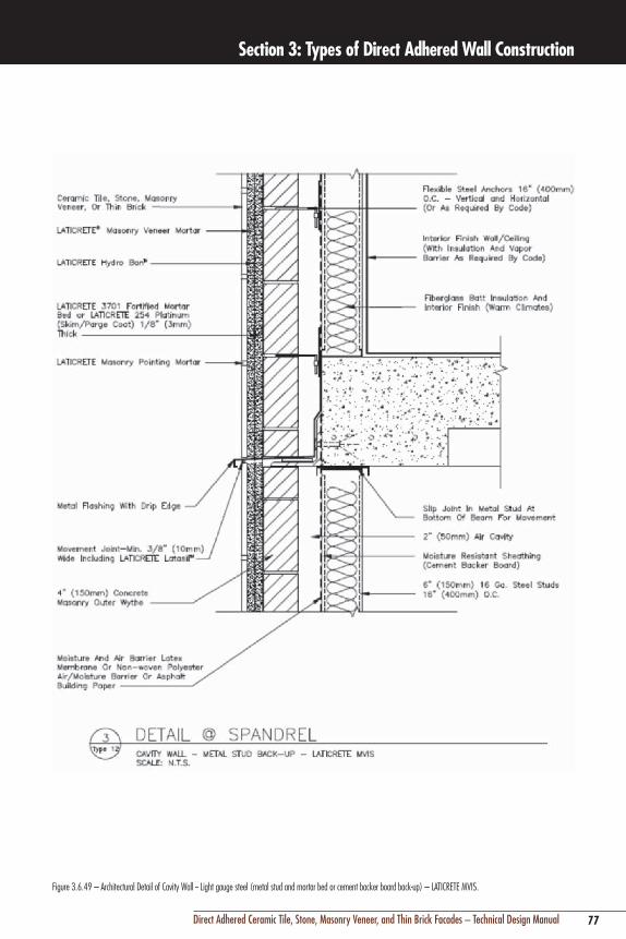
Figure 3.6.49 – Architectural Detail of Cavity Wall -- Light gauge steel (metal stud and mortar bed or cement backer board back-up) – LATICRETE MVIS.

78 Direct Adhered Ceramic Tile, Stone, Masonry Veneer, and Thin Brick Facades – Technical Design Manual
Section 3: Types of Direct Adhered Wall Construction
3.7 CASE STUDY – CERAMIC TILE CLAD PRE-CAST CONCRETESaskatoon City Hospital, winner of the prestigious PCI Design Award, has received a great deal of praise for the appearance and technical superiority of its pre-cast concrete wall system. The pre-cast panels are clad with ceramic tile, a first in Saskatoon, Saskatchewan, Canada. They also feature the proven “rain-screen” principle. “The detailing of the pre-cast cladding material is very well handled. Some tough challenges were overcome in this rather sophisticated panel system”, said the Pre-cast/Pre-stressed Concrete Institute judges when they presented the award to the hospital’s architects.
The ProjectThe 492-bed facility provides a community general hospital for Saskatoon, and a major referral center for all of northern Saskatchewan.
In choosing pre-cast wall panels, the design team was seeking a high performance wall with an effective and durable air barrier, high insulation value and minimal thermal breaks. They wanted factory manufacturing of the system to obtain superior quality and rapid enclosure of the hospital during construction. This type of high quality wall system is suitable for all buildings, but particularly those with high humidity in severe climates.
TestimonialThe hospital wall is a pre-cast concrete sandwich panel incorporating insulation and a rain screen, with a ceramic tile finish on the exterior. This is how a high-performance wall was described in a report by City Hospital Architects Group:
“Technically, a quality wall has an exterior skin which can expand and contract in various conditions. Behind this skin is an air space which is maintained at exterior air pressures (positive and negative), consequently excluding water penetration through the façade due to air pressure differentials. This technique is commonly referred to as a rain screen. The next element adjacent to the air space is insulation which, in addition to its envelope function, protects the building structure and any structure supporting the outer skin, from thermal stresses. An air/vapor barrier can be applied on either side of the system supporting the outer skin (or be within the
system). The connections between the outer skin and the inner supporting structure should be minimal. Connections between the total wall system and the building should not pierce the air/vapor barrier and should be thermally protected.”
Figure 3.7.1 – Saskatoon City Hospital – Ceramic tile clad pre-cast concrete panels.
Figure 3.7.2 – Saskatoon City Hospital – Ceramic tile clad pre-cast concrete panels.
Figure 3.7.3 Wall Sections – Saskatoon City Hospital – ceramic tile clad pre-cast concrete panels with pressure-equalized rain-screen cavity.

79Direct Adhered Ceramic Tile, Stone, Masonry Veneer, and Thin Brick Facades – Technical Design Manual
Section 4: Structural and Architectural Considerations
79Direct Adhered Ceramic Tile, Stone, Masonry Veneer, and Thin Brick Facades – Technical Design Manual
Photo: Project-Biogen Idec, San Diego, CA 2005, Architect: HOK, Culver City, CA; Stone Contractor: Klaser Tile, Chula Vista, CA.Description: Indian sandstone veneer over cement render over steel framing and exterior rated sheathing.

80 Direct Adhered Ceramic Tile, Stone, Masonry Veneer, and Thin Brick Facades – Technical Design Manual
Section 4: Structural and Architectural Considerations
4.0 GENERAL BACKGROUNDImportant structural and architectural considerations in the design of direct adhered cladding are:
n Compatibility of the bonding adhesive with both the cladding material and the substrate
n Dimensional stability of the cladding material and substrate
n Thermal and moisture expansion compatibility between the cladding material and the substrate
n Differential movement capability of bonding adhesive (deformability)
Figure 4.1.1 – Types of structural movement.
4.1 TYPES OF STRUCTURAL MOVEMENTThe structural frames of modern buildings are considerably more vulnerable to movement than traditional massive masonry or concrete structures. This increasing use of framed construction is not only dictated by economics, but also the development of new materials and methods which are stronger, lighter, and more capable of spanning great distances and heights.
While modern structural frames are safe, they are designed to be more flexible and typically provide less resistance to movement. It is essential that direct adhered external cladding be designed and constructed to accommodate all types of structural movement. Direct adhered external cladding differs from mechanically anchored cladding primarily because structural movement can be transmitted through the direct adhesive connection, accumulate, and then exert stress on the
cladding, which can result in cracking, buckling, or crushing of the cladding or other wall components.
Most of the structural movement in a direct adhered facade is controlled by the underlying wall components and their connection to the building’s structural frame. The adhered cladding is a non-structural finish. However, both the adhesive and the perimeter interfaces with the cladding must be designed to further control and minimize reflection of differential structural movement.
The most difficult aspect of designing an exterior wall system is that structural movement is somewhat unpredictable and indeterminable. Building movements are individually quantifiable through mathematical calculations; however, building movements are dynamic, constantly changing and not necessarily simultaneous. As a result, the exact magnitude of resulting stresses from building movement can be difficult to predict. Fortunately, the structural theories used in most building codes dictate the use of “worst case” conditions; movements are considered to act simultaneously, and be of the highest possible magnitude in order to provide a safety factor for the most extreme conditions.
Types of Structural Movementn Live loads (wind, seismic) and dead loads (gravity)n Thermal movementn Drying shrinkage*n Moisture expansion*n Elastic deformation under initial loadsn Creep of concrete under sustained load*n Differential settlement
*Denotes types of movement in concrete or wood structural frames only.
LoadsForces cayse by gravity, wind or seismic loads must be analyzed to determine the required tensile and shear bond strength of adhesive mortars to resist these forces.
For non-load bearing curtain walls, wind loading is typically the dominant structural load which a wall must be engineered to resist. The wall must be engineered to have not only sufficient strength to resist the positive and negative (suction) wind pressures, but also sufficient stiffness so that the direct adhered cladding material does not crack under high wind loads. Deflection or stiffness of back-up wall construction

81Direct Adhered Ceramic Tile, Stone, Masonry Veneer, and Thin Brick Facades – Technical Design Manual
Section 4: Structural and Architectural Considerations
should be limited to 1/600 of the unsupported span of the wall under wind loads.
In regions with seismic activity, the shearing force exerted by seismic activity is by far the most extreme force that an adhesive bond must be able to withstand. The shear stress exerted by an earthquake of a magnitude of 7 on the Richter Scale is approximately 215 psi (1.5 MPa), so this value is considered the minimum safe shear bond strength of the cladding, adhesive and substrate interfaces.
The shearing forces induced by thermal movement are similar to seismic activity in that they are typically far greater than the dead load (weight) of the cladding material.
Wind and seismic forces can also cause lateral building movement called drift. This type of movement is characterized by the swaying of a building from wind or seismic activity, and is the type of movement that can typically be controlled and isolated with movement joints. While movement joints are typically a structural engineering function of the underlying structure and back-up wall construction, it is critical that this movement capability extend through to the leveling and adhesive mortars, as well as to the external cladding surface and interfaces with other wall components.
Building codes typically limit drift or displacement of a story relative to the adjacent story to 0.005 times the story height. For example, a 12' (4 m) single story height could have maximum allowable drift due to design wind load of 0.005 x 12' (4 m) x 12 in/ft (1000 mm/m) = 0.72" (18 mm) between stories (movement is not cumulative, but relative only between each floor level). This is significant movement, although under worst case conditions. Placement of movement joints horizontally at each floor level, and vertically at strategic locations such as along column or window edges every 8' – 12' (2.4 – 3.7 m) maximum is mandatory to isolate wall components and minimize or eliminate restraint of drift. The use of a low modulus or flexible adhesive (e.g. LATICRETE® 254 Platinum) is also critical in accommodating structural drift movement (see Section 7 – Adhesive Criteria). Building serviceability factor, as defined by Section 12.12.1 of American Society of Civil Engineers (ASCE) 7 or local building code, determines the allowable amount of drift for seismic and wind displacement. If the serviceability limits of a structure
exceed the design serviceability limits then the building may no longer be considered useful, even when it is structurally sound.
In severe seismic or wind zones, the effects of structural drift on direct adhered cladding can be further minimized by isolating the underlying substrate with a cleavage membrane and applying a leveling mortar over galvanized steel reinforcing wire fabric attached with flexible connections to the underlying support wall or structure. The cleavage membrane prevents partial bond and allows the cement leveling mortar substrate to “float” over the underlying back-up wall and provide isolation from transmission of structural movement by flexible structural connections to the wire reinforcing (See Figure 4.1.2).
Figure 4.1.2 – Detail ES-W201(E).
Thermal MovementAll building materials expand and contract when exposed to changes in temperature. There are two factors to consider in analyzing thermal movement:
n The rates of expansion of different materials (also known as the linear coefficient of thermal expansion)
n The anticipated temperature range exposure
The primary goal in analyzing thermal movement is to determine both the cumulative and individual differential movement that occurs within and between components of the facade wall assembly.
For example, a porcelain tile has an average coefficient of linear expansion of between 4 – 8 x 10⁻⁶ mm/°C/mm of length. Concrete has an expansion rate of 5 x 10⁻⁶ in/in/°F (9 – 10 x 10-6 mm/°C/mm). The surface temperature of

82 Direct Adhered Ceramic Tile, Stone, Masonry Veneer, and Thin Brick Facades – Technical Design Manual
Section 4: Structural and Architectural Considerations
a tile or stone may reach as high as 160°F (71°C) in hot sun, and the lowest ambient temperature in a moderately cold climate may be 14°F (-10°C), resulting in a temperature range of 146°F (81°C) for the tile. The temperature range of the concrete structure, not exposed directly to the sun and insulated from temperature extremes by the tile, and leveling/adhesive mortars as well as length of exposure, may only be 30°C. For a 50 m (164') wide building, the differential movement is as follows:
Concrete 0.000010 x 50 m x 1000 mm x 30°C
= 15 mm
Tile 0.000006 x 50 m x 1000 mm x 81°C
= 24.3 mm
Because the tile thermal expansion is greater, this figure is used. The general rule for determining the width of a movement joint is 2 – 3 times the anticipated movement, or 3 x 24.3 mm (0.96 in) = 73 mm (2.9"). The minimum recommended width of any individual joint is 3/8" (10 mm). Therefore, a minimum of 8 vertical joints (inclusive of corners) across a 164' (50 m) wide facade, each 3/8" (10 mm) in width is required just to control thermal movement under the most extreme conditions. Similarly, there is an approximate potential differential movement of 9.3 mm (3/8") over 50 m (164') between the veneer and underlying concrete structure that must be accommodated by the flexibility of the adhesive and leveling mortars.
Thermal induced structural deflectionThermal induced structural deflection, or bending of the building’s structural frame, is another often overlooked cause of stress on a direct adhered facade. This phenomena can occur when there is a significant temperature differential between the exterior and interior of the structural frame, causing the frame to bend and exert force on the exterior wall assembly. For example, a 100°F (38°C) temperature differential between the interior and exterior structural steel or concrete members in an extremely hot climate with an air-conditioned interior can result in a change of length of 7/8" (22 mm) over a 100' (30.5 m) distance. An engineering analysis to determine movement joint requirements is mandatory, because, unlike a mechanically anchored wall finish with flexible connections, the frame transmits movement directly to the fixed, direct adhered cladding. This problem is more acute in steel framed
buildings.
Linear Thermal Movement of Different Porcelain Ceramic Tile Sizes
Tile Size Thermal Coefficient x Temp. Range x Tile Length
Linear Movement per Tile in mm
24" x 24" (600 x 600 mm)
(8 x 10⁻⁶) (60°C) (600 mm)
0.288 mm
16" x 16" (400 x 400 mm)
(8 x 10⁻⁶) (60°C) (400 mm)
0.192 mm
12" x 12" (300 x 300 mm)
(8 x 10⁻⁶) (60°C) (300 mm)
0.144 mm
8" x 8" (200 x 200 mm)
(8 x 10⁻⁶) (60°C) (200 mm)
0.096 mm
6" x 6" (150 x 150 mm)
(8 x 10⁻⁶) (60°C) (150 mm)
0.072 mm
4" x 4" (100 x 100 mm)
(8 x 10⁻⁶) (60°C) (100 mm)
0.048 mm
Figure 4.1.3 – Linear thermal movement of different porcelain ceramic tile sizes at normal maximum temperature range for temperate climate.
Moisture Shrinkage/ExpansionUnderlying structures or infill walls constructed of concrete or concrete masonry will undergo permanent shrinkage from cement hydration and loss of water after initial installation. The amount of shrinkage is dependent on several variables; water/cement ratio of concrete, relative humidity/rain fall, thickness of concrete, and percentage of steel reinforcement. While an average of 50% of ultimate shrinkage occurs within the first 3 – 6 months (depending on weather conditions), the remainder can occur over a period of 2 or more years. In a wet, humid environment, the period of high initial shrinkage is difficult to predict. If possible, it is recommended to sequence or delay the direct application of cladding and leveling mortars until after the majority of shrinkage of a concrete structure has occurred, which under ideal conditions may be about 6 months. If scheduling and sequencing does not permit a 6 month wait, it is recommended to wait a minimum of 45 – 90 days after the placement of structural concrete, depending on humidity and drying/curing conditions, before installation of cladding or cement leveling mortars. In some countries, such as Germany, there are building regulations which require a minimum 6 month waiting period.
The reason for the waiting period is that the amount and rate of shrinkage of the concrete is greatest during the first 6 month period, and there is no sense exposing the adhesive interface to differential movement stress if it can be avoided,

83Direct Adhered Ceramic Tile, Stone, Masonry Veneer, and Thin Brick Facades – Technical Design Manual
Section 4: Structural and Architectural Considerations
as the cladding will not shrink, and leveling mortars will have a significantly lower amount and rate of shrinkage. Also, the concrete will reach its ultimate compressive and tensile strength within 28 days, and be much more resistant to cracking after that period.
As an example, reinforced concrete walls will ultimately shrink between 0.00025 – 0.001 times the length (0.025 – 0.10%), depending on a number of variables such as water/cement ratio or the amount of steel reinforcing. A concrete framed building which is 120' (40 m) high can shrink up to 3/4" (19 mm) vertically. Cladding will not shrink, and in some cases will undergo moisture expansion (see Section 6 – Thin Brick). As a result, there must be provision in the movement joints to absorb at least 3/4" (19 mm) of contraction (joint width must be approximately 2 – 3 times the anticipated movement, or 2-1/4" (57 mm) total. Assuming 10 stories, at 12' (4 m) height for each story, shrinkage could add approximately 1/4" (6 mm) in width to the horizontal movement joint at each floor level, depending on how much of the ultimate shrinkage has occurred at the time of installation of the cladding.
Conversely, ceramic tile and thin brick cladding, as well as underlying clay brick masonry back-up walls, can undergo long term, permanent expansion from moisture absorption. Dimensional changes in ceramic tile can be virtually eliminated by use of an impervious or semi-vitreous tile. However, thin or thick clay brick masonry must be detailed with proper movement joints to accommodate moisture expansion. (See Section 6.5 – Thin Brick)
Structural DeformationAs a building is constructed, the weight of materials increase, and permanent movement, known as elastic deformation, occurs in heavily stressed components of the structure. For example, the spandrel beam or lintel over the windows is allowed to move or deflect up to 1/500 of the span. Therefore, a beam spanning 15' (4.6 m) between columns is allowed to move approximately 3/8" (10 mm) vertically from initial position under full load. The spandrel beam is typically the optimum location for a horizontal movement joint at each floor level of a building. The joint should continue from the surface of the cladding and through the adhesive and leveling mortars. Similarly, it is also critical to leave a space between the bottom
of the spandrel beam and the top of the backup masonry wall to allow for this movement. The backup wall is not designed as a load bearing wall, and may crack or bulge when directly exposed to loads from the floor above. This space between each floor is typically filled with a compressible filler to allow for movement, flashed and sealed to prevent water and air penetration. The backup wall should be braced laterally to the columns with masonry anchors and reinforcing.
Deformation movement in concrete structures, also known as creep, occurs more slowly and can increase initial deflections by 2 – 3 times. Allowance for this type of long term movement must be considered in the design of movement joints. Creep is typically of greater concern in taller, reinforced concrete frame buildings, especially those that do not incorporate compressive reinforcing steel in the structural design.
Example:
A typical 10 story building is 130' (40 m) tall. Creep, or long term deformation, may be as high as 0.065% of the height. Creep would be calculated as follows: 40 m x 1000 mm x 0.00065 = 1" (25 mm) potential reduction in the height of the concrete structure.
Differential SettlementBuildings structures are typically designed to allow for a certain tolerance of movement in the foundation known as differential settlement. In most buildings, the effect of normal differential settlement movement on the exterior wall assembly is considered insignificant, because significant dead loading and allowable settlement has occurred long before application of the cladding. Differential settlement of a building’s foundation that occurs beyond acceptable tolerances is considered a structural defect, with significant consequences to a direct adhered ceramic tile facade.

84 Direct Adhered Ceramic Tile, Stone, Masonry Veneer, and Thin Brick Facades – Technical Design Manual
Section 4: Structural and Architectural Considerations
Thermal Coefficient of Expansion of Concrete Depending on Aggregate Type
Aggregate Type Coefficient of Expansion, millionths (10 – 6)
(from one source) per degree Fahrenheit per degree Celsius
Quartz 6.6 11.9
Sandstone 6.5 11.7
Gravel 6.0 10.8
Granite 5.3 9.5
Basalt 4.8 8.6
Limestone 3.8 6.8NOTE: Coeffiecients of concrete made with aggregates from different sources may vary widely from these stated values, especially those for gravels, granite and limestone. The coeffiecient for structural lightweight concrete varies from 3.9 – 6.1 millionths (10-6) per degree Fahrenheit (7 to 11 millionths per degree Celsius) depending on the aggregate type and amount of natural sand.Figure 4.1.4 – Control of concrete thermal movement by type of aggregate.
4.2 ARCHITECTURAL CONSIDERATIONSThis section examines the architectural practices that contribute to the successful performance of a direct adhered facade. Exterior walls are complex assemblies containing many materials and systems that must interface, and the performance of the interface between components is as important as the individual components’ performance.
Windows, Glazing, and Window Maintenance SystemsIn addition to satisfying obvious needs to provide interior daylight and exterior views, windows function in many of the same ways as the other components of an exterior wall assembly. Windows control heat flow and air infiltration, provide resistance to water and air pressures, sound attenuation, as well as an aesthetically pleasing facade.
While the functional and aesthetic criteria for selection and design of windows is beyond the scope of this manual, it is important to consider the window’s interface with the direct adhered external cladding system.
Window Interface Requirementsn Configuration and location of windowsn Mechanical connection of the window frame (wall
assembly or structure)n Compatibility of materialsn Water and air infiltration resistancen Flashing and drainage of infiltrated water (internal and
external to window)n Maintenance (window washing systems)
Configuration and LocationThe configuration and arrangement of windows can minimize water infiltration and maximize structural performance, which in turn can have significant impact on the performance of direct adhered cladding. Configuration refers to whether windows are designed as punched openings, horizontal ribbons, or large glass assemblies. Location refers to the position in the wall; the window can range from located flush with the external cladding to recessed or protected by overhangs and projections.
Configuration primarily affects structural performance. Horizontal ribbons or large areas of windows create a discontinuity of the structural back-up wall or frame for the direct adhered cladding. As a result, it is not only more difficult to provide proper structural bracing and stiffness, but there may also be greater wind, seismic and gravity loads that may be transferred from the windows to the back-up wall or structural frame.
Location of the window can have a significant effect on the control of water infiltration. A window flush to the external cladding allows water that is shed by the external cladding to penetrate openings in sealant joints or improperly flashed cavities. Water penetration behind external cladding that is encouraged by the combination of flush window placement and poor sealant/flashing is one of the leading causes of efflorescence and freeze-thaw problems in direct adhered facades.
Flush windows are also exposed to rain runoff from the cladding system which may contain alkalis from cementitious materials used in the installation of the cladding. The alkalis can etch window glass and corrode metal window frames and glazing materials. Recessed windows can present the same problems if the horizontal sill is not properly sloped away from the window frame to shed water, and not properly flashed or waterproofed to recognize the potential for water penetration on a horizontal surface.
Mechanical ConnectionsWindow frames are designed to transfer external wind loads, air pressure differentials and thermal loads to the backup structure. The mechanical connections of windows must be detailed and installed in a manner so as not to impart stress on the adhesive bond or the integrity of the cladding. Connection must also avoid penetration of flashings and waterproofing
85Direct Adhered Ceramic Tile, Stone, Masonry Veneer, and Thin Brick Facades – Technical Design Manual
Section 4: Structural and Architectural Considerations
allows rain water, sheeting down over the cladding surface, to drip down and away from window glass. Even more critical is for internal wall flashings to have a drip edge of rigid metal to allow any alkaline water drained from internal cavities or joints to drip beyond both the surface of the cladding as well as the window glass. It is also good practice that window glass be washed periodically during construction, and immediately after completion, until high alkaline content in some of the building materials is reduced or eliminated by encapsulation in the wall assembly. Glass, metal frames, and other components of a wall system can be also damaged by dilute phosphoric or hydrofluoric acids that may be used in cleaning cementitious residue from cladding surfaces.
Water and Air InfiltrationWindows must be designed to anticipate some water infiltration both through the frame, and between the glass and the frame. Water will infiltrate either from rain, moisture driven by air pressure differentials, or from internal or external condensation. However, water should never penetrate beyond the inner window plane in accordance with American Society for Testing and Materials (ASTM) E331 “Standard Test Method for Water Penetration of Exterior Windows, Skylights, Doors, and Curtain Walls by Uniform Static Air Pressure Difference.” The window should have an internal drainage and weep channel that prevents normal water penetration from escaping into and behind the wall assembly.
While air infiltration through windows has obvious effects on control of heat flow and pollutants, the primary concern in direct adhered cladding systems is the flow of moisture laden interior or exterior air, which can condense within internal cavities between the window and the wall system.
Window Maintenance SystemsWindow washing systems may be required to be integrated into the surface of a direct adhered cladding system. Integral systems consist of either metal tracks which are recessed below the cladding, or “button” guides which protrude from the surface which engage a metal track attached to the maintenance platform. The connection of these systems must be made to the underlying structure, and direct adhered veneer installations must be isolated from these track systems.
membranes to prevent water infiltration; any penetrations must be protected with sealant. Window frame attachments must not pass through or be anchored directly to the cladding, and window frames should be isolated from the cladding by flexible sealants and be directly attached only to underlying structural components. The glass industry has comparable guidelines that require the window glazing system to isolate the glass from stress that may be induced by the window frame or other parts of the exterior wall assembly with flexible glazing materials, such as rubber gaskets or sealants, and neoprene setting blocks.
Compatibility of MaterialsIt is important to consider the compatibility of window frames and other window components such as plastics and rubber with the materials employed in a direct adhered wall system. Consider first that cement mortars, adhesives and grouts can have a corrosive effect on aluminum and glass. Aluminum must be separated from contact with cementitious materials by materials chemically inert to aluminum.
Similarly, galvanic corrosion from moisture penetrating protective finishes, or from reaction of two different connecting metals in contact with moisture, can corrode window frames or critical components of the direct adhered cladding, such as metal stud frames and screw/bolt connections.
Alkali and Acid AttackMaterials commonly used in direct adhered cladding can cause surface damage to glass in windows, and to a lesser degree to metal frames. Cementitious adhesives, grouts, and underlying substrates such as cement board, concrete masonry, or pre-cast concrete contain free alkaline minerals. Alkalis can be leached from these materials and stain or etch glass if allowed to remain on the surface for a few days. The alkaline solution attacks the glass surface by dissolving away surface ingredients (sodium) which results in haziness and roughness. When this occurs, there is no practical way of restoring the glass surface.
The location of the windows in the wall assembly, and the detailing and configuration of the cladding surface become critically important if alkali attack is to be avoided. Window glass should always be set back and not flush with the cladding surface. The head of the window recess should also be configured to contain a recessed drip edge. This design

86 Direct Adhered Ceramic Tile, Stone, Masonry Veneer, and Thin Brick Facades – Technical Design Manual
Section 4: Structural and Architectural Considerations
Rigid wall insulation is commonly a glass or plastic material that is made into a foam by mixing with air, carbon dioxide, fluorocarbons and other gases. The gases are trapped and form insulating air cells which can comprise of up to 90% of the material. Polystyrene, polyurethane, polyisocyanurate, and glass foam are common types of rigid foam board insulation. Compared to fiberglass batt insulation, foam insulations do not lose insulation value when wet and have good resistance to moisture absorption and vapor permeability. Polyurethanes and polyisocyanurate boards are available with aluminum foil facings to reduce vapor transmission and minimize the effects of aging. Rigid foam insulation is also available in pre-molded inserts to fit the cores of concrete masonry units. Most rigid foamed insulations, except for glass foam, are combustible.
Rigid insulation may also be made from glass fibers, organic fibers (e.g. wood), and perlite, a glassy volcanic rock which is expanded by heating. These types of rigid insulation are fair to poor in resisting moisture, and can deteriorate or lose insulating value when wet. These insulation types may have a moisture resistant coating for protection.
Depending on the climate and type of wall construction, rigid insulation may be placed close to either the exterior or interior surface of the wall assembly, within the wall cavity, or cast integrally in pre-cast concrete wall assemblies.
Loose Granular Fill InsulationLoose granular fill insulation, typically made of perlite, vermiculite or pellets of foamed plastic, is usually only recommended for filling the cores of concrete masonry units, or other controlled cavities in an exterior wall assembly. These materials commonly require treatment to improve resistance to deterioration from moisture.
Moisture ControlProper design and installation of moisture control components is one of the most critical factors to successful performance of a direct adhered facade. Moisture control is a broad category that not only includes the use of integral waterproofing membranes to prevent water infiltration directly through the face of the cladding, but also wall cavities, roofing, flashings, sealants, and vapor/air barrier systems that interface with the cladding.
Thermal and Moisture Vapor ControlThermal and vapor control is critically important to the proper performance of direct adhered cladding. The control of heat flow is of primary consideration in selecting insulation for exterior wall systems. However, there is more concern over the effect of the type and placement of insulation. The increased moisture sensitivity of direct adhered cladding, especially when installed over the lighter weight metal framed barrier walls, makes prevention of condensation within wall cavities a critical consideration. The reason is that the type and placement of insulation effects the location of the dew point within the wall. Insulation changes the temperature gradients through wall assemblies, and can increase the probability of condensation within the wall assembly.
Similarly, vapor and air retarders must be carefully selected and designed for proper placement in a wall system, depending on the climate, in order to minimize the flow of vapor.
Selection of thermal insulation, and vapor barriers/retarders is dependent primarily on the climate and the type/method of wall construction (see Section 2.3).
The various types and typical locations of wall insulation are listed below:
Types of Insulationn Battn Rigid board (cavity or interior)n Loose filln Integral (sandwiched – pre-cast concrete)
Batt InsulationBatt insulation is a glass or mineral fiber typically used between metal or wood stud framing, and is installed on the warm side of the stud cavity. Batt insulation is very susceptible to loss of thermal value and water retention when wet from rain penetration or condensation, therefore careful attention to moisture control is required with this type of insulation.
Rigid InsulationRigid insulation is a general category for board type insulations that are manufactured from a variety of materials which have different physical characteristics.
87Direct Adhered Ceramic Tile, Stone, Masonry Veneer, and Thin Brick Facades – Technical Design Manual
Section 4: Structural and Architectural Considerations
The Brick Industry Association (BIA) recommends the following6;
n Lap continuous flashing pieces at least 6" (150 mm) and seal laps
n Turn up the ends of discontinuous flashing to form end dams
n Extend flashing beyond the exterior wall facen Terminate UV sensitive flashings with a drip edgen Open head joint weeps spaced at no more than 24"
(600 mm) o.c. recommendedn Most building codes permit weeps no less than 3/16"
(5 mm) in diameter and spaced no more than 33" (840 mm) o.c.
n Wick and tube weep spacing recommended at no more than 16" (400 mm) o.c.
Copings, which protect the top of a parapet wall from water penetration, must be flashed, at a minimum, at the joints between the coping material (metal, stone, ceramic tile, pre-cast concrete), but preferably continuous along and beneath the entire length of the coping.
Flashings which cannot be adhered or imbedded in the wall construction are either attached to reglets, which are pre-fabricated and pre-cast into the wall assembly, or attached to the wall assembly with mechanical attachments and sealed with sealants.
In selecting a flashing, it is very important to verify compatibility of metals used in the window frame and the flashing in order to avoid corrosion from galvanic reactions of dissimilar metals.
Types of Window and Wall Flashingn Coppern Stainless Steeln Galvanized Steeln Aluminumn Elastomeric Sheetn Bituminousn Elastomeric Fluid Appliedn Epoxy
Control and Prevention of Water PenetrationMost direct adhered cladding systems are naturally water resistant. However, cladding and grout joint materials have some degree of absorption, so water can penetrate through the cladding by capillary action; but typically not in significant amounts. In dry climates, with little or infrequent rain, protection against direct flow of water may only be necessary at openings or interfaces between wall components such as windows (see Flashing below). However, direct adhered cladding is not waterproof, so it is recommended to employ a continuous, direct bond type of membrane (e.g. LATICRETE® Hydro Ban® or LATICRETE 9235 Waterproofing Membrane) in barrier walls located in any climate, as well as in cavity walls in wet climates.
FlashingThe function of wall flashing or through-wall flashing is to divert moisture which may penetrate the exterior face of the facade, or divert moisture which may condense within the wall from water vapor migration to or from the interior spaces. Flashings are commonly used at changes in configuration of the facade, and between different components of the wall. Typical locations requiring flashing are at the intersection of roof and wall assemblies, under roof parapet and wall copings, over window and door openings, under window sills, at shelf or relieving angles, and at bases of hollow or cavity walls.
Flashings must always turn up against the area or material which is being protected in order to prevent water penetration. Provision must be made to divert any trapped water back to the outside and away from the face of the building facade. This is commonly done by placing weep holes, tubes or absorbent wicks from 24 – 33" (600 – 840 mm) at the base of the flashing. Flashings must form a drip edge and extend a minimum of 3/8" (10 mm) beyond the face of the facade to prevent water from dripping down the face of the facade. LATAPOXY® Waterproof Flashing Mortar may be used, in many applications, to provide seamless protection against moisture penetration and still provide a suitable substrate for a direct adhered veneer. Check local building code for proper design, placement and implementation of flashing and weep systems.

88 Direct Adhered Ceramic Tile, Stone, Masonry Veneer, and Thin Brick Facades – Technical Design Manual
Section 4: Structural and Architectural Considerations
BituminousThis flashing consists of bituminous saturated mineral fabrics, and is typically a low cost flashing used under window sills. The solvents in petroleum based bituminous flashings may not be compatible and cause deterioration of certain sealants and waterproofing membranes.
Elastomeric-Fluid AppliedFluid applied latex membranes and flashing are the only types recommended for direct adhered cladding systems due to the ability to bond directly to a substrate and in turn, allow a direct adhesive bond to their surface, unlike metal and other composite pre-formed flashings. In barrier wall direct adhered wall assemblies (see Sections 2 and 3), this is the only material suitable as flashing and waterproofing.
Direct bond latex membrane flashing is well suited to areas having a fully supported surface and requiring imbedding into the wall assembly. However, like PVC flashing, exposed and unsupported areas are subject to puncture or tearing, and rough or unusual configurations can be difficult to form in the field, especially with reinforcing fabrics required to provide tensile strength. Unlike PVC flashing, latex membranes do not lose plasticity or become brittle over time.
Other fluid applied waterproofing materials, such as polyurethanes and bituminous materials, are only suitable for damp proofing the inner surface of concrete masonry wall cavities because they do not allow sufficient bond strength for direct adhesive bond of external cladding materials. Caution should be exercised in using these type of materials for cavity waterproofing, because unlike latex membranes which are vapor permeable, these materials are typically considered vapor barriers and could lead to condensation within the wall cavity.
One of the indirect benefits of employing direct bond waterproofing membranes is that they improve the differential movement capability at the adhesive – cladding interface. These membranes can effectively dissipate differential thermal movement, and prevent crack transmission from moisture (shrinkage) movement.
CopperCopper is a durable and compatible flashing material for windows and walls. Copper can be safely embedded in cement mortars and will not deteriorate from the alkaline content of cement. When exposed, the residue from oxidation of copper may stain adjacent surfaces.
Copper is available in thin sheets, usually laminated to various flexible coverings such as bitumen saturated glass fabric, or Kraft paper. These coverings add protection and stiffness to the thin sheets of copper. Copper is readily formed to various configurations, and deforms easily under loading/movement. Joints in copper can be bonded with bituminous or silicone adhesives.
Stainless SteelStainless steel is an excellent flashing and will not stain adjacent surfaces like copper. However, it is expensive, and field shaping of stainless steel is difficult, and therefore is not recommended as a window or wall flashing unless it is supplied as a prefabricated flashing.
Galvanized SteelGalvanized steel is subject to corrosion by alkaline content of wet, fresh or hardened cement mortars. While the thin film of corrosion formed on the zinc coating improves adhesion, durability is unpredictable.
AluminumAluminum is subject to significant corrosion by alkaline content of wet, fresh or hardened cement mortars. Uncoated aluminum is not recommended for flashing of windows or walls in contact with cement mortars. Aluminum composites coated with bituminous coated fabric are available (see Bituminous below).
Elastomeric Pre-Formed SheetThis type of flashing is very common and inexpensive, and is typically made of polyvinyl chloride (PVC). Proprietary formulations vary, so it is important to verify long term performance. Some PVC flashings lose their plasticizers (for flexibility) within 1 – 5 years, and become very brittle and crack. Elastomeric flashings can also be torn or punctured easily during installation. Sealing of lapped joints is more difficult than metal flashing due to the materials’ flexibility, requiring constant field inspection to assure a watertight seal.
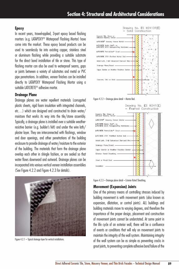
89Direct Adhered Ceramic Tile, Stone, Masonry Veneer, and Thin Brick Facades – Technical Design Manual
Section 4: Structural and Architectural Considerations
Figure 4.2.2 – Drainage plane detail – Mortar Bed.
Figure 4.2.3 – Drainage plane detail – Exterior Rated Sheathing.
Movement (Expansion) JointsOne of the primary means of controlling stresses induced by building movement is with movement joints (also known as expansion, dilatation, or control joints). ALL buildings and building materials move to varying degrees, and therefore the importance of the proper design, placement and construction of movement joints cannot be understated. At some point in the life cycle of an exterior wall, there will be a confluence of events or conditions that will rely on movement joints to maintain the integrity of the wall system. Maintaining integrity of the wall system can be as simple as preventing cracks in grout joints, to preventing complete adhesive bond failure of the
EpoxyIn recent years, trowel-applied, 3-part epoxy based flashing mortars (e.g. LATAPOXY® Waterproof Flashing Mortar) have come into the market. These epoxy based products can be used to seamlessly tie into existing copper, stainless steel or aluminum flashing while providing a suitable substrate for the direct bond installation of tile or stone. This type of flashing mortar can also be used to waterproof seams, gaps or joints between a variety of substrates and metal or PVC pipe penetrations. In addition, veneer finishes can be installed directly to LATAPOXY Waterproof Flashing Mortar using a suitable LATICRETE® adhesive mortar.
Drainage PlaneDrainage planes are water repellent materials (corrugated plastic sheets, rigid foam insulation with integrated channels, etc…) which are designed and constructed to drain water/moisture that works its way into the tile/stone assembly. Typically, a drainage plane is installed over a suitable weather-resistive barrier (e.g. builder’s felt) and under the wire lath/plaster layer. They are interconnected with flashings, window and door openings, and other penetrations of the building enclosure to provide drainage of water/moisture to the exterior of the building. The materials that form the drainage plane overlap each other in shingle fashion, or are sealed so that water flows downward and outward. Drainage planes can be incorporated into various vertical veneer installation assemblies (See Figure 4.2.2 and Figure 4.2.3 for details).
Figure 4.2.1 – Typical drainage layer for vertical installations.

90 Direct Adhered Ceramic Tile, Stone, Masonry Veneer, and Thin Brick Facades – Technical Design Manual
Section 4: Structural and Architectural Considerations
Figure 4.2.4 – Movement joints at corners.
Location – Dissimilar MaterialsDifferent materials have different rates and characteristics of thermal and moisture movement. Movement joints must be located wherever the cladding and underlying adhesive and leveling mortars meet a dissimilar material, such as metal window frames, penetrations, and any other type of exterior wall finish.
Location – Each Floor Level (Horizontal)Horizontal movement joints must be placed at each floor level (typically 10' –12' [3 – 3.7 m]) coinciding with the intersection of the top of the back-up wall and structural floor or spandrel beam above, or, at the lintel over the windows (see Section 3 – Architectural Details). This location not only isolates movement at each floor level, but also provides the architect the opportunity to incorporate movement joints into the design of the building façade in an aesthetically pleasing, rhythmic manner. Allowing for deflection movement between the spandrel beam or floor slab and the entire wall assembly is one consideration that often does not receive adequate attention.
Parapets, Freestanding/Projecting WallsCare should be taken to insure adequate movement joints at parapet or projecting wall locations. These areas of wall assemblies are typically exposed on both sides, resulting in greater movement stresses due to temperature extremes or wind.
The architect should take the opportunity and coordinate location of movement joints in these areas with architectural features, such as alignment with window frames, openings, columns, or other building features which accentuate a vertical or horizontal alignment.
cladding (which is the primary safety concern in direct adhered systems). Proper design and construction of movement joints requires consideration of the following criteria:
Criteria for Design of Movement Jointsn Locationn Frequencyn Size (width/depth ratio)n Type and detailing of sealant and accessory materials
Location of Movement JointsThe primary function of movement joints are to isolate the cladding from other fixed components of the building, and to subdivide the cladding assembly into smaller areas to compensate for the cumulative effects of building movement. While each building is unique, there are some universal rules for location of movement joints that apply to any direct adhered facade. For more information on the essentials for movement joints, please refer to the TCNA Handbook for Ceramic, Glass and Natural Stone Tile Installation, EJ-171.
Existing Structural Movement JointsMovement joints may already be incorporated in the underlying structure to accommodate thermal, seismic or wind loading. These joints must extend through to the surface of the cladding, and, of equal importance, the width of the underlying joint must be maintained through to the surface of the cladding.
Changes of PlaneMovement joints should be placed at all locations where there is a change of plane, such as outside or inside corners. It is very important to note that movement joints do not need to coincide at the exact intersection of corners. The general rule is that joints may be located within a maximum of 10' (3 m) from the inside or outside corner (Figure 4.2.4), or, the combined distance from joints on either side of the corner should not exceed the typical spacing of the joints.

91Direct Adhered Ceramic Tile, Stone, Masonry Veneer, and Thin Brick Facades – Technical Design Manual
Section 4: Structural and Architectural Considerations
Size of Movement Joints (Width/Depth Ratio)The proper width of a movement joint is based on several criteria. Regardless of the width as determined by mathematical calculations, the minimum functional width of a movement joint should be no less than 3/8" (10 mm); any joint narrower than this makes the proper placement of backer rods and sealant materials impractical, and does not provide adequate cover.
The width of a movement joint filled with sealant material must be 3 – 4 times wider than the anticipated movement in order to allow proper elongation and compression of the sealant. Similarly, the depth of the sealant material must not be greater than half the width for proper function (width/depth ratio). For example, if 1/4" (6 mm) of cumulative movement is anticipated between floor levels, the movement joint should be 1/2" – 3/4" (12 – 19 mm) wide and 1/4" – 3/8" (6 – 10 mm) deep (a rounded backup rod is inserted in the joint to control depth; see accessories below).
Type and Detailing of Sealant and Accessory MaterialsThe first and most often ignored step in the design of a movement joint is flashing or waterproofing the joint cavity. Sealant materials, no matter how well installed, are not 100% effective as a barrier against water penetration. There are several techniques used to provide a second barrier to water, depending on the depth of the joint cavity. The most common is the application of a thin, direct bond waterproofing membrane, which is applied at the leveling mortar surface, and looped down into the joint to provide for movement (Figure 4.2.6).
Figure 4.2.5 – Typical location of movement joints on a direct adhered facade.
Frequency (Spacing) of Movement JointsA conservative general rule for exterior facades is to locate movement joints at a frequency of no less than every 8' – 12' (2.4 – 3.7 m) in each direction (vertical and horizontal). With typical floor to floor heights less than 10' – 12' (3 – 3.7 m), a horizontal joint located at each floor level is usually sufficient to accommodate the vertical component of structural, thermal and moisture movement. Vertical joints to control the horizontal component of movement should be located every 8' – 12' (2.4 – 3.7 m) maximum, with more frequent spacing often dictated by architectural elements such as windows (Figure 4.2.5).
Exceptions to the general rules for design and construction of movement joints is when an engineer performs a mathematical calculation of movement, based on information pertinent to a particular project, which indicates either less or greater frequency, or, dimensions of the movement joints. An example would be greater frequency and/or width of movement joints required by a black ceramic tile in an extremely hot climate.
Example:
Determine the width of horizontal movement joints required at each floor level in a 10 story 120' (36.6 m) tall concrete frame building to control vertical movement only, with 12' (4 m) floor to floor heights. This calculation takes into account thermal, shrinkage, creep and elastic deformation together;
Anticipated temperature range is 150°F (66°C)
Thermal movement: 0.000006 x 40 m x 1000 mm x 66
= 15.8 mm
Shrinkage: 0.00035 x 40 m x 1000 mm
= 14 mm
Creep: 0.00065 x 40 m x 1000 mm = 26 mm
Elastic deformation: 0.00020 x 40m x 1000mm
= 8 mm
Total Anticipated Movement = 15.8 + 14 + 26 + 8
= 63.8 mm or 2.50"
Joint width aggregate: 3 x 63.8 (2.5") = 191.4 mm (7.5")
Total width of all joints: The 10 story building would have 11 horizontal joints, including the ground and roof levels: 191.4 mm/11 = 17.4 mm each joint (7.5"/11 = 0.68" each joint)

92 Direct Adhered Ceramic Tile, Stone, Masonry Veneer, and Thin Brick Facades – Technical Design Manual
Section 4: Structural and Architectural Considerations
an increase or decrease of 25% of the joint width), Use NT (non-traffic), Use M (bonds to mortar), Use I (submerged continuously), and Use G (glass).
Pre-fabricated movement joints, which typically consist of two L-shaped metal angles connected by a cured flexible material may not meet the above movement capability required for an exterior facade. Similarly, the selection of a non-corroding metal, such as stainless steel, is required to prevent corrosion by alkaline content of cement adhesives or galvanic reactions with other metals such as aluminum window frames. Consult with manufacturers of pre-fabricated movement joints to insure compliance with these criteria.
Pre-fabricated movement joints are commonly installed in advance of the cladding, so it is critical to prevent excessive mortar from protruding through the punched openings in the metal legs. The hardened mortar may subsequently prevent proper bedding of the cladding into the adhesive and lead to bond failure adjacent to the movement joint.
Figure 4.2.6 – Movement joint detail.
Rheological (Flow) PropertiesSealants must have sag-resistance equivalent to ASTM C920 “Standard Specification for Elastomeric Joint Sealants” Grade NS (non-sag for vertical joints).
Mechanical PropertiesSealants must have good elongation and compression, as well as tear resistance characteristics to respond to dynamic loads, thermal shock, and other rapid movement variations characteristic of an exterior facade.
After secondary flashing or waterproofing is complete, the movement joint must be fitted with a rounded backer rod, which is slightly larger in diameter than the joint width for a snug fit. The backer rod must be a closed cell polyethylene or similar material that will not allow the sealant to bond to it. The backer rod serves two important purposes:
1. Control of sealant depth for proper width/depth ratio.
2. To act as a bond-breaker with the sealant so that the sealant adheres only to the edges of the cladding. This allows the sealant material to elongate and compress freely, thereby preventing peeling stress at the tile edges (the primary cause of sealant joint maintenance problems and failure). If a joint does not have the depth to receive a backer rod, a polyethylene bond breaker tape can be used (commonly used for joints in thin-set floor applications).
The final step is selection and installation of the sealant joint material. There are many types of sealant products available on the market today, but only certain types are suitable for exterior facades and certain types of cladding materials. Sealants must meet the following basic functional criteria:
Criteria for Facade Movement Joint Sealantsn Dynamic performance – low modulus (flexible) with
extreme movement capabilityn Rheological properties – vertical sag resistancen Mechanical properties – resist tearing, elongation and
compression cyclesn Weatherability (ultraviolet resistance)n Chemical resistance – pollution and maintenance
chemicalsn Good adhesionn Compatibility with other materials (staining, corrosion)n Application method, safety/odor, life expectancy, cost
Dynamic PerformanceSealants for exterior facades must be high performance (also known as Class A or 25 rating), viscous liquid, neutral-cure type sealants capable of 25% movement over the life cycle. LATICRETE® Latasil™, a 100% silicone sealant, conforms to the following properties under ASTM C920 “Standard Specification for Elastomeric Joint Sealants”; Type S (single component), Grade NS (non-sag for vertical joints), Class 25 (withstands

93Direct Adhered Ceramic Tile, Stone, Masonry Veneer, and Thin Brick Facades – Technical Design Manual
Section 4: Structural and Architectural Considerations
Types of SealantsHigh performance sealants are synthetic, viscous liquid polymer compounds known as polymercaptans, polythioethers, polysulfides, polyurethanes, and silicones. Each type has advantages and disadvantages. As a general rule, polyurethane and silicone sealants are a good choice for ceramic tile, stone, masonry veneer, and thin brick facades.
Polyurethanes and silicones are available in one-component cartridges, sausages, or pails; some polyurethanes come in two-component bulk packages, which require mixing and loading into a sealant applicator gun. Both types of sealants are available in a wide range of colors.
Installation of sealants and accessories into movement joints requires skilled labor familiar with sealant industry practices. The installation must start with a dry, dust free surface/cladding edge. Some sealant products may require the use of a priming agent (e.g. LATICRETE Latasil 9118 Primer) as well. These primers are applied before the installation of the backer rod or bond breaker tape. Care must be taken to protect underlying flashing or waterproofing to avoid deterioration by primer solvents. Any excess mortar, spacers, or other restraining materials must be removed to preserve freedom of movement. The use of a backer rod or bond breaker tape is necessary to regulate the depth of sealant, and prevent three-sided adhesion. Once sealant has been applied, it is necessary to tool or press the sealant with special devices to insure contact with the tile edges; the backer rod aids this process by transmitting the tooling force to the tile edges. Tooling also gives the sealant a slightly concave surface profile consistent to the interior surface against the rounded backer rod. This allows even compression/elongation, and prevents visually significant bulge of the sealant under maximum compression.
Fire ResistanceOne of the inherent advantages of most direct adhered cladding systems are their natural fire resistant qualities. Some types of direct adhered systems, though, such as those employing silicone or epoxy adhesives, may be limited in their fire resistance by the loss of adhesive strength when exposed to high temperatures of a fire7.
Weather ResistanceSealant must be suitable for exposure to UV radiation (sun), moisture and temperature extremes; maintaining aesthetic appeal requires resistance to color fade, staining, and propensity for attracting contamination.
Chemical ResistanceSealant must withstand cleaning chemicals and atmospheric pollution.
CompatibilitySome sealants may stain porous stone or thin brick, or, curing by-products may be corrosive to concrete, stone, metals, or waterproofing membranes. There are dozens of types and formulations of sealant products, so it is important to verify compatibility. Compatibility varies by manufacturer’s formulations, and not by sealant or polymer type. For example, acetoxy silicones cure by releasing acetic acid and can be corrosive; neutral cure silicones do not exhibit this characteristic.
Fluid migration and the possible resultant staining is another compatibility issue to consider with sealants. There is no correlation with polymer type (i.e., silicone vs. polyurethane); fluid migration is dependent solely on a manufacturer’s formulation. Dirt pick-up is another common problem and is a function of type of exposure, surface hardness, type of and length of cure, and the formulation, but not the sealant polymer type. Fluid streaking though, depends on both formulation and sealant polymer type. There are several new generation silicones on the market, (such as LATICRETE Latasil) which have specifically addressed and overcome the above aesthetic problems associated with many sealants.
AdhesionSealants must have good tensile adhesion to non-porous or glazed surfaces of tile, ideally without special priming or surface preparation
Subjective CriteriaColor selection, ease of application, toxicity, odor, maintenance, life expectancy and cost are some of the additional subjective criteria that do not affect performance, but require consideration.

94 Direct Adhered Ceramic Tile, Stone, Masonry Veneer, and Thin Brick Facades – Technical Design Manual
Section 4: Structural and Architectural Considerations
pipes must be sealed with an intumescent sealant, which is a special material that is not only fireproof, but expands 5 – 10 times its original volume to displace consumed combustible material. This reaction protects against passage of fire and smoke from floor to floor.
Acoustical ControlSound transmission ratings of direct adhered wall assemblies are usually limited by the type and amount of fenestration (windows, doors, openings), with the fenestration being the weakest link in resisting airborne transmission of sound. Typically, windows with good air and water infiltration qualities will have good sound attenuation. Windows should be tested in accordance with ASTM E413 “Classification for Rating Sound Insulation” and/or ASTM E1332 “Standard Classification for Rating Outdoor-Indoor Sound Attenuation” to determine sound transmission class (STC) rating, which is a measure of airborne sound transmission.
In analyzing the sound attenuation of the wall construction, the transmission of sound is inversely proportional to the mass of the wall. So barrier type walls with lightweight back-up construction such as metal studs and cement backer board will not perform as well in resisting sound transmission as a cavity wall employing an inner and outer wall of masonry behind the direct adhered cladding material.
Figure 4.2.7 – Use of movement joints as an integral facade design element8.
Roofing and Parapet WallsOne of the most vulnerable parts of any exterior wall system is the interface between the roofing and the vertical parapet walls or roof fascia. Water often penetrates this critical intersection, so the design of direct adhered cladding must carefully consider detailing of waterproofing, flashing, and sealants in these areas to insure proper performance.
In many parts of the world, building codes regulate the required fire resistance and fire containment properties of exterior wall assemblies. Fire resistance of an exterior wall assembly primarily provides life safety for occupants by eliminating fuel for flame or smoke development, and remaining intact during exposure to heat. Fire containment differs from fire resistance in that containment is intended primarily for property protection by preventing the spread of fire within the building and to adjacent properties.
Fire resistance and containment requirements vary depending on the type of occupancy, size of the building, location to adjacent buildings, access for fire equipment, and the type of fire detection and suppression equipment available in the building, such as fire alarms and sprinkler systems. Because the ceramic tile, stone, masonry veneer, and thin brick materials used in direct adhered systems are thin, non-structural finishes and are inherently non-combustible, the underlying wall construction and detailing usually dictates overall fire resistance and containment performance. The fire resistance or containment properties of some types of direct adhered wall assemblies may be limited by the type of materials such as adhesives, or even by configuration alone.
Fire ContainmentCertain types of direct adhered wall assemblies are designed and installed in such a manner that no space exists between the wall and the floor. This type of configuration will not allow fire to pass through this space and spread to the next floor. However, some exterior wall designs contain a space between the floor and the wall, known as a “safe-off” space. Wide spaces (>1" [25 mm]) must be filled with a “fire stopping” material known as “safing” insulation, which is a type of mineral fiber mat that is friction fit in the void. Safing insulations are known to be ineffective in stopping passage of smoke under conditions of positive pressure, so they are typically combined with metal fire stopping plates.
Proprietary products of expanding (intumescent) foams or rigid metal plates of galvanized steel and fireproof material are also available for fire stopping large voids. Narrow spaces between exterior walls and floors may be fire stopped with fireproof sealants and putties, loose fibrous mineral fiber, or cement mortars and grouts. Any narrow openings penetrated by combustible materials, such as foam plastic insulation or

95Direct Adhered Ceramic Tile, Stone, Masonry Veneer, and Thin Brick Facades – Technical Design Manual
Section 4: Structural and Architectural Considerations
Parapet walls must be flashed or waterproofed beneath the top horizontal cladding surface (also known as the coping) in all types of wall construction to prevent water penetration through joints in the coping. Water entry at this point is the number one cause of water related problems in direct adhered cladding. Water which is trapped within the exterior wall is the primary cause of efflorescence, freeze-thaw deterioration, and strength reduction of cement adhesive mortars.
The direct adhered latex or portland cement latex membranes required for flashing or waterproofing of direct adhered barrier walls typically will not adhere to metal flashings. Latex membranes also are not compatible with many of the petroleum based built-up roofing materials, or the solvent based adhesives used for sealing/welding of seams in single-ply elastomeric (EPDM, PVC) sheet roof membranes. In order to assure a continuous watertight seal between latex membranes, it may be necessary to use urethane or silicone sealants to provide an adhesive seal between the membrane and dissimilar materials. However, an epoxy flashing material (e.g. LATAPOXY® Waterproof Flashing Mortar) may be considered to create a seamless flashing assembly when installed over a metal flashing and latex membrane while providing a suitable surface onto which tile, stone or other suitable cladding can be directly bonded.
Movement between the roof and parapet wall must also be analyzed, and allowances made in the flexibility of all connections. Parapet walls are the only part of the exterior wall assembly which is typically exposed to wind loading and wide temperature variations on both sides.

96 Direct Adhered Ceramic Tile, Stone, Masonry Veneer, and Thin Brick Facades – Technical Design Manual
Section 4: Structural and Architectural Considerations

97Direct Adhered Ceramic Tile, Stone, Masonry Veneer, and Thin Brick Facades – Technical Design Manual
Section 5: Substrates
97Direct Adhered Ceramic Tile, Stone, Masonry Veneer, and Thin Brick Facades – Technical Design Manual
Photo: Project-Umstead Hotel, Research Triangle Park, NC 2006, Architect: Three Architecture, Inc, Dallas, TX; Stone Contractor: David Allen Co., Raleigh, NC.Description: 20" x 30" (510 mm x 762 mm) limestone installed with LATAPOXY® 310 Stone Adhesive.

98 Direct Adhered Ceramic Tile, Stone, Masonry Veneer, and Thin Brick Facades – Technical Design Manual
Section 5: Substrates
5.1 CRITERIA FOR SELECTION OF SUBSTRATESIn Section 2, different types and configurations of direct adhered cladding systems were presented. In each type of wall, the cladding material was directly adhered to the outermost surface material of the back-up wall construction. In a composite adhesive system, this outermost surface is commonly referred to as the substrate. In addition to being the surface to which the cladding material is attached using adhesive, the substrate is also the (or part of the) principal load-bearing component of the exterior wall cladding assembly. Overlays of other materials over the primary substrate, such as waterproofing membranes, may also be considered a type of substrate. Overlays can provide more desirable characteristics of smoothness, hardness, or more durability such as resistance to water.
There are a wide variety of suitable substrates that can be used for direct adhered external cladding systems. These suitable substrates typically include concrete, concrete masonry units (CMU), brick, cement plaster, and cement backer board. The substrate selection process should start with a general evaluation of substrate properties and their fundamental compatibility with the external cladding system concepts.
The following criteria are considered important properties of a substrate for direct adhered external cladding:
DensityDensity of a material is defined as the weight per unit volume expressed in lbs/ft3 or grams/cm3. Many physical properties of a substrate depend to some degree on density. In general, as a materials’ density, strength and modulus of elasticity (stiffness) increase, the dimensional stability and porosity decreases.
PorosityGood adhesion does not necessarily require that a substrate be porous, as demonstrated by the adhesion of glass mosaics or use of metal substrates for external cladding. Nonetheless, porous substrates are generally easier to adhere to than non-porous substrates. When an adhesive can penetrate into the pores of a substrate and/or cladding material, the effective contact area is increased. This is an even more important concept for cementitious adhesive mortars commonly used in external cladding systems. The open pore structure not only
allows penetration of cement paste to increase contact area, but also allows crystal growth from cement hydration to occur within the substrate’s pores. This provides a mechanical locking effect as well as adhesive bond. Porosity also contributes to the removal of solvents or excess water and aids in strength development. However, high porosity may also cause excessive migration of hydration moisture from the adhesive interface, resulting in what is referred to as a “starved” adhesive layer.
Surface CharacteristicsThe ability of a substrate to be wetted by an adhesive is essential to good adhesion and important in determining compatibility between adhesives and substrates. This means that the substrate material must not only possess balanced porosity and surface texture, but also that the surface be free of any contamination such as dust or dirt that would prevent wetting and contact with an adhesive. The levelness tolerance and/or smoothness of a substrate surface (as well as the cladding surface) also play important roles in allowing proper contact and wetting by an adhesive.
Adhesive CompatibilityThe substrate material must be compatible not only with adhesive attachment, but also with the type of adhesive under consideration. This means that the substrate material must have good cohesive qualities to resist tensile and shear stress, and not have adverse reaction with the proposed adhesive. Similarly, the cladding material must also be compatible with adhesive attachment and type of adhesive (see Section 6). Some general considerations in determining compatibility with adhesives are as follows:
Asphaltic (petroleum based) Waterproofing Petroleum based products placed over the substrate surface are generally not compatible with tile or stone installation adhesives.
Steel and Other MetalsSteel or metal type of substrate usually requires an epoxy (e.g. LATAPOXY® 300 Adhesive), silicone or urethane adhesive due to the low porosity of steel/metal; portland cement or latex-portland cement adhesives do not develop adequate bond to metals without expensive preparation or special adhesive formulations.

99Direct Adhered Ceramic Tile, Stone, Masonry Veneer, and Thin Brick Facades – Technical Design Manual
Section 5: Substrates
Cementitious, Clay Masonry, and Mineral Based MaterialsThe wide variety of physical characteristics of this family of materials, especially the water absorption rate and texture of the surface, each requires adhesives with characteristics formulated for the material’s characteristics.
Dimensional Stability (Moisture Sensitivity)All materials have varying degrees of moisture sensitivity, and those materials with extreme sensitivity may result in excessive swelling, shrinkage, or deterioration, and are not suitable as substrates for direct adhered cladding. Some moisture exposure is inevitable, and will occur either through penetration of rain water, or from normal passage and condensation of water vapor through an exterior wall assembly. It is essential to evaluate compatibility and dimensional stability of the substrate for the application. While the substrate may have acceptable dimensional stability, evaluation of the differential movement between a substrate, the adhesive, and the cladding will assure minimal stress from restraint of dimensional changes.
Plywood and Other Wood Based Products – Wood or wood fiber based products generally have high water absorption rates, and undergo rates of volumetric swelling and subsequent shrinkage that make these materials unsuitable* as a substrate for direct adhered systems. The excessive differential movement between a wood substrate and the adhered cladding, and also between the wood and its supporting framework and fasteners can cause failure of the adhesive bond, the substrate material or the fasteners.
Gypsum Based Boards or Plasters – Gypsum based materials will typically deteriorate and lose the ability to support a direct adhered finish when exposed to moisture for prolonged periods.* Potential cohesive failure of a saturated gypsum substrate will subsequently result in failure of the direct adhered cladding.* Some proprietary wood fiber-cement and gypsum based products are fabricated with water resistant additives or surfaces; consult manufacturer for test data on moisture absorption, volume change, or deterioration and compatibility with direct adhered external cladding.
Clay (Brick) Masonry – Clay based materials undergo varying degrees of permanent volumetric expansion after prolonged exposure to moisture (see Section 6.5 – Thin Brick Masonry). This is an important consideration in a wet, humid environment, and necessitates the use of either waterproofing
membranes (especially with more porous stones), or a proper combination of flashings and sealants to prevent saturation of the underlying clay masonry substrate.
Clay brick masonry will permanently increase in volume as a result of the absorption of atmospheric moisture after removal from the kiln; this is an important design consideration. The total recommended design coefficient for moisture expansion as recommended by the Brick Institute of America is 3-4x 10⁻⁴/inch of length. Factors affecting moisture expansion are:
Time of Exposure – 40% of the total expansion will occur within the first three months after firing and 50% will occur within one year of firing.
Time of Installation – Moisture expansion will depend on the age of the brick and the remaining potential for expansion.
Temperature – The rate of expansion increases at higher temperature when moisture is present.
Humidity – The rate of expansion increases with the relative humidity. Brick exposed to a relative humidity (RH) of 70% will have moisture expansion rates two to four times as great as clay brick at 50% RH.
Dimensional Stability (Thermal Movement)Standard construction references contain information on the thermal coefficient of linear expansion for most common building materials (Fig 5.1.1). Data for proprietary products should be available from the manufacturer. This data will allow you to determine which substrate materials may have thermal movement properties which are significantly different than the adhered cladding material. Of somewhat less importance, is to analyze thermal movement compatibility with other components of the wall assembly. As an example, aluminum moves at almost three times the rate of limestone; that means for every 100' (30 m), the aluminum would expand approximately 1" (25 mm) more per 100°F (38°C) temperature change (which is not uncommon in a façade exposed to sun) than the limestone! The excessive build-up of stresses in the adhesive interface between these materials, even with a flexible adhesive, could result in failure.

100 Direct Adhered Ceramic Tile, Stone, Masonry Veneer, and Thin Brick Facades – Technical Design Manual
Section 5: Substrates
Stiffness (Modulus of Elasticity)Modulus of elasticity is the measure of the stiffness of a material. When substrates and cladding with different dimensional stability and stiffness are adhered, stress may develop from the restraint of dimensional change. The stress can manifest itself as shear stress in the adhesive layer, or in tensile or compressive force in the substrate. If these forces are balanced, the adhered wall assembly will remain stable. The optimum condition is to balance the stiffness of a substrate with the stiffness of the cladding to minimize restraining forces (by either the cladding or substrate) and thereby minimize shear, tensile, and compressive stresses.
Compliance with Building Codes and Industry StandardsBuilding or fire regulations may not allow certain materials to be considered as a substrate. As an example, cement backer board units (CBU) are a common substrate for direct adhered cladding. However, the CBU would typically be attached to a cold formed steel stud framework, either in a bearing, non-bearing, or curtain wall type of design (Section 2.2). A general rule of fire resistant construction is that while steel studs are incombustible, they quickly lose structural strength when exposed to high temperatures, and therefore, have a low fire rating unless protected by sprayed-on fireproofing or encapsulated with fire resistive construction. So a CBU substrate, while perfectly suitable in most other respects, may not meet fire or building code regulations due to the poor fire resistance of the support required to use that type of substrate product.
MATERIAL COEFFCIENT OF THERMAL EXPANSION (10-6 mm/
mm/C°)
Ceramic Tile 4 – 8
Granite 8 –10
Marble 4 –7
Brick 5 –8
Cement Mortar 10 –13
Concrete 10 –13
Lightweight Concrete 8 –12
Gypsum 18 –21
Concrete Block (CMU) 6 –12
Cellular Concrete Block 8 –12
Steel 10 –18
Aluminum 24
Copper 17
Polystyrene Plastic 15 –45
Glass 5 –8
Wood –Parallel Fiber 4 –6
Wood –Perpendicular Fiber 30 –70Figure 5.1.1 – Thermal coefficient of linear expansion for various materials Bold indicates typical exterior façade substrates.
Building codes also regulate, among other things, that a substrate meets the same minimum adhesion standards as the adhesive itself; in other words, the shear strength of a substrate material must meet minimum building code adhesive shear strength requirements for direct adhered cladding (50 psi [0.345 MPa]. It is anticipated that the 50 psi (0.345 MPa) will account for differential shear stress between the neveer and its backing in adhered veneer systems (ACI 530 6.3.2.4). For more information on building codes, please refer to Section 8.
Functional and Design CriteriaA substrate must meet project specific functional criteria (see Section 2.1). Functional criteria, though, are rarely satisfied by only the substrate, but more so by the substrate’s contribution to the performance of the entire wall assembly. For example, certain substrates may fail in controlling heat flow or sound, but the designer could re-configure the wall assembly to accommodate, for example, a wider cavity for additional sound and thermal insulation.

101Direct Adhered Ceramic Tile, Stone, Masonry Veneer, and Thin Brick Facades – Technical Design Manual
Section 5: Substrates
Cost, Availability, Site ConditionsRegional variations in cost, material and labor availability may make certain substrate materials more suitable than others. Limited construction equipment technology and experience with certain techniques and ancillary materials may also effect suitability of certain substrates. As an example, a very common substrate for a direct adhered external cladding is a cement/sand plaster applied over a relatively thin clay masonry back-up wall. This type of substrate is typically configured as a “barrier wall” (see Section 2.3), therefore, it relies heavily on the use of ancillary materials such as sealants, flashings, and waterproofing membranes to prevent water penetration and the issues of moisture expansion of the clay masonry, internal wall deterioration and efflorescence. Many of these ancillary materials are not readily available, and their proper detailing and use in direct adhered external cladding systems are not well understood. It is not only necessary for the designer to understand proper detailing and specification of these materials, but also for the builder to assure availability and proper knowledge of their use before any construction commences.
5.2 TYPES OF SUBSTRATESThe following is a list of many common substrates which are used in direct adhered external cladding systems. General information on common incompatible substrate materials, such as wood or gypsum, was covered in the preceding subsection on compatibility of adhesives and substrates. Detailed information on installation procedures for common substrates is beyond the scope of this manual. However, cement plasters/renders are often considered an integral component of the adhesive interface, so the materials and installation procedures for this common substrate are covered in detail at the end of sub-section 5.4 – Substrate Preparation.
Common Substrates for Direct Adhered External Cladding
n Concrete
– Cast-in-place concrete
– Pre-cast concrete panels
– Glass Fiber Reinforced Pre-Cast Concrete(GFRC) panelsn Concrete Masonry Units (CMU)
– Standard weight aggregate
– Lightweight aggregate
– Cellular concrete (aerated autoclaved concrete, gas beton, Ytong®)
n Clay masonry units
– Brick masonry
– Hollow clay masonryn Cement plasters/render (bonded or unbonded over metal
lath)
– Water/sand/cement/lime
– Latex/sand/cementn Cement Board Units (CBU)
– Cement board (e.g. PermaBase®, Util-A-Crete®, Durock®, etc…)
– Fiber cement underlayment (e.g. HardieBacker® Board)
– Calcium silicate boardn Corrugated sheet steeln Overlay materials
– Waterproofing membranes
– Skim/parge/bond coats
5.3 SUBSTRATE PREPARATION DESIGN AND CONSTRUCTION REQUIREMENTSThe cardinal rule for the installation of any material with an adhesive is; adhesion will only be as good as the materials and surfaces which are being adhered. The highest strength adhesives and most careful application to the best quality cladding will not overcome an improperly prepared substrate.
This section provides information on the identification of common substrate characteristics and defects, and the preventative and corrective actions necessary for proper surface preparation. Information on the evaluation and preparation of the cladding bonding surface is contained in Section 7.

102 Direct Adhered Ceramic Tile, Stone, Masonry Veneer, and Thin Brick Facades – Technical Design Manual
Section 5: Substrates
Structural requirements for substrates are contained in Section 4 under Live loads.
Sequence of Substrate Evaluation and Preparation
n Evaluation of type and surface condition of substraten Contamination removaln Final surface (residue) cleaning
Evaluation of Surface ConditionThe first step in substrate preparation is the evaluation of the type of substrate and its surface condition. This includes the levelness (plane or flatness deviation) and plumb (vertical deviation), identification of general defects, such as airborne contamination, as well as those defects specific to the substrate material or construction site location.
Plumb (Vertical) TolerancesIt is essential to evaluate the plumb (vertical) tolerances anticipated for a structure before making the decision to employ the direct adhered method for installation of ceramic tile, stone, masonry veneer, or thin brick cladding.Industry standards for concrete structures generally limit plumb tolerances to 1" (25 mm), but steel structures may have deviations up to 2" – 3" (50 – 75 mm). Certain types of exterior wall structures and types of wall configurations (see Section 2) can be designed to accommodate extreme plumb variations in the structural frame; others cannot. Correction of plumb deviations would include adjustment of the substrate’s underlying support or connections, or, to install a leveling mortar system. Exterior wall assemblies which are designed to run continuously in front of, and attach to, the structural frame rather than be supported or stacked on the structural frame, are eminently more adjustable to accommodate deviations from plumb.
Levelness TolerancesA flat, plane substrate is an important consideration for direct adhered facades using methods requiring full contact and coverage with adhesives. According to the Tile Council of North America TCA Handbook for Ceramic, Glass, and Stone Tile Installation “… when a cementitious bonding material will be used, including medium bed mortar: maximum allowable variation is 1/4" in 10' (6 mm in 3 m) from the required plane, with no more than 1/16" variation in 12" (1.5 mm in 300 mm) when measured from the high points in the surface.
For tiles with at least one edge15" (375 mm) in length, maximum allowable variation is 1/8" in 10' (3 mm in 3 m) from the required plane, with no more than 1/16" in 24" (1.5 mm in 600 mm) when measured from the high points in the surface. For modular substrate units (e.g. concrete masonry units) any adjacent edges must not exceed 1/32" (0.8 mm) difference in height. Should the architect require a more stringent finish tolerance, the subsurface specification must reflect that tolerance, or the tile specification must include a specific and separate requirement to bring the subsurface tolerance into compliance with the desired tolerance.” Greater deviations prevent the proper bedding of the cladding into the adhesive, which may result in numerous problems; the most serious being inadequate bond.
With regard to flatness of the finished veneer, the amount of substrate variation generally is reflected in the finished veneer installation. For any application requiring a flat surface, the installation should comply with the flatness requirements in ANSI A108.02: ‘no variations exceeding 1/4" in 10' (6 mm in 3 m) from the required plane. Conformance to this standard requires that the surface conform to the following: no variation greater than 1/4" in 10' (6 mm in 3 m), nor 1/16" in 12" (1.5 mm in 300 mm) from the required plane. For modular surfaces (e.g. cement backer units) adjacent edges cannot exceed 1/32" (0.8 mm) difference in height. In addition the effect from irregularities in the substrate increases as the veneer unit size increases. In these cases, a tighter subsurface tolerance may be required. The same levelness tolerances typically apply to the veneer. While most ceramic tiles suitable for exterior facades have very good calibration, the 1/8" (3 mm) tolerance corresponds to the acceptable deviation of thickness of most stones and bricks used for cladding. When choosing a cladding material, it is recommended to check the tolerances within the veneer unit to ensure that the proper preparation and installation/materials/methods are utilized.
If levelness tolerances are exceeded, then it is necessary to either implement remedial work such as re-construction, patching, grinding, or installation of a cement leveling mortar/render. If deviations are within acceptable industry tolerances, then it is acceptable to use an adhesive mortar within the adhesive manufacturer’s thickness limitations to level minor defects.

103Direct Adhered Ceramic Tile, Stone, Masonry Veneer, and Thin Brick Facades – Technical Design Manual
Section 5: Substrates
adhesives require a completely dry surface, which is typically achieved after waiting 2 – 3 days under ideal temperature and relative humidity (70°F [20°C] and 50% RH), with adequate protection from further contamination in the interim.* The soluble salts which can cause efflorescence, such as calcium chloride or sodium chloride, can act as accelerants when contacted by wet cement based adhesives or leveling mortars/renders.
Salt ContaminationSoluble salts such as calcium chloride or sodium chloride, can inhibit initial bonding or cause bond failure of cement based adhesives or leveling mortars/renders. There are several mechanisms that can cause these problems. Soluble salts, whether present from airborne material, or other sources of contamination, can act as accelerants when contacted by wet cement based adhesives or leveling mortars/renders. This may result in reduced bond strength, depending on the degree of contamination. Similarly, salt contamination of a substrate may allow efflorescence to develop at the substrate interface, possibly resulting in delamination from the expansive force caused by the growth of salts crystals (see Section 9 – Efflorescence). There are chemical tests and test equipment that are available to determine the presence of salts (see Section 9 – Salt Contamination Testing).
Moisture Content (Dampness) of SubstratesCertain materials used in direct adhered wall assemblies are moisture sensitive. For example, the strength of cementitious adhesives can be reduced from constant exposure to wet or damp substrates. Some materials, such as waterproofing membranes, may not cure properly or delaminate from a continually damp or wet substrate. A damp substrate may also contribute to the formation of efflorescence (see Section 9 – Efflorescence). This is of particular concern not only due to prolonged periods of rain exposure during construction, but also in areas of a facade which may be exposed to rising dampness at ground level, and in areas where leaks from poor design or construction cause continual dampness in the substrate.
There are several methods that can be used to determine acceptable moisture content and relative humidity of substrates prior to application of moisture sensitive coatings (see Section 9 – Testing.) The percentage of moisture content is not a meaningful test method for cementitious materials. The measurement of relative humidity in the concrete when tested per ASTM F2170 “Standard Test Method for
Direct adhered facades employing “spot” bonding using epoxy adhesive mortars (e.g. LATAPOXY® 310 Stone Adhesive or LATAPOXY 310 Rapid Stone Adhesive) can tolerate greater deviations from a flat plane; maximum deviation is a function of the recommended thickness and working properties such as sag resistance, as well as cost of the specific adhesive.
Climatic and Site ConditionsThe following surface defects apply to all substrates, although the degree of preparation to correct these conditions will vary with surface textures and other physical properties of different materials.
Airborne ContaminationWall substrate surfaces to receive direct adhered cladding will always be exposed to varying degrees of airborne contaminants, especially normal construction site dust and debris. Similarly, building sites located near the sea, deserts, or industrial areas may be subject to airborne salt, sand, or acidic rain/pollution contamination, especially if there is a significant lapse of time between the completion of the substrate work and adhesion of the cladding or leveling mortar/render. Dust films may inhibit adhesive bond, salt deposits may cause a film of efflorescence*, and wind-blown sand may prevent initial grab of adhesive mortars by producing a “ball bearing” type effect during spreading, which makes application difficult. As a result, the minimum required preparation for substrates is washing with high pressure water (or standard pressure water with agitation if high pressure water is not available) to eliminate the bond breaking effect and other problems that could result from surface contamination. In some cases, airborne contamination is constant, requiring frequent washing just prior to installation of cement leveling plaster/renders or adhesive mortars.
Washing a surface in preparation for application of adhesives is mandatory, the only variable is the moisture content and required drying time of the substrate prior to application of the adhesive. Moisture content and drying time is dependent on the type of adhesive being used (see Section 7). With most adhesives or cement leveling mortars/renders, such as cement latex mortars or moisture insensitive epoxy adhesives, the substrate can be damp (also known as saturated surface dry condition or SSD), but not dripping wet; a surface film of water can inhibit grab and bond of even water insensitive cement and epoxy based adhesives. Silicone or urethane

104 Direct Adhered Ceramic Tile, Stone, Masonry Veneer, and Thin Brick Facades – Technical Design Manual
Section 5: Substrates
LaitanceThis is the term for a surface defect in concrete where a thin layer of weakened portland cement fines have migrated to the surface with excess “bleed” water or air from unconsolidated air pockets. This condition is especially prevalent in vertically formed concrete, where excess water migrates by gravity, aided by the vibration of concrete and pressure of the concrete to the surface of the wall form. The excess water then gets trapped by the forms. Once the excess water evaporates, it leaves behind a thin layer of what appears to be a hard concrete surface, but in reality is weakened due to the high water to cement ratio at the surface. Laitance has a very low tensile strength, and therefore, the adhesion of ceramic tile, stone, masonry veneer, thin brick or cement leveling mortar/render will be limited by the low strength of the laitance. There are proprietary fabric products available for lining concrete forms that drain excess water and optimize the water/cement ratio near the surface of the concrete. These products virtually eliminate laitance and “bug holes” (caused by air pockets) and all the extra preparation necessary to remove or repair these defects prior to direct adhesion to concrete.
Carbonation (Cold Climates)Carbonation of a concrete or cement based surface occurs when atmospheric carbon dioxide reacts with wet concrete or cement based material. Carbonation stops the chemical hydration process of cement and ends strength gain in cement based materials. This results in low compressive and tensile strength of the surface, possibly progressive to internal zones, depending on the length of exposure and the degree of carbon dioxide concentration in the atmosphere.
This condition typically occurs when ambient temperatures during placement and finishing are around 40°F (5°C). It only affects exposed surfaces, so cement plaster/render substrates (see Section 5.4 – Cement Plaster/Render) are more at risk than vertical concrete protected by form work. The length of exposure is a function of temperature. Cement hydration stops at a surface temperature of 32°F (0°C) when water necessary for hydration freezes, and, hydration is retarded starting at 40°F (5°C). Concentration of carbon dioxide can be elevated when temporary heating units are not properly vented outside of any protective enclosure during
Determining Relative Humidity in Concrete Floor Slabs Using in-situ Probes” is the most appropriate method. For horizontal, indoor installations the use of testing in compliance with ASTM F2170 along with testing as per ASTM F1869 “Standard Test Method for Measuring Moisture Vapor Emission Rate of Concrete Subfloor Using Anhydrous Calcium Chloride” provides an even greater view into what is happening with the moisture state of concrete. For tile or stone installations using LATICRETE® materials, the moisture content of cementitious substrates is typically only an issue when a membrane (e.g. LATICRETE Hydro Ban®) will be implemented.
Surface and Ambient TemperatureDuring the placement of concrete and installation of other types of substrates, extreme cold or hot temperatures may cause numerous surface or internal defects, including shrinkage cracking, a weak surface layer of hardened concrete caused by premature evaporation, or frost damage. Once the adhesive is cured, extreme temperatures of both the ambient air and surface of the substrate may also affect the normal properties of adhesive.
Elevated ambient air (80 – 100°F [27 – 38°C]) and surface (≥95°F [35°C]) temperatures will accelerate setting of cement, latex cement, and epoxy adhesives. Washing and dampening walls as described above will not only remove contaminants, but also serve to lower surface temperatures for cement latex mortars and moisture insensitive epoxy adhesives. Shading surfaces is also effective in lowering surface temperature, but if ambient temperatures exceed 100°F (38°C), it is advisable to defer work with adhesives to another time. A standard rule of thumb is: For every 18°F (10°C) above 70°F (21°C) cementitious and epoxy materials cure twice as fast. For every 18°F (10°C) below 70°F (21°C) cementitious and epoxy materials take twice as long to cure.
Material Specific Substrate Preparation – Cast-in-Place ConcreteThe condition of vertically formed concrete is extremely variable, due to the numerous potential defects that can occur with mix design additives, forming, placement and curing. The following is detailed information on the identification and causes of common external surface defects in vertically cast-in-place concrete.

105Direct Adhered Ceramic Tile, Stone, Masonry Veneer, and Thin Brick Facades – Technical Design Manual
Section 5: Substrates
oily or other potential bond-breaking contaminant must be removed prior to direct adhesion to concrete. However, many of the proprietary products available are either chemically reactive with minerals in the concrete, or are self-dissipating through oxidation when exposed to adequate sunlight. As a result, these types of form release materials may not require removal prior to direct adhesion to the concrete. It is advisable to consult manufacturers’ test data and/or conduct sample tests to substantiate performance claims. It should be noted that self-dissipating curing agents require interaction with certain environmental conditions (e.g. direct sunlight). To ensure that these potential bond inhibiting materials (even self-dissipating materials) are completely removed, they must be physically removed by mechanical methods. Check with the manufacturer of the tile/stone adhesive for substrate preparation requirements and applicability of any warranties to improperly prepared substrates.
Curing CompoundsThe variety of materials and the unique characteristics of proprietary formulations require that you follow the same recommendations as above for form release agents. For more information, please refer to LATICRETE TDS 154 “Concrete Curing Compounds and Surface Hardeners” available at www.laticrete.com.
Concrete AdditivesSimilar to release and curing agents, there are numerous concrete additives, which, depending on the properties they impart to the concrete, could be detrimental to direct adhesion. For example, super-plasticizers are a type of additive that may allow for extremely low water to cement ratios and resultant high strength, without sacrificing workability of the concrete. This type of additive can induce bleed water, and facilitate the formation of laitance. Similarly, additives that react with free minerals in the concrete to produce an extremely dense and water resistant pore structure may be detrimental to good adhesive bond.
Concrete Curing – Age of ConcreteThe age of a concrete substrate just prior to direct adhesion of cladding or a cement leveling plaster/render is important. As concrete cures and loses moisture, it shrinks. A common misconception is that concrete completes shrinkage in 28
cold temperatures. Temperatures should be maintained above 50°F (10°C) during placement, initial removal of forms, and installation of cement based products.
HoneycombingThis is a condition where concrete is not properly consolidated by vibration, where reinforcement is located too close to the forms, where there is internal interference with the flow of concrete during the consolidation procedure, or where there is poor mix design. These conditions result in voids in the surface of the concrete. These voids must be properly prepared and patched using a bonding agent to insure proper adhesion to the concrete prior to adhesion of any cladding material or cement leveling plaster/render.
Unintended Cold (Construction) JointsIn vertical walls, cold joints are usually unintended, and can result in a weakened plane subject to random shrinkage cracking which could transfer to the external cladding surface. Cold joints are caused by rapid drying at the top surface of a concrete lift (typically from hot, dry wind), or from poor consolidation (failure to break up the initial set of the top surface). These conditions usually result from delays or equipment breakdowns. They can be prevented by coordination of concrete delivery and proper maintenance and use of vibration equipment.
Steel and Plastic Concrete FormsSteel or other types of smooth formwork can result in an extremely smooth and dense surface, which is typically not desirable for direct adhesion of a cladding, because this type of surface provides no mechanical key for the initial grab required when applying wet cement based adhesive mortars. Smooth and dense surfaces do not facilitate absorption of cement paste and the subsequent mechanical locking effect provided by the growth of cement crystals into the pores of the surface. Epoxy and silicone adhesives are less affected, as they do not rely on an open pore structure to achieve suitable adhesion.
Form Release AgentsThere are a wide variety of form release materials and products in use today, ranging from simple used motor oil to more sophisticated water based proprietary products. Any type of

106 Direct Adhered Ceramic Tile, Stone, Masonry Veneer, and Thin Brick Facades – Technical Design Manual
Section 5: Substrates
Structural CrackingCracks that are approximately 1/8" (3 mm) in width or greater, and occur throughout the cross section of a concrete wall or structural member, are an indication of a structural defect and must be corrected prior to direct adhesion of any materials. Structural cracking of vertical concrete can only be repaired using low-viscosity epoxy or methacrylate pressure injection methods. Cracks that are less than 1/8" (3 mm) are typically non-structural shrinkage cracks. While these types of cracks do not require structural correction, they either require isolation by means of a flexible crack suppression membrane, or repair with an epoxy or methacrylate injection to prevent further movement and transfer of stress to the adhesive interface or cladding surface.
Special Concrete Preparation MethodsIn Japan, a simple technique was developed to minimize surface preparation of vertically formed concrete before installation either of cement leveling plaster/renders or direct application of cladding. The method, known as the Mortar-Concrete Rivet-back System (MCR), employs polyethylene bubble sheet plastic form liners, which when removed, result in an imprinted concrete surface which provides a mechanical locking effect and increases the safety factor for adhesion of leveling plasters/renders or adhesive mortars.
The plastic is stapled to forms with stainless steel staples and the concrete is placed. After initial curing, the forms are removed, leaving the plastic in place. The plastic is then stripped in a separate procedure prior to installation of leveling or adhesive mortars in order to protect the surface from site contamination and aid in curing of the concrete in the initial 28 days of strength gain. The plastic liners also eliminate the use of form release agents and contribute to easy cleaning and longevity of forms. This method requires a minimum of 30 – 45 days prior to application of plaster/render or direct application of cladding in order to allow the initial period of high drying shrinkage to occur.
Concrete Masonry Units (CMU)Concrete masonry units (CMU) are very suitable as a substrate for external cladding. When standard aggregate and density CMU is built to plumb and levelness tolerances from the exterior rather than from the interior of the wall, no further preparation, except final water cleaning, is typically necessary.
days; this is not true. Thick sections of concrete may take over 2 years to reach the point of ultimate shrinkage. 28 days is the period of time it takes for concrete to reach its full design strength. At that point, concrete should reach maximum tensile strength, and can better resist the effects of shrinkage and stress concentration. Depending on the humidity and exposure to moisture in the first 28 days, there may be very little shrinkage that occurs within that period. So while more flexible adhesives, like latex cement adhesive mortars or silicone adhesives, can accommodate the shrinkage movement and stress that may occur in concrete less than 28 days old, it is recommended to wait a minimum of 30 – 45 days to reduce the probability of concentrated stress on the adhesive interface. Building regulations may require longer waiting periods of up to 6 months. After this period, resistance to concentrated stress is provided by the tensile strength gain of the concrete, and its ability to shrink as a composite assembly. The effect of remaining shrinkage is significantly reduced by its distribution over time and accommodated by the use of low modulus or flexible adhesives.
Plastic and Drying Shrinkage CrackingFreshly placed concrete undergoes a temperature rise from the heat generated by cement hydration, resulting in an increase in volume. As the concrete cools to the surrounding temperature, it contracts and is susceptible to what is termed “plastic shrinkage” cracking due to the low tensile strength within the first several hours or days. Plastic shrinkage can be controlled by reduction of aggregate temperature, cement content, size of pours/members, deferring concreting to cooler temperatures, damp curing, and the type or early removal of forms.
Concrete also undergoes shrinkage as it dries out, and can crack from build-up of tensile stress. Rapid evaporation of moisture results in shrinkage at an early stage where the concrete does not have adequate tensile strength to resist even contraction. Concrete is most susceptible to drying shrinkage cracking within the first 28 days of placement during which it develops adequate tensile strength to resist a more evenly distributed and less rapid rate of shrinkage. It is for this reason that it is recommended to wait 30 – 45 days before application of cement plaster/render coats or direct application of adhesive mortars.

107Direct Adhered Ceramic Tile, Stone, Masonry Veneer, and Thin Brick Facades – Technical Design Manual
Section 5: Substrates
typical cladding materials to cause concern about differential movement. The porous structure of this material also requires careful consideration to compensate for the loss of hydration moisture from cement based adhesives.
Cellular CMU may not be suitable as a primary substrate for direct adhered cladding without special preparation or the use of flexible (low modulus) adhesives. The recommended preparation would require a cement plaster/render a minimum of 1" (25 mm) nominal thickness applied over galvanized steel lath or mesh anchored to the cellular block with special plastic anchors. In some cases, the direct application of a low modulus latex cement mortar may distribute shear stress effectively over a large enough area. However, full scale mock-up testing is recommended to verify suitability and acceptability for direct adhesion.
Clay (Brick) Masonry UnitsClay brick masonry units used in backup infill wall construction will permanently increase in volume as a result of absorption of atmospheric moisture after removal from the kiln after firing, this is an important design consideration in preparation of this substrate material. In order to prevent problems with differential movement, it is recommended that the design coefficient of moisture expansion should not exceed 3-4x10⁻⁴" of length as recommended by the Brick Institute of America (BIA). Factors affecting substrate preparation and subsequent installation of cladding are:
Time of Exposure – 40% of the total expansion will occur within three months of firing and 50% will occur within one year of firing.
Time of Installation – moisture expansion will depend on the age of the clay masonry and the remaining potential for expansion. If possible, use clay masonry which has had as much time to acclimate to moisture as possible.
Temperature – the rate of expansion increases at higher temperatures when moisture is present.
Humidity – the rate of expansion increases with the relative humidity. Brick exposed to a relative humidity of 70% will have moisture expansion rates two to four times as great as exposure to 40–50% relative humidity.
A primary concern in preparation of this substrate, when used as an infill back-up wall between a concrete structure, is the risk of shrinkage. The amount of shrinkage is dependent on the lapse of time from manufacture, as well as the degree of drying (humidity levels or rain exposure during storage and handling). Shrinkage stress may accumulate as the CMU dries after installation, and may be released at the connection between the concrete and the CMU (typically the weak link). Therefore, it is recommended to follow guidelines for proper reinforcement and shrinkage control anchorage to the concrete structure (see Section 3 – Architectural Details). It is also recommended to consider using a crack suppression membrane to bridge the surface of this intersection and dissipate the shrinkage stress as added protection from future shrinkage. These techniques, together with the use of flexible adhesives and flexible additives to cement plasters/renders, will eliminate the need for placing movement joints at all these locations to prevent shrinkage cracks or stress on the cladding adhesive interface.
Standard Aggregate and Lightweight Aggregate Concrete Masonry Units (CMU) present several other material specific concerns. CMU is typically fairly porous, and care (or corrective action) must be taken to prevent possible loss of moisture required for proper hydration of latex cement adhesive mortars. In some cases where test panels may indicate poor adhesion at the CMU/adhesive interface, it is recommended to skim coat the CMU (1/8" [3 mm] maximum thickness) with a latex cement mortar to seal the rough surface texture of the CMU. With the proper latex additive, the thin skim coat will harden quickly without risk of moisture loss. Another concern is that the cohesion or tensile strength of the CMU material may be less than the tensile bond strength of the adhesives; this is more of a concern with lightweight aggregate or cellular CMU.
Aerated Autoclaved Concrete (AAC), Cellular or Gas Beton CMU, which are manufactured with gases to entrain air and reduce weight and density, typically do not have good tensile and shear strength (<7 kg/cm2). Due to the low shear strength of these materials, slight shrinkage of conventional cement mortars may tear the surface of the blocks and result in delamination. Similarly, the low density (40–50 lbs/ft3 [500–600 kg/m3]) of these materials results in a coefficient of thermal expansion which is significantly different from
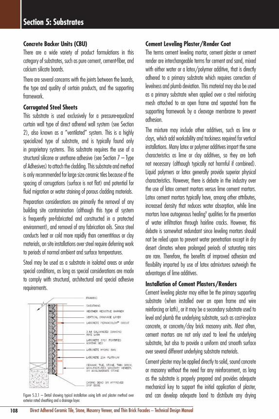
108 Direct Adhered Ceramic Tile, Stone, Masonry Veneer, and Thin Brick Facades – Technical Design Manual
Section 5: Substrates
Cement Leveling Plaster/Render CoatThe terms cement leveling mortar, cement plaster or cement render are interchangeable terms for cement and sand, mixed with either water or a latex/polymer additive, that is directly adhered to a primary substrate which requires correction of levelness and plumb deviation. This material may also be used as a primary substrate when applied over a steel reinforcing mesh attached to an open frame and separated from the supporting framework by a cleavage membrane to prevent adhesion.
The mixture may include other additives, such as lime or clays, which add workability and tackiness required for vertical installations. Many latex or polymer additives impart the same characteristics as lime or clay additives, so they are both not necessary (although typically not harmful if combined). Liquid polymers or latex generally provide superior physical characteristics. However, there is debate in the industry over the use of latex cement mortars versus lime cement mortars. Latex cement mortars typically have, among other attributes, increased density that reduces water absorption, while lime mortars have autogenous healing9 qualities for the prevention of water infiltration through hairline cracks. However, this debate is somewhat redundant since leveling mortars should not be relied upon to prevent water penetration except in dry desert climates where prolonged periods of saturating rains are rare. Therefore, the benefits of improved adhesion and flexibility imparted by use of latex admixtures outweigh the advantages of lime additives.
Installation of Cement Plasters/RendersCement leveling plaster may either be the primary supporting substrate (when installed over an open frame and wire reinforcing or lath), or it may be a secondary substrate used to level and plumb the underlying substrate, such as cast-in-place concrete, or concrete/clay brick masonry units. Most often, cement mortars are not only used to level the underlying substrate, but also to provide a uniform and smooth surface over several different underlying substrate materials.
Cement plaster may be applied directly to solid, sound concrete or masonry without the need for any reinforcement, as long as the substrate is properly prepared and provides adequate mechanical key to support the initial application of plaster, and can develop adequate bond to distribute any drying
Concrete Backer Units (CBU)There are a wide variety of product formulations in this category of substrates, such as pure cement, cement-fiber, and calcium silicate boards.
There are several concerns with the joints between the boards, the type and quality of certain products, and the supporting framework.
Corrugated Steel SheetsThis substrate is used exclusively for a pressure-equalized curtain wall type of direct adhered wall system (see Section 2), also known as a “ventilated” system. This is a highly specialized type of substrate, and is typically found only in proprietary systems. This substrate requires the use of a structural silicone or urethane adhesive (see Section 7 – Type of Adhesives) to attach the cladding. This substrate and method is only recommended for large size ceramic tiles because of the spacing of corrugations (surface is not flat) and potential for fluid migration or water staining of porous cladding materials.
Preparation considerations are primarily the removal of any building site contamination (although this type of system is frequently pre-fabricated and constructed in a protected environment), and removal of any fabrication oils. Since steel conducts heat or cold more rapidly than cementitious or clay materials, on site installations over steel require deferring work to periods of normal ambient and surface temperatures.
Steel may be used as a substrate in isolated areas or under special conditions, as long as special considerations are made to comply with structural, architectural and special adhesive requirements.
Figure 5.3.1 – Detail showing typical installation using lath and plaster method over exterior rated sheathing and a drainage layer.

109Direct Adhered Ceramic Tile, Stone, Masonry Veneer, and Thin Brick Facades – Technical Design Manual
Section 5: Substrates
A plaster/render coat is typically 1" (25 mm) nominal thickness, applied in separate 1/2" (12 mm) applications or “lifts,” with the first coat known as the scratch coat and the second as the brown coat. The second lift should be applied as soon as the first or scratch coat is rigid, usually the next day. The short delay promotes intimate contact between coats and promotes curing of the scratch coat. Thinner coatings are acceptable as long as provision has been made to compensate for the risk of premature moisture evaporation common in thinner sections of cement materials. Thicker applications risk excessive shrinkage due to the gradation of aggregates in some mixes. There is also a risk of slumping/delamination from the substrate caused by weight of the material exceeding the wet adhesive strength to the substrate, or cohesive strength of the cement plaster/render.
When used as a leveling coat over other substrates, cement plasters may be either directly adhered to, or, isolated from the substrate with reinforcing mesh and a cleavage membrane as described above.
It is always recommended that a direct adhered plaster/render coat incorporate latex/polymer admixture into the mix to act as a bonding agent, as well as to improve the physical properties. At a minimum, it is recommended to employ a bonding coat (e.g. LATICRETE® 254 Platinum scratch coat) between the interface of a traditional sand/cement/lime mixture or proprietary thick bed mortar mix (e.g. LATICRETE 3701 Fortified Mortar Bed), and the underlying substrate. Bond coats, also known as “spritz,” “spatter dash,” or “dash” coats, can also be used effectively to insure good mechanical bonding. These mixtures are prepared using sand and cement, gauged with either water or latex additive, and cast or dabbed onto the substrate with a bristle brush, or even pumped and sprayed with mechanical equipment. Left to dry, the rough texture of these types of bond coats provides support and mechanical key for the initial application of cement plaster.
shrinkage stress without cracking. The use of latex additives and bonding agents enhance bond and establish some ability to accommodate differential movement caused by minor shrinkage (see preceding paragraph on additives). Metal reinforcement or wire lath should be used whenever cement plaster is applied over the following substrates or under the following conditions:
n Open frame construction (wood or metal studs)n Sheathed frame construction that does not provide
adequate mechanical key or bond for direct adhesionn Solid substrates (concrete, masonry) which are not suitable
for direct bondn Design conditions that require maximum isolation from
underlying movement (seismic zones)
ASTM C1063 “Standard Specification for Installation of Lathing and Furring to Receive Interior and Exterior Portland Cement-Based Plaster” provides guidelines for cement plaster reinforcement.
Whenever plaster is applied to metal reinforcement which is supported by a solid substrate, a cleavage membrane should be used to prevent partial bond of the plaster to the substrate, which can cause cracking. Metal reinforcement should be discontinuous across movement joints in the cement plaster/render. Metal reinforcement is available in several different forms:
Types of Metal Reinforcement for Cement Plaster/Render
n Expanded diamond metal lathn Woven wire fabricn Welded wire fabric
Expanded diamond mesh should be fabricated from galvanized steel, and weigh a minimum of 3.4 lbs/yd2 (1.9 kg/m2). Metal lath for exterior use should comply with ASTM C847 “Standard Specification for Metal Lath”.
Woven wire fabric should be fabricated from galvanized steel, and be configured with 1-1/2" (38 mm) or 1" (25 mm) hexagonal openings and weaved together in a particular configuration.
Welded wire fabric is a grid of cold-drawn, 16 gauge galvanized steel formed in squares or rectangles with openings not greater than 2" x 2" (50 x 50 mm) and welded at their intersections.

110 Direct Adhered Ceramic Tile, Stone, Masonry Veneer, and Thin Brick Facades – Technical Design Manual
Section 5: Substrates
Figure 5.3.3a and 5.3.3b – Proper protection of an exterior façade tile or stone installation during winter months in cold climate.
One of the most often asked question regarding exterior facade installations is how long to wait after the finish of the cement leveling plaster/render before installing the cladding material. The cladding should not proceed before the shrinkage of the render coat/ plaster is complete. The thicker the render coat is applied, the greater the chance of shrinkage. A cement plaster/render will undergo about 95% ultimate shrinkage in the first 7–14 days, so it is recommended to begin installation of cladding after waiting a minimum of 21 days from completion of the plaster/ render, or longer if there is a prolonged period of rain which may delay shrinkage. Latex or polymer modified cement plasters typically have higher density and lower water/cement ratios, therefore, they do not shrink as much as conventional cement mortars. If the cement plaster/render is mixed with latex, and if the cladding is installed with a latex or polymer fortified adhesive mortar, the reduced shrinkage and increased flexibility may allow installation of cladding within the 7–14 day period. However, both the manufacturer of the products and local building codes must be consulted.
Upon completion of the leveling coat (preferably after the 21 day waiting period), it is recommended to conduct appropriate inspection and testing to determine the quality of adhesion and any other defects before proceeding with the installation of cladding (See Section 9 – Acoustic Tap, Tensile Pull, Ultrasonic Testing).
Figure 5.3.2 – Sprayer/Pumper for cementitious plasters/renders. Example shown: ChemGrout CG-575 Series Thick Mix Sprayer/Pump – Trailer Mounted Max. output 2 – 8 GPM; max pressure 261 psi (18 bars). Material and job versatile. Mixes and pumps or sprays thick to thin materials including repair mortars, gel mortars, grouts, plasters, stucco, EIFS, fireproofing, cement/sand, cement/fly ash, flowable and non-flowable grouts, Bentonite waterproofing grouts.
There are additional important installation techniques to consider. Similar to mechanical application of bond coats for cement leveling mortars, the scratch and brown (float) coats of mortar may also be spray applied using mechanical pumps and compressed air (See Figure 5.3.2)10 and finished manually. If latex additives are employed, consult with both the equipment and additive manufacturer to determine if special types or dilution of additives/plasticizing agents or pump aids are required to prevent gumming and blockage of the spray equipment.
The proper manual procedure for installing the plaster/render coat is to apply by pressing the trowel with the mortar against the wall, and not by throwing it onto the wall. The mortar should be worked into the surface with a wood or plastic trowel to avoid blisters on the surface, taking care to observe thickness limitations. Make multiple applications to achieve the desired thickness, and then proceed with standard plaster /render techniques to screed and finish the mortar. Do not over trowel the surface; this is a “brown” or rough surface intended to receive an adhesive coating.
In extremely hot weather, follow guidelines for cooling wall surfaces with the final water wash preparation just prior to application of the plaster/render. Latex additives and damp curing are also highly recommended in hot weather to prevent premature evaporation of hydration moisture. It is also recommended to defer work if ambient surface temperatures exceed 95°F (35°C). In cold weather, the cure of the mortar will be retarded and there is a risk of damage if the temperature falls below 32°F (0°C); protection with tenting and longer cure times beyond the 14 day waiting period may be necessary before proceeding with installation of cladding.

111Direct Adhered Ceramic Tile, Stone, Masonry Veneer, and Thin Brick Facades – Technical Design Manual
Section 5: Substrates
Mechanical Chipping, Scarifying and GrindingFor preparation of walls, this method is recommended only when substrate defects and/or contamination exist in isolated areas and require bulk surface removal greater than 1/4" (6 mm) in depth. Chipping with a pneumatic square tip chisel or grinding with an angle grinder is a common technique.
Shot-BlastingThis is a term for a surface preparation method which uses proprietary equipment to bombard the surface of concrete with pressurized steel pellets. The pellets, of varying diameters, are circulated in a closed, self-contained chamber which also removes the residue in one step. This is the preferred method of substrate preparation when removal of a thin layer of concrete surface is required, especially removal of surface films or existing painted concrete. However, only hand held equipment is currently available for vertical concrete, so preparing large areas with this method is inefficient.
Sand-Blasting/Grit-BlastingThe coatings industry now employs a new generation of cleaner, safer, and less intrusive grit-blasting which employs water soluble low-silica grit materials (sodium bicarbonate). Sand-blasting is acceptable if other safer and less intrusive methods of bulk removal are not available.
Water BlastingHigh pressure water blasting using pressures over 3,000–10,000 psi (21–69 MPa) will remove the surface layer of concrete and expose aggregate to provide a clean, rough surface. Thorough rinsing of the surface with water after water blasting is necessary to remove any weakened cement paste (laitance) residue. Water blasting is only recommended on concrete because the high pressure will damage surfaces of thin, less dense materials such as cement boards or brick masonry.
Chemical Cleaning (Salt Removal)Proprietary chemical cleaners are available to remove soluble salts from a substrate surface prior to adhesion of cladding or cement plasters/renders.11 These chemicals can be used with any type of preparation method that incorporates water, from hand washing to water blasting. Salt contamination can contribute to adhesion failure (See Section 9.4).
Assuming there are no problems, the surface of the plaster/render should receive a final surface cleaning with water as described in Section 5.4 under final cleaning.
5.4 SUBSTRATE PREPARATION EQUIPMENT AND PROCEDURESTesting for ContaminationTo determine if bond inhibiting contamination, such as oil or bond breaking form release agents, are present on vertical concrete, cementitious or mineral surfaces, conduct the following test: taking proper safety precautions, mix a 1:1 solution of aqueous hydrochloric (muriatic) acid and water, and place a few drops in various locations. If the solution causes foaming action, then the acid is being allowed to freely react with the alkaline concrete, indicating there is no likely contamination. If there is little or no reaction, chances are the surface is contaminated with oil, curing compounds, or a form release agent; acids do not affect or remove oily or waxy residue. It is recommended to first establish a reference reaction by applying the acid solution on an internal cross section or surface of concrete that is known to be uncontaminated. If the results are inconclusive or are indeterminate, it may be best to not take any chances and follow the steps below in Contamination Removal.
Contamination RemovalGrease, wax, oil, and certain form release agents or sealers will impair or prevent bonding of adhesives. For surfaces where it is not feasible to remove the surface of the contaminated substrate, contamination removal is recommended. Removal would involve scrubbing with a generic degreasing material such as tri-sodium phosphate (TSP), or a proprietary degreasing detergent, followed by rinsing thoroughly with water.
Bulk RemovalIf contamination removal is not successful, or if surface damage or defects exist (see Section 5.3), bulk surface removal may be necessary to prepare the substrate. Various methods may be employed, but it is important to select a method that is appropriate to the substrate material and not so aggressive as to damage the sound material below the surface. The following methods are recommended:
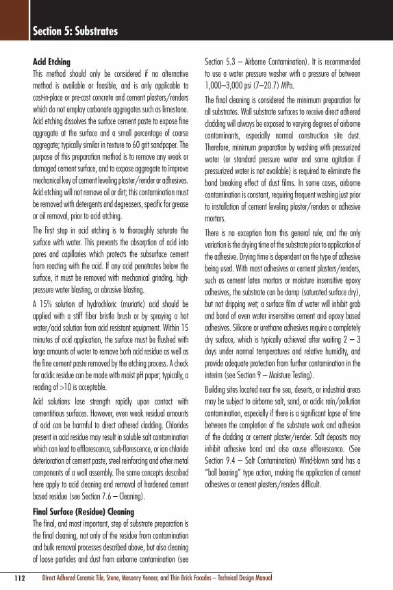
112 Direct Adhered Ceramic Tile, Stone, Masonry Veneer, and Thin Brick Facades – Technical Design Manual
Section 5: Substrates
Section 5.3 – Airborne Contamination). It is recommended to use a water pressure washer with a pressure of between 1,000–3,000 psi (7–20.7) MPa.
The final cleaning is considered the minimum preparation for all substrates. Wall substrate surfaces to receive direct adhered cladding will always be exposed to varying degrees of airborne contaminants, especially normal construction site dust. Therefore, minimum preparation by washing with pressurized water (or standard pressure water and some agitation if pressurized water is not available) is required to eliminate the bond breaking effect of dust films. In some cases, airborne contamination is constant, requiring frequent washing just prior to installation of cement leveling plaster/renders or adhesive mortars.
There is no exception from this general rule; and the only variation is the drying time of the substrate prior to application of the adhesive. Drying time is dependent on the type of adhesive being used. With most adhesives or cement plasters/renders, such as cement latex mortars or moisture insensitive epoxy adhesives, the substrate can be damp (saturated surface dry), but not dripping wet; a surface film of water will inhibit grab and bond of even water insensitive cement and epoxy based adhesives. Silicone or urethane adhesives require a completely dry surface, which is typically achieved after waiting 2 – 3 days under normal temperatures and relative humidity, and provide adequate protection from further contamination in the interim (see Section 9 – Moisture Testing).
Building sites located near the sea, deserts, or industrial areas may be subject to airborne salt, sand, or acidic rain/pollution contamination, especially if there is a significant lapse of time between the completion of the substrate work and adhesion of the cladding or cement plaster/render. Salt deposits may inhibit adhesive bond and also cause efflorescence. (See Section 9.4 – Salt Contamination) Wind-blown sand has a “ball bearing” type action, making the application of cement adhesives or cement plasters/renders difficult.
Acid EtchingThis method should only be considered if no alternative method is available or feasible, and is only applicable to cast-in-place or pre-cast concrete and cement plasters/renders which do not employ carbonate aggregates such as limestone. Acid etching dissolves the surface cement paste to expose fine aggregate at the surface and a small percentage of coarse aggregate; typically similar in texture to 60 grit sandpaper. The purpose of this preparation method is to remove any weak or damaged cement surface, and to expose aggregate to improve mechanical key of cement leveling plaster/render or adhesives. Acid etching will not remove oil or dirt; this contamination must be removed with detergents and degreasers, specific for grease or oil removal, prior to acid etching.
The first step in acid etching is to thoroughly saturate the surface with water. This prevents the absorption of acid into pores and capillaries which protects the subsurface cement from reacting with the acid. If any acid penetrates below the surface, it must be removed with mechanical grinding, high-pressure water blasting, or abrasive blasting.
A 15% solution of hydrochloric (muriatic) acid should be applied with a stiff fiber bristle brush or by spraying a hot water/acid solution from acid resistant equipment. Within 15 minutes of acid application, the surface must be flushed with large amounts of water to remove both acid residue as well as the fine cement paste removed by the etching process. A check for acidic residue can be made with moist pH paper; typically, a reading of >10 is acceptable.
Acid solutions lose strength rapidly upon contact with cementitious surfaces. However, even weak residual amounts of acid can be harmful to direct adhered cladding. Chlorides present in acid residue may result in soluble salt contamination which can lead to efflorescence, sub-florescence, or ion chloride deterioration of cement paste, steel reinforcing and other metal components of a wall assembly. The same concepts described here apply to acid cleaning and removal of hardened cement based residue (see Section 7.6 – Cleaning).
Final Surface (Residue) CleaningThe final, and most important, step of substrate preparation is the final cleaning, not only of the residue from contamination and bulk removal processes described above, but also cleaning of loose particles and dust from airborne contamination (see
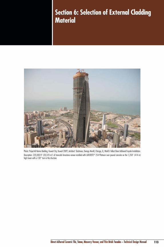
113Direct Adhered Ceramic Tile, Stone, Masonry Veneer, and Thin Brick Facades – Technical Design Manual
Section 6: Selection of External Cladding Material
113Direct Adhered Ceramic Tile, Stone, Masonry Veneer, and Thin Brick Facades – Technical Design Manual
Photo: Project-Al Hamra Building, Kuwait City, Kuwait 2009, Architect: Skidmore, Owings Merrill, Chicago, IL; World’s Tallest Direct Adhered Façade Installation.Description: 220,000 ft2 (20,370 m2) of trencadis limestone veneer installed with LATICRETE® 254 Platinum over poured concrete on the 1,350' (414 m) high tower with a 130° turn in the structure.

114 Direct Adhered Ceramic Tile, Stone, Masonry Veneer, and Thin Brick Facades – Technical Design Manual
Section 6: Selection of External Cladding Material
6.1 CRITERIA FOR SELECTION OF CERAMIC TILE, STONE, ADHERED MASONRY VENEER, AND THIN BRICK MASONRYThe exterior cladding of a building is exposed to some of the harshest and most extreme conditions of any system in a building. While you will see that many types of ceramic tile, stone, masonry veneer, and thin brick are generally suitable for exterior, direct adhered wall assemblies, there is no standard formula or recommendation for the selection of exterior cladding. Selection must be made by an assessment of the individual cladding material’s functional and aesthetic characteristics.
A discussion of the aesthetic merits of different cladding materials is highly subjective and is beyond the technical focus of this manual. This section will focus primarily on the functional criteria necessary to determine whether a cladding material’s physical characteristics satisfy the performance requirements of a building facade’s unique design and location. While every building is unique, the following are criteria that can be used to determine general functional suitability of ceramic tile, stone, masonry veneer, and thin brick cladding materials:
Selection Criteria for Cladding Material Performancen Low water absorption raten Thermal movement compatibility with adhesive and
substraten High breaking strengthn Chemical resistancen Thermal movement and shock resistancen Adhesive compatibilityn Dimensional stability (heat and moisture insensitivity,
moisture expansion)n Frost resistance (cold climates)n Dimension and surface quality/tolerancen Crazing resistance of glazing
Stone, while being the oldest building material known to man, can also be one of the most difficult of all building materials to properly evaluate, select and specify. Every stone product is unique, having its own physical properties and performance capabilities. The selection of a proper stone material involves extensive and objective evaluation of both the stone material and the application in which it is required to perform. ASTM
C1528 “Standard Guide for Selection of Dimension Stone for Exterior Use” should be used to help determine suitability and acceptability of a particular stone for exterior façade use.
Low Water Absorption RateThe rate of water absorption of a cladding material is one of the most significant physical characteristics. This characteristic provides an indication of material structure and overall performance, and has significant influence on many other physical characteristics that are desirable for an exterior cladding material. Water absorption, also known as porosity, is defined as a measure of the amount of water that can be absorbed through pores of a material, and it is measured as a percentage difference between tested dry and wet (saturated) weight of the material.
As a general rule, the lower the water absorption rate of the cladding material, the greater the frost, stain, chemical, and abrasion resistance, along with improved breaking strength of the cladding material. These are all highly desirable qualities for an exterior cladding material.
Thermal Movement CompatibilityThe cladding material’s rate of expansion and contraction due to temperature changes must be relatively compatible with the substrate and other building elements within the installation assembly. Significant differences in thermal movement characteristics could cause excessive stress in the adhesive interface and lead to delamination or bond failure (see Section 9). Minor differences in thermal compatibility are usually acceptable, and the selection of flexible (low modulus) adhesives (see Section 7) plays a critical role in distributing minor differential movement. Adhesive mortars which meet the ISO or EN classification of C2S1 or better classification provide deformability (flexibility) and can perform well in exterior façade installations of ceramic tile, stone, masonry veneer, or thin brick.
Accurate prediction of thermal behavior is extremely complex. Consideration must be made for the rate and fluctuation of temperatures, the thermal gradients and the lag that exists in an often massive composite wall assembly. Figure 6.1.1 shows typical rates of thermal movement of materials commonly employed in a direct adhered facade assembly.

115Direct Adhered Ceramic Tile, Stone, Masonry Veneer, and Thin Brick Facades – Technical Design Manual
Section 6: Selection of External Cladding Material
MATERIAL COEFFCIENT OF THERMAL EXPANSION (10-6 mm/mm/C°)
Ceramic Tile 4 – 8
Granite 8 – 10
Marble 4 – 7
Brick 5 – 8
Cement Mortar 10 – 13
Concrete 10 – 13
Lightweight Concrete 8 – 12
Gypsum 18 – 21
Concrete Block (CMU) 6 – 12
Cellular Concrete Block 8 – 12
Steel 10 – 18
Aluminum 24
Copper 17
Polystyrene Plastic 15 – 45
Glass 5 – 8
Wood – Parallel Fiber 4 – 6
Wood – Perpendicular Fiber 30 – 70
Figure 6.1.1 – Coefficient of linear thermal expansion for various materials. Bold indicates common exterior façade veneer cladding finishes.
High Breaking Strength (Modulus of Rupture)The breaking strength resistance of a cladding material is important primarily due to the type of handling that is necessary for installation on a building facade. Once adhered in place to a composite wall system, a direct adhered cladding material has up to ten times the breaking strength resistance compared to the uninstalled cladding material alone.
The natural fragility and cleavage of many quarried stone products makes them particularly susceptible to breakage. Because the direct adhered method of installation allows thin sections of stone to be used, a careful assessment of breaking strength relative to the stone’s thickness and dimension (facial area) will eliminate unforeseen high waste factors and increased costs. The standard to determine the modulus of rupture for stone is ASTM C99 “Standard Test Method for Modulus of Rupture of Dimension Stone”.
Chemical ResistanceCladding materials must have good chemical resistance to prevent deterioration from airborne pollutants (especially acid rain) and chemicals that may be used in cleaning/maintenance, not only of the cladding material, but also other components of the wall (e.g. windows, awnings, etc…). Use ASTM C1515 “Standard Guide for Cleaning of Exterior Dimension Stone, Vertical and Horizontal Surfaces, New or Existing” to help determine the most suitable cleaning regimen for exterior stone facades.
Thermal Shock ResistanceBuilding facades are typically exposed to a broad range and rate of change of temperatures (see Section 6.5 Temperature and Color Considerations). There is a difference between thermal shock and thermal movement. Thermal shock refers to the rate and range of temperature fluctuation within short periods of time. A façade, with a southern or western solar orientation, in a hot climate which is exposed to a sudden cool rainstorm can send the temperature of a cladding material plunging within a matter of minutes.
Compatibility with AdhesiveThe suitability of adhesives for the proposed application must be evaluated taking into consideration the criteria listed in Section 7 – Selection of Adhesives. Part of that process is evaluating an adhesive’s compatibility with the cladding material’s composition, surface texture, and other physical characteristics, such as translucency. For example, lighter colored marble stones are translucent, and the reflection and transmission of the color of the underlying adhesive can have significant aesthetic consequences. Similarly, adhesives should not stain the cladding material, or contribute indirectly to staining by solubility or reaction of chemicals with water. For example, the plasticizers of certain silicone or urethane adhesives may be absorbed by stone causing permanent discoloration. Polymers of some latex additives not intended for exterior applications could be soluble in water and cause staining problems. Another example is calcium chloride accelerant that may be used in some latex cement adhesive mortars. This additive may contribute soluble salts and result in efflorescence after repeated water infiltration to the adhesive layer. Always conduct a test area under actual job site conditions and exposures to determine suitability and acceptability of the adhesive and cladding material.

116 Direct Adhered Ceramic Tile, Stone, Masonry Veneer, and Thin Brick Facades – Technical Design Manual
Section 6: Selection of External Cladding Material
Depending on the texture and porosity of the cladding material’s bonding surface, certain adhesives may require more, or less, dwell time in order to allow absorption of adhesive, a process known as “wetting out” a surface.
Dimensional Stability (Moisture and Heat Sensitivity)Generally, the dense and compact nature of a low absorption cladding material will impart good dimensional stability to that material. However, there are certain exceptions where low absorption is not necessarily an indicator of dimensional stability. Certain types of marble and agglomerates, while water absorption rate is favorable, exhibit internal crystal growth when exposed to moisture and can warp, spall or deteriorate rapidly when exposed to the weather on a façade (see Section 6.5, Moisture Sensitivity). The resins used in many agglomerates may have a significantly higher rate of thermal expansion when exposed to heat of the sun. Similarly, clay brick undergoes permanent volume expansion after prolonged exposure to moisture (see Section 6.5).
Frost ResistanceGenerally, frost resistance is a function of water absorption characteristics. Any cladding material with water absorption lower than 3% is considered frost (freeze) resistant. However, the pore structure of brick and certain stone will allow water absorption greater than 3% and still be considered frost resistant. Nonetheless, a high water absorption rate will still reduce durability and resistance to weathering in general. Polishing of a stone surface can reduce surface porosity and increase resistance to weathering. To determine the absorption rate of stone use ASTM C97 “Standard Test Methods for Absorption and Bulk Specific Gravity of Dimension Stone”.
Dimension and Surface QualityCeramic tile and thin brick masonry are manufactured materials, and therefore, dimensional and surface tolerances required for direct adhesion can be assured by selecting materials in compliance with established standards. For ceramic tile the applicable standards would be ISO 10545-2 “Ceramic tiles -- Determination of Dimensions and Surface Quality” and ANSI A137.1 “American National Standard Specifications for Ceramic Tile”, which incorporates ASTM C499 “Standard Test Method for Facial Dimensions and Thickness of Flat, Rectangular Ceramic Wall and Floor Tile.” For thin brick, ASTM
C1088 “Standard Specification for Thin Veneer Brick Units Made From Clay or Shale” governs dimension and surface quality.
Stone is generally fabricated to specification for a variety of methods of installation. There are uniform standards for dimension and surface quality of stone tiles or slabs listed for individual varieties of stone in Section 6.3.
It is recommended that the back side of an external cladding material have a key-back or dovetail configuration in order to develop a mechanical lock with the bonding adhesive (or concrete in the case of negative cast pre-cast concrete panels). Grooved or rib-back cladding materials will also improve the factor of safety in the event of adhesive bond failure. Ceramic tile manufacturers currently offer this technology, primarily with ceramic tile manufactured by the extruded method. They are expanding this concept to thinner and larger module tiles manufactured with the dust pressed method specifically for facade applications.
In Japan, standards require that ceramic tile used as external facade cladding have a key-back or ribbed configuration. The Japanese standard requires tile to have “feet” with a depth of more than 1/16" (0.5 mm) for 1" (25 mm) square tiles, over 3/32" (0.7 mm) for tiles 1" – 4-1/4" x 2-1/4" (25 –108 mm x 60 mm), and 3/16" (1.5 mm) for tiles 2-1/2" x 4-1/4" (60 x 108 mm) or larger. Japanese standards also prohibit the use of back-mounted mosaic ceramic tile and allow only paper face mounted mosaic tile for external cladding. Most other countries currently do not require cladding material to have a key-back configuration.
Key-back configurations for thin brick are widely available. Providing grooved configurations on stone is not very economical. However, new mesh-type backings applied to stone to strengthen thin sections also show promise in providing additional safety factor for adhesive applications.
6.2 CERAMIC TILEThe beauty, durability, and functional qualities of ceramic tile make it one of the most suitable finishes for cladding the facades of buildings. While some other cladding materials may possess these qualities, none are as versatile and affordable as ceramic tile. As you might expect, there is an extraordinary number of different types and sizes of ceramic tile, yet only

117Direct Adhered Ceramic Tile, Stone, Masonry Veneer, and Thin Brick Facades – Technical Design Manual
Section 6: Selection of External Cladding Material
some types of ceramic tile have the physical characteristics required to be directly adhered to exterior wall assemblies.
Ceramic tile for external cladding can range in size from 1" x 1" (25 x 25 mm) nominal mosaics up to 48" x 48" (800 x 1200 mm) and 36" x 36" (900 x 900 mm) nominal porcelain stoneware tile. Check with local building code to determine the allowable dimensions and weight of a direct adhered cladding material prior to specifying.
The raw materials for ceramic tile are a mixture of clay (to give plasticity), quartz sand (to give structural strength and act as an economical filler), and carbonates or feldspars (to provide fluxing/fusing action). The raw materials are ground down while water is added. The raw material for ceramic tiles used for external cladding are typically dried to a moisture content of 4–7% and shaped by the dust pressed method at pressures of 4,270 psi (300 kg/cm2) or higher. Some tiles used for external cladding may be formed by the extrusion method, where clay with a moisture content of 15–20% is extruded through a die of desired shape.
Glazes are applied to the face of the tile, typically before the firing process begins.
Glazes are formed from sand, kaolinitic clay, prepared glasses (frit), and oxide based pigments to provide color. After forming, the raw tile or “bisque” is dried to remove excess water and fired in kilns operating at temperatures of 1,750–2,200°F (954–1,200°C). This results in vitrification, or fusing, of the clay and fillers which produce a tile product that is dense and non-porous. As mentioned previously, low water absorption is a key physical characteristic of external cladding materials and has significant influence on other physical characteristics.
Characteristics of Ceramic Tile for External CladdingIn order to select the most suitable type of ceramic tile for an external facade, and to understand the technical considerations for adhesive compatibility and installation, the specifier must have a general understanding of the classifications and physical properties of ceramic tile.
Water Absorption (Body of Tile)The definition of water absorption is the measure of the amount of water that can be absorbed through pores of the ceramic tile.
This characteristic is an indication of a ceramic tiles’ structure and overall performance. Water absorption is measured by ASTM C373 “Standard Test Method for Water Absorption, Bulk Density, Apparent Porosity, and Apparent Specific Gravity of Fired Whiteware Products” and ISO 10545-3 “Ceramic Tiles – Determination of Water Absorption, Apparent Porosity, Apparent Relative Density, and Bulk Density” as a percentage difference between dry and wet weight of tile. The water absorption characteristics of ceramic tile have significant influence on many other physical characteristics that are important to proper performance as an external cladding material. Water absorption of ceramic tile for external cladding should be 3% or less for climates that experience freezing temperatures, and 6% or less for all other climates.
One important note on water absorption; porcelain ceramic tile is the most popular choice for external cladding. It is one of the most durable and beautiful cladding materials available. However, precision manufacturing processes now allow porcelain tiles with under 0.05% (negligible) water absorption rates. While this creates an extremely durable cladding, it makes adhesion with traditional portland cement adhesives extremely difficult, because these types of adhesives rely on absorption of cement paste to provide mechanical locking of crystals within the pore structure of the tile surface. Porcelain tiles require the improved performance capabilities of latex fortified cement (e.g. LATICRETE® 254 Platinum) or epoxy adhesives (e.g. LATAPOXY® 310 Stone Adhesive or LATAPOXY 310 Rapid Stone Adhesive) to develop the high bond strength and flexibility required for façade applications.
CLASSIFICATION OF CERAMIC TILE BY WATER ABSORPTION ISO (International Standards Organization) CEN (European Norms)
Group I Group II Group III Group IV
Absorption ≤3% 3 - ≤6% 6 - ≤10% >10%
Group A Extrusion
Group A1 Group AIIa Group AIIb Group AIII
Group B Dust-
Pressed
Group B1 Group BIIa Group BIIb Group BIII
Figure 6.2.1 – Classification of ceramic tile by water absorption (ISO and EN Standards).

118 Direct Adhered Ceramic Tile, Stone, Masonry Veneer, and Thin Brick Facades – Technical Design Manual
Section 6: Selection of External Cladding Material
TILE CLASS AND CORRESPONDING WATER ABSORPTION RANGES
ANSI 137.1 Standards
Forming Method
Impervious (Porcelain) WA ≤0.5%
Vitreous >0.5% WA ≤3.0%
Semi-Vitreous >3.0% WA ≤7.0%
Non-Vitreous >7.0% WA ≤20.0%
Pressed P1 P2 P3 P4
Extruded E1 E2 E3 E4
Other O1 O2 O3 O4
Figure 6.2.2 – Classification of ceramic tile by water absorption (ANSI standards)12.
As shown in Figure 6.2.2, the tiles suitable for use on exterior facades would be classified as P1, P2, E1, and E2. O1 and O2 may also be suitable if the manufacturer specifically states that the particular tile is suitable for exterior façade installations.
Thermal ShockThe definition of thermal shock is internal stress created when a tile undergoes rapid changes in temperature within short periods of time. The significance of this characteristic is that it provides an indication of good performance in exterior applications where there are constant cycles of thermal shock. Thermal shock is measured by ASTM C484 “Standard Test Method for Thermal Shock Resistance of Glazed Ceramic Tile” and ISO 10545-9 “Ceramic Tiles – Determination of Resistance to Thermal Shock” where there are no defects after 10 cycles of sudden temperature change to and from 60 – 220°F (16 – 104°C).
Thermal Expansion/ContractionThe definition of thermal movement is the amount of expansion or contraction a ceramic tile undergoes from temperature changes. The significance of this characteristic is that tile expands when the temperature increases, and contracts when the temperature decreases. The measurement of a tile’s thermal coefficient of expansion provides the designer with the information necessary to determine compatibility with the substrate and adhesive materials, to calculate movement differentials, and for the design of movement (expansion) joints. Thermal expansion is measured by ASTM C372 “Standard Test Method for Linear Thermal Expansion of Porcelain Enamel and Glaze Frits and Fired Ceramic Whiteware Products by the Dilatometer Method”, ISO 10545-8 “Ceramic Tiles – Determination of Linear Thermal Expansion” and is expressed as the linear coefficient of thermal expansion in units of in/in/°F (mm/m/°C).
Frost ResistanceThe definition of frost resistance is the ability of the ceramic tile to resist the expansive action of freezing water. This characteristic is dependent on the tile absorption rate and the shape and size of pores. It is measured by ASTM C1026 “Standard Test Method for Measuring the Resistance of Ceramic Tile to Freeze-Thaw Cycling” and ISO 10545-12 “Ceramic Tiles – Determination of Frost Resistance”.
Breaking Strength (Modulus of Rupture)Breaking strength primarily determines resistance to the handling and installation process. This characteristic is a measure of the tile material and not the tile itself. For example, if you compared two tiles of the same material with one being twice as thick, both would have the same unit breaking strength, but the thinner tile would require 75% less load or force to break. Impact resistance in service (fully adhered) is approximately 10 times greater than the minimum standard. It is measured by ASTM C648 “Standard Test Method for Breaking Strength of Ceramic Tile” and ISO 10545-4 “Ceramic Tiles – Determination of Modulus of Rupture and Breaking Strength” which requires a minimum strength for all floor tile of 250 psi (1.7 MPa); there are no special breaking strength provisions for ceramic tile intended for use as external cladding.
Moisture ExpansionMoisture expansion is the dimensional change of ceramic tile as a result of exposure to moisture. This is a significant characteristic for tile used as exterior cladding because moisture expansion of clay is irreversible. It is measured by ASTM C370 “Standard Test Method for Moisture Expansion of Fired Whiteware Products” and ISO 10545-10 “Ceramic Tiles – Determination of Moisture Expansion”. Moisture expansion is directly proportional to absorption; the lower the absorption, the greater resistance to moisture expansion and vice versa.
Chemical and Stain ResistanceThe definition of chemical resistance is the behavior of tile to resist damage when it comes into contact with aggressive chemicals. Chemical resistance actually measures deterioration caused by two mechanisms; 1) chemical reaction resulting in alteration of tile, and; 2) penetration of a chemical or stain below the tile surface, and difficulty of removal resulting in long term deterioration or effect on materials in contact

119Direct Adhered Ceramic Tile, Stone, Masonry Veneer, and Thin Brick Facades – Technical Design Manual
Section 6: Selection of External Cladding Material
adhesive installation of a particular stone, the specifier must have a general understanding of the classifications and physical properties of the different categories of stone.
Types of Natural Stone – Geologic ClassificationNatural stone is classified geologically in three categories, also known as the “Three Great Classes” of stone:
Types of Natural StoneGeologic Classification
n Igneous – Solidified rock from molten state types – granite
n Sedimentary – Cementing, consolidation and crystallization of chemical solutions and biological deposits types – limestone, sandstone
n Metamorphic – Change or alteration of solidified rock by heat, pressure, or intrusion of other rock types – marble, slate, quartzite
Types and Characteristics of Building StoneGranite – Geologic and Commercial ClassificationGranite is classified as an igneous stone, and has a primary mineral composition of feldspar and quartz. Black granite, also known as trap rock, has a completely different mineral composition than granite, but is commercially classified as a granite. Black granite actually has a mineral composition of hornblende and biotite and is not necessarily black in color. Granite should meet the requirements as stated in ASTM C615 “Standard Specification for Granite Dimension Stone” prior to consideration as an exterior façade veneer.
Some varieties of granite contain trace minerals which can cause discoloration or exfoliation after prolonged exposure to the weather.
Granite – CharacteristicsGranite has a distinct crystalline appearance and is extremely hard, dense, and resistant to scratches and acids. It is a very suitable stone for direct adhered exterior walls, especially because the density and hardness of granite impart stability and high breaking strength resistance (minimum requirement 1,500 psi [10.3 MPa]) when fabricated in thin slabs or tiles that are necessary for cost effective installation using the direct adhered method. Laboratory research has also demonstrated that most granites fabricated in sections as thin as 5/16 – 7/16" (8–11 mm) have low moisture sensitivity
with the surface, such as dirt collection. Chemical and stain resistance is measured by ISO 10545-13 “Ceramic Tiles – Determination of Chemical Resistance” by determining visual deterioration after exposure to standard chemical solutions (cleaning detergents, bleach, lactic and sulfuric acid, potassium hydroxide/alkali). The importance of this characteristic for external cladding is the resistance to deterioration and staining caused by atmospheric pollution (especially dirt and acid rain), and the resistance to cleaning chemicals necessary for normal maintenance of a facade. Methods and materials for cleaning ceramic tile facades can be determined using ASTM D5343 “Standard Guide for Evaluating Cleaning Performance of Ceramic Tile Cleaners”.
6.3 STONE AND AGGLOMERATESThere are a wide variety of stones used in building construction, both natural and synthetic, which are suitable as direct adhered cladding. However, determining suitability of stone as a direct adhered external cladding material requires more careful analysis than manufactured materials like ceramic tile, masonry veneer or thin brick because it is a heterogeneous natural material, and even different pieces of the same type of stone will exhibit varying properties.
Aside from aesthetic characteristics of color and texture, which again are not the focus of this manual, the porosity of stone is one of the key physical characteristics which determines the durability and suitability of the stone as a direct adhered external cladding material. The effects of moisture on direct adhered stone are varied. Moisture absorbed in a stone may be heated by solar radiation or frozen by cold temperatures which can exert pressure in excess of the tensile strength of the stone (water increases 9% in volume when frozen!). Moisture can also act as a vehicle for transport of soluble salts and contamination from other surfaces.
Rupture or breaking strength of stone is also an important characteristic of stone used in direct adhered exterior walls. Good breaking strength is required to resist reflection of thermal or moisture induced movement in the underlying wall assembly structure, and to resist potential breakage of thin stone during handling and installation.
In order to select the most suitable type of stone for an application, and understand the technical requirements for

120 Direct Adhered Ceramic Tile, Stone, Masonry Veneer, and Thin Brick Facades – Technical Design Manual
Section 6: Selection of External Cladding Material
Limestone – Geologic and Commercial ClassificationLimestone is classified as a sedimentary stone with a primary mineral composition of calcite and dolomite. Limestone is geologically categorized as either oolitic or dolomitic, and is commercially categorized as a building stone according to ASTM C 568 “Standard Specification for Limestone Dimension Stone” by density properties: low density-category I, medium density-category II, and high density category III. High density limestone (Category III) has an absorption rate of <3% and a minimum Modulus of Rupture of 1,000 psi (6.9 MPa), and is considered the best choice for exterior facades, especially in colder climates (see characteristics below). Similar to other building stones, limestone is further differentiated by color (white, cream, buff or rose) and geographic origin.
Special varieties of limestone include travertine, a limestone which is formed by the precipitation of minerals in hot springs. Travertine, while geologically classified as a limestone, is commercially classified as a marble (see marble) because it can be polished. Onyx is a type of translucent limestone which is formed by precipitation of calcite in cold water found in limestone caves. The requirements for travertine can be found in ASTM C1527 “Standard Specification for Travertine Dimension Stone”, and are quite different from the requirements for limestone, as stated in ASTM C568, despite being in the limestone family.
Limestone – CharacteristicsLimestone is characterized by the relatively loose cementing or consolidation of the minerals calcite and dolomite originating from biological deposits such as shells and sediments. As a general rule, the lower density limestone materials (as classified above) have less desirable physical characteristics for exterior facades (especially in colder climates) such as a higher water absorption rate (7.5 – 12% by weight). Conversely, the lower density limestone may possess better adhesive characteristics, especially with lower cost cement based adhesives. High density limestone has low absorption rates (<3% by weight) which imparts good freeze-thaw resistance and moisture stability.
and undergo minimum distortion or hysteresis growth (see Section 6.5) when adhered with water or latex based cement adhesive mortars.
Granites used in building construction, especially exterior walls, should have a maximum absorption rate of 0.40% by weight according to ASTM standards. The low absorption rate of most building granite requires that cement adhesive mortars, which rely on absorption of cement paste and subsequent locking effect of crystal growth into the stone pores, have the advantages of latex (e.g. LATICRETE® 254 Platinum) or, use spot bond epoxy adhesives (e.g. LATAPOXY® 310 Stone Adhesive) to insure proper adhesion. A latex fortified cement based adhesive will retard the evaporation of moisture needed, thus allowing maximum absorption of cement paste. This allows the cement crystals to grow which produces a locking effect, and also imparts pure adhesive bond. Due to the translucency of minerals in some varieties, together with the thin widths typically used with the direct adhered method, some granites can darken temporarily from exposure to moisture (including the moisture in adhesive mortars). Granite may also darken permanently from reflection of dark or inconsistent coverage of underlying adhesives, or even darken or stain permanently from absorption of chemicals, such as plasticizers which can be found in some (silicone) sealants (see Section 4 – Sealants and Section 9 – Fluid Migration).
In selecting a thin granite for direct adhesion, it is recommended to avoid large grained granites, relative to thickness; grain size should be less than 1/10 the stone thickness to maintain structural integrity of the vitrification between grain boundaries. While finishes of stone are primarily an aesthetic consideration, it should be noted that a thermal finish, common on granite, can induce thermal shock damage to the first 1/8" (3 mm) depth of the stone face, and should be taken into account by deducting this layer when calculating thickness specifications. Other common finishes for external cladding are polished, honed, sandblasted and bush hammered.
Commercially, granite is available in hundreds of varieties, differentiated primarily by color (a function of the mineral composition) and geographic origin.

121Direct Adhered Ceramic Tile, Stone, Masonry Veneer, and Thin Brick Facades – Technical Design Manual
Section 6: Selection of External Cladding Material
Specification for Serpentine Dimension Stone” provides requirements for the conformance of serpentine stone while the previously mentioned ASTM C1527 covers travertine.
Marble Classificationn Class I – Calcite n Class II – Dolomiten Class III – Serpentinen Class IV – Travertine
Stone industry organizations such as the Marble Institute of America (MIA) further classify marble according to soundness:
Marble – The Four Groups of Marble Soundness Classification
n Group A – Sound stone with uniform and favorable working qualities containing no geological flaws or voids.
n Group B – Stone similar to group A; may have some natural holes or voids which are typically filled by the marble craftsman
n Group C – Stone with variations in working qualities, containing geological flaws, voids, veins and lines of separation.
n Group D – Stone similar to Group C but contain a higher proportion of natural faults, maximum variation in working qualities and requiring extra finishing.
While fabrication classifications are not necessarily an indication of the physical properties or durability of stone, it is generally recommended that only Group A and Group B marble are suitable for use as external cladding, especially due to the thinner sections typical with the direct adhered method of installation. However, one of the advantages of the direct adhesion of stone is that the entire surface of the stone is adhered. Direct adhesion allows stone, which may normally be too fragile for mechanical anchorage, to be considered for direct adhesion, as long as the marble can be fabricated and handled safely prior to adhesive installation. The marble must also prove to have weathering durability so as to prevent spalling or exfoliation, even if fully adhered.
Sandstone – Geologic and Commercial ClassificationSandstone is geologically classified as a sedimentary stone with a primary mineral composition of quartz. Sandstone is commercially categorized by mineral content (the percentage of quartz) according to the following three categories; sandstone (60%), quartzitic sandstone (90%), and quartzite (95%).
Sandstones are further classified by varieties according to their color and geographic origin. For example, bluestone is a dense, fine grained quartzite, and brownstone, a loose, rough textured sandstone.
Sandstone – CharacteristicsSandstones are typically characterized by a loose or rough texture. Standard sandstones may have water absorption rates as high as 20% by weight, while quartzite, a more homogeneous composition of mainly quartz cemented with silica, has absorption <1% by weight. Sandstone (< 60% quartz) is typically sensitive to weathering and cut relative to bedding planes.
Marble – Geologic and Commercial ClassificationMarble is geologically classified as a metamorphic stone with a primary mineral composition of calcite and dolomite. Geologically, marble is actually a limestone that has been re-crystallized by heat, pressure, and intrusion of other minerals (thus the term “metamorphic”). The term “marble” is a commercial category of natural stone. Geologically, marble is a metamorphic limestone of sufficient hardness capable of taking a polish. ASTM C503 “Standard Specification for Marble Dimension Stone” provides a guideline for material characteristics and physical requirements of marble.
Commercially, there are over 8,000 varieties of marble and these are based on mineral content, color and geographic origin. According to ASTM C503 “Standard Specification for Marble Dimension Stone”, there are two classifications of marble building stone:
The percentage of magnesium carbonate in marble generally determines its strength, color, texture and variety. Calcite marbles have <5% of magnesium carbonate, and dolomite marbles have >40% magnesium carbonate. Travertine is geologically a limestone, and serpentine is geologically an igneous stone, both capable of taking a polish, and therefore is commercially classified as a marble. ASTM C1526 “Standard

122 Direct Adhered Ceramic Tile, Stone, Masonry Veneer, and Thin Brick Facades – Technical Design Manual
Section 6: Selection of External Cladding Material
In some agglomerate products, the characteristics of the binder may have a dominant effect on the behavior and performance of the product. Polyester resins have a high thermal coefficient of expansion and can present problems of significant differential movement when installed on a facade.
Agglomerate Stone – CharacteristicsThere are hundreds of proprietary agglomerate products on the market, each with its own physical characteristics dependent on the type of stone fragments or aggregates, type of binder, and percentage of each material. The most popular agglomerate tiles typically consist of natural stone pieces in a 4–8% polyester resin binder. It is important to verify the suitability of agglomerates for exterior applications on building facades due to the instability of some resins and stone pieces when exposed to moisture, extreme temperature changes, or freeze-thaw cycles (see Section 6.5). Please consult the agglomerate stone manufacturer for suitability information.
6.4 ADHERED MANUFACTURED MASONRY VENEERManufactured masonry veneer materials are lightweight, architectural, non-load bearing products which are manufactured by wet cast blending cementitious material, aggregate, iron oxide pigments, and admixtures to simulate the appearance of natural stone. These products come in a wide variety of finishes including stacked stone, river rock, rubble, ashlar, and more… In fact, some manufactured veneer products pour their proprietary cement mixture into molds created from actual natural stone to create a very natural looking product.
Adhered Manufactured Masonry Veneer SelectionAdhered manufactured stone masonry veneer (AMSMV) is a lightweight man made concrete masonry product which is usually cast into random sizes, in a variety of colors with a natural undressed quarried or cleft stone finish. Oftentimes, these types of materials are referred to as simulated stone or adhered veneer. AMSMV is generally applied as a residential or lightweight commercial masonry adhered veneer to exterior and interior walls, columns, landscape structures, and other vertical areas and structures suitable to receive lightweight adhered units. However, AMSMV is not to be confused with cast stone products. Cast stone products can be used to add to the load bearing capacity of a masonry wall, thereby becoming part of a composite wall system rather than being adhered to it.
Marble – CharacteristicsMarble is a relatively soft stone, which is easily scratched, or, etched by acidic materials. Marble is not particularly durable as an external cladding in harsh climates.
Slate – Geologic and Commercial ClassificationSlate is geologically classified as a metamorphic stone with a primary mineral composition of quartz and mica. According to ASTM C629 “Standard Specification for Slate Dimension Stone”, slate is commercially classified as either type I – Interior, or type II – Exterior. Slate is available in a variety of colors and from numerous geographic origins.
Slate – CharacteristicsSlate is characterized by a sheet-like structure with cleavage parallel to the grain. Slate is normally fabricated with a natural cleft surface, although some slates can be sanded smooth.
There are a wide variety of slates, and even some type II slates do not have suitable characteristics for use in direct adhered exterior walls. A relatively “young” slate has a higher percentage of mica and lower density. This characteristic results in easy parallel cleavage and susceptibility to cohesive shear failure when exposed to shear forces common in direct adhered wall assemblies. The high percentage of mica also results in a friable, dust-like surface which prevents good adhesion to the body of the slate, even after proper washing and preparation. Conversely, “old” slates have a more dense, compact structure, and are suitable for direct adhesion. Only laboratory or field shear bond and tensile strength testing can ascertain suitability of slates for direct exterior adhesion.
Agglomerate Stones – ClassificationAgglomerate is a term used to describe a man-made stone slab or tile product that typically consists of stone pieces and/or aggregates held together in a synthetic binder such as a polyester or epoxy resin. While there is no geologic classification for agglomerates, many of these products have physical characteristics similar to the type of stone pieces used in the matrix, and are often commercially classified as granites or marbles. The performance requirements of agglomerate stone can be measured using EN14617 “Agglomerated Stone – Test Methods – Part 1 – 16 (less 2 and 7)”.

123Direct Adhered Ceramic Tile, Stone, Masonry Veneer, and Thin Brick Facades – Technical Design Manual
Section 6: Selection of External Cladding Material
building code) is required to prevent cracking of the adhered veneer. Movement joints are required for any adhered cladding system and the Tile Council of North America Handbook for Ceramic, Glass, and Stone Tile Installation EJ-171 may be used to provide a guideline for movement joint placement. It is the responsibility of the design team to designate the construction, placement and composition of movement joints within the project drawings.
The requirements for installation of AMSMV are generally the same as for the installation of tile or stone. The substrate must be;
1. Sound, rigid and conform to good design/engineering practices;
2. Systems, including the framing system and panels, over which tile or stone will be installed shall be in conformance with the International Residential Code (IRC) for residential applications, the International Building Code (IBC) for commercial applications, or applicable building codes. The project design should include the intended use and necessary allowances for the expected live load, concentrated load, impact load, and dead load including the weight of the finish and installation materials. In addition to deflection considerations, above-ground installations are inherently more susceptible to vibration. Consult grout, mortar, and membrane manufacturer to determine appropriate installation materials for above-ground installations. A crack isolation membrane and higher quality setting materials can increase the performance capabilities of above-ground applications. However, the upgraded materials cannot mitigate structural deficiencies including floors not meeting code requirements and/or over loading or other abuse of the installation in excess of design parameters. Maximum allowable floor member live load and concentrated load deflection shall not exceed L/360 for tile, or, L/480 for stone, where L is the clear span length of the supporting member per applicable building code;
3. Clean and free of dust, dirt, oil, grease, sealers, curing compounds, laitance, efflorescence, form oil, loose plaster, paint, and scale;
At the time of the updating of this manual, work continues on an ASTM standard specifications for AMSMV. ASTM International Committee C15 on Manufactured Masonry Units has created a subcommittee, C15.11 on Adhered Manufactured Stone Masonry Veneer. The purpose of C15.11 is to develop and maintain product specifications and installation guidelines for adhered manufactured stone masonry veneer. With no current standard in place, the generally accepted requirements for AMSMV units are 1,800 – 2,000 psi (12.4 – 13.8 MPa) compressive strength, 22% max. absorption rate (as measured using UBC Standard 15-5), 75 lbs per ft3 (1,203 kg/m3) unit density, and 15 lb/ft2 (73 kg/m2) max density. Because AMSMV is an adhered unit, most building codes will defer to the limitations as defined by Building Code Requirements and Specifications for Masonry Structures (TMS 402/ACI 530/ASCE 5) Chapter 6 Section 6.3 Adhered veneer. Adhesion between the adhered veneer unit and the substrate shall have shear strength of at least 50 psi (0.34 MPa) based on gross unit surface area. Veneer units may not weigh more than 15 lb/ft2, and veneer units weighing up to 15 lb/ft2 shall be limited in dimension to no more than 720"2 (0.4 6m2) in facial area and no more than 36" (914 mm) in any facial dimension.
AMSMV has a natural quarried stone appearance and can be used for many of the same applications, although it is primarily used as an adhered material. The use of a high percentage of durable fine aggregate in an AMSMV unit creates a very smooth, consistent texture for the building elements being cast. AMSMV can be made to resemble almost any type of quarried building stone including limestone, brownstone, sandstone, marble, granite and more…
AMSMV is an aesthetic wall covering, but it is the structural backup behind the veneer that does all of the work in resisting loads. The backup wall can be wood framing, steel framing, concrete block, or poured in place concrete and the AMSMV can be utilized in barrier wall or cavity wall types of construction. Adhered applications inherently move with the backup wall as the structure responds to loads, temperature fluctuations, creep, and settlement. AMSMV is relatively stiff, which makes it well suited to a concrete block or poured concrete backup system. Wood and steel framing are relatively flexible so choosing a stiff backup wall structure (as per local

124 Direct Adhered Ceramic Tile, Stone, Masonry Veneer, and Thin Brick Facades – Technical Design Manual
Section 6: Selection of External Cladding Material
Installation of AMSMV can be performed using the LATICRETE® Masonry Veneer Installation System (MVIS™) which provides single source responsibility for the installation materials. LATICRETE Hydro Ban® is a liquid applied, waterproofing/anti-fracture membrane which prevents water penetration past the mortar bed or cement backer board substrate. LATAPOXY® Waterproof Flashing Mortar is designed to provide a waterproofing barrier at critical areas of an adhered veneer system. LATAPOXY Waterproof Flashing Mortar is an epoxy based membrane which is used to provide waterproof protection in areas where steel flashing meets another waterproofing membrane, at penetrations, and at flashings for windows, doors and other design elements. Projects requiring a mortar bed can use LATICRETE 3701 Fortified Mortar Bed which is easily installed over a cleavage membrane and wire lath system. Installation of the AMSMV can be done using LATICRETE Hi-Bond Masonry Veneer Mortar and joints can be pointed using LATICRETE Premium Masonry Pointing Mortar. Movement joints can be treated with LATICRETE Latasil™ to provide resistance to moisture penetration and allowance for movement within the adhered veneer system.
For more information on the LATICRETE MVIS system, please visit www.laticrete.com/mvis.
Figure 6.4.1 – Use picture of AMSMV system in place.
6.5 THIN BRICK MASONRYThin clay brick masonry allows the architect to combine the pleasing visual appearance of traditional brick with the versatility and economy of a thin, lightweight brick directly adhered to a high strength and lightweight backup wall assembly.
4. For thin-bed ceramic tile installations when a cementitious bonding material will be used, including medium bed mortar: maximum allowable variation in the tile substrate – for tiles with edges shorter than 15" (375 mm), maximum allowable variation is 1/4" in 10' (6 mm in 3 m) from the required plane, with no more than 1/16" variation in 12" (1.5 mm variation in 300 mm) when measured from the high points in the surface. For tiles with at least one edge 15" (375 mm) in length, maximum allowable variation is 1/8" in 10' (3 mm in 3 m) from the required plane, with no more than 1/16" variation in 24" (1.5 mm variation in 600 mm) when measured from the high points in the surface. For modular substrate units, such as cement backer unit panels or adjacent concrete masonry units, adjacent edges cannot exceed 1/32" (0.8 mm) difference in height. Should the architect/designer require a more stringent finish tolerance (e.g. 1/8" in 10' [3 mm in 3 m]), the subsurface specification must reflect that tolerance, or the tile specification must include a specific and separate requirement to bring the subsurface tolerance into compliance with the desired tolerance. For thick bed (mortar bed) ceramic and stone tile installations and self-leveling methods: maximum allowable variation in the installation substrate to be 1/4" in 10' (6 mm in 3 m);
5. Not leveled with gypsum or asphalt based compounds.
6. For substrates scheduled to receive a waterproofing and/or crack isolation membrane, maximum amount of moisture in the concrete/mortar bed substrate should not exceed 5 lbs/1,000 ft2/24 hours (283 µg/s•m2) per ASTM F1869 or 75% relative humidity as measured with moisture probes per ASTM F2170. Consult with finish materials manufacturer to determine the maximum allowable moisture content for substrates under their finished material. Please refer to LATICRETE TDS 183 “Drying of Concrete” and TDS 166 “LATICRETE and Moisture Vapor Emission Rate, Relative Humidity and Moisture Testing of Concrete”, available at www.laticrete.com, for more information.
Check with the AMSMV manufacturer for specific surface preparation and installation requirements prior to commencing work.

125Direct Adhered Ceramic Tile, Stone, Masonry Veneer, and Thin Brick Facades – Technical Design Manual
Section 6: Selection of External Cladding Material
thin brick will also improve the factor of safety in the event of adhesive bond failure. The adhesive bond between the back surface of the thin brick and the substrate will vary depending on the absorption of the clay. Low absorption of thin brick, while imparting durability to the brick, will result in reduced mechanical bond of cementitious mortars. So it is highly recommended for low absorption thin brick to have key-backs and to employ the use of latex cement (e.g. LATICRETE 254 Platinum) or epoxy adhesives (e.g. LATAPOXY 300 Adhesive) to improve the adhesive bond. Conversely, high absorption thin brick will result in rapid loss of water necessary for proper hydration of cement based adhesive mortars. Thin brick with an absorption by weight of 6–9% provide a good balance between durability and bonding potential. Higher absorption rates may require pre-wetting prior to installation, and may not be suitable in wet, freeze-thaw climates.
Figure 6.5.1 – Thin brick sizes and trim units.
Thin Brick Masonry SelectionPhysical characteristics (e.g. size, shape, color, absorption rate) of thin brick masonry vary considerably, depending on the source and grade of brick. Therefore, brick manufacturers should be consulted early in the design stage of a building to determine suitability of a product for external cladding application.
Thin brick is typically available in thickness ranging from 3/8" – 1" (10 – 25 mm) in various sizes, shapes and textures. Thin brick units should conform to ASTM Standard C1088 “Standard Specification for Thin Veneer Brick Units Made from Clay or Shale.” Face sizes are typically the same as conventional brick and available in a variety of shapes such as stretcher, corner or 3-sided corner units, that when in place, will give the appearance of a traditional full thickness brick masonry wall. The most common face size is 2-2/3" x 8" (68 x 200 mm) nominal dimension (actual dimensions vary from 3/8" – 1/2" (10 – 12 mm) less. Larger units, known by terms such as economy or jumbo units, are available in sizes up to 5-1/3" x 12" (135 x 300 mm). These larger units increase productivity and give larger buildings a more pleasing appearance, by decreasing the number of joints and reducing a wall’s visual scale. The availability of larger thin brick units, though, may be limited to certain manufacturers (Figure 6.4.1).
Thin brick dimensional tolerances may vary significantly with certain products, so certain thin brick products may not be suitable for some types of direct adhered applications such as pre-fabricated (especially pre-cast concrete) panels. Thin brick are commonly adhered to pre-cast concrete panels with the negative casting or integral bonding of the thin brick during the casting process. This method requires dimensional accuracy of the brick in order to permit the use of preformed metal grids that allow positioning of the thin brick during the casting process. Variations in brick color and surface defects will occur, so it is important to pre-blend brick prior to installation for uniform visual appearance.
Adhesive Bond ConsiderationsThe back side of thin brick should preferably have a key-back or grooved configuration in order to develop a mechanical lock with the bonding adhesive (or concrete in the case of negative cast pre-cast concrete panels). Grooved or rib-back

126 Direct Adhered Ceramic Tile, Stone, Masonry Veneer, and Thin Brick Facades – Technical Design Manual
Section 6: Selection of External Cladding Material
Building Material
Thermal Reversible Moisture
Irreversible Moisture
Elastic Deformation
Creep
Brick Masonry
X X X X
Concrete Masonry
X X X X
Concrete X X X X
Steel X X
Wood X X X X
Figure 6.5.3 – Types of Movement of Building Materials14.
6.6 COLOR, TEMPERATURE AND MOISTURE SENSITIVITYMoisture Sensitivity of StonesModern stone fabrication technology now allows production of stone tiles as thin as 1/4" – 1/2" (6–12 mm). While this technology has made exterior direct adhered stone walls technically feasible and affordable, it presents problems of moisture permeability and sensitivity that previously, were of little concern with traditional thick (2" – 4" [50–100 mm]) stable slabs of stone. Known by the term “hysteresis,” thin stones (primarily marbles) can bow or warp from crystal growth as a result of differential temperature or moisture change through its thickness.
Some stones, especially dark and highly colored marbles and certain slates, contain minerals such as serpentine which are reactive with water; this means that crystal growth occurs when exposed to excessive moisture, and the volume of stone literally expands. This results in two problems that may occur if thin, moisture sensitive stones are installed on facades using the direct adhered method:
Expansion and Contraction of Thin BrickThin clay brick masonry will permanently increase in volume as a result of absorption of atmospheric moisture upon removal from the kiln after firing. The total recommended design coefficient for moisture expansion as recommended by the Brick Institute of America is 3 – 4 x 10⁻⁴"/inch of length. Factors affecting moisture expansion are:
Time of Moisture Exposure – 40% of the total expansion will occur within three months of firing and 50% will occur within one year of firing.
Time of Installation – Moisture expansion will depend on the age of the thin brick and the remaining potential for expansion.
Temperature – The rate of expansion increases with increased temperature when moisture is present.
Humidity – The rate of expansion increases with the relative humidity. Brick exposed to a relative humidity of 70% will have moisture expansion rates two to four times as great.
In addition to permanent moisture expansion, thin brick will undergo reversible seasonal expansion and contraction due to changes in ambient air and surface temperatures. It is not uncommon for brick surface temperature to reach 170°F (75°C) on hot summer days and -30°F (-34°C) on cold winter nights.
Masonry Standards Joint Committee (MSJC) Code Dimensional Stability Coefficients for Clay and
Shale Brick Masonry
Material Property Coefficient
Irreversible Moisture Expansion 3 x 10⁻⁴"/in (3 x10⁻⁴ mm/mm)
Creep 0.7 x 10⁻⁷"/in/psi (1 x 10⁻⁵ mm/mm/MPa
Thermal Expansion and Contraction 4 x 10⁻⁶"/in/°F (1 x 10⁻⁵ mm/mm/°C)^
Figure 6.5.2 – Coefficients of clay and shale brick material properties which affect dimensional stability.^ Conversion based on equivalent deformation at 100°F (38°C).
The coefficients shown in Figure 6.5.2 represent the average quantities for moisture expansion and thermal movements and in the upper bound value for creep. Moisture expansion and thermal expansion/contraction are independent and may be added directly.13

127Direct Adhered Ceramic Tile, Stone, Masonry Veneer, and Thin Brick Facades – Technical Design Manual
Section 6: Selection of External Cladding Material
Material % of Solar Heat Absorbed
Black Matte Ceramic Tile 90%
Concrete 60%
Clay Brick 50%
Light Grey Ceramic Tile 46%
Aluminum 16%
Figure 6.6.2 – Heat absorption of cladding materials.
Post installation – Even if a moisture sensitive stone is installed successfully on an exterior wall, the stone may still be subject to cracking and spalling or adhesive bond failure from excessive volume expansion after exposure to constant humidity or repeated cycles of rain.
Cladding Temperature and ColorA dark stone such as black granite or black ceramic tile can become extremely hot from absorption of solar radiation. Color selection of a cladding material requires special consideration for expansion and contraction, as well as differential movement between the cooler underlying substrate. Dark colored tiles, stones or thin brick can easily reach a temperature of 170°F (77°C) after 3–4 hours exposure to the sun in hot, arid desert climates. When the sun sets, the ambient air temperature can drop to 70°F (21°C) in 1–2 hours, resulting in a temperature drop of about 100°F (38°C) in the cladding material in a relatively short period of time. A dark marble, with an average coefficient of thermal expansion of 7.3 x 10⁻⁶"/in/°F (see Section 4.1 – Thermal Movement) could expand and contract up to 7/8" (22 mm) over a distance of 100' (30 m) in as little as 2 hours!! This is not only a graphic example on the importance of movement joints, but also the importance of using a flexible, low modulus adhesive which can help absorb some of the differential movement between the cladding material and the underlying substrate.
Thin Brick Estimating Data
Brick or Trim Unit (inches) Usage
1/2 x 2-1/4 x 7-5/8 6.86 pcs/ft2
1/2 x 3-5/8 x 7-5/8 4.5 pcs/ft2
1/2 x 3-5/8 x 11-5/8 3.0 pcs/ft2
Corners (2-1/4) 4.5 pcs/linear ft
Corners (3-5/8) 3 pcs/linear ft
Edge Cap 1.5 pcs/linear ft
Edge Cap – 3 Sided Left/Right 1.0 pcs/corner
Rolok Sill 4.5 pcs/linear ft
Metric Conversion
Inches Millimeters
Nominal Actual Soft Hard
1/2 x 2-1/4 x 8 1/2 x 2-1/4 x 7-5/8
12.5 x 57 x 194 12.5 x 57 x 190
1/2 x 4 x 8 1/2 x 3-5/8 x 7-5/8
12.5 x 92 x 194 12.5 x 90 x 190
1/2 x 4 x 12 1/2 x 3-5/8 x 11- 5/8
12.5 x 92 x 295 12.5 x 90 x 290
Soft Conversion: A simple mathematical calculation (inches x 25.4 = mm) that changes dimension (inches) to metric (millimeters).Hard Conversion: Actual physical changes in dies and equipment to produce metric dimensions (millimeters).
Figure 6.6.1 – Thin brick size and estimating data.
Progress of Installation – If water based cement or latex cement adhesive mortars are used, the side in contact with the adhesive will expand, and the outer surface will remain dry, resulting in differential movement within the stone with enough pressure to cause it to warp or distort from a flat plane. A thick section of stone would not be affected because the high ratio of unaffected or dry cross section to wet-setting surface would not generate enough expansive force to overcome the resistance of the mass of stone. The solution to this problem has been to either use a rapid setting latex cement adhesive mortar (e.g. LATICRETE® 254R Platinum Rapid) which mechanically locks the surface of the stone before distortion by the expansive forces begins. For highly sensitive stone, where reaction to moisture is rapid, use a 100% solids epoxy adhesives which contain no water. However, these types of adhesives, and the labor techniques required for exterior use, are typically more costly.

128 Direct Adhered Ceramic Tile, Stone, Masonry Veneer, and Thin Brick Facades – Technical Design Manual
Section 6: Selection of External Cladding Material
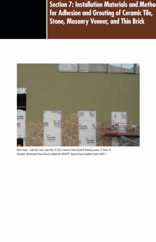
129Direct Adhered Ceramic Tile, Stone, Masonry Veneer, and Thin Brick Facades – Technical Design Manual
Section 7: Installation Materials and Methods for Adhesion and Grouting of Ceramic Tile, Stone, Masonry Veneer, and Thin Brick
129Direct Adhered Ceramic Tile, Stone, Masonry Veneer, and Thin Brick Facades – Technical Design Manual
Photo: Project – Cedar Park Center, Cedar Park, TX 2010, Contractor: Trinity Drywall & Plastering Systems, Ft. Worth, TX.Description: Manufactured Veneer Masonry installed with LATICRETE® Masonry Veneer Installation System (MVIS™).

130 Direct Adhered Ceramic Tile, Stone, Masonry Veneer, and Thin Brick Facades – Technical Design Manual
Section 7: Installation Materials and Methods for Adhesion and Grouting of Ceramic Tile, Stone, Masonry Veneer, and Thin Brick
7.1 ADHESIVE PERFORMANCE AND SELECTION CRITERIAThe performance and use of ceramic tile adhesives are regulated by country or region according to a partial listing of prominent standards shown in Figure 7.1.1. Compliance may either be mandatory or voluntary in the respective countries, depending on whether the standard is incorporated into a building code (see Section 8).
As will be discussed in Section 8, many of the standards for ceramic tile adhesive do not address specific requirements for use in cladding exterior facades. Similarly, there are minimal standards for the direct adhesion of stone or thin brick masonry, and these are contained mostly in building codes.
Criteria for Selection of Adhesivesn High adhesive strength (tensile and shear bond strength)n Water resistantn Flexible (differential movement)n Permanentn Fire and temperature resistantn Safen Good working properties (open time, pot life, sag resistance)
Standards For Ceramic Tile AdhesivesCountry or Region Standard Name / Number
Australia Standards Australia (AS) –AS 4992 – Ceramic Tiles – Grouts and Adhesives
Part 1 AS 2358 – Adhesives for Fixing Ceramic Tiles
Brazil Associação Brasileira de Normas Técnicas (ABNT) NBR 14081
China Standardization Administration of China (SAC) JC/T 547
Europe European Standards (EN) – EN 12004 – Adhesives for Tiles – Requirements, Evaluation of Conformity,
Classification and Designation
France Association Française de Normalisation (AFNOR) NF EN 12004
Germany Deutsches Insitut für Normung (DIN) EN 12004
Italy Ente Nazionale Italiano di Unificazione (UNI) EN 12004
Singapore Standards, Productivity and Innovation Board (SPRING SG) SS EN 12004
United Kingdom British Standards Institution (BSI) EN 12004
United States American National Standards Institute (ANSI) A118
Figure 7.1.1 – Worldwide standards bodies.
High Adhesive Strength (Shear and Tensile)The shearing force exerted by seismic activity is by far the most extreme force that an adhesive must be able to withstand. The shear stress exerted by an earthquake of a magnitude of 7, on the Richter Scale, is approximately 215 psi (15 kg/cm2) so this value is considered the minimum safe shear bond strength of an adhesive to both the surface of the cladding and the substrate (Figure 7.1.2).
Figure 7.1.2 – High adhesive shear and tensile strength to resist seismic movement.15 Tile remains adhered even after severe shear stress from seismic activity caused structural failure.
Water ResistanceFor proper exterior performance, an adhesive must not be soluble in water after it is cured. The adhesive should also develop water insensitivity within 24 hours so as not to require an unreasonable degree of protection against deterioration in the event of a rainstorm.
Flexible (Differential Movement)Adhesives must have a low modulus of elasticity, or flexibility, to withstand differential movement between the cladding material and the underlying substrate/structure. Differential movement can be caused by uneven or sudden temperature changes, moisture expansion or shrinkage of the cladding, substrate or the structure, or live loads such as wind or seismic activity (see Section 4).
PermanenceThe criteria of permanence may seem obvious, but even if all other performance criteria are met, beware that some “old” technology urethane or epoxy adhesives can deteriorate over time, depending on how they are chemically modified, even if installed properly. Some epoxies can become brittle

131Direct Adhered Ceramic Tile, Stone, Masonry Veneer, and Thin Brick Facades – Technical Design Manual
Section 7: Installation Materials and Methods for Adhesion and Grouting of Ceramic Tile, Stone, Masonry Veneer, and Thin Brick
with age, and some urethanes can undergo a phenomenon known as “reversion,” where the adhesive may soften and revert back to its original viscous state. Certain polymeric modification of cement mortars work only to enhance the workability and curing process, so as to improve the physical characteristics of cement, but do not contribute any significant lasting improvement to physical characteristics of the cement adhesive mortar.
Figure 7.1.3 – Magnification of conventional cement mortar (12,000x) revealing open capillaries and micro-cracks.
Fire and Temperature ResistanceWhen cured, adhesives must meet building codes and standard engineering practice by not contributing any fuel or smoke in the event of a fire. In addition, the adhesive must maintain strength and physical properties during and after exposure to the high temperatures of a fire, or from absorption of heat from solar radiation under normal service. Some types of direct adhered systems, such as those employing silicone or epoxy adhesives, may be limited in their fire resistance by the loss of adhesive strength when exposed to very high temperatures.16
SafeThe adhesive should not be hazardous during storage, installation, and disposal. This includes other materials which may be necessary for preparation or final cleaning. The adhesive should be non-toxic, non-flammable, low odor, and environmentally (VOC) compliant. LATICRETE manufactures a complete line of GreenGuard Environmental Institute low VOC certified products which are well suited for exterior façade installations. For more information on green LATICRETE® products, please visit www.laticrete.com/green.
Figure 7.1.4 – Magnification of latex modified cement mortar (12,000x) revealing latex infill of capillaries and flexible connection of micro-cracks.
Good Working PropertiesThe adhesive should have good working properties to ensure cost-effective and problem-free installation of tile, stone, masonry veneer, or thin brick. This means that the adhesive must be easy to handle, mix, and apply without having to take extraordinary precautionary measures or unusual installation steps. Good initial adhesive grab to substrate and cladding, long pot life, long open time (tacky, wet surface after spreading), vertical sag resistance (both the adhesive alone and with tile), and temperature insensitivity are all recommended working properties.

132 Direct Adhered Ceramic Tile, Stone, Masonry Veneer, and Thin Brick Facades – Technical Design Manual
Section 7: Installation Materials and Methods for Adhesion and Grouting of Ceramic Tile, Stone, Masonry Veneer, and Thin Brick
Global Tile Installation Materials StandardsInternational Organization for
Standardization (ISO)ISO 13007-1 Grouts and Adhesives – Terms, Definitions and Specifications
for Adhesives ISO 13007-2 Grouts and Adhesives –
Test Methods for AdhesivesISO 13007-3 Grouts and Adhesives – Terms, Definitions and Specifications
for Grouts ISO 13007-4 Grouts and Adhesives –
Test Methods for Grouts
European Committee for Standardization (CEN)
EN 12004 Adhesives for Tiles – Requirements, Evaluation of Conformity,
Classification and Designation EN 13813 Screed Material and Floor
Screeds -– Properties and Requirements EN 13888 Grouts for Tiles – Definitions
and Specifications EN 14891 Liquid Applied Water
Impermeable Products for Beneath Ceramic Tile Bonded with Adhesives –
Requirements, Test Methods, Evaluation of Conformity, Classification and
Designation
American National Standards Institute (ANSI)
ANSI A108 Tile Installation Standards ANSI A118 Tile Installation Materials
Specifications ANSI A136.1 Tile Installation Materials
Specification (Organic Adhesives)
Figure 7.1.5 – Worldwide Standards for Ceramic Tile Installation Materials.
7.2 TYPES OF ADHESIVESTypes of Adhesives for Direct Adhered Facades
n Cement paste or cement/sand mortar (mixed with water)
n Dispersive powder polymer-fortified cement mortar (mixed with water)
n Latex (liquid polymer) fortified cement mortar (latex in lieu of water)
n Modified emulsion epoxy adhesives (cement, water, epoxy resins)
n Epoxy resin adhesives (100% solids epoxy)n Urethane adhesivesn Silicone (structural) adhesives
Traditional Cement Mortar Mixed with WaterUntil the development and improvement of synthetic latex, polymeric and resin additives in adhesives, portland cement mixed with or without sand and gauged with water, has traditionally been used as an adhesive for exterior ceramic tile, stone, masonry veneer, and thin brick cladding. While a non-modified cement adhesive has good water resistance and is permanent, it is very brittle, and provides low adhesion only to absorptive mineral surfaces. Traditional cement mortars have poor working qualities, especially if used in thin sections. The only method where traditional cement mortar is recommended is the negative cast method of installing key-back or dovetail back external cladding to pre-cast concrete in one simultaneous procedure. The performance of this method relies primarily on the mechanical or physical locking of the concrete to the tile back.
Dispersive Powder Polymer Modified Cement MortarThis type of cement based adhesive mortar is available only as a manufactured proprietary product. There is a wide variety of this type of adhesive mortar products on the market. These materials typically are mixed with potable water; however, many dispersive powder polymer mortars can be mixed with liquid latex additive to improve performance (see latex modified cement mortar). These adhesive mortars differ mainly by the type and quantity of polymeric content. Performance characteristics may comply with either ANSI A118.1 or A118.4 standards, or, with ISO 13007 and EN 12004 requirements.
Types of Dispersive (Polymeric) Powdersn Modified cellulosen Polyvinyl acetate powder (PVA)n Ethylene vinyl acetate copolymer powder (EVA)n Polyacrylate powder
Many of the dispersive powder cement mortars available on the market are not recommended for direct adhered facades for a variety of reasons. Some of the polymers used, such as PVA’s, are water soluble and can re-emulsify after prolonged contact with moisture, causing polymer migration and resulting in staining, loss of flexibility and strength.
Most products that conform to ANSI 118.1 adhesive standards contain only water retentive additives such as cellulose, which provides only water retention for improved open time

133Direct Adhered Ceramic Tile, Stone, Masonry Veneer, and Thin Brick Facades – Technical Design Manual
Section 7: Installation Materials and Methods for Adhesion and Grouting of Ceramic Tile, Stone, Masonry Veneer, and Thin Brick
and working properties, but ultimately provides minimal improvement of strength or flexibility when compared to traditional cement mortar.
EVA modified mortars that conform to ANSI 118.4 standards may require special formulation and can vary in quantity of the polymeric powder in order to have the characteristics and physical properties required for a facade application. Many, but not all, products which employ EVA polymers have minimal resistance to prolonged moisture exposure and are not recommended for exterior facades. While dry dispersive polymer adhesives are economical and easy to use, it is recommended to verify suitability for use on exterior facades with the manufacturer, and to request or conduct independent testing to verify the manufacturer’s specified performance. However, certain polymer fortified adhesive mortars complying with ANSI A118.4 and ISO C2TES1 (e.g. LATICRETE® 254 Platinum) are suitable for the demanding conditions experienced on external facades and areas exposed to constant moisture.
Latex (Liquid Polymer) Modified Cement MortarThere are a wide variety of proprietary liquid additives that can be used with both generic cement and sand, or with proprietary cement mortar powders, including some products from the previous category of dispersive powder polymer mortars, to prepare an adhesive for external cladding materials. As with dispersive powder polymer products, the liquid additives differ mainly by the type and quantity of polymeric content.
Types of Liquid Additivesn Vinyl acetate dispersionsn Acrylic dispersionsn Styrene-butadiene latex
Liquid polymer fortified cement mortars are the most suitable adhesive for direct adhered ceramic tile, stone, masonry veneer or thin brick cladding and also are the best value when cost is compared with performance.
However, as with dispersive polymer powder mortars, not all liquid additives mixed with cement based powders are suitable for direct adhered facades. Both the type and quantity of latex polymers, as well as other proprietary chemicals, will determine if a liquid additive is suitable for facade applications.
A common and highly generalized misconception is that either acrylic polymers or styrene butadiene rubber (SBR) latex are superior to one another. This is not true. Both polymers can be formulated to have high adhesive strength, and be equally flexible. Superior performance is achieved through the formulation of these two materials.
It is recommended to verify the suitability of a latex additive for facades with the manufacturer, and conduct or request independent testing to verify the manufacturer’s specified performance. LATICRETE 211 Powder gauged with LATICRETE 4237 Latex Additive is a time proven combination which can be used over a wide variety of substrates (e.g. concrete, cmu, cement backer board, mortar beds, etc…) used for exterior façade applications.
Epoxy Resin AdhesivesEpoxy resin adhesives are typically three component systems, consisting of an epoxy resin and hardener liquids, and some type filler material, such as silica sand. Epoxy adhesives which conform to ANSI A118.3 are essentially 100% epoxy solids (e.g. LATAPOXY® 300 Adhesive, LATAPOXY 310 Stone Adhesive or LATAPOXY 310 Rapid Stone Adhesive). More economical versions of epoxy adhesives, known as modified epoxy emulsions, are also available in the market. Modified epoxy emulsions (e.g. LATAPOXY 210 Adhesive), which conform to ANSI A118.8, consist of special epoxy resins and hardeners which are emulsified in water, and then mixed with a cementitious mortar. This type of epoxy adhesive combines the economy of cement based mortars and the increased strength of epoxy adhesives.
The advantages of epoxy adhesives are that they have exceptionally high adhesive strength (shear bond and tensile strength) to most any type of substrate material, and more recent formulations have improved flexibility to accommodate differential movement.
While modified epoxy emulsions have a lower strength than 100% solid epoxy adhesives, they benefit from the higher temperature resistance and economy of portland cement adhesives.
Some disadvantages are that epoxy adhesives are significantly more expensive to purchase, and the working qualities in cold or warm temperatures, typical of most exterior facades
134 Direct Adhered Ceramic Tile, Stone, Masonry Veneer, and Thin Brick Facades – Technical Design Manual
Section 7: Installation Materials and Methods for Adhesion and Grouting of Ceramic Tile, Stone, Masonry Veneer, and Thin Brick
^United States Patent No.: 6 784 229 B2 (and other Patents).
conditions during construction, can limit production and further escalate costs. Sag resistance and temperature resistance are secondary limitations, depending on the requirements for the installation.
Full spread 100% solid epoxy adhesives (e.g. LATAPOXY® 300 Adhesive) are typically not recommended for use on facades in cold climates. The epoxy has very little permeability, and any infiltrated or exfiltrated moisture may get trapped within the wall assembly. However, a spot bond adhesive (e.g. LATAPOXY 310 Stone Adhesive or LATAPOXY 310 Rapid Stone Adhesive) can be used over concrete or double-wythe concrete walls without fear of trapping moisture within the wall. Similarly, epoxies are not recommended as a substitute for waterproofing in barrier wall type of construction (see Section 2).
Silicone (Structural) AdhesivesStructural silicone attachment of glazing materials has been in use since the early 1970’s and has been used extensively around the world to create adhesive attached glass facades. The ability of structural silicone to withstand ultraviolet radiation, while maintaining a consistent modulus of elasticity over a wide range of temperatures, and maintaining adhesion to glass and aluminum, ultimately led to use for direct adhesion of tile, stone and thin brick in the 1980’s.
Structural silicone is a special high modulus (stiff) silicone that can be used as an adhesive for direct adhered external cladding. They are typically used in proprietary cavity and pressure equalized wall construction which employ tubular aluminum or corrugated steel panels as a substrate. However, some structural silicone adhesives, known also as acid cure types, release acetic acid during the curing process, and may weaken cementitious or other mineral surfaces, including stone, The other type of silicone adhesive, known as neutral cure type, does not have the potential corrosive effect of acid cure silicones. However, neutral cure silicones are typically low modulus, extremely flexible materials with high elongation, and typically not suitable for adhesion of heavier cladding materials such as stone. Check with the manufacturer of the high modulus silicone for their recommendation and limitations as an adhesive for tile and stone installations, as well as suitability with waterproofing membranes and other construction elements.
7.3 METHODS OF INSTALLATIONThere are several methods generally used in the installation of direct adhered cladding.Adhesive Application Methods for External Cladding
n Adhesive bed (thin bed or medium bed)n Thick bed (one-step, float and butter, buttering)n Spot bond (dab, butterball method)n Negative cast (pre-cast concrete panels)
Adhesive MethodThe Adhesive Method is defined as an application of a layer of adhesive, ranging from a minimum of 1/8" (3 mm) thick, or thin bed, to a maximum of 3/4" (20 mm) thick, or medium bed, that is in full contact with no less than 95% of the bonding surface of the cladding and the substrate. The substrate is prepared to proper level and plumb tolerances in advance with the knowledge that adhesives are not intended for leveling or correcting level and plumb deviations. The adhesive can range from a pure or neat portland cement paste, to latex cement and epoxy adhesives. The thickness of the adhesive layer is dependent on the type and size of cladding, the cladding and substrate bonding surface texture, configuration of the cladding (flat or ribbed back), tolerance from consistent thickness of the tile or stone, and type of adhesive being used (e.g. LATICRETE® 254 Platinum for thin bed and LATICRETE 255 MultiMax™^ for medium bed).
A “gauged” cladding is one with consistent thickness and a specified tolerance for deviation; an ungauged cladding is not consistent in thickness and typically requires medium bed or thick bed methods of installation. Another variation of the thin bed or adhesive method is used for installing paper face mounted mosaic tile, and is known as the one step method (not to be confused with the thick bed one-step method). This technique allows both adhesive attachment and grouting in one step. The adhesive mortar is troweled on both the substrate and mosaic tile bonding surfaces. After fixing and beating the mosaic tile sheet in place and allowing an initial set, the paper face mounting paper is removed, and the adhesive mortar which was troweled into the tile joints from behind is smoothed and dressed as the joint filler. LATICRETE PermaColor™ Grout^ gauged with LATICRETE 4237 Latex Additive is an ideal combination for the one-step installation of paper-face mounted glass mosaic tile. Please refer to TDS 145 Installation of Glass Mosaic Tile which can be found at www.laticrete.com.

135Direct Adhered Ceramic Tile, Stone, Masonry Veneer, and Thin Brick Facades – Technical Design Manual
Section 7: Installation Materials and Methods for Adhesion and Grouting of Ceramic Tile, Stone, Masonry Veneer, and Thin Brick
n Spot bonding is only suitable when using adhesives with very high bonding strength and flexibility (e.g. LATAPOXY 310 Stone Adhesive and LATAPOXY 310 Rapid Stone Adhesive), and may require supplemental mechanical anchorage. The spot bonding method should not be used utilizing portland cement based adhesive mortars.
n Spot bonding should not be used in wet climates when used in conjunction with cladding materials that have high water absorption or moisture sensitivity.
n Spot bonding is not suitable for thin cladding materials that do not have the cohesive (tensile) or shear strength characteristics to resist the high unit area stress concentrations inherent in localized attachment.
n Back-up wall construction must make provision for waterproofing and flashing the cavity between the substrate and the cladding surface.
n Spot bonding may not be suitable for extreme climates or conditions.
LATAPOXY 310 Stone Adhesive (regular and rapid versions) are extremely high strength, 100% solids epoxy setting materials designed specifically for the spot bonding method. These adhesives require only 10 – 20% coverage on the back of the tile or stone (at multiple points) and can be installed onto concrete or double-wythe concrete masonry (CMU) for exterior façade installations. Poured concrete walls must be 6" (150 mm) thick, 28 days old, 3,500 psi compressive strength, and free of any form release agents, curing compounds or other potential bond breaking materials. Installation over CMU requires that the wall be double-wythe with an air gap minimum width as required by local building code. Allowance must be made at the base of the veneer wall for any entrapped water to escape to the front side of the installation. The back of stone must be clean (free of stone dust) and grinded at the points of contact with the LATAPOXY 310 Stone Adhesive (regular or rapid) to ensure maximum adhesion.*NOTE – building regulations may only allow spot bonding as a supplement to mechanical anchoring to reduce the size and complexity of mechanical anchor design, or may be restricted in height without mechanical anchors; consult local building regulations. LATAPOXY® 310 Stone Adhesive has been approved as a suitable adhesive by ICC Evaluation Service (NER-671) for exterior façade installations. For a copy of this evaluation report, please visit www.laticrete.com or www.iccsafe.org.
Generally, most dispersive powder polymer and latex cement mortars (assuming that the formulation is first evaluated for suitability as an adhesive for external cladding) are suitable for use with the thin bed or adhesive method. Follow the manufacturer’s guidelines for limitations on thickness, which varies based on formulation. Generally, thickness over 1/4" (6 mm) is not recommended for standard thin-bed or adhesive types of cement mortar mixes. Thickness over 1/4" (6 mm) typically require a medium bed mortar (e.g. LATICRETE 255 MultiMax or LATICRETE 220 Marble & Granite Mortar gauged with LATICRETE 3701 Mortar Admix), or modification of a site mix with the inclusion of additional coarse sand.
Thick Bed MethodAlso known as the “one-step,” “buttering” or “float and back-butter” method of installation, this method encompasses several different techniques. The most common thick bed technique is the “float and back butter” method. This method starts with the floating or rendering of the wall substrate with cement leveling plaster or mortar (see Section 5 – Cement Plasters/Renders). This sequence is typically a two-step process; first a “scratch” coat of mortar is applied and allowed to harden. Then a second “float” or “render” coat is applied. While the second coat remains wet and workable, a layer of adhesive is applied to the bonding surface of the cladding (referred to as “back buttering”), and the cladding is then fixed and beat into proper contact and level with adjacent cladding.
Spot Bonding Method*Also known as the “dab” method of installation, this method is where the adhesive provides only partial coverage of the cladding and substrate bonding surface (Figure 7.3.2). The thickness and area of coverage are dependent primarily on the size of the cladding unit, as well as the strength and working characteristics of the adhesive. The spot bonding method is highly specialized and restricted to certain types of substrates, cladding materials and construction situations. In some respects, this method is similar to mechanical attachment of stone to facades. The layout and accuracy of plumb and level (for the veneer) must be very precise, for once the installation begins, it becomes extremely difficult to make large adjustments. The misapplication of the spot bonding method can have serious consequences unless the architect and contractor acknowledge several important principles:

136 Direct Adhered Ceramic Tile, Stone, Masonry Veneer, and Thin Brick Facades – Technical Design Manual
Section 7: Installation Materials and Methods for Adhesion and Grouting of Ceramic Tile, Stone, Masonry Veneer, and Thin Brick
Figure 7.3.2 – Spot bonding with LATAPOXY 310 Stone Adhesive.
7.4 INSTALLATION EQUIPMENT AND PROCEDURESThe construction equipment and installation procedures required for each project and region of the world are unique, and therefore, it would not be possible to list all the types and combinations of tools, equipment and procedures involved in the installation of direct adhered cladding. This section will present the most common tools, equipment and installation procedures required for each phase of construction.
Tool and equipment requirements are determined by the phase of the installation shown below, and further defined by the type of wall construction, type of cladding material, and the type of adhesive installation.
Installation Procedures, Tools and Equipment for Direct Adhered Cladding Installation
n Substrate and cladding surfacen Preparation (see also Section 5)n Access for preparation and installation (scaffolding)n Mixing of adhesivesn Installation of adhesivesn Installation of cladding materialn Installation of joint grout/sealantsn Clean-up and protection (see Section 9)
Access for Installation (Scaffolding)The selection of scaffolding has a major impact on the productivity and resulting cost of installing a direct adhered facade. The comfort and convenience for installers, as well as the ease of transport, assembly and handling of scaffolding all contribute to the efficiency and quality control.
Physical Characteristics of LATAPOXY® 310 Stone Adhesive (Regular)
Consistency No Sag to 1" (25 mm) thickness
Pot Life at 72°F (22°C) 30 – 45 minutes
Transverse Deformation (ISO 13007-2 4.5)
3.2 – 3.6mm – S1
Shear Bond Strength (Marble to Concrete) –
ANSI A118.3 5.5 Modified
730 – 920 psi (5 – 6.3 MPa)
7 Day Cure Shear Adhesive Strength (ISO 13007-2 4.3.4)
2,610 – 4,785 psi (18 - 33 MPa)
7 Day Cure 21 Day Water Immersion Shear Adhesive
Strength (ISO 13007-2 4.3.5)
2,030 – 4,930 psi (14 - 34 MPa)
7 Day Cure – 4 100°C Water Immersion Cycles Shear Adhesive Strength (ISO 13007-2 4.3.8)
3,190 – 5,220 psi (22 – 36 MPa)
Compressive Strength (ANSI A 118.3 5.6)
8,300 – 8,450 psi (57.2 – 58.3 MPa)
Tensile Strength (ANSI A118.3 5.7)
1,500 – 2,100 psi (10.3 – 14.5 MPa)
Thermal Shock (ANSI A118.3 5.8)
1,030 – 1,600 psi (7.1 – 11 MPa)
Figure 7.3.1 – Physical Characteristics LATAPOXY® 310 Stone Adhesive.
Negative Cast (Pre-cast Concrete) MethodNegative cast panels involve the casting of the concrete and bonding of the cladding in one step. The cladding material is placed face down over the face of the panel mold; joint width and configuration are typically controlled by a grid to insure proper location, uniform jointing and secure fit during the casting operation. Joints are typically cast recessed, and pointed or grouted after the panel is cured and removed from the mold.
This method requires the use of a cladding with a dovetail or key-back configuration on the back in order to provide mechanical locking action between the cladding and the concrete. The mechanical bond strength afforded by the integral locking of the concrete to the back is often augmented by the use of latex portland cement slurry bond coats, polymeric or epoxy resin bonding agents just prior to casting of the panel.

137Direct Adhered Ceramic Tile, Stone, Masonry Veneer, and Thin Brick Facades – Technical Design Manual
Section 7: Installation Materials and Methods for Adhesion and Grouting of Ceramic Tile, Stone, Masonry Veneer, and Thin Brick
Powered Mast Climbing Work PlatformsThis system is an electrically or hydraulically powered mast climbing system which consists of a base unit, a platform, and one or two tower masts on which the platform rides (Fig. 7.4.1). Powered systems, depending on the components, can be used on buildings between 300'–500' (91–152 m) in height, but the cost of frame erection makes them most efficient on buildings less than 100' (30 m) in height. Powered systems have all the advantages of adjustable scaffolding, as well as significant safety features such as built-in guard rails, safety stops, and speed controls. The primary disadvantages are the cost and lack of availability in some regions of the world.
Multi-point Suspended (Swing Stage) ScaffoldingThis type of system is suspended from wire ropes attached to outrigger beams that are anchored to the roof or intermediate floor structure, or to temporary structural counterweights. These systems are powered either by hand winches or power driven equipment. Suspended scaffolding is typically used for high-rise construction, and becomes cost-effective at building heights of 100–125' (30–38 m). Suspended scaffolding must be engineered for each construction site, usually by the scaffolding supplier and the building contractor’s engineer. These systems have the same advantages as adjustable and mast climbing systems. In addition, there are no obstructions between the wall and the installers because suspended systems have no cross-bracing. Overhead protection is typically required by safety regulations due to work that progresses above. This can make overhead loading difficult unless the platform protection has a hatch opening.
Types of Scaffoldingn Veneer scaffoldingn Tubular frame scaffoldingn Adjustable tower scaffoldingn Powered mast climbing work platformsn Multi-point suspended scaffolding
Veneer ScaffoldingVeneer scaffolding is the simplest, most efficient, lightweight type of scaffolding. This equipment is used only for walls less than 10' (3 m) high. The system consists of a metal frame with adjustable, stabilizing legs that do not require cross-bracing, and wood or metal platform planks. Vertical adjustment can be made in small 3" (75 mm) increments.
Tubular Frame ScaffoldingTubular frame scaffolding is the most common type of scaffolding, consisting of a tubular metal frame and cross-braces which give the system stability. This system is most efficient in buildings under 30' (10 m) in height, because it is a stacked system. Some advantages are that the components of the system are very common, it adapts easily to recesses and projections in an exterior wall, and it is the easiest type of system to enclose for hot or cold weather protection. Disadvantages are that this type of system can only be adjusted in large increments at each level of the frame, and that each successive level must be built before it can be stocked and occupied.
Adjustable Tower ScaffoldingMost adjustable scaffolding consists of a base, towers, cross-braces, carriage, winch (hoisting) assembly, guardrails and plank platform. These systems are most efficient on buildings up to 75' (23 m) in height, but can be used up to 100' (30 m). The hand operated winch raises the platform along the carriage towers. This system can be easily adjusted in any vertical increments, and the entire assembly can be lifted and transported by forklift to adjacent walls. Many proprietary designs provide separate loading/stocking and working platforms. Studies have shown that adjustable scaffolds can increase labor productivity by 20% over conventional frame scaffolding.

138 Direct Adhered Ceramic Tile, Stone, Masonry Veneer, and Thin Brick Facades – Technical Design Manual
Section 7: Installation Materials and Methods for Adhesion and Grouting of Ceramic Tile, Stone, Masonry Veneer, and Thin Brick
[27 – 38°C]) and surface (150 – 170°F [66 – 77°C]) temperatures will accelerate setting of cement, latex cement, epoxy and silicone adhesives. Washing and dampening walls will not only remove some surface contaminants, but also serve to lower surface temperatures by evaporative cooling for cement latex mortars and moisture insensitive epoxy adhesives. Shading surfaces is typically effective in lowering surface temperature, but if ambient temperatures still exceed 95°F (35°C), it is advisable to defer work to another time when temperatures are cooler (e.g. night, early morning, etc…). If work cannot be deferred, it is also possible to cool additives prior to mixing, in conjunction with the above techniques. Please refer to LATICRETE TDS 176 “Hot Weather Tiling and Grouting”, available at www.laticrete.com, for more information.
Conventional portland cement tile-setting beds, thin-set mortars, cement plasters and stuccos can be permanently damaged when subjected to hot, dry temperature or desert climates immediately after installation. High temperatures can quickly cause the water content of the mortar required for cement hydration, curing and strength development to evaporate. In addition, rapid drying can cause a mortar to crack, crumble or lose bond. Waterproofing membranes, anti-fracture membranes, epoxy adhesives, epoxy grouts, epoxy membranes, and most other products will also be affected by hot working temperatures. Flash setting and reduced working time can result. It is important to note that surface temperature is more important than air temperature; so monitoring of the surface temperature is important.
The use of premium latex-fortified mortars (e.g. LATICRETE® 254 Platinum, or, LATICRETE 211 Powder gauged with LATICRETE 4237 Latex Additive) allows installations to be made at higher temperatures due to the fact that they have longer working properties. LATICRETE 3701 Mortar Admix in thin-sets and other portland cement mortars allow work to continue without costly delays or damage in some hot conditions. Installations can be made on surfaces with temperatures as high as 90°F (32°C) under normal circumstances. LATICRETE latex fortified mortars are not damaged by high temperatures (up to 95°F [32°C]) and thermal shock after placement, and often eliminates the need for damp curing.
Figure 7.4.1 – Powered mast climbing scaffolding.17
Figure 7.4.2 – Multi-point suspended scaffolding system.18
Weather ProtectionThe optimum conditions for installation of direct adhered cladding are temperatures between 60° and 80°F (16° and 27°C), with 50% relative humidity and minimal wind. However, these conditions are atypical, so provisions must be made for variations in climatic conditions. Protection applies to the substrate (see Section 5), the installation of adhesives and joint grouts, post-installation (rain and temperature protection) until suitable cure, and also the storage and handling of the cladding material. The standard rule of thumb (as stated in Chapter 5) applies: For every 18°F (10°C) above 70°F (21°C) cementitious and epoxy materials cure twice as fast. For every 18°F (10°C) below 70°F (21°C) cementitious and epoxy materials take twice as long to cure.
Hot Temperatures – Protection or corrective action is required if either ambient air or surface temperatures of substrates/cladding go above certain thresholds during installation. Temperature thresholds vary with the types of adhesives, but generally, elevated ambient air (80 – 100°F

139Direct Adhered Ceramic Tile, Stone, Masonry Veneer, and Thin Brick Facades – Technical Design Manual
Section 7: Installation Materials and Methods for Adhesion and Grouting of Ceramic Tile, Stone, Masonry Veneer, and Thin Brick
n Tent off areas of work to provide shade when working in direct sunlight.
n Work during cooler periods of the day (e.g. early morning).
Cold Temperatures – Protection or corrective action is often required if either ambient air or surface temperatures of the substrate go below certain thresholds during installation. Temperature thresholds are different for various types of adhesives. Protection and corrective actions to elevate temperatures to optimum range typically involve enclosing or tenting of work areas, augmented by temporary heating (see Figure 7.4.3). Some types of scaffolding have proprietary equipment accessories for temporary temperature protection. If temporary heating is employed, it is very important to vent units to the exterior of enclosures to prevent exposure to toxic fumes, and also to prevent build-up of carbon dioxide, which can cause carbonation of cementitious materials.
Carbonation will typically occur when ambient temperatures during installation are around 40°F (5°C) and usually only affects exposed surfaces. The length of exposure is a function of temperature. Cement hydration stops at 32°F (0°C) surface temperature, when water necessary for hydration freezes, and hydration is retarded starting at 40°F (5°C). Concentration of carbon dioxide can be elevated when temporary heating units are not properly vented outside of any protective enclosure during cold temperatures. As a general rule, temperatures should be maintained above 50°F (10°C) during installation of cement, epoxy and silicone based products. Some cement adhesive product formulations may allow installation in temperatures close to 32°F (0°C) and rising, however, at this critical ambient air temperature threshold, it is likely that surface temperatures are below freezing due to thermal lag, and hydration or other chemical reaction may not occur at the adhesive interface. Please refer to LATICRETE TDS 175 “Cold Weather Tiling and Grouting”, available at www.laticrete.com, for more information.
General tips for working in hot temperatures:n For best results, always ship and store installation materials
at 40º – 90°F (5º – 32°C) to extend the shelf life and working time. Do not store products in direct sunlight. If installation materials are too warm, they should be cooled to the specified temperature range for that specific product.
n Dampen or wet down substrate surfaces to not only clean the area, but to lower the temperature and lower the absorption rate of the substrate. Sweep off excess water just before mortar is applied. This step will extend the working time of the installation materials.
n Stir latex additives thoroughly before mixing with thin-sets, grouts, plasters, stuccos and other portland cement mortars.
n Due to the rapid rate of moisture loss and portland cement dehydration at temperatures >90°F (>32°C), cover installations with polyethylene sheeting for 1–2 days to allow curing at a more normal rate.
n Low humidity also accelerates the curing process. n Tent off or provide shade when working in direct sunlight.n Work during cooler periods of the day (e.g. early
morning).
Tips for grouting in hot temperatures:n Store grouting materials at 40º – 90°F (5º – 32°C) to
extend the shelf life, pot life and working time. Do not store products in direct sunlight. If installation materials are too warm, they should be cooled to the specified temperature range for that specific product 24 hours prior to the start of grouting.
n Dampen or wet down substrate surfaces to not only clean the area, but to lower the temperature and lower the absorption rate of the substrate.
n Always clean the mixing pail before mixing a fresh batch of grout. Left over grout in the pail (on bottom and sides) can accelerate the setting of freshly mixed grout.
n Mix cement grouts with clean cool water. This step will extend the pot life and open time of cement grouts.
n Remix cement grouts after approximately15 – 20 minutes (after initial mixing, 5 minutes of slaking/remix and use) to an even consistency and to prolong pot life.

140 Direct Adhered Ceramic Tile, Stone, Masonry Veneer, and Thin Brick Facades – Technical Design Manual
Section 7: Installation Materials and Methods for Adhesion and Grouting of Ceramic Tile, Stone, Masonry Veneer, and Thin Brick
For best results, always ship and store installation materials at temperatures above freezing so they will be ready to use when needed.
n If LATICRETE liquid latex admixtures and liquid membranes are ever frozen, allow them to thaw completely before use. Allow the products to come up to room temperature of approximately 70ºF (21ºC). Stir contents thoroughly before use or before mixing with thin-sets, grouts and other portland cement mortars.
n LATICRETE and LATAPOXY® liquid pouches stored in cooler temperatures should be warmed by submerging the unopened pouches in warm water (not hot) until the material is sufficiently tempered.
n Acclimate waterproofing membranes, crack isolation and sound control products to their respective usage temperature range prior to use.
n Store all thin set mortars and grouting products in a warm area for 24 hours prior to use.
ProtectionDue to the slow rate of portland cement hydration and strength development at low temperatures, protect installations from traffic for longer than normal periods. Keep all traffic off of finished work until full cure. For example, installations which will be subjected to vehicular traffic should cure for 7 days at 70ºF (21ºC) prior to vehicle traffic. Allow extended cure time, based on the 18º Rule (above), for installation in cooler temperatures. It is important to note that large format tiles and stone will also require longer curing periods in cooler temperatures. Suitable protection should be included in the scope of work. For example, the Tile Council of North America (TCNA) Handbook for Ceramic, Glass, and Stone Tile Installation under the heading “Protecting New Tile Work” states: “Builder shall provide up to 3/4" (19 mm) thick plywood or OSB protection over non-staining Kraft paper to protect floors after installation materials have cured”.
In addition, extended cure periods will be required for applications that include multiple layer build ups (e.g. mortar beds, waterproofing, sound control, crack isolation, epoxy grout, etc…). Each component must reach a proper cure prior to installing the subsequent installation product.
Figure 7.4.3a and 7.4.3b – LATICRETE Corporate Headquarters Building, Bethany, CT USA during façade cladding in January 2008.
Conventional portland cement tile setting beds, thin-set mortars, grouts and cement plasters are often permanently damaged when subject to below freezing temperatures immediately after installation. The water content of a mortar turning into ice often results in portland cement gel structure rupturing with significant loss in strength, flexibility and durability. Subsequent repairs to the damaged work and resulting site delays are extremely costly.
The use of LATICRETE® 4237 Latex Additive in thin-sets and LATICRETE 3701 Mortar Admix in thin-sets, grouts, plasters, stuccos and other portland cement mortars allows work to continue in cold weather without costly delays or damage. Frost, ice and thermal shock do not damage LATICRETE latex fortified mortars after placement. Installations can be made at temperatures as low as 35°F (2°C).
The use of a premium rapid-setting thin-set mortar (e.g. LATICRETE 254R Platinum Rapid) will also help to accelerate the setting time in cooler temperatures. In addition, the use of a rapid setting latex additive (e.g. LATICRETE 101 Rapid Latex Admix) mixed with an unmodified thin-set mortar (e.g. LATICRETE 317), medium bed mortar (e.g. LATICRETE 220 Marble & Granite Mortar) and other suitable cement based products allows work to take place and can quickly return newly tiled areas back to service in cooler temperatures.

141Direct Adhered Ceramic Tile, Stone, Masonry Veneer, and Thin Brick Facades – Technical Design Manual
Section 7: Installation Materials and Methods for Adhesion and Grouting of Ceramic Tile, Stone, Masonry Veneer, and Thin Brick
A damp substrate may also contribute to the formation of efflorescence (see Section 9 – Efflorescence). This is of particular concern not only from normal rain exposure during construction, but, also in areas of a facade which may be exposed to rising dampness at ground level, and in areas where leaks from poor design or construction cause continual dampness in the substrate.
When specifying liquid latex or dry dispersive polymer adhesive mortar, verify with the manufacturer that the polymer formulation is not water soluble. However, it is important to note that even formulations which are not soluble when dry are vulnerable to rain or water exposure during the initial set period (typically 24 – 48 hours). Therefore, it is essential to provide protection from any significant rain or washing within this period to avoid loss of strength and prevent fluid or latex migration staining (see Section 9 – Fluid Migration).
Protection and corrective action primarily requires temporary enclosures or tarpaulins prior to, during, and immediately after installation to shield from rain. If prolonged exposure occurs, surfaces that appear dry may be saturated internally and require testing to determine suitability of certain overlay substrates, membranes or adhesives (see Section 9 – Moisture Content Testing).
Substrate and Cladding Surface PreparationProper cleaning of the cladding and substrate surface prevents contamination from inhibiting adhesive bond. Preparation and cleaning of substrates are covered in Section 5. While careful consideration is often given to the preparation of the substrate, preparation and cleaning of the cladding bonding surface is an often overlooked specification item or quality control checkpoint. Considerations are dependent on the type of cladding material.
Ceramic Tile – The bonding surface of ceramic tile is often contaminated with dirt or dust from normal manufacturing, storage and handling. Porcelain tile may have a coating of a release agent (known by terms such as bauxite or engobe) which prevents fusion of the tile to kiln surfaces during the firing process. The type and amount of this release agent prior to shipping will vary according to manufacturer or production batch. Tile manufactured especially for external cladding applications with a dovetail back configuration are less susceptible to surface contamination due to the safety factor provided by both mechanical and adhesive bond.
Helpful Hintsn Work during warm periods of the day.n Ensure that the surface temperature is within the suggested
temperature range for the LATICRETE or LATAPOXY® product being used during the installation and cure period. Consult the individual LATICRETE or LATAPOXY product data sheet and How-to-Install guide for more information.
n Tent and heat areas that will be subjected to the elements or freezing temperatures during installation and cure periods.
n For multiple story buildings – areas to receive tile and stonework may be heated from below to aid in “warming up” cold concrete slabs and rooms. Simply placing temporary heating units in areas under rooms scheduled to receive tile and stone finishes in multiple story buildings will allow the natural rise of heat to warm up these areas.
n Vent all temporary heating equipment in accord with OSHA (Occupational Safety and Health Administration) and local building code regulations.
Dry, Windy Conditions – Dry and/or windy conditions can cause premature evaporation of water necessary for hydration in cementitious materials, which can result in loss of strength. Latex additives are formulated to significantly reduce this drying effect by coating water with a latex film. However, in extreme dry, windy conditions coupled with high temperatures (>90°F [>32°C]), even latex additives do not provide adequate protection.
It is recommended to provide temporary protection against rapid evaporation of moisture during hot, dry, and/or windy conditions in the initial 36 hours after installation of cement plasters/renders and cement grouts. It would also be beneficial to damp cure with periodic water misting. Cement based adhesives are only susceptible to premature drying between the spreading of adhesive and the installation of the cladding, and requires only temporary protection from hot, dry, and/or windy conditions during the open or exposed time of the adhesive.
Wet Conditions – Certain materials used in direct adhered exterior wall assemblies are moisture sensitive. For example, the strength of cementitious adhesives can be reduced from constant exposure to wet or damp substrates. Some materials, such as waterproofing membranes, may not cure properly or can delaminate from a continually wet or damp substrate.
142 Direct Adhered Ceramic Tile, Stone, Masonry Veneer, and Thin Brick Facades – Technical Design Manual
Section 7: Installation Materials and Methods for Adhesion and Grouting of Ceramic Tile, Stone, Masonry Veneer, and Thin Brick
saturating the surface is more important to prevent absorption of soluble salt residue (potassium chloride) which cannot be surface neutralized and rinsed with water. This can lead to an efflorescence problem, or may deposit salts that can inhibit adhesive bond intended to be corrected by the acid cleaning.
Application of acid solutions should be left to dwell for no more than 5 minutes before brushing with a stiff acid resistant brush and immediately rinsing with water. Acid solutions can also be neutralized with a 10% solution of ammonia or potassium hydroxide to prevent residue contamination. Care must also be taken to prevent contact with the polished surface of a stone to avoid etching of the finish. Any exposed metal in the area of acid use should be protected from physical or acid fume exposure.
Masonry Veneer – Masonry veneer cladding materials are formed using natural aggregates and a binder. Unless the veneer unit is mesh or resin backed, no special precautions should be necessary other than to remove dirt, dust or other contamination which may have occurred during the storage or shipping of the product. Check with the veneer manufacturer for any special requirements for preparation.
Thin Brick – This type of cladding typically has a rougher, more open pore structure and should have a dovetail configuration manufactured specifically for external direct adhered cladding applications. As a result, thin brick is less susceptible to contamination due to the safety factor provided by both mechanical and adhesive bond. There are no specific cautions other than to remove normal dirt caused by storage and handling with low pressure water or sponge washing prior to installation. Check with the thin brick manufacturer for any special requirements for preparation.
Adhesive Mixing Equipment and ProceduresEquipment and tools required for mixing of adhesives are primarily dependent on the type of adhesive being mixed and construction site conditions (e.g. climate, size of project, et al).
Latex Cement and Dispersive Powder Polymer Fortified Cement Adhesive MortarsManual Mixing
n Bucket, trowel and mixing paddle
It is recommended to wipe each tile with a clean, damp towel or sponge during or just prior to installation to maximize adhesive bond. If a water sensitive adhesive such as silicone is used, the surface must be allowed to dry. Dry dispersive polymer cement and latex cement adhesive mortars can be applied to a damp, but not wet (saturated) surface (see Section 9 – Moisture Content Testing).
Stone and Agglomerates – In addition to cleaning the bonding surface from normal storage and handling dust as described above, some stone may require more extensive cleaning depending on the fabrication process. During the sawing and grinding processes, fine stone slurry may leave a coating of dust, or get ground into the bonding surface and form a weak, hardened layer of contamination. In most cases, washing with water, preferably at moderate pressure of 1,500 psi (10.3 MPa), together with light scrubbing with a bristle brush, is adequate to remove stone dust or hardened slurry. However, in some cases hardened slurry may require a light acid etching to remove the hardened material. The need for more aggressive cleaning can only be determined by laboratory shear and tensile bond tests to determine the effectiveness of simple water cleaning. Conducting diagnostic tests during the design and specification process (see Section 9.1 – Quality Assurance) can avoid costly problems and delays during the construction phase or during service life.
The need for acid washing indicates that stone has not been fabricated to specification or for the intended application, so be sure to include this consideration in the specifications or during the selection of the stone and fabricator. Acid washing should only be a last resort if testing indicates contamination by hardened slurry. Acid washing involves washing the bonding surface with a dilute solution (5–10%) of hydrochloric (muriatic) acid. Aqueous (pre-diluted) solutions of acid are commercially available for ease of handling and prevention of dilution errors.
Before applying any acid solution, always test a small, inconspicuous area to determine any adverse effect. Different stones have different levels of acid resistance, so dilution may need adjustment as a result of conducting a test sample. Just prior to application, saturate the surfaces with water to prevent acid residue from absorbing below the surface. While most acids quickly lose strength upon contact with the minerals in stone and do not dissolve minerals below the surface,

143Direct Adhered Ceramic Tile, Stone, Masonry Veneer, and Thin Brick Facades – Technical Design Manual
Section 7: Installation Materials and Methods for Adhesion and Grouting of Ceramic Tile, Stone, Masonry Veneer, and Thin Brick
Epoxy AdhesivesManual Mixing
n Bucket and trowel
Mechanical Mixingn Low speed drill (<300 rpm) and non-air entraining mixer blade
The mixing instructions for epoxy adhesives vary according to manufacturer’s formulations. The most common epoxy adhesives are composed of three components (e.g. LATAPOXY® 300 Adhesive), which involve mixing of two liquids (resin and hardener), and a powder (silica filler). The liquids are mixed together first and fully blended before adding filler powder. There are several important considerations in mixing epoxies. First, the chemical reaction begins immediately upon mixing the epoxy resin and hardener. Because the “pot life” or useful life of the adhesive is relatively short (1 hour) and can be further reduced by ambient temperatures above 70°F (21°C), all preparation for mixing and installation of the epoxy adhesive should be made in advance. Mixing should also be made in quantities that can be installed within the prescribed useful life under installation conditions.
High strength, two component epoxies (e.g. LATAPOXY 310 Stone Adhesive and LATAPOXY 310 Rapid Stone Adhesive) are now available which can be used for exterior façade installation of tile, stone, masonry veneer, or thin brick. Check with the product manufacturer for product suitability and specific installation guidelines for the intended use.
LATAPOXY 310 Stone Adhesive and LATAPOXY 310 Rapid Stone Adhesive can be installed using the LATAPOXY 310 Cordless Mixer for fast and easy installation of tile, stone and masonry veneer (See Figure 7.4.6).
Figure 7.4.6 – Dabs of LATAPOXY® 310 Rapid Stone Adhesive in cartridge packs being applied using the LATAPOXY 310 Cordless Mixer.
Mechanical Mixingn Low speed drill (< 300 rpm) and non-air entraining mixer
blade (Fig. 7.4.5)n Rotating blade (forced action) batch mortar mixer (Fig. 7.4.5)
NOTE: Rotating drum type concrete mixers are not suitable for mixing adhesive mortars.
In mixing cement adhesive mortars, always add the gauging liquid (water or latex additive) to the mixing container or batch mixer first. Begin mixing and add the dry cement based powder gradually until all powder is wet, then continue mixing for approximately one minute or until mortar is wet and plastic. If using site prepared powder mixes of portland cement and sand, add the sand first until it is wet, then add the cement powder.
Take caution to prevent over-mixing by blending only until the mortar is wet and plastic or in accordance with the manufacturer’s instructions. Over-mixing can entrap air in the wet mortar and can result in reduced density and lower strength.
Figure 7.4.4 – Mortar mixing equipment.
Figure 7.4.5 – Rotating blade type mortar mixer.

144 Direct Adhered Ceramic Tile, Stone, Masonry Veneer, and Thin Brick Facades – Technical Design Manual
Section 7: Installation Materials and Methods for Adhesion and Grouting of Ceramic Tile, Stone, Masonry Veneer, and Thin Brick
available and cost-effective, it is foolish to expect maximum specification strength over the entire adhesive interface hidden from visual inspection.
Figure 7.4.7 – Mechanical adhesive mortar mixing equipment.
Installation of Ceramic tile, Stone, Masonry Veneer, and Thin Brick CladdingThe following are the basic tools and equipment used for the installation of the external cladding:
Equipment for Application and Bedding of Adhesives and Joint Grouts
n Notched steel troweln Flat steel troweln Margin troweln Hawkn Metal applicator gun (silicone spot bonding only)n LATAPOXY® 310 Cordless Mixer (LATAPOXY 310 Stone
Adhesive [regular and rapid] only)n Rubber malletn Wood beating blockn Vibratorn Spacer shims and wedgesn Heavy duty suction cup lifter w/releasesn Grout float (cement or epoxy)
Cutting/Fitting of Cladding Materialsn Masonry sawn Wet saw (tile)n Ceramic tile cutter and accessories
Measurementn Carpenter’s leveln Laser leveln 4' minimum straight edge (1200 mm)
Epoxy adhesives cure by an exothermic or heat generating chemical reaction beginning with the mixing of the liquid components. The useful life of the epoxy not only begins before adding the filler powder, but the heat generated may accelerate the curing process in many formulations. Removal of the mixed epoxy from the mixing container is one technique used to dissipate heat generation and minimize set acceleration, thereby extending pot life and open time based on environmental conditions. Liquid components may also be cooled or warmed (to approximately 70°F [21°C]) if anticipated ambient or surface temperatures will significantly are outside of the recommended use temperature range. Conversely, epoxy adhesive cure is retarded by cold temperatures, and the curing process may stop at temperatures below 40°F (5°C); the curing process will typically continue unaffected if temperatures are raised.
Silicone and Urethane AdhesivesThese adhesives are typically pre-mixed and ready to use. Exceptions may be reactive two-component urethanes, or bulk packaging which may need loading into applicator guns. Most silicones are available in pre-mixed cartridges, or in plastic wrapped “sausages” which are loaded into either manual or hydraulically operated metal applicator guns.
Cladding Installation Equipment and ProceduresThere is a significant difference in the size of porcelain mosaic tile or thin bricks compared to large format porcelain tile or large pieces of stone. Each size and type requires different installation techniques and/or tools. However, the basic concept of installation of external cladding using the direct adhered method is the same. The entire surface of the cladding material is adhered (with the exception of epoxy or silicone spot bonding), and the basis for evaluating adhesion performance is by strength of a unit area; the size of the cladding material is affected only by the logistics of construction and any legal/building code requirements.
High quality adhesives are designed to bond at safety margins of about 250–400% of the required strengths. The reason for the high safety factor is, of course, to compensate for the unforeseen extreme forces (e.g. earthquake), and the difficulty in determining quality control of labor. Until sophisticated diagnostic quality control test methods become more readily

145Direct Adhered Ceramic Tile, Stone, Masonry Veneer, and Thin Brick Facades – Technical Design Manual
Section 7: Installation Materials and Methods for Adhesion and Grouting of Ceramic Tile, Stone, Masonry Veneer, and Thin Brick
The notched steel trowel also aids in efficient application of adhesive mortars. Logic dictates that openings in the edge of the notched trowel create less physical resistance and more control than a closed flat edge.
Figure 7.4.8 – Notched trowel sizes for installation of external cladding adhesive mortars.
It is important to maintain the specified notch depth and configuration of the trowels. The angle of application can have a significant effect on the height of adhesive ribs, which in turn can affect the height to width ratio of the adhesive ribbons necessary for control of thickness and elimination of air voids. Therefore, it is recommended to prohibit the common use of severely worn trowels and to require frequent cleaning and specification of application angle as part of the specification and quality control inspection program.
Flat steel trowels are used to apply an initial thin layer of adhesive into positive contact with both the bonding surface of the cladding (also known as back-buttering) and the surface of the substrate. The opposite side of a notched trowel typically has a flat edge for this purpose.
Rubber mallet, wood beating block and vibrator are all tools which are used to impart even setting pressure to the cladding material to assure full contact with the adhesive, and minimize any voids in the adhesive layer (Fig. 7.4.10). These tools also apply even pressure in order to adjust the surface plane of the cladding materials to level and plumb tolerances.
The use of vibrators has improved the quality of the critical adhesive interface of external cladding in countries such as Japan. Small hand-held vibrators, or adaptations of vibrating sanders that vibrate at a frequency of 200 Hz and amplitude of 0.4 mm held for one second at each of the corners and interior areas of the cladding have proven successful in achieving consistent coverage and contact of adhesives.
Clean-upn Sponges, towelsn Water bucketn Solvents (for epoxy or silicones – if required by adhesive
manufacturer)
Safety Equipmentn Safety glassesn Rubber glovesn Dust mask/respiratorn Safety belts and harness
The notched steel trowel is the primary and most fundamentally critical installation tool for the thin bed or medium bed method of installation (See Figure 7.4.8). A notched trowel has several important functions that contribute to a successful installation of external cladding:
Functions of a Notched Troweln Gauges the proper thickness of adhesiven Provides proper configuration of adhesiven Aids in efficient application of adhesive
The proper thickness of the adhesive layer is dependent on the type and size of cladding, the cladding and substrate bonding surface texture, configuration of the cladding, and tolerance of the cladding from consistent thickness. A “gauged” or “calibrated” cladding is one with a consistent thickness and a specified tolerance for deviation; an “ungauged” cladding is not consistent in thickness. Even gauged stone has thickness tolerances of up to 1/8" (3 mm). Notched steel trowels are available in several sizes and configurations to help control the thickness of applied adhesive mortar.
The configuration of adhesive application is critical to performance of external cladding. In addition to controlling final thickness of adhesive, the notched configuration results in “ribbons” or “ribs” of adhesive separated by spaces that control bedding or setting of the cladding into the adhesive. The spaces allow the ribs of adhesive to fold into one another to decrease the resistance to pressure required for proper contact, and provide a controlled method of filling all air voids and allowing escape of air parallel to the ribs. This function is critical in assuring full contact and coverage of adhesive, not only to ensure maximum bond strength, but also to eliminate air voids or channels which can harbor or transport water.

146 Direct Adhered Ceramic Tile, Stone, Masonry Veneer, and Thin Brick Facades – Technical Design Manual
Section 7: Installation Materials and Methods for Adhesion and Grouting of Ceramic Tile, Stone, Masonry Veneer, and Thin Brick
6. The final step is to beat-in with a rubber mallet, a wood beating block, or a mechanical vibrator to ensure maximum adhesive contact and make the cladding surface level with the adjacent cladding surface.
Installation Procedure for Cladding Using Thick Bed Mortar (Wet Set)
1. Prepare thick bed mortar (e.g. LATICRETE® 3701 Fortified Mortar Bed) in accordance with installation instructions and guidelines for mixing provided on packaging for vertical installations. For site mixes, a 3:1 sand/cement mix gauged with a suitable latex additive is recommended.
2. First, apply a scratch coat of mortar (e.g. LATICRETE 254 Platinum or LATICRETE 3701 Fortified Mortar Bed) with a flat trowel in good contact with the wall/substrate surface. Allow the scratch coat to dry.
3. Next apply a leveling coat of thick bed mortar to the desired thickness or 1/2" (12 mm). If another lift of thick bed mortar is required, scratch previous layer and allow to dry. As soon as the final thickness of mortar is achieved, smooth surface to plumb and level.
4. Next apply an adhesive bond coat (e.g. LATICRETE 254 Platinum) to the back surface of the cladding, apply to the wet mortar and beat into place using a beating block and rubber mallet.
5. Once the cladding is beat-in and bedded in place to proper level and plumb. If required, the cladding must be supported over lower courses by spacers to prevent slippage and to maintain joints.
6. Use a wet sponge to clean any excess mortar from the face of the cladding before it hardens.
7. Depending on adhesive manufacturer’s instructions, you may remove temporary supports at the first course and spacers in the joints after 24 hours. However, temperatures at or below 40°F (5°C) may require longer cure before removal of supports with larger, heavier cladding materials).
Spacers or shims provide temporary gravity support of each successive course of cladding until the adhesive reaches sufficient strength to support the weight of the cladding. Spacers should be a manufactured product or a material of consistent thickness in order to accurately maintain horizontal and vertical joints between the cladding units.Installation Procedure for Cladding using Thin Bed Adhesives
1. Apply a 1/16" (1.5 mm) thick skim coat of adhesive to the properly prepared dampened substrate with the flat side of the trowel; ensure good contact by scratching the edge of the trowel against the surface.
2. Additional adhesive is then applied with the notched side of the trowel. Comb the mortar horizontally onto the wall with the notched trowel, holding it as close as possible to a 90° angle to the wall. This will help ensure the proper size of notches.
3. The ribs of adhesive should be troweled in a single, horizontal direction only, and not in a swirl pattern. If additional thickness of adhesive is needed, add to the back of the cladding using the same procedure as on the wall, making sure that the direction of the combed mortar is identical to the one on the wall, otherwise, you can end up with notches in two directions that disturb each other and consequently will not allow full contact between the mortar and the back of the cladding.
4. As a rule, cladding sizes bigger than 8" x 8" (200 x 200 mm) and cladding of any size with a dovetail or lugged back, and stone of any size should be back buttered when applied to facades. Back buttering not only improves the contact between the mortar and the back of the cladding, but ensures complete coverage. However, back-buttering does not mean that 100% coverage is necessarily attained, since voids can still exist in the combed adhesive between the back-butter layers. Proper installation methods and random checking of adhesive coverage will help ensure that maximum coverage is achieved.
5. Small unit cladding should be pressed into place, and either twisted and pressed into position, or, for cladding sizes 12" x 12" (300 x 300 mm) and greater, slide into position with a back and forth motion perpendicular to the direction of the adhesive ribs.
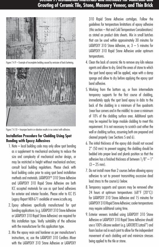
147Direct Adhered Ceramic Tile, Stone, Masonry Veneer, and Thin Brick Facades – Technical Design Manual
Section 7: Installation Materials and Methods for Adhesion and Grouting of Ceramic Tile, Stone, Masonry Veneer, and Thin Brick
310 Rapid Stone Adhesive cartridges. Follow the guidelines for temperature limitations of epoxy adhesive (this section – Hot and Cold Temperature Considerations) as stated on product data sheets. Mix in small batches that can be used within approximately 30 minutes for LATAPOXY 310 Stone Adhesive, or, 3 – 5 minutes for LATAPOXY 310 Rapid Stone Adhesive under optimum temperatures.
4. Clean the back of ceramic tile to remove any kiln release agents and allow to dry. Grind the areas of stone to which the spot bond epoxy will be applied, wipe with a damp sponge and allow to dry before applying the epoxy spot bond adhesive.
5. Working from the bottom up, or from intermediate temporary supports for the first course of cladding, immediately apply the spot bond epoxy in dabs to the back of the cladding in a minimum of five quadrants (near four corners and in the middle) to cover a minimum of 10% of the cladding surface area. Additional spots may be required for large module cladding to meet this requirement. It is not necessary to scratch coat either the wall or cladding surface, assuming both are prepared and cleaned properly (see Sections 5 and 6).
6. The initial thickness of the epoxy dab should not exceed 2" (50 mm) to prevent sagging; the cladding should be bedded into proper level and plumb position so that the adhesive has a finished thickness of between 1/8" – 1" (3 – 25 mm).
7. Do not install more than 2 courses before allowing epoxy adhesive to set to prevent transmitting excessive dead load stress to the course(s) below.
8. Temporary supports and spacers may be removed after 24 hours at optimum temperatures (68°F [20°C]) for LATAPOXY 310 Stone Adhesive and 15 minutes for LATAPOXY 310 Rapid Stone Adhesive; cooler temperatures may require additional curing time.
9. Exterior veneers installed using LATAPOXY 310 Stone Adhesive or LATAPOXY 310 Rapid Stone Adhesive should use a 100% silicone sealant (e.g. LATICRETE Latasil™) and foam backer rod in each joint to allow for the independent movement of each cladding unit and minimize stresses being applied to the tile or stone.
Figure 7.4.9 – Example of incomplete bedding caused by omission of back buttering.
Figure 7.4.10 – Improper beat-in or vibration results in no contact with adhesive.
Installation Procedure for Cladding Using Spot Bonding with Epoxy Adhesives
1. Note – local building code may only allow spot bonding as a supplement to mechanical anchoring to reduce the size and complexity of mechanical anchor design, or may be restricted in height without mechanical anchors; consult local building regulations. Please check with local building codes prior to using spot bond installation methods and materials. LATAPOXY® 310 Stone Adhesive and LATAPOXY 310 Rapid Stone Adhesive are both ICC accepted materials for use as spot bond adhesives for exterior and interior facades. Please refer to ICC ES Legacy Report NER-671 available at www.iccsafe.org.
2. Epoxy adhesives specifically manufactured for spot bonding applications (e.g. LATAPOXY 310 Stone Adhesive or LATAPOXY 310 Rapid Stone Adhesive) are required for this installation type. Verify suitability of the adhesive with the manufacturer for this application type.
3. Mix the epoxy resin and hardener as per manufacturer’s instructions, or, use the LATAPOXY 310 Cordless Mixer with the LATAPOXY 310 Stone Adhesive or LATAPOXY

148 Direct Adhered Ceramic Tile, Stone, Masonry Veneer, and Thin Brick Facades – Technical Design Manual
Section 7: Installation Materials and Methods for Adhesion and Grouting of Ceramic Tile, Stone, Masonry Veneer, and Thin Brick
Please note that many “stacked” type adhered masonry veneer products are installed with open (empty) mortar joints. Consult with the adhered manufactured masonry veneer manufacturer for their recommendations and guidelines in treating these joints.
Compensate for Cladding TolerancesThe joints between cladding help to compensate for allowable manufacturing or fabrication tolerances of the cladding, so that consistent dimensions (from center to center of joints or full panel dimensions) can be maintained. As a result, joints must be wide enough to allow variations in the joint width to accommodate manufacturing or fabrication tolerances in the cladding without being evident. According to ANSI A108.02 4.3.8 the following statement is used to explain typical grout joint size width requirements; “To accommodate the range in facial dimensions of the tile supplied for a specific project, the actual grout joint size may, of necessity, vary from the grout joint size specified. The actual grout joint size shall be at least three times the actual variation of facial dimensions of the tile supplied. Example: for tile having a total variation of 1/16" (1.5 mm) in facial dimensions, a minimum of 3/16" (5 mm) grout joint shall be used. Nominal centerline of all joints shall be straight with due allowance for hand-molded or rustic tiles. In no circumstance shall the grout joint be less than 1/16" (1.5 mm).
Prevent Water InfiltrationGrout and sealant filled joints between cladding units allow most rain water to be shed. This not only prevents infiltration of water which can lead to freezing, strength loss or efflorescence, but also assists in preventing atmospheric pollution from collecting and causing staining or deterioration. Depending on the grout or sealant material used, and the quality of the installation, there will almost always be a small amount of water infiltration by capillary absorption or from wind driven rain through minor defects such as hairline cracks. Keep in mind that tile, stone, masonry veneer, thin brick along with the adhesive, grout and sealant are not intended to prevent water infiltration and should not be relied upon to do as such. To prevent water infiltration into the structure, a waterproofing membrane (e.g. LATICRETE® Hydro Ban® or LATICRETE 9235 Waterproofing Membrane) which is compatible with the cladding adhesive is recommended.
Installation Procedure for Cladding Using Negative Cast Method (Pre-cast Concrete Panels)
1. The cladding material is placed face down over the face of the panel mold; joint width and configuration are controlled by a grid to insure proper location, uniform jointing and secure fit during the casting operation. Joints are typically cast recessed, and pointed or grouted after the panel is cured and removed from the mold.
2. A 1/8" (3 mm) thick slurry bond coat consisting of cement and a latex additive is recommended, if the cladding material does not have a dovetail or key-back configuration on the back, in order to provide mechanical locking action between the cladding and the concrete. The latex additive should not contain any retarder, as the thick layer of concrete will prevent proper cure of the slurry bond coat.
3. Concrete is placed into the mold and over the back of the cladding while the slurry bond coat remains wet and tacky, and consolidated to the full thickness of the panel.
7.5 GROUT JOINT AND SEALANT MATERIALS, METHODS AND EQUIPMENTPurpose of Grout or Sealant JointsThe joints or spaces between pieces of cladding serve several important purposes in direct adhered wall assemblies. Aesthetically, joints serve as a design element, primarily to lend a pleasing scale with any size cladding module and façade design. Functionally, grout and sealant joints prevent water and air infiltration, and helps in compensating for manufacturing or fabrication dimensional tolerances of cladding materials. More importantly, grout and sealant locks the cladding into place and provides protection against various delaminating forces. Depending on the joint material, a joint also acts to dissipate shear stress caused by movement. Some of the scientific test basis is provided by the case study at the end of Section 9. European standards dictate minimum joint widths for external cladding of 1/16 – 5/16" (1.5 – 8 mm) for Group II and III ceramic tiles with >3% absorption, and 3/8" (10 mm) for Group I porcelain tiles with absorption <3%. Most industry standards and building regulations do not allow butted or open joints as acceptable practice for external cladding applications.

149Direct Adhered Ceramic Tile, Stone, Masonry Veneer, and Thin Brick Facades – Technical Design Manual
Section 7: Installation Materials and Methods for Adhesion and Grouting of Ceramic Tile, Stone, Masonry Veneer, and Thin Brick
Materials for External Cladding Joint Grouting and Sealing
n Cement, sand, water grout (conventional)n Polymer modified cement, sand, water groutn Latex cement groutn Modified epoxy emulsion groutn Epoxy groutn Silicone or urethane sealant
Conventional Cement GroutTraditional cement/sand/water joint filler is commonly used as joint filler in external cladding. While they have been used successfully, they are not highly recommended due to problems of workability, requirement for wet curing, mineral contamination of mixing water, and performance concerns such as rigidity, reduced adhesion to low absorption cladding edges, and/or suction from high absorption cladding edges. Latex cement grouts (and polymer fortified grouts to a lesser degree) provide significantly improved performance under exterior conditions without significant cost difference. Pure portland cement grouts are not recommended for external cladding due to the movement of pure cement paste when exposed to wetting/drying cycles, which will result in micro-cracking. The sand aggregate restrains movement from shrinkage, and resists crushing from compression.
Conventional cement/sand grouts can be a proprietary pre-mixed cement, sand and pigment powder, or site mixed cement/sand powder with a ratio of approximately 1:2 by volume for joint widths to 1/2" (12 mm), gauged with potable water. If traditional cement/sand/water joint filler is used, it is a strict requirement to damp cure the grout for a minimum of 72 hours after installation to prevent loss of necessary hydration moisture and resultant loss of strength.
Polymer Fortified Cement GroutDispersive powder polymer fortified cement grouts (e.g. LATICRETE PermaColor Grout) mixed with water typically compensate for the reduced workability and premature evaporation of moisture inherent in conventional cement/sand/water grouts, especially when used on exterior facades. While the proprietary formulations of these types of joint
Composite Action of Grout JointsAn important function of grout or sealant joints is to provide stress resistance and stress relief. The composite locking action with the adhesive layer allows the cladding to better resist shear and tensile stress.
Dissipate Movement Stress and Water VaporJoints serve to aid in providing stress relief of thermal and moisture movement that could cause delamination or bond failure if the edges of cladding pieces were butted tightly. Elimination of joints by butting edges tightly is common (though not recommended) in some stone installations where monolithic appearance is desirable. The use of joint materials such as LATICRETE PermaColor™ Grout^ provides enough resiliency relative to a more brittle material such as cement/sand/water mixtures to absorb compressive stress from expansion without crushing. In most countries, standards and regulations require a minimum width of 1/4" (6 mm) for joints between external cladding to allow the pieces of cladding to move as single, rather than monolithic units. Further isolation of movement is handled by separating sections of cladding with movement joints (see Section 4 – Movement Joints). This ensures that the sealant in the movement joint will relieve unusual compressive stresses from expansion at these joints before it can overstress the cladding or adhesive interface. The proper dissipation of stress provides an additional safety factor against dangerous delamination or bond failure.
It is also unreasonable to expect an installer to be able to completely fill a joint that is less than the minimum width (1/16" [1.5 mm]) with sealant or grout material. The minimal penetration of joint material in narrow, butted joints will cause cracking, deterioration and loss of material, which can result in both loss of composite action and loss of protection from rain and stain infiltration.
Another important function of grout joints is to help dissipate water vapor from infiltrated or condensed moisture trapped behind the cladding. Some standards and building codes require that a minimum of 10% of the cladding surface consists of vapor permeable grout joints, as grout joints provide the only path for evaporation of vapor with many impermeable cladding materials such as porcelain tile.
^United States Patent No.: 6 784 229 B2 (and other Patents).

150 Direct Adhered Ceramic Tile, Stone, Masonry Veneer, and Thin Brick Facades – Technical Design Manual
Section 7: Installation Materials and Methods for Adhesion and Grouting of Ceramic Tile, Stone, Masonry Veneer, and Thin Brick
Silicone or Urethane SealantSilicone (e.g. LATICRETE Latasil™) and urethane materials, specifically designed for the purpose, are typically used as fillers only at movement joints and between cladding and dissimilar materials on a facade (such as metal window frames). These are areas which require a high degree of adhesion and resistance to differential movement, tensile and/or compressive stress is required. Movement joints are intended for relief of significant stress build-up that may be transmitted over a larger area. Movement joints are filled with a flexible material to resist much greater elongation or compression than more rigid materials like cement. These flexible materials should also have the ability to adhere structural or design elements (e.g. metal window frames) to not only maintain a water barrier where a more rigid material may fail, but also to accommodate the significantly different thermal movement characteristics of some dissimilar materials, such as aluminum.
Silicone and urethane may also be used as the filler for all joints in cladding under certain conditions. For installation of cladding using the epoxy spot bonding method, rigid grouts would have no support or provide composite action with an underlying adhesive mortar, and may crack and fail.
Installation Methods and Equipment for External Cladding Joint Grouting and SealingCement, Dry Polymer Modified Cement, and Latex Cement Grout
1. Prior to grouting, it is essential to conduct a test panel (preferably as part of the pre-construction quality assurance procedures) to test the grouting installation and clean-up procedures under actual climatic conditions for the job site. During this test, you may determine the need to apply a grout release or sealer to the cladding prior to grouting in order to aid in clean-up and prevent pigment stain and absorption of cement paste (especially latex cement) into the pores of naturally porous or textured cladding materials. This test may also determine if additional adjustments are necessary, such as saturation of the cladding with water to reduce temperature, lower absorption, and aid during installation and cleaning.
filler vary widely, they generally add improved performance in flexibility and adhesion when compared with conventional cement grouts. Similar to the same category of adhesives, some proprietary formulations may not be recommended for exterior use due to the polymer sensitivity from prolonged water exposure.
Latex Cement Grout – Similar to the same adhesive mortar category, latex grout is a combination of either a proprietary pre-mixed sand/cement (and pigment) powder, or site mixed cement/sand grout powder with a ratio of approximately 1:2 by volume for joint widths to 1/2" (12 mm), gauged with a liquid latex (e.g. LATICRETE® 1500 Sanded Grout gauged with LATICRETE 1776 Grout Enhancer) or acrylic polymer additive. As with polymer fortified grouts, the liquid latex or acrylic additive must be formulated for exterior use.
Epoxy GroutEpoxy grouts (e.g. LATICRETE SpectraLOCK® PRO Premium Grout†), in general, are typically not recommended for facades for several reasons. As mentioned previously in this section, grout joints serve to dissipate vapor within an exterior wall assembly, and some building regulations require a minimum of 10% permeable joint area on a facade for transpiration of vapor. When epoxy based grouts are used to fill joints between impervious cladding in barrier wall type of construction, the cladding can act as a monolithic vapor barrier which may trap damaging moisture within the wall and create problems ranging from internal wall deterioration or delamination, depending on the wall type construction.
In warm, humid climates, the monolithic barrier on the exterior surface of the wall assembly can be beneficial, as long as the wall is detailed properly to prevent infiltration of rain and entrapment within the wall. This is less of a concern in cavity type of wall construction where provision is made by design to direct rain or condensation back to the outside wall surface. Epoxy grouts have such high compressive strength, that they effectively create composite monolithic action between pieces of cladding, and do not dissipate movement stress. This makes properly designed, placed and installed movement joints critical to the long term performance of the veneer system. Ultraviolet (UV) light may also affect the color of the epoxy grout over time.
† United States Patent No.: 6881768 (and other Patents).

151Direct Adhered Ceramic Tile, Stone, Masonry Veneer, and Thin Brick Facades – Technical Design Manual
Section 7: Installation Materials and Methods for Adhesion and Grouting of Ceramic Tile, Stone, Masonry Veneer, and Thin Brick
2. Wait a minimum of 24 hours (longer if necessary) after installation of cladding before grouting.
3. Before commencing with grouting, remove all temporary spacers, wedges; rake any loose excess adhesive mortar from joints. Insert temporary filler (rope, foam backer rod) into all movement joints to protect from filling with hard grout material. Wipe the surface of the cladding with a sponge or towel dampened with water to remove dirt and to aid in cleanup.
4. Apply the grout joint material with a rubber grout float, making sure to pack joints full.
5. Remove excess grout with the edge of the rubber grout float at a 45° angle to the joints to prevent pulling of grout from the joints.
6. Allow grout to take an initial set, then wipe grout haze with a damp sponge or towel diagonally across the cladding face and allow to dry.
7. Any remaining weakened grout haze or film should be removed within 24 hours using a damp sponge or towel.
Silicone or Urethane Sealant Joint FillersInstallation procedures for a sealant joint filler are the same as for movement joints (see Section 4 – Movement Joints).
7.6 POST INSTALLATION CLEANINGAll clean-up should occur during the progress of the installation, because hardened adhesive and grout residue may require more aggressive mechanical or chemical removal methods than required while still relatively fresh. Water based cement grout, latex cement adhesives and new technology epoxy grouts (e.g. LATICRETE SpectraLOCK PRO Grout) clean easily with water while fresh. Urethane and silicone adhesives and sealants may require more aggressive scrubbing and solvents if residue is greater than 24 hours in age.

152 Direct Adhered Ceramic Tile, Stone, Masonry Veneer, and Thin Brick Facades – Technical Design Manual
Section 7: Installation Materials and Methods for Adhesion and Grouting of Ceramic Tile, Stone, Masonry Veneer, and Thin Brick
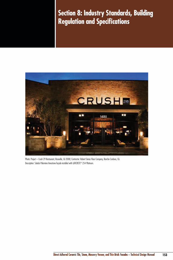
153Direct Adhered Ceramic Tile, Stone, Masonry Veneer, and Thin Brick Facades – Technical Design Manual
Section 8: Industry Standards, Building Regulation and Specifications
153Direct Adhered Ceramic Tile, Stone, Masonry Veneer, and Thin Brick Facades – Technical Design Manual
Photo: Project – Crush 29 Restaurant, Roseville, CA 2008; Contractor: Robert Simas Floor Company, Rancho Cordova, CA.Description: Salado Palomino limestone façade installed with LATICRETE® 254 Platinum.

154 Direct Adhered Ceramic Tile, Stone, Masonry Veneer, and Thin Brick Facades – Technical Design Manual
Section 8: Industry Standards, Building Regulation and Specifications
8.1 BACKGROUNDSince the last printing of this design manual, standards have been adopted to address the installation of adhered veneers. The International Code Council (ICC) publishes the International Building Code (IBC) and International Residential Code (IRC) which were introduced in 2000 to provide more uniform standards in construction around the world. These codes now supersede the codes used until 2000 (e.g. BOCA, ICBO and SBCCI). However, the scope and content of these standards can vary substantially from country to country to allow for differences in construction techniques, design principals and materials.
There are 3 international standards bodies which have created guidelines for tile installation materials. These standard bodies and the standards they have created include;
n American National Standards Institute (ANSI) A108, A118, and A136
n International Organization for Standardization (ISO) 13007-1 to 13007-4
n European Committee for Standardization (EN) 12004, 13888, 14891 and 13813
While the 3 international standards address the performance and use of ceramic tile adhesives, they do not adequately address the special concerns and techniques required for exterior façade applications. Similarly, the international standards for ceramic tile (e.g. ANSI A137.1 and ISO 10545 1–16) are not entirely applicable for stone, masonry veneer or thin brick.
8.2 BUILDING CODESBuilding codes are mandatory laws which either prescribe or set minimum performance criteria for construction in order to protect the health and welfare of the public. Building codes are usually conceived by private, non-governmental organizations that have no legal enforcement powers; these powers rest in local building departments.
Building codes typically are conceived in two distinct formats; a “prescriptive” or a “performance” code. For example, the Building Code Requirements and Specification for Masonry Structures (TMS 402/ACI 530/ASCE 5) code sets a level of performance that direct adhered veneers of ceramic tile, stone or thin brick attain a minimum shear bond strength of
50 psi (0.34 MPa). However, many codes do not prescribe the specific type of adhesive or method of installation required to meet the required performance. In comparison, the technical approval issued by the CSTB in France, known as the AVIS technique, prescribes by law, specific approved individual products and procedures for the direct adhesion of ceramic tile, stone or thin brick as external facade cladding. The Tile Council of North America (TCNA) does provide guidelines for the installation of tile and stone onto exterior veneers in their TCNA Handbook for Ceramic, Glass, and Stone Tile Installation. It is important to consult local building codes that have jurisdiction over a specific project as the requirements of prescriptive codes can change. In addition, the type of finish material used on a project may have different prescriptive criteria.
Building Codes – Adhered VeneerOrganization: International Code Council (ICC) International Building Code – 2009 Section 1405.10
Organization: International Code Council International Residential Code – 2009 Section R703.12
Organizations: The Masonry Society, American Concrete Institute & Structural Engineering Institute Building Code Requirements and Specification for Masonry Structures (TMS 402/ACI 530/ASCE 5) – 2008 Section 6.3
Excerpts and Commentary from International Code Council in IBC and IRC and ACI 530As a guideline, excerpts from the International Building Code, International Residential Code and Building Code Requirements and Specification for Masonry Structures (TMS 402/ACI 530/ASCE 5) – 2008 which regulate direct adhered external cladding of facades are provided below. The current versions of these building codes may not recognize the “state of the art” in construction adhesive technology. Therefore, it is prudent to request special review and approval by building code enforcement officials during the initial design stages of a building if newer technologies and methods are under consideration.
International Building Code (IBC ) – 2009Chapter 14 Exterior Walls

155Direct Adhered Ceramic Tile, Stone, Masonry Veneer, and Thin Brick Facades – Technical Design Manual
Section 8: Industry Standards, Building Regulation and Specifications
Section 1402.1 – DefinitionsExterior Wall – A wall, bearing or non-bearing, that is used as an enclosing wall for a building, other than a fire wall, and that has a slope of 60° (1.05 rad) or greater with the horizontal plane.
Exterior Wall Envelope – A system or assembly of exterior wall components, including exterior wall finish materials, that provides protection of the building structural members, including framing and sheathing materials, and conditioned interior space, from the detrimental effects of the exterior environment.
Adhered Masonry Veneer – Veneer secured and supported through the adhesion of an approved bonding material to an approved backing.
Veneer – A facing attached to a wall for the purpose of providing ornamentation, protection or insulation, but not counted as adding strength to the wall.
Section 1403.2 – Weather Protection – Exterior walls shall provide the building with weather-resistant exterior wall envelope. The exterior wall envelope shall include flashing, as described in Section 1405.4. The exterior wall envelope shall be designed and constructed in such a manner as to prevent the accumulation of water within the wall assembly by providing a water-resistive barrier behind the exterior veneer, as described in Section 1404.2, and a means for draining water that enters the assembly to the exterior.
Section 1403.3 – Structural – Exterior walls, and the associated openings, shall be designed and constructed to resist safely the superimposed loads as required by chapter 16.
Section 1403.4 – Fire resistance – Exterior walls shall be fire resistance rated as required by other sections of this code (IBC) with opening protection as required by Chapter 7.
Section 1404.3 – Wood – Exterior walls of wood construction shall be designed and constructed in accordance with Chapter 23.
Section 1404.4 – Masonry – Exterior walls of masonry construction shall be designed and constructed in accordance with this section and Chapter 21. Masonry units, mortar and metal accessories used in anchored and adhered veneer shall meet the physical requirements of Chapter 21. The backing of anchored and adhered veneer shall be of concrete, masonry, steel framing or wood framing.
Section 1404.5 – Metal – Exterior walls of formed steel construction, structural steel or lightweight metal alloys shall be designed in accordance with Chapter 22 and 20 respectively.
Section 1404.6 – Concrete – Exterior walls of concrete construction shall be designed and constructed in accordance with Chapter 19.
Section 1405.4 – Flashings – Flashing shall be installed in such a manner so as to prevent moisture from entering the wall or to redirect it to the exterior…
Section 1405.10 – Adhered Masonry Veneer – Adhered masonry veneer shall comply with the applicable requirements of Section 1405.10.1 and Sections 6.1 and 6.3 of TMS 402/ACI 530/ASCE 5.
Section 1405.10.1 – Interior Adhered Masonry Veneer – Interior adhered masonry veneers shall have a maximum weight of 20 psf (98.2 kg/m2) and shall be installed in accordance with Section 1405.10. When the interior adhered masonry veneer is supported by wood construction, the supporting members shall be designed to limit deflection to 1/600 of the span of the supporting members.
International Residential Code (IRC) – 2009Chapter 7 Wall Covering
Section R703.12 – Adhered Masonry Veneer Installation – Adhered masonry veneer shall be installed in accordance with the manufacturer’s instructions.
Building Code Requirements and Specification for Masonry Structures (TMS 402/ACI 530/ASCE 5) – 2008Section 6.3.2 – Prescriptive requirements for adhered masonry veneer –
Section 6.3.2.1 – Unit Sizes – Adhered veneer units shall not exceed 2-5/8" (67 mm) in specified thickness, 36" (914 mm) in any face dimension, nor more than 5 ft2 (0.46 m2) in total face area, and shall not weigh more than 15 psf (73.6 kg/m2).
Section 6.3.2.2 – Wall Area Limitations – The height, length and area of adhered veneer shall not be limited except as required to control restrained differential movement stresses between veneer and backing.
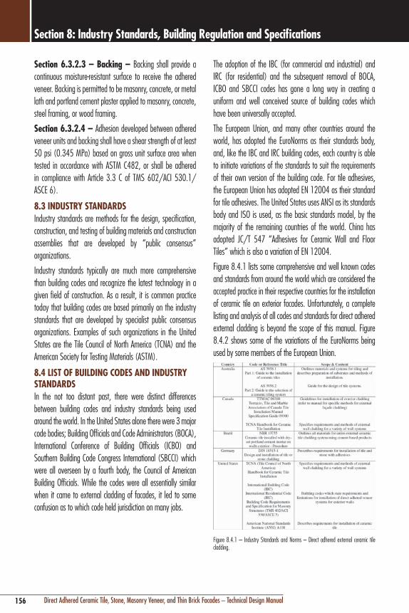
156 Direct Adhered Ceramic Tile, Stone, Masonry Veneer, and Thin Brick Facades – Technical Design Manual
Section 8: Industry Standards, Building Regulation and Specifications
Section 6.3.2.3 – Backing – Backing shall provide a continuous moisture-resistant surface to receive the adhered veneer. Backing is permitted to be masonry, concrete, or metal lath and portland cement plaster applied to masonry, concrete, steel framing, or wood framing.
Section 6.3.2.4 – Adhesion developed between adhered veneer units and backing shall have a shear strength of at least 50 psi (0.345 MPa) based on gross unit surface area when tested in accordance with ASTM C482, or shall be adhered in compliance with Article 3.3 C of TMS 602/ACI 530.1/ASCE 6).
8.3 INDUSTRY STANDARDSIndustry standards are methods for the design, specification, construction, and testing of building materials and construction assemblies that are developed by “public consensus” organizations.
Industry standards typically are much more comprehensive than building codes and recognize the latest technology in a given field of construction. As a result, it is common practice today that building codes are based primarily on the industry standards that are developed by specialist public consensus organizations. Examples of such organizations in the United States are the Tile Council of North America (TCNA) and the American Society for Testing Materials (ASTM).
8.4 LIST OF BUILDING CODES AND INDUSTRY STANDARDSIn the not too distant past, there were distinct differences between building codes and industry standards being used around the world. In the United States alone there were 3 major code bodies; Building Officials and Code Administrators (BOCA), International Conference of Building Officials (ICBO) and Southern Building Code Congress International (SBCCI) which were all overseen by a fourth body, the Council of American Building Officials. While the codes were all essentially similar when it came to external cladding of facades, it led to some confusion as to which code held jurisdiction on many jobs.
The adoption of the IBC (for commercial and industrial) and IRC (for residential) and the subsequent removal of BOCA, ICBO and SBCCI codes has gone a long way in creating a uniform and well conceived source of building codes which have been universally accepted.
The European Union, and many other countries around the world, has adopted the EuroNorms as their standards body, and, like the IBC and IRC building codes, each country is able to initiate variations of the standards to suit the requirements of their own version of the building code. For tile adhesives, the European Union has adopted EN 12004 as their standard for tile adhesives. The United States uses ANSI as its standards body and ISO is used, as the basic standards model, by the majority of the remaining countries of the world. China has adopted JC/T 547 “Adhesives for Ceramic Wall and Floor Tiles” which is also a variation of EN 12004.
Figure 8.4.1 lists some comprehensive and well known codes and standards from around the world which are considered the accepted practice in their respective countries for the installation of ceramic tile on exterior facades. Unfortunately, a complete listing and analysis of all codes and standards for direct adhered external cladding is beyond the scope of this manual. Figure 8.4.2 shows some of the variations of the EuroNorms being used by some members of the European Union.
Figure 8.4.1 – Industry Standards and Norms – Direct adhered external ceramic tile cladding.

157Direct Adhered Ceramic Tile, Stone, Masonry Veneer, and Thin Brick Facades – Technical Design Manual
Section 8: Industry Standards, Building Regulation and Specifications
Figure 8.4.2 – Variations of EN 12004 Tile Adhesive Standards for some European Union countries.
8.5 SAMPLE GUIDE SPECIFICATIONS For a complete library of LATICRETE specifications, please visit www.laticrete.com/ag.
Guide Specification – Concrete Masonry or Uneven Concrete (ES-W211E)PART 1 – GENERAL1.1 SummaryA. Scope of Work – Provide ceramic tile, tile installation
materials and accessories as indicated on drawings, as specified herein, and as needed for complete and proper installation.
B. Related Documents – Provisions within General and Supplementary General Conditions of the Contract, Division 1 – General Requirements, and the Drawings apply to this Section.
1.2 Section IncludesA. Masonry veneer units
B. Porcelain tile
C. Installation Products; adhesives, mortars, pointing mortars, and sealants
D. Waterproofing membranes for ceramic tile work
E. Anti-fracture membranes for ceramic tile work
F. Thresholds, trim, cementitious backer units and other accessories specified herein.
NOTE TO SPECIFIER: Edit for applicable procedures and materials.
1.3 Products Furnished but not Installed Under This SectionNOTE TO SPECIFIER: Edit for applicable products.
1.4 Products Installed but not Furnished Under This SectionNOTE TO SPECIFIER: Edit for applicable products.
1.5 Environmental Performance RequirementsA. Environmental Performance Criteria: The following criteria
are required for products included in this section.
Refer to Division 1 for additional requirements:
1. Products manufactured regionally within a 500 mile radius of the Project site;
2. Adhesive products must meet or exceed the VOC limits of South Coast Air Quality Management District Rule #1168 and Bay Area Resources Board Reg. 8, Rule 51.
1.6 Related SectionsA. Section 03 30 00 Cast-in-Place Concrete (monolithic slab
finishing for ceramic tile)
B. Section 03 39 00 Concrete Curing
C. Section 03 41 00 Pre-cast Structural Concrete
D. Section 03 53 00 Concrete Topping
E. Section 04 22 00 Concrete Unit Masonry
F. Section 04 40 00 Stone Assemblies
G. Section 04 70 00 Manufactured Masonry
H. Section 05 12 00 Structural Steel Framing
I. Section 06 11 00 Wood Framing
J. Section 07 14 00 Fluid-applied Waterproofing
K. Section 07 92 13 Elastomeric Joint Sealants
L. Section 09 21 00 Gypsum Board Assemblies
M. Section 09 30 33 Stone Tiling
NOTE TO SPECIFIER: Above are examples of typical broad scope and narrow scope sections related to ceramic tile installation. Edit for applicable related sections.
1.7 AllowancesNOTE TO SPECIFIER: Edit for detail of applicable ALLOWANCES; coordinate with Section 01 21 00 Allowances. Allowances in the form of unit pricing are sometimes used when the scope of the tile work at time of bid is undetermined.
1.8 AlternatesNOTE TO SPECIFIER: Edit for applicable ALTERNATES. Alternates may be used to evaluate varying levels of performance of setting systems or to assist in the selection of the tile by economy.

158 Direct Adhered Ceramic Tile, Stone, Masonry Veneer, and Thin Brick Facades – Technical Design Manual
Section 8: Industry Standards, Building Regulation and Specifications
1.9 Reference StandardsA. American Iron and Steel Institute (AISI) Specification for the
Design of Cold-Formed Steel Structural Members
B. American National Standards Institute (ANSI) A137.1 American National Standard Specifications For Ceramic Tile
C. American National Standards Institute (ANSI) A108.01 – A108.17 American National Standard Specifications For The Installation Of Ceramic Tile
D. American National Standards Institute (ANSI) A118.1 – A118.13 American National Standard Specifications For The Installation Of Ceramic Tile
E. American National Standards Institute (ANSI) A136.1 American National Standard Specifications For The Installation Of Ceramic Tile
F. American Plywood Association (APA) Y510T Plywood Design Specifications
G. American Society For Testing And Materials (ASTM) A82 Standard Specification for Steel Wire, Plain, for Concrete Reinforcement
H. American Society For Testing And Materials (ASTM) A185 Standard Specification for Steel Welded Wire Fabric, Plain, for Concrete Reinforcement
I. American Society For Testing And Materials (ASTM) C33 Standard Specification for Concrete Aggregate
J. American Society For Testing And Materials (ASTM) C36 Standard Specification for Gypsum Wallboard
K. American Society For Testing And Materials (ASTM) C91 Standard Specification for Masonry Cement
L. American Society For Testing And Materials (ASTM) C109 Standard Test Method for Compressive Strength of Hydraulic Cement Mortars (Using 2" or 50 mm Cube Specimens)
M. American Society For Testing And Materials (ASTM) C144 Standard Specification for Aggregate for Masonry Mortar
N. American Society For Testing And Materials (ASTM) C150 Standard Specification for Portland Cement
O. American Society For Testing And Materials (ASTM) C171 Standard Specification for Sheet Materials for Curing Concrete
P. American Society For Testing And Materials (ASTM) C241 Standard Test Method for Abrasion Resistance of Stone Subjected to Foot Traffic
Q. American Society For Testing And Materials (ASTM) C267 Standard Test Method for Chemical Resistance of Mortars, Grouts, and Monolithic Surfacings
R. American Society For Testing And Materials (ASTM) C270 Standard Specification for Mortar for Unit Masonry
S. American Society For Testing And Materials (ASTM) C482 Standard Test Method for Bond Strength of Ceramic Tile to Portland Cement
T. American Society For Testing And Materials (ASTM) C503 Standard Specification for Marble Dimension Stone (Exterior)
U. American Society For Testing And Materials (ASTM) C531 Standard Test Method for Linear Shrinkage and Coefficient of Thermal Expansion of Chemical-Resistant Mortars, Grouts, Monolithic Surfacings and Polymer Concretes
V. American Society For Testing And Materials (ASTM) C627 Standard Test Method for Evaluating Ceramic Floor Tile Installation Systems Using the Robinson-Type Floor Tester
W. American Society For Testing And Materials (ASTM) C794 Standard Test Method for Adhesion-in-Peel of Elastomeric Joint Sealants
X. American Society For Testing And Materials (ASTM) C847 Standard Specification for Metal Lath
Y. American Society For Testing And Materials (ASTM) C905 Standard Test Method for Apparent Density of Chemical-Resistant Mortars, Grouts, and Monolithic Surfacings
Z. American Society For Testing And Materials (ASTM) C920 Standard Specification for Elastomeric Joint Sealants
AA. American Society For Testing And Materials (ASTM) C955 Standard Specification for Load Bearing (Transverse and Axial) Steel Studs, Runners (Tracks), and Bracing or Bridging for Screw Application of Gypsum Board and Metal Plaster Bases
BB. American Society For Testing And Materials (ASTM) D226 Standard Specification for Asphalt-Saturated Organic Felt Used in Roofing And Waterproofing

159Direct Adhered Ceramic Tile, Stone, Masonry Veneer, and Thin Brick Facades – Technical Design Manual
Section 8: Industry Standards, Building Regulation and Specifications
PP. American Society For Testing And Materials (ASTM) E492 Standard Test Method for Laboratory Measurement of Impact Sound Transmission Through Floor-Ceiling Assemblies Using the Tapping Machine
QQ. American Society For Testing And Materials (ASTM) E989 Standard Classification for Determination of Impact Insulation Class (IIC)
RR. American Society of Mechanical Engineers (ASME) – ASME A112.6.3 Floor and Trench Drains
SS. Canadian Sheet Steel Building Institute (CSSBI) Lightweight Steel Framing Binder {Publication 52M}
TT. Federal Housing Administration (FHA) Bulletin No. 750 Impact Noise Control in Multifamily Dwellings
UU. Housing and Urban Development (HUD) TS 28 A Guide to Airborne, Impact and Structure-borne Noise-Control in Multifamily Dwellings
VV. Masonry Veneer Manufacturers Association (MVMA) Installation Guide for Adhered Concrete Masonry Veneer
WW. Materials And Methods Standards Association (MMSA) Bulletins 1 – 16
XX. Metal Lath/Steel Framing Association (ML/SFA) 540 Lightweight Steel Framing Systems Manual
YY. Steel Stud Manufacturers Association (SSMA) Product Technical Information and ICBO Evaluation Service, Inc. Report ER-4943P
ZZ. Terrazzo, Tile And Marble Association Of Canada (TTMAC) Specification Guide 09 30 00 Tile Installation Manual
AAA. Tile Council Of North America (TCNA) Handbook For Ceramic, Glass, and Stone Tile Installation
NOTE TO SPECIFIER: Edit for applicable reference standards.
1.10 System DescriptionA. Manufactured masonry veneer using latex-modified portland
cement mortar and latex portland cement grout joints.
NOTE TO SPECIFIER: The above systems are example descriptions; edit for additional applicable systems.
CC. American Society For Testing And Materials (ASTM) D227 Standard Specification for Coal-Tar Saturated Organic Felt Used in Roofing and Waterproofing
DD. American Society For Testing And Materials (ASTM) D751 Standard Test Method for Coated Fabrics
EE. American Society For Testing And Materials (ASTM) D751 Standard Test Method for Rubber Property – Durometer Hardness
FF. American Society For Testing And Materials (ASTM) D1248 Standard Test Method for Staining of Porous Substances by Joint Sealants
GG. American Society For Testing And Materials (ASTM) D2240 Standard Test Method for Coated Fabrics
HH. American Society For Testing And Materials (ASTM) D4068 Standard Specification for Chlorinated Polyethylene (CPE) Sheeting for Concealed Water-Containment Membrane
II. American Society For Testing And Materials (ASTM) D4263 Standard Test Method for Indicating Moisture in Concrete by The Plastic Sheet Method
JJ. American Society For Testing And Materials (ASTM) D4397 Standard Specification for Polyethylene Sheeting for Construction, Industrial and Agricultural Applications
KK. American Society For Testing And Materials (ASTM) D4716 Standard Test Method for Determining the (In Plane) Flow Rate Per Unit Width and Hydraulic Transmissivity of a Geo-synthetic Using a Constant Head
LL. American Society For Testing And Materials (ASTM) E84 Standard Test Method for Surface Burning Characteristics of Building Materials
MM. American Society For Testing And Materials (ASTM) E90 Standard Test Method for Laboratory Measurement of Airborne Sound Transmission Loss of Building Partitions
NN. American Society For Testing And Materials (ASTM) E96 Standard Test Methods for Water Vapor Transmission of Materials
OO. American Society For Testing And Materials (ASTM) E413 Standard Classification for Rating Sound Insulation

160 Direct Adhered Ceramic Tile, Stone, Masonry Veneer, and Thin Brick Facades – Technical Design Manual
Section 8: Industry Standards, Building Regulation and Specifications
3. LEED Construction Guide for Green Building Design and Construction, 2009 Edition Credit MR 2.1: (Divert 50% from Disposal) Manufacturer’s packaging showing recycle symbol for appropriate disposition in construction waste management.
4. LEED Construction Guide for Green Building Design and Construction, 2009 Edition Credit MR 2.1: (Divert 75% from Disposal) Manufacturer’s packaging showing recycle symbol for appropriate disposition in construction waste management.
5. LEED Construction Guide for Green Building Design and Construction, 2009 Edition Credit MR 4.1: Manufacturer’s product data showing post-consumer and/or pre- consumer recycled content.
6. LEED Construction Guide for Green Building Design and Construction, 2009 Edition Credit MR 4.2: Manufacturer’s product data showing post-consumer and/or pre- consumer recycled content.
7. LEED Construction Guide for Green Building Design and Construction, 2009 Edition Credit MR 5.1: 10% Extracted, Processed and Manufactured Regionally): Product data indicating location of material manufacturer for regionally manufactured materials.
a. Include statement indicating cost and distance from manufacturer to Project for each regionally manufactured product.
8. LEED Construction Guide for Green Building Design and Construction, 2009 Edition Credit MR 5.2: 20% Extracted, Processed & Manufactured Regionally): Product data indicating location of material manufacturer for regionally manufactured materials.
a. Include statement indicating cost and distance from manufacturer to Project for each regionally manufactured product.
9. LEED Schools Reference Guide (Educational Projects Only), 2007 Edition Credit EQ 9 (Enhanced Acoustical Performance): Impact noise reduction test reports and product data on sound control product(s).
10. LEED Schools Reference Guide (Educational Projects Only), 2007 Edition Credit EQ 10 (Mold Prevention): Manufacturer’s packaging and/or data showing anti-microbial protection in product(s).
1.11 SubmittalsNOTE TO SPECIFIER: Edit for applicable requirements.
A. Submittal Requirements: Submit the following “Required LEED Criteria” certification items as listed below. Refer to Division 1 for additional requirements:
1. A completed LEED Environmental Building Materials Certification Form. Information to be supplied generally includes:
a. Manufacturing plant locations for tile installation products.
b. LEED Credits as listed in Part 1.4B “LEED Credit Submittals”
2. GREENGUARD Environmental Institute certificates or GreenGuard Environmental Institute Children & Schools certificates provided by the tile installation materials manufacturer on GREENGUARD letterhead stating “This product has been GREENGUARD Indoor Air Quality Certified® by the GREENGUARD Environmental Institute under the GREENGUARD Standard for Low Emitting Products” for each tile installation product used to verify Low VOC product information.
3. Contractor’s certification of LEED Compliance: Submit Contractor’s certification verifying the installation of specified LEED Compliant products.
4. Product Cut Sheets for all materials that meet the LEED performance criteria. Submit Product Cut Sheets with Contractor or Subcontractor’s stamp, as confirmation that submitted products were installed on Project.
5. Material Safety Data Sheets for all applicable products.
B. LEED Credit Submittals for the following;
1. LEED Construction Guide for Green Building Design and Construction, 2009 Edition Credit EQ 4.1: Manufacturer’s product data for tile installation materials, including GREENGUARD Certificate on GREENGUARD letterhead stating product VOC content.
2. LEED Construction Guide for Green Building Design and Construction, 2009 Edition Credit EQ 4.3: Manufacturer’s product data for tile installation materials, including GREENGUARD Certificate on GREENGUARD letterhead stating product VOC content.
161Direct Adhered Ceramic Tile, Stone, Masonry Veneer, and Thin Brick Facades – Technical Design Manual
Section 8: Industry Standards, Building Regulation and Specifications
minimum experience and ISO 9001-2008 certification. Obtain installation materials from single source manufacturer to insure consistent quality and full compatibility.
C. Submit laboratory confirmation of adhesives, mortars, grouts and other installation materials:
1. Identify proper usage of specified materials using positive analytical method.
2. Identify compatibility of specified materials using positive analytical method.
3. Identify proper color matching of specified materials using a positive analytical method.
D. Installer qualifications: company specializing in installation of manufactured masonry veneer, mosaics, thin brick, and/or pavers with five (5) years documented experience with installations of similar scope, materials and design.
1.13 Mock-UpsA. Provide mock-up of each type/style/finish/size/color of
manufactured masonry veneer, mosaics, thin brick, and pavers along with respective installation adhesives, mortars, pointing mortars, grouts and other installation materials, under provisions of Section (014300) (014500).
1. Construct areas designated by Architect.
2. Do not proceed with remaining work until material, details and workmanship are approved by Architect.
3. Refinish mock-up area as required to produce acceptable work.
4. As approved by Architect, mock-up may be incorporated into finished work.
1.14 Pre-Installation ConferencePre-installation conference: At least three weeks prior to commencing the work attend a meeting at the jobsite to discuss conformance with requirements of specification and job site conditions. Representatives of owner, architect, general contractor, tile subcontractor, Tile Manufacturer, Installation System Manufacturer and any other parties who are involved in the scope of this installation must attend the meeting.
C. Submit shop drawings and manufacturers' product data under provisions of Section (013300).
D. Submit samples of each type/style/finish/size/color of manufactured masonry veneer, mosaics, thin brick, and paver under provisions of Section (013300).
E. Submit manufacturers' installation instructions under provisions of Section (013300).
F. Submit manufacturer's qualifications under provisions of Section (014000) that the materials supplied conform to relevant standards.
G. Submit proof of warranty under provisions of Section (017800).
H. Submit sample of installation system demonstrating compatibility/functional relationships between adhesives, mortars, grouts and other components under provision of Section (013300) (014300). Submit proof from veneer manufacturer or supplier verifying suitability of veneer for specific application and use; including dimensional stability, water absorption, freeze/thaw resistance (if applicable), resistance to thermal cycling, and other characteristics that the may project may require. These characteristics must be reviewed and approved by the project design professional(s).
I. Submit list from manufacturer of installation system/adhesive/mortar/grout identifying a minimum of three (3) similar projects, each with a minimum of ten (10) years service.
J. For alternate materials, at least thirty (30) days before bid date submit independent laboratory test results confirming compliance with specifications listed in Part 2 – Products.
1.12 Quality AssuranceA. Manufactured Masonry Veneer or Thin Brick manufacturer
(single source responsibility): Company specializing in manufactured masonry veneer or thin brick products with three (3) years minimum experience. Obtain veneer units from a single source with resources to provide products of consistent quality in appearance and physical properties.
B. Installation System Manufacturer (single source responsibility): Company specializing in adhesives, mortars, grouts and other installation materials with ten (10) years

162 Direct Adhered Ceramic Tile, Stone, Masonry Veneer, and Thin Brick Facades – Technical Design Manual
Section 8: Industry Standards, Building Regulation and Specifications
1.17 Sequencing and SchedulingA. Coordinate installation of tile work with related work.
B. Proceed with tile work only after curbs, vents, drains, piping, and other projections through substrate have been installed and when substrate construction and framing of openings have been completed.
NOTES FOR SPECIFIER: Edit for project specific sequence and scheduling.
1.18 WarrantyThe Contractor warrants the work of this Section to be in accordance with the Contract Documents and free from faults and defects in materials and workmanship for a period of 25 years. The manufacturer of adhesives, mortars, pointing mortars, and other installation materials shall provide a written twenty five (25) year warranty, which covers materials and labor – reference LATICRETE® Warranty Data Sheet 025.0 for complete details and requirements. For exterior facades over steel or wood framing, the manufacturer of adhesives, mortars, grouts and other installation materials shall provide a written fifteen (15) year warranty, which covers replacement of LATICRETE products only – reference LATICRETE Warranty Data Sheet 230.15MVIS for complete details and requirements.
1.19 MaintenanceSubmit maintenance data under provisions of Section (017800) (019300). Include cleaning methods, cleaning solutions recommended, stain removal methods, as well as polishes and waxes recommended.
1.20 Extra Materials StockUpon completion of the work of this Section, deliver to the Owner 2% minimum additional veneer units in the shape of each type, color, pattern and size used in the Work, as well as extra stock of adhesives, mortars, pointing mortars and other installation materials for the Owner's use in replacement and maintenance. Extra stock is to be from same production run or batch as original veneer units and installation materials.
PART 2 – PRODUCTS2.1 Manufactured Masonry Veneer or Thin Brick ManufacturersSubject to compliance with paragraphs 1.12 and performance requirements, provide products by one of the following manufacturers:
1.15 Delivery, Storage and HandlingA. Acceptance at Site: deliver and store packaged materials in
original containers with seals unbroken and labels, including grade seal, intact until time of use, in accordance with manufacturer's instructions.
B. Store ceramic tile and installation system materials in a dry location; handle in a manner to prevent chipping, breakage, and contamination.
C. Protect latex additives, organic adhesives, epoxy adhesives and sealants from freezing or overheating in accordance with manufacturer's instructions; store at room temperature when possible.
D. Store portland cement mortars and grouts in a dry location.
1.16 Project/Site ConditionsA. Provide ventilation and protection of environment as
recommended by manufacturer.
B. Prevent carbon dioxide damage to ceramic tile, mosaics, pavers, trim, thresholds, as well as adhesives, mortars, grouts and other installation materials, by venting temporary heaters to the exterior.
C. Maintain ambient temperatures not less than 50ºF (10ºC) or more than 100ºF (38ºC) during installation and for a minimum of seven (7) days after completion. Setting of portland cement is retarded by low temperatures. Protect work for extended period of time and from damage by other trades. Installation with latex portland cement mortars requires substrate, ambient and material temperatures at least 37ºF (3ºC). There should be no ice in slab. Freezing after installation will not damage latex portland cement mortars. Protect portland cement based mortars and grouts from direct sunlight, radiant heat, forced ventilation (heat & cold) and drafts until cured to prevent premature evaporation of moisture. Epoxy mortars and grouts require surface temperatures between 60ºF (16ºC) and 90ºF (32ºC) at time of installation. It is the General Contractor’s responsibility to maintain temperature control.

163Direct Adhered Ceramic Tile, Stone, Masonry Veneer, and Thin Brick Facades – Technical Design Manual
Section 8: Industry Standards, Building Regulation and Specifications
2.6 Performance Specification – Tile Installation AccessoriesA. Waterproofing/Crack Suppression Membrane to be thin,
cold applied, single component liquid and load bearing. Reinforcing fabric to be non-woven rot-proof specifically intended for waterproofing membrane. Waterproofing Membrane to be non-toxic, non-flammable, and non-hazardous during storage, mixing, application and when cured. It shall be certified by IAPMO and ICC approved as a shower pan liner and shall also meet the following physical requirements:
1. Hydrostatic Test (ASTM D4068): Pass
2. Elongation at break (ASTM D751): 20–30%
3. System Crack Resistance (ANSI A118.12): Pass (High)
4. 7 day Tensile Strength (ANSI A118.10): >265 psi (1.8 MPa)
5. 7 day Shear Bond Strength (ANSI A118.10): >200 psi (1.4 MPa)
6. 28 Day Shear Bond Strength (ANSI A118.4): >214 psi (1.48 – 2.4 MPa)
7. Service Rating (TCA/ASTM C627): Extra Heavy
8. Total VOC Content: < 0.05 mg/m3
B. Epoxy Waterproofing Membrane to be 3 component epoxy, trowel applied specifically designed to be used under ceramic tile, stone or brick and requires only 24 hours prior to flood testing:
1. Breaking Strength (ANSI A118.10): 450–530 psi (3.1–3.6 MPa)
2. Waterproofness (ANSI A118.10): No Water penetration
3. 7 day Shear Bond Strength (ANSI A118.10): 110 – 150 psi (0.8 – 1 MPa)
4. 28 Day Shear Bond Strength (ANSI A118.10): 90 – 120 psi (0.6 – 0.83 MPa)
5. 12 Week Shear Bond Strength (ANSI A118.10): 110 – 130 psi (0.8 – 0.9 MPa)
6. Total VOC Content: <3.4 g/l C. Wire Reinforcing: 2" x 2" (50 x 50 mm) x 16 ASW gauge
or 0.0625" (1.6 mm) diameter galvanized steel welded wire mesh complying with ANSI A108.02 3.7, ASTM A185 and ASTM A82.
NOTE TO SPECIFIER: Provide list of acceptable tile manufacturers.
2.2 Manufactured Masonry Veneer Materials NOTE TO SPECIFIER: Edit for each tile type.
A. Manufactured Masonry Veneer
B. Grade:
C. Size:
D. Edge
E. Finish:
F. Color
G. Special shapes
H. Location:
2.3 Thin Brick Materials NOTE TO SPECIFIER: Edit for each tile type.
A. Thin Brick
B. Grade:
C. Size:
D. Edge
E. Finish:
F. Color
G. Special shapes
H. Location:
2.5 Veneer Installation Materials ManufacturerA. LATICRETE International, Inc. 1 LATICRETE Park North, Bethany, CT 06524-3423 USA Phone 800.243.4788, +1.203.393.0010 [email protected] www.laticrete.com; www.laticrete.com/green
NOTE TO SPECIFIER: Use either the following performance specification or the proprietary specification.

164 Direct Adhered Ceramic Tile, Stone, Masonry Veneer, and Thin Brick Facades – Technical Design Manual
Section 8: Industry Standards, Building Regulation and Specifications
3. Weather Resistance (QUV Weather-ometer): 10000 hours (no change)
F. Spot Bonding Epoxy Adhesive for installing tile, brick and stone over vertical and overhead surfaces shall be high strength, high temperature resistant, non-sag and shall meet the following physical requirements:
4. Thermal Shock Resistance (ANSI A118.3): >1000 psi (6.9 MPa)
5. Water Absorption (ANSI A118.3): 0.1 %
1. Compressive Strength (ANSI A118.3): >8300 psi (57.2 MPa)
2. Shear Bond Strength (ANSI A118.3 Modified): >730 psi (5 MPa)
NOTE TO SPECIFIER: Edit applicable tile installation materials.
2.8 Proprietary Specification – Tile Installation AccessoriesInstallation accessories as manufactured by LATICRETE International, Inc. 1 LATICRETE Park North Bethany, CT 06524-3423 USA Phone 800.243.4788 www.laticrete.com
A. Waterproofing Membrane: LATICRETE® Hydro Ban®** as manufactured by LATICRETE International, Inc.
B. Epoxy Waterproofing Membrane: LATAPOXY® Waterproof Flashing Mortar as manufactured by LATICRETE International, Inc.
NOTE TO SPECIFIER: Edit applicable tile installation accessories.
Proprietary Specification – Tile Installation MaterialsInstallation materials as manufactured by LATICRETE International, Inc. 1 LATICRETE Park North Bethany, CT 06524-3423 USA Phone 800.243.4788 www.laticrete.com; www.laticrete.com/green
A. Latex Portland Cement Mortar for thick beds, screeds, leveling beds and scratch/plaster coats: LATICRETE Premium Mortar Bed as manufactured by LATICRETE International, Inc.
D. Cleavage membrane: 15 pound asphalt saturated, non-perforated roofing felt complying with ASTM D226, 15 pound coal tar saturated, non-perforated roofing felt complying with ASTM D227 or 4.0 mils (0.1 mm) thick polyethylene plastic film complying with ASTM D4397.
E. Cementitious backer board units: size and thickness as specified, complying with ANSI A118.9.
F. Thresholds: Provide marble saddles complying with ASTM C241 for abrasion resistance and ASTM C503 for exterior use, in color, size, shape and thickness as indicated on drawings.
NOTE TO SPECIFIER: Edit applicable tile installation accessories.
2.7 Performance Specification – Tile Installation MaterialsA. Latex Portland Cement Mortar for thick beds, screeds,
leveling beds and scratch/plaster coats to be weather, frost, shock resistant and meet the following physical requirements:
1. Compressive Strength (ANSI A118.7 Modified): >4000 psi (27.6 MPa)
2. Total VOC Content: < 0.05 mg/m3
B. Latex Portland Cement Thin Bed Mortar for thin set and slurry bond coats to be weather, frost, shock resistant, non-flammable and meet the following physical requirements:
1. Compressive strength (ASTM C270): >2400 psi (16.5 MPa)
2. Total VOC Content: < 0.05 mg/m3
C. Latex Portland Cement Pointing Mortar to be weather, frost and shock resistant, as well as meet the following physical requirements:
1. Compressive Strength (ASTM C91): >3000 psi (20.7 MPa)
2. Total VOC Content: < 0.05 mg/m3
E. Expansion and Control Joint Sealant to be a one component, neutral cure, exterior grade silicone sealant and meet the following requirements:
1. Tensile Strength (ASTM C794): 280 psi (1.9 MPa)
2. Hardness (ASTM D751; Shore A): 25 (colored sealant)/15 (clear sealant)

165Direct Adhered Ceramic Tile, Stone, Masonry Veneer, and Thin Brick Facades – Technical Design Manual
Section 8: Industry Standards, Building Regulation and Specifications
stone, where L is the clear span length of the supporting member per applicable building code;
3. Clean and free of dust, dirt, oil, grease, sealers, curing compounds, laitance, efflorescence, form oil, loose plaster, paint, and scale.
4. For thin-bed ceramic tile installations when a cementitious bonding material will be used, including medium bed mortar: maximum allowable variation in the tile substrate – for tiles with edges shorter than 15" (375 mm), maximum allowable variation is 1/4" in 10' (6 mm in 3 m) from the required plane, with no more than 1/16" variation in 12" (1.5 mm variation in 300 mm) when measured from the high points in the surface. For tiles with at least one edge 15" (375 mm) in length, maximum allowable variation is 1/8" in 10' (3 mm in 3 m) from the required plane, with no more than 1/16" variation in 24" (1.5 mm variation in 600 mm) when measured from the high points in the surface. For modular substrate units, such as exterior glue plywood panels or adjacent concrete masonry units, adjacent edges cannot exceed 1/32" (0.8 mm) difference in height. Should the architect/designer require a more stringent finish tolerance (e.g. 1/8" in 10' [3 mm in 3 m]), the subsurface specification must reflect that tolerance, or the tile specification must include a specific and separate requirement to bring the subsurface tolerance into compliance with the desired tolerance. For thick bed (mortar bed) ceramic and stone tile installations and self-leveling methods: maximum allowable variation in the installation substrate to be 1/4" in 10' (6 mm in 3 m);
5. To fully evacuate water, shower pan membranes and bonded waterproofing membranes in wet areas must slope to and connect with a drain. Plumbing code typically requires membranes to be sloped a minimum of 1/4" per ft (6 mm per 300 mm) and extend at least 3" (75 mm) above the height of the curb or threshold. Account for the perimeter floor height required to form adequate slopes. Membranes must be installed over the other horizontal surfaces in wet areas subject to deterioration, like shower seats. They must be sloped and configured so as to direct water to the membrane connected to the drain. The weep
B. Latex Portland Cement Thin Bed Mortar: LATICRETE Hi-Bond Masonry Veneer Mortar as manufactured by LATICRETE International, Inc.
C. Latex Portland Cement Grout: LATICRETE Premium Masonry Pointing Mortar as manufactured by LATICRETE International, Inc.
D. Expansion and Control Joint Sealant: LATICRETE Latasil™ as manufactured by LATICRETE International, Inc.
E. Spot Bonding Epoxy Adhesive: LATAPOXY 310 Stone Adhesive (Standard or Rapid Grade) as manufactured by LATICRETE International, Inc.
** GREENGUARD Indoor Air Quality Certified® and GREENGUARD for Schools & Children Indoor Air Quality Certified Product
PART 3 – EXECUTION3.1 Substrate ExaminationA. Verify that surfaces to be covered with ceramic tile, mosaics, pavers, brick, masonry veneer, stone, trim or waterproofing are:
1. Sound, rigid and conform to good design/engineering practices;
2. Systems, including the framing system and panels, over which tile or stone will be installed shall be in conformance with the International Residential Code (IRC) for residential applications, the International Building Code (IBC) for commercial applications, or applicable building codes. The project design should include the intended use and necessary allowances for the expected live load, concentrated load, impact load, and dead load including the weight of the finish and installation materials. In addition to deflection considerations, above-ground installations are inherently more susceptible to vibration. Consult grout, mortar, and membrane manufacturer to determine appropriate installation materials for above-ground installations. A crack isolation membrane and higher quality setting materials can increase the performance capabilities of above-ground applications. However, the upgraded materials cannot mitigate structural deficiencies including floors not meeting code requirements and/or over loading or other abuse of the installation in excess of design parameters. Maximum allowable floor member live load and concentrated load deflection shall not exceed L/360 for tile, or, L/480 for

166 Direct Adhered Ceramic Tile, Stone, Masonry Veneer, and Thin Brick Facades – Technical Design Manual
Section 8: Industry Standards, Building Regulation and Specifications
(Insert any Special Means of Preparation in addition to the surface preparation requirements listed in §3.1;…)
NOTE TO SPECIFIER: Edit substrate and preparation section based on project specific surfaces and conditions.
3.3 Installation – AccessoriesNOTE TO SPECIFIER: Edit section based on project conditions.
3.4 Installation – Tile, Brick, Masonry Veneer, and StoneA. General: Install in accordance with current versions of
American National Standards Institute, Inc. (ANSI) “A108 American National Standard Specifications for Installation of Ceramic Tile” and TCNA “Handbook for Ceramic, Glass, and Stone Tile Installation” Cut and fit ceramic tile, glass tile, masonry veneer, brick or stone neatly around corners, fittings, and obstructions. Perimeter pieces to be minimum half tile, brick or stone. Chipped, cracked, split pieces and edges are not acceptable. Make joints even, straight, plumb and of uniform width to tolerance +/- 1/16" over 8' (1.5 mm in 2.4 m). Install divider strips at junction of flooring and dissimilar materials. When glass tile is used, consult glass tile manufacturer for membrane options and recommendations. Where installation will be subjected to freeze/thaw cycles, snow and ice accumulation, and/or snow melting chemicals, degradation can occur over time.
B. Pre-float Method: Over clean, dimensionally stable and sound concrete or masonry substrates, apply thick-bed mortar, or, thin-set mortar as scratch/leveling coat in compliance with current revision of A108.1A (1.0, 1.4 and 5.1). Float surface of scratch/leveling coat plumb, true and allow mortar to set until firm. For installation of ceramic tile, mosaic, paver, brick or stone, follow Thin Bed Method (§3.4E).
Use the following LATICRETE® System Materials: LATICRETE 3701 Fortified Mortar Bed
LATICRETE 254 Platinum
References:LATICRETE Data Sheets: 100.0; 677.0
LATICRETE MSDS: 3701FMB; 254
GREENGUARD Certificates: 3701 FMB; 254
LATICRETE Technical Data Sheets: 105, 106, 114, 118, 122, 128, 130, 143, 199, 204
holes of clamping ring drains enable water to pass from the membrane into the plumbing system. Crushed stone or tile, or other positive weep protectors, placed around/over weep holes help prevent their blockage. To form a watertight seal, membranes must have adequate contact with the clamping ring of the drain or with the bonding area of an integrated bonding flange;
6. Not leveled with gypsum or asphalt based compounds; For substrates scheduled to receive a waterproofing and/or crack isolation membrane, maximum amount of moisture in the concrete/mortar bed substrate should not exceed 5 lbs/1,000 ft2/24 hours (283 µg/s•m2) per ASTM F1869 or 75% relative humidity as measured with moisture probes per ASTM F2170. Consult with finish materials manufacturer to determine the maximum allowable moisture content for substrates under their finished material. Please refer to LATICRETE® TDS 183 “Drying of Concrete” and TDS 166 “LATICRETE and Moisture Vapor Emission Rate, Relative Humidity and Moisture Testing of Concrete”, available at www.laticrete.com, for more information;
7. Dry as per American Society for Testing and Materials (ASTM) D4263 “Standard Test for Determining Moisture in Concrete by the Plastic Sheet Method.”
B. Concrete surfaces shall also be:
1. Cured a minimum of 28 days at 70°F (21°C), including an initial seven (7) day period of wet curing;
NOTE TO SPECIFIER: LATICRETE® latex portland cement mortars do not require a minimum cure time for concrete substrates or mortar beds;
2. Wood float finished, or better, if the installation is to be done by the thin bed method;
C. Advise General Contractor and Architect of any surface or substrate conditions requiring correction before tile work commences. Beginning of work constitutes acceptance of substrate or surface conditions.
3.2 Surface PreparationA. Concrete Substrates
(Insert any Special Means of Preparation in addition to the surface preparation requirements listed in §3.1;…)
B. (List other Substrates as required and means of preparation as required)

167Direct Adhered Ceramic Tile, Stone, Masonry Veneer, and Thin Brick Facades – Technical Design Manual
Section 8: Industry Standards, Building Regulation and Specifications
Pre-Treat Penetrations – Allow for a minimum 1/8" (3 mm) space between drains, pipes, lights, or other penetrations and surrounding ceramic tile, stone or brick. Pack any gaps around pipes, lights or other penetrations with a LATICRETE latex-fortified thin-set. Apply a liberal coat* of LATICRETE Hydro Ban around penetration opening. Cover the first coat with a second liberal coat* of LATICRETE Hydro Ban. Bring LATICRETE Hydro Ban up to level of tile or stone. When LATICRETE Hydro Ban has dried to the touch seal with LATICRETE Latasil.
Main Application – Allow any pre-treated areas to dry to the touch. Apply a liberal coat* of LATICRETE Hydro Ban with a paint brush or heavy napped roller over substrate including pre-treated areas and allow to dry to the touch. Install another liberal coat* of LATICRETE Hydro Ban over the first coat. Let the top coat of LATICRETE Hydro Ban dry to the touch approximately 1 – 2 hours at 70°F (21°C) and 50% RH. When the top coat has dried to the touch inspect the surface for pinholes, voids, thin spots or other defects. LATICRETE Hydro Ban will dry to an olive green color when fully cured. Use additional LATICRETE Hydro Ban to seal any defects.
Movement Joints – Apply a liberal coat* of LATICRETE Hydro Ban, approximately 8" (200 mm) wide over the areas. Then embed and loop the 6" (150 mm) wide LATICRETE Waterproofing/Anti-Fracture Fabric and allow the LATICRETE Hydro Ban liquid to bleed through. Immediately apply a second coat of LATICRETE Hydro Ban.* Dry coat thickness is 20 – 30 mil (0.02 – 0.03" or 0.5 – 0.8 mm); consumption
per coat is approximately 0.01 gal/ft2 (approx. 0.4 l/m2); coverage is approximately 100 ft2/gal (approx. 2.5 m2/l). LATICRETE® Waterproofing/Anti-Fracture Fabric can be used to pre-treat cracks, joints, curves, corners, drains, and penetrations with LATICRETE Hydro Ban®.
Protection – Provide protection for newly installed membrane, even if covered with a thin-bed ceramic tile, stone, masonry veneer, or brick installation against exposure to rain or other water for a minimum of 2 hours after final cure at 70°F (21°C) and 50% RH. For temperatures between 45°F and 69°F (7°C to 21°C) allow a minimum 24 hour cure period.
Flood Testing – Allow membrane to cure fully before flood testing, typically a minimum 2 hours after final cure at 70°F (21°C) and 50% RH. Cold conditions will require a longer curing time. For temperatures between 50°F and 69°F (10°C to 21°C) allow a minimum 24 hour cure period prior
C. Waterproofing:
NOTE TO SPECIFIER: Adhesives, mortars and grouts for ceramic tile, mosaics, pavers, brick, masonry veneer, and stone are not replacements for waterproofing membranes and will not prevent penetration by windblown rain and other moisture through façades/walls. In addition to installing waterproofing membrane where required, provide proper architectural detailing (water-stops, flashings, weeps, etc.) to conduct water to the building exterior, especially at critical areas such as window heads/sills, penetrations and parapet walls.
NOTE TO SPECIFIER: Waterproofing may be omitted if façade substrate is reinforced concrete ≥6" (150 mm) thick with a minimum compressive strength of 3,750 psi (25.8 MPa).
Install the waterproofing membrane in compliance with current revisions of ANSI A108.1 (2.7 Waterproofing) and ANSI A108.13. Review the installation and plan the application sequence. Pre-cut LATICRETE Waterproofing/Anti-Fracture Fabric (if required), allowing 2" (50 mm) for overlap at ends and sides to fit the areas as required. Roll up the pieces for easy handling and placement. Shake or stir LATICRETE Hydro Ban® before using.
Pre-Treat Cracks and Joints – Fill all substrate cracks, cold joints and control joints to a smooth finish using a LATICRETE latex-fortified thin-set. Alternatively, a liberal coat* of LATICRETE Hydro Ban applied with a paint brush or trowel may be used to fill in non-structural joints and cracks. Apply a liberal coat* of LATICRETE Hydro Ban approximately 8" (200 mm) wide over substrate cracks, cold joints, and control joints using a paint brush or heavy napped paint roller.
Pre-Treat Coves and Floor/Wall Intersections – Fill all substrate coves and floor/wall transitions to a smooth finish and changes in plane using a LATICRETE latex-fortified thin-set. Alternatively, a liberal coat* of LATICRETE Hydro Ban applied with a paint brush or trowel may be used to fill in cove joints and floor/wall transitions <1/8" (3 mm) in width. Apply a liberal coat* of LATICRETE Hydro Ban approximately 8" (200 mm) wide over substrate cracks, cold joints, and control joints using a paint brush or heavy napped paint roller.
Pre-Treat Drains – Drains must be of the clamping ring type, with weepers as per ASME A112.6.3. Apply a liberal coat* of LATICRETE Hydro Ban around and over the bottom half of drain clamping ring. Cover with a second liberal coat of LATICRETE Hydro Ban. When the LATICRETE Hydro Ban dries, apply a bead of LATICRETE Latasil™ where the LATICRETE Hydro Ban meets the drain throat. Install the top half of drain clamping ring.

168 Direct Adhered Ceramic Tile, Stone, Masonry Veneer, and Thin Brick Facades – Technical Design Manual
Section 8: Industry Standards, Building Regulation and Specifications
E. Grouting or Pointing:
NOTE TO SPECIFIER: Select one of following and specify color for each type/color of ceramic tile, mosaic, paver, trim unit.
Chemical Resistant, Water Cleanable Tile-Grouting Epoxy (ANSI A118.3): Follow manufacturer‘s recommendations for minimum cure time prior to grouting. Store liquid components of LATICRETE SpectraLOCK® PRO Premium Grout† for 24 hours at 70 – 80°F (21 – 27°C) prior to use to facilitate mixing and application. Substrate temperature must be 40 – 95°F (4 – 35°C). Verify joints are free of dirt, debris or grout spacers. Sponge or wipe dust/dirt off tile faces and remove water standing in joints. Apply grout release to face of absorptive, abrasive, non-slip or rough textured ceramic tile, pavers, bricks, stone or trim units that are not hot paraffin coated to facilitate cleaning. Cut open pouch and pour LATICRETE SpectraLOCK® PRO Premium Grout† Part A Liquid into a clean mixing pail. Then open pouch and pour LATICRETE SpectraLOCK PRO Premium Grout Part B Liquid into the mixing pail. Mix by hand or with a slow speed (<300 rpm) mixer until the two liquids are well blended. Then, while mixing, add LATICRETE SpectraLOCK Grout Part C Powder and blend until uniform. For narrow joints, it is acceptable to leave out up to 10% of the LATICRETE SpectraLOCK Grout Part C Powder to produce a more fluid mix. Install LATICRETE SpectraLOCK PRO Premium Grout in compliance with current revisions of ANSI A108.02 (3.13) and ANSI A108.6 (3.0 – 4.0). Spread using a sharp edged, firm rubber float and work grout into joints. Using strokes diagonal (at 45° angle) to the grout lines, pack joints full and free of voids/pits. Then hold float face at a 90° angle to grouted surface and use float edge to "squeegee" off excess grout, stroking diagonally to avoid pulling grout out of filled joints. Once excess grout is removed, a thin film/haze will be left. Initial cleaning of the remaining film/haze can begin approximately 20 minutes after grouting (wait longer when temperatures are cooler). Begin by mixing one cleaning additive packet with 2 gallons (7.6 l) of clean water in a clean bucket to make cleaning solution. Dip a clean sponge into the bucket and then wring out cleaning solution until sponge is damp. Using a circular motion, lightly scrub grouted surfaces with the damp sponge to loosen grout film/haze. Then drag sponge diagonally over the scrubbed surfaces to remove froth. Rinse sponge frequently and change cleaning
to flood testing. Please refer to LATICRETE® TDS 169 “Flood Testing Procedures”, available at www.laticrete.com for flood testing requirements and procedures.
Use the following LATICRETE® System Materials: LATICRETE Hydro Ban®
References:LATICRETE Detail Drawings: WP300, WP301, WP302, WP303
LATICRETE Data Sheets: 663.0, 663.5
LATICRETE MSDS: Hydro Ban, Fabric
GREENGUARD Certificate: Hydro Ban
LATICRETE Technical Data Sheets: 169, 203
D. Thin Bed Method: Install latex portland cement mortar in compliance with current revisions of ANSI A108.02 (3.11), A108.1B and ANSI A108.5. Use the appropriate trowel notch size to ensure proper bedding of the tile, brick or stone selected. Work the latex portland cement mortar into good contact with the substrate and comb with notched side of trowel. Spread only as much latex portland cement mortar as can be covered while the mortar surface is still wet and tacky. When installing large format (>8" x 8"/200 mm x 200 mm) tile/stone, rib/button/lug back tiles, pavers or sheet mounted ceramics/mosaics, spread latex portland cement mortar onto the back of (i.e. ‘back-butter’) each piece/sheet in addition to trowelling latex portland cement mortar over the substrate. Beat each piece/sheet into the latex portland cement mortar with a beating block or rubber mallet to insure full bedding and flatness. Allow installation to set until firm. Clean excess latex portland cement mortar from tile or stone face and joints between pieces.
Use the following LATICRETE System Materials: LATICRETE 254 Platinum
References:LATICRETE Data Sheet: 677.0
LATICRETE MSDS: 254
GREENGUARD Certificate: 254
LATICRETE Technical Data Sheets: 105, 118, 129, 199, 209
169Direct Adhered Ceramic Tile, Stone, Masonry Veneer, and Thin Brick Facades – Technical Design Manual
Section 8: Industry Standards, Building Regulation and Specifications
Grouting of tile), ANSI A108.02 (4.5 Cleaning tile) and ANSI A108.10. Dampen dry surfaces with clean water. Spread using a sharp edged, hard rubber float and work grout into joints. Using diagonal (at 45° angle to direction of grout line) strokes, pack joints full and free of voids/pits. Hold float face at a 90° angle to grouted surface and use float edge to "squeegee" off excess grout, stroking diagonally to reduce pulling grout out of filled joints. Initial cleaning can begin as soon as grout has become firm, typically 15 – 20 minutes after grouting at 70°F (21°C). Higher temperatures may require faster time to initial cleaning; wider joints or lower temperatures may require a longer time to initial cleaning. Begin initial cleaning by lightly dampening the entire grouted area with a damp sponge. Then wash clean the entire area with a damp (not wet) sponge. Drag a clean towel, dampened with water, or wipe a clean, dampened sponge, diagonally over the veneer face to remove any grout haze left after “squeegeeing.” Rinse towel/sponge frequently and change rinse water at least every 200 ft2 (19 m2). Repeat this cleaning sequence again if grout haze is still present. Allow grout joints to become firm. Buff surface of grout with clean coarse cloth. Inspect joint for pinholes/voids and repair them with freshly mixed grout. Within 24 hours, check for remaining haze and remove it with warm soapy water and a nylon scrubbing pad, using a circular motion, to lightly scrub surfaces and dissolve haze/film. Do not use acid cleaners on latex portland cement grout less than 10 days old.
NOTE TO SPECIFIER: Select one of following and specify color for each type/color of ceramic tile, mosaic, paver, trim unit:
1. Latex portland cement sanded floor grout for joint widths >1/16" (1.5 mm) and ≤1/2" (12 mm);
2. Latex portland cement unsanded grout for soft glazed tiles and soft/polished stone with joints widths ≤1/8" (3 mm).
Use the following LATICRETE System Materials: LATICRETE PermaColor Grout
References:LATICRETE Data Sheets: 250.0
LATICRETE MSDS: 2500
GREENGUARD Certificates: 2500
LATICRETE Technical Data Sheets: 201, 400
solution at least every 50 ft2 (4.7 m2). Discard sponges as they become "gummy" with residue. Check work as you clean and repair any low spots with additional grout. One (1) hour after finishing first cleaning, clean the same area again following the same procedure but utilizing a clean white scrub pad and fresh cleaning solution. Rinse scrub pad frequently. Drag a clean sponge diagonally over the scrubbed surfaces to remove froth. Use each side of sponge only once before rinsing and change cleaning solution at least every 50 ft2 (4.7 m2). Allow cleaned areas to dry and inspect tile/stone surface. For persistent grout film/haze (within 24 hours), repeat scrubbing procedure with undiluted white vinegar and clean pad. Rinse with clean water and allow surface to dry. Inspect grout joint for pinholes/voids and repair them with freshly mixed LATICRETE SpectraLOCK PRO Premium Grout. Cautions: Do not use undiluted white vinegar on polished marble or limestone unless a test spot in an inconspicuous area indicates no change in finish appearance; do not use acid cleaners on epoxy grout less than 7 days old.
Use the following LATICRETE System Materials: LATICRETE SpectraLOCK PRO Premium Grout
References:LATICRETE Data Sheets: 681.0, 681.5
LATICRETE MSDS: Premium Part A, Premium Part B, Part C Powder, Cleaning Additive GREENGUARD Certificate: PRO Premium
LATICRETE Technical Data Sheets: 111, 198, 216, 400
Polymer Fortified Cement Grout (ANSI A118.7): Allow ceramic tile, mosaics, pavers, brick or stone installation to cure a minimum of 24 hours at 70° F (21°C). Verify grout joints are free of dirt, debris or tile spacers. Sponge or wipe dust/dirt off veneer face and remove any water standing in joints. Apply grout release to face of absorptive, abrasive, non-slip or rough textured ceramic tile, pavers, bricks, or trim units that are not hot paraffin coated to facilitate cleaning. Surface temperature must be between 40 – 90° F (4 – 32°C). Pour approximately 64 oz (1.9 l) of clean, potable water into a clean mixing container. Add a 25 lb (11.3 kg) bag of LATICRETE PermaColor™ Grout^ to the container while mixing. Mix by hand or with a slow speed mixer to a smooth, stiff consistency. Install latex fortified cement grout in compliance with current revisions of ANSI A108.1A (7.0 †United States Patent No.: 6 881 768 (and other Patents).
^United States Patent No.: 6 784 229 B2 (and other Patents).

170 Direct Adhered Ceramic Tile, Stone, Masonry Veneer, and Thin Brick Facades – Technical Design Manual
Section 8: Industry Standards, Building Regulation and Specifications
References:LATICRETE Detail Drawings: WP300, EJ-01, EJ-02, EJ-05, EJ-06, EJ-08, EJ-10
(Sealant treatments only)
LATICRETE Data Sheets: 6200.1, 6528.1
LATICRETE MSDS: Latasil, Primer
LATICRETE Technical Data Sheets: 211, 252
G. Adjusting: Correction of defective work for a period of one (1) year following substantial completion, return to job and correct all defective work. Defective work includes, without limitation, tiles broken in normal abuse due to deficiencies in setting bed, loose tiles or grout, and all other defects which may develop as a result of poor workmanship.
3.5 CleaningClean excess mortar/epoxy from veneer surfaces with water before they harden and as work progresses. Do not contaminate open grout/caulk joints while cleaning. Sponge and wash veneers diagonally across joints. Do not use acids for cleaning. Polish with clean dry cloth. Remove surplus materials and leave premises broom clean.
3.6 Protection
A. Protect finished installation under provisions of §01 50 00 and §01 56 00. To avoid damage to finished tile work, schedule floor installations to begin only after all structural work, building enclosure, and overhead finishing work are completed. Keep all traffic off finished tile floors until they have fully cured. Builder shall provide up to 3/4" (19 mm) thick plywood or OSB protection over non-staining Kraft® paper to protect floors after installation materials have cured. Covering the floor with polyethylene or plywood in direct contact with the floor may adversely affect the curing process of grout and latex/polymer fortified portland cement mortar. Keep traffic off horizontal portland cement thick bed mortar installations for at least 72 hours at 70°F (21°C).
B. Keep floors installed with epoxy adhesive closed to foot traffic for 24 hours at 70ºF (21ºC), and to heavy traffic for 48 hours at 70ºF (21ºC) unless instructed differently by manufacturer. Use kneeling boards, or equivalent, to walk/work on newly tiled floors. Cure tile work in swimming pools,
F. Expansion and Control Joints: Provide control or expansion joints as located in contract drawings and in full conformity, especially in width and depth, with architectural details.
1. Substrate joints must carry through, full width, to surface of tile, brick, masonry veneer, or stone.
2. Install expansion joints in tile, brick, masonry veneer, or stone work over construction/cold joints or control joints in substrates.
3. Install expansion joints where tile, brick, masonry veneer, or stone abut restraining surfaces (such as perimeter walls, curbs, columns), changes in plane and corners.
4. Joint width and spacing depends on application – follow TCNA “Handbook for Ceramic, Glass, and Stone Tile Installation” Detail "EJ-171 Expansion Joints" or consult sealant manufacturer for recommendation based on project parameters.
5. Joint width: ≥1/8" (3 mm) and ≤1" (25 mm).
6. Joint width: depth ~2:1 but joint depth must be ≥1/8" (3 mm) and ≤1/2" (12 mm).
7. Layout (field defined by joints): 1:1 length: width is optimum but must be ≤2:1. Remove all contaminants and foreign material from joint spaces/surfaces, such as dirt, dust, oil, water, frost, setting/grouting materials, sealers and old sealant/backer. Use LATICRETE® Latasil™ 9118 Primer for underwater and permanent wet area applications, or for porous stone (e.g. limestone, sandstone etc…) installations. Install appropriate backing material (e.g. closed cell backer rod) based on expansion joint design and as specified in §07 92 00. Apply masking tape to face of tile, brick or stone veneer. Use caulking gun, or other applicator, to completely fill joints with sealant. Within 5 –10 minutes of filling joint, ‘tool’ sealant surface to a smooth finish. Remove masking tape immediately after tooling joint. Wipe smears or excess sealant off the face of non-glazed tile, brick, stone or other absorptive surfaces immediately.
Use the following LATICRETE® System Materials: LATICRETE Latasil
LATICRETE Latasil 9118 Primer

171Direct Adhered Ceramic Tile, Stone, Masonry Veneer, and Thin Brick Facades – Technical Design Manual
Section 8: Industry Standards, Building Regulation and Specifications
North American Specification for the Design of Cold-Formed Steel Structural Members. American Iron and Steel Institute. Washington D.C., 2001.
ICBO ER-4943P Product Technical Information. Steel Stud Manufacturers Association. Chicago, IL, 2001.
Steel Framing Systems Manual. Metal Lath Steel Framing Association. Chicago, IL.
Guide Specification – Exterior Rated Sheathing (ES-W265)PART 1 – GENERAL1.1 SummaryA. Scope of work – Provide ceramic tile, tile installation
materials and accessories as indicated on drawings, as specified herein, and as needed for complete and proper installation.
B. Related Documents – provisions within General and Supplementary General Conditions of the Contract, Division 1 – General Requirements, and the Drawings apply to this Section.
1.2 Section IncludesA. Masonry veneer units
B. Porcelain tile
C. Installation Products; adhesives, mortars, pointing mortars, and sealants
D. Waterproofing membranes for ceramic tile work
E. Anti-fracture membranes for ceramic tile work
F. Thresholds, trim, cementitious backer units and other accessories specified herein.
NOTE TO SPECIFIER: Edit for applicable procedures and materials.
1.3 Products Furnished but not Installed Under This SectionNOTE TO SPECIFIER: Edit for applicable products.
1.4 Products Installed but not Furnished Under This SectionNOTE TO SPECIFIER: Edit for applicable products.
1.5 Environmental Performance RequirementsA. Environmental Performance Criteria: The following criteria
are required for products included in this section.
fountains and other continuous immersion applications for 10 days at 70ºF (21ºC) for epoxy based grout and 14 days at 70ºF (21ºC) for latex portland cement based grout before flood testing or filling installation with water. Extend period of protection of tile work at lower temperatures, below 60ºF (15ºC), and at high relative humidity (>70% RH) due to retarded set times of mortar/adhesives. Replace or restore work of other trades damaged or soiled by work under this section.
PART 4 – HEALTH AND SAFETY The use of personal protection such as rubber gloves, suitable dust masks, safety glasses and industrial clothing is highly recommended. Discarded packaging, product wash and waste water should be disposed of as per local, state or federal regulations.
All references are the intellectual property of their respective owners:TCNA Handbook for Ceramic Tile Installation 48th Edition. Tile Council of North America, Inc. Anderson, SC, 2011.American National Standard Specifications for Installation of Ceramic Tile. Tile Council of North America, Inc. Anderson, SC, 2011.Annual Book of ASTM Standards. American Society for Testing and Materials. West Conshohocken, PA, 2001.ISO 13007 Ceramic Tiles – Grouts and Adhesives, International Organization for Standardization (ISO), Geneva, Switzerland, 2004.Floor and Trench Drains – ASME A112.6.3. American Society of Mechanical Engineers. New York, NY, 2001.International Building Code, International Code Council. Country Club Hills, IL, 2009.International Residential Code for One- and Two-Family Dwellings, International Code Council. Country Club Hills, IL, 2009.LEED Reference Guide for Green Building Design and Construction. U.S Green Building Council. Washington, D.C., 2009.LEED Schools Reference Guide. U.S. Green Building Council. Washington D.C., 2007.Lightweight Steel Framing Binder. Canadian Sheet Steel Building Institute. Cambridge, ON, Canada, 1991.

172 Direct Adhered Ceramic Tile, Stone, Masonry Veneer, and Thin Brick Facades – Technical Design Manual
Section 8: Industry Standards, Building Regulation and Specifications
D. American National Standards Institute (ANSI) A118.1 – A118.13 American National Standard Specifications For The Installation Of Ceramic Tile
E. American National Standards Institute (ANSI) A136.1 American National Standard Specifications For The Installation Of Ceramic Tile
F. American Plywood Association (APA) Y510T Plywood Design Specifications
G. American Society For Testing And Materials (ASTM) A82 Standard Specification for Steel Wire, Plain, for Concrete Reinforcement
H. American Society For Testing And Materials (ASTM) A185 Standard Specification for Steel Welded Wire Fabric, Plain, for Concrete Reinforcement
I. American Society For Testing And Materials (ASTM) C33 Standard Specification for Concrete Aggregate
J. American Society For Testing And Materials (ASTM) C36 Standard Specification for Gypsum Wallboard
K. American Society For Testing And Materials (ASTM) C91 Standard Specification for Masonry Cement
L. American Society For Testing And Materials (ASTM) C109 Standard Test Method for Compressive Strength of Hydraulic Cement Mortars (Using 2" or 50 mm Cube Specimens)
M. American Society For Testing And Materials (ASTM) C144 Standard Specification for Aggregate for Masonry Mortar
N. American Society For Testing And Materials (ASTM) C150 Standard Specification for Portland Cement
O. American Society For Testing And Materials (ASTM) C171 Standard Specification for Sheet Materials for Curing Concrete
P. American Society For Testing And Materials (ASTM) C241 Standard Test Method for Abrasion Resistance of Stone Subjected to Foot Traffic
Q. American Society For Testing And Materials (ASTM) C267 Standard Test Method for Chemical Resistance of Mortars, Grouts, and Monolithic Surfacings
R. American Society For Testing And Materials (ASTM) C270 Standard Specification for Mortar for Unit Masonry
Refer to Division 1 for additional requirements:1. Products manufactured regionally within a 500 mile radius
of the Project site;
2. Adhesive products must meet or exceed the VOC limits of South Coast Air Quality Management District Rule #1168 and Bay Area Resources Board Reg. 8, Rule 51.
1.6 Related SectionsA. Section 03 30 00 Cast-in-Place Concrete (monolithic slab
finishing for ceramic tile)
B. Section 03 39 00 Concrete Curing
C. Section 03 41 00 Pre-cast Structural Concrete
D. Section 03 53 00 Concrete Topping
E. Section 04 22 00 Concrete Unit Masonry
F. Section 04 40 00 Stone Assemblies
G. Section 04 70 00 Manufactured Masonry
H. Section 05 12 00 Structural Steel Framing
I. Section 06 11 00 Wood Framing
J. Section 07 14 00 Fluid-applied Waterproofing
K. Section 07 92 13 Elastomeric Joint Sealants
L. Section 09 21 00 Gypsum Board Assemblies
M. Section 09 30 33 Stone Tiling
NOTE TO SPECIFIER: Above are examples of typical broad scope and narrow scope sections related to ceramic tile installation. Edit for applicable related sections.
1.7 AllowancesNOTE TO SPECIFIER: Edit for detail of applicable ALLOWANCES; coordinate with Section 01 21 00 Allowances. Allowances in the form of unit pricing are sometimes used when the scope of the tile work at time of bid is undetermined.
1.8 AlternatesNOTE TO SPECIFIER: Edit for applicable ALTERNATES. Alternates may be used to evaluate varying levels of performance of setting systems or to assist in the selection of the tile by economy.
1.9 Reference StandardsA. American Iron and Steel Institute (AISI) Specification for the
Design of Cold-Formed Steel Structural Members
B. American National Standards Institute (ANSI) A137.1 American National Standard Specifications For Ceramic Tile
C. American National Standards Institute (ANSI) A108.01 – A108.17 American National Standard Specifications For The Installation Of Ceramic Tile

173Direct Adhered Ceramic Tile, Stone, Masonry Veneer, and Thin Brick Facades – Technical Design Manual
Section 8: Industry Standards, Building Regulation and Specifications
FF. American Society For Testing And Materials (ASTM) D1248 Standard Test Method for Staining of Porous Substances by Joint Sealants
GG. American Society For Testing And Materials (ASTM) D2240 Standard Test Method for Coated Fabrics
HH. American Society For Testing And Materials (ASTM) D4068 Standard Specification for Chlorinated Polyethylene (CPE) Sheeting for Concealed Water-Containment Membrane
II. American Society For Testing And Materials (ASTM) D4263 Standard Test Method for Indicating Moisture in Concrete by The Plastic Sheet Method
JJ. American Society For Testing And Materials (ASTM) D4397 Standard Specification for Polyethylene Sheeting for Construction, Industrial and Agricultural Applications
KK. American Society For Testing And Materials (ASTM) D4716 Standard Test Method for Determining the (In Plane) Flow Rate Per Unit Width and Hydraulic Transmissivity of a Geo-synthetic Using a Constant Head
LL. American Society For Testing And Materials (ASTM) E84 Standard Test Method for Surface Burning Characteristics of Building Materials
MM. American Society For Testing And Materials (ASTM) E90 Standard Test Method for Laboratory Measurement of Airborne Sound Transmission Loss of Building Partitions
NN. American Society For Testing And Materials (ASTM) E96 Standard Test Methods for Water Vapor Transmission of Materials
OO. American Society For Testing And Materials (ASTM) E413 Standard Classification for Rating Sound Insulation
PP. American Society For Testing And Materials (ASTM) E492 Standard Test Method for Laboratory Measurement of Impact Sound Transmission Through Floor-Ceiling Assemblies Using the Tapping Machine
QQ. American Society For Testing And Materials (ASTM) E989 Standard Classification for Determination of Impact Insulation Class (IIC)
RR. American Society of Mechanical Engineers (ASME) – ASME A112.6.3 Floor and Trench Drains
S. American Society For Testing And Materials (ASTM) C482 Standard Test Method for Bond Strength of Ceramic Tile to Portland Cement
T. American Society For Testing And Materials (ASTM) C503 Standard Specification for Marble Dimension Stone (Exterior)
U. American Society For Testing And Materials (ASTM) C531 Standard Test Method for Linear Shrinkage and Coefficient of Thermal Expansion of Chemical-Resistant Mortars, Grouts, Monolithic Surfacings and Polymer Concretes
V. American Society For Testing And Materials (ASTM) C627 Standard Test Method for Evaluating Ceramic Floor Tile Installation Systems Using the Robinson-Type Floor Tester
W. American Society For Testing And Materials (ASTM) C794 Standard Test Method for Adhesion-in-Peel of Elastomeric Joint Sealants
X. American Society For Testing And Materials (ASTM) C847 Standard Specification for Metal Lath
Y. American Society For Testing And Materials (ASTM) C905 Standard Test Method for Apparent Density of Chemical-Resistant Mortars, Grouts, and Monolithic Surfacings
Z. American Society For Testing And Materials (ASTM) C920 Standard Specification for Elastomeric Joint Sealants
AA. American Society For Testing And Materials (ASTM) C955 Standard Specification for Load Bearing (Transverse and Axial) Steel Studs, Runners (Tracks), and Bracing or Bridging for Screw Application of Gypsum Board and Metal Plaster Bases
BB. American Society For Testing And Materials (ASTM) D226 Standard Specification for Asphalt-Saturated Organic Felt Used in Roofing And Waterproofing
CC. American Society For Testing And Materials (ASTM) D227 Standard Specification for Coal-Tar Saturated Organic Felt Used in Roofing and Waterproofing
DD. American Society For Testing And Materials (ASTM) D751 Standard Test Method for Coated Fabrics
EE. American Society For Testing And Materials (ASTM) D751 Standard Test Method for Rubber Property – Durometer Hardness

174 Direct Adhered Ceramic Tile, Stone, Masonry Veneer, and Thin Brick Facades – Technical Design Manual
Section 8: Industry Standards, Building Regulation and Specifications
2. GREENGUARD Environmental Institute certificates or GreenGuard Environmental Institute Children & Schools certificates provided by the tile installation materials manufacturer on GREENGUARD letterhead stating “This product has been GREENGUARD Indoor Air Quality Certified® by the GREENGUARD Environmental Institute under the GREENGUARD Standard for Low Emitting Products” for each tile installation product used to verify Low VOC product information.
3. Contractor’s certification of LEED Compliance: Submit Contractor’s certification verifying the installation of specified LEED Compliant products.
4. Product Cut Sheets for all materials that meet the LEED performance criteria. Submit Product Cut Sheets with Contractor or Subcontractor’s stamp, as confirmation that submitted products were installed on Project.
5. Material Safety Data Sheets for all applicable products.
B. LEED Credit Submittals for the following;
1. LEED Construction Guide for Green Building Design and Construction, 2009 Edition Credit EQ 4.1: Manufacturer’s product data for tile installation materials, including GREENGUARD Certificate on GREENGUARD letterhead stating product VOC content.
2. LEED Construction Guide for Green Building Design and Construction, 2009 Edition Credit EQ 4.3: Manufacturer’s product data for tile installation materials, including GREENGUARD Certificate on GREENGUARD letterhead stating product VOC content.
3. LEED Construction Guide for Green Building Design and Construction, 2009 Edition Credit MR 2.1: (Divert 50% from Disposal) Manufacturer’s packaging showing recycle symbol for appropriate disposition in construction waste management.
4. LEED Construction Guide for Green Building Design and Construction, 2009 Edition Credit MR 2.1: (Divert 75% from Disposal) Manufacturer’s packaging showing recycle symbol for appropriate disposition in construction waste management.
SS. Canadian Sheet Steel Building Institute (CSSBI) Lightweight Steel Framing Binder {Publication 52M}
TT. Federal Housing Administration (FHA) Bulletin No. 750 Impact Noise Control in Multifamily Dwellings
UU. Housing and Urban Development (HUD) TS 28 A Guide to Airborne, Impact and Structure-borne Noise-Control in Multifamily Dwellings
VV. Masonry Veneer Manufacturers Association (MVMA) Installation Guide for Adhered Concrete Masonry Veneer
WW. Materials And Methods Standards Association (MMSA) Bulletins 1 – 16
XX. Metal Lath/Steel Framing Association (ML/SFA) 540 Lightweight Steel Framing Systems Manual
YY. Steel Stud Manufacturers Association (SSMA) Product Technical Information and ICBO Evaluation Service, Inc. Report ER-4943P
ZZ. Terrazzo, Tile And Marble Association Of Canada (TTMAC) Specification Guide 09 30 00 Tile Installation Manual
AAA. Tile Council Of North America (TCNA) Handbook For Ceramic, Glass, and Stone Tile Installation
NOTE TO SPECIFIER: Edit for applicable reference standards.
1.10 System DescriptionA. Manufactured masonry veneer using latex-modified portland
cement mortar and latex portland cement grout joints.
NOTE TO SPECIFIER: The above systems are example descriptions; edit for additional applicable systems.
1.11 SubmittalsNOTE TO SPECIFIER: Edit for applicable requirements.
A. Submittal Requirements: Submit the following “Required LEED Criteria” certification items as listed below. Refer to Division 1 for additional requirements:
1. A completed LEED Environmental Building Materials Certification Form. Information to be supplied generally includes:
a. Manufacturing plant locations for tile installation products.
b. LEED Credits as listed in Part 1.4B “LEED Credit Submittals”

175Direct Adhered Ceramic Tile, Stone, Masonry Veneer, and Thin Brick Facades – Technical Design Manual
Section 8: Industry Standards, Building Regulation and Specifications
F. Submit manufacturer's qualifications under provisions of Section (014000) that the materials supplied conform to relevant standards.
G. Submit proof of warranty under provisions of Section (017800).
H. Submit sample of installation system demonstrating compatibility/functional relationships between adhesives, mortars, grouts and other components under provision of Section (013300) (014300). Submit proof from veneer manufacturer or supplier verifying suitability of veneer for specific application and use; including dimensional stability, water absorption, freeze/thaw resistance (if applicable), resistance to thermal cycling, and other characteristics that the may project may require. These characteristics must be reviewed and approved by the project design professional(s).
I. Submit list from manufacturer of installation system/adhesive/mortar/grout identifying a minimum of three (3) similar projects, each with a minimum of ten (10) years service.
J. For alternate materials, at least thirty (30) days before bid date submit independent laboratory test results confirming compliance with specifications listed in Part 2 – Products.
1.12 Quality AssuranceA. Manufactured Masonry Veneer or Thin Brick manufacturer
(single source responsibility): Company specializing in manufactured masonry veneer or thin brick products with three (3) years minimum experience. Obtain veneer units from a single source with resources to provide products of consistent quality in appearance and physical properties.
B. Installation System Manufacturer (single source responsibility): Company specializing in adhesives, mortars, grouts and other installation materials with ten (10) years minimum experience and ISO 9001-2008 certification. Obtain installation materials from single source manufacturer to insure consistent quality and full compatibility.
C. Submit laboratory confirmation of adhesives, mortars, grouts and other installation materials:
1. Identify proper usage of specified materials using positive analytical method.
5. LEED Construction Guide for Green Building Design and Construction, 2009 Edition Credit MR 4.1: Manufacturer’s product data showing post-consumer and/or pre- consumer recycled content.
6. LEED Construction Guide for Green Building Design and Construction, 2009 Edition Credit MR 4.2: Manufacturer’s product data showing post-consumer and/or pre- consumer recycled content.
7. LEED Construction Guide for Green Building Design and Construction, 2009 Edition Credit MR 5.1: 10% Extracted, Processed and Manufactured Regionally): Product data indicating location of material manufacturer for regionally manufactured materials.
a. Include statement indicating cost and distance from manufacturer to Project for each regionally manufactured product.
8. LEED Construction Guide for Green Building Design and Construction, 2009 Edition Credit MR 5.2: 20% Extracted, Processed & Manufactured Regionally): Product data indicating location of material manufacturer for regionally manufactured materials.
a. Include statement indicating cost and distance from manufacturer to Project for each regionally manufactured product.
9. LEED Schools Reference Guide (Educational Projects Only), 2007 Edition Credit EQ 9 (Enhanced Acoustical Performance): Impact noise reduction test reports and product data on sound control product(s).
10. LEED Schools Reference Guide (Educational Projects Only), 2007 Edition Credit EQ 10 (Mold Prevention): Manufacturer’s packaging and/or data showing anti-microbial protection in product(s).
C. Submit shop drawings and manufacturers' product data under provisions of Section (013300).
D. Submit samples of each type/style/finish/size/color of manufactured masonry veneer, mosaics, thin brick, and paver under provisions of Section (013300).
E. Submit manufacturers' installation instructions under provisions of Section (013300).
176 Direct Adhered Ceramic Tile, Stone, Masonry Veneer, and Thin Brick Facades – Technical Design Manual
Section 8: Industry Standards, Building Regulation and Specifications
D. Store portland cement mortars and grouts in a dry location.
1.16 Project/Site ConditionsA. Provide ventilation and protection of environment as
recommended by manufacturer.
B. Prevent carbon dioxide damage to ceramic tile, mosaics, pavers, trim, thresholds, as well as adhesives, mortars, grouts and other installation materials, by venting temporary heaters to the exterior.
C. Maintain ambient temperatures not less than 50ºF (10ºC) or more than 100ºF (38ºC) during installation and for a minimum of seven (7) days after completion. Setting of portland cement is retarded by low temperatures. Protect work for extended period of time and from damage by other trades. Installation with latex portland cement mortars requires substrate, ambient and material temperatures at least 37ºF (3ºC). There should be no ice in slab. Freezing after installation will not damage latex portland cement mortars. Protect portland cement based mortars and grouts from direct sunlight, radiant heat, forced ventilation (heat and cold) and drafts until cured to prevent premature evaporation of moisture. Epoxy mortars and grouts require surface temperatures between 60ºF (16ºC) and 90ºF (32ºC) at time of installation. It is the General Contractor’s responsibility to maintain temperature control.
1.17 Sequencing and SchedulingA. Coordinate installation of tile work with related work.
B. Proceed with tile work only after curbs, vents, drains, piping, and other projections through substrate have been installed and when substrate construction and framing of openings have been completed.
NOTES FOR SPECIFIER: Edit for project specific sequence and scheduling.
1.18 WarrantyThe Contractor warrants the work of this Section to be in accordance with the Contract Documents and free from faults and defects in materials and workmanship for a period of 25 years. The manufacturer of adhesives, mortars, pointing mortars, and other installation materials shall provide a written twenty five (25) year warranty, which covers materials and labor – reference LATICRETE® Warranty Data Sheet 025.0 for
2. Identify compatibility of specified materials using positive analytical method.
3. Identify proper color matching of specified materials using a positive analytical method.
D. Installer qualifications: company specializing in installation of manufactured masonry veneer, mosaics, thin brick, and/or pavers with five (5) years documented experience with installations of similar scope, materials and design.
1.13 Mock-UpsA. Provide mock-up of each type/style/finish/size/color of
manufactured masonry veneer, mosaics, thin brick, and pavers along with respective installation adhesives, mortars, pointing mortars, grouts and other installation materials, under provisions of Section (014300) (014500).
1. Construct areas designated by Architect.
2. Do not proceed with remaining work until material, details and workmanship are approved by Architect.
3. Refinish mock-up area as required to produce acceptable work.
4. As approved by Architect, mock-up may be incorporated into finished work.
1.14 Pre-Installation ConferencePre-installation conference: At least three weeks prior to commencing the work attend a meeting at the jobsite to discuss conformance with requirements of specification and job site conditions. Representatives of owner, architect, general contractor, tile subcontractor, Tile Manufacturer, Installation System Manufacturer and any other parties who are involved in the scope of this installation must attend the meeting.
1.15 Delivery, Storage and HandlingA. Acceptance at Site: deliver and store packaged materials in
original containers with seals unbroken and labels, including grade seal, intact until time of use, in accordance with manufacturer's instructions.
B. Store ceramic tile and installation system materials in a dry location; handle in a manner to prevent chipping, breakage, and contamination.
C. Protect latex additives, organic adhesives, epoxy adhesives and sealants from freezing or overheating in accordance with manufacturer's instructions; store at room temperature when possible.

177Direct Adhered Ceramic Tile, Stone, Masonry Veneer, and Thin Brick Facades – Technical Design Manual
Section 8: Industry Standards, Building Regulation and Specifications
2.3 Thin Brick Materials NOTE TO SPECIFIER: Edit for each tile type.
A. Thin Brick
B. Grade:
C. Size:
D. Edge
E. Finish:
F. Color
G. Special shapes
H. Location:
2.5 Veneer Installation Materials ManufacturerA. LATICRETE International, Inc. 1 LATICRETE Park North Bethany, CT 06524-3423 USA Phone 800.243.4788, +1.203.393.0010 [email protected] www.laticrete.com; www.laticrete.com/green
NOTE TO SPECIFIER: Use either the following performance specification or the proprietary specification.
2.6 Performance Specification – Tile Installation AccessoriesA. Waterproofing/Crack Suppression Membrane to be thin,
cold applied, single component liquid and load bearing. Reinforcing fabric to be non-woven rot-proof specifically intended for waterproofing membrane. Waterproofing Membrane to be non-toxic, non-flammable, and non-hazardous during storage, mixing, application and when cured. It shall be certified by IAPMO and ICC approved as a shower pan liner and shall also meet the following physical requirements:
1. Hydrostatic Test (ASTM D4068): Pass
2. Elongation at break (ASTM D751): 20–30%
3. System Crack Resistance (ANSI A118.12): Pass (High)
4. 7 day Tensile Strength (ANSI A118.10): >265 psi (1.8 MPa)
5. 7 day Shear Bond Strength (ANSI A118.10): >200 psi (1.4 MPa)
6. 28 Day Shear Bond Strength (ANSI A118.4): >214 psi (1.48 – 2.4 MPa)
complete details and requirements. For exterior facades over steel or wood framing, the manufacturer of adhesives, mortars, grouts and other installation materials shall provide a written fifteen (15) year warranty, which covers replacement of LATICRETE products only – reference LATICRETE Warranty Data Sheet 230.15MVIS for complete details and requirements.
1.19 MaintenanceSubmit maintenance data under provisions of Section (017800) (019300). Include cleaning methods, cleaning solutions recommended, stain removal methods, as well as polishes and waxes recommended.
1.20 Extra Materials StockUpon completion of the work of this Section, deliver to the Owner 2% minimum additional veneer units in the shape of each type, color, pattern and size used in the Work, as well as extra stock of adhesives, mortars, pointing mortars and other installation materials for the Owner's use in replacement and maintenance. Extra stock is to be from same production run or batch as original veneer units and installation materials.
PART 2 – PRODUCTS2.1 Manufactured Masonry Veneer or Thin Brick ManufacturersSubject to compliance with paragraphs 1.12 and performance requirements, provide products by one of the following manufacturers:
NOTE TO SPECIFIER: Provide list of acceptable tile manufacturers.
2.2 Manufactured Masonry Veneer Materials NOTE TO SPECIFIER: Edit for each tile type.A. Manufactured Masonry Veneer
B. Grade:
C. Size:
D. Edge
E. Finish:
F. Color
G. Special shapes
H. Location:
178 Direct Adhered Ceramic Tile, Stone, Masonry Veneer, and Thin Brick Facades – Technical Design Manual
Section 8: Industry Standards, Building Regulation and Specifications
B. Latex Portland Cement Thin Bed Mortar for thin set and slurry bond coats to be weather, frost, shock resistant, non-flammable and meet the following physical requirements:
1. Compressive strength (ASTM C270): >2400 psi (16.5 MPa)
2. Total VOC Content: < 0.05 mg/m3
C. Latex Portland Cement Pointing Mortar to be weather, frost and shock resistant, as well as meet the following physical requirements:
1. Compressive Strength (ASTM C91): >3000 psi (20.7 MPa)
2. Total VOC Content: < 0.05 mg/m3
E. Expansion and Control Joint Sealant to be a one component, neutral cure, exterior grade silicone sealant and meet the following requirements:
1. Tensile Strength (ASTM C794): 280 psi (1.9 MPa)
2. Hardness (ASTM D751; Shore A): 25 (colored sealant)/15 (clear sealant)
3. Weather Resistance (QUV Weather-ometer): 10000 hours (no change)
F. Spot Bonding Epoxy Adhesive for installing tile, brick and stone over vertical and overhead surfaces shall be high strength, high temperature resistant, non-sag and shall meet the following physical requirements:
4. Thermal Shock Resistance (ANSI A118.3): >1000 psi (6.9 MPa)
5. Water Absorption (ANSI A118.3): 0.1 %
1. Compressive Strength (ANSI A118.3): >8300 psi (57.2 MPa)
2. Shear Bond Strength (ANSI A118.3 Modified): >730 psi (5 MPa)
NOTE TO SPECIFIER: Edit applicable tile installation materials.
2.8 Proprietary Specification – Tile Installation AccessoriesInstallation accessories as manufactured by LATICRETE International, Inc. 1 LATICRETE Park North Bethany, CT 06524-3423 USA Phone 800.243.4788 www.laticrete.com
7. Service Rating (TCA/ASTM C627): Extra Heavy
8. Total VOC Content: < 0.05 mg/m3
B. Epoxy Waterproofing Membrane to be 3 component epoxy, trowel applied specifically designed to be used under ceramic tile, stone or brick and requires only 24 hours prior to flood testing:
1. Breaking Strength (ANSI A118.10): 450–530 psi (3.1–3.6 MPa)
2. Waterproofness (ANSI A118.10): No Water penetration
3. 7 day Shear Bond Strength (ANSI A118.10): 110 – 150 psi (0.8 – 1 MPa)
4. 28 Day Shear Bond Strength (ANSI A118.10): 90 – 120 psi (0.6 – 0.83 MPa)
5. 12 Week Shear Bond Strength (ANSI A118.10): 110 – 130 psi (0.8 – 0.9 MPa)
6. Total VOC Content: <3.4 g/l C. Wire Reinforcing: 2" x 2" (50 x 50 mm) x 16 ASW gauge
or 0.0625" (1.6 mm) diameter galvanized steel welded wire mesh complying with ANSI A108.02 3.7, ASTM A185 and ASTM A82.
D. Cleavage membrane: 15 pound asphalt saturated, non-perforated roofing felt complying with ASTM D226, 15 pound coal tar saturated, non-perforated roofing felt complying with ASTM D227 or 4.0 mils (0.1 mm) thick polyethylene plastic film complying with ASTM D4397.
E. Cementitious backer board units: size and thickness as specified, complying with ANSI A118.9.
F. Thresholds: Provide marble saddles complying with ASTM C241 for abrasion resistance and ASTM C503 for exterior use, in color, size, shape and thickness as indicated on drawings.
NOTE TO SPECIFIER: Edit applicable tile installation accessories.
2.7 Performance Specification – Tile Installation MaterialsA. Latex Portland Cement Mortar for thick beds, screeds,
leveling beds and scratch/plaster coats to be weather, frost, shock resistant and meet the following physical requirements:
1. Compressive Strength (ANSI A118.7 Modified): >4000 psi (27.6 MPa)
2. Total VOC Content: < 0.05 mg/m3

179Direct Adhered Ceramic Tile, Stone, Masonry Veneer, and Thin Brick Facades – Technical Design Manual
Section 8: Industry Standards, Building Regulation and Specifications
Code (IBC) for commercial applications, or applicable building codes. Substrate deflection under all live, dead and impact loads, including concentrated loads, must not exceed L/600 where L= span length. The project design should include the intended use and necessary allowances for the expected live load, concentrated load, impact load, and dead load including the weight of the finish and installation materials. In addition to deflection considerations, above-ground installations are inherently more susceptible to vibration. Consult grout, mortar, and membrane manufacturer to determine appropriate installation materials for above-ground installations. A crack isolation membrane and higher quality setting materials can increase the performance capabilities of above-ground applications. However, the upgraded materials cannot mitigate structural deficiencies including floors not meeting code requirements and/or over loading or other abuse of the installation in excess of design parameters;
3. The actual weight of materials and construction assemblies, including concentrated dead loads of fixed service and other equipment, shall be utilized as prescribed by state and local building codes to estimate dead loads for the purpose of structural design;
4. For thin-bed ceramic tile installations when a cementitious bonding material will be used, including medium bed mortar: maximum allowable variation in the tile substrate – for tiles with edges shorter than 15" (375 mm), maximum allowable variation is 1/4" in 10' (6 mm in 3 m) from the required plane, with no more than 1/16" variation in 12" (1.5 mm variation in 300 mm) when measured from the high points in the surface. For tiles with at least one edge 15" (375 mm) in length, maximum allowable variation is 1/8" in 10' (3 mm in 3 m) from the required plane, with no more than 1/16" variation in 24" (1.5 mm variation in 600 mm) when measured from the high points in the surface. For modular substrate units, such as exterior glue plywood panels or adjacent concrete masonry units, adjacent edges cannot exceed 1/32" (0.8 mm) difference in height. Should the architect/designer require a more stringent finish tolerance (e.g.
A. Waterproofing Membrane: LATICRETE® Hydro Ban®** as manufactured by LATICRETE International, Inc.
B. Epoxy Waterproofing Membrane: LATAPOXY® Waterproof Flashing Mortar as manufactured by LATICRETE International, Inc.
NOTE TO SPECIFIER: Edit applicable tile installation accessories.
Proprietary Specification – Tile Installation MaterialsInstallation materials as manufactured by LATICRETE International, Inc. 1 LATICRETE Park North Bethany, CT 06524-3423 USA Phone 800.243.4788 www.laticrete.com; www.laticrete.com/green
A. Latex Portland Cement Mortar for thick beds, screeds, leveling beds and scratch/plaster coats: LATICRETE Premium Mortar Bed as manufactured by LATICRETE International, Inc.
B. Latex Portland Cement Thin Bed Mortar: LATICRETE Hi-Bond Masonry Veneer Mortar as manufactured by LATICRETE International, Inc.
C. Latex Portland Cement Grout: LATICRETE Premium Masonry Pointing Mortar as manufactured by LATICRETE International, Inc.
D. Expansion and Control Joint Sealant: LATICRETE Latasil™ as manufactured by LATICRETE International, Inc.
E. Spot Bonding Epoxy Adhesive: LATAPOXY 310 Stone Adhesive (Standard or Rapid Grade) as manufactured by LATICRETE International, Inc.
** GREENGUARD Indoor Air Quality Certified® and GREENGUARD for Schools & Children Indoor Air Quality Certified Product
PART 3 – EXECUTION3.1 Substrate ExaminationA. Verify that surfaces to be covered with ceramic tile, mosaics,
pavers, brick, masonry veneer, stone, trim or waterproofing are:
1. Sound, rigid and conform to good design/engineering practices;
2. Systems, including the framing system and panels, over which tile or stone will be installed shall be in conformance with the International Residential Code (IRC) for residential applications, the International Building

180 Direct Adhered Ceramic Tile, Stone, Masonry Veneer, and Thin Brick Facades – Technical Design Manual
Section 8: Industry Standards, Building Regulation and Specifications
Steel Stud Manufacturers Association (SSMA) “Product Technical Information” and “ICBO Evaluation Service, Inc. Report ER-4943P” [www.ssma.com]; Metal Lath/Steel Framing Association “Steel Framing Systems Manual.”
2. Prior to commencing work, installer must submit to Architect/Structural Engineer for approval, shop drawings showing wall/façade construction and attachment details. All attachments must be designed to prevent transfer of building or structural movement to the wall/façade.
3. Construct all framing with galvanized or other rust resistant steel studs and channels; minimum requirements: Stud Gauge: 16 gauge (1.5 mm); Stud Steel: conforming to ASTM A570 – latest edition with a minimum yield point of 50 ksi; Stud Spacing: not to exceed 16" (400 mm) on center; Stud Width: 6" (150 mm); Horizontal Bridging: Not to exceed 4' (1.2 m) on center; 16 gauge CR channel typical or as specified by structural engineer.
4. Studs shall be seated squarely in the channel tracks with the stud web and flange abutting the track web, plumbed or aligned, and securely attached to the flanges or web of both the upper and lower tracks by welding. Similarly connect horizontal bridging/purlins and anti-racking diagonal bracing as determined by structural engineer. Grind welds smooth and paint with rust inhibiting paint. Finished frame and components must be properly aligned, square and true.
5. Provide adequate support of framing elements during erection to prevent racking, twisting or bowing. Lay out the Exterior Rated Sheathing installation so all board edges are supported by metal framing (studs vertically and purlins horizontally). Cut/fit Exterior Rated Sheathing and add additional framing elements as required to support board edges. Stagger boards in courses to prevent continuous vertical joints and allow 1/8" – 3/16" (3 – 5 mm) between sheets.
6. Fasten the Exterior Rated Sheathing per board manufacturer’s written installation instructions.
7. Treat board joints as recommended by board manufacturer’s written installation instructions.
8. Provide adequate support of framing elements during erection to prevent racking, twisting or bowing.
1/8" in 10' [3 mm in 3 m]), the subsurface specification must reflect that tolerance, or the tile specification must include a specific and separate requirement to bring the subsurface tolerance into compliance with the desired tolerance. For thick bed (mortar bed) ceramic and stone tile installations and self-leveling methods: maximum allowable variation in the installation substrate to be 1/4" in 10' (6 mm in 3 m);
5. Lateral and other bracing must be constructed as prescribed by code and/or engineered wood manufacturers’ literature to achieve specified design deflection values;
6. Clean and free from dust, dirt, oil, grease, sealers, curing compounds, laitance, efflorescence, form oil, loose plaster, paint, and scale;
7. Not leveled with gypsum or asphalt based compounds; For substrates scheduled to receive a waterproofing and/or crack isolation membrane, maximum amount of moisture in the concrete/mortar bed substrate should not exceed 5 lbs/1,000 ft2/24 hours (283 µg/s•m2) per ASTM F1869 or 75% relative humidity as measured with moisture probes per ASTM F2170. Consult with finish materials manufacturer to determine the maximum allowable moisture content for substrates under their finished material.
8. Dry as per American Society for Testing and Materials (ASTM) D4263 “Standard Test for Determining Moisture in Concrete by the Plastic Sheet Method.”
B. Advise General Contractor and Architect of any surface or substrate conditions requiring correction before tile work commences. Beginning of work constitutes acceptance of substrate or surface conditions.
3.2 Surface PreparationA. Exterior Rated Sheathing
1. All designs, specifications and construction practices shall be in accordance with industry standards. Refer to latest editions of:
American Iron and Steel Institute (AISI) “Specification for the Design of Cold-Formed Steel Structural Members” [www.steel.org];
Canadian Sheet Steel Building Institute (CSSBI) “Lightweight Steel Framing Binder {Publication 52M}” [www.cssbi.ca];

181Direct Adhered Ceramic Tile, Stone, Masonry Veneer, and Thin Brick Facades – Technical Design Manual
Section 8: Industry Standards, Building Regulation and Specifications
Metal lath) and A108.1A (1.0 – 1.2, 1.4, and 5.1). Apply latex-portland cement mortar as scratch/leveling coat over wire lath, concrete or masonry in compliance with current revision of ANSI A108.01 (3.3.5.1) and A108.1A (1.4). Float surface of scratch/leveling coat plumb, true and allow mortar to set until firm. For installation of tile, brick or stone, follow Thin Bed Method (§3.4D).
Use the following LATICRETE® System Materials: LATICRETE® 3701 Fortified Mortar Bed
LATICRETE 254 Platinum
References:LATICRETE Data Sheets: 100.0; 677.0
LATICRETE MSDS: 3701FMB; 254
GREENGUARD Certificates: 3701 FMB; 254
LATICRETE Technical Data Sheets: 106, 114, 122, 130, 199, 204
NOTE TO SPECIFIER: Adhesives, mortars and grouts for ceramic tile, mosaics, pavers, brick, masonry veneer, and stone are not replacements for waterproofing membranes and will not prevent penetration by moisture.
C. Waterproofing:
Install the waterproofing membrane in compliance with current revisions of ANSI A108.1 (2.7 Waterproofing) and ANSI A108.13. Review the installation and plan the application sequence. Pre-cut LATICRETE Waterproofing/Anti-Fracture Fabric (if required), allowing 2" (50 mm) for overlap at ends and sides to fit the areas as required. Roll up the pieces for easy handling and placement. Shake or stir LATICRETE Hydro Ban® before using.
Pre-Treat Cracks and Joints – Fill all substrate cracks, cold joints and control joints to a smooth finish using a LATICRETE latex-fortified thin-set. Alternatively, a liberal coat* of LATICRETE Hydro Ban applied with a paint brush or trowel may be used to fill in non-structural joints and cracks. Apply a liberal coat* of LATICRETE Hydro Ban approximately 8" (200 mm) wide over substrate cracks, cold joints, and control joints using a paint brush or heavy napped paint roller.
Pre-Treat Coves and Floor/Wall Intersections – Fill all substrate coves and floor/wall transitions to a smooth finish and changes in plane using a LATICRETE latex-fortified thin-set. Alternatively, a liberal coat* of LATICRETE Hydro Ban applied with a paint brush or trowel may be used to fill in cove joints
9. Fasten metal lath in accordance with building code requirements. Compliance with design criteria and state and local building codes must approved and certified by a qualified structural engineer. Use more stringent design criteria when necessary to comply with state and local building code stiffness requirements for thin veneers.
10. Compliance with design criteria and state and local building codes must be approved and certified by a qualified structural engineer. Use more stringent design criteria when necessary to comply with state and local building code stiffness requirements for thin veneers.
B. (List other Substrates as required and means of preparation as required)
(Insert any Special Means of Preparation – In addition to the surface preparation requirements listed above; …)
NOTE TO SPECIFIER: The above are example surface categories; edit for project specific surfaces and conditions.
3.3 Installation – AccessoriesNOTE TO SPECIFIER: Edit section based on project conditions.
3.4 Installation – Tile, Brick, Masonry Veneer, and StoneA. General: Install in accordance with current versions of
American National Standards Institute, Inc. (ANSI) “A108 American National Standard Specifications for Installation of Ceramic Tile” and TCNA “Handbook for Ceramic, Glass, and Stone Tile Installation” Cut and fit ceramic tile, glass tile, masonry veneer, brick or stone neatly around corners, fittings, and obstructions. Perimeter pieces to be minimum half tile, brick or stone. Chipped, cracked, split pieces and edges are not acceptable. Make joints even, straight, plumb and of uniform width to tolerance +/- 1/16" over 8' (1.5 mm in 2.4 m). Install divider strips at junction of flooring and dissimilar materials. When glass tile is used, consult glass tile manufacturer for membrane options and recommendations. Where installation will be subjected to freeze/thaw cycles, snow and ice accumulation, and/or snow melting chemicals, degradation can occur over time.
B. Lath and Plaster Method: Install cleavage membrane complying with current revision of ANSI A108.02 (3.8 Membrane or cleavage membrane). Install metal lath complying with the current revision of ANSI A108.1 (3.3 Requirements for lathing and portland cement plastering), ANSI A108.02 (3.6
182 Direct Adhered Ceramic Tile, Stone, Masonry Veneer, and Thin Brick Facades – Technical Design Manual
Section 8: Industry Standards, Building Regulation and Specifications
Flood Testing – Allow membrane to cure fully before flood testing, typically a minimum 2 hours after final cure at 70°F (21°C) and 50% RH. Cold conditions will require a longer curing time. For temperatures between 50°F and 69°F (10°C to 21°C) allow a minimum 24 hour cure period prior to flood testing. Please refer to LATICRETE TDS 169 “Flood Testing Procedures”, available at www.laticrete.com for flood testing requirements and procedures.
Use the following LATICRETE® System Materials: LATICRETE Hydro Ban
References:LATICRETE Detail Drawings: WP300, WP301, WP302, WP303
LATICRETE Data Sheets: 663.0, 663.5
LATICRETE MSDS: Hydro Ban, Fabric
GREENGUARD Certificate: Hydro Ban
LATICRETE Technical Data Sheets: 169, 203
D. Thin Bed Method: Install latex portland cement mortar in compliance with current revisions of ANSI A108.02 (3.11), A108.1B and ANSI A108.5. Use the appropriate trowel notch size to ensure proper bedding of the tile, brick or stone selected. Work the latex portland cement mortar into good contact with the substrate and comb with notched side of trowel. Spread only as much latex portland cement mortar as can be covered while the mortar surface is still wet and tacky. When installing large format (>8" x 8"/200 mm x 200 mm) tile/stone, rib/button/lug back tiles, pavers or sheet mounted ceramics/mosaics, spread latex portland cement mortar onto the back of (i.e. ‘back-butter’) each piece/sheet in addition to trowelling latex portland cement mortar over the substrate. Beat each piece/sheet into the latex portland cement mortar with a beating block or rubber mallet to insure full bedding and flatness. Allow installation to set until firm. Clean excess latex portland cement mortar from tile or stone face and joints between pieces.
Use the following LATICRETE System Materials: LATICRETE 254 Platinum
and floor/wall transitions <1/8" (3 mm) in width. Apply a liberal coat* of LATICRETE® Hydro Ban® approximately 8" (200 mm) wide over substrate cracks, cold joints, and control joints using a paint brush or heavy napped paint roller.
Pre-Treat Penetrations – Allow for a minimum 1/8" (3 mm) space between drains, pipes, lights, or other penetrations and surrounding ceramic tile, stone or brick. Pack any gaps around pipes, lights or other penetrations with a LATICRETE latex-fortified thin-set. Apply a liberal coat* of LATICRETE Hydro Ban around penetration opening. Cover the first coat with a second liberal coat* of LATICRETE Hydro Ban. Bring LATICRETE Hydro Ban up to level of tile or stone. When LATICRETE Hydro Ban has dried to the touch seal with LATICRETE Latasil.
Main Application – Allow any pre-treated areas to dry to the touch. Apply a liberal coat* of LATICRETE Hydro Ban with a paint brush or heavy napped roller over substrate including pre-treated areas and allow to dry to the touch. Install another liberal coat* of LATICRETE Hydro Ban over the first coat. Let the top coat of LATICRETE Hydro Ban dry to the touch approximately 1 – 2 hours at 70°F (21°C) and 50% RH. When the top coat has dried to the touch inspect the surface for pinholes, voids, thin spots or other defects. LATICRETE Hydro Ban will dry to an olive green color when fully cured. Use additional LATICRETE Hydro Ban to seal any defects.
Movement Joints – Apply a liberal coat* of LATICRETE Hydro Ban, approximately 8" (200 mm) wide over the areas. Then embed and loop the 6" (150 mm) wide LATICRETE Waterproofing/Anti-Fracture Fabric and allow the LATICRETE Hydro Ban liquid to bleed through. Immediately apply a second coat of LATICRETE Hydro Ban.* Dry coat thickness is 20 – 30 mil (0.02 – 0.03" or 0.5 – 0.8 mm); consumption
per coat is approximately 0.01 gal/ft2 (approx. 0.4 l/m2); coverage is approximately 100 ft2/gal (approx. 2.5 m2/l). LATICRETE® Waterproofing/Anti-Fracture Fabric can be used to pre-treat cracks, joints, curves, corners, drains, and penetrations with LATICRETE Hydro Ban®. Use a wet film gauge to determine thickness of membrane coat.
Protection – Provide protection for newly installed membrane, even if covered with a thin-bed ceramic tile, stone, masonry veneer, or brick installation against exposure to rain or other water for a minimum of 2 hours after final cure at 70°F (21°C) and 50% RH. For temperatures between 45°F and 69°F (7°C to 21°C) allow a minimum 24 hour cure period.

183Direct Adhered Ceramic Tile, Stone, Masonry Veneer, and Thin Brick Facades – Technical Design Manual
Section 8: Industry Standards, Building Regulation and Specifications
frequently and change rinse water at least every 200 ft2 (19 m2). Repeat this cleaning sequence again if grout haze is still present. Allow grout joints to become firm. Buff surface of grout with clean coarse cloth. Inspect joint for pinholes/voids and repair them with freshly mixed grout. Within 24 hours, check for remaining haze and remove it with warm soapy water and a nylon scrubbing pad, using a circular motion, to lightly scrub surfaces and dissolve haze/film. Do not use acid cleaners on latex portland cement grout less than 10 days old.
NOTE TO SPECIFIER: Select one of following and specify color for each type/color of ceramic tile, mosaic, paver, trim unit:
1. Latex portland cement sanded floor grout for joint widths >1/16" (1.5 mm) and ≤1/2" (12 mm);
2. Latex portland cement unsanded grout for soft glazed tiles and soft/polished stone with joints widths ≤1/8" (3 mm).
Use the following LATICRETE System Materials: LATICRETE PermaColor Grout
References:LATICRETE Data Sheets: 250.0
LATICRETE MSDS: 2500
GREENGUARD Certificates: 2500
LATICRETE Technical Data Sheets: 201, 400
F. Expansion and Control Joints: Provide control or expansion joints as located in contract drawings and in full conformity, especially in width and depth, with architectural details.
1. Substrate joints must carry through, full width, to surface of tile, brick, masonry veneer, or stone.
2. Install expansion joints in tile, brick, masonry veneer, or stone work over construction/cold joints or control joints in substrates.
3. Install expansion joints where tile, brick, masonry veneer, or stone abut restraining surfaces (such as perimeter walls, curbs, columns), changes in plane and corners.
4. Joint width and spacing depends on application – follow TCNA “Handbook for Ceramic, Glass, and Stone Tile Installation” Detail "EJ-171 Expansion Joints" or consult sealant manufacturer for recommendation based on project parameters.
5. Joint width: ≥1/8" (3 mm) and ≤1" (25 mm).
References:LATICRETE Data Sheet: 677.0
LATICRETE MSDS: 254
GREENGUARD Certificate: 254
LATICRETE Technical Data Sheets: 105, 199
E. Grouting or Pointing:
NOTE TO SPECIFIER: Select one of the following and specify color for each type/color of cement tile, mosaic, paver, trim unit.
1. Polymer Fortified Cement Grout (ANSI A118.7): Allow ceramic tile, mosaics, pavers, brick or stone installation to cure a minimum of 24 hours at 70° F (21°C). Verify grout joints are free of dirt, debris or tile spacers. Sponge or wipe dust/dirt off veneer face and remove any water standing in joints. Apply grout release to face of absorptive, abrasive, non-slip or rough textured ceramic tile, pavers, bricks, or trim units that are not hot paraffin coated to facilitate cleaning. Surface temperature must be between 40–90° F (4–32°C). Pour approximately 64 oz (1.9 l) of clean, potable water into a clean mixing container. Add a 25 lb (11.3 kg) bag of LATICRETE PermaColor™ Grout^ to the container while mixing. Mix by hand or with a slow speed mixer to a smooth, stiff consistency. Install latex fortified cement grout in compliance with current revisions of ANSI A108.1A (7.0 Grouting of tile), ANSI A108.02 (4.5 Cleaning tile) and ANSI A108.10. Dampen dry surfaces with clean water. Spread using a sharp edged, hard rubber float and work grout into joints. Using diagonal (at 45° angle to direction of grout line) strokes, pack joints full and free of voids/pits. Hold float face at a 90° angle to grouted surface and use float edge to "squeegee" off excess grout, stroking diagonally to reduce pulling grout out of filled joints. Initial cleaning can begin as soon as grout has become firm, typically 15 – 20 minutes after grouting at 70°F (21°C). Higher temperatures may require faster time to initial cleaning; wider joints or lower temperatures may require a longer time to initial cleaning. Begin initial cleaning by lightly dampening the entire grouted area with a damp sponge. Then wash clean the entire area with a damp (not wet) sponge. Drag a clean towel, dampened with water, or wipe a clean, dampened sponge, diagonally over the veneer face to remove any grout haze left after “squeegeeing.” Rinse towel/sponge
^ United States Patent No.: 6 784 229 B2 (and other Patents).

184 Direct Adhered Ceramic Tile, Stone, Masonry Veneer, and Thin Brick Facades – Technical Design Manual
Section 8: Industry Standards, Building Regulation and Specifications
drawings, plans and details. Ensure that all weeps and/or equalization tubes are properly placed to reach the waterproofing membrane and/or cavity they are designed to drain/vent, and are clear of dirt, debris, sealant or other obstructions.
I. Vapor Barrier: Install vapor barrier, conforming to the type and composition specified and as per vapor barrier manufacturer’s recommendations, on the side of wall cavity insulation that will be “warm in winter.” Complete vapor barrier within two (2) weeks after enclosure of the building.
3.5 CleaningClean excess mortar/latex portland cement mortar from veneer surfaces with water before they harden and as work progresses. Do not contaminate open grout/caulk joints while cleaning. Sponge and wash veneers diagonally across joints. Do not use acids for cleaning. Polish with clean dry cloth. Remove surplus materials and leave premises broom clean.
3.6 ProtectionA. Protect finished installation under provisions of §01 50 00
and §01 56 00. To avoid damage to finished tile work, schedule floor installations to begin only after all structural work, building enclosure, and overhead finishing work are completed. Keep all traffic off finished tile floors until they have fully cured. Builder shall provide up to 3/4" (19 mm) thick plywood or OSB protection over non-staining Kraft® paper to protect floors after installation materials have cured. Covering the floor with polyethylene or plywood in direct contact with the floor may adversely affect the curing process of grout and latex/polymer fortified portland cement mortar. Keep traffic off horizontal portland cement thick bed mortar installations for at least 72 hours at 70°F (21°C).
B. Keep floors installed with epoxy adhesive closed to foot traffic for 24 hours at 70ºF (21ºC), and to heavy traffic for 48 hours at 70ºF (21ºC) unless instructed differently by manufacturer. Use kneeling boards, or equivalent, to walk/work on newly tiled floors. Cure tile work in swimming pools, fountains and other continuous immersion applications for 10 days at 70ºF (21ºC) for epoxy based grout and 14 days at 70ºF (21ºC) for latex portland cement based grout before flood testing or filling installation with water. Extend
6. Joint width: depth ~2:1 but joint depth must be J 1/8" (3 mm) and ≤1/2" (12 mm).
7. Layout (field defined by joints): 1:1 length: width is optimum but must be ≤2:1. Remove all contaminants and foreign material from joint spaces/surfaces, such as dirt, dust, oil, water, frost, setting/grouting materials, sealers and old sealant/backer. Use LATICRETE® Latasil™ 9118 Primer for underwater and permanent wet area applications, or for porous stone (e.g. limestone, sandstone etc…) installations. Install appropriate backing material (e.g. closed cell backer rod) based on expansion joint design and as specified in §07 92 00. Apply masking tape to face of tile, brick or stone veneer. Use caulking gun, or other applicator, to completely fill joints with sealant. Within 5 – 10 minutes of filling joint, ‘tool’ sealant surface to a smooth finish.
Remove masking tape immediately after tooling joint. Wipe smears or excess sealant off the face of non-glazed tile, brick, stone or other absorptive surfaces immediately.
Use the following LATICRETE® System Materials: LATICRETE Latasil
LATICRETE Latasil 9118 Primer
References:LATICRETE Detail Drawings: WP300, EJ-01, EJ-02, EJ-05, EJ-06, EJ-08, EJ-10
(Sealant treatments only)
LATICRETE Data Sheets: 6200.1, 6528.1
LATICRETE MSDS: Latasil, Primer
LATICRETE Technical Data Sheets: 211, 252
G. Adjusting: Correction of defective work for a period of one (1) year following substantial completion, return to job and correct all defective work. Defective work includes, without limitation, tiles broken in normal abuse due to deficiencies in setting bed, loose tiles or grout, and all other defects which may develop as a result of poor workmanship.
H. Weeps/Pressure Equalization Vents: Install weeps and/or vent tubes through movement joints, conforming to the size, type and composition specified and as per weep/vent manufacturer’s recommendations, on 2' (600 mm) centers minimum, and at all locations indicated in shop
185Direct Adhered Ceramic Tile, Stone, Masonry Veneer, and Thin Brick Facades – Technical Design Manual
Section 8: Industry Standards, Building Regulation and Specifications
ICBO ER-4943P Product Technical Information. Steel Stud Manufacturers Association. Chicago, IL, 2001.
Steel Framing Systems Manual. Metal Lath Steel Framing Association. Chicago, IL.
period of protection of tile work at lower temperatures, below 60ºF (15ºC), and at high relative humidity (>70% RH) due to retarded set times of mortar/adhesives. Replace or restore work of other trades damaged or soiled by work under this section.
PART 4 – HEALTH AND SAFETY The use of personal protection such as rubber gloves, suitable dust masks, safety glasses and industrial clothing is highly recommended. Discarded packaging, product wash and waste water should be disposed of as per local, state or federal regulations.
All references are the intellectual property of their respective owners:TCNA Handbook for Ceramic Tile Installation 48th Edition. Tile Council of North America, Inc. Anderson, SC, 2011.
American National Standard Specifications for Installation of Ceramic Tile. Tile Council of North America, Inc. Anderson, SC, 2011.
Annual Book of ASTM Standards. American Society for Testing and Materials. West Conshohocken, PA, 2001.
ISO 13007 Ceramic Tiles – Grouts and Adhesives, International Organization for Standardization (ISO), Geneva, Switzerland, 2004.
Floor and Trench Drains - ASME A112.6.3. American Society of Mechanical Engineers. New York, NY, 2001.
International Building Code, International Code Council. Country Club Hills, IL, 2009.
International Residential Code for One- and Two-Family Dwellings, International Code Council. Country Club Hills, IL, 2009.
LEED Reference Guide for Green Building Design and Construction. U.S Green Building Council. Washington, D.C., 2009.
LEED Schools Reference Guide. U.S. Green Building Council. Washington D.C., 2007.
Lightweight Steel Framing Binder. Canadian Sheet Steel Building Institute. Cambridge, ON, Canada, 1991.
North American Specification for the Design of Cold-Formed Steel Structural Members. American Iron and Steel Institute. Washington D.C., 2001.

186 Direct Adhered Ceramic Tile, Stone, Masonry Veneer, and Thin Brick Facades – Technical Design Manual
Section 8: Industry Standards, Building Regulation and Specifications
1.6 Related SectionsA. Section 03 30 00 Cast-in-Place Concrete (monolithic slab
finishing for ceramic tile)
B. Section 03 39 00 Concrete Curing
C. Section 03 41 00 Pre-cast Structural Concrete
D. Section 03 53 00 Concrete Topping
E. Section 04 22 00 Concrete Unit Masonry
F. Section 04 40 00 Stone Assemblies
G. Section 04 70 00 Manufactured Masonry
H. Section 05 12 00 Structural Steel Framing
I. Section 06 11 00 Wood Framing
J. Section 07 14 00 Fluid-applied Waterproofing
K. Section 07 92 13 Elastomeric Joint Sealants
L. Section 09 21 00 Gypsum Board Assemblies
M. Section 09 30 33 Stone Tiling
NOTE TO SPECIFIER: Above are examples of typical broad scope and narrow scope sections related to ceramic tile installation. Edit for applicable related sections.
1.7 AllowancesNOTE TO SPECIFIER: Edit for detail of applicable ALLOWANCES; coordinate with Section 01 21 00 Allowances. Allowances in the form of unit pricing are sometimes used when the scope of the tile work at time of bid is undetermined.
1.8 AlternatesNOTE TO SPECIFIER: Edit for applicable ALTERNATES. Alternates may be used to evaluate varying levels of performance of setting systems or to assist in the selection of the tile by economy.
1.9 Reference StandardsA. American Iron and Steel Institute (AISI) Specification for the
Design of Cold-Formed Steel Structural Members
B. American National Standards Institute (ANSI) A137.1 American National Standard Specifications For Ceramic Tile
C. American National Standards Institute (ANSI) A108.01 – A108.17 American National Standard Specifications For The Installation Of Ceramic Tile
D. American National Standards Institute (ANSI) A118.1 - A118.13 American National Standard Specifications For The Installation Of Ceramic Tile
E. American National Standards Institute (ANSI) A136.1 American National Standard Specifications For The Installation Of Ceramic Tile
Guide Specification – LATICRETE® Masonry Veneer Installation (ES-W244E MVIS™)PART 1 – GENERAL
1.1 SummaryA. Scope of Work – Provide ceramic tile, tile installation
materials and accessories as indicated on drawings, as specified herein, and as needed for complete and proper installation.
B. Related Documents – provisions within General and Supplementary General Conditions of the Contract, Division 1 – General Requirements, and the Drawings apply to this Section.
1.2 Section IncludesA. Masonry veneer units
B. Porcelain tile
C. Installation Products; adhesives, mortars, pointing mortars, and sealants
D. Waterproofing membranes for ceramic tile work
E. Anti-fracture membranes for ceramic tile work
F. Thresholds, trim, cementitious backer units and other accessories specified herein.
NOTE TO SPECIFIER: Edit for applicable procedures and materials.
1.3 Products Furnished but not Installed Under This SectionNOTE TO SPECIFIER: Edit for applicable products.
1.4 Products Installed but not Furnished Under This SectionNOTE TO SPECIFIER: Edit for applicable products.
1.5 Environmental Performance RequirementsA. Environmental Performance Criteria: The following criteria
are required for products included in this section.
Refer to Division 1 for additional requirements:1. Products manufactured regionally within a 500 mile
radius of the Project site;
2. Adhesive products must meet or exceed the VOC limits of South Coast Air Quality Management District Rule #1168 and Bay Area Resources Board Reg. 8, Rule 51.

187Direct Adhered Ceramic Tile, Stone, Masonry Veneer, and Thin Brick Facades – Technical Design Manual
Section 8: Industry Standards, Building Regulation and Specifications
U. American Society For Testing And Materials (ASTM) C531 Standard Test Method for Linear Shrinkage and Coefficient of Thermal Expansion of Chemical-Resistant Mortars, Grouts, Monolithic Surfacings and Polymer Concretes
V. American Society For Testing And Materials (ASTM) C627 Standard Test Method for Evaluating Ceramic Floor Tile Installation Systems Using the Robinson-Type Floor Tester
W. American Society For Testing And Materials (ASTM) C794 Standard Test Method for Adhesion-in-Peel of Elastomeric Joint Sealants
X. American Society For Testing And Materials (ASTM) C847 Standard Specification for Metal Lath
Y. American Society For Testing And Materials (ASTM) C905 Standard Test Method for Apparent Density of Chemical-Resistant Mortars, Grouts, and Monolithic Surfacings
Z. American Society For Testing And Materials (ASTM) C920 Standard Specification for Elastomeric Joint Sealants
AA. American Society For Testing And Materials (ASTM) C955 Standard Specification for Load Bearing (Transverse and Axial) Steel Studs, Runners (Tracks), and Bracing or Bridging for Screw Application of Gypsum Board and Metal Plaster Bases
BB. American Society For Testing And Materials (ASTM) D226 Standard Specification for Asphalt-Saturated Organic Felt Used in Roofing And Waterproofing
CC. American Society For Testing And Materials (ASTM) D227 Standard Specification for Coal-Tar Saturated Organic Felt Used in Roofing and Waterproofing
DD. American Society For Testing And Materials (ASTM) D751 Standard Test Method for Coated Fabrics
EE. American Society For Testing And Materials (ASTM) D751 Standard Test Method for Rubber Property – Durometer Hardness
FF. American Society For Testing And Materials (ASTM) D1248 Standard Test Method for Staining of Porous Substances by Joint Sealants
GG. American Society For Testing And Materials (ASTM) D2240 Standard Test Method for Coated Fabrics
F. American Plywood Association (APA) Y510T Plywood Design Specifications
G. American Society For Testing And Materials (ASTM) A82 Standard Specification for Steel Wire, Plain, for Concrete Reinforcement
H. American Society For Testing And Materials (ASTM) A185 Standard Specification for Steel Welded Wire Fabric, Plain, for Concrete Reinforcement
I. American Society For Testing And Materials (ASTM) C33 Standard Specification for Concrete Aggregate
J. American Society For Testing And Materials (ASTM) C36 Standard Specification for Gypsum Wallboard
K. American Society For Testing And Materials (ASTM) C91 Standard Specification for Masonry Cement
L. American Society For Testing And Materials (ASTM) C109 Standard Test Method for Compressive Strength of Hydraulic Cement Mortars (Using 2" or 50 mm Cube Specimens)
M. American Society For Testing And Materials (ASTM) C144 Standard Specification for Aggregate for Masonry Mortar
N. American Society For Testing And Materials (ASTM) C150 Standard Specification for Portland Cement
O. American Society For Testing And Materials (ASTM) C171 Standard Specification for Sheet Materials for Curing Concrete
P. American Society For Testing And Materials (ASTM) C241 Standard Test Method for Abrasion Resistance of Stone Subjected to Foot Traffic
Q. American Society For Testing And Materials (ASTM) C267 Standard Test Method for Chemical Resistance of Mortars, Grouts, and Monolithic Surfacings
R. American Society For Testing And Materials (ASTM) C270 Standard Specification for Mortar for Unit Masonry
S. American Society For Testing And Materials (ASTM) C482 Standard Test Method for Bond Strength of Ceramic Tile to Portland Cement
T. American Society For Testing And Materials (ASTM) C503 Standard Specification for Marble Dimension Stone (Exterior)
188 Direct Adhered Ceramic Tile, Stone, Masonry Veneer, and Thin Brick Facades – Technical Design Manual
Section 8: Industry Standards, Building Regulation and Specifications
VV. Masonry Veneer Manufacturers Association (MVMA) Installation Guide for Adhered Concrete Masonry Veneer
WW. Materials And Methods Standards Association (MMSA) Bulletins 1 – 16
XX. Metal Lath/Steel Framing Association (ML/SFA) 540 Lightweight Steel Framing Systems Manual
YY. Steel Stud Manufacturers Association (SSMA) Product Technical Information and ICBO Evaluation Service, Inc. Report ER-4943P
ZZ. Terrazzo, Tile And Marble Association Of Canada (TTMAC) Specification Guide 09 30 00 Tile Installation Manual
AAA. Tile Council Of North America (TCNA) Handbook For Ceramic, Glass, and Stone Tile Installation
NOTE TO SPECIFIER: Edit for applicable reference standards.
1.10 System DescriptionA. Manufactured masonry veneer using latex-modified portland
cement mortar and latex portland cement grout joints.
NOTE TO SPECIFIER: The above systems are example descriptions; edit for additional applicable systems.
1.11 SubmittalsNOTE TO SPECIFIER: Edit for applicable requirements.
A. Submittal Requirements: Submit the following “Required LEED Criteria” certification items as listed below. Refer to Division 1 for additional requirements:
1. A completed LEED Environmental Building Materials Certification Form. Information to be supplied generally includes:
a. Manufacturing plant locations for tile installation products.
b. LEED Credits as listed in Part 1.4B “LEED Credit Submittals”
2. GREENGUARD Environmental Institute certificates or GreenGuard Environmental Institute Children & Schools certificates provided by the tile installation materials manufacturer on GREENGUARD letterhead stating “This product has been GREENGUARD Indoor Air Quality Certified® by the GREENGUARD Environmental Institute under the GREENGUARD Standard for Low Emitting Products” for each tile installation product used to verify Low VOC product information.
HH. American Society For Testing And Materials (ASTM) D4068 Standard Specification for Chlorinated Polyethylene (CPE) Sheeting for Concealed Water-Containment Membrane
II. American Society For Testing And Materials (ASTM) D4263 Standard Test Method for Indicating Moisture in Concrete by The Plastic Sheet Method
JJ. American Society For Testing And Materials (ASTM) D4397 Standard Specification for Polyethylene Sheeting for Construction, Industrial and Agricultural Applications
KK. American Society For Testing And Materials (ASTM) D4716 Standard Test Method for Determining the (In Plane) Flow Rate Per Unit Width and Hydraulic Transmissivity of a Geo-synthetic Using a Constant Head
LL. American Society For Testing And Materials (ASTM) E84 Standard Test Method for Surface Burning Characteristics of Building Materials
MM. American Society For Testing And Materials (ASTM) E90 Standard Test Method for Laboratory Measurement of Airborne Sound Transmission Loss of Building Partitions
NN. American Society For Testing And Materials (ASTM) E96 Standard Test Methods for Water Vapor Transmission of Materials
OO. American Society For Testing And Materials (ASTM) E413 Standard Classification for Rating Sound Insulation
PP. American Society For Testing And Materials (ASTM) E492 Standard Test Method for Laboratory Measurement of Impact Sound Transmission Through Floor-Ceiling Assemblies Using the Tapping Machine
QQ. American Society For Testing And Materials (ASTM) E989 Standard Classification for Determination of Impact Insulation Class (IIC)
RR. American Society of Mechanical Engineers (ASME) – ASME A112.6.3 Floor and Trench Drains
SS. Canadian Sheet Steel Building Institute (CSSBI) Lightweight Steel Framing Binder {Publication 52M}
TT. Federal Housing Administration (FHA) Bulletin No. 750 Impact Noise Control in Multifamily Dwellings
UU. Housing and Urban Development (HUD) TS 28 A Guide to Airborne, Impact and Structure-borne Noise-Control in Multifamily Dwellings

189Direct Adhered Ceramic Tile, Stone, Masonry Veneer, and Thin Brick Facades – Technical Design Manual
Section 8: Industry Standards, Building Regulation and Specifications
a. Include statement indicating cost and distance from manufacturer to Project for each regionally manufactured product.
8. LEED Construction Guide for Green Building Design and Construction, 2009 Edition Credit MR 5.2: 20% Extracted, Processed & Manufactured Regionally): Product data indicating location of material manufacturer for regionally manufactured materials.a. Include statement indicating cost and distance
from manufacturer to Project for each regionally manufactured product.
9. LEED Schools Reference Guide (Educational Projects Only), 2007 Edition Credit EQ 9 (Enhanced Acoustical Performance): Impact noise reduction test reports and product data on sound control product(s).
10. LEED Schools Reference Guide (Educational Projects Only), 2007 Edition Credit EQ 10 (Mold Prevention): Manufacturer’s packaging and/or data showing anti-microbial protection in product(s).
C. Submit shop drawings and manufacturers' product data under provisions of Section (013300).
D. Submit samples of each type/style/finish/size/color of manufactured masonry veneer, mosaics, thin brick, and paver under provisions of Section (013300).
E. Submit manufacturers' installation instructions under provisions of Section (013300).
F. Submit manufacturer's qualifications under provisions of Section (014000) that the materials supplied conform to relevant standards.
G. Submit proof of warranty under provisions of Section (017800).
H. Submit sample of installation system demonstrating compatibility/functional relationships between adhesives, mortars, grouts and other components under provision of Section (013300) (014300). Submit proof from veneer manufacturer or supplier verifying suitability of veneer for specific application and use; including dimensional stability, water absorption, freeze/thaw resistance (if applicable), resistance to thermal cycling, and other characteristics that the may project may require. These characteristics must be reviewed and approved by the project design professional(s).
3. Contractor’s certification of LEED Compliance: Submit Contractor’s certification verifying the installation of specified LEED Compliant products.
4. Product Cut Sheets for all materials that meet the LEED performance criteria. Submit Product Cut Sheets with Contractor or Subcontractor’s stamp, as confirmation that submitted products were installed on Project.
5. Material Safety Data Sheets for all applicable products.B. LEED Credit Submittals for the following;
1. LEED Construction Guide for Green Building Design and Construction, 2009 Edition Credit EQ 4.1: Manufacturer’s product data for tile installation materials, including GREENGUARD Certificate on GREENGUARD letterhead stating product VOC content.
2. LEED Construction Guide for Green Building Design and Construction, 2009 Edition Credit EQ 4.3: Manufacturer’s product data for tile installation materials, including GREENGUARD Certificate on GREENGUARD letterhead stating product VOC content.
3. LEED Construction Guide for Green Building Design and Construction, 2009 Edition Credit MR 2.1: (Divert 50% from Disposal) Manufacturer’s packaging showing recycle symbol for appropriate disposition in construction waste management.
4. LEED Construction Guide for Green Building Design and Construction, 2009 Edition Credit MR 2.1: (Divert 75% from Disposal) Manufacturer’s packaging showing recycle symbol for appropriate disposition in construction waste management.
5. LEED Construction Guide for Green Building Design and Construction, 2009 Edition Credit MR 4.1: Manufacturer’s product data showing post-consumer and/or pre- consumer recycled content.
6. LEED Construction Guide for Green Building Design and Construction, 2009 Edition Credit MR 4.2: Manufacturer’s product data showing post-consumer and/or pre- consumer recycled content.
7. LEED Construction Guide for Green Building Design and Construction, 2009 Edition Credit MR 5.1: 10% Extracted, Processed and Manufactured Regionally): Product data indicating location of material manufacturer for regionally manufactured materials.
190 Direct Adhered Ceramic Tile, Stone, Masonry Veneer, and Thin Brick Facades – Technical Design Manual
Section 8: Industry Standards, Building Regulation and Specifications
3. Refinish mock-up area as required to produce acceptable work.
4. As approved by Architect, mock-up may be incorporated into finished work.
1.14 Pre-Installation ConferencePre-installation conference: At least three weeks prior to commencing the work attend a meeting at the job site to discuss conformance with requirements of specification and job site conditions. Representatives of owner, architect, general contractor, tile subcontractor, Tile Manufacturer, Installation System Manufacturer and any other parties who are involved in the scope of this installation must attend the meeting.
1.15 Delivery, Storage and HandlingA. Acceptance at Site: deliver and store packaged materials in
original containers with seals unbroken and labels, including grade seal, intact until time of use, in accordance with manufacturer's instructions.
B. Store ceramic tile and installation system materials in a dry location; handle in a manner to prevent chipping, breakage, and contamination.
C. Protect latex additives, organic adhesives, epoxy adhesives and sealants from freezing or overheating in accordance with manufacturer's instructions; store at room temperature when possible.
D. Store portland cement mortars and grouts in a dry location.
1.16 Project/Site ConditionsA. Provide ventilation and protection of environment as
recommended by manufacturer.
B. Prevent carbon dioxide damage to ceramic tile, mosaics, pavers, trim, thresholds, as well as adhesives, mortars, grouts and other installation materials, by venting temporary heaters to the exterior.
C. Maintain ambient temperatures not less than 50ºF (10ºC) or more than 100ºF (38ºC) during installation and for a minimum of seven (7) days after completion. Setting of portland cement is retarded by low temperatures. Protect work for extended period of time and from damage by other trades. Installation with latex portland cement mortars requires substrate, ambient and material temperatures at least 37ºF (3ºC). There should be no ice in slab. Freezing
I. Submit list from manufacturer of installation system/adhesive/mortar/grout identifying a minimum of three (3) similar projects, each with a minimum of ten (10) years service.
J. For alternate materials, at least thirty (30) days before bid date submit independent laboratory test results confirming compliance with specifications listed in Part 2 – Products.
1.12 Quality AssuranceA. Manufactured Masonry Veneer or Thin Brick manufacturer
(single source responsibility): Company specializing in manufactured masonry veneer or thin brick products with three (3) years minimum experience. Obtain veneer units from a single source with resources to provide products of consistent quality in appearance and physical properties.
B. Installation System Manufacturer (single source responsibility): Company specializing in adhesives, mortars, grouts and other installation materials with ten (10) years minimum experience and ISO 9001-2008 certification. Obtain installation materials from single source manufacturer to insure consistent quality and full compatibility.
C. Submit laboratory confirmation of adhesives, mortars, grouts and other installation materials:
1. Identify proper usage of specified materials using positive analytical method.
2. Identify compatibility of specified materials using positive analytical method.
3. Identify proper color matching of specified materials using a positive analytical method.
D. Installer qualifications: company specializing in installation of manufactured masonry veneer, mosaics, thin brick, and/or pavers with five (5) years documented experience with installations of similar scope, materials and design.
1.13 Mock-UpsA. Provide mock-up of each type/style/finish/size/color of
manufactured masonry veneer, mosaics, thin brick, and pavers along with respective installation adhesives, mortars, pointing mortars, grouts and other installation materials, under provisions of Section (014300) (014500).
1. Construct areas designated by Architect.
2. Do not proceed with remaining work until material, details and workmanship are approved by Architect.
191Direct Adhered Ceramic Tile, Stone, Masonry Veneer, and Thin Brick Facades – Technical Design Manual
Section 8: Industry Standards, Building Regulation and Specifications
PART 2 – PRODUCTS2.1 Manufactured Masonry Veneer or Thin Brick ManufacturersSubject to compliance with paragraphs 1.12 and performance requirements, provide products by one of the following manufacturers:
NOTE TO SPECIFIER: Provide list of acceptable tile manufacturers.
2.2 Manufactured Masonry Veneer Materials NOTE TO SPECIFIER: Edit for each tile type.A. Manufactured Masonry Veneer
B. Grade:
C. Size:
D. Edge
E. Finish:
F. Color
G. Special shapes
H. Location:
2.3 Thin Brick Materials NOTE TO SPECIFIER: Edit for each tile type.
A. Thin Brick
B. Grade:
C. Size:
D. Edge
E. Finish:
F. Color
G. Special shapes
H. Location:
2.5 Veneer Installation Materials ManufacturerA. LATICRETE International, Inc. 1 LATICRETE Park North, Bethany, CT 06524-3423 USA Phone 800.243.4788, +1.203.393.0010 [email protected] www.laticrete.com; www.laticrete.com/green
NOTE TO SPECIFIER: Use either the following performance specification or the proprietary specification.
after installation will not damage latex portland cement mortars. Protect portland cement based mortars and grouts from direct sunlight, radiant heat, forced ventilation (heat and cold) and drafts until cured to prevent premature evaporation of moisture. Epoxy mortars and grouts require surface temperatures between 60ºF (16ºC) and 90ºF (32ºC) at time of installation. It is the General Contractor’s responsibility to maintain temperature control.
1.17 Sequencing and SchedulingA. Coordinate installation of tile work with related work.
B. Proceed with tile work only after curbs, vents, drains, piping, and other projections through substrate have been installed and when substrate construction and framing of openings have been completed.
NOTES FOR SPECIFIER: Edit for project specific sequence and scheduling.
1.18 WarrantyThe Contractor warrants the work of this Section to be in accordance with the Contract Documents and free from faults and defects in materials and workmanship for a period of 25 years. The manufacturer of adhesives, mortars, pointing mortars, and other installation materials shall provide a written twenty five (25) year warranty, which covers materials and labor – reference LATICRETE® Warranty Data Sheet 025.0 for complete details and requirements. For exterior facades over steel or wood framing, the manufacturer of adhesives, mortars, grouts and other installation materials shall provide a written fifteen (15) year warranty, which covers replacement of LATICRETE products only – reference LATICRETE Warranty Data Sheet 230.15MVIS for complete details and requirements.
1.19 MaintenanceSubmit maintenance data under provisions of Section (01 78 00) (01 93 00). Include cleaning methods, cleaning solutions recommended, stain removal methods, as well as polishes and waxes recommended.
1.20 Extra Materials StockUpon completion of the work of this Section, deliver to the Owner 2% minimum additional veneer units in the shape of each type, color, pattern and size used in the Work, as well as extra stock of adhesives, mortars, pointing mortars and other installation materials for the Owner's use in replacement and maintenance. Extra stock is to be from same production run or batch as original veneer units and installation materials.

192 Direct Adhered Ceramic Tile, Stone, Masonry Veneer, and Thin Brick Facades – Technical Design Manual
Section 8: Industry Standards, Building Regulation and Specifications
D. Cleavage membrane: 15 pound asphalt saturated, non-perforated roofing felt complying with ASTM D226, 15 pound coal tar saturated, non-perforated roofing felt complying with ASTM D227 or 4.0 mils (0.1 mm) thick polyethylene plastic film complying with ASTM D4397.
E. Cementitious backer board units: size and thickness as specified, complying with ANSI A118.9.
F. Thresholds: Provide marble saddles complying with ASTM C241 for abrasion resistance and ASTM C503 for exterior use, in color, size, shape and thickness as indicated on drawings.
NOTE TO SPECIFIER: Edit applicable tile installation accessories.
2.7 Performance Specification – Tile Installation MaterialsA. Latex Portland Cement Mortar for thick beds, screeds,
leveling beds and scratch/plaster coats to be weather, frost, shock resistant and meet the following physical requirements:
1. Compressive Strength (ANSI A118.7 Modified): >4000 psi (27.6 MPa)
2. Total VOC Content: < 0.05 mg/m3
B. Latex Portland Cement Thin Bed Mortar for thin set and slurry bond coats to be weather, frost, shock resistant, non-flammable and meet the following physical requirements:
1. Compressive strength (ASTM C270): >2400 psi (16.5 MPa)
2. Total VOC Content: < 0.05 mg/m3
C. Latex Portland Cement Pointing Mortar to be weather, frost and shock resistant, as well as meet the following physical requirements:
1. Compressive Strength (ASTM C91): >3000 psi (20.7 MPa)
2. Total VOC Content: < 0.05 mg/m3
E. Expansion and Control Joint Sealant to be a one component, neutral cure, exterior grade silicone sealant and meet the following requirements:
1. Tensile Strength (ASTM C794): 280 psi (1.9 MPa)
2. Hardness (ASTM D751; Shore A): 25 (colored sealant)/15 (clear sealant)
2.6 Performance Specification – Tile Installation AccessoriesA. Waterproofing/Crack Suppression Membrane to be thin,
cold applied, single component liquid and load bearing. Reinforcing fabric to be non-woven rot-proof specifically intended for waterproofing membrane. Waterproofing Membrane to be non-toxic, non-flammable, and non-hazardous during storage, mixing, application and when cured. It shall be certified by IAPMO and ICC approved as a shower pan liner and shall also meet the following physical requirements:
1. Hydrostatic Test (ASTM D4068): Pass
2. Elongation at break (ASTM D751): 20–30%
3. System Crack Resistance (ANSI A118.12): Pass (High)
4. 7 day Tensile Strength (ANSI A118.10): >265 psi (1.8 MPa)
5. 7 day Shear Bond Strength (ANSI A118.10): >200 psi (1.4 MPa)
6. 28 Day Shear Bond Strength (ANSI A118.4): >214 psi (1.48 – 2.4 MPa)
7. Service Rating (TCA/ASTM C627): Extra Heavy
8. Total VOC Content: < 0.05 mg/m3
B. Epoxy Waterproofing Membrane to be 3 component epoxy, trowel applied specifically designed to be used under ceramic tile, stone or brick and requires only 24 hours prior to flood testing:
1. Breaking Strength (ANSI A118.10): 450–530 psi (3.1–3.6 MPa)
2. Waterproofness (ANSI A118.10): No Water penetration
3. 7 day Shear Bond Strength (ANSI A118.10): 110 – 150 psi (0.8 – 1 MPa)
4. 28 Day Shear Bond Strength (ANSI A118.10): 90 – 120 psi (0.6 – 0.83 MPa)
5. 12 Week Shear Bond Strength (ANSI A118.10): 110 – 130 psi (0.8 – 0.9 MPa)
6. Total VOC Content: <3.4 g/l C. Wire Reinforcing: 2" x 2" (50 x 50 mm) x 16 ASW gauge
or 0.0625" (1.6 mm) diameter galvanized steel welded wire mesh complying with ANSI A108.02 3.7, ASTM A185 and ASTM A82.

193Direct Adhered Ceramic Tile, Stone, Masonry Veneer, and Thin Brick Facades – Technical Design Manual
Section 8: Industry Standards, Building Regulation and Specifications
C. Latex Portland Cement Grout: LATICRETE Premium Masonry Pointing Mortar as manufactured by LATICRETE International, Inc.
D. Expansion and Control Joint Sealant: LATICRETE Latasil™ as manufactured by LATICRETE International, Inc.
E. Spot Bonding Epoxy Adhesive: LATAPOXY 310 Stone Adhesive (Standard or Rapid Grade) as manufactured by LATICRETE International, Inc.
** GREENGUARD Indoor Air Quality Certified® and GREENGUARD for Schools & Children Indoor Air Quality Certified Product
3.1 SUBSTRATE EXAMINATIONA. Verify that surfaces to be covered with ceramic tile, mosaics, pavers, brick, stone, trim or waterproofing are:
1. Sound, rigid and conform to good design/engineering practices;
2. Systems, including the framing system and panels, over which tile or stone will be installed shall be in conformance with the International Residential Code (IRC) for residential applications, the International Building Code (IBC) for commercial applications, or applicable building codes. The project design should include the intended use and necessary allowances for the expected live load, concentrated load, impact load, and dead load including the weight of the finish and installation materials;
3. Clean and free of dust, dirt, oil, grease, sealers, curing compounds, laitance, efflorescence, form oil, loose plaster, paint, and scale;
4. Thin-set tile installations have a specified subsurface tolerance, for instance 1/4" in 10' (6 mm in 3 m) and 1/16" in 1' (1.5 mm in 300 mm), to conform with the ANSI specifications. Because thin-set is not intended to be used in truing or leveling the work of others, the subsurface typically should not vary by more than 1/16" over 1' (1.5 mm over 300 mm), nor more than 1/32" (0.8 mm) between adjoining edges where applicable (e.g. between sheets of exterior glue plywood or between adjacent concrete masonry units). Should the architect/designer require a more stringent tolerance (e.g. 1/8" in 10' [3 mm in 3 m]), the subsurface specification must reflect that tolerance, or the tile specification must include a specific and separate requirement to bring the 1/4" (6 mm) subsurface tolerance into compliance with the 1/8" (6 mm) tolerance desired;
3. Weather Resistance (QUV Weather-ometer): 10000 hours (no change)
F. Spot Bonding Epoxy Adhesive for installing tile, brick and stone over vertical and overhead surfaces shall be high strength, high temperature resistant, non-sag and shall meet the following physical requirements:
4. Thermal Shock Resistance (ANSI A118.3): >1000 psi (6.9 MPa)
5. Water Absorption (ANSI A118.3): 0.1 %
1. Compressive Strength (ANSI A118.3): >8300 psi (57.2 MPa)
2. Shear Bond Strength (ANSI A118.3 Modified): >730 psi (5 MPa)
NOTE TO SPECIFIER: Edit applicable tile installation materials.
2.8 Proprietary Specification – Tile Installation AccessoriesInstallation accessories as manufactured by LATICRETE International, Inc. 1 LATICRETE Park North Bethany, CT 06524-3423 USA Phone 800.243.4788 www.laticrete.com
A. Waterproofing Membrane: LATICRETE® Hydro Ban®** as manufactured by LATICRETE International, Inc.
B. Epoxy Waterproofing Membrane: LATAPOXY® Waterproof Flashing Mortar as manufactured by LATICRETE International, Inc.
NOTE TO SPECIFIER: Edit applicable tile installation accessories.
Proprietary Specification – Tile Installation MaterialsInstallation materials as manufactured by LATICRETE International, Inc. 1 LATICRETE Park North, Bethany, CT 06524-3423 USA Phone 800.243.4788 www.laticrete.com; www.laticrete.com/green
A. Latex Portland Cement Mortar for thick beds, screeds, leveling beds and scratch/plaster coats: LATICRETE Premium Mortar Bed as manufactured by LATICRETE International, Inc.
B. Latex Portland Cement Thin Bed Mortar: LATICRETE Hi-Bond Masonry Veneer Mortar as manufactured by LATICRETE International, Inc.
194 Direct Adhered Ceramic Tile, Stone, Masonry Veneer, and Thin Brick Facades – Technical Design Manual
Section 8: Industry Standards, Building Regulation and Specifications
to ASTM A570 – latest edition with a minimum yield point of 50 ksi; Stud Spacing: not to exceed 16" (400 mm) on center; Stud Width: 6" (150 mm); Horizontal Bridging: Not to exceed 4' (1.2 m) on center; 16 gauge CR channel typical or as specified by structural engineer.
4. Studs shall be seated squarely in the channel tracks with the stud web and flange abutting the track web, plumbed or aligned, and securely attached to the flanges or web of both the upper and lower tracks by welding. Similarly connect horizontal bridging/purlins and anti-racking diagonal bracing as determined by structural engineer. Grind welds smooth and paint with rust inhibiting paint. Finished frame and components must be properly aligned, square and true.
5. Provide adequate support of framing elements during erection to prevent racking, twisting or bowing. Lay out the exterior rated sheathing installation so all board edges are supported by metal framing (studs vertically and purlins horizontally). Cut/fit the exterior rated sheathing and add additional framing elements as required to support board edges. Stagger boards in courses to prevent continuous vertical joints and allow 1/8"–3/16" (3–5 mm) between sheets.
6. Fasten the exterior rated sheathing with 7/8" (22 mm) minimum length, non-rusting, self-imbedding screws for metal studs (BUILDEX® catalog item 10-24 17/16 Wafer T3Z or equivalent). Fasten the boards every 6" (150 mm) at the edges and every 8" (200 mm) in the field. Stagger placement of screws at seams. Place screws no less than 3/8" (9 mm), and no more than 1" (25 mm), from board edges.
7. Tape all the board joints with the alkali resistant 2" (50 mm) or 4" (100 mm) wide reinforcing mesh provided by the exterior rated sheathing manufacturer imbedded in the same mortar used to install the ceramic tile, mosaic, pavers, brick or stone. Follow board manufacturer’s installation instructions.
8. Compliance with design criteria and state and local building codes must approved and certified by a qualified structural engineer. Use more stringent design criteria when necessary to comply with state and local building code stiffness requirements for thin veneers.
5. Not leveled with gypsum or asphalt based compounds;6. For substrates scheduled to receive a waterproofing
membrane, maximum amount of moisture in the concrete/mortar bed substrate should not exceed 5 lbs/ 1,000 ft2/24 hours (283 µg/s•m2) per ASTM F1869 or 75% relative humidity as measured with moisture probes. Consult with finish materials manufacturer to determine the maximum allowable moisture content for substrates under their finished material.
7. Dry as per American Society for Testing and Materials (ASTM) D4263 “Standard Test for Determining Moisture in Concrete by the Plastic Sheet Method.”
B. Concrete surfaces shall also be:
1. Cured a minimum of 28 days at 70°F (21°C), including an initial seven (7) day period of wet curing;
NOTE TO SPECIFIER: LATICRETE® latex portland cement ,ortars do not require a minimum cure time for concrete substrates or mortar beds;
1. Wood float finished, or better, if the installation is to be done by the thin bed method;
2. Advise General Contractor and Architect of any surface or substrate conditions requiring correction before tile work commences. Beginning of work constitutes acceptance of substrate or surface conditions.
3.2 SURFACE PREPARATIONA. Sheathing (e.g. Exterior OSB, exterior glue plywood and
other exterior rated sheathing) over framing
1. All designs, specifications and construction practices shall be in accordance with industry standards. Refer to latest editions of: American Iron and Steel Institute (AISI) “Specification for the Design of Cold-Formed Steel Structural Members” [www.steel.org]; Canadian Sheet Steel Building Institute (CSSBI) “Lightweight Steel Framing Binder {Publication 52M}” [www.cssbi.ca]; Steel Stud Manufacturers Association (SSMA) “Product Technical Information” and “ICBO Evaluation Service, Inc. Report ER-4943P” [www.ssma.com]; Metal Lath/Steel Framing Association “Steel Framing Systems Manual.”
2. Prior to commencing work, installer must submit to Architect/Structural Engineer for approval, shop drawings showing wall/façade construction and attachment details. All attachments must be designed to prevent transfer of building or structural movement to the wall/façade.
3. Construct all framing with galvanized or other rust resistant steel studs and channels; minimum requirements: Stud Gauge: 16 gauge (1.5 mm); Stud Steel: conforming

195Direct Adhered Ceramic Tile, Stone, Masonry Veneer, and Thin Brick Facades – Technical Design Manual
Section 8: Industry Standards, Building Regulation and Specifications
continuous vertical joints and allow 1/8" – 3/16" (3 – 5 mm) between sheets.
6. Fasten the cement backer board with 7/8" (22 mm) minimum length, non-rusting, self-imbedding screws for metal studs (BUILDEX® Catalog item 10-24 17/16 Wafer T3Z or equivalent). Fasten the boards every 6" (150 mm) at the edges and every 8" (200 mm) in the field. Stagger placement of screws at seams. Place screws no less than 3/8" (9 mm), and no more than 1" (25 mm), from board edges.
7. Tape all the board joints with the alkali resistant 2" (50 mm) wide reinforcing mesh provided by the cement backer board manufacturer imbedded in the same mortar used to install the ceramic tile, mosaic, pavers, brick or stone.
8. Compliance with design criteria and state and local building codes must approved and certified by a qualified structural engineer. Use more stringent design criteria when necessary to comply with state and local building code stiffness requirements for thin veneers.
C. (List other Substrates as required and means of preparation as required)
(Insert any Special Means of Preparation – In addition to the surface preparation requirements listed above; …)
NOTE TO SPECIFIER: The above are example surface categories; edit for project specific surfaces and conditions.
3.3 Installation – AccessoriesNOTE TO SPECIFIER: Edit section based on project conditions.
A. Weather Resistant Barrier (WRB) – 2 layers as detailed and specified by project architect
1. Install as per WRB manufacturer’s written installation instructions
B. Waterproofing:
NOTE TO SPECIFIER: Adhesives, mortars and grouts for ceramic tile, mosaics, pavers, brick and stone are not replacements for waterproofing membranes and will not prevent penetration by windblown rain and other moisture through façades/walls. In addition to installing waterproofing membrane where required, provide proper architectural detailing (water-stops, flashings, weeps, etc.) to conduct water to the building exterior, especially at critical areas such as window heads/sills, penetrations and parapet walls.
Install the waterproofing membrane in compliance with current revisions of ANSI A108.1 (2.7 Waterproofing) and ANSI A108.13. Review the installation and plan the application
B. Cement backer board over sheating and weather resistive barrier (as specified)
1. All designs, specifications and construction practices shall be in accordance with industry standards. Refer to latest editions of: American Iron and Steel Institute (AISI) “Specification for the Design of Cold-Formed Steel Structural Members” [www.steel.org]; Canadian Sheet Steel Building Institute (CSSBI) “Lightweight Steel Framing Binder {Publication 52M}” [www.cssbi.ca]; Steel Stud Manufacturers Association (SSMA) “Product Technical Information” and “ICBO Evaluation Service, Inc. Report ER-4943P” [www.ssma.com]; Metal Lath/Steel Framing Association “Steel Framing Systems Manual.”
2. Prior to commencing work, installer must submit to Architect/Structural Engineer for approval, shop drawings showing wall/façade construction and attachment details. All attachments must be designed to prevent transfer of building or structural movement to the wall/façade.
3. Construct all framing with galvanized or other rust resistant steel studs and channels; minimum requirements: Stud Gauge: 16 gauge (1.5 mm); Stud Steel: conforming to ASTM A570 – latest edition with a minimum yield point of 50 ksi; Stud Spacing: not to exceed 16" (400 mm) on center; Stud Width: 6" (150 mm); Horizontal Bridging: Not to exceed 4' (1.2 m) on center; 16 gauge CR channel typical or as specified by structural engineer.
4. Studs shall be seated squarely in the channel tracks with the stud web and flange abutting the track web, plumbed or aligned, and securely attached to the flanges or web of both the upper and lower tracks by welding. Similarly connect horizontal bridging/purlins and anti-racking diagonal bracing as determined by structural engineer. Grind welds smooth and paint with rust inhibiting paint. Finished frame and components must be properly aligned, square and true.
5. Provide adequate support of framing elements during erection to prevent racking, twisting or bowing. Lay out the cement backer board installation so all board edges are supported by metal framing (studs vertically and purlins horizontally). Cut/fit the cement backer board and add additional framing elements as required to support board edges. Stagger boards in courses to prevent

196 Direct Adhered Ceramic Tile, Stone, Masonry Veneer, and Thin Brick Facades – Technical Design Manual
Section 8: Industry Standards, Building Regulation and Specifications
pre-treated areas and allow to dry to the touch. Install another liberal coat* of LATICRETE Hydro Ban over the first coat. Let the top coat of LATICRETE Hydro Ban dry to the touch approximately 1 – 2 hours at 70°F (21°C) and 50% RH. When the top coat has dried to the touch inspect the surface for pinholes, voids, thin spots or other defects. LATICRETE Hydro Ban will dry to an olive green color when fully cured. Use additional LATICRETE Hydro Ban to seal any defects.
Movement Joints – Apply a liberal coat* of LATICRETE Hydro Ban, approximately 8" (200 mm) wide over the areas. Then embed and loop the 6" (150 mm) wide LATICRETE Waterproofing/Anti-Fracture Fabric and allow the LATICRETE Hydro Ban liquid to bleed through. Immediately apply a second coat of LATICRETE Hydro Ban.* Dry coat thickness is 20 – 30 mil (0.02 – 0.03" or 0.5 – 0.8 mm); consumption
per coat is approximately 0.01 gal/ft2 (approx. 0.4 l/m2); coverage is approximately 100 ft2/gal (approx. 2.5 m2/l). LATICRETE® Waterproofing/Anti-Fracture Fabric can be used to pre-treat cracks, joints, curves, corners, drains, and penetrations with LATICRETE Hydro Ban®.
Protection – Provide protection for newly installed membrane, even if covered with a thin-bed ceramic tile, stone or brick installation against exposure to rain or other water for a minimum of 2 hours at 70°F (21°C) and 50% RH. For temperatures between 45°F and 69°F (7°C to 21°C) allow a minimum 24 hour cure period.
Flood Testing – Allow membrane to cure fully before flood testing, typically a minimum 2 hours at 70°F (21°C) and 50% RH. Cold conditions will require a longer curing time. For temperatures between 50°F and 69°F (10°C to 21°C) allow a minimum 24 hour cure period prior to flood testing. Please refer to LATICRETE TDS 169 “Flood Testing Procedures”, available at www.laticrete.com for flood testing requirements and procedures.
Use the following LATICRETE System Materials: LATICRETE Hydro Ban
3.4 Installation – Tile, Brick and StoneA. General: Install in accordance with current versions of
American National Standards Institute, Inc. (ANSI) “A108 American National Standard for Installation of Ceramic Tile” and TCNA Handbook for Ceramic, Glass, and Stone Tile Installation. Cut and fit ceramic tile, brick or stone neatly around corners, fittings, and obstructions. Perimeter pieces to be minimum half tile, brick or stone. Chipped, cracked,
sequence. Pre-cut LATICRETE® Waterproofing/Anti-Fracture Fabric (if required), allowing 2" (50 mm) for overlap at ends and sides to fit the areas as required. Roll up the pieces for easy handling and placement. Shake or stir LATICRETE Hydro Ban® before using.
Pre-Treat Cracks and Joints – Fill all substrate cracks, cold joints and control joints to a smooth finish using a LATICRETE latex-fortified thin-set. Alternatively, a liberal coat* of LATICRETE Hydro Ban applied with a paint brush or trowel may be used to fill in non-structural joints and cracks. Apply a liberal coat* of LATICRETE Hydro Ban approximately 8" (200 mm) wide over substrate cracks, cold joints, and control joints using a paint brush or heavy napped paint roller.
Pre-Treat Coves and Floor/Wall Intersections – Fill all substrate coves and floor/wall transitions to a smooth finish and changes in plane using a LATICRETE latex-fortified thin-set. Alternatively, a liberal coat* of LATICRETE Hydro Ban applied with a paint brush or trowel may be used to fill in cove joints and floor/wall transitions <1/8" (3 mm) in width. Apply a liberal coat* of LATICRETE Hydro Ban approximately 8" (200 mm) wide over substrate cracks, cold joints, and control joints using a paint brush or heavy napped paint roller.
Pre-Treat Drains – Drains must be of the clamping ring type, with weepers as per ASME A112.6.3. Apply a liberal coat* of LATICRETE Hydro Ban around and over the bottom half of drain clamping ring. Cover with a second liberal coat of LATICRETE Hydro Ban. When the LATICRETE Hydro Ban dries, apply a bead of LATICRETE Latasil™ where the LATICRETE Hydro Ban meets the drain throat. Install the top half of drain clamping ring.
Pre-Treat Penetrations – Allow for a minimum 1/8" (3 mm) space between drains, pipes, lights, or other penetrations and surrounding ceramic tile, stone or brick. Pack any gaps around pipes, lights or other penetrations with a LATICRETE latex-fortified thin-set. Apply a liberal coat* of LATICRETE Hydro Ban around penetration opening. Cover the first coat with a second liberal coat* of LATICRETE Hydro Ban. Bring LATICRETE Hydro Ban up to level of tile or stone. When LATICRETE Hydro Ban has dried to the touch seal with LATICRETE Latasil.
Main Application – Allow any pre-treated areas to dry to the touch. Apply a liberal coat* of LATICRETE Hydro Ban with a paint brush or heavy napped roller over substrate including

197Direct Adhered Ceramic Tile, Stone, Masonry Veneer, and Thin Brick Facades – Technical Design Manual
Section 8: Industry Standards, Building Regulation and Specifications
Pre-Treat Penetrations – Allow for a minimum 1/8" (3 mm) space between drains, pipes, lights, or other penetrations and surrounding ceramic tile, stone or brick. Pack any gaps around pipes, lights or other penetrations with a LATICRETE latex-fortified thin-set. Apply a liberal coat* of LATICRETE Hydro Ban around penetration opening. Cover the first coat with a second liberal coat* of LATICRETE Hydro Ban. Bring LATICRETE Hydro Ban up to level of tile or stone. When LATICRETE Hydro Ban has dried to the touch seal with LATICRETE Latasil.Main Application – Allow any pre-treated areas to dry to the touch. Apply a liberal coat* of LATICRETE Hydro Ban with a paint brush or heavy napped roller over substrate including pre-treated areas and allow to dry to the touch. Install another liberal coat* of LATICRETE Hydro Ban over the first coat. Let the top coat of LATICRETE Hydro Ban dry to the touch approximately 1 – 2 hours at 70°F (21°C) and 50% RH. When the top coat has dried to the touch inspect the surface for pinholes, voids, thin spots or other defects. LATICRETE Hydro Ban will dry to an olive green color when fully cured. Use additional LATICRETE Hydro Ban to seal any defects.Movement Joints – Apply a liberal coat* of LATICRETE Hydro Ban, approximately 8" (200 mm) wide over the areas. Then embed and loop the 6" (150 mm) wide LATICRETE Waterproofing/Anti-Fracture Fabric and allow the LATICRETE Hydro Ban liquid to bleed through. Immediately apply a second coat of LATICRETE Hydro Ban.* Dry coat thickness is 20 – 30 mil (0.02 – 0.03" or 0.5 – 0.8 mm); consumption
per coat is approximately 0.01 gal/ft2 (approx. 0.4 l/m2); coverage is approximately 100 ft2/gal (approx. 2.5 m2/l). LATICRETE® Waterproofing/Anti-Fracture Fabric can be used to pre-treat cracks, joints, curves, corners, drains, and penetrations with LATICRETE Hydro Ban®.
Protection – Provide protection for newly installed membrane, even if covered with a thin-bed ceramic tile, stone or brick installation against exposure to rain or other water for a minimum of 2 hours at 70°F (21°C) and 50% RH. For temperatures between 45°F and 69°F (7°C to 21°C) allow a minimum 24 hour cure period.Flood Testing – Allow membrane to cure fully before flood testing, typically a minimum 2 hours at 70°F (21°C) and 50% RH. Cold conditions will require a longer curing time. For temperatures between 50°F and 69°F (10°C to 21°C) allow a minimum 24 hour cure period prior to flood testing. Please refer to LATICRETE TDS 169 “Flood Testing Procedures”, available at www.laticrete.com for flood testing requirements and procedures.
split pieces and edges are not acceptable. Make joints even, straight, plumb and of uniform width to tolerance +/-1/16" over 8' (1.5 mm in 2.4 m). Install divider strips at junction of flooring and dissimilar materials.
B. Waterproofing:
NOTE TO SPECIFIER: Adhesives, mortars and grouts for ceramic tile, mosaics, pavers, brick and stone are not replacements for waterproofing membranes and will not prevent penetration by windblown rain and other moisture through façades/walls. In addition to installing waterproofing membrane where required, provide proper architectural detailing (water-stops, flashings, weeps, etc.) to conduct water to the building exterior, especially at critical areas such as window heads/sills, penetrations and parapet walls.
Install the waterproofing membrane in compliance with current revisions of ANSI A108.1 (2.7 Waterproofing) and ANSI A108.13. Review the installation and plan the application sequence. Pre-cut LATICRETE Waterproofing/Anti-Fracture Fabric (if required), allowing 2" (50 mm) for overlap at ends and sides to fit the areas as required. Roll up the pieces for easy handling and placement. Shake or stir LATICRETE Hydro Ban before using.
Pre-Treat Cracks and Joints – Fill all substrate cracks, cold joints and control joints to a smooth finish using a LATICRETE latex-fortified thin-set. Alternatively, a liberal coat* of LATICRETE Hydro Ban applied with a paint brush or trowel may be used to fill in non-structural joints and cracks. Apply a liberal coat* of LATICRETE Hydro Ban approximately 8" (200 mm) wide over substrate cracks, cold joints, and control joints using a paint brush or heavy napped paint roller.
Pre-Treat Coves and Floor/Wall Intersections – Fill all substrate coves and floor/wall transitions to a smooth finish and changes in plane using a LATICRETE latex-fortified thin-set. Alternatively, a liberal coat* of LATICRETE Hydro Ban applied with a paint brush or trowel may be used to fill in cove joints and floor/wall transitions <1/8" (3 mm) in width. Apply a liberal coat* of LATICRETE Hydro Ban approximately 8" (200 mm) wide over substrate cracks, cold joints, and control joints using a paint brush or heavy napped paint roller.
Pre-Treat Drains – Drains must be of the clamping ring type, with weepers as per ASME A112.6.3. Apply a liberal coat* of LATICRETE Hydro Ban around and over the bottom half of drain clamping ring. Cover with a second liberal coat of LATICRETE Hydro Ban. When the LATICRETE Hydro Ban dries, apply a bead of LATICRETE Latasil where the LATICRETE Hydro Ban meets the drain throat. Install the top half of drain clamping ring.

198 Direct Adhered Ceramic Tile, Stone, Masonry Veneer, and Thin Brick Facades – Technical Design Manual
Section 8: Industry Standards, Building Regulation and Specifications
A108.10. Dampen tile or stone surface with water. Use either a trowel and tuck pointing tool or a mortar bag to place mortar. Once applied allow to firm to “thumbprint” hardness, trowel, rake and/or brush to the desired finish. Higher temperatures may require faster time to initial cleaning; wider joints or lower temperatures may require a longer time to initial cleaning. Begin initial cleaning by lightly dampening the entire grouted area with a damp sponge. Then wash clean the entire area with a damp (not wet) sponge. Wipe a clean, dampened sponge, diagonally over the veneer face to remove any residual grout haze. Rinse sponge frequently and change rinse water at least every 200 ft2 (19 m2). Inspect joint for pinholes/voids and repair them with freshly mixed grout. Within 24 hours, check for remaining haze and remove it with warm soapy water and a nylon scrubbing pad, using a circular motion, to lightly scrub surfaces and dissolve haze/film. Do not use acid cleaners on latex portland cement grout less than 10 days old.
Use the following LATICRETE System Materials: LATICRETE Masonry Pointing Mortar
E. Expansion and Control Joints: Provide control or expansion joints as located in contract drawings and in full conformity, especially in width and depth, with architectural details.
1. Substrate joints must carry through, full width, to surface of tile, brick or stone.
2. Install expansion joints in tile, brick or stone work over construction/cold joints or control joints in substrates.
3. Install expansion joints where tile, brick or stone abut restraining surfaces (such as perimeter walls, curbs, columns), changes in plane and corners.
4. Joint width and spacing depends on application – follow TCNA “Handbook for Ceramic Tile Installation” Detail "EJ-171 Expansion Joints" or consult sealant manufacturer for recommendation based on project parameters.
5. Joint width: >1/8" (3 mm) and ≤1" (25 mm).
6. Joint width: depth ~2:1 but joint depth must be >1/8" (3 mm) and ≤1/2" (12 mm).
7. Layout (field defined by joints): 1:1 length: width is optimum but must be ≤2:1. Remove all contaminants and foreign material from joint spaces/surfaces, such as
Use the following LATICRETE® System Materials:
LATICRETE® Hydro Ban®
C. Thin Bed Method: Install latex portland cement mortar in compliance with current revisions of ANSI A108.02 (3.11), A108.1B and ANSI A108.5. Use the appropriate trowel notch size to ensure proper bedding of the tile, brick or stone selected. Work the latex portland cement mortar into good contact with the substrate and comb with notched side of trowel. Spread only as much latex portland cement mortar as can be covered while the mortar surface is still wet and tacky. When installing large format (>8" x 8"/200 mm x 200 mm) tile/stone, rib/button/lug back tiles, pavers or sheet mounted ceramics/mosaics, spread latex portland cement mortar onto the back of (i.e. ‘back-butter’) each piece/sheet in addition to trowelling latex portland cement mortar over the substrate. Beat each piece/sheet into the latex portland cement mortar with a beating block or rubber mallet to insure full bedding and flatness. Allow installation to set until firm. Clean excess latex portland cement mortar from tile or stone face and joints between pieces.
Use the following LATICRETE System Materials: LATICRETE Masonry Veneer Mortar
D. Grouting or Pointing:
NOTE TO SPECIFIER: Select one of following and specify color for each type/color of ceramic tile, mosaic, paver, trim unit.
1. Pointing Mortar: Allow ceramic tile, mosaics, pavers, brick or stone installation to cure a minimum of 24 hours at 70° F (21°C). Verify grout joints are free of dirt, debris or tile spacers. Sponge or wipe dust/dirt off veneer face and remove any water standing in joints. Apply grout release to face of absorptive, abrasive, non-slip or rough textured ceramic tile, pavers, bricks, or trim units that are not hot paraffin coated to facilitate cleaning. Surface temperature must be between 40–90° F (4–32°C). Use 4 quarts (3.8 l) of clean potable water for 50 lbs (22.7 kg) of LATICRETE Masonry Pointing Mortar. Place water in a clean mixing container and add mortar slowly. Mix with a slow speed mixer to a smooth stiff consistency. Allow mortar to slake for 5 minutes. Remix mortar. Install latex fortified cement grout in compliance with current revisions of ANSI A108.1A (7.0 Grouting of tile), ANSI A108.02 (4.5 Cleaning tile) and ANSI

199Direct Adhered Ceramic Tile, Stone, Masonry Veneer, and Thin Brick Facades – Technical Design Manual
Section 8: Industry Standards, Building Regulation and Specifications
3.5 CleaningClean excess mortar/latex portland cement mortar from veneer surfaces with water before they harden and as work progresses. Do not contaminate open grout/caulk joints while cleaning. Sponge and wash veneers diagonally across joints. Do not use acids for cleaning. Polish with clean dry cloth. Remove surplus materials and leave premises broom clean.
3.6 ProtectionA. Protect finished installation under provisions of §01500 and
§01535. Close areas to other trades and traffic until tile being installed has set firmly.
B. Extend period of protection of veneer work at lower temperatures, below 60°F (15°C), and at high relative humidity (>70% RH) due to retarded set times of mortar/adhesives. Replace or restore work of other trades damaged or soiled by work under this section.
PART 4 – HEALTH AND SAFETY The use of personal protection such as rubber gloves, suitable dust masks, safety glasses and industrial clothing is highly recommended. Discarded packaging, product wash and waste water should be disposed of as per local, state or federal regulations.
dirt, dust, oil, water, frost, setting/grouting materials, sealers and old sealant/backer. Use LATICRETE Latasil™ 9118 Primer for underwater and permanent wet area applications, or for porous stone (e.g. limestone, sandstone etc…) installations. Install appropriate Backing Material (e.g. closed cell backer rod) based on expansion joint design and as specified in § 07920. Apply masking tape to face of tile, brick or stone veneer. Use caulking gun, or other applicator, to completely fill joints with sealant. Within 5 – 10 minutes of filling joint, ‘tool’ sealant surface to a smooth finish. Remove masking tape immediately after tooling joint. Wipe smears or excess sealant off the face of non-glazed tile, brick, stone or other absorptive surfaces immediately.
Use the following LATICRETE System Materials: LATICRETE Latasil
LATICRETE Latasil 9118 Primer
F. Weeps/Pressure Equalization Vents: Install weeps and/or vent tubes through movement joints, conforming to the size, type and composition specified and as per weep/vent manufacturer’s recommendations, on 2' (600 mm) centers minimum, and at all locations indicated in shop drawings, plans and details. Ensure that all weeps and/or equalization tubes are properly placed to reach the waterproofing membrane and/or cavity they are designed to drain/vent, and are clear of dirt, debris, sealant or other obstructions.
G. Vapor Barrier: Install vapor barrier, conforming to the type and composition specified and as per vapor barrier manufacturer’s recommendations, on the side of wall cavity insulation that will be “warm in winter.” Complete vapor barrier within two (2) weeks after enclosure of the building. Placement, composition and detail to be provided by project design professional.
H. Adjusting: Correction of defective work for a period of one (1) year following substantial completion, return to job and correct all defective work. Defective work includes, without limitation, tiles broken in normal abuse due to deficiencies in setting bed, loose tiles or grout, and all other defects which may develop as a result of poor workmanship.

200 Direct Adhered Ceramic Tile, Stone, Masonry Veneer, and Thin Brick Facades – Technical Design Manual
Section 8: Industry Standards, Building Regulation and Specifications

201Direct Adhered Ceramic Tile, Stone, Masonry Veneer, and Thin Brick Facades – Technical Design Manual
Section 9: Quality Assurance, Testing, Inspection and Maintenance Procedures
201Direct Adhered Ceramic Tile, Stone, Masonry Veneer, and Thin Brick Facades – Technical Design Manual
Photo: Project – Temple Emanu-El, San Diego, CA 2008, Contractor: Howard’s Rug Company, San Diego, CADescription: Jerusalem Gold limestone facade installed with LATICRETE® 254 Platinum over LATICRETE 9235 Waterproofing Membrane.

202 Direct Adhered Ceramic Tile, Stone, Masonry Veneer, and Thin Brick Facades – Technical Design Manual
Section 9: Quality Assurance, Testing, Inspection and Maintenance Procedures
9.1 QuAlITy ASSurAnceThe success of a direct adhered cladding project depends entirely on a good quality assurance program implemented at all levels of the project. Unfortunately, comprehensive quality assurance programs remain the most often overlooked and ignored process in the design and construction of direct adhered facades. There is an important distinction between the terms “quality assurance” and “quality control”. The distinction is that quality assurance is preventative in nature and encompasses all the procedures necessary to ensure quality, from design through implementation. Quality control is corrective in nature, typically implemented during or after a procedure, and is only one component of a more comprehensive and planned quality assurance program. A quality assurance program should include quality checks during the design, specification and bidding phases as well as during and after construction. One of the few disadvantages of direct adhered cladding is that the quality of the adhesion process is difficult to control because the adhesive interface is hidden from view during installation. As a result, qualitative and quantitative measure of the ultimate strength and quality of the adhesive bond typically requires destructive or sophisticated non-destructive test methods described later in this section. Unfortunately, the implementation of most test methods has traditionally been for forensic purposes and not of much value as a preventative, quality assurance tool.
A comprehensive quality program for the design and construction of direct adhered facades should involve the following:
Ownern Define scope of workn Organizational requirementsn Quality objectives
Design Professionaln Architect ISO 9000 certified or similar quality systemn Wall system product component design, specification,
installation, and inspection procedure trainingn Test panel and mock-up testing during design development
and specification (shear and tensile pull, ultrasonic, core samples)
n Pre-installation conference materials and methods
n Identification of construction progress and post installation inspection, testing and evaluation requirements; identify resolution methods for non-compliant conditions
n Develop and specify post installation preventative maintenance programs
construction Professionaln Contractor ISO 9000 certified or similar quality systemn Tools, equipment, and product inspectionn Substrate and cladding preparation inspection and testingn Control of materials (evaluation of contract document
performance requirements, material suppliers, delivery, handling, records
n Gathering and submitting LEED documentation (if LEED certification is a goal)
n Product use monitoring and documentation (pot life, curing, protection, and batch mixing)
n Setting or fixing of cladding – adhesion monitoring (spreading, thickness, open time tackiness, bedding pressure, beat in, vibration, coverage)
n Inspection, testing and evaluation (coverage and delamination by qualitative acoustic tap testing (or similar [as specified]) at 24 hours, and 7 days; thermographic or ultrasonic imaging after minimum 7 days; evaluation of adhesive strength –tensile pull testing 1 per 1,000 ft2 (93 m2)
n Clean-up, protection and post installation evaluation of coverage or delamination (qualitative acoustic tap testing, thermographic or ultrasonic imaging)
n Evaluation of adhesive strength (tensile pull testing) and of other wall system components (core samples)
9.2 PrevenTATIve AnD cOrrecTIve MAInTenAnceMaintenanceA systematic maintenance plan is a required and critical final step in the building process which is often overlooked or taken for granted. A building facade is exposed to some of the harshest (and most deteriorating) conditions of any system in a building, and without regular inspection and maintenance, the normal deterioration process can be accelerated. The result can be a loss of performance and shortening of expected service life.

203Direct Adhered Ceramic Tile, Stone, Masonry Veneer, and Thin Brick Facades – Technical Design Manual
Section 9: Quality Assurance, Testing, Inspection and Maintenance Procedures
Maintenance of building facades is categorized according to how and when maintenance actions are taken. Preventative maintenance is a planned, proactive action which maintains specified performance and prevents potential defects or failures. An example of preventative maintenance is the replacement of a worn automobile tire before it loses traction or goes “flat” while driving. Preventative maintenance includes any anticipated routine actions and any subsequent repairs, such application of protective sealers or deteriorated joint material replacement, as well as unexpected repairs such as replacement of cracked cladding or correcting water leaks which may manifest as efflorescence symptoms.
The benefits of regular inspection and preventative maintenance are well documented; prevention has been proven to increase expected service life, and will cost a fraction of any extensive remedial action typically required once a defect occurs (corrective action).
Corrective maintenance is remedial action which repairs a defect after occurrence. Corrective maintenance is necessary to prevent further deterioration or total failure of a wall system. Corrective maintenance typically involves evaluation by means of either non-destructive or destructive test procedures (Section 9.4).
9.3 PrOTecTIOn AnD SeAlIngWater repellent Sealers and coatingsThe purpose and performance of water repellent sealers and coatings materials is widely misunderstood by design and construction professionals. Generally, clear water repellent coatings can help retard surface water absorption of porous materials, and reduce adhesion of atmospheric pollution and other stains. However, these materials often give a false sense of security due to the lack of understanding of their suitability, compatibility, intended use, and performance. Water repellents can reduce water leakage and deterioration in normally porous external cladding and joint materials, but they are not a cure to abnormal leakage caused by fundamental defects in detailing and construction.
There are several general principles for use and application of sealers to facades. Water repellent sealers are not waterproof, and generally cannot bridge gaps or hairline cracks in grout joints or the cladding material, so these materials are useless when used over cracks or very porous materials. Sealers suitable for facades must be vapor permeable, and allow the wall materials to “breathe” vapor, while still preventing
the penetration of water in a liquid state. Sealers can also create functional or aesthetic defects which are intended to be prevented or corrected by their application. For example, sealers may be harmful if water infiltrates behind the wall assembly, either through hairline cracks/gaps, or through poorly designed or constructed wall interfaces. Sealers can trap moisture within a wall, and lead to an increase in efflorescence, or can result in spalling or exfoliation of the cladding material.
As sealers weather, several other problems can occur. Effectiveness is typically reduced over time, so periodic reapplication (depending on the manufacturer’s formulation and recommendation) is necessary. Typical effective service life of sealers can range from 1–5 years, depending upon sealer type, formulation, type of stone and exposure. Sealers may also allow variable wetting of the grout or cladding from poor application or from weathering which can produce a blotchy appearance. In some cases the sealer can be reapplied; in others cases, it may be necessary to allow it to completely weather off, or be removed chemically to restore a uniform appearance.
Compatibility of sealers is also important, not only with the materials to be sealed, but also adjacent and underlying components of the wall. The appearance of certain cladding or grout materials can be affected by sealers. Poor application or poor quality products can darken or change appearance. Silicone formulations can cause discoloration on high lime content materials (e.g. limestone or marble). Application (or overspray) of sealers onto non-porous cladding, such as porcelain tile, can result in visible residue or a dripping, wet appearance from the sealer which does not absorb like an acrylic or urethane sealer. Sealant joints, waterproofing membranes, painted surfaces, and metal windows are some of the wall components which might be affected by solvents in some formulations.
There are several types of water repellent sealers and coatings, and the proper sealer is dependent on the type of material that is to be sealed, and other desirable characteristics, such as vapor permeability. The most common water repellent coating is a 3–5% silicone solution in a mineral spirit solvent base. Other types include silanes, which are 20–40% solutions in either alcohol or water, siloxanes 5–20% solutions in either water or mineral spirits, and acrylic in 5–50% solutions in mineral spirit or water base. Urethane and diffused quartz carbide water repellents are also available.

204 Direct Adhered Ceramic Tile, Stone, Masonry Veneer, and Thin Brick Facades – Technical Design Manual
Section 9: Quality Assurance, Testing, Inspection and Maintenance Procedures
Silicones, acrylics and urethanes work by forming a film that is left behind when the solvent evaporates. They cannot be placed on damp surfaces (see Moisture Content Testing) and will turn white if placed over a damp material. Silicones require that silica be present in order to chemically react to form a silicone resin film that repels water, therefore, they are useless over cladding materials which do not contain silica. In addition to potential staining problems, silicones have poor ultraviolet resistance. Silanes and siloxanes have a much smaller molecular structure and can penetrate deeply to form a chemical reaction which leaves a silicone resin inside the pores of a material. As a result, they can be applied to damp surfaces, have good vapor permeability and are more suitable for porous facade cladding and jointing materials, especially in reducing efflorescence. While silane and siloxane repellents can be applied over a damp wall, it is recommended to wait at least 48 hours after rain to apply these sealers to an existing wall, and a minimum of 30 days after the completion of new construction.
Silicones are less permeable than siloxanes and silane formulations. Acrylics are film-forming, but most formulations are permeable and can be used where silicone based repellents will not react properly or cannot be absorbed.
Prior to application of water repellents, all joint sealant work should cure a minimum of 72 hours; the solvents in these materials can affect the cure of sealants. Protection should also be provided for other solvent-sensitive material, such as waterproofing membranes, rubber, glass, metal frames and vegetation, by saturating with dishwashing soap and water prior to application. Most water based formulations are non-reactive with solvent sensitive materials. Water repellents should be applied from the top of a facade with an airless sprayer at pressures of 15–30 psi (0.10 – 0.21 MPa), or with a roller on smaller areas. Solvent based repellents require protective clothing, respirators, and ventilation to protect building interiors and the application technician from solvent fumes.
9.4 non-Destructive TestingNon-destructive testing (NDT) is the examination of an object or material with technology that does not affect its future usefulness. NDT is not only useful in that it can be used without destroying or damaging a facade cladding system, but certain techniques can provide accurate evaluation of
this type of complex multilayered construction. Because NDT techniques allow inspection without interfering with construction progress and final usefulness, they provide balance between quality assurance and cost effectiveness. NDT incorporates many different technologies and equipment, and can be used to detect internal and external defects, determine material properties and composition, as well as measure geometric characteristics. NDT can be used in any phase of the construction of direct adhered cladding, including materials assessment, pre-construction test area assessment, quality control during progress of installation, post installation evaluation, and post-installation preventive maintenance.
non-destructive testing of direct adhered cladding currently encompasses the following techniques:Types of non-destructive Testing
n Visual and optical testing (VT)n Computer modeling (Finite Element Analysis FEA)n Acoustic impact (tap) testingn Thermographic scanningn Ultrasonic testing (Pulse Velocity and Echo UT)n Radiography (RT)n Moisture and soluble salt content testing
visual Testing (vT)As with any type of exterior facade, a systematic post-installation inspection and maintenance plan should be developed (and ideally implemented) by the design architect or engineer. Whether defects develop from exposure to normal service conditions, or exist from defective installation, they typically are hidden from view and do not manifest as problems until an advanced stage of deterioration or failure. Therefore, it is essential to develop, as a minimum, a systematic plan of visual inspections during pre-construction material and sample evaluations, during construction, and upon completion. The inspections should be conducted on a regular and continual basis, with immediate inspection and maintenance after exposure to extreme conditions (e.g. earthquake, hurricane, etc…). Visual comparisons with reference samples, and observation for obvious signs of distress, such as cracked cladding/jointing material or signs of water leakage, should be accompanied by minimal acoustic impact (tap) testing or thermographic scanning.

205Direct Adhered Ceramic Tile, Stone, Masonry Veneer, and Thin Brick Facades – Technical Design Manual
Section 9: Quality Assurance, Testing, Inspection and Maintenance Procedures
This will provide a quick, cost-effective qualitative record of facade conditions and serve as the basis for further testing if deemed necessary. In addition to inspection of the performance and adhesion of the cladding material, other critical components of the wall system, such as movement joints, should be inspected and assessed.
computer Modeling (Finite element Analysis FeA)Finite element analysis has been in use for a number of years as a design and diagnostic method for determining the structural behavior of complex systems like direct adhered external cladding. Development of powerful computing technology has made this complex analysis much easier and more precise, thus allowing engineers to consider this design and testing technique much more cost effective (see Section 9.8 Case Study – Future Design and Diagnosis Testing Technology).
Acoustic Impact (Tap) TestingThis method is a simple traditional test, born of common sense and necessity, which involves the tapping of adhered cladding material with a hammer or other solid instrument. The frequency and dampening characteristics of the resulting sound caused by impact can indicate defects such as delamination or missing areas of adhesive. This technique is purely qualitative; a solid, sharp, high frequency sound most likely indicates good adhesion, and a dull, reverberant, low frequency sound most likely indicates no contact and/or hollow areas caused by poor coverage of adhesive mortar or loss of bond to the substrate.
Tap testing only suggests that defects may exist, warranting further investigation using quantitative test methods such as ultrasonic pulse echo testing. A hollow sound does not necessarily mean that a defect does exist. A general rule is if tapping of an exterior direct adhered cladding reveals more than 25% of an individual tile’s area sounds hollow, the tile should be replaced even though it may have functional adhesion. Tap testing is only useful for wall systems that require full coverage support and adhesion using an adhesive mortar, and is not applicable to systems employing spot bonding with an epoxy adhesive or mechanical anchors.
Advantages of Acoustic Impact (Tap) TestingThe primary advantage is that tapping is a cost-efficient test; no sophisticated equipment is necessary (a hammer is recommended but any hard object will suffice), and testing is easily conducted during the progress of installation.
limitations of Acoustic Impact (Tap) TestingWhile tap testing of an entire facade is labor intensive, the primary limitation is the qualitative nature of the test results. Interpretation of soundings is very subjective, and requires experience to discern different sounds which can be influenced by factors such as mass or density of the cladding material, or the location of the defect within the composite wall system. Even with an experienced technician, isolated hollow soundings are not necessarily an indication of a condition that would adversely affect performance. Tap testing is recommended only as a general assessment technique to identify suspect defective areas for further testing using other more accurate and quantitative destructive or non-destructive test methods such as tensile adhesion pull testing or ultrasonic testing.
Thermographic ScanningThermographic scanning, also known as infrared scanning, infrared photography or IR, has been used as a diagnostic technique for many years in other fields such as medicine and the aerospace industry. This technique is used primarily for identifying remote or inaccessible areas of heat loss or gain. Thermographic scanning has been applied in the construction industry for determining heat loss and gain from buildings, detection of water leakage, and detection of structural defects in composite systems (e.g. delamination of direct adhered cladding).
The basic concept behind thermographic scanning is that all objects emit electromagnetic radiation in the infrared spectrum (invisible to humans). This invisible infrared radiation can be received and converted into electrical signals which are then deciphered as visual images (colors of line contours) which depict the temperature distributions on the surface of an object.
Advantages of Thermographic ScanningThe use of thermographic scanning as a quality assurance and post-installation diagnostic technique for identifying potential defects in direct adhered cladding is highly recommended. This is because the technique is safe, non-destructive, and does not require direct access to the cladding (which is important in testing on tall or inaccessible areas of a facade), which makes it one of the more cost effective diagnostic methods. This technique is valuable not only for post installation defect diagnosis, but also as a quality assurance and preventative maintenance tool. Thermographic scanning can identify minor defects hidden from view that, in their present state, do not

206 Direct Adhered Ceramic Tile, Stone, Masonry Veneer, and Thin Brick Facades – Technical Design Manual
Section 9: Quality Assurance, Testing, Inspection and Maintenance Procedures
affect safety. These areas can be identified and documented for periodic monitoring and maintenance to prevent further deterioration.
The use and results of thermographic scanning can be much more effective and concise if this technique is used to establish a reference thermographic image before construction begins. Sample panels can be constructed both according to specifications and with various defects, and then scanned to establish a reference thermal “pattern” that can be used as a quality assurance technique during construction.
limitations of Thermographic ScanningThis technique has some significant limitations. Thermographic scanning cannot be used to pinpoint exact cause or locations of defects, and cannot quantify the nature of a defect. This method can only be used as a qualitative tool to provide a general assessment of the quality of the adhesion/cohesion of the outer cladding layer. The reason is that this technique can only economically detect heat flow near the surface of the cladding, and cannot easily detect defects in the underlying wall. Therefore, thermographic scanning should only be used as an efficient, cost-effective method to identify and isolate potential defects from large areas for further, more conclusive testing using more quantitative methods.
Conducting the test and interpretation of the images of heat flow is affected by many factors and must be made by qualified individuals trained to recognize false influences on thermal infrared images. Thermal images can be affected by factors such as viewing angle and distance of the test from the facade (Figures 9.4.1 and 9.4.2) as well as by extraneous factors that can affect measurement of heat flow, such as direct solar radiation, escape of internal heat (or cold), climate, air flow, and cladding texture.
Figure 9.4.1 – Iso-thermo contour (13' [4 m] distance).
Figure 9.4.2 – Iso-thermo contour (43' [14 m] distance).
Application of Thermographic Scanning to FacadesA building’s facade is exposed to daily cycles of heating and cooling from solar radiation, as well as changes in ambient temperature. As the facade is warmed in the day, or cooled at night, heat loss or gain should be be uniform through a continuous and homogeneous material such as direct adhered cladding system. Thermographic scanning detects potential defects by measuring the conduction of heat through the cladding and underlying wall assembly. Potential defects are identified as those areas where there is internal discontinuity, such as voids, cracks or separation (delamination) of materials. The areas of discontinuity will insulate and impede the conduction of heat across the air space. As a result, the thermal transmittance should be distorted at areas of defects and the temperature will differ from surrounding areas. During the day, this means that defective areas will stay cooler because the cladding (or underlying layers of the wall system) is insulated and does not allow heat to be conducted and absorbed by the underlying wall. Conversely, the loss of heat at night is impeded, and the defective areas will remain warmer than surrounding areas.
Test Procedures and equipment for ThermographyThe following basic equipment is necessary to conduct thermographic scanning:
Thermographic (Infrared) Scanning equipmentn Infrared (IR) detectorn Processor unit with monitor and recording systemn Interchangeable lensesn Tripod or fixed mounting (with swivel head)

207Direct Adhered Ceramic Tile, Stone, Masonry Veneer, and Thin Brick Facades – Technical Design Manual
Section 9: Quality Assurance, Testing, Inspection and Maintenance Procedures
limitations of ultrasonic TestingThe primary limitation is that ultrasonic testing requires direct access and full scale contact to the cladding surface, which makes testing of large or remote/tall areas cost prohibitive.
As with thermographic scanning, there are external factors, such as the skill of the test interpreter or surface texture of the cladding, which could falsely influence echoes and be interpreted as improper thickness of adhesive. It is very important to consider that while the presence of voids can be accurately identified, the voids may not necessarily indicate present or potential failure of a direct adhered system. Therefore, the type, size and location of voids must be very carefully analyzed and interpreted to be an effective diagnostic tool.
Developments in ultrasonic Test MethodsThere are ultrasonic test methods, developed recently, which use lasers to provide remote sensing capabilities of up to 328' (100 m) away, but these methods are currently cost prohibitive for testing of direct adhered facades. Current applications are in testing of polymer composites in the aerospace industry and in high temperature precision metal part manufacturing. With the combination of remote sensing capabilities and accurate quantitative results, laser-ultrasonic testing may prove to be the diagnostic tool that will allow wide acceptance of direct adhered cladding systems.
Figure 9.4.3– Ultrasonic pulse velocity equipment.19
The actual test procedures will vary accordingly with different types of equipment. Generally, the viewing angle should not be greater than 30 degrees from perpendicular to the surface of the cladding.
ultrasonic Pulse velocity and echoThis diagnostic method is commonly used in building construction to identify and quantify structural defects. The basic concept of ultrasonic pulse velocity is that ultrasonic sound waves travel through solid materials at a known velocity (dependent on material density and elastic properties), and changes in velocity and direction can be measured at the interface between different materials. Ultrasonic pulse velocity is typically employed to determine the quality and uniformity of solid materials, such as underlying concrete walls or cement renders in the case of direct adhered facades. In direct adhered wall systems, ultrasonic pulse velocity and echo is used primarily for detection of delamination (loss of bond) or air voids (areas of missing adhesive). This test method can also be used for determining the uniformity of the underlying leveling mortars and concrete structure, as well as for locating cracks hidden from view.
The test equipment, which is compact and easy to use, consists of an electronic display/pulse unit, and two transducers. The transducers can be placed for direct transmission through a wall assembly, or placed on the cladding surface for indirect or surface transmission (Figure 9.4.3).
Advantages of ultrasonic Pulse echoThis diagnostic method is recommended when accurate, quantitative information on voids, cracking, and delamination of direct adhered cladding is required. The ultrasonic pulse is introduced locally at the cladding surface (Figure 9.4.4), and the sound waves are reflected back at any air voids such as cracks, missing areas of adhesive, or separation (delamination) of the cladding or other components of the wall system. (Figure 9.4.5 and 9.4.6)
This method can identify exact location, orientation, size and shape of air void defects, and can be used in conjunction with diagnostic tools such as thermographic scanning to locally verify areas with suspected defects identified through the general assessment provided by qualitative diagnostic techniques such as thermographic or acoustic impact testing.
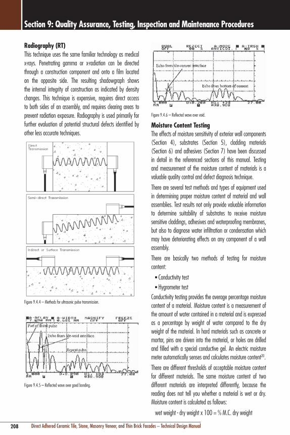
208 Direct Adhered Ceramic Tile, Stone, Masonry Veneer, and Thin Brick Facades – Technical Design Manual
Section 9: Quality Assurance, Testing, Inspection and Maintenance Procedures
Figure 9.4.6 – Reflected wave over void.
Moisture content TestingThe effects of moisture sensitivity of exterior wall components (Section 4), substrates (Section 5), cladding materials (Section 6) and adhesives (Section 7) have been discussed in detail in the referenced sections of this manual. Testing and measurement of the moisture content of materials is a valuable quality control and defect diagnosis technique.
There are several test methods and types of equipment used in determining proper moisture content of material and wall assemblies. Test results not only provide valuable information to determine suitability of substrates to receive moisture sensitive claddings, adhesives and waterproofing membranes, but also to diagnose water infiltration or condensation which may have deteriorating effects on any component of a wall assembly.
There are basically two methods of testing for moisture content:
n Conductivity testn Hygrometer test
Conductivity testing provides the average percentage moisture content of a material. Moisture content is a measurement of the amount of water contained in a material and is expressed as a percentage by weight of water compared to the dry weight of the material. In hard materials such as concrete or mortar, pins are driven into the material, or holes are drilled and filled with a special conductive gel. An electric moisture meter automatically senses and calculates moisture content20.
There are different thresholds of acceptable moisture content for different materials. The same moisture content of two different materials are interpreted differently, because the reading does not tell you whether a material is wet or dry. Moisture content is calculated as follows:
wet weight - dry weight x 100 = % M.C. dry weight
radiography (rT)This technique uses the same familiar technology as medical x-rays. Penetrating gamma or x-radiation can be directed through a construction component and onto a film located on the opposite side. The resulting shadowgraph shows the internal integrity of construction as indicated by density changes. This technique is expensive, requires direct access to both sides of an assembly, and requires clearing areas to prevent radiation exposure. Radiography is used primarily for further evaluation of potential structural defects identified by other less accurate techniques.
Figure 9.4.4 – Methods for ultrasonic pulse transmission.
Figure 9.4.5 – Reflected wave over good bonding.

209Direct Adhered Ceramic Tile, Stone, Masonry Veneer, and Thin Brick Facades – Technical Design Manual
Section 9: Quality Assurance, Testing, Inspection and Maintenance Procedures
Figure 9.4.7 – In-situ Relative Humidity Test Kit.22
There is a direct relationship between the relative humidity of a material and its moisture content; different materials have different safe moisture contents, but a relative humidity reading of 75% RH (which is considered the upper limits of air dry) is a safety moisture content threshold (75% RH in wood = 18% MC, 75% RH in concrete = 10% MC).
A calcium chloride test is another type of hygrometer. This test involves the use of proprietary kits23 to test the amount of moisture (by weight) that can be absorbed by anhydrous calcium chloride over a 24 hour period and are measured in lbs. (of moisture)/1,000 ft2/24 hours. Results of less than 3 lb/1,000 ft2/24 hours are considered acceptable for vapor impermeable floor coverings, moisture sensitive adhesives, waterproofing membranes, and to minimize the occurrence of efflorescence. This test is primarily for testing vapor emission on horizontal floor surfaces under interior, climate controlled conditions; moisture level readings can be misleading because it is difficult to determine the source of moisture in a wet or humid exterior environment even with isolation of the test apparatus. ASTM F1869 "Standard Test Method for Measuring Moisture Vapor Emission Rate of Concrete Subfloor Using Anhydrous Calcium Chloride.”
The simplest qualitative method of moisture testing is the Plastic Sheet Test Method detailed by ASTM D4263 “Standard Test Method for Indicating Moisture In Concrete by the Plastic Sheet Method.” This test involves taping an 18" x 18" (450 x 450 mm) piece of 10 mil (0.05 mm) thick polyethylene plastic sheet to a substrate surface for 16 hours. If condensation or visible dampness appears, the substrate should be allowed to dry for further testing. Testing with this method poses problems similar to moisture content testing with calcium chloride.
A heavy material such as concrete, will have a much lower percentage moisture content than a light material like wood that has the same amount of water in it because, as you can see from the formula, the divisor is a larger number. So a moisture content of 10% for wood is relatively dry, while in concrete 10% is damp. An additional problem with percentage moisture content is that materials moisture content can vary through the cross section, and may not be an indication of steady state of wet or dry, (i.e. materials can be wet on the bottom and dry at the top at the same time). General rules for percentage moisture content are that readings less than 10% in cementitious materials are safe for application of water sensitive claddings, membranes or adhesives.
Hygrometer testing establishes the relative humidity (RH) of a material throughout its depth. In concrete, RH is a property of the air adjacent to liquid water in the concrete pores. Within each pore, the interface between the liquid water and the air forms a meniscus. Because the restraining forces of a meniscus that hold the water molecules in the liquid water are a function of its curvature, the evaporation rate (and thus the local RH) is also a function of the curvature. When water is removed from the concrete pores, either through external drying or through the hydration reaction, larger pores empty first. As progressively smaller pores empty, the menisci curvatures in the remaining pores become more pronounced, and the RH is reduced.21 The equilibrium RH is often measured at 40% depth of the concrete for pours which dry from one side. When RH readings do not exceed 75% RH, a surface is considered safe for application of moisture sensitive materials (e.g. vinyl flooring). There are several methods for measuring relative humidity. The traditional method is to tape 12" x 12" (300 x 300 mm) polyethylene plastic to a surface and place a hygrometer underneath. When the entrapped air reaches moisture equilibrium with the material (usually 24–36 hours), the relative humidity is measured, This method, however, is unreliable for it requires the hygrometer to be left unattended. Fast and reliable methods use electronic equipment with probes which are left within the concrete. Once these probes reach equilibrium, a reusable electronic sensor is inserted into the probe and provides an immediate reading of the RH in that area.
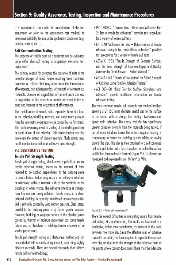
210 Direct Adhered Ceramic Tile, Stone, Masonry Veneer, and Thin Brick Facades – Technical Design Manual
Section 9: Quality Assurance, Testing, Inspection and Maintenance Procedures
n ISO 13007-2 “Ceramic tiles – Grouts and Adhesives Part 2: Test methods for adhesives” provides test procedures for a variety of tensile pull tests
n EN 1348 “Adhesives for tiles – Determination of tensile adhesion strength for cementitious adhesives” provides test procedures for a variety of tensile pull tests
n ASTM C 1583 "Tensile Strength of Concrete Surfaces and the Bond Strength of Concrete Repair and Overlay Materials by Direct Tension – Pull-off Method."
n ASTM D 4541 “Standard Test Method for Pull-off Strength of Coatings Using Portable Adhesion Testers.”
n ACI 503–30 “Field Test for Surface Soundness and Adhesion” provide additional information on tensile adhesion testing.
The most common tensile pull strength test method involves securing a 2" (50 mm) diameter metal disc to the surface to be tested with a strong, fast setting, two-component epoxy resin adhesive. The epoxy typically has significantly greater adhesive strength than the materials being tested. If an adhesive interface below the surface requires testing, it is necessary to isolate the cladding by core drilling or sawing around the disc. The disc is then attached to a self-contained hydraulic pull tester and a force is applied normal to the surface until failure (separation) is induced (Figure 9.5.1). Results are measured and expressed in psi, N/mm2 or MPa.
Figure 9.5.1 – Tensile pull test equipment.25
There are several difficulties in interpreting results from tensile pull testing. First and foremost, the results are best used as a qualitative, rather than quantitative, assessment of the bond between two materials. Since the effective area of adhesive contact is uncertain, the force required to separate the surfaces may give no clue as to the strength of the adhesive bond at the points where contact does occur. There must be adequate
It is important to check with the manufacturer of the test equipment, or refer to the appropriate test method, to determine suitability for use under application conditions (e.g. exterior, vertical, etc…)
Salt contamination TestingThe presence of soluble salts on a substrate can be evaluated using either chemical testing or proprietary electronic test equipment.24
The primary reason for detecting the presence of salts is the potential danger of bond failure resulting from continued depletion of calcium that may occur from the formation of efflorescence, and subsequent loss of strength of cementitious materials. Chloride ion degradation of cement paste can lead to degradation of the concrete or mortar and result in loss of bond and increase in the occurrence of efflorescence.
The crystallization of soluble salts, especially those that form in the adhesive/cladding interface, can exert more pressure than the volumetric expansion forces caused by ice formation. This mechanism may result in spalling of the cladding material or bond failure of the adhesive. Salt contamination can also accelerate the setting of cement mortars. Flash setting may result in reduction or failure of adhesive bond strength.
9.5 DeSTrucTIve TeSTIngTensile Pull Strength TestingTensile pull strength testing, also known as pull-off or uniaxial tensile adhesion testing, measures the amount of force required to be applied perpendicular to the cladding plane to induce failure. Failure may occur at an adhesive interface, or cohesively within a material such as the substrate or the cladding; in other words, the adhesive interface is stronger than the material being adhered. Tensile stress in a direct adhered cladding is typically considered non-consequential, and is primarily caused by wind suction pressure. Shear stress parallel to the cladding plane is by far of greater concern. However, buckling or warpage outside of the cladding plane caused by thermal or moisture movement can cause tensile failure and is, therefore, a valid qualitative measure of in-service performance.
Tensile pull strength testing is a destructive method and can be conducted with a variety of equipment, each using slightly different methods. There are several standards that address tensile pull test methodology;

211Direct Adhered Ceramic Tile, Stone, Masonry Veneer, and Thin Brick Facades – Technical Design Manual
Section 9: Quality Assurance, Testing, Inspection and Maintenance Procedures
In-Situ Shear Bond Strength TestingThe different types of movement presented in Section 4 can cause differential movement parallel to the cladding plane. Shear bond strength testing is a common method used to determine the amount of force required to be applied parallel to the plane of the cladding to induce failure at the adhesive interface. This test is more meaningful than an adhesion or tensile pull strength test because direct adhered cladding installations are exposed primarily to shear stresses. However, as discussed in the preceding section, tensile testing is also important to gauge resistance to out of plane buckling. Unfortunately, shear bond strength testing is cost effective only as a laboratory test using core samples from mock-ups or the actual construction, and not as an “in-situ” or in service test. While equipment for conducting in-situ shear bond tests exists (Figure 9.5.2) difficulty remains in configuring equipment to induce stress parallel to the cladding plane.
Figure 9.5.2 – In-situ shear bond test equipment.27
core DrillingThis procedure involves the use of specially designed electric or hydraulically operated drills with carbide or diamond tipped core drill bits that can extract a core up to 6" (150 mm) in diameter to various depths. Equipment to drill cores up to 24" (600 mm) in diameter are available, but the size and logistics of operating this equipment on a wall other than at ground level is cost prohibitive and does not add value over smaller diameter cores. The purpose of core drilling may be to visually examine the cross section of a wall assembly for any obvious material or construction defects, subject the sample to laboratory testing of compressive or tensile strength, or provide for chemical analysis. Selection of equipment specifically designed for this purpose (Figure 9.5.3) will
sampling in order to qualify the results. Also, results are reported as force per unit area, and should be interpreted as average stress rather than uniform stress across the contact area. Stress distribution is rarely uniform across an adhesive assembly. Results are also greatly influenced by other factors such as core size or alignment of the test equipment to the surface. Test results are also difficult to interpret because there are no uniform standards for tensile adhesive strength of external cladding or of the cohesive strength of plasters or mortars. European norms require minimum tensile pull strength of 0.5 MPa (72.5 psi) for direct adhered cladding, with a voluntary standard of 1 MPa (145 psi) for large format ceramic tile cladding. Brazilian standards require 1 MPa (145 psi) for high performance applications such as facades. Some standards require as high as 1.5 MPa (217.5 psi), or as low as 0.35 MPa (50 psi).
An important note; tensile pull strength results are not to be confused or compared with shear bond strength results commonly provided by manufacturers as a measure of adhesive mortar performance with certain cladding/substrate combinations. While there is no direct correlation between the two tests, studies have indicated that tensile pull strength is approximately 57% of direct shear bond strength.26
One of the benefits of a tensile pull test is that it provides not only a measurement of adhesion strength between materials, but also confirms the quality of the tensile or cohesive strength of the adhered materials, such as the cladding or a cement plaster/render (cohesive qualities of adhered materials could be weaker than the adhesive bond between them). The Portland Cement Association (PCA) has also determined that the tensile strength of concrete is approximately 8 to 12% of its compressive strength. A tensile pull test conducted over 2,000 psi (13.8 MPa) compressive strength adhesive mortar should yield results of 160 psi (1.1 MPa); however, this is only an approximate measure of a cement mortar’s cohesive strength. An example is where a pull test induces failure within the cement plaster/render layer. This is very common when high strength claddings and adhesives mortars are employed, only to be sacrificed by a poor quality plaster/render mix and installation. Similarly, a fragile cladding material such as a “young” slate stone (see Section 6.3 – Slate) will typically fail cohesively along the parallel cleavage plane during a tensile pull test.

212 Direct Adhered Ceramic Tile, Stone, Masonry Veneer, and Thin Brick Facades – Technical Design Manual
Section 9: Quality Assurance, Testing, Inspection and Maintenance Procedures
Most common defects can occur at the interface or within any of the three layers, and evaluation of these areas hidden from direct view and contact is often one of the most difficult aspects of quality assurance for a direct adhered cladding system. Careful analysis of defects is very important, for in many cases, the symptoms manifest in locations other than the point of origin. Cracking and efflorescence are perfect examples, as they typically manifest on the surface of the cladding, yet may originate from poor back-up wall detailing and construction.
Staining and WeatheringStaining and weathering are primarily aesthetic defects, although prolonged exposure to weather and certain types of staining, such as that caused by atmospheric pollution or efflorescence, can lead to functional defects and subsequent deterioration or failure of the cladding materials.
causes of Staining and Weatheringn Water exposure and infiltrationn Solar exposure (UV light)n Corrosion of metal componentsn Biological growthn Atmospheric pollutionn Efflorescence (soluble salt migration)n Fluid (polymer) migration (e.g. adhesives, sealants)
corrosion of Metal componentsA steel wire mesh is often incorporated into cement leveling plasters/renders and attached to the structure or back-up wall construction to isolate poor surface conditions or incompatible substrate materials (see Section 5 – Cement Plasters/ Renders). Smooth concrete surfaces, friable surfaces such as cellular CMU, deteriorated or contaminated surfaces, or substrates which may undergo significant differential movement are examples where wire mesh should be employed. It is important that a corrosion-resistant metal or galvanized coating is used for both the mesh as well as the fasteners. Corrosion of the fastener is the most common mode of failure in wire mesh applications, and can result in staining. Rust staining can also be a symptom of the early stages of failure of structural attachment or the entire wall system.
prevent percussive damage to adjacent areas and minimize damage from binding. In order to minimize difficult to repair destruction to in-service installations caused by this technique, it is recommended that this test method be employed primarily in evaluating test panels constructed in advance of full scale construction.
Figure 9.5.3 – Core drilling equipment.28
9.6 Types, causes and remediation of DefectsDefects in a direct adhered wall system can generally be classified according to type and location. The type of defect can be either aesthetic or functional. Aesthetic defects affect the appearance of a facade, but do not typically affect the safety. Some aesthetic defects, such as efflorescence, can ultimately lead to functional defects if the fundamental cause is not remedied. Functional defects, such as bond failure, affect both appearance and human safety, as well as the integrity and safety of other components of the wall system. Common aesthetic and functional defects are listed below:
common Types of DefectsAesthetic Defects
n Stainingn Efflorescence
Functional Defectsn Crackingn Delamination and bond failuren Movement and grout joint failure
The location of the defect is also critical in evaluation and recommendation of corrective action. A direct adhered wall system consists of three distinct layers:
locations of Defectsn Outer cladding material layern Adhesive layern Substrate and back-up wall construction layer

213Direct Adhered Ceramic Tile, Stone, Masonry Veneer, and Thin Brick Facades – Technical Design Manual
Section 9: Quality Assurance, Testing, Inspection and Maintenance Procedures
common Sources of efflorescence
Principal efflorescing Salt Most Probable Source
Calcium Sulfate (CaSO4) Brick
Sodium Sulfate (Na2SO4) Cement-Brick Reactions
Potassium Sulfate (K2SO4) Cement-Brick Reactions
Calcium Carbonate (CaCO3) Mortar or Concrete Backing
Sodium Carbonate (Na2CO3) Mortar
Potassium Carbonate (K2CO3) Mortar
Sodium Chloride (NaCl) Acid Cleaning
Vanadyl Sulfate (VOSO4) Brick
Vanadyl Chloride (VOCl2) Acid Cleaning
Manganese Oxide (Mn3O4) Brick
Iron Oxide (Fe2O3) Iron In Contact or Brick with Black Core
Iron Hydroxide (Fe(OH)3) Iron In Contact or Brick with Black Core
Calcium Hydroxide (Ca(OH)2) Cement
Figure 9.6.1 – Sources of soluble salts.
efflorescence – Sources of Soluble Saltsn Hydration of cementitious materials (calcium hydroxide)n Calcium chloride contamination – ocean/sea (airborne,
sand)n Deicing salts (sodium chloride, calcium chloride)n Mixing water (calcium sulfate or calcium chloride
softeners)n Cement accelerator or anti-freeze admixtures (calcium
chloride)n Acid etching and cleaning residue (chlorides)n Lime used in mortars (calcium sulfate)
cement Hydration – The most common source is from cementitious materials, such as concrete, cement plasters/renders, concrete masonry units, concrete backer board units, and cement based mortars, including latex cement adhesive mortars. One of the natural by-products from cement hydration (the chemical process of hardening) is calcium hydroxide, which is soluble in water. If cementitious materials are exposed to water for prolonged periods and evaporate slowly, the calcium hydroxide solution evaporates on the surface of the exterior wall, combines with carbon dioxide in the atmosphere (see also Section 5.3 – Carbonation), and forms
efflorescenceEfflorescence is, in effect, a type of staining. Efflorescence is a white crystalline deposit that forms on or near the surface of concrete, masonry, and cement based materials. It is the most common post-installation defect in direct adhered exterior ceramic tile, stone, masonry veneer, and brick wall systems.
Efflorescence can range from a cosmetic annoyance that is easily removed, to a serious problem that could cause adhesive bond failure or require extensive corrective construction and aggressive removal procedures.
Efflorescence starts as a salt which is dissolved by water; the salt solution is then transported by gravity or by capillary action to a surface exposed to air, where the solution evaporates and leaves behind the crystalline deposit. Efflorescence can also occur beneath the surface or within ceramic tile, stone, or thin brick units, and is known as cryptofflorescence.
Occasionally, staining on direct adhered facades is misdiagnosed as efflorescence. Vanadium and molybdenum compounds in ceramic tile, and manganese compounds in thin brick can be dissolved by acid cleaning, often leaving behind an insoluble deposit.
Efflorescence occurs from three simultaneous occurrence of conditions listed below. Theoretically, efflorescence cannot occur if one condition does not exist, it is impracticable to completely eliminate the confluence of these conditions in an exterior wall. However, the conditions that cause efflorescence can be easily controlled and the symptoms minimized, to the point where deposits are not visible, or easily removed and non-recurring.
causes of efflorescencen Presence of soluble saltsn Presence of water (for extended period)n Transporting force (gravity, capillary action, hydrostatic
pressure, evaporation)
Presence of Soluble SaltsThere are numerous sources of soluble salts listed in Figure 9.6.1. There is always the potential for efflorescence when concrete and cement mortars, adhesives and grouts are exposed to the weather. Other sources of soluble salts can be monitored, controlled or completely eliminated.

214 Direct Adhered Ceramic Tile, Stone, Masonry Veneer, and Thin Brick Facades – Technical Design Manual
Section 9: Quality Assurance, Testing, Inspection and Maintenance Procedures
screen walls) to control or prevent water penetration. Each type of wall is designed to minimize efflorescence either by providing barriers to water penetration, minimize water contact with potential contaminants, or controlling the flow of water that contacts contaminated materials.
Section 3 and 4 presented the proper architectural detailing and information necessary to prevent water infiltration. Waterproofing and flashing at roof/wall intersections, parapets, window sills and heads, spandrels, movement joints, and perimeter interfaces with other components of the facade wall assembly is the primary solution or remedy to prevent efflorescence.
Sealers and coatingsWater repellent coatings are commonly specified as a temporary and somewhat ineffective solution to fundamentally poor wall design and/or construction. In some cases, water repellents may actually contribute to, rather than prevent the formation of efflorescence. Water repellents cannot stop water from penetrating the hairline cracks in the surface of cladding, or from penetrating through improperly designed or constructed joints and openings. Water repellents also do not prevent water infiltration caused by poor wall design or construction. As the infiltrated water travels to the surface by capillary action to evaporate, it is stopped by the repellent, where it then evaporates through the coating (most sealers have some vapor permeability) and leaves behind the soluble salts to crystallize just below the surface of the cladding. The collection of efflorescence under the water repellent coating may cause spalling of the cladding material, or may result in gross accumulation of efflorescence (see Section 9.3 Protection and Sealing).
effects of efflorescenceThe initial occurrence of efflorescence is primarily considered an aesthetic defect. However, if the fundamental cause (typically water infiltration) is left uncorrected, continued efflorescence can become a functional defect and affect the integrity and safety of a direct adhered facade.
The primary danger is potential bond failure resulting from continued depletion of calcium and subsequent loss of strength of cementitious adhesives and underlying cementitious components. The crystallization of soluble salts, especially
calcium carbonate, one of many forms of efflorescence. Once the calcium hydroxide is transformed to calcium carbonate efflorescence, it is not soluble in water, making removal difficult.
calcium chloride contamination – A common source of soluble salts is either direct or airborne salt water contamination of mixing sand, back-up wall materials and surface of the substrate. Mixing water can also be contaminated with high levels of soluble salts. Figure 9.6.2 shows the analysis of water samples from 6 different city water supplies as compared to seawater. Typically, water with less than 2,000 ppm of total dissolved solids will not have any significant effect on the hydration of portland cement, although lower concentrations can still cause some efflorescence.
Acid etching – (see Section 5.4 – Acid Etching and Section 9 – Removal of Efflorescence).
lime in Mortars – Non-hydrated lime, used in leveling mortars/renders, contains calcium sulfate, which is a soluble salt. Uncontrolled water penetration through unprotected openings, cracks or incorrectly constructed joints may allow sufficient saturation of lime mortars to dissolve these salts in large quantities. The benefit of the autogenous or “self-healing” qualities of lime mortars has long been the subject of debate in the masonry industry. The very chemical reaction which can seal hairline cracks in lime mortars can also cause efflorescence.
Presence of WaterWhile you cannot control naturally occurring soluble salts in portland cement based materials, the proper design, construction and maintenance of an exterior wall system can control and minimize wall components from both water penetration and subsequent efflorescence. Without sufficient quantities and periods of exposure to water, salts do not have adequate time to dissolve and precipitate to the surface of a facade, and efflorescence simply cannot occur.
Rain and snow are the principal sources of water. Water which condenses within wall cavities or components is an often overlooked source of water.
Section 2 presented several wall construction types that may be employed (e.g. barrier, cavity, and pressure equalized rain

215Direct Adhered Ceramic Tile, Stone, Masonry Veneer, and Thin Brick Facades – Technical Design Manual
Section 9: Quality Assurance, Testing, Inspection and Maintenance Procedures
Fluid migration, also known as “latex migration”, refers to staining caused by water soluble latex additives. It is recommended to verify that a manufacturer’s polymer formulation for a liquid latex additive or a dry dispersive polymer powder is not water soluble. Similarly, all installations of external cladding which use latex cement adhesive mortars must be protected from significant rain exposure during the initial setting period (typically 24 – 48 hours) during which polymers may be subject to fluid migration or leaching (see Section 7 – Weather Protection – Wet Conditions). Fluid migration staining can manifest as follows:
Darkening of the cladding Material – The plasticizers of certain sealants or polymers can be absorbed by porous cladding materials like stone or bricks. Permanent darkening of the edges of the cladding in contact with the sealant may occur.
Waterproofing of the cladding – Hydrophobic action (non water absorptive) adjacent to sealant joints may be caused by sealant fluid migration. The cladding area near the joints will remain dry, and the central areas will absorb moisture, leading to a darkening of the cladding surface in areas away from the sealant joints. This phenomenon is dependent on the absorption of the cladding material, and is typical of more porous stone and applications which use improperly specified fluid flexible sealants to fill all the joints between the cladding pieces or tiles. Typically this condition is not permanent, but can be minimized or prevented with the use of a suitable primer (e.g. LATICRETE® 9118 Primer) designed for this purpose.
Dirt Pick-up on the cladding – Adjacent to sealant joints where fluid has been absorbed by porous cladding material. Dirt pick-up is another common problem and is a function of type of exposure, surface hardness, type of and length of cure, and the formulation; but not the sealant polymer type.
rundown of the Fluid – Fluid components can accumulate on horizontal edges and replicate normal dirt runoff patterns or be improperly diagnosed as efflorescence.
those that form in the adhesive-cladding interface, or within the cladding material (see Sealers and Coatings, this section), can exert more pressure than the volume expansive forces caused by ice formation. This mechanism may also result in spalling or bond failure.
TyPIcAl AnAlySIS OF cITy WATer SuPPlIeS AnD SeAWATer
Parts Per Million
Analysis # 1 2 3 4 5 6 Seawater*
Silica (SiO2) 2.4 0.0 6.5 9.4 22.0 3.0 0.0
Iron (Fe) 0.1 0.0 0.0 0.2 0.1 0.0 0.0
Calcium (Ca) 5.8 15.3 29.5 96.0 3.0 1.3 50 – 480
Magnesium (Mg)
1.4 5.5 7.8 27.0 2.4 0.3 260 – 1,410
Sodium (Na) 1.7 16.1 2.3 183.0 215.0 1.4 2,190 – 12,200
Potassium (K)
0.7 0.0 1.6 18.0 9.8 0.2 70 – 550
Bicarbonate (HCO3)
14.0 35.8 122.0 334.0 549.0 4.1 0.0
Sulfate (SO4)
9.7 59.9 5.3 121.0 11.0 2.6 580 – 2,810
Chloride (Cl) 2.0 3.0 1.4 280.0 22.0 1.0 3,960 – 20,000
Nitrate (NO3) 0.5 0.0 1.6 0.2 0.5 0.0 0.0
Total dissolved solids
31.0 250.0 125.0 983.0 564.0 19.0 35000.0
* Different seas contain different amounts of dissolved salts
Figure 9.6.2 – Analysis of city water and seawater samples for soluble salt levels.
Fluid MigrationFluid migration from sealant joint materials is a common source of staining in direct adhered facades. This defect most often occurs with certain types of silicone sealants, but can also be caused by some types of soluble polymers found in polymer mortar additives.
This problem is more a function of a manufacturer’s formulation than polymer type (see Section 4 – Movement Joints – Compatibility). There is no correlation with a particular polymer type (i.e., silicone vs. polyurethane), because the problem is typically caused by plasticizing additives and not the polymers. However, fluid streaking depends on both formulation and sealant polymer type. There are several silicones on the market, (such as Dow Corning® 756 Silicone Sealant HP) which have specifically addressed and overcome the above aesthetic problems associated with sealants used as both movement joints and fillers between pieces of cladding.
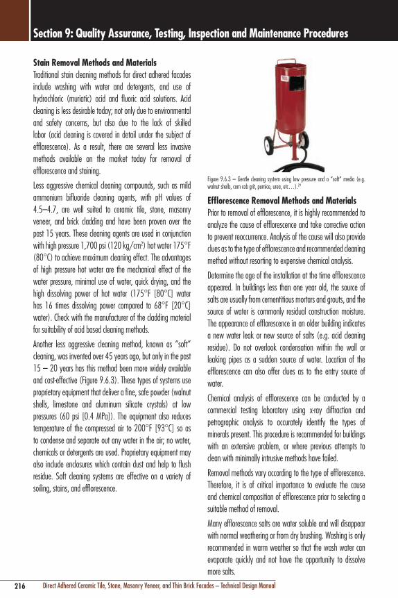
216 Direct Adhered Ceramic Tile, Stone, Masonry Veneer, and Thin Brick Facades – Technical Design Manual
Section 9: Quality Assurance, Testing, Inspection and Maintenance Procedures
Figure 9.6.3 – Gentle cleaning system using low pressure and a “soft” media (e.g. walnut shells, corn cob grit, pumice, urea, etc…).29
efflorescence removal Methods and MaterialsPrior to removal of efflorescence, it is highly recommended to analyze the cause of efflorescence and take corrective action to prevent reoccurrence. Analysis of the cause will also provide clues as to the type of efflorescence and recommended cleaning method without resorting to expensive chemical analysis.
Determine the age of the installation at the time efflorescence appeared. In buildings less than one year old, the source of salts are usually from cementitious mortars and grouts, and the source of water is commonly residual construction moisture. The appearance of efflorescence in an older building indicates a new water leak or new source of salts (e.g. acid cleaning residue). Do not overlook condensation within the wall or leaking pipes as a sudden source of water. Location of the efflorescence can also offer clues as to the entry source of water.
Chemical analysis of efflorescence can be conducted by a commercial testing laboratory using x-ray diffraction and petrographic analysis to accurately identify the types of minerals present. This procedure is recommended for buildings with an extensive problem, or where previous attempts to clean with minimally intrusive methods have failed.
Removal methods vary according to the type of efflorescence. Therefore, it is of critical importance to evaluate the cause and chemical composition of efflorescence prior to selecting a suitable method of removal.
Many efflorescence salts are water soluble and will disappear with normal weathering or from dry brushing. Washing is only recommended in warm weather so that the wash water can evaporate quickly and not have the opportunity to dissolve more salts.
Stain removal Methods and MaterialsTraditional stain cleaning methods for direct adhered facades include washing with water and detergents, and use of hydrochloric (muriatic) acid and fluoric acid solutions. Acid cleaning is less desirable today; not only due to environmental and safety concerns, but also due to the lack of skilled labor (acid cleaning is covered in detail under the subject of efflorescence). As a result, there are several less invasive methods available on the market today for removal of efflorescence and staining.
Less aggressive chemical cleaning compounds, such as mild ammonium bifluoride cleaning agents, with pH values of 4.5–4.7, are well suited to ceramic tile, stone, masonry veneer, and brick cladding and have been proven over the past 15 years. These cleaning agents are used in conjunction with high pressure 1,700 psi (120 kg/cm2) hot water 175°F (80°C) to achieve maximum cleaning effect. The advantages of high pressure hot water are the mechanical effect of the water pressure, minimal use of water, quick drying, and the high dissolving power of hot water (175°F [80°C] water has 16 times dissolving power compared to 68°F [20°C] water). Check with the manufacturer of the cladding material for suitability of acid based cleaning methods.
Another less aggressive cleaning method, known as “soft” cleaning, was invented over 45 years ago, but only in the past 15 – 20 years has this method been more widely available and cost-effective (Figure 9.6.3). These types of systems use proprietary equipment that deliver a fine, safe powder (walnut shells, limestone and aluminum silicate crystals) at low pressures (60 psi [0.4 MPa]). The equipment also reduces temperature of the compressed air to 200°F [93°C] so as to condense and separate out any water in the air; no water, chemicals or detergents are used. Proprietary equipment may also include enclosures which contain dust and help to flush residue. Soft cleaning systems are effective on a variety of soiling, stains, and efflorescence.

217Direct Adhered Ceramic Tile, Stone, Masonry Veneer, and Thin Brick Facades – Technical Design Manual
Section 9: Quality Assurance, Testing, Inspection and Maintenance Procedures
adjacent areas) with water to prevent acid residue from absorbing below the surface. While most acids quickly lose strength upon contact with a cementitious material and do not dissolve cement below the surface, saturating the surface is more important to prevent absorption of soluble salt residue (potassium chloride) which cannot be surface neutralized and rinsed with water. As stated previously, this condition can be a source of soluble salts and allow recurrence of the efflorescence problem intended to be corrected by the acid cleaning.
Application of acid solutions should be made to small areas (<10 ft2 [1 m2]) and left to dwell for no more than 5 minutes before brushing with a stiff acid resistant brush and immediately rinsing with water. Acid solutions can also be neutralized with a 10% solution of ammonia or potassium hydroxide.
Functional Defects crackingCracking is a broad term applied to the distinct separation of a material across its cross section. Cracks may be structural and affect the safety of a building facade, or may disfigure the appearance of a building and allow wind driven rain, dirt and air to penetrate. In a direct adhered wall assembly, cracking may occur in the cladding material, in the rigid joint filler material (grout), or in any one of the underlying wall components hidden from view. In many cases, cracks develop in one component of the wall assembly, but are transmitted by composite action of the adhered assembly to other components.
Identifying Types and causes of crackingWhile the mechanisms that cause cracking are quite complex, for purposes of this manual, types of cracking in a direct adhered facade can be categorized according to the cause of cracking as follows:
n Structural cracksn Surface cracks
Structural cracking results from fundamental defects in design or construction, or from corrosion of underlying structural concrete reinforcing bars or leveling mortar wire mesh reinforcement. Structural cracking is typically difficult and costly to remedy. These types of cracks are typically wide (up to 1/8" [3 mm]), are not localized at one particular tile or piece of cladding, and usually coincide with structural components or interfaces with adjacent or underlying materials/components of the wall assembly.
Efflorescence that cannot be removed with water and scrubbing requires chemical removal. Using muriatic acid is a conventional cleaning method for stubborn efflorescence, however, even with careful preparation, cladding and grout joints can get etched and damaged (see Section 5 – Acid Etching). There are less aggressive alternatives to muriatic acid; several are described in the previous section on stain removal; another method is using a less aggressive sulfamic acid, available in powdered form. This acid dissolved in water between a 5–10% concentration should be strong enough to remove stubborn efflorescence without damage to the cladding or grout joint materials. There are also proprietary, non-acid based chemical cleaners which have some success with minor efflorescence problems.
Regardless of the cleaning method selected, the cleaning agent should not contribute additional soluble salts. For example, acid cleaning can deposit potassium chloride residue (a soluble salt) if not applied, neutralized and rinsed properly, thus potentially exacerbating the condition which it was employed to remove.
Calcium carbonate efflorescence is a type of efflorescence where the calcium salts combine with carbon dioxide in the air and form a hard, crusty deposit which is insoluble in water. However, long term exposure to air and rain water will gradually transform this residue to calcium hydrogen carbonate, which is soluble in water. So long term weathering can eliminate this type of efflorescence. Unfortunately, if the condition is not acceptable in the short term, and water or mild chemical cleaning proves ineffective, it may be necessary to wash the surface with a dilute solution (5–10%) of hydrochloric (muriatic) acid. Aqueous solutions of acids are commercially available for ease of handling and prevention of dilution errors. For integrally pigmented grouts, a 2% maximum acid solution is recommended, otherwise, surface etching can reveal aggregate and wash away color at the surface.
Acids should not be used on glazed tile or polished stone, for the acid solution can etch and dull the glaze or polished surface, or react with compounds in the glaze and redeposit brown stains on the cladding which are insoluble and impossible to remove without ruining the tile.
Before applying any acid solution, always test a small, inconspicuous area to determine any adverse effect. Just prior to application, saturate the surface to be cleaned (and

218 Direct Adhered Ceramic Tile, Stone, Masonry Veneer, and Thin Brick Facades – Technical Design Manual
Section 9: Quality Assurance, Testing, Inspection and Maintenance Procedures
can be caused by unintended impact with foreign objects, defective cladding or underlying substrate material, defective installation, or from normal weathering and deterioration such as freeze-thaw cycling over a period of years. Surface cracking can also be a minor manifestation of structural movement, such as expansion or shrinkage.
Surface cracking can usually be repaired by simple replacement of the cladding material. In many cases, surface cracking, especially in filler (grout) joint material, poses no safety risk (this should be verified by testing), and the cladding may be left in place and behavior of the cracking monitored. While benign cracking may not be a safety risk, it does present other problems such as water infiltration. Water infiltration could lead to subsurface efflorescence or spalling, which ultimately may pose a safety risk. So neglect of benign surface cracking must be weighed against the risks under certain conditions.
Delamination and Bond FailureDelamination and bond failure are, in effect, synonymous terms. Technically, there are subtle differences, but for the purposes of this manual, these terms both mean that either the cladding material/adhesive interface, or one of the underlying substrate or back-up wall interfaces has physically separated.
This defect is the number one concern and fear of owners, architects, building officials, and construction contractors when considering a direct adhered ceramic tile, stone, masonry veneer, or thin brick clad facade. The result of delamination or bond failure is typically pieces or sections of cladding or other components of the wall which fall off and pose a serious risk to public safety. There is always a risk of fall-off from any type of external wall cladding material or system, including those that employ mechanical anchors or load bearing connections. In fact, failures of mechanically anchored external cladding systems are more prominent and catastrophic than direct adhered cladding systems.32 The only difference is that the incidence rate is typically greater for a newer technology which requires time to accumulate empirical experience and develop a broad base of knowledge at all levels.
Delamination and bond failure can be categorized as either adhesive or cohesive. Adhesive bond failure occurs at the adhesive interface between materials such as between the cladding material and the substrate. Cohesive failure is a
In most cases, the cause of structural cracking can be identified by first analyzing the mechanisms of different types of structural movement (see Section 4). Each type of structural movement manifests in typical locations.
Types of structural movement are also associated with typical physical characteristics of cracking. For example, a diagonal crack originating at a corner of a window head and radiating or stepping through joints diagonally (re-entrant crack) would most likely be caused by lack of vertical movement joints to control shrinkage or creep, by deflection or by structural inadequacy of the window lintel that supports the underlying wall at the window opening.
Physical characteristics of Structural cracksn Geometry – vertical, horizontal, diagonal, stepped through
joints, radiatingn Orientation – straight, multi-directionaln Position – origin, terminationn Size – length, width
Remedies for structural cracking focus first on repair of the fundamental structural cause of the cracking, and then repair of the cracks. For example, removal and replacement of cracked tiles caused by lack of movement joints will not prevent recurrence of cracking.
In some cases, localized structural cracking can be repaired without major reconstruction if the cracking was caused by unusual movement. An example could be a wind or seismic event that exceeded the design loads for the structure. The probability of reoccurrence is low, so repairs to cracking of underlying structural elements could be made with epoxy injection techniques, and the cladding could be locally replaced.
Conversely, other situations that cause structural cracking, such as an improperly designed or constructed back-up wall, may not be remedied unless the entire wall is reconstructed. Compromise solutions will either destroy the integrity of the design (for example, installing metal anchors to secure the face of the cladding), or risk public safety.
Surface cracking (Hairline)Surface cracking is typically localized cracking that only occurs on the surface of the cladding material or the filler joint (grout) material and is non-structural in origin. Surface cracking
219Direct Adhered Ceramic Tile, Stone, Masonry Veneer, and Thin Brick Facades – Technical Design Manual
Section 9: Quality Assurance, Testing, Inspection and Maintenance Procedures
typically have dovetail grooves at the back which provide a good mechanical locking effect with traditional cement mortars or lower strength latex cement adhesive mortars. However, high performance adhesives are still recommended, because of the potential for failure at the adhesive substrate interface unless a mechanical locking mechanism is provided on the substrate surface. Examples of a mechanical locking mechanism on the substrate include a ribbed skim coat or spritz/dash/spatter coat using the same high performance adhesive additives together with cement mortar.
Failure at the cladding/adhesive interface can also result from either dust/contamination of the back surface of the cladding, from improper coverage/contact with the back of the cladding, or improper bedding into the adhesive. Most industry standards for exterior wall cladding require a minimum 95% adhesive coverage (ANSI A108.5 2.5.4) and back-buttering of the cladding surface using the thin-bed method. However, these requirements are difficult to achieve on installations which do not employ proper equipment and quality assurance programs during the progress of installation.
Failure at the Adhesive Bedding Mortar/Backup Wall Substrate Interface – The backup wall substrate is often not prepared well enough for a good bond to be formed with the adhesive bedding mortar. This type of failure is more common on dense, smooth substrates with low or no water absorption, such as concrete. Very often dirt, grease, form release agent, and/or curing compounds are responsible for poor bond to concrete where steel or other smooth forms are used.
Sometimes the backup wall substrate is treated to improve the bond between the substrate and the adhesive mortar. A skim/parge coat, or slurry/slush coats (i.e. cement/ sand slurries with or without latex additives), are sometimes applied to the substrate to improve the bond. Skim and bond coats should be applied properly, allowed to dry and should either employ a latex additive or be cured to achieve adequate hardness and bond strength. Keep in mind that the application of a skim/parge/slurry coat does not overcome the need to properly prepare the surface to which they will be applied.
structural failure within a homogeneous material itself, such as a concrete wall surface or a cement render/plaster which separates internally.
Bond failure is most commonly caused by defective design or installation, and is rarely caused by defective cladding or installation products. Prevention relies on implementation and enforcement of a comprehensive quality assurance program for both design and installation (see Section 9.1 – Quality Control and Assurance). A systematic preventative maintenance program provides an added factor of safety to check any oversights of the quality assurance program and prevent catastrophic bond failure.
common causes – Adhesive Bond Failuren Contaminated cladding surfacesn Contaminated substrate surfacesn Partial adhesive coverage and failure to back-butter
claddingn Improper setting (bedding) pressuren Improper mixing/application of adhesiven Improper specification of adhesiven Use of improper adhesiven Differential movement shear and tensile force (expansion,
shrinkage)
Proper methods and materials to prevent the above defects are described in Section 4 – Structural and Architectural Considerations, Section 5 – Substrate Preparation, Section 6 Cladding Selection, and Section 7 – Cladding Installation Materials and Methods. The following information provides a logical sequence of evaluating the cause of bond failure.
Delamination and Adhesive Bond Failure evaluation by location within composite cladding SystemFailure at the Interface Between cladding and Adhesive – This type of failure can occur with cladding types which have smooth backs and which offer little mechanical key between mortar and tile. Glass and pressed porcelain (vitrified) ceramic tile can fail in this way, because they have very low or no absorption. High strength adhesives that rely primarily on pure adhesive strength rather than mechanical locking strength are recommended. This type of failure is rare with the extruded ceramic split-tiles, masonry veneers or thin bricks since they

220 Direct Adhered Ceramic Tile, Stone, Masonry Veneer, and Thin Brick Facades – Technical Design Manual
Section 9: Quality Assurance, Testing, Inspection and Maintenance Procedures
corrective Action for DelaminationIn most cases, the only remedy to delamination is removal and re-installation of the defective cladding system or components of the cladding system. However, epoxy injection techniques can be employed under certain conditions.
Epoxy injection may be used if the delamination or void is thin and restricted enough so that adequate sealing of the delamination area is feasible in order to allow pressure build-up for proper delivery, distribution and performance of the epoxy. There also must be adequate access to the delamination to allow multiple “ports” or points of injection.
Epoxy injection products are typically low viscosity materials used for structural repair of extremely fine hairline cracks. For larger volume repairs on vertical façade cladding, special higher viscosity epoxy gel formulations are necessary.
Other Mechanisms of Adhesion FailureAdhesion failure is usually a result of a combination and confluence of indeterminate factors and rarely caused by a single mechanism. Variations in moisture content, variations in temperature, the creep of a concrete structure, the use of unsuitable or poor quality materials, and poor workmanship may all be contributing factors. Identification of the origin or fundamental cause of failure is often difficult because stresses may occur in any component of the cladding system, but adhesive failure normally occurs along the weakest planes. For example, a ceramic tile back which has not been cleaned may result in reduced adhesive bond, but the lack of movement joints may be the actual mechanism that induces stress beyond the reduced adhesive capability of the contaminated tile back. It is typically indeterminate whether the dirty tile would have failed if movement joints were constructed properly, or if the lack of movement joints would have caused the failure even if the tile were cleaned and installed properly.
The following dimensional movements previously described in Section 4 are usually involved and they can all act together or in opposition to cause a failure:
Moisture expansion of TilesReversible expansion and contraction due to wetting and drying of tiles are relatively small and can, for all practical purposes, be disregarded in this context, except perhaps where large areas are involved with no suitable allowance for movement.
Failure at the cement leveling Plaster/render and Adhesive Interface – In concrete or concrete masonry unit barrier backup wall construction, the backup wall is often leveled/rendered with cement plaster (scratch and brown coats) before the adhesive mortar is applied; this is done at different time intervals before cladding installation is commenced. Failure at the plaster/adhesive mortar interface is not uncommon. There are numerous reasons for failure; poor plaster material or poor preparation and installation methods. The plaster/render should be of good quality (e.g. LATICRETE® 3701 Fortified Mortar Bed) and be installed over a hardened rough texture bond coat (scratch, spritz, dash or spatter dash coat), or, over a hardened rough texture flat skim coat to provide a mechanical key for the adhesive mortar.
Backup wall substrates are often plastered or rendered to provide the correct level and to provide a smooth and even surface for the cladding installation. Failure between the backup wall substrate and plaster is not considered a cladding failure but it leads to failure of cladding and should be considered. Failure of this type can be due to one factor or a combination of numerous factors. Thick layers of cement plaster/render to correct excessive plumb and level tolerance (e.g. bad workmanship) are not uncommon, and are responsible for many failures. A single coat of cement plaster/render should not be thicker than 1/2" (12 mm). If a thick layer of leveling mortar is required to level off an uneven surface, the cement plaster/render should be applied in successive coats. Each coat should be cured, scratched and prepared to receive the next coat.
Metal lath or steel wire mesh is often incorporated into vertical applications of cement leveling plasters/renders and attached to the structure or back-up wall construction to isolate poor surface conditions or incompatible substrate materials (see Section 5 – Cement Plasters/Renders). Smooth concrete surfaces, friable surfaces such as cellular CMU, deteriorated or contaminated surfaces, or substrates which may undergo significant differential movement are examples where wire mesh should be employed. It is important that a corrosion-resistant metal or galvanized coating is used for both the mesh as well as the fasteners. Corrosion of the fastener is the most common mode of failure in wire mesh applications, and can result in failure of any of the cladding components or the entire wall system.

221Direct Adhered Ceramic Tile, Stone, Masonry Veneer, and Thin Brick Facades – Technical Design Manual
Section 9: Quality Assurance, Testing, Inspection and Maintenance Procedures
compressive stresses in adhesive mortars and cladding and are very often a contributing factor towards failure of direct adhered cladding. Bulging or tenting of the cladding material from the substrate is a common symptom of differential movement.
efflorescence or cryptoflorescenceThe primary danger associated with severe efflorescence or cryptoflorescence (the occurrence of efflorescence which is out of view) is the potential adhesive bond failure resulting from the continued depletion of calcium and subsequent loss of strength of cementitious adhesives and underlying cementitious components.
The crystallization of soluble salts, especially those that form in the adhesive/cladding interface, or within the cladding material (see sealers and coatings, this section) can exacerbate calcium depletion by exerting expansive stress. The formation of salt crystals can exert more pressure than the volumetric expansive forces caused by ice formation. This mechanism may result in spalling of the cladding material or adhesive bond failure.
expansion of cementitious Materials Due to Sulfate AttackReaction between sulfates and aluminates in portland cements can occur in wet environments. This reaction is accompanied by large volume increases which can lead to the disruption of concrete, cement plaster and adhesive mortars which can cause adhesion failure at any cementitious interface within the cladding system.
Sealant and grout Joint FailureSealants are widely misused and are a common source and cause of defects in direct adhered facades, especially at movement/expansion joints. Sealants are a critical bridge at perimeter interfaces between cladding and other wall components, and at cladding or movement joints, yet they are routinely designed, specified, and installed improperly.
It is essential to understand that sealants cannot be relied upon to provide the only means of protection against water and air infiltration, especially in barrier walls where the sealant joint may be the only line of defense. Even with proper back-up protection, compliance with installation guidelines is required to ensure proper elongation and compression without peeling or loss of adhesion (see Section 4 – Movement Joints).
The irreversible expansion of ceramic tiles and clay products, referred to as moisture expansion, can be relatively large. This expansion begins the moment the materials leave the kiln. It is a rather slow process and takes place over a long period. Tiles with low moisture expansion, not more than about 0.03%, should be used. Tiles have been removed from buildings where failure had occurred and the moisture expansion of some of these tiles was as high as 7%. Vitrified or, better still, fully vitrified tiles have a low moisture expansion and should not fail as a result of moisture expansion.
Thermal expansion of TilesThe thermal expansion of porcelain (vitrified) tile is relatively small, but when large surfaces are exposed to large temperature differences, significant total movement and differential dimensional movement can occur, leading to stress. The thermal expansion of glass tiles can be slightly or significantly (depending on the glass) higher than that of ceramic tile.
Shrinkage of cement MortarsAdhesive mortars and cement plasters/renders usually shrink more than the backup wall construction. To avoid and to minimize stresses set up due to the shrinkage of mortars, it is necessary to use mortars which have a low drying shrinkage. This can be achieved by using a proprietary, pre-mixed and bagged mortar powders, both for cement plasters/renders (e.g. LATICRETE 3701 Fortified Mortar Bed) and adhesive mortars (e.g. LATICRETE 254 Platinum). If site mixed mortars are specified, use clean, well-graded sand and quality cement mixed to a sand:cement ratio which is appropriate to the type of application. Fine sands which contain a high percentage of clay produce mortars with a high drying shrinkage. Mortars which are rich in cement also have a high drying shrinkage, as do mortars mixed with excess water or latex additive. Mortars with high drying shrinkage typically exhibit large dimensional changes during cycles of wetting and drying.
Differential Movements between Structure and claddingStructures, particularly poured concrete structures, creep from the weight (dead load) of concrete, and from imposed live loads, causing shortening or shrinkage of columns and walls and deflection of beams (see Section 4 Types of Structural Movement). Differential movement in structures can induce

222 Direct Adhered Ceramic Tile, Stone, Masonry Veneer, and Thin Brick Facades – Technical Design Manual
Section 9: Quality Assurance, Testing, Inspection and Maintenance Procedures
Excessive cracking, deterioration, or fallout of grout material is commonly caused by a combination of several factors:
n Excessive movementn Partial filling of narrow or deep jointsn Improper installation practicesn Poor quality grout or improper mix design
Grout cracking from excessive movement is primarily a design consideration, and is prevented by following good architectural and structural design practices (see Section 4). Partial filling is prevented by proper joint width to depth ratio, and making sure that proper tools and installation practices are used. Accepted installation practices, including protection against hot, dry conditions, and types of grout mix designs to prevent defects are described in Section 7.5.
9.7 THe IMPOrTAnce OF SHeAr BOnD STrengTH cHArAcTerISTIcS OF POlyMer-MODIFIeD ceMenT ADHeSIveSThe Importance of Shear Bond Strength characteristics of Polymer-modified cement AdhesivesBy Richard P. Goldberg Architect AIA, CSI/Professional Consultants, Inc./Avon, CT USA
AbstractWith the development of a new generation of polymer-modified cement adhesives, there has been an increasing emphasis on the importance of flexibility and deformation capabilities of these adhesives. While this characteristic has been one of the key elements in the successful application of this type of construction adhesive, the recent international standards initiative to qualify polymer modified cement adhesives primarily by deformation characteristics has failed to consider the equally important balancing characteristic of high shear bond strength and shear modulus*
This research paper utilizes proven adhesive technology theory and quantitative engineering analysis to illustrate the importance of high shear modulus polymer-modified cement adhesives, especially when used for direct adhesion of porcelain tile and natural stone in high performance applications such as exterior building facades. Engineering analysis will illustrate the following mechanisms and attributes:
Failure of sealant joints, while posing no direct safety risk, will allow water, air, and dirt to infiltrate behind the cladding material. Water infiltration presents several problems in non-cavity wall type systems: 1) potential freeze-thaw problems when voids are present, 2) reduction of adhesive strength from long term water saturation, and 3) increased probability of efflorescence and staining. A preventative maintenance program should include periodic visual inspection of sealant joints for deterioration, loss of adhesion/peeling, or other defects described in Section 4. Failure (or impending failure) of sealant joints, as indicated by extreme compression or elongation, is a signal of excessive stress within the cladding system and the potential danger of cracking or adhesive bond failure.
Joints between cladding which are filled with relatively rigid cementitious grout are often provide some stress relief of thermal and moisture movement within the cladding. As a result, traditional cement grout, and even more flexible latex cement grout joints typically develop some very fine hairline cracking or edge separation from the cladding material over a period of time. This condition is considered normal (analogous to checking in wood) and does not have any significant effect on the performance of the cladding system. This is because the primary purpose of grout joints are to separate and fill the joints rather than to hold the cladding together (see Section 7.5 – Purpose of Grout or Sealant Joints). Hairline cracking is best minimized by the use of joint materials such as latex portland cement/sand mixes which provide enough resilience relative to a more brittle material such as plain cement-sand mixtures to absorb compressive stress from expansion without crushing, and absorb tensile stresses at the cladding edges from contraction.
In most countries, standards and regulations require a minimum grout joint width of 1/4" (6 mm) for joints between external cladding to allow the pieces of cladding to move as single or isolated units, rather than monolithic units. Further isolation of movement is handled by separating sections of cladding with movement joints (see Section 4 – Movement Joints). This ensures that the grout or sealant joint should fail first by relieving unusual compressive stress from expansion before it can overstress the cladding or adhesive interface. The dissipation of stress provides an additional safety factor against dangerous delamination or bond failure.
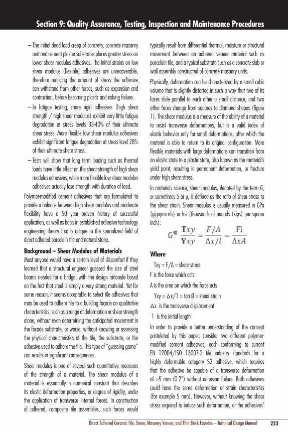
223Direct Adhered Ceramic Tile, Stone, Masonry Veneer, and Thin Brick Facades – Technical Design Manual
Section 9: Quality Assurance, Testing, Inspection and Maintenance Procedures
typically result from differential thermal, moisture or structural movement between an adhered veneer material such as porcelain tile, and a typical substrate such as a concrete slab or wall assembly constructed of concrete masonry units.
Physically, deformation can be characterized by a small cubic volume that is slightly distorted in such a way that two of its faces slide parallel to each other a small distance, and two other faces change from squares to diamond shapes (figure 1). The shear modulus is a measure of the ability of a material to resist transverse deformations, but is a valid index of elastic behavior only for small deformations, after which the material is able to return to its original configuration. More flexible materials with large deformations can transition from an elastic state to a plastic state, also known as the material’s yield point, resulting in permanent deformation, or fracture under high shear stress.
In materials science, shear modulus, denoted by the term G, or sometimes S or μ, is defined as the ratio of shear stress to the shear strain. Shear modulus is usually measured in GPa (gigapascals) or ksi (thousands of pounds (kips) per square inch):
Where
Txy = F/A = shear stress
F is the force which acts
A is the area on which the force acts
Yxy = ∆x/1 = tan Ø = shear strain
∆x is the transverse displacement
1 is the initial length
In order to provide a better understanding of the concept postulated by this paper, consider two different polymer-modified cement adhesives, each conforming to current EN 12004/ISO 13007-2 tile industry standards for a highly deformable category S2 adhesive, which requires that the adhesive be capable of a transverse deformation of >5 mm (0.2") without adhesion failure. Both adhesives could have the same deformation or strain characteristics (for example 5 mm). However, without knowing the shear stress required to induce such deformation, or the adhesives’
– The initial dead load creep of concrete, concrete masonry unit and cement plaster substrates places greater stress on lower shear modulus adhesives. The initial strains on low shear modulus (flexible) adhesives are unrecoverable, therefore reducing the amount of stress the adhesive can withstand from other forces, such as expansion and contraction, before becoming plastic and risking failure.
– In fatigue testing, more rigid adhesives (high shear strength / high shear modulus) exhibit very little fatigue degradation at stress levels 33-40% of their ultimate shear stress. More flexible low shear modulus adhesives exhibit significant fatigue degradation at stress level 28% of their ultimate shear stress.
– Tests will show that long term loading such as thermal loads have little effect on the shear strength of high shear modulus adhesives, while more flexible low shear modulus adhesives actually lose strength with duration of load.
Polymer-modified cement adhesives that are formulated to provide a balance between high shear modulus and moderate flexibility have a 50 year proven history of successful application, as well as basis in established adhesive technology engineering theory that is unique to the specialized field of direct adhered porcelain tile and natural stone.
Background – Shear Modulus of MaterialsMost anyone would have a certain level of discomfort if they learned that a structural engineer guessed the size of steel beams needed for a bridge, with the design rationale based on the fact that steel is simply a very strong material. Yet for some reason, it seems acceptable to select tile adhesives that may be used to adhere tile to a building façade on qualitative characteristics, such as a range of deformation or shear strength alone, without even determining the anticipated movement in the façade substrate, or worse, without knowing or assessing the physical characteristics of the tile, the substrate, or the adhesive used to adhere the tile. This type of “guessing game” can results in significant consequences.
Shear modulus is one of several such quantitative measures of the strength of a material. The shear modulus of a material is essentially a numerical constant that describes its elastic deformation properties, or degree of rigidity, under the application of transverse internal forces. In construction of adhered, composite tile assemblies, such forces would

224 Direct Adhered Ceramic Tile, Stone, Masonry Veneer, and Thin Brick Facades – Technical Design Manual
Section 9: Quality Assurance, Testing, Inspection and Maintenance Procedures
materials that exhibit relatively lower shear modulus properties compared with stronger, more rigid materials such as porcelain tile or steel.
Adhesive characteristicsThere are several established test methods for determining the shear modulus and shear strength of adhesives. ASTM D 4027 “Standard Test Method for Measuring Shear Properties of Structural Adhesives by the Modified Rail Test” [1], is a test protocol which determines shear strength values for adhesives with a degree of accuracy which allows use in engineering and predicting the characteristics of composite adhered tile assemblies bonded with adhesives. Structural design based on strength of materials principles or the theory of elasticity requires knowledge of the mechanical properties of the adhered materials, including adhesives. By the nature of their use, the most important physical characteristic of an adhesive is shear modulus, and shear modulus determined by both shear strength and shear strain (a.k.a. deformation).
Based on the theory of elasticity, shear modulus of polymer-modified cement adhesives can also be
calculated as follows:
WhereGc = shear modulus of cement
Ec = modulus of elasticity of cement
❖ = Poisson’s ratio
Adhesive Technology TheoryAn important aspect to consider in assessing compatibility and selection of an adhesive is the difference between the adhered materials’ shear modulus characteristics. In an adhered tile assembly, the tile (G1) has a much greater shear modulus than a cementitious substrate (G2), therefore the tile-adhesive interface is often more susceptible to concentration of shear stress and potential failure. As a result shear strength becomes the dominant design characteristic, despite the capability of an adhesive to deform. When adhering materials of different compositions and characteristics, research suggests that the shear modulus of an adhesive should be 1/2 (G1 + G2) [2].
shear modulus value, it is not possible to know whether the adhesives have the shear strength resistance to avoid fatigue from cyclical shear stress, or sudden failure from the stress of unrecoverable deformation once the adhesive reaches its “yield point”. In other words, both adhesives may comply with the performance standard, but a more flexible adhesive with lower shear modulus and resulting reduced shear strength characteristics may be more susceptible to failure under certain adverse conditions. Therefore, flexibility of polymer-modified cement adhesives alone is not a valid measure of performance when exposed to transverse deformation caused by differential movement between tile and substrates.
Figure 1 – Calculating a material’s shear modulus.
Shear Modulus of AdhesivesIn order to provide a reference framework for comparison of various adhesives, it is helpful to understand the range of flexibility performance for various types of adhesives used in the tile and construction industry.
Adhesives formulated with polyurethane polymers are typically considered relatively flexible adhesives, and exhibit low shear modulus values in the range of 0.05 – 0.2 GPa (7.2 x 10³ – 2.9 x 10⁴ psi). Adhesives formulated with epoxy resins, typically considered more rigid adhesives, despite having relatively low shear modulus values compared to typical adherends such as porcelain tile, exhibit shear modulus values in the range of 0.2– 3.5 GPa (2.9 x 10⁴ – 5 x 10⁵ psi). Moderately deformable polymer-modified cement adhesives may have a shear modulus in the range of 0.30 GPa (4 x 10⁴ psi).
By comparison, the value of the shear modulus for aluminum and glass is about 24 GPa (3.5 x 10⁶ psi), and steel under shear stress is more than three times as rigid as aluminum. On the other end of the spectrum, rubber has a shear modulus of 0.006 GPa (870 psi). So in relative terms, polymer-modified cement adhesives generally would be considered

225Direct Adhered Ceramic Tile, Stone, Masonry Veneer, and Thin Brick Facades – Technical Design Manual
Section 9: Quality Assurance, Testing, Inspection and Maintenance Procedures
Figure 2 – Effect of various percentages of polymer modification [4] on adhesive mortar deformation capabilities.
Leading manufacturers of re-dispersible polymers used in tile adhesive products have conducted numerous studies [4] regarding the capabilities of various polymer-modified tile adhesive formulations. It is generally known that deformable tile adhesives in compliance with EN 12002/ISO 13007 Standard S1 Class contain approximately 3–5% polymer modification as a percentage of dry content weight, while S2 Class highly deformable tile adhesives require >9–10% polymer modification (Figure 2). However, as shown in figure 3, there is a balance between linear, predictable performance of a moderately deformable adhesive, and non-linear performance of highly deformable adhesives. With very flexible polymer-modified cement adhesives, as polymer-modification increases, deformation may result in unrecoverable fatigue, whereby the adhesive’s shear strength capabilities are diminished and can become more critical.
Therefore, deformation capability alone is not an indication of ultimate performance of a tile adhesive. As a result, testing and determination of shear strength and shear modulus characteristics, together with flexibility characteristics, can enable a more accurate assessment of a polymer-modified cement adhesive’s performance under adverse conditions.
As in structural engineering of a building’s structure, it is also helpful to know the ultimate strength characteristics of a polymer-modified cement adhesive itself, which differs from its shear strength when adhered to another material. This enables the designer to quantify the extent of shear stress the adhesive itself can sustain, and also whether that characteristic would govern the design under certain conditions.
So, it is important to select an adhesive with balanced flexibility or rigidity characteristics that are compatible with the adherends, such as the tile and the type of substrate. Construction industry standards such as ASTM C623 “Test Method for Young‘s Modulus, Shear Modulus, and Poisson‘s Ratio for Glass and Glass-Ceramics by Resonance” provides a method for determining the rigidity of tile for engineering design purposes. Similar test protocols and established engineering formulae are available to determine the shear modulus of various tile substrates to assure that substrates have shear strength to resist shear stress that may be induced by adhesion of disparate materials with higher shear modulus characteristics, including the adhesive. Many studies regarding compatibility of adhesives and adhered materials have been conducted in the construction industry, most notably in brick masonry construction, where assessing compatibility between brick masonry and mortar compressive, shear strength, and flexural strength are important to proper performance of the composite brick masonry assembly [3].
While tile industry standards and basic engineering theory recognize that more deformable polymer-modified cement adhesives can absorb and isolate differential movements common in high performance applications such as exterior building façades, there are many situations where a more flexible adhesive could be detrimental, or where shear strength of an adhesive may govern design.
It is a well known phenomenon that shear stress is uniformly distributed at the adhesive interface with more rigid adhesives, whereas shear stress is concentrated at the perimeter of the adhesive interface with more flexible adhesives. Engineering data also demonstrates that higher shear modulus adhesives exhibit a much more linear shear vs. strain behavior over a large range of stresses, and that lower modulus adhesives exhibit non-linear behavior, and consequently exhibit greater strains. So while highly flexible polymer-modified adhesives are better able to absorb differential movement between components of a composite tile assembly, their behavior is less mathematically predictable.

226 Direct Adhered Ceramic Tile, Stone, Masonry Veneer, and Thin Brick Facades – Technical Design Manual
Section 9: Quality Assurance, Testing, Inspection and Maintenance Procedures
Studies have shown that more rigid adhesives behave more favorably than flexible adhesives under sustained loading. Flexible adhesives exhibit greater initial creep.
Durability of Flexible Polymers – The issue of most concern regarding the performance of highly deformable polymer-modified cement adhesives is their long-term performance under actual temperature and moisture conditions. Recent research indicates that prolonged moisture exposure has a significant effect on deformation characteristics of certain formulations of polymer-modified cement adhesives when compared to laboratory samples of the same type and age. Bond strength degradation appears a less significant issue. [6]
When stored outside in normal in-service conditions over 180 days, transverse deformation characteristics were reduced from 15 – 18% in some of the adhesive formulations, compared to 28 day cured laboratory samples. For the transverse deformation the highest result obtained under external conditions was 0.14" (3.55 mm), which was 50% lower than the lowest value obtained from all adhesive formulations under laboratory storage conditions.
One school of thought on this issue is that flexibility of tile adhesives is more critical during the initial progress of construction of a building, as the majority of differential movement attributable to shrinkage and creep diminishes with age, and a more stable tile assembly and substrate requires less flexibility as a building ages. Nonetheless, studies indicate that shear strength remains an important and proven attribute of a polymer-modified cement adhesive, as does the need to qualify and quantify the long-term performance claims of certain deformable adhesive formulations.
conclusionWhile the new generation of flexible, deformable polymer-modified cement adhesive products is generally a positive development towards more successful direct-adhered tile and stone applications, further study and testing remain a top priority. Of greatest importance is the need to develop more objective and accepted engineering criteria for the design and specification of these adhesives, such as modulus of elasticity, shear modulus and shear strength requirements. Similarly, International standards (ISO), American standards (ANSI) and European norms (EN) and for the tile industry should
Figure 3 – Graph of shear force vs. deformability [4]; shear stress capabilities are more predictable with moderately flexible polymer-modified cement adhesives.
Fatigue – Cyclical loading / stressing of flexible, highly deformable adhesives may result in unrecoverable fatigue, whereby the adhesives may yield to a plastic state, with accompanying reduction in shear strength capabilities. When subject to cyclic loading, these stresses and strains intensify and accumulate, resulting in potential internal cohesive failure or, failure at the adhesive interface.
Plasticity and elasticity – When shear stress is induced on a flexible, highly deformable polymer-modified cement adhesive interface, the adhesive behaves initially in an elastic manner. Shear stress is accompanied by a proportional increase in deformation, and when the shear stress load is removed, the adhesive returns to its original shape/size. However, once the load exceeds a certain threshold (known as “yield strength”), the deformation increases more rapidly than in the adhesive material’s elastic region, so when the shear stress load is removed, some amount of the deformation remains permanent and is unrecoverable. Plasticity describes the behavior of materials which undergo irreversible deformation without failure or damage. However, even highly deformable polymer-modified cement adhesives cannot sustain any significant plastic behavior before internal fracture or shear failure. It is important to note, though, that predictable elastic deformation depends on time frame and loading speed, and that rapid loading, such as caused by a seismic event or thermal shock, can also result in sudden adhesion failure.
Duration of loading – Duration of shear stress exerted on a polymer-modified cement adhesive is another factor which is of greater concern with a more flexible, deformable adhesive.
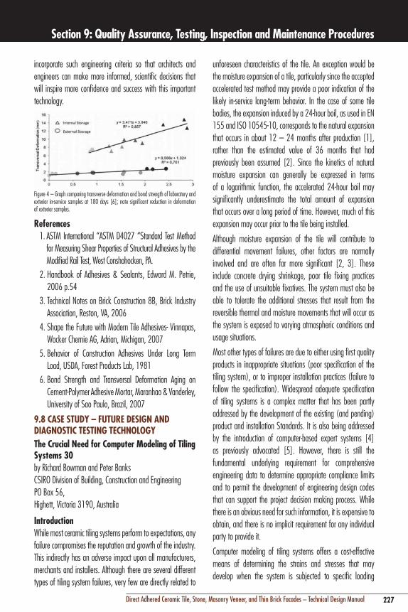
227Direct Adhered Ceramic Tile, Stone, Masonry Veneer, and Thin Brick Facades – Technical Design Manual
Section 9: Quality Assurance, Testing, Inspection and Maintenance Procedures
unforeseen characteristics of the tile. An exception would be the moisture expansion of a tile, particularly since the accepted accelerated test method may provide a poor indication of the likely in-service long-term behavior. In the case of some tile bodies, the expansion induced by a 24-hour boil, as used in EN 155 and ISO 10545-10, corresponds to the natural expansion that occurs in about 12 – 24 months after production [1], rather than the estimated value of 36 months that had previously been assumed [2]. Since the kinetics of natural moisture expansion can generally be expressed in terms of a logarithmic function, the accelerated 24-hour boil may significantly underestimate the total amount of expansion that occurs over a long period of time. However, much of this expansion may occur prior to the tile being installed.
Although moisture expansion of the tile will contribute to differential movement failures, other factors are normally involved and are often far more significant [2, 3]. These include concrete drying shrinkage, poor tile fixing practices and the use of unsuitable fixatives. The system must also be able to tolerate the additional stresses that result from the reversible thermal and moisture movements that will occur as the system is exposed to varying atmospheric conditions and usage situations.
Most other types of failures are due to either using first quality products in inappropriate situations (poor specification of the tiling system), or to improper installation practices (failure to follow the specification). Widespread adequate specification of tiling systems is a complex matter that has been partly addressed by the development of the existing (and pending) product and installation Standards. It is also being addressed by the introduction of computer-based expert systems [4] as previously advocated [5]. However, there is still the fundamental underlying requirement for comprehensive engineering data to determine appropriate compliance limits and to permit the development of engineering design codes that can support the project decision making process. While there is an obvious need for such information, it is expensive to obtain, and there is no implicit requirement for any individual party to provide it.
Computer modeling of tiling systems offers a cost-effective means of determining the strains and stresses that may develop when the system is subjected to specific loading
incorporate such engineering criteria so that architects and engineers can make more informed, scientific decisions that will inspire more confidence and success with this important technology.
Figure 4 – Graph comparing transverse deformation and bond strength of laboratory and exterior in-service samples at 180 days [6]; note significant reduction in deformation of exterior samples.
references1. ASTM International “ASTM D4027 “Standard Test Method
for Measuring Shear Properties of Structural Adhesives by the Modified Rail Test, West Conshohocken, PA.
2. Handbook of Adhesives & Sealants, Edward M. Petrie, 2006 p.54
3. Technical Notes on Brick Construction 8B, Brick Industry Association, Reston, VA, 2006
4. Shape the Future with Modern Tile Adhesives- Vinnapas, Wacker Chemie AG, Adrian, Michigan, 2007
5. Behavior of Construction Adhesives Under Long Term Load, USDA, Forest Products Lab, 1981
6. Bond Strength and Transversal Deformation Aging on Cement-Polymer Adhesive Mortar, Maranhao & Vanderley, University of Sao Paulo, Brazil, 2007
9.8 cASe STuDy – FuTure DeSIgn AnD DIAgnOSTIc TeSTIng TecHnOlOgyThe crucial need for computer Modeling of Tiling Systems 30by Richard Bowman and Peter Banks CSIRO Division of Building, Construction and Engineering PO Box 56, Highett, Victoria 3190, Australia
Introduction While most ceramic tiling systems perform to expectations, any failure compromises the reputation and growth of the industry. This indirectly has an adverse impact upon all manufacturers, merchants and installers. Although there are several different types of tiling system failures, very few are directly related to

228 Direct Adhered Ceramic Tile, Stone, Masonry Veneer, and Thin Brick Facades – Technical Design Manual
Section 9: Quality Assurance, Testing, Inspection and Maintenance Procedures
actual amount of movement and giving rise to a ‘balancing’ stress. It has been suggested [10] that sophisticated methods are little better than elementary ones for estimating the resultant stresses, because of the difficulty of accurately predicting restraint and the other variability in materials and conditions that occur in practical building situations. Thus, the essential needs are to recognize where inherent deviations are liable to occur and to determine the order of magnitude of their effects, so that adequate provision can be made for them in design. The Digests discuss movements, their sources and design strategies for accommodating them, and the causes of deformation and stress [10]; analyzes thermal and moisture effects, and includes tabulated data to assess the change of size and shape of materials [11]; and gives guidance on estimating deformations and associated forces and stresses given various stated assumptions [12]. While the Digests only cover thermal and moisture effects, they note that other types of movement also need to be considered, the most widely relevant being structural deflections, creep (especially creep-shortening of columns) and foundation movements. Also, they do not deal with the practical consequences of movements in particular parts of buildings.
Partial Analyses of Tiling System StressesBanks and Bowman [13] presented a brief review of some of the published analyses for determining the stresses within tiling systems. These vary widely in the approaches taken and as they are quite dependent on the assumptions made, each method has its limitations. Vaughan et al. [14] analyzed the tensile and compressive stresses induced by differential movement causing bending of an unrestrained layered system (as subsequently used by Harrison and Dinsdale [15]) assuming that the thickness of the system is small compared with its lateral extent, and that displacements arising from the induced curvature are small compared with the thickness. The analysis does not include any derivation of the shear and peel stresses in an adhesive layer.
Toakley and Waters [16] considered a tile run adhered to a thick solid substrate, either fully restrained laterally or unrestrained laterally, as a “bonded plate” subject to buckling due to compression following tile expansion. They referred to prior work showing that “the stresses required to produce buckling in the bonded plate were considerably greater than the
conditions. In some circumstances, partial analytical models of tiling systems may provide sufficient understanding, and at a low cost. In addition, empirical relationships have also been developed from experimental studies, for example the prediction of impact damage due to rolling wheel loads [6–9]. The advantage of any relationship that is expressed in mathematical terms is that one can readily determine the influence of a specific variable.
This paper reviews some of the published studies that relate to differential movements within tiling systems. It broadly considers some of the aspects that have limited the more widespread use of modeling techniques for developing engineered solutions for specific scenarios. It is important to recognize that while some simple theoretical models are adequate for specific purposes, others can be misleading. There is, thus, a compelling need for experimental verification, which may be hard to obtain for a number of reasons. For instance, one may obtain very different results from experiments conducted under conditions of constant temperature and relative humidity, compared to the variable conditions experienced on site. Thus, one must exercise care in applying laboratory generated results to practical situations.
There are a number of different strategic approaches that can be taken in such These include using a macroscopic perspective or more detailed analysis, and evaluation of the stresses that are generated along or across the tiling system. Such work should consider the effects of structural movements, including any pre-existing stresses within the substrate. One must particularly consider the time-dependent nature of adhesive setting reactions and differential movements. Ultimately, most approaches are acceptable and useful, as each tends to supply a partial solution to the overall problem.
Movements causing Stresses in Tiling SystemsThe Building Research Establishment has published data on the estimation of thermal and moisture movements and stresses in Digests 227 – 229 [10–12]. Recognition of the location and extent of movements in building materials and components is essential for the satisfactory design of joints and fixings and the prevention of cracking [10]. The presence of restraint offered to potential movements will determine whether differential movement occurs or whether stresses result. In most cases both effects will be present, with partial restraint limiting the
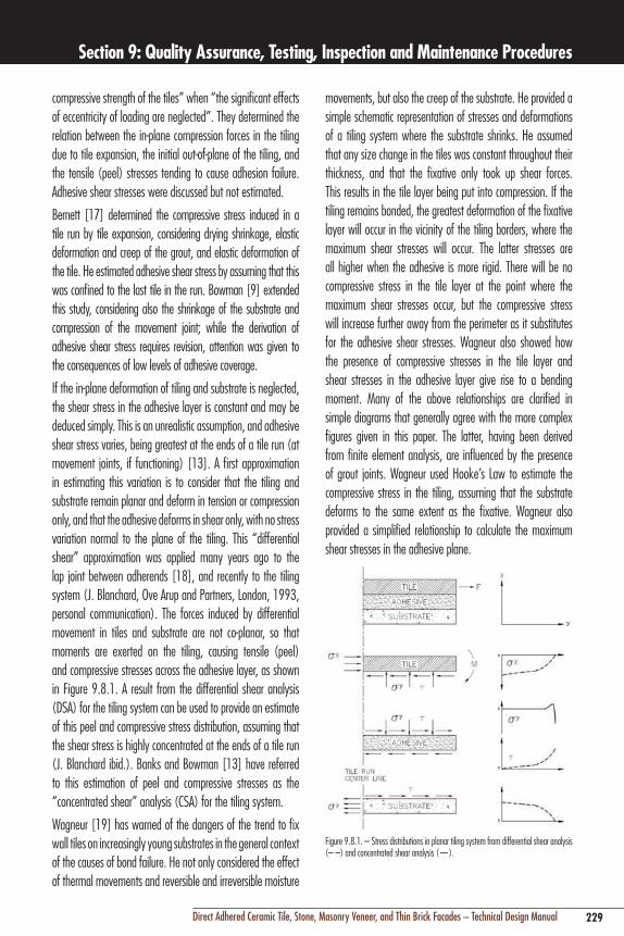
229Direct Adhered Ceramic Tile, Stone, Masonry Veneer, and Thin Brick Facades – Technical Design Manual
Section 9: Quality Assurance, Testing, Inspection and Maintenance Procedures
movements, but also the creep of the substrate. He provided a simple schematic representation of stresses and deformations of a tiling system where the substrate shrinks. He assumed that any size change in the tiles was constant throughout their thickness, and that the fixative only took up shear forces. This results in the tile layer being put into compression. If the tiling remains bonded, the greatest deformation of the fixative layer will occur in the vicinity of the tiling borders, where the maximum shear stresses will occur. The latter stresses are all higher when the adhesive is more rigid. There will be no compressive stress in the tile layer at the point where the maximum shear stresses occur, but the compressive stress will increase further away from the perimeter as it substitutes for the adhesive shear stresses. Wagneur also showed how the presence of compressive stresses in the tile layer and shear stresses in the adhesive layer give rise to a bending moment. Many of the above relationships are clarified in simple diagrams that generally agree with the more complex figures given in this paper. The latter, having been derived from finite element analysis, are influenced by the presence of grout joints. Wagneur used Hooke’s Law to estimate the compressive stress in the tiling, assuming that the substrate deforms to the same extent as the fixative. Wagneur also provided a simplified relationship to calculate the maximum shear stresses in the adhesive plane.
Figure 9.8.1. – Stress distributions in planar tiling system from differential shear analysis (– –) and concentrated shear analysis (—).
compressive strength of the tiles” when “the significant effects of eccentricity of loading are neglected”. They determined the relation between the in-plane compression forces in the tiling due to tile expansion, the initial out-of-plane of the tiling, and the tensile (peel) stresses tending to cause adhesion failure. Adhesive shear stresses were discussed but not estimated.
Bernett [17] determined the compressive stress induced in a tile run by tile expansion, considering drying shrinkage, elastic deformation and creep of the grout, and elastic deformation of the tile. He estimated adhesive shear stress by assuming that this was confined to the last tile in the run. Bowman [9] extended this study, considering also the shrinkage of the substrate and compression of the movement joint; while the derivation of adhesive shear stress requires revision, attention was given to the consequences of low levels of adhesive coverage.
If the in-plane deformation of tiling and substrate is neglected, the shear stress in the adhesive layer is constant and may be deduced simply. This is an unrealistic assumption, and adhesive shear stress varies, being greatest at the ends of a tile run (at movement joints, if functioning) [13]. A first approximation in estimating this variation is to consider that the tiling and substrate remain planar and deform in tension or compression only, and that the adhesive deforms in shear only, with no stress variation normal to the plane of the tiling. This “differential shear” approximation was applied many years ago to the lap joint between adherends [18], and recently to the tiling system (J. Blanchard, Ove Arup and Partners, London, 1993, personal communication). The forces induced by differential movement in tiles and substrate are not co-planar, so that moments are exerted on the tiling, causing tensile (peel) and compressive stresses across the adhesive layer, as shown in Figure 9.8.1. A result from the differential shear analysis (DSA) for the tiling system can be used to provide an estimate of this peel and compressive stress distribution, assuming that the shear stress is highly concentrated at the ends of a tile run (J. Blanchard ibid.). Banks and Bowman [13] have referred to this estimation of peel and compressive stresses as the “concentrated shear” analysis (CSA) for the tiling system.
Wagneur [19] has warned of the dangers of the trend to fix wall tiles on increasingly young substrates in the general context of the causes of bond failure. He not only considered the effect of thermal movements and reversible and irreversible moisture

230 Direct Adhered Ceramic Tile, Stone, Masonry Veneer, and Thin Brick Facades – Technical Design Manual
Section 9: Quality Assurance, Testing, Inspection and Maintenance Procedures
experimentally measured ultimate stress by assuming elasto-plastic or visco-plastic behavior of the adhesive material” [24]. Practical experience has shown that adhesives in tiling systems creep to relieve peak stresses [16, 17].
Standard test methods for adhesives yield average failure stresses over the adhered surface, which are not suited for comparison with theoretically obtained peak stresses to predict failure. The actual loading causing failure of a tiling system, with singular or non-singular peak stresses, can be determined from the measured failure loading of a similar physical experimental model, and the FEA peak stresses in system and model (computed with the same FEA grid size) [20]. Thus, linear-elastic FEA can be used to show the influence of changes in system parameters on maximum stresses, and thus propensity to failure, if the same FEA grid size is used in the cases compared, as shown in Appendix 1.
Naniwa et al. [25] used FEA to study the internal stress distribution caused by differential movements of exterior wall tiling systems due to the effects of two conditions: cold to hot, and wet to dry repetitive cycles. They also studied the effect of the characteristics of the system components on the stresses produced at the interfaces between them, while noting that further studies should be undertaken on the effect of stress relaxation due to creep.
Their model consisted of a two-dimensional cross-section of a wall using the half width (30 mm) of a 9mm thick tile and a 4 mm wide grout joint. The tiles were applied to a 150 mm thick concrete wall with either normal mortar or combinations of normal and lightweight mortars.
They concluded that under both sets of conditions there were two locations where delamination would tend to occur due to the in-plane shear stress: at the interface between the tile and the bonding mortar at the tile edge, and behind the tile edge at the interface between the concrete and the substrate mortar. Under cold to hot conditions, the maximum transverse stresses also occurred at the same locations. However, under wet to dry conditions, there were also significant in-plane tensile stresses at the center of the tiles at all interfaces. Under cold to hot conditions, it was found that the stress could be reduced by decreasing the elastic modulus of the mortar (increasing its deformability), especially at the interface between the concrete and the substrate mortar. Under wet to dry conditions,
Wagneur explained the debonding phenomenon in terms of progressive failure, where it is initiated at locations where the maximum shear stresses occur (free edges, flexible joints, outgoing corners, a crack or movement joint in the substrate). Once debonding is initiated at one of these locations, the segment in which the shear stresses are concentrated displaces to the immediately adjacent zone, explaining how the tiling could gradually debond. Where localized bulging occurs away from the tiling edges and discontinuities, failure will have occurred due to tensile stresses. In such situations, the rows of adhered tiles not only constitute abutments for the debonded zone, but also become more subject to shear, although they are partially restrained by being bonded (by grout) to the run of adjacent tiles, some of which are still bonded and thus effectively restrained. Wagneur indicated that if the grout is strong, it has a crushing resistance very close to that of the tiles, and that the joints absorb no deformation and undergo compressive stresses similar to those of the tiles, shear stresses being transferred to the periphery of the tiling. Where the grout is more compressible, it is more likely to absorb movement, while also subjecting the tile edges to some shear stress, albeit less than at the perimeter of the tiling.
Finite element Analyses (FeA)For the lap joint, closed-form analyses have been developed that reduce the approximations in the differential shear analysis. However, the applications of these analyses “are limited because only the simplest geometries and boundary conditions can be accommodated. For more complex situations, approximate numerical solutions become necessary” [20]. Finite element analysis (FEA) divides the system into small elements, and is suitable for adhered systems because elements with different material properties can be interfaced. FEA is available in commercial packages, and is widely applied to the stress analysis of adhesive/adherend systems [20, 21]. The application of FEA to tiling systems has been reported briefly by Van Den Berg [22] and Goto et al. [23].
In its simplest form, FEA is applied assuming linear-elastic material properties. For these properties, some peak stresses occur at adherend edges and are theoretically infinite (“singular”) [20], so increase as FEA grid size is reduced, approaching infinity for zero grid size. “In several analyses these sharp peaks were reduced to the level of the

231Direct Adhered Ceramic Tile, Stone, Masonry Veneer, and Thin Brick Facades – Technical Design Manual
Section 9: Quality Assurance, Testing, Inspection and Maintenance Procedures
uniform modulus of elasticity between elements decreased the stress slightly. The stress concentrations that led to failure were due to the homogeneity of the composite system: the more dissimilar the elements, the greater the concentration of stresses. This explains why the smaller tile sizes with more discontinuities failed at a lower deflection.
For simple spans, the mode of tiling system failure was generally an initial compressive failure of the grout leading to debonding of the tiles through shear failure of the adhesive. For continuous structures, the tensile weakness of the grout was usually the incipient failure, again followed by debonding. This is consistent with the inability of unmodified cement-based mortars to achieve acceptable results on flexible substrates, where the grout failure occurs due to the stress concentrations that build up between the tiles. However, a notable exception to this trend occurs with ceramic mosaic tiles that exhibit initial failure within the mortar layer. The thinner adhesive layer and the smaller tile size would possibly reduce the ability of stresses to distribute throughout the floor structure.
This work suggested that where tiles were polymerically bonded, the design limitations for deflection of simple span structures could be relaxed since failure would not occur until deflections occurred in excess of the practical limitations of the structure. Thus the design would be covered by the structural code and the strength of the concrete. However, for continuous substrate systems, where failure is likely to be initiated by tensile failure of the grout, the relaxation of the deflection limitations is more dependent on providing proof of the strength values of materials.
Laboratory tests were conducted on 22' x 4' x 8" (6700 x 1220 x 200 mm) reinforced concrete slabs tiled with 8" x 8" x 3/8" (200 x 200 x 9.5 mm) porcelain tiles, with two-point loading over a 20' (6.1m) span. The slabs were incrementally loaded until failure. Between the load increments, the slabs were inspected for indications such as grout failure, tile debonding and slab cracking. This provided valuable insight into the succession of events that lead to tile failure and confirmed the FEA results. In addition to the load tests, material tests were also conducted on the tile, adhesive, grout and concrete in order to determine their compressive and shear strengths.
when the drying shrinkage of both the bonding and substrate (lightweight) mortars were high, the stress increased at the interface between the substrate mortar and the concrete. Thus, repetitive drying cycles (after the infiltration of rainwater) would create extreme stresses that could result in debonding.
The use of lightweight mortar reduced the thermally induced stresses but not the moisture-induced stresses. The physical characteristics of the ideal mortar were found to be low elastic modulus, low mass density, low thermal expansion coefficient, low thermal conductivity and high specific heat.
McLaren et al. [26] used FEA to study the behavior of different materials in floor tiling systems subject to bending and deflection. Modeling of several hundred variations of three common framing systems was performed to identify the effects of floor thickness and stiffness, continuity, location of expansion joints, tile size and span length. These parameters were modulated for five permutations of adhesives and grouts, since there was particular interest in the potential benefits of recently developed polymeric materials.
They used a finite element model of the composite action of three beams (tile layer, adhesive bed and substrate) restrained by horizontal shear forces at their interfaces under a load causing deflection of a simply supported floor system. Each model was loaded to theoretical failure, defined as occurring when a stress for any component exceeded its predefined failure level.
Their initial findings included the fact that there was a significant correlation between the shear stress in the tiles and the stiffness of the grout. The shear stress distribution across the tiles was concentrated at the edges of the tiles at the grout joints. Increasing the elastic modulus of the grout reduced this stress. They were thus able to deduce that the installation of expansion joints in the middle third of a span over a simply supported substrate would only contribute to the failure of the tile configuration. From their analysis, the allowable deflection increased if an expansion joint was positioned at each support.
They also found that as the properties of the elements changed so did the stress distribution: smaller tiles (plan dimension) seemed to generate larger stresses with respect to less deflection; thicker tiles and thicker mortar beds decreased stresses; and a more

232 Direct Adhered Ceramic Tile, Stone, Masonry Veneer, and Thin Brick Facades – Technical Design Manual
Section 9: Quality Assurance, Testing, Inspection and Maintenance Procedures
show the adhesive shear stress at the tile surface, the adhesive peel stress at the substrate surface, the adhesive peel stress at the tile surface, and the tile surface tensile stress.
The latter has important implications for the positioning of strain gauges where they are used to monitor the development of stresses in the underlying adhesive bed. Since the stress is tensile rather than compressive, it could cause crazing of the glaze if excessive. Figure 7 gives the peel stress contour plot in the adhesive layer adjacent to the movement joint.
Figure 9.8.2. – Finite element analytical model for a horizontal section of a tiling system.
Figure 9.8.3 – Adhesive shear stress at tile surface for uniform tile expansion.
The laboratory data enabled refinement of the finite element model, including true modeling of a reinforced concrete slab. To verify the model, it was adapted to simulate one of the laboratory tests, where a non-linear analysis was approximated by loading the system incrementally. Where the model output indicated that a grout joint had failed, a tile had debonded, or a tensile crack had developed in the concrete, the model was changed accordingly (by virtually eliminating the failed element) and the next increment was applied. The curves predicted by FEA for the upper and lower bound of concrete strength correlated well with the laboratory test results; they were especially accurate when representing practical service load conditions.
The development of the refined mathematical model has enabled the simulation of a myriad of different installation situations without the cost and time associated with full-scale testing. The finite element modeling has shown that the behavior of ceramic tile installations using advanced latex and epoxy compounds differs significantly from traditional cement-based mortars and adhesives, and that the design rules for the traditional fixatives should not be applied to the polymeric materials. This work resulted in modifications being suggested to the relevant installation procedure. It also suggested several other areas which require further study.
Banks and Bowman [13] considered a representative floor tiling system subject to tile moisture expansion and substrate drying shrinkage, and compared the results obtained by FEA with those obtained by DSA and CSA. The stress distributions predicted by these partial analyses are shown in Figure 9.8.1. It should be noted that differential movement causes the force F, which is restrained by shear on the base of the tile, resulting in the moment M. This moment causes the end of the tile to “dig in,” resulting in peel and compressive stresses in the adhesive.
Complete adhesive coverage was assumed, the tile run was considered to be restrained laterally at the center-line of a movement joint and the substrate was unrestrained (Figure 2). The 4" (100 mm) thick concrete was modeled as a 8mm thick substrate, but with 12.5 times the elastic modulus, due to a limit on the total number of finite elements. Although tile expansion and concrete shrinkage proceed with time, and creep also occurs, the effects of any time variation of system stresses and strains were purposely neglected. Figures 3–6 respectively

233Direct Adhered Ceramic Tile, Stone, Masonry Veneer, and Thin Brick Facades – Technical Design Manual
Section 9: Quality Assurance, Testing, Inspection and Maintenance Procedures
Figure 9.8.7– Peel stress contour plot in adhesive layer adjacent to movement joint for uniform tile expansion, with the adhesive having a moderate elastic modulus 3,625 psi (25 MPa).
Figures 1 and 3–5 allow a comparison of the general shape of the curves obtained by the different analytical methods. FEA enables the effect of the grout joints to be determined. For the representative system studied, the DSA results for adhesive shear stress and grout compressive stress were 80–85% of the FEA results. Hence, in such systems, these stresses might be inferred from DSA results. The effect on adhesive peel and compressive stresses of changes in system parameters could not be inferred from CSA results. Corrections to Table 2, Banks and Bowman [13] are given in Appendix 2 to this paper.
It was found that halving the adhesive layer thickness significantly increased the adhesive shear stress while reducing the adhesive peel stress, and little changing the other stresses (except for a large increase in grout compressive stress for the low modulus adhesive). Reducing the elastic modulus of the adhesive by a factor of 20 reduced all stresses by factors of about 3 to 7. However, Divisional test results had shown that the failure shear stress of the low modulus adhesive was about a tenth of that of the moderate modulus adhesive. In such cases, the low modulus adhesive would appear more likely to fail. The partial analyses indicated that the adhesive shear, peel and compressive stresses, and the grout compressive stress, all increased appreciably for the low modulus adhesive when the movement joint spacing was increased by a factor of 4.
The authors have also concluded from mainly unpublished associated computations for this case (including those for the appended corrections), that while FEA provides a general solution, the shear, compressive and peel stresses obtained for the adhesive depended on the finite element grid size. Thus, the prediction of failure in a tiling system requires the testing to failure of a similar physical experimental model, as well as FEA of both the system and the model.
Figure 9.8.4 – Adhesive peel stress at substrate surface for uniform tile expansion.
Figure 9.8.5 – Adhesive peel stress at tile surface for uniform tile expansion.
Figure 9.8.6 – Tile surface tensile stress for uniform tile expansion.

234 Direct Adhered Ceramic Tile, Stone, Masonry Veneer, and Thin Brick Facades – Technical Design Manual
Section 9: Quality Assurance, Testing, Inspection and Maintenance Procedures
Doubling the adhesive layer thickness significantly reduced the shear and compressive adhesive stresses at both the tile and substrate surfaces. The peel stresses decreased slightly, unlike the case for uniform tile expansion where the peel stresses increased significantly. Reducing the elastic modulus of the adhesive by a factor of 20 reduced the adhesive stresses by a factor of about 5. It also reduced the grout compressive stress by 20%, while decreasing the compression in the surface of the tile towards tension values. The reduction of the adhesive coverage to 50% significantly increased adhesive shear and peel stresses, the increases being greatest when the partial coverage was at the ends of each tile. The authors have concluded, from unpublished associated computations for this case, that while FEA provides a general solution, the compressive stresses obtained for the adhesive depended on the finite element grid size (but not the shear and peel stresses).
Summary of Past FeA StudiesThe above examples of finite element modeling reveal quite different approaches. It can be seen that the trends that are evident in one loading condition may be quite different in another practical situation. Furthermore, in most practical situations, there will be several different types of movements occurring simultaneously. Tiling systems are very complex, and it must be noted that the past studies have made several simplifying assumptions. These include an assumption that the substrate is stress-free at the time of tiling, and that it is planar and has uniform thermal and moisture movements. The adhesive is assumed to have elastic rather than visco-elastic properties, and the assumed uniform characteristics are those that are determined under laboratory conditions at one point in time. Adhesive shrinkage is generally assumed to be negligible. The ceramic tile is assumed to be a stress-free rectangular prism with planar surfaces and two pairs of parallel edges. It is assumed that the grout joints are free of all adhesive. Movements due to structural deflections, creep, foundation movements and wind loading have generally been neglected.
McLaren et al. [26] noted that there are great variations in the published mechanical properties and ultimate stresses of tiles, adhesives and grouts, as is evident elsewhere [11, 19]. Even where the properties are determined for specific materials, one should recognize that laboratory preparation and loading conditions are quite different to those that occur in practice, and there may be a difference in performance.
Bowman and Banks [27] considered a representative external wall tiling system subject to thermally induced non-uniform differential movement (from tile transient heating), with full and partial adhesive coverage, using similar constraints to those in Figure 2 and similar assumptions to those in Ref. [13].
Figures 8 and 9 depict the adhesive shear and normal stresses at the tile surface. Figure 10 gives the normal stress contour plot in the adhesive layer adjacent to the movement joint. Figure 11 gives a similar plot where there is only 50% adhesive coverage concentrated at the tile ends. It can be seen that the reduced coverage significantly increases the stress levels. Furthermore, the location of the maxima and minima differ from that induced by uniform differential movement (Figure 7). The consequence of partial adhesive coverage also results in a different tensile stress distribution at the tile surface. Unlike the case for uniform tile expansion (Figure 6), the stresses in Figure 12 are compressive. This is due to the tile surface expanding more than the rest of the tile due to the assumed temperature profile through the tile.
Figure 9.8.8 – Adhesive shear stress at tile surface for non-uniform tile expansion.
Figure 9.8.9 – Adhesive normal stress at tile surface for non-uniform tile expansion.

235Direct Adhered Ceramic Tile, Stone, Masonry Veneer, and Thin Brick Facades – Technical Design Manual
Section 9: Quality Assurance, Testing, Inspection and Maintenance Procedures
Figure 9.8.12 – Tile surface tensile stress for non-uniform tile expansion, with 50% adhesive coverage concentrated at the tile centers.
It should be noted that the draft European Norms for ceramic tiling adhesives do not require the determination of the shear strength of cementitious adhesives, or the tensile strength of dispersion adhesives. The logic for this is hard to determine given some of the conclusions that can be drawn from the modeling of tiling systems. It seems evident that the primary cause for tiling system failures is related to both shear and tensile strength. In practical situations, failures probably occur when strain rates exceed creep relief rates [17].
Figure 9.8.13 – Exaggerated deformations in a loaded single lap joint, and resultant shear stresses.
Prediction of Stress and Strain in Tiling SystemsShear Deformation MethodSome adhesive manufacturers have used a comparison of unrestrained differential movement with the shear deformation of an adhesive at failure to predict whether the adhesive would fail in the system. This method is deficient in several respects:
1. Adhesive shear strain (deformation/ thickness) determines failure, rather than adhesive shear deformation.
Figure 9.8.10 – Normal stress contour plot in adhesive layer adjacent to movement joint for non-uniform tile expansion, with the adhesive having a moderate elastic modulus (25 MPa).
Figure 9.8.11 – Normal stress contour plot in adhesive layer adjacent to movement joint for non-uniform tile expansion, with 50% adhesive coverage concentrated at the tile ends, and the adhesive having a moderate elastic modulus 3,625 psi (25 MPa).
Adhesive evaluation for Tiling SystemsAdhesive loading in Tiling SystemsIn tiling systems, differential movement between tiles and substrate may be caused by irreversible movement of tiles or substrate, transient heating, wetting or structurally induced bending of the system. Different patterns of shear and tensile (peel) stresses are induced in the adhesive layer, each resulting in adhesive deformation and possibly failure. Failure prediction requires prediction of maximum stresses or strains, and knowledge of failure values.
Adhesive TestingThere are standard tests for the shear and tensile strengths of adhesives, which produce differential movement loading by force. Neither test produces pure shear or tensile strain, and the resulting stresses are not uniform over the specimen, though these effects are small for the tensile test. Figure 13 is a classic diagram for the deformations and shear stresses occurring in a lap joint on shear loading. Average values of failure stresses over a specimen are obtained, which are not comparable with the peak shear values resulting in failure in shear tests or tiling systems.
These tests are useful for the comparison of adhesives. This comparison is under ideal conditions and with small specimens. A resulting ranking of adhesives depends on the ambient and other conditions used.

236 Direct Adhered Ceramic Tile, Stone, Masonry Veneer, and Thin Brick Facades – Technical Design Manual
Section 9: Quality Assurance, Testing, Inspection and Maintenance Procedures
Finite element AnalysisThis numerical method, available in commercial computer packages, enables the stress and strain distribution in a tiling system to be determined for given differential movement and assumed material properties. The computation is substantial even where only elastic material properties are considered. Some results depend on the finite element grid size used. Actually, the plastic and viscous properties of the adhesive need to be considered to predict adhesive failure. Furthermore, it should be recognized that many failures will tend to occur due to an irreversible process of localized bond failure where there is a progressive reduction in the total bonded area.
However, even assuming elastic properties, results can be quickly obtained for the effects of changes in system parameters, showing propensity to failure. These trends have been found to differ between uniform tile expansion [13] and non-uniform tile expansion (from transient heating) [27], but mixed modes of differential movement are likely to occur in practice. When one considers all of the possible sources of movements, the inherent differences in material properties, and the potential variations arising from differences in construction techniques and installation practices, one can appreciate the enormity of the problem of predicting the performance of tiling systems. However, given this level of complexity, the best approach appears to be to determine the influence of distinct aspects of the overall behavior, before developing a composite model to understand a particular situation.
Physical experimental ModelThe maximum stresses predicted using FEA with elastic properties can be used to predict failure when a physical experimental model similar to the tiling system is tested to failure and similarly analyzed [20], as detailed in Appendix 1.
The standard adhesive shear test does not provide a similar experimental model, because it is loaded by force, producing a combination of shear and tensile stresses different from that produced by direct differential movement, as occurs in a tiling system. Hence a practical physical experimental model for use in predicting adhesive failure in tiling systems remains to be devised.
2. The unrestrained differential movement of a tiling system is much greater than the resulting shear deformation of the adhesive, because the tiles and substrate suffer tensile or compressive deformation when restrained. For example, in the case presented in line 2 of the Table in Appendix 2, the adhesive shear deformation is 63% of the system differential movement.
3. Studies of failed tiling systems suggest that tiling adhesive fails in a combination of shear and peel, indicating that shear strain is not the sole critical factor determining failure.
Differential Movement DeterminationAdhesive manufacturers who are using the above shear deformation method have calculated differential movement using the length of a tile, whereas the distance between movement joints determines differential movement. These manufacturers have considered differential movement induced by heating of the tiles alone. This occurs during a transient period before the substrate is also heated. In such transient heating, the tiles are non-uniformly heated, with the outer face heated and the inner face unheated, like the substrate. As a result, a transient temperature profile is set up through the tile. For example, in Figure 14, the outer face of the tile is at 140°F (60°C), while the inner face and substrate are still at 68°F (20°C). The average temperature rise of the tile would then be near 68°F (20°C), not 104°F (40°C) as assumed by the adhesive manufacturers. When the substrate begins to heat, the differential movement may reduce, because the thermal expansion coefficient of concrete is greater than that of the ceramic tile. Therefore, manufacturers applying the shear deformation method incorrectly estimate applied differential movement.
Figure 14 – Temperature profile in tiling system.

237Direct Adhered Ceramic Tile, Stone, Masonry Veneer, and Thin Brick Facades – Technical Design Manual
Section 9: Quality Assurance, Testing, Inspection and Maintenance Procedures
While partial analytical methods can be used to obtain an indication of the likely adhesive shear stresses, one has to be very aware of the assumptions that have been made and the limitations that thus apply.
Such methods may provide more cost effective solutions in some circumstances. Assumptions also have to be made with respect to finite element modeling, and there are again limitations that one must recognize. One must complement the FEA with tests to failure of a physical experimental model, but such procedures have still to be fully developed. FEA can assist in product development as it provides a means of rapidly and cost effectively determining the relative effect of modifying a system parameter, prior to confirmatory testing. A better knowledge of the time-dependent behavior of the system components will allow development of more reliable models, assisted by the continued development of more powerful finite element software.
FEA indicates that there is a potential deficiency in draft European Norms for ceramic tiling adhesives since they do not require the determination of the shear strength of cementitious adhesives, or the tensile strength of dispersion adhesives. The logic for this is hard to determine given some of the conclusions that can be drawn from the modeling of tiling systems.
The identification of locations where critical stresses will occur is important, because one can take particular care to ensure that best work practices are followed at these locations. However, this is only a partial solution. Analysis of the stresses in adhesive joints is essential for efficient design, particularly if realistic factors of safety are to be used. In the design process it is important to know unambiguously the mechanical properties of the materials used. Adhesive manufacturers’ product literature often extols their technical virtuosity. Sadly, their contributions to the scientific literature are inconsistent with these raised consumer expectations. If consumers are to realize their expectations of improved life cycle performance, more information must be made available to designers. This should instill greater confidence in architects, and enable tiles to be more widely used in applications such as high-rise external facades.
In this context, it is worth noting that since the tensile stress on the tile surface is not uniform (Figure 6), the use of strain gauges to determine the stresses occurring within tiling systems, as used in Refs. [15, 28], might be influenced by the location and orientation of the strain gauges.
conclusionsPartial analytical approaches can be used to estimate the shear stress concentrations in tiling systems, but are presently inadequate for predicting peel stresses. Therefore, FEA becomes necessary for predicting all the stresses that occur within tiling systems and their concentrations, particularly in the critically loaded regions of tiling runs.
At the present stage of progress in the finite element modeling of tiling systems, it is to be expected that particular investigations will concentrate on specific aspects of the overall complex composite problem. Thus McLaren et al. [26] have considered systems with differential movement caused by bending of the system, while Naniwa et al. [25] have looked at a cross section half a tile wide in considering the effect of differential movement on a tiling system. Banks and Bowman [13, 27] have also considered differential movement, but over the distance between movement joints, finding that the stress distribution contours for uniform tile expansion [13] and non-uniform tile expansion (from transient heating) [27] are quite different; also, the adhesive stresses increase from tile to tile such that they are at a maximum close to movement joints. Such modeling allows several conclusions to be drawn about the design of tiling systems and the selection of materials. Naniwa et al. [25] have obtained data that can be used to improve the design of external wall tiling systems. McLaren et al. [26] were able to demonstrate the role of the grout joints in the failure sequence that occurs when a floor bends. They showed that the design rules for traditional cement-based adhesives should not be applied to recently developed polymeric adhesives, and suggested several modifications to the design guidelines. Thus, while the approaches taken have been very different, all of them are useful as each has provided further insight into a specific aspect of the overall (highly complex)problem.

238 Direct Adhered Ceramic Tile, Stone, Masonry Veneer, and Thin Brick Facades – Technical Design Manual
Section 9: Quality Assurance, Testing, Inspection and Maintenance Procedures
21. Buchman, A., Weinstein, F., Hönigsberg, I., Höldengraber, Y. and Dodiuk, H.: J. of Adhesion Science and Technology, 1993, 7, 385
22. Van Den Berg, F.J.: Symposium on Ceramic Tile Installation, South Africa, September 1985, Institute of South African Architects
23. Goto, Y., Yamazaki, K. and Ishida, H.: Proc. 3rd World Congress on Ceramic Tile Quality, Castellon, 1994, Vol. II, 249
24. Weitsman, Y.: J. of Adhesion, 1981, 11, 279
25. Naniwa, R., Hayashi, Y., Yamazaki, T. and Takada, E.: Proc. Int. Conf. on Building Envelope Systems and Technology, Singapore, December 1994, 195
26. McLaren, M.G., McLaren Jr, M.G. and Deierlen, G.: presented to Int. Conf. on Building Envelope Systems and Technology, Singapore, Dec. 1994
27. Bowman, R. and Banks, P.J.: Proc. Int. Conf. on Building Envelope Systems and Technology, Singapore, December 1994, 73
28. Uher, T.: J. Aust. Cer. Soc., 1985, 21, 35
references1. Bowman, R. and Westgate, P.: Proc. Int. Ceram. Conf.
AUSTCERAM 94, Sydney, 1265
2. Bowman, R.: Proc. 2nd World Congress on Ceramic Tile Quality, Castellon, 1992, 459
3. Bowman, R.: Ceramica Acta, 1993, 5(4–5), 37
4. Bowman, R. and Cass, C.: Ceramic Tiles Today, Nov. 1995, 38
5. Bowman, R. and Leslie, H.G.: Proc. 1st World Congress on Ceramic Tile Quality, Castellon, 1990, 83
6. Waubke, N.V.: Ber. Dt. Keram. Ges., 1975, 52, 290
7. Waubke, N.V.: Ber. Dt. Keram. Ges., 1977, 54, 37
8. Uhrig, R. and Waubke, N.V.: cfi/Ber. DKG, 1983, 60, 357
9. Bowman, R.: Key Eng. Matls, 1990, 48–50, 173
10. Anon.: Building Research Establishment Digest 227, July 1979
11. Anon.: Building Research Establishment Digest 228, August 1979
12. Anon.: Building Research Establishment Digest 229, September 1979
13. Banks, P.J. and Bowman, R.: Proc. Int. Ceram. Conf. AUSTCERAM 94, Sydney, 1259
14. Vaughan, F., Smith, F.T.M. and Dinsdale, A.: The A.T. Green Book, B. Ceram. R. A., Stoke-on-Trent, 1959, 150
15. Harrison, R. and Dinsdale, A.: Internal Wall Tile Fixing, BCRA Special Publication No. 79, 1972
16. Toakley, A.R. and Waters, E.H.: Building Science, 1973, 8, 269
17. Bernett, F.E.: Am. Ceram. Soc. Bull., 1976, 55, 1039
18. Volkerson, O.: Luftfahrtforschung, 1938, 15, 41
19. Wagneur, M.: CSTC Magazine, Autumn 1995, 23
20. Penado, F.E. and Dropek, R.K.: Engineered Materials Handbook: Volume 3 – Adhesives and Sealants, eds. H. F. Brinson et al., ASM International, USA, 1990, pp. 477–500

239Direct Adhered Ceramic Tile, Stone, Masonry Veneer, and Thin Brick Facades – Technical Design Manual
Section 9: Quality Assurance, Testing, Inspection and Maintenance Procedures
There is a need to gain experience in applying the method to tiling systems. This will involve designing and conducting experiments suited to representative tiling systems and LE-FEA.
APPenDIX 2: corrections to "Prediction of Failure in Tiling Systems" [13]1. Stresses for 1/8" (3 mm) Adhesive-layer ThicknessFor the 1/8" (3 mm) adhesive-layer thickness, a FEA grid size of 2 x 0.04" (1 mm) was used instead of the 2 x 0.02" (0.5 mm) size indicated in Table 1. The FEA determinations for this layer thickness have been repeated with the indicated grid size, increasing adhesive peel and compressive stresses significantly. The corrected results are shown in the revised Table 2 given below. The effect of change in adhesive-layer thickness is no longer qualitatively the same in results from both FEA and CSA for adhesive compressive stress. Therefore, the effect of changes in system parameters on this stress cannot be inferred from CSA results. Also, the reduction in adhesive peel stress from halving adhesive-layer thickness for the low-modulus adhesive is no longer small, but smaller than for the moderate-modulus adhesive.
2. Modulus e of equivalent Tile in DSAThe modulus E of the equivalent tile (combining tiles and grout joints) used in DSA depends on the number of tiles in a tile run, because the number of grout joints is one less than the number of tiles. The value of equivalent tile modulus used in the paper 15.8 GPa (2,290,000 psi) applies for a tile run with very many tiles. For the tile run with four tiles analyzed, the equivalent tile modulus is 5.5% greater, and the stresses predicted by DSA are greater by up to the same proportion for the moderate modulus adhesive. For the low-modulus adhesive, the predicted stresses are greater or less by up to a few per cent. The corrected stresses are given in the above table.
3. Movement Joint Width and SpacingThe movement joint width used was 1/4" (6 mm), instead of the 1/8" (3 mm) indicated in Table 1. A check in one case showed that reducing this width from 1/4" – 1/8" (6 mm – 3 mm) had a negligible effect on the maximum values of all stresses, except tile-surface tensile stress, for which the maximum increased by 2.6%. The movement joint spacing has been corrected in the table below.
APPenDIX 1:Method for Failure Prediction in Tiling Systems (After [20])This method requires the assumption of the particular peak stress in the tiling system causing failure of the system. Making this assumption is assisted by the inspection of failed cases of the tiling system. A physical experimental model of the tiling system is constructed that uses the same materials as the actual system. Also, if the peak stress assumed to cause failure is “singular,” then its strength (defining peak sharpness) is made the same in the model and the actual system. Considering system loading from differential movement and/or bending effects, it follows that for the model (m) and actual system (as):
(a) The failure peak stress (the actual peak stress for the failure loading) is the same, thus: {actual peak stress for failure loading}m
= {actual peak stress for failure loading}as (1)
(b) The ratio of actual peak stress for loading L to the linear-elastic FEA (LE-FEA) predicted peak stress for loading L is the same, where loading L is any given loading, thus, from (1) and (b):
{LE-FEA predicted peak stress for failure loading}m
= {LE-FEA predicted peak stress for failure loading}a (2)
(c) The LE-FEA predicted peak stress at failure loading is given by:
(LE-FEA predicted peak stress for loading L) (failure loading)/(loading L); thus, from (2) and (c):
{(LE-FEA predicted peak stress for loading L) (failure loading)/(loading L)}m
= {(LE-FEA predicted peak stress for loading L) (failure loading)/(loading L)}as (3)
Therefore, the predicted failure loading of the actual system is given by:
where the same FEA grid size is used in the LE-FEA of the model and the actual system.

240 Direct Adhered Ceramic Tile, Stone, Masonry Veneer, and Thin Brick Facades – Technical Design Manual
Section 9: Quality Assurance, Testing, Inspection and Maintenance Procedures
corrected Table 2Maximum stress (3D) in the representative ceramic floor tiling system (Table 1), with complete adhesive coverage, 0.03% tile moisture expansion and 0.01% substrate shrinkage. Results from FEA in bold type; results from DSA in italics; and (results from CSA in parentheses).
Adhesive Adhesive StressesTile Surface
Tensile grout
Movement Joint Compressive Spacing (m)
Modulus E (MPa)
Layer Thickness (mm) Shear (MPa) Peel (MPa)
Compressive (MPa)
Stress (MPa) Stress (MPa)
1.215 25.0 6.0 0.325 (0.143) (0.689) 8.9
3.0 0.533 0.469 0.637 (0.235) 1.119 (1.132)
1.16 11.8 10.3
1.5 0.799 0.665 0.288 (0.335)
0.980 (1.708)
1.13 12.6 11.1
1.25 6.0 0.034 (0.005) (0.022) 1.3
3.0 0.074 0.064
0.103 (0.012)
0.134 (0.057)
0.29 2.8 2.3
1.5 0.134 0.113 0.077 (0.028)
0.132 (0.057)
0.35 4.8 4.0
4.851 25.0 3.0 0.462 (0.252) (1.215) 10.9
1.215 0.469 (0.235) (1.132) 10.3
4.851 1.25 0.103 (0.050) (0.241) 9.7
1.215 0.064 (0.012) (0.057) 2.3

241Direct Adhered Ceramic Tile, Stone, Masonry Veneer, and Thin Brick Facades – Technical Design Manual
Section 10: Case Study and Troubleshooting
241Direct Adhered Ceramic Tile, Stone, Masonry Veneer, and Thin Brick Facades – Technical Design Manual
Photo-Project: Brooklyn Children’s Museum, Brooklyn, NY 2007 Architect: Rafael Vinoly Architects.

242 Direct Adhered Ceramic Tile, Stone, Masonry Veneer, and Thin Brick Facades – Technical Design Manual
Section 10: Case Study and Troubleshooting
10.1 CaSe STudy – Brooklyn Children'S MuSeuMCase Study 1 – Aerial view of Brooklyn Children’s Museum. Installation of air barrier over exterior rated sheathing (3/4" [19 mm] exterior glue plywood) for the vertical façade portion of the installation. The LATICRETE® Plaza & Deck System was utilized to create the unique contoured tiled roof and gutter assembly.
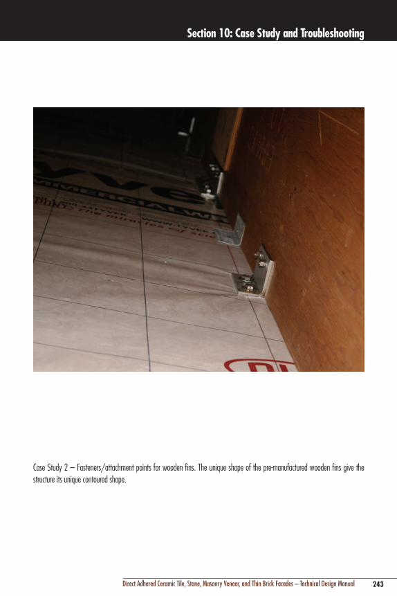
243Direct Adhered Ceramic Tile, Stone, Masonry Veneer, and Thin Brick Facades – Technical Design Manual
Section 10: Case Study and Troubleshooting
Case Study 2 – Fasteners/attachment points for wooden fins. The unique shape of the pre-manufactured wooden fins give the structure its unique contoured shape.

244 Direct Adhered Ceramic Tile, Stone, Masonry Veneer, and Thin Brick Facades – Technical Design Manual
Section 10: Case Study and Troubleshooting
Case Study 3 – Pre-manufactured wooden fins are installed followed by lateral supports which help to stabilize and provide added rigidity to the façade structure.

245Direct Adhered Ceramic Tile, Stone, Masonry Veneer, and Thin Brick Facades – Technical Design Manual
Section 10: Case Study and Troubleshooting
Case Study 4 – The installation of a water resistive barrier (e.g. 15 lb builders felt) is placed over the lateral structural elements.
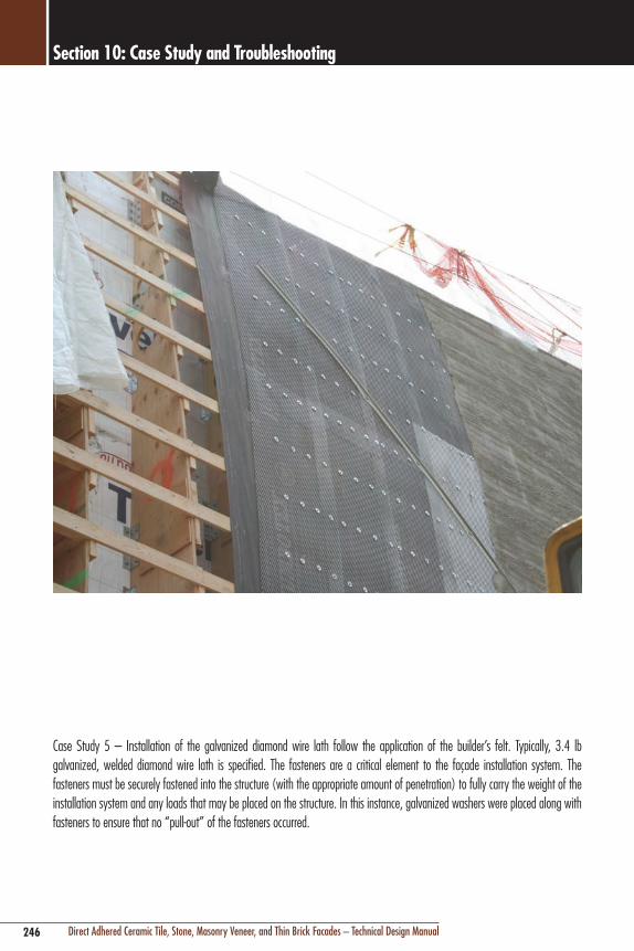
246 Direct Adhered Ceramic Tile, Stone, Masonry Veneer, and Thin Brick Facades – Technical Design Manual
Section 10: Case Study and Troubleshooting
Case Study 5 – Installation of the galvanized diamond wire lath follow the application of the builder’s felt. Typically, 3.4 lb galvanized, welded diamond wire lath is specified. The fasteners are a critical element to the façade installation system. The fasteners must be securely fastened into the structure (with the appropriate amount of penetration) to fully carry the weight of the installation system and any loads that may be placed on the structure. In this instance, galvanized washers were placed along with fasteners to ensure that no “pull-out” of the fasteners occurred.

247Direct Adhered Ceramic Tile, Stone, Masonry Veneer, and Thin Brick Facades – Technical Design Manual
Section 10: Case Study and Troubleshooting
Case Study 6 – The installation of pre-fabricated expansion joint screed strips now takes place in the installation sequence. The expansion joint strips define the tiled areas/pattern.

248 Direct Adhered Ceramic Tile, Stone, Masonry Veneer, and Thin Brick Facades – Technical Design Manual
Section 10: Case Study and Troubleshooting
Case Study 7 – Close up view of the diamond metal lath/fasteners and expansion joint strips.

249Direct Adhered Ceramic Tile, Stone, Masonry Veneer, and Thin Brick Facades – Technical Design Manual
Section 10: Case Study and Troubleshooting
Case Study 8 – Latex fortified portland cement scratch and brown coat. The use of a LATICRETE® latex fortified portland cement based leveling mortar is used to create the profile of the tiled façade system. This is a two coat process. The scratch coat is applied first (maximum thickness is generally 1/2" [12 mm]), scratched up with a mortar scratching tool to create a rough profile (which aids in the bonding of the brown coat) and allowed to harden (typically 12 – 24 hours at 70°F [21°C]). The brown coat is also applied in a 1/2" [12 mm] thickness, floated to desired point and allowed to harden. Proper application of the scratch and brown leveling coats will result in an aesthetically pleasing tile or stone finish.

250 Direct Adhered Ceramic Tile, Stone, Masonry Veneer, and Thin Brick Facades – Technical Design Manual
Section 10: Case Study and Troubleshooting
Case Study 9 – Progress of the latex fortified portland cement scratch and brown coat.

251Direct Adhered Ceramic Tile, Stone, Masonry Veneer, and Thin Brick Facades – Technical Design Manual
Section 10: Case Study and Troubleshooting
Case Study 10 – Once the scratch and brown coat are installed, it is now ready to receive the waterproofing membrane. The leveling mortars are typically allowed to cure 48 to 72 hours at 70°F (21°C) prior to the installation of the waterproofing membrane. Penetrations, drains, lights, windows, pipes, etc…are prepared first. In this instance LATICRETE® 9235 Waterproofing Membrane, the gold standard in waterproofing membranes for tile and stone installations, is being used. Once the pre-treated areas are dry, the main membrane application can commence. Notice how the fabric component is pre-cut in order to be placed quickly into the freshly applied liquid component. Generally, the waterproofing membrane is overlapped by a minimum of 2" (50 mm) onto adjacent areas. The leveling mortar is typically dampened with a sponge and clean water in an effort to reduce the suction of the concrete and allow the membrane to remain workable for an extended period of time.

252 Direct Adhered Ceramic Tile, Stone, Masonry Veneer, and Thin Brick Facades – Technical Design Manual
Section 10: Case Study and Troubleshooting
Case Study 11 – The penetrations are sealed with a suitable flexible sealant. Generally, 100% silicone sealant (e.g. LATICRETE® LATASIL™ with LATICRETE 9118 Primer) or urethane sealant with non-solvent based primers can be used. All precautions to create a complete watertight application must be taken to ensure a successful installation.

253Direct Adhered Ceramic Tile, Stone, Masonry Veneer, and Thin Brick Facades – Technical Design Manual
Section 10: Case Study and Troubleshooting
Case Study 12 – Movement joints are also included in the pre-treated areas. The waterproofing membrane is looped down into the movement joint (to accommodate any potential movement). The waterproofing membrane must be given enough “slack” when looped into the joint to accommodate the anticipated movement. The waterproofing membrane is then lapped onto the concrete/mortar bed joint flanks and horizontal areas by at least 2 – 4" (50 – 100 mm) to receive the main waterproofing membrane treatment.

254 Direct Adhered Ceramic Tile, Stone, Masonry Veneer, and Thin Brick Facades – Technical Design Manual
Section 10: Case Study and Troubleshooting
Case Study 13 – The tile installation can now begin. A high strength liquid latex fortified thin set mortar (e.g. LATICRETE® 254 Platinum or LATICRETE 4237 Latex Additive mixed with LATICRETE 211 Powder) suitable for exterior applications is used.

255Direct Adhered Ceramic Tile, Stone, Masonry Veneer, and Thin Brick Facades – Technical Design Manual
Section 10: Case Study and Troubleshooting
Case Study 14 – Grouting phase – LATICRETE SpectraLOCK® PRO Grout† in a custom color matched grout was used for the grouting of the façade. The project design allowed for the use of an epoxy grout (e.g. due to the ‘vented’ wall cavity) on this project. In addition, the project required a brilliant yellow grout that is only attainable with epoxy grout technology. Typically, a latex fortified portland cement grout would be used for the grout (e.g. LATICRETE PermaColor™ Grout^). The photo also depicts the progression of the installation at different stages.
† United States Patent No. 6881768 (and other Patents).^ United States Patent No. 6784229 B2 (and other Patents).

256 Direct Adhered Ceramic Tile, Stone, Masonry Veneer, and Thin Brick Facades – Technical Design Manual
Section 10: Case Study and Troubleshooting
Case Study 15 – Installation of flexible sealant at the movement joints. The joint is masked off to facilitate the installation. The joint is packed with a compressible foam backer rod and then treated with the sealant. The sealant was also custom color matched to the grout and tile.

257Direct Adhered Ceramic Tile, Stone, Masonry Veneer, and Thin Brick Facades – Technical Design Manual
Section 10: Case Study and Troubleshooting
Case Study 16 – Completed installation.
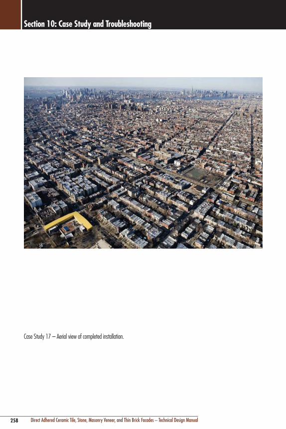
258 Direct Adhered Ceramic Tile, Stone, Masonry Veneer, and Thin Brick Facades – Technical Design Manual
Section 10: Case Study and Troubleshooting
Case Study 17 – Aerial view of completed installation.

259Direct Adhered Ceramic Tile, Stone, Masonry Veneer, and Thin Brick Facades – Technical Design Manual
Section 10: Case Study and Troubleshooting
Figure 10.1 – Exterior applications must be protected from the elements during the installation and curing periods. Protection was placed around the scaffolding tol protect the application from direct sunlight, wind and rain/snow. In addition, heating the space allows work to take place in cold conditions.
10.2 TrouBleShooTing PiCTorialTroubleshooting Pictorial

260 Direct Adhered Ceramic Tile, Stone, Masonry Veneer, and Thin Brick Facades – Technical Design Manual
Section 10: Case Study and Troubleshooting
Figure 10.2 – Exterior view of tenting/wrapped scaffolding. Temporary heating units must be properly vented. Tenting/heating allows the installation products to cure properly.

261Direct Adhered Ceramic Tile, Stone, Masonry Veneer, and Thin Brick Facades – Technical Design Manual
Section 10: Case Study and Troubleshooting
Figure 10.3 – Improper flashing to the window frame left large gaps between the waterproofing membrane and the window frame. The liquid applied waterproofing membrane must be properly applied/flashed/sealed into adjacent building elements to create a watertight seal. Typically, a suitable 100% silicone or urethane sealant is used to bridge/help tie into various building elements.

262 Direct Adhered Ceramic Tile, Stone, Masonry Veneer, and Thin Brick Facades – Technical Design Manual
Section 10: Case Study and Troubleshooting
Figure 10.4 – Improper bedding of stone finish. Industry standards require a minimum 95% adhesive mortar coverage per ANSI A108.5 standards. Voids left in the adhesive mortar will create cavities that cannot resist the effects of freeze/thaw cycles. In addition, voids in the setting bed can create opportunities for the potential damaging effects of thermal or moisture expansion that can effect the assembly.

263Direct Adhered Ceramic Tile, Stone, Masonry Veneer, and Thin Brick Facades – Technical Design Manual
Section 10: Case Study and Troubleshooting
Figure 10.5 – Improper treatment of expansion joint. Tiles were installed in a manner that bridged the movement joint in the back-up structure. A movement joint treated with an appropriate flexible sealant is required in these areas.

264 Direct Adhered Ceramic Tile, Stone, Masonry Veneer, and Thin Brick Facades – Technical Design Manual
Section 10: Case Study and Troubleshooting
Figure 10.6 – Lack of proper expansion joint movement can result in significant safety issues for people and property.

265Direct Adhered Ceramic Tile, Stone, Masonry Veneer, and Thin Brick Facades – Technical Design Manual
Section 10: Case Study and Troubleshooting
Figure 10.7 – Porcelain mosaic tiles installed over fabric reinforced liquid applied waterproofing membrane. High performance portland cement based latex thin set mortar combed in one direction to maximize coverage.
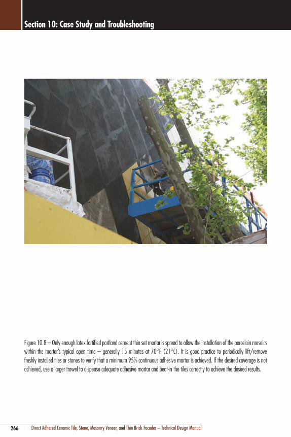
266 Direct Adhered Ceramic Tile, Stone, Masonry Veneer, and Thin Brick Facades – Technical Design Manual
Section 10: Case Study and Troubleshooting
Figure 10.8 – Only enough latex fortified portland cement thin set mortar is spread to allow the installation of the porcelain mosaics within the mortar’s typical open time – generally 15 minutes at 70°F (21°C). It is good practice to periodically lift/remove freshly installed tiles or stones to verify that a minimum 95% continuous adhesive mortar is achieved. If the desired coverage is not achieved, use a larger trowel to dispense adequate adhesive mortar and beat-in the tiles correctly to achieve the desired results.

267Direct Adhered Ceramic Tile, Stone, Masonry Veneer, and Thin Brick Facades – Technical Design Manual
Section 10: Case Study and Troubleshooting
Figure 10.9 – Sealant in the movement joints. In order for the sealant to maintain its functional ability, the joint must be correctly designed. Namely:
1. The joint depth must be at least ½ the width of the joint. Therefore, if a joint is 1/2" (12 mm) wide, the joint depth must be at least 1/4" (6 mm).
2. Closed cell polyurethane backer rod should be used in joints with sufficient depth. The backer rod must fit neatly into the joint without compacting. Bond breaker tape can be used in joints that will not allow the use of backer rod.
3. Sealant primer is generally used in wet area applications.
4. The sealant and primer must be suitable for wet area applications and must not bond to the backup materials.
5. Use a class 25 sealant. This is a sealant that can withstand an increase and decrease of +/- 25% of joint width. It is important to note that in some cases, a sealant must be able to withstand an even greater increase / decrease rate of +/- 25%. The project engineer can determine the rate of movement and specify a sealant appropriate for the application.
6. Joint flanks (tile edges) to which the sealant will bond, must be kept clean and dry.
7. According to the Tile Council of North America’s Movement Joints – Vertical and Horizontal Detail EJ-171, typical exterior movement joints should be spaced every 8' – 12' (2.6 – 4 m) in each direction and against all restraining surfaces. Movement joints that are 8' (2.6 m) on center should be a minimum of 3/8" (9 mm) wide and joints that 12' (4 m) on center should be a minimum of 1/2" (12 mm) wide. In addition, minimum joint widths must be increased 1/16" (1.5 mm) for each 15ºF (5ºC) tile surface temperature change greater than 100ºF (37ºC) between summer high and winter low.

268 Direct Adhered Ceramic Tile, Stone, Masonry Veneer, and Thin Brick Facades – Technical Design Manual
Section 10: Case Study and Troubleshooting
Figure 10.10 – Efflorescence (soluble salts) becomes apparent in this façade when the tile and grout dries out. Typically, when wet, the efflorescence remains in solution and is not visibly apparent. However, upon drying, the soluble salts crystallize and becomes manifest as efflorescence. Proper attention to cure times, protection of freshly installed materials and use of a waterproofing membrane can help to negate the unsightly effects of efflorescence.

269Direct Adhered Ceramic Tile, Stone, Masonry Veneer, and Thin Brick Facades – Technical Design Manual
Section 11: Appendix
269Direct Adhered Ceramic Tile, Stone, Masonry Veneer, and Thin Brick Facades – Technical Design Manual
Photo: Community College of Southern Nevada (Cheyenne Campus), North Las Vegas, NV; Design Firm: JMA Architecture, Las Vegas, NV; Stone Contractor: Champion Tile & Marble, Las Vegas, NV.Description: Various size limestone installed over concrete using LATAPOXY® 310 Stone Adhesive.

270 Direct Adhered Ceramic Tile, Stone, Masonry Veneer, and Thin Brick Facades – Technical Design Manual
Section 11: Appendix
11.1 Frequently ASked queStionS (FAq)Waterproofing and FlashingQ. I have heard that if you use a latex cement mortar to
install exterior cladding, this type of mortar provides waterproofing protection. Is this true?
A. Ceramic tile, thin brick, stone and setting and grouting mortars do not constitute a waterproofing barrier and should not be considered as a replacement for a waterproofing membrane. In wet, humid climates, even mortars such as latex cement, with very low water absorption, will get saturated and transfer some water. Similarly, wind-driven rain and building pressure differentials will force water through very small cracks or voids where mortar does not provide 100% coverage. However, in dry climates, a high density, low absorption mortar and grout may provide adequate protection against infrequent rain, where the majority of rain is shed and the cladding and grout joints dry quickly and cannot become saturated. Beware, though, that even traditionally dry climates do have unusual weather phenomena, and omission of a waterproofing membrane may not provide adequate protection. In addition to installing a waterproofing membrane, all direct adhered cladding systems, regardless of climate, must have proper architectural detailing such as flashing at critical interfaces such as window heads, sills or parapets to conduct water to the exterior surface of the building. LATICRETE® Hydro Ban™ and LATICRETE 9235 Waterproofing Membrane are ideally suited for use as waterproofing on direct adhered cladding systems.
SubstratesQ. What are the differences and advantages/disadvantages
of installing a cement plaster (render coat) directly to a back-up wall compared to installing over wire lath?
A. Cement mortars may either be the primary supporting substrate (when installed over wire reinforcing or lath), or they may be secondary substrates used to level an uneven substrate. When used as a primary supporting substrate for adhered cladding, cement mortars will always be applied to a wire reinforcing mesh which is attached directly to the underlying structure, usually a wood or steel framework, or to a cementitious or mineral based substrate which is unsuitable for direct adhesion of the cement mortar. The reinforcing mesh may be a proprietary product containing an integral asphalt impregnated bond breaking paper (e.g. builder’s felt), or be
applied over exterior rated sheathing boards protected by a similar bond breaking asphalt building paper, polyethylene plastic sheeting or proprietary material manufactured for that purpose. The integral reinforcement provides necessary stiffness, resistance to shrinkage cracking, and positive imbedded attachment points for anchorage to the structural frame. The attachment of the reinforcing in a cement plaster sheathing and resulting shear and pull-out resistance of the fasteners within the sheathing material is superior to that of pre-fabricated board sheathings such as gypsum or cement backer unit boards (CBU). This factor is important in more extreme climates where there is more significant thermal and moisture movement which can affect sheathings that are poorly fastened or have low shear or pull-out resistance.
installation of Cladding MaterialsQ. What is the largest size of stone or tile that can
be installed using the direct adhered method of installation?
A. Theoretically, any size stone or tile can be installed with adhesives. Adhesive strength is measured per unit area (in2 or cm2), and most adhesives have sufficient strength, including a significant safety factor, to support the unit area weight of stone slabs and tiles in any thickness or dimension. An adhesive with a 500 psi (3.5 MPa) shear bond strength could theoretically support a cladding material that weighs 72,000 lbs per ft2 (353,455 kg/m2)!! However, there are many other limiting factors. First, there is the potential for human error. In reality, perfect adhesion strength and coverage/contact of adhesive is not highly probable, so naturally you would require a safety factor as with any other critical building material. The second consideration is that many building codes limit the dimension, area, and weight of direct adhered cladding (see Section 8; IBC and ACI 530 limit adhered stone or tile size to no more than 36" (914 mm) in any facial dimension, no more than 720 in2 (0.46 m2) in area, no more than 2-5/8" (67 mm), and 15 lb/ft2 (73 kg/m2). In some locations, building code also regulates the maximum height to which direct adhered cladding can be installed. Third, as stone size increases, thickness generally increases to allow safe fabrication and handling. As stone thickness increases beyond about 1-1/2" (38mm), the benefit of material and installation economy provided by the adhesive method of installation is lost. As the stone gets larger and thicker,

271Direct Adhered Ceramic Tile, Stone, Masonry Veneer, and Thin Brick Facades – Technical Design Manual
Section 11: Appendix
its weight and size make the logistics of adhesive installation difficult and uneconomical compared to mechanical anchoring methods. Always check local building code for restrictions and allowances for each project.
Generally, stone and ceramic tile sizes up to 3' x 4' (900 x 1200 mm) and 1-1/4" (30 mm thick) can be properly and economically installed with adhesives, as long as building codes do not further limit size or weight, and that special considerations are given to the logistics and equipment required for adhesive installation of such large cladding material sizes.
Cement leveling Plasters/ rendersQ. How long should you wait after completion of structural
concrete before beginning installation of cladding or concrete cement plaster/render coats?
A. It is recommended to wait a minimum of 45 to 90 days after the placement of structural concrete, depending on humidity and drying/curing conditions, before installation of cement leveling mortars. In some countries, such as Germany, there are building regulations which require a 6 month waiting period. In most cases, though, considerably more time will elapse between the placement of concrete and the adhesive application of cladding or leveling mortars. The reason for the waiting period is that the amount and rate of shrinkage of the concrete is greatest during this period. There is no sense exposing the adhesive interface to differential movement stress if it can be avoided, as the cladding will not shrink, and leveling mortars will have a significantly lower amount and rate of shrinkage than the concrete. Concrete will reach its ultimate compressive and tensile strength within 28 days, and be much more resistant to cracking after that period.
Maintenance and Protection of FacadesQ. Are water repellent coatings or sealers recommended
to prevent water leaks through cement grout joints on a facade?
A. Generally, clear water repellent coatings will aid in reducing absorption of porous materials like cement grout joints, and also reduce adhesion of atmospheric pollution. However, these coatings are not waterproof, and will not bridge cracks in grout or sealant joints. Coatings will not be effective if water is allowed to infiltrate behind the wall; in some cases use of water repellents can actually be detrimental. Water
that penetrates through hairline cracks or improperly designed or constructed areas of the wall, such as the parapet/roof intersection, can get trapped behind the cladding and grout joint material by water repellent coatings. This can lead to efflorescence or spalling of the cladding material, especially stone or thin brick.
Problems and defects – efflorescenceQ. Why is efflorescence so common on direct adhered
ceramic tile and stone clad facades? Are the white stains caused by the latex adhesive mortar additives?
A. Efflorescence is one of the most common and well documented problems in the concrete, masonry, stone and ceramic tile industries (see Section 9).
Direct adhered cladding is unique in that the low absorption and permeability of cladding materials and adhesive mortars, together with poor detailing and defective voids within the mortar, can trap greater amounts of infiltrated moisture for longer periods of time. This promotes the dissolving of soluble salts within mortars or underlying cementitious materials by moisture which would ordinarily transpire and evaporate more freely in more porous materials, such as concrete, long before it has the opportunity to dissolve salts. The low permeability of ceramic tile and certain stone further exacerbates the condition by concentrating the formation of efflorescence along the permeable grout joints, which is the only point of escape for the moisture to evaporate and form efflorescence.
To prevent efflorescence, direct adhered cladding systems require more careful protection against water infiltration by detailing of flashings, sealant joints and waterproofing, and high quality mortar/grout materials and installation.
While the cause of white staining is rarely caused by adhesive latex additives, it is possible for latex to “migrate” to the surface, either from exposure to significant amounts of rain water while mortar is fresh (24 – 48 hours depending on climatic conditions) or from the use of an improperly specified interior, dry area only additive (e.g. water soluble PVA polymers). High quality additives that are specifically formulated and recommended for exterior facade applications do not have any ingredients which are soluble in water after cured, and therefore will not contribute to, or cause latex migration.

272 Direct Adhered Ceramic Tile, Stone, Masonry Veneer, and Thin Brick Facades – Technical Design Manual
Section 11: Appendix
Adhesive Mortar AdditivesQ. What is the difference between SBR latex and acrylic
additives? I’ve been told that acrylics are better.
A. A common and highly generalized misconception is that acrylic polymers are superior to synthetic rubber polymer, also known as styrene butadiene rubber latex emulsion or latex for short. This is not true. Both SBR latex and acrylics can be formulated to have high adhesive strength, and be equally flexible. The base characteristic of latex, or synthetic rubber, is that it is typically more flexible than acrylic polymers. Acrylics are resins, so they can get harder and allow cement mortars to gain slightly higher compressive strength and abrasion resistance. Superior performance and balance of desirable characteristics, though, is typically achieved through the proprietary formulation of these materials. It is not appropriate to judge performance solely on the polymer type.

273Direct Adhered Ceramic Tile, Stone, Masonry Veneer, and Thin Brick Facades – Technical Design Manual
Section 11: Appendix
11.2 GloSSAry oF CerAMiC tile And Stone induStry terMSABSorPtion: The relationship of the weight of water absorbed to the weight of the dry specimen, expressed in percentages.
ACCelerAtorS: Materials used to speed up the setting of mortar.
ACouStiCAl SeAlAnt: A sealant with acoustical properties used to seal the joints in the construction of sound rated ceramic tile installations.
ACryliC: A general class of resinous polymers used as additives for thin-set mortar and grout. See Portland Cement Mortar or Grout.
AdMiXture: A material other than water, aggregates, or hydraulic cement, used as an ingredient of grout or mortar and which is added immediately before or during its mixing.
AGGloMerAted tile: A man made stone product generally consisting of either crushed natural marble, natural granite or quartz chips with a matrix of resins and mineral pigments. The product is available in assorted tile sizes as well as large slabs.
AGGreGAte: Granular material such as sand, gravel, or crushed stone, used with a cementing medium to form a hydraulic-cement or mortar.
APron: Trim or facing on the side or in front of a countertop, table edge or windowsill.
BACk-Butter: The spreading of a bond coat to the backs of ceramic tile just before the tile is placed.
BACk WAll: The wall facing an observer, who is standing at the entrance to a room, shower or tub shower.
BACkinG: Any material used as a base over which ceramic tile is to be installed. See Substrate.
BenCH MArk: Permanent reference point or mark.
Bond CoAt: A material used between the back of the tile and the prepared surface. Suitable bond coats include pure portland cement, dry-set portland cement mortar, latex portland cement mortar, organic adhesive and epoxy mortar or adhesive.
Bond StrenGtH: A bond coat’s ability to resist separating from the tile and setting bed. Measured in pounds per square inch (psi).
BoX SCreed: Essentially a box screed is a jig used to apply mortar onto the back side of large-sized ceramic, marble and granite tiles which may vary in thickness, in order to achieve a uniform unit of thickness of the tile and mortar combined.
ButtonBACk tile: Tile that has projections on the bondable side. Many of these projections are round and therefore the term “button-back”. Some projections are quite thick and can also be other shapes, such as square. Common Industry TDS 136
CAP: A trim tile with a convex radius on one edge. This tile is used for finishing the top of a wainscot or for turning an outside corner.
CeMent Grout: A cementitious mixture of portland cement, sand or other ingredients and water, to produce a water resistant, uniformly colored material used to fill the joints between tile units.
CeMentiouS: Having the properties of cement.
CHAlk line: Usually a cotton cord coated with chalk. The cord is pulled taut and snapped to mark a straight line. The chalk line is used to align spots or screeds and to align tiles.
CHeMiCAl reSiStAnCe: The resistance offered by products to physical or chemical reactions as a result of contact with or immersion in various solvents, acids, alkalis, salts, etc…
CleAVAGe MeMBrAneS: A membrane that provides a separation and slip-sheet between the mortar setting bed and the backing or base surface.
Clinker (klinker): Red body formed by either the extrusion process or dust pressing. Sometimes referred to as red stoneware. This tile can be glazed or unglazed with water absorption of 0.7%.
Cold Joint: Any point in concrete construction where a pour was terminated and the surface lost its plasticity before work was continued.
Colored Grout: Commercially prepared grout consisting of carefully graded aggregate, portland cement, water dispersing agents, plasticizers and color fast pigments.
274 Direct Adhered Ceramic Tile, Stone, Masonry Veneer, and Thin Brick Facades – Technical Design Manual
Section 11: Appendix
CoMPACtion: The process whereby the volume of freshly placed mortar or concrete is reduced to the minimum practical space usually by vibration, centrifugation, tamping or some combination of these; to mold it within forms or molds and around imbedded parts and reinforcement and to eliminate voids other than entrained air.
CoMPreSSiVe StrenGtH: A material’s ability to withstand a load measured in psi.
ConduCtiVe MortAr: A tile mortar to which specific electrical conductivity is imparted through the use of conductive additives.
CoPinG: The material or units used to form a cap or finish on top of a wall, pier, pilaster or chimney.
Core leArninG SPACeS: Spaces for educational activities where the primary functions are teaching and learning and where good speech communication is critical to a student’s academic achievement (e.g. classrooms, conference rooms, libraries, etc…).
CoVe: A trim tile unit having one edge with a concave radius. A cove is used to form a junction between the bottom wall course and the floor or to form an inside corner.
CoVe BASe (Sanitary): A trim tile having a concave radius on one edge and a convex radius on the opposite edge. This base is used as the only course of tile above the floor tile.
CrAWlinG: A parting and contraction of the glaze on the surface of ceramic ware during drying or firing, which results in unglazed areas bordered by coalesced glaze.
CrAZinG: The cracking that occurs in fired glazes or other ceramic coatings due to critical tensile stresses (minute surface cracks).
CryPtoFloreSCenCe: The occurrence of efflorescence which is out of view (e.g. efflorescence which occurs at the adhesive to concrete interface).
CurinG: Maintenance of humidity and temperature of the freshly placed mortar or grout during some definite period following the placing or finishing, to assure satisfactory hydration of Portland cement and proper hardening of the mortar or grout.
CuSHion-edGed tile: Tile on which the facial edges have a distinct curvature that results in a slightly recessed joint.
dASH CoAt: A first coat of mortar sometimes applied to a smooth surface with a whisk broom or fiber brush in such a manner as to provide a good mechanical key for subsequent mortar coats.
deltA iiC (∆iiC): The actual IIC Value added to the floor/ceiling assembly for a particular flooring assembly installed on top of the actual floor construction.
dot-Mounted tile: Tile packaged in sheet format and held together by plastic or rubber dots between the joints.
dry-Set MortAr: A mixture of portland cement with sand and additives imparting water retentivity, which is used as a bond coat for setting tile. Normally, when this mortar is used, neither the tile nor the walls have to be soaked during installation.
eFFloreSCenCe: The residue deposited on the surface of a material (usually the grout joint) by crystallization of soluble salts.
elAStoMeriC: Any of various elastic substances resembling rubber.
ePoXy AdHeSiVe: An adhesive system employing epoxy hardener portions.
ePoXy Grout: A mortar system employing epoxy resin and epoxy hardener portions.
ePoXy MortAr: A system employing epoxy resins and hardener portions, often containing coarse silica filler and which is usually formulated for mass transit, industrial and commercial installations where chemical resistance is of paramount importance.
ePoXy reSin: An epoxy composition used as a chemical resistant setting adhesive or chemical resistant grout.
eXPAnSion Joint: A joint through the tile, mortar and reinforcing wire down to the substrate.
eXtruded tile: A tile unit that is formed when plastic clay mixtures are forced through a pug mill opening (die) of suitable configuration, resulting in a continuous ribbon of formed clay. A wire cutter or similar cut-off device is then used to cut the ribbon into appropriate lengths and widths of tile.
FAn or FAnninG: Spacing tile joints to widen certain areas so they will conform to a section that is not parallel.

275Direct Adhered Ceramic Tile, Stone, Masonry Veneer, and Thin Brick Facades – Technical Design Manual
Section 11: Appendix
GroutinG: The process of filling tile joints with grout.
Grout SAW: The grout saw is saw-toothed carbide steel blade mounted on a wooden handle. It is used to remove old grout. It is also used in patching work. Care should be taken as it can easily damage adjacent tiles. The carbide steel blade is brittle and it will shatter if it is dropped or abused.
HArd SCreed: A mortar screed that has become firm.
HoriZontAl Broken JointS: A style of laying tile with each course offset one-half its length.
Hot-MoPPed PAn: A type of shower pan made of altering layers of hot asphalt and tar paper.
HydroPHoBiC: Having little or no affinity for wter (non-absorptive).
HyGroSCoPiC: Absorbing or attracting moisture (especially from the air).
iMPACt inSulAtion ClASS (iiC): Refers to a positive rating number that is used to compare and evaluate the performance of floor and ceiling construction in isolating impact noise.
iMPerViouS tile: Tile with water absorption of 0.5 percent or less.
in/out CornerS: Trim tile for turning a right-angle inside or outside a wall corner.
l Cut: A piece of tile cut or shaped to the letter “L”.
lAitAnCe: A layer of weak and non-durable material containing cement and fines from aggregates, brought by bleeding water to the top of over wet concrete, the amount of which is generally increased by overworking or over manipulating concrete at the surface by improper finishing or by job traffic.
lAteX-PortlAnd CeMent Grout: Combines portland cement grout with a special latex additive.
lAteX-PortlAnd CeMent MortAr: A mixture of portland cement, sand and a special latex additive that is used as a bond coat for setting tile.
lAtH: Corrosion resistant mesh building material fastened to the substrate to act as base for adhering plaster or mortar.
lAyout lineS: Lines chalked on a substrate to guide in accurately setting tile.
Field iiC (FiiC): A positive rating number that is used to evaluate the performance of a floor construction and the associated structure derived from field impact sound measurements.
FlASHinG: Material used to restrict the seepage of moisture around any intersection or projection of materials in an assembly
FloAt CoAt: The final mortar coat over which the neat coat, pure coat or skim coat is applied.
FloAt StriP: A strip of wood about 1/4" thick and 1-1/4" wide. It is used as a guide to align mortar surfaces.
FloAtinG: A method of using a straightedge to align mortar with float strips or screeds. Specialists use this technique when they are setting glass mosaic murals.
FroSt reSiStAnCe: the ability of a material to resist the expansive action of freezing water
FurAn Grout: An intimate mixture of a Furan resin, selected fillers and an acid catalyst. Fillers are generally carbon, silica or combination thereof into which the acid catalyst, or setting agent, may be incorporated. When combined, the components form a trowelable material for buttering or pointing tile.
FurAn reSin: A chemical resistant acid catalyzed condensation reaction product from furfural alcohol, furfural or combinations thereof.
FurrinG: Stripping used to build out a surface such as a studded wall. Strips of suitable size are added to the studs to accommodate vent pipes, shower pans, tubs or other fixtures.
GlASS MeSH MortAr unit/CeMentitiouS BACker unit: A backer board designed for use with ceramic tile in wet areas. It can be used in place of metal lath, Portland cement scratch coat and mortar bed.
GrAde: A predetermined degree of slope that a finished floor should have.
GrAdeS: Grades of tile recognized in ANSI standard specifications for ceramic tile.
Grout: A cementitious, epoxy or other type material used for filling joints between tile.

276 Direct Adhered Ceramic Tile, Stone, Masonry Veneer, and Thin Brick Facades – Technical Design Manual
Section 11: Appendix
orGAniC AdHeSiVe: A prepared organic material, ready to use with no further addition of liquid or powder, which cures or sets by evaporation.
PAPer And Wire: Tarpaper and wire mesh (or metal lath) that are used as a backing for the installation of tile.
PenCil rod: Reinforcing rod with a diameter of no greater than 1/4" (6 mm).
PinHoleS: Imperfections in the surface of a ceramic body or glaze, or in the surface of a grout.
PlASter: A cementitious material or combination of cementitious material and aggregate that, when mixed with a suitable amount of water, forms a plastic mass or paste which when applied to a surface, adheres to it and subsequently hardens, preserving in a rigid state the form or texture imposed during the period of plasticity; also the placed and hardened mixture.
PluMB: Perpendicular to a true level.
PluMB SCrAtCH: An additional scratch coat that has been applied to obtain a uniform setting bed on a plumb vertical plane.
Pot liFe: The period of time during which a material maintains its workable properties after it has been mixed.
PreFloAt: The term used to describe mortar that has been placed and allowed to harden prior to bonding tile to it with thin-set materials.
psi: Pounds per square inch.
Pure CoAt: Neat cement applies to the mortar bed.
rACk: A metal grid that is used to properly space and align tiles.
rAke or rAke line: The inclination from a horizontal direction.
reCePtor: Waterproof base for a shower stall.
reFerenCe lineS: A pair of lines chalked on a substrate that intersect at 90 degree angle and establish the starting point for plotting a grid of layout lines to guide in accurately setting tile.
relAtiVe HuMidity (ConCrete): The ratio of the quantity of water vapor actually present in the atmosphere to the amount of water vapor present in a saturated atmosphere at a given temperature, expressed as a percentage.
lAyout StiCk: A long strip of wood marked at the appropriate joint intervals for the tile to be used. It is used to check the length, width or height of the tile work. Common names for this item are “idiot stick” or “story pole”.
leG: A tile wall running alongside a bathtub or abutment. This term is sometimes used to describe a narrow strip of tile floor.
luGS: Protuberances attached to tiles to maintain even spacing for grout lines.
MArBle tile: Marble cut into tiles, usually 3/8" to 3/4" thick. Available in various finishes; including polished, honed and split face.
MASter GrAde CertiFiCAte: A certificate which states that the tile listed in the shipment and described on the certificate are made in accordance with ANSI A137.1.
MAStiC: Pre-mixed tile adhesives.
MoiSture eXPAnSion: The dimensional change of a material as a result of exposure to moisture.
MoiSture VAPor eMiSSion rAte (MVer): The amount of moisture vapor escaping through the top of a slab as measured by ASTM F1869 “Standard Test Method for Measuring Moisture Vapor Emission Rate of Concrete Subfloors Using Anhydrous Calcium Chloride.” MVER is not a means of measuring the relative humidity of a slab.
MortAr Bed: The layer of mortar on which tile is set. The final coat of mortar on a wall, floor or ceiling is called a mortar bed.
Mud: A slang term for mortar.
neAt CeMent: Portland cement mixed with water to a desired creamy consistency. See Pure Coat.
noMinAl SiZeS: The approximate facial size or thickness of tile, expressed in inches or fractions of an inch.
non-VitreouS tile: Tile with water absorption of more than 7.0 percent.
notCHed troWel: A trowel with a serrated or notched edge. It is used for the application of a gauged amount of tile mortar or adhesive in ridges of a specific thickness.
oPen tiMe: The period of time during which the bond coat retains its ability to adhere to the tile and bond the tile to the substrate.

277Direct Adhered Ceramic Tile, Stone, Masonry Veneer, and Thin Brick Facades – Technical Design Manual
Section 11: Appendix
SeAlAnt: An elastomeric material used to fill and seal expansion and control joints. This material prevents the passage of moisture and allows the horizontal and lateral movement at the expansion and control joints.
SeAler: Liquid material used over cladding material to help protect against staining and moisture penetration.
SelF-SPACinG tile: Tile with lugs, spacers or protuberances on the sides that automatically space the tile for the grout joint.
Set-uP tiMe: The time adhesive or mortar, spread on a surface takes to cure or harden.
SettinG Bed: The layer of mortar on which the tile is set. The final coat of mortar on a wall or ceiling may also be called a setting bed.
SHelF liFe: The maximum period of time that an item can be stored before it is used.
SHoWer PAn: A waterproof shower floor membrane made from metal, layers of built-up roofing or single or multiple elastomeric membranes.
SiliCone Grout: An engineered elastomeric grout system for interior use.
Sink AnGle: Trim shape used on a drain board at the corners of the kitchen sink. This trim shape, which is AU 106, is also called a “Butterfly”.
SlAke: Allowing the mixtures of mortar, thin-set mortar or grout to stand for a brief period of time after the ingredients have been thoroughly combined and before the final mixing has occurs. Slaking enables the moisture in the mix to penetrate lumps in the dry components, making it easier to complete the mixing procedure.
Slide: A fresh tile wall that has sagged. This condition may be caused by excessive mortar, insufficient lime in the mortar or excessive moisture in the mortar. A slide may also result if the surface is slick or if the mortar is too soft.
Slot Cut: Description of a tile that has been cut to fit around pipes or switch boxes. This tile is usually in the shape of the letter “H” or the letter “L”.
Slurry CoAt: A pure coat of a very soft consistency.
Soldier CourSe: Oblong tile laid with the long side vertical and all joints in alignment.
return: The ending of a small splash wall or wainscot at right angles to the major wall.
roddinG: A method of using a straightedge to align mortar with the float strips or screeds. This technique also is called floating, dragging or pulling.
rouGHinG in: The act of preparing a surface by applying tar paper and metal lath (or wire mesh). Sometimes called “wiring”.
ruBBer troWel: The rubber trowel used for grouting. A nonporous, synthetic rubber-faced float with an aluminum back and wood handle. This trowel is used to force material into tile joints, remove excess grout and form a smooth grout finish.
ruBBinG Stone: A carborundum stone that is used to smooth the rough edges on tile.
runninG Bond: Stretchers overlapping one another by one-half unit, with vertical joint in alternate courses.
SAG: A term used when a wall surface has developed a slide.
SAndBlAStinG: A method of scarifying the surface of concrete or masonry to provide a bondable surface. Compressed air is used to propel a stream of wet or dry sand onto the surface.
SAnd-PortlAnd CeMent Grout: A site mixed grout of portland cement, fine graded sand, lime and water.
SCAriFy: A mechanical means of roughing a surface to obtain a better bond.
SCrAtCH CoAt: A mixture of portland cement, sand and water applied as the first coat of mortar on a wall or ceiling. Its surface usually is scratched or raked so that subsequent coats of mortar will bond properly.
SCrAtCHer: Any serrated or sharply tined object that is used to roughen the surface of one coat of mortar to provide a mechanical key for the next coat.
SCreed or SCreed StriP: Strips of wood, metal, mortar or other material used as guides on which a straightedge is worked to obtain a true mortar surface.
SCulPtured tile: Tile with a decorative design of high and low areas molded into its face.

278 Direct Adhered Ceramic Tile, Stone, Masonry Veneer, and Thin Brick Facades – Technical Design Manual
Section 11: Appendix
StrikinG JointS: A process of removing excess grout from the joints by wiping them with a sponge or cloth, or by scraping them with a curved instrument.
StruCturAl deFeCtS: Cracks or laminations in the tile body that detract from the aesthetic appearances and/or structural soundness of the installation.
SuBFloor: A rough floor – plywood or boards – laid over joists and on which an underlayment or substrate is installed.
SuBStrAte: The underlying support for ceramic tile installations.
tCnA: Tile Council of North America.
terrACottA: Hard baked tile of variable color and water absorption. Usually unglazed, this product requires a sealer to prevent staining and is used mainly on interior floors.
tHerMAl MoVeMent: the amount of expansion or contraction a material undergoes from temperature changes.
tHerMAl SHoCk: Internal stress created when a tile undergoes rapid changes in temperature within short periods of time
tHiCk-Bed MortAr: A thick layer of mortar (more than 3/4" (19 mm) that is used for leveling.
tHin-Set: The term used to describe the installation of tile with all materials except Portland cement mortar, which is the only recognized thick-bed method.
3-4-5- triAnGle: A triangle with sides in the proportion of 3:4:5, which produces one 90 degree corner. Plotting a 3-4-5 triangle is a method used to establish a pair of square reference lines on a large surface. These lines can be used to determine if the installation site is square and to create a grid of layout lines for setting tile.
tie Wire: The 18 gauge galvanized wire used for a variety of purposes in construction work.
triM unitS: Units of various shapes consisting of items such as bases, caps, corners, moldings and angles necessary to achieve installations of the desired sanitary and architectural design.
Sound trAnSMiSSion ClASS (StC): A positive rating number that is used to measure the effectiveness of sound isolation in regards to audible, air-borne sound.
SPACerS: Plastic, rubber, wood or rope used in wall or floor installations to separate tiles. Manufactured spacers are available in thickness’ 1/16" – 1/2" (1.5 mm to 12 mm).
SPACinG MiX: A dry or dampened mixture of one part Portland cement and one part extra-fine sand. This mix is used as a filler in the joints of mounted tile.
SPAndrel: That part of a wall between the head of a window and the sill of the window above it.
SPlASH WAllS: The walls of a tile drain board or bathtub.
SPlit l Cut: An improper “L” cut that is made by splitting a tile instead of cutting it.
SPotS: Small pieces of tile placed on a wall or floor surface to align the screeds or setting bed. Spots of casting plaster also may be used.
StAndArd GrAde CerAMiC tile: Highest grade of all types of ceramic tile.
StAtiC CoeFFiCient oF FriCtion (C.o.F.): Slip resistance. The degree of slip resistance presented in a quantitative number that expresses the degree of slip resistance. Slip resistance is evaluated by the horizontal pull method (ASTM C1028). There is no current ANSI requirement. A coefficient of friction of 0.5 and above is the recognized industry standard for a slip resistant floor.
Story Pole: A measuring stick created for a particular tile installation whose unit of measure is the width of a single tile and grout joint rather than inches. This tool gives tile setters a quick, efficient means of determining how many tiles will fit in a given area and where to position layout lines.
Stoned: Use of a carborundum stone to smooth rough edges caused by cutting.
StrAiGHt Joint: The usual style of laying tile where all the joints are in alignment.
StrAiGHtedGe: A straight piece of wood or metal that is used to rod mortar and to align tile.
StretCHer: Trim shapes of tile between trim angles.

279Direct Adhered Ceramic Tile, Stone, Masonry Veneer, and Thin Brick Facades – Technical Design Manual
Section 11: Appendix
uretHAne: An elastomeric polymer with excellent chemical and water resistance. Single component (moisture cure) and 2-part (chemical cure) systems are available. Both types may be applies in a fluid state and cure (polymerize) after installation. Typical tile industry applications include sealants, caulks, waterproofing membranes and high performance flexible adhesives.
V-CAP triM: V-shaped trim tile used on the front edge of a countertop. The tile’s top surface is gently curved upward at the front edge to prevent water from running onto the floor.
VertiCAl Broken Joint: Style of laying tile with each vertical row of tile offset for one-half its length.
VitriFiCAtion: The condition resulting when kiln temperatures are sufficient to fuse grains and close pores of a clay product.
VolAtile orGAniC CoMPound (VoC): Any compound of carbon, which participates in atmospheric photochemical reaction which vaporize at normal room temperatures into the air.
WAter reSiStiVe BArrier (WrB): Material used to restrict the transmission of moisture to the surface behind.
WAterProoFinG MeMBrAne: A covering applied to a substrate before tiling to protect the substrate and framing from damage by water. May be applied below mortar beds or directly beneath thin-set tiles.
Wet AreAS: Tile surfaces that are either soaked, saturated or subjected to moisture or liquids (usually water) such as gang showers, tub enclosures, showers, laundries, saunas, steam rooms, swimming pools and exterior areas.

280 Direct Adhered Ceramic Tile, Stone, Masonry Veneer, and Thin Brick Facades – Technical Design Manual
Section 11: Appendix
National Tile Contractors Association (NTCA) 626 Lakeland East Dr. Jackson, MS 39232 +1.601.939.2071
American Ceramic Society 600 North Cleveland Ave. Westerville, OH 43082 +1.614.890.4700
Ceramic Manufacturers Association P.O. Box 2489 Zanesville, OH 43702 +1.740.588.0828 www.cerma.org
Ceramic Glazed Masonry Institute P.O. Box 35575 Canton, OH 44735 +1.330.649.9551 www.cgmi.org
natural Stone Methods and MaterialsMarble Institute of America (MIA) 28901 Clemens Rd., Suite 100 Cleveland, OH 44145 +1.440.250.9223
Masonry Institute of America 22815 Frampton Ave. Torrance, CA 90501-5034 +1.800.221.4000
The Masonry Society 3970 Broadway Suite 201D Boulder, CO 80304-1135 +1.303.939.9700 www.masonrysociety.org
Building Stone Institute 5 Riverside Dr., Building 2 P.O. Box 419 Chestertown, NY 12817 +1.518.803.4336 www.buildingstoneinstitute.org
11.3 reSourCe GuideCeramic tile Materials and MethodsTile Council of North America (TCNA) 100 Clemson Research Blvd. Anderson, SC 29625 +1.864.646.8453
Terrazzo, Tile & Marble Association of Canada (TTMAC) 163 Buttermill Ave. Unit 8 Concord, Ontario Canada L4K 3X8 +1.905.660.0513
Italian Tile Center (Italian Trade Commission) 33 East 67th St. New York, NY 10022 +1.212.980.1500
ASSOPIASTRELLE Association of Italian Ceramic Tile and Refractories Manufacturers (Confindustria Ceramica) Viale Monte Santo 40 Sassuolo 41049 Italy +39.0536.818.111
Trade Commission of Spain 2655 LeJeune Road Suite 1114 Coral Gable, FLA 33134 +1.305.446.4387
Association of Tile Manufacturers of Spain (ACER) Ginjols 3 Castellon 12003 Spain +34.64.22.3012 www.ascer.es
Ceramic Tile Institute of America, Inc. (CTIOA) 12061 West Jefferson Culver City, CA 90230-6219 +1.310.574.7800
Tile Contractors Association of America (TCAA) 10434 Indiana Ave. Kansas City, MO 64137 +1.816.868.9300

281Direct Adhered Ceramic Tile, Stone, Masonry Veneer, and Thin Brick Facades – Technical Design Manual
Section 11: Appendix
Pre-Cast/Pre-Stressed Concrete Institute 200 West Adams St. Suite 2100 Chicago, IL 60606 +1.312.786.0300 www.pci.org
Wire Reinforcement Institute 942 Main St., Suite 300 Hartford, CT 06103 +1.800.552.4974
American Concrete Institute (ACI) 38800 Country Club Dr. Farmington Hills, MI 48331 +1.248.848.3700 www.concrete.org
Architectural Pre-Cast Association 6710 Winkler Rd. Suite 8 Ft. Myers, FL 33919 +1.239.454.6989
Cast Stone Institute 813 Chestnut St. P.O. Box 68 Lebanon, PA 17042 +1.717.272.3744 www.caststone.org
National Pre-cast Concrete Assn. 1320 City Center Dr. Suite 200 Carmel, IN 46032 +1.317.571.9500 www.pre-cast.org
Structural engineeringStructural Engineering Institute of the American Society of Civil Engineers (SEI/ASCE) 1801 Alexander Bell Dr. Reston, VA 20191 +1.703.295.6300 www.seinstitute.org
Indiana Limestone Institute of America 400 Stone City Bank Building Suite 400 Bedford, IN 47421 +1.812.275.4426
National Building Granite Quarries Association, Inc. 1220 L St., NW Suite 100-167 Washington DC 20005 +1.800.557.2848
Expanded Shale, Clay & Slate Institute 230 East Ohio St. Chicago, IL 60611 +1.801.272.7070 www.escsi.org
thin Brick Masonry Materials and MethodsBrick Industry Association 1850 Centennial Park Dr. Suite 301 Reston, VA 20191 +1.703.620.0010 www.gobrick.com
International Masonry Institute (IMI) The James Brice House 42 East St. Annapolis, MD 21401 +1.410.280.1305 www.imiweb.org
National Concrete Masonry Association 13750 Sunrise Valley Dr. Herndon, VA 20171-4662 +1.703.713.1900 www.ncma.org
Concrete, Pre-Cast ConcretePortland Cement Association (PCA) 5420 Old Orchard Road Skokie, Il 60077 +1.847.966.6200 www.cement.org

282 Direct Adhered Ceramic Tile, Stone, Masonry Veneer, and Thin Brick Facades – Technical Design Manual
Section 11: Appendix
Sealers, Waterproofing, AdhesivesSealant, Waterproofing & Restoration Institute (SWRI) 400 Admiral Blvd. Kansas City, MO 64106 +1.816.472.7974
Adhesive & Sealant Council, Inc. 7101 Wisconsin Ave., Suite 990 Bethesda, MD 20814 +1.301.986.9700
test equipment – non-destructive ultrasonic, tensile PullSDS Company P.O. Box 844 Paso Robles, CA 93447 +1.805.238.3229 www.3.tcsn.net/sdsco
Impact-Echo Instruments, LLC P.O. Box 3871 Ithaca, NY 14852-3871 +1.607.756.0808 www.impact-echo.com
Cement Plaster/renderInternational Institute for Lath &Plaster 820 Transfer Road St. Paul, MN 55114-1406 +1.612.645.0208
PanelizationPanelized Bldg. Systems Council 1201 15th St., NW Washington DC 20005 +1.202.266.8576
MiscellaneousExpansion Joint Mfrs. Assn. 25 North Broadway Tarrytown, NY 10591 +1.914.332.0040
test Standards and Building CodesAmerican Society for Testing & Materials (ASTM) 100 Barr Harbor Drive West Conshohocken, PA 19428 +1.610.832.9500 www.astm.org
Materials & Methods Standards Association (MMSA) P.O. Box 350 Grand Haven, MI 49417 +1.616.842.7844
International Code Council (ICC) 4051 West Flossmoor Rd. Country Club Hills, IL 60478 +1.888.422.7233
American National Standards Institute (ANSI) 11 W 42nd St New York, NY 10036 +1.212.642.4900 www.ansi.org
International Organization for Standardization ISO Central Secretariat 1 ch. De la Voie-Creuse, Case Postale CH-1211 Geneva 20, Switzerland www.iso.org
American Society for Quality 600 North Plankinton Ave. Milwaukee, WI 53203 +1.414.272.8575 www.asq.org
National Institute of Building Sciences (NIBS) 1090 Vermont Ave., NW Suite 700 Washington, DC 20005 +1.202.289.7800 www.nibs.org
American Society for Non-destructive Testing, Inc. 1711 Arlingate Lane Columbus, OH 43228-0518 +1.614.274.6003 www.asnt.org

283Direct Adhered Ceramic Tile, Stone, Masonry Veneer, and Thin Brick Facades – Technical Design Manual
Section 11: Appendix
18 Al Hamra Tower, Kuwait, Full spread installation of Trencadis Jura limestone on tallest exterior adhered veneer in world using LATICRETE 254 Platinum
19 TICO Ultrasonic Instrument, PROCEQ SA, Zurich, Switzerland Tel 01 383 78 00 or SDS Company, Paso Robles, California, USA Tel +1.805.238.3229
20 “Protimeter ConcreteMaster II,” PROTIMETER, Marlow, Bucks, UK or Commack, NY, USA
21 Grasley, Zachary, Lange, David A., D’Ambrosia, Matthew, Villalobos-Chapa, Salvador. “Relative Humidity in Concrete.” Concrete International, October 2006.
22 “Rapid RH® 4.0,” Wagner Electronics, Marlow, Rogue River, OR, USA
23 Vaprecision vapor emission testing systems, Newport Beach, CA 800.449.6194
24 “Protimeter Salts Detector or Salts Analysis Kit,” PROTIMETER, Marlow, Bucks, UK or Commack, NY, USA
25 “DYNA” pull-off tester, PROCEQ SA, Zurich, Switzerland Tel 01.383.78.00 or SDS Company, Paso Robles, California, USA
26 Knab, LI, Sprinkel, MN & Lane, OJ, Preliminary Performance Criteria for the Bond of Portland Cement and Latex Modified Concrete Overlays, National Institute of Standards & Technology, NISTIR 89-4156, 1989
27 Prototype LATICRETE In-situ Shear Bond Test Equipment as developed by Professional Consultants International and LATICRETE International.
28 “END 130/3PO Wet Diamond Core Drill,” CS Unitec, Inc. Norwalk, CT, USA
29 KF150DM Portable Pressure Blasting System, Kramer Industries, Inc. Piscataway, NJ
30 Hook, Gail, “Look Out Below, The Amoco Building – Cladding Failure,” Progressive Architecture, Feb. 1994, (Mechanically anchored failure –80 stories, Chicago, IL)
† United States Patent No.: 6881768 (and other Patents).^ United States Patent No.: 6784229 B2 (and other Patents).
1 Photo: ©Detroit Institute of Arts Founders Society
2 H.M. Rothberg “History of Latex in Portland Cement Mortars,” LATICRETE® TDS 107
3 Tishman 615 Building, Los Angeles, CA, USA — glass mosaic tile on pre-fabricated panels, metal frame - cement plaster and metal lath substrate, 22 stories
4 Quirouette, R.L., “The Difference Between a Vapor Barrier and an Air Barrier,” BPN 54, NRC Canada, 1985
5 Quirouette, R.L.,“The Dynamic Buffer Zone,” The Construction Specifier, August 1997
6 “Technical Notes on Brick Construction – Technical Notes 7 – Water Penetration Resistance – Design and Detailing”, The Brick Industry Association, Reston, VA 2005.
7 Carbary, L.D., “Structural Silicone Performance Testing on Polished Granite,” ASTM STP 1286, 1996
8 LATICRETE International World Headquarters, Bethany, CT – Blue Pearl and flamed white granite
9 “Autogenous healing” is the term applied to the chemical reaction of water and free minerals in lime that form new crystal growth and fill in voids and hairline cracks
10 “ChemGrout CG-575 Thick Mix Pump/Sprayer Series” by ChemGrout, LaGrange Park, IL, USA www.chemgrout.com
11 “ChlorRid” by ChlorRid International, USA
12 American National Standard Specifications for Ceramic Tile, American National Standards Institute (ANSI), Anderson, SC 2008.
13 “Technical Notes on Brick Construction – Technical Notes 3A – Brick Masonry Material Properties”, The Brick Industry Association, Reston, VA, 2007.
14 “Technical Notes on Brick Construction – Movement Volume Changes and Effect of Movement Part I” – The Brick Industry Association, Reston, VA, 2007.
15 Bullock’s Department Store, Northridge, CA Los Angeles Earthquake 1994, Richter Scale 7.0
16 Carbary, L.D., “Structural Silicone Performance Testing on Polished Granite,” ASTM STP 1286 “Science and Technology of Building Seals, Sealants, Glazing, and Waterproofing, 6th Volume” panels.
17 American Mast Climbers, Lake Whitney, TX, USA www.americanmastclimbers.com/mast_climbing_scaffolding.html

284 Direct Adhered Ceramic Tile, Stone, Masonry Veneer, and Thin Brick Facades – Technical Design Manual
Section 11: Appendix

Cover Photo: Project – LATICRETE International World Headquarters, Bethany, CT, 2008
Description: 23 x 27 x 1" (585 x 685 x 25 mm) Blue Pearl Granite and White Granite utilizing two installation methods. Spot bonding with LATAPOXY® 310 Stone Adhesive to concrete masonry units, and direct bond to LATICRETE® Hydro Ban® over concrete masonry units using LATICRETE 254 Platinum.
Architect: Pustola & Associates, Naugatuck, CT, USA
© 1998, 2011 LATICRETE International, Inc. All rights reserved. No part of this publication (except for previously published articles and industry references) may be reproduced or transmitted in any form or by any means, electronic or mechanical, without the written permission of LATICRETE International, Inc. The information and recommendations contained herein are based on the experience of the author and LATICRETE International, Inc. While we believe the information presented in these documents to be correct, LATICRETE International and its employees assume no responsibility for its accuracy or for the opinions expressed herein. The information contained in this publication should not be used or relied upon for any specific application or project without competent examination by qualified professionals and verification of its accuracy, suitability, and applicability. Users of information from this publication assume all liability arising from such use.
Direct Adhered Ceramic Tile, Stone, Masonry Veneer, and Thin Brick Facades – Technical Manual ©2011 LATICRETE International, Inc.

Direct Adhered Ceramic Tile, Stone, Masonry Veneer, and Thin Brick Facades – Technical Manual
©2011 LATICRETE International, Inc.All trademarks shown are the intellectual properties of their respective owners.
Corporate Headquarters:
LATICRETE International, Inc.One LATICRETE Park NorthBethany, CT 06524-3423 USA1.800.243.4788+1.203.393.0010
www.laticrete.com
Asia Pacific: +852.2526.6660
Australia: +61.3.9933.6111
China: +86.21.5789.3300
Europe: +34.96.649.1908
India: +91.40.3041.3100
Latin America: +1.203.393.0010
Middle East: +971.7.244.6396
South East Asia: +65.6515.3028
Facades Technical Design Manual
LATICRETE Technical Services Department
9DS-002.0-0911
®
U.S. $19.99