Ti 223 Fen
12
Technical Information TI 223F/00/en Application · Fail-safe overspill protection of tanks with flammabl e liquids of all types, inde pend ent of turbulen ce, elec tric al properties, solids or air bubbles. · Fail-safe overspill protection of tanks containing liquefied gases The measuring system fulfils the requirements – of functional safety: SIL3 to IEC 61508 TÜV Certificate No. Z 10 03 11 20351 002 and AK5 to DIN V 19250, TÜV Certificate No. U 95 04 20351 001 – of suitability for liquefied gas to VdTÜV, Sheet 100 (Germany) – of explosion protection with intrinsic safety (EEx ia IIC T6) – of ele ctr omagn eti c com pat ibilit y to NAMUR recommendat ions . Features and Benefits · Continuous self-monitoring · No calibration required · Resistance to vibration with optimised drive unit · Compact switching unit: Europa card 4 HP · Follow-up units checked remotely or at the touch of a button · Simplified troubleshooting with LED display · Accordi ng to AK5 to DIN V 19 25 0 recurrent function tes t is not necessa ry . Level Limit Switch Liquiphant FailSafe liquiphant S FDL 60, FDL 61 nivotester FTL 670 Fail-safe overspill protection Vibration limit switch for all types of liquids and for liquefied gas Functional safety FDL 60 FDL 61 FTL 670 Hauser + Endress The Power of Know How
-
Upload
dusan-otasevic -
Category
Documents
-
view
223 -
download
0
Transcript of Ti 223 Fen
8/6/2019 Ti 223 Fen
http://slidepdf.com/reader/full/ti-223-fen 1/12
TechnicalInformationTI 223F/00/en
Application
· Fail-safe overspill protection of tankswith flammable liquids of all types,
independent of turbulence, electricalproperties, solids or air bubbles.
· Fail-safe overspill protection of tankscontaining liquefied gases
The measuring system fulfils therequirements– of functional safety:
SIL3 to IEC 61508TÜV CertificateNo. Z 10 03 11 20351 002andAK5 to DIN V 19250,TÜV Certificate
No. U 95 04 20351 001– of suitability for liquefied gasto VdTÜV, Sheet 100 (Germany)
– of explosion protectionwith intrinsic safety (EEx ia IIC T6)
– of electromagnetic compatibilityto NAMUR recommendations.
Features and Benefits
· Continuous self-monitoring· No calibration required· Resistance to vibration with optimised
drive unit· Compact switching unit: Europa card
4 HP· Follow-up units checked remotely or at
the touch of a button· Simplified troubleshooting with LED
display· According to AK5 to DIN V 19250
recurrent function test is not necessary.
Level Limit SwitchLiquiphant FailSafe liquiphant S FDL 60, FDL 61nivotester FTL 670
Fail-safe overspill protectionVibration limit switch for all types of liquidsand for liquefied gasFunctional safety
FDL 60
FDL 61
FTL 670
Hauser+EndressThe Power of Know How
8/6/2019 Ti 223 Fen
http://slidepdf.com/reader/full/ti-223-fen 2/12
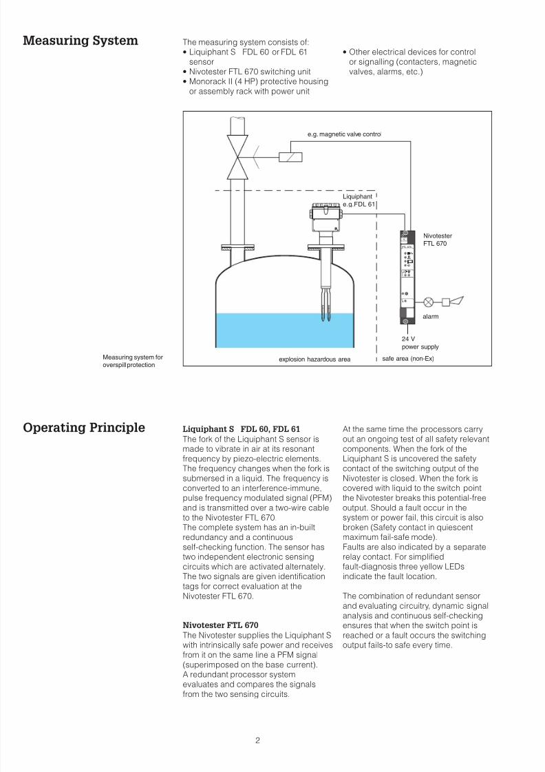
Measuring System The measuring system consists of:· Liquiphant S FDL 60 or FDL 61
sensor· Nivotester FTL 670 switching unit· Monorack II (4 HP) protective housing
or assembly rack with power unit
· Other electrical devices for controlor signalling (contacters, magneticvalves, alarms, etc.)
Operating Principle Liquiphant S FDL 60, FDL 61
The fork of the Liquiphant S sensor ismade to vibrate in air at its resonantfrequency by piezo-electric elements.The frequency changes when the fork issubmersed in a liquid. The frequency isconverted to an interference-immune,pulse frequency modulated signal (PFM)and is transmitted over a two-wire cableto the Nivotester FTL 670.The complete system has an in-built
redundancy and a continuousself-checking function. The sensor hastwo independent electronic sensingcircuits which are activated alternately.The two signals are given identificationtags for correct evaluation at theNivotester FTL 670.
Nivotester FTL 670
The Nivotester supplies the Liquiphant Swith intrinsically safe power and receivesfrom it on the same line a PFM signal(superimposed on the base current).
A redundant processor systemevaluates and compares the signalsfrom the two sensing circuits.
At the same time the processors carryout an ongoing test of all safety relevantcomponents. When the fork of theLiquiphant S is uncovered the safetycontact of the switching output of theNivotester is closed. When the fork iscovered with liquid to the switch pointthe Nivotester breaks this potential-freeoutput. Should a fault occur in thesystem or power fail, this circuit is alsobroken (Safety contact in quiescent
maximum fail-safe mode).Faults are also indicated by a separaterelay contact. For simplifiedfault-diagnosis three yellow LEDsindicate the fault location.
The combination of redundant sensorand evaluating circuitry, dynamic signalanalysis and continuous self-checkingensures that when the switch point isreached or a fault occurs the switchingoutput fails-to safe every time.
2
FTL 670
s
Measuring system for
overspill protection
e.g. magnetic valve control
Liquiphant
e.g.FDL 61
Nivotester
FTL 670
alarm
24 V
power supply
explosion hazardous area safe area (non-Ex)
8/6/2019 Ti 223 Fen
http://slidepdf.com/reader/full/ti-223-fen 3/12
Standards andRegulations
All local (national) standards and
regulations must be complied with inregard to overspill protection and
explosion protection as well as allrequirements given in the certificates.
3
FTL 670
s
z 26z 26
d 26d 26
d 18d 18
b 28b 28
b 20b 20
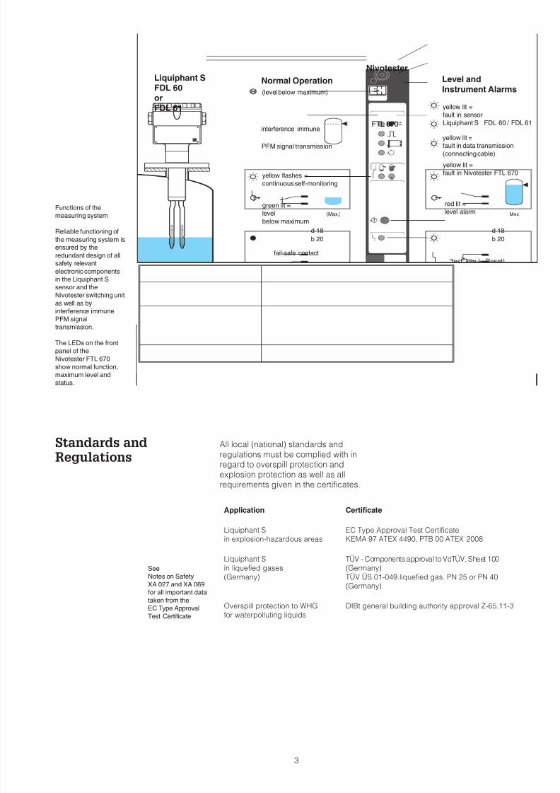
Max.(Max.)Functions of the
measuring system
Reliable functioning of
the measuring system is
ensured by the
redundant design of all
safety relevant
electronic components
in the Liquiphant Ssensor and the
Nivotester switching unit
as well as by
interference immune
PFM signal
transmission.
The LEDs on the front
panel of the
Nivotester FTL 670
show normal function,
maximum level and
status.
Level andInstrument Alarms
Normal Operation
green lit =
level
below maximum
unlit =normal operation
red lit =
level alarm
yellow lit =
fault in sensor
Liquiphant S FDL 60 / FDL 61
yellow lit =
fault in Nivotester FTL 670
fail-safe contact
yellow flashes =
continuous self-monitoring
yellow lit =fault in data transmission
(connecting cable)
red lit =fault alarm
“test” key (= Reset)
interference immune
PFM signal transmission
(level below maximum)
NivotesterLiquiphant SFDL 60orFDL 61
Application Certificate
Liquiphant Sin explosion-hazardous areas
EC Type Approval Test CertificateKEMA 97 ATEX 4490, PTB 00 ATEX 2008
Liquiphant S
in liquefied gases
(Germany)
TÜV - Components approval toVdTÜV, Sheet 100
(Germany)
TÜV ÜS.01-049.liquefied gas. PN 25 or PN 40(Germany)
Overspill protection to WHG
for waterpolluting liquids
DIBt general building authority approval Z-65.11-3
See
Notes on Safety
XA 027 and XA 069
for all important data
taken from the
EC Type Approval
Test Certificate
8/6/2019 Ti 223 Fen
http://slidepdf.com/reader/full/ti-223-fen 4/12
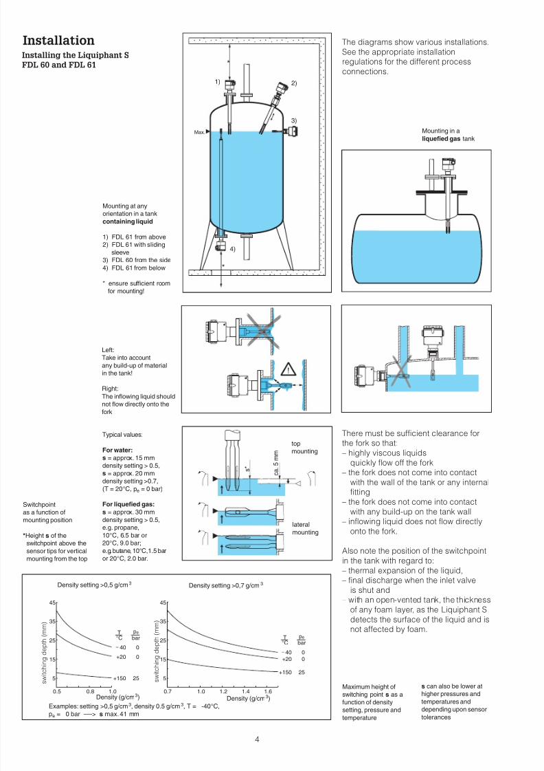
Installation The diagrams show various installations.
See the appropriate installationregulations for the different process
connections.
There must be sufficient clearance forthe fork so that:
– highly viscous liquids
quickly flow off the fork
– the fork does not come into contact
with the wall of the tank or any internalfitting
– the fork does not come into contact
with any build-up on the tank wall
– inflowing liquid does not flow directly
onto the fork.
Also note the position of the switchpoint
in the tank with regard to:
– thermal expansion of the liquid,
– final discharge when the inlet valve
is shut and
– with an open-vented tank, the thickness
of any foam layer, as the Liquiphant S
detects the surface of the liquid and isnot affected by foam.
4
Installing the Liquiphant S
FDL 60 and FDL 61
*
*
Max.
2)
3)
1)
4)
Mounting at any
orientation in a tank
containing liquid
1) FDL 61 from above
2) FDL 61 with sliding
sleeve
3) FDL 60 from the side
4) FDL 61 from below
* ensure sufficient room
for mounting!
Mounting in a
liquefied gas tank
s*
ca.5mm
Typical values:
For water:
s = approx. 15 mm
density setting > 0.5,
s = approx. 20 mm
density setting >0.7,
(T = 20°C, pe = 0 bar)
For liquefied gas:
s = approx. 30 mm
density setting > 0.5,
e.g. propane,
10°C, 6.5 bar or
20°C, 9.0 bar;
e.g.butane, 10°C,1.5 bar
or 20°C, 2.0 bar.
top
mounting
lateral
mounting
Left:
Take into account
any build-up of material
in the tank!
Right:
The inflowing liquid should
not flow directly onto thefork
Switchpoint
as a function of
mounting position
*Height s of the
switchpoint above the
sensor tips for vertical
mounting from the top
Maximum height of
switching point s as a
function of density
setting, pressure and
temperature
s can also be lower at
higher pressures and
temperatures and
depending upon sensor
tolerances
45 45
35 35
25 25
15 15
5 5
0.5 0.7 1.0 1.2 1.4 1.60.8 1.0
+20
+150
0
0
25
T°C
pbar
e
+20
+150
0
0
25
T°C
pbar
e
4040
Examples: setting >0,5 g/cm3, density 0.5 g/cm3, T = -40°C,
pe = 0 bar —-> s max.41 mm
Density setting >0,5 g/cm3 Density setting >0,7 g/cm3
Density (g/cm3) Density (g/cm3)
s w i t c h i n g d e p t h ( m m )
s w i t c h i n g d e p t h ( m m )
8/6/2019 Ti 223 Fen
http://slidepdf.com/reader/full/ti-223-fen 5/12
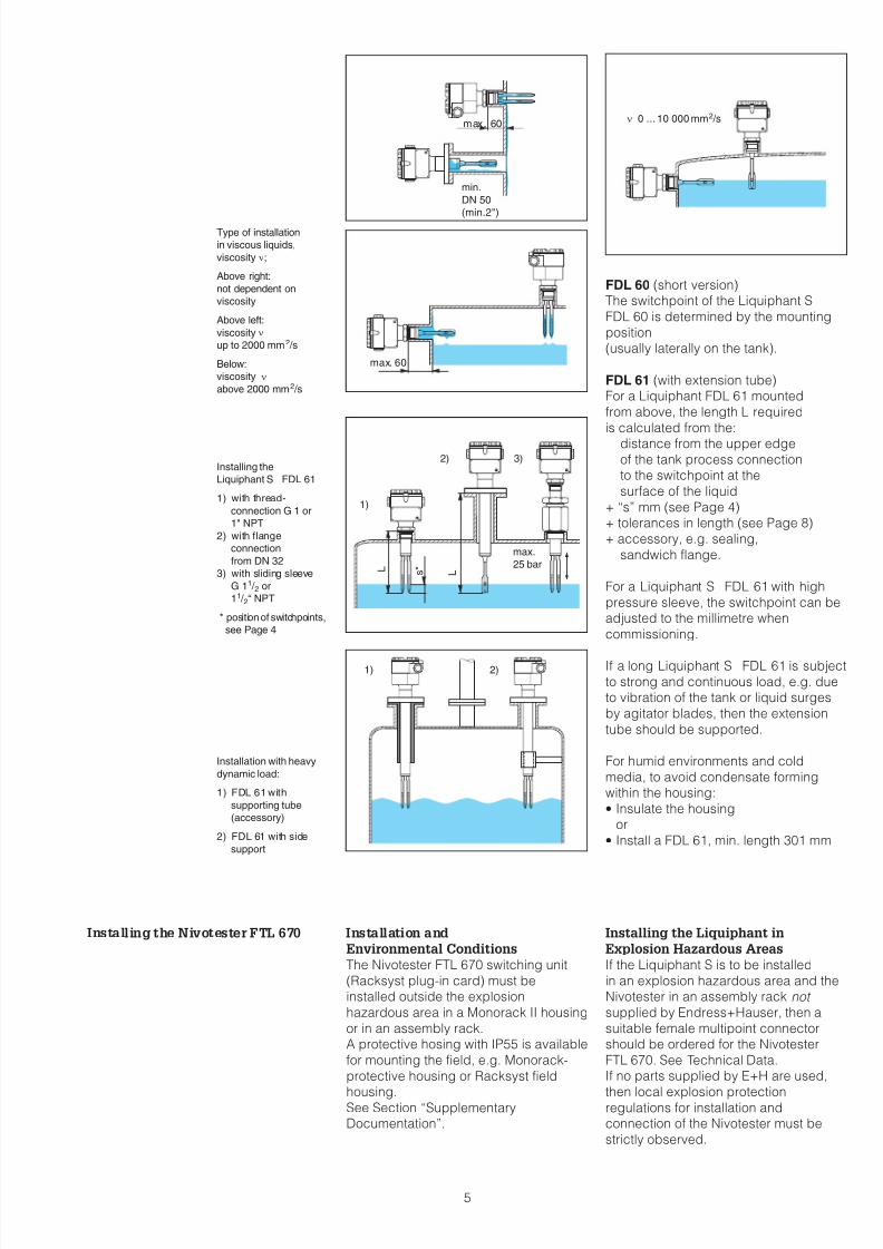
FDL 60 (short version)The switchpoint of the Liquiphant S
FDL 60 is determined by the mounting
position(usually laterally on the tank).
FDL 61 (with extension tube)For a Liquiphant FDL 61 mounted
from above, the length L required
is calculated from the:distance from the upper edge
of the tank process connectionto the switchpoint at the
surface of the liquid
+ “s” mm (see Page 4)+ tolerances in length (see Page 8)
+ accessory, e.g. sealing,
sandwich flange.
For a Liquiphant S FDL 61 with high
pressure sleeve, the switchpoint can beadjusted to the millimetre when
commissioning.
If a long Liquiphant S FDL 61 is subject
to strong and continuous load, e.g. dueto vibration of the tank or liquid surges
by agitator blades, then the extension
tube should be supported.
For humid environments and cold
media, to avoid condensate formingwithin the housing:· Insulate the housing
or· Install a FDL 61, min. length 301 mm
Installing the Nivotester FTL 670 Installation and
Environmental Conditions
The Nivotester FTL 670 switching unit
(Racksyst plug-in card) must beinstalled outside the explosion
hazardous area in a Monorack II housing
or in an assembly rack.A protective hosing with IP55 is available
for mounting the field, e.g. Monorack-
protective housing or Racksyst field
housing.See Section “SupplementaryDocumentation”.
Installing the Liquiphant in
Explosion Hazardous Areas
If the Liquiphant S is to be installed
in an explosion hazardous area and theNivotester in an assembly rack not supplied by Endress+Hauser, then a
suitable female multipoint connectorshould be ordered for the Nivotester
FTL 670. See Technical Data.If no parts supplied by E+H are used,
then local explosion protectionregulations for installation andconnection of the Nivotester must be
strictly observed.
5
n 0 ... 10 000 mm2 /s
Installing the
Liquiphant S FDL 61
1) with thread-
connection G 1 or
1" NPT
2) with flange
connection
from DN 32
3) with sliding sleeve
G 11 / 2 or
11 / 2“ NPT
* position of switchpoints,
see Page 4
1)
2) 3)
max.
25 bar L
L s *
Installation with heavy
dynamic load:
1) FDL 61 with
supporting tube
(accessory)
2) FDL 61 with side
support
1) 2)
Type of installation
in viscous liquids,
viscosity n;
Above right:
not dependent on
viscosity
Above left:
viscosity n
up to 2000 mm2 /s
Below:
viscosity n
above 2000 mm2 /s
max. 60
min.
DN 50
(min.2")
max. 60
8/6/2019 Ti 223 Fen
http://slidepdf.com/reader/full/ti-223-fen 6/12
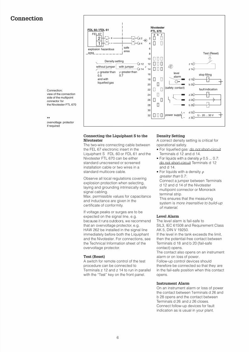
Connection
Connecting the Liquiphant S to the
Nivotester
The two-wire connecting cable betweenthe FEL 67 electronic insert in the
Liquiphant S FDL 60 or FDL 61 and the
Nivotester FTL 670 can be eitherstandard unscreened or screened
installation cable or two wires in astandard multicore cable.
Observe all local regulations covering
explosion protection when selecting,laying and grounding intrinsically safe
signal cabling.
Max. permissible values for capacitanceand inductance are given in the
certificate of conformity.
If voltage peaks or surges are to be
expected on the signal line, e.g.
because it runs outdoors, we recommendthat an overvoltage protector, e.g.
HAW 262 be installed in the signal lineimmediately before both the Liquiphant
and the Nivotester. For connections, see
the Technical Information sheet of the
overvoltage protector.
Test (Reset)
A switch for remote control of the testprocedure can be connected to
Terminals z 12 and z 14 to run in parallel
with the “Test” key on the front panel.
Density Setting
A correct density setting is critical for
operational safety.· For liquefied gas: do not short-circuit
Terminals d 12 and d 14.· For liquids with a density r 0.5 ... 0.7:
do not short-circuit Terminals d 12
and d 14.· For liquids with a density r
greater than 0.7:
Connect a jumper between Terminals
d 12 and d 14 of the Nivotestermultipoint connector or Monorack
terminal strip.This ensures that the measuring
system is more insensitive to build-up
of material .
Level Alarm
The level alarm is fail-safe to
SIL3, IEC 61508 and Requirement ClassAK 5, DIN V 19250.
If the level in the tank exceeds the limit,then the potential-free contact between
Terminals d 18 and b 20 (fail-safe
contact) opens.The contact also opens on an instrument
alarm or on loss of power.
Follow-up control devices shouldtherefore be connected so that they are
in the fail-safe position when this contact
opens.
Instrument Alarm
On an instrument alarm or loss of power
the contact between Terminals d 26 andb 28 opens and the contact between
Terminals d 26 and z 26 closes.Connect follow-up devices for fault
indication as is usual in your plant.
6
T
2d 2
4d 4
6
8
10
12 z 12d 12
14 z 14d 14
16
18 d 18
d 32L +
z 26
b 28
20 b 20
z 32
d 26
22
24
26
28
30
32
r
12
U _ 20 ... 30 V
*
*
*
*
Connection;
view of the connection
side of the multipoint
connector for
the Nivotester FTL 670
**
overvoltage protectorif required
r greater than
0.7
Density setting
without jumper with jumper
r greater than
0.5
and with
liquefied gas
Test (Reset)
stop filling
fault indication
power supply
level
alarm
(safety contact)
safe
areaexplosion hazardous
area
FDL 60 / FDL 61
FEL 67
Nivotester
FTL 670
8/6/2019 Ti 223 Fen
http://slidepdf.com/reader/full/ti-223-fen 7/12
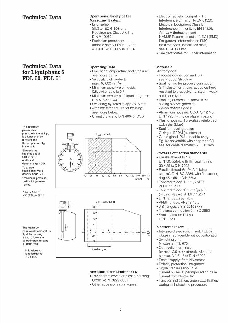
Technical Data Operational Safety of the
Measuring System
· Error safety:
SIL3 to IEC 61508 andRequirement Class AK 5 to
DIN V 19250· Explosion protection:
Intrinsic safety EEx ia IIC T6
ATEX II 1/2 G, EEx ia IIC T6
· Electromagnetic Compatibility:
Interference Emission to EN 61326;Electrical Equipment Class B
Interference Immunity to EN 61326;Annex A (Industrial) and
NAMUR Recommendation NE 21 (EMC)
For general information on EMC(test methods, installation hints)
see TI 241F/00/en· See certificates for further information
Technical Datafor Liquiphant SFDL 60, FDL 61
Operating Data
· Operating temperature and pressure:
see figure below· Viscosity n of product:
max. 10 000 mm2 /s· Minimum density r of liquid:
0.5, switchable to 0.7· Minimum density r of liquefied gas to
DIN 51622: 0.44· Switching hysteresis: approx. 5 mm· Ambient temperature for housing:
see figure below.· Climatic class to DIN 40040: GSD
Accessories for Liquiphant S
· Transparent cover for plastic housing:
Order No. 919229-0001· Other accessories on request.
Materials
Wetted parts:· Process connection and fork:
see Product Structure· Sealing ring for process connection
G 1: elastomer-thread, asbestos-free,resistant to oils, solvents, steam, weak
acids and lyes· Packing of pressure screw in the
sliding sleeve: graphite
External process parts:
· Aluminium housing: GD-Al Si 12 Mg,DIN 1725, with blue plastic coating
· Plastic housing: fibre-glass reinforcedpolyester (blue)
· Seal for housing cover:
O-ring in EPDM (elastomer)· Cable gland IP66 for cable entry
Pg 16: polyamide with neoprene CR
seal for cable diameters 7 ... 12 mm
Process Connection Standards
· Parallel thread G 1 A:
DIN ISO 228/I, with flat sealing ring33 x 39 to DIN 7603
· Parallel thread G 11 /2 A (slidingsleeve): DIN ISO 228/I, with flat sealing
ring 48 x 55 to DIN 7603· Tapered thread 1 - 111 /2 NPT:
ANSI B 1.20.1· Tapered thread 11 /2 - 111 /2 NPT
(sliding sleeve): ANSI B 1.20.1· DIN flanges: see table· ANSI flanges: ANSI B 16.5· JIS flanges: JIS B 2210 (RF)· Triclamp connection 2": ISO 2852· Sanitary thread DN 50:
DIN 11851
Electronic Insert· Integrated electronic insert: FEL 67,
plug-in, replaceable without calibration· Switching unit:
Nivotester FTL 670· Connection terminals:
for max. 2.5 mm2 strands with end
sleeves A 2.5 - 7 to DIN 46228· Power supply: from Nivotester· Polarity protection: integrated· Signal transmission: PFM;
current pulses superimposed on base
current from Nivotester· Function indication: green LED flashes
during self-checking procedure
7
30
10
40
20
25
200-20-40 100 120 140 1608060 T2
°C
pe
bar40
T2
pe
The maximum
permissible
pressure in the tank pe
is a function of the
medium and
the temperature T2
in the tank
Shaded area:
liquefied gas to
DIN 51622
and liquid
density range > 0.5
Total area:
liquids of all typesdensity range > 0.7
* maximum pressure
with sliding sleeve:
25 bar
in tank
in tank
*
T1
T2
T2
°C
80
60
40
40
20
200
-20
-20
-40
-40 100 120 140 1608060
**
T1
°C
The maximum
permissible temperature
T1 at the housing
is a function of the
operating temperature
T2 in the tank
* limit values for
liquefied gas to
DIN 51622
at housing
liquefied gas
1 bar = 14.5 psi
x°C (1.8 x + 32)°F
8/6/2019 Ti 223 Fen
http://slidepdf.com/reader/full/ti-223-fen 8/12
8
115
115
140
140
140
140
140
140
130
(135)
220...6000
220...6000
220...6000
220...6000
130
(135)
(135)
(135)
130
130
19
19
28
ø 29
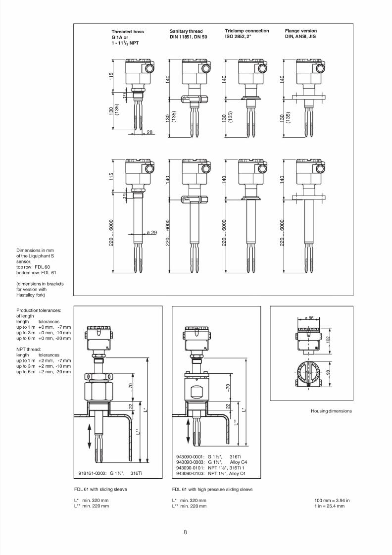
Dimensions in mm
of the Liquiphant S
sensor;
top row: FDL 60
bottom row: FDL 61
(dimensions in brackets
for version withHastelloy fork)
Threaded boss
G 1A or
1 - 111 / 2 NPT
Sanitary thread
DIN 11851, DN 50
Triclamp connection
ISO 2852, 2"
Flange version
DIN, ANSI, JIS
Production tolerances:
of length
length tolerances
up to 1 m +0 mm, -7 mm
up to 3 m +0 mm, -10 mm
up to 6 m +0 mm, -20 mm
NPT thread:
length tolerances
up to 1 m +2 mm, -7 mm
up to 3 m +2 mm, -10 mm
up to 6 m +2 mm, -20 mm
100 mm = 3.94 in
1 in = 25.4 mm
2 2
L * *
L *
~
7 0
918161-0000: G 1½", 316Ti
FDL 61 with sliding sleeve
L* min. 320 mm
L** min. 220 mm
ø 86
~
1 0 2
~
9 8
Housing dimensions
L * *
L *
~ 7 0
2 2
943090-0001: G 1½", 316Ti943090-0003: G 1½", Alloy C4943090-010 11: NPT 1½", 316Ti
943090-0103: NPT 1½", Alloy C4
FDL 61 with high pressure sliding sleeve
L* min. 320 mm
L** min. 220 mm
8/6/2019 Ti 223 Fen
http://slidepdf.com/reader/full/ti-223-fen 9/12
9
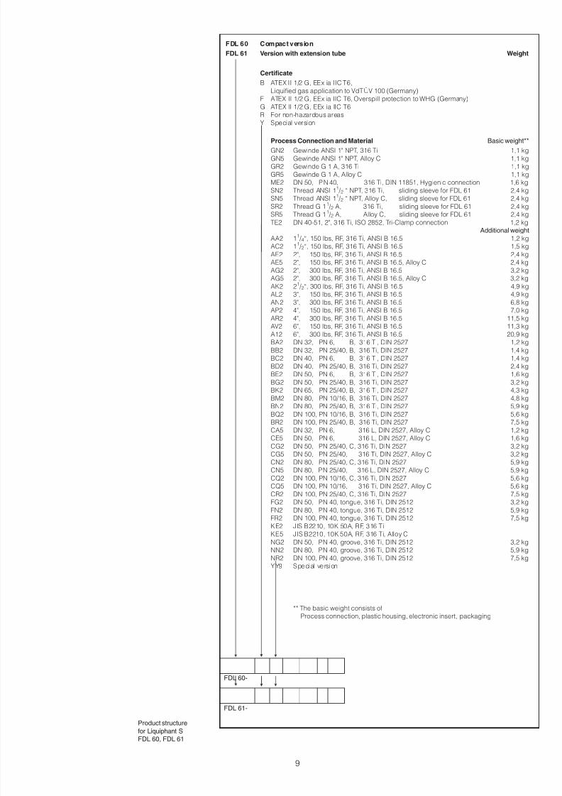
FDL 60 Compact version
FDL 61 Version with extension tube Weight
Certificate
B ATEX II 1/2 G, EEx ia IIC T6,
Liquified gas application to VdTÜV 100 (Germany)
F ATEX II 1/2 G, EEx ia IIC T6, Overspill protection to WHG (Germany)
G ATEX II 1/2 G, EEx ia IIC T6
R For non-hazardous areas
Y Special version
Process Connection and Material Basic weight**
GN2 Gewinde ANSI 1" NPT, 316 Ti 1,1 kg
GN5 Gewinde ANSI 1" NPT, Alloy C 1,1 kg
GR2 Gewinde G 1 A, 316 Ti 1,1 kg
GR5 Gewinde G 1 A, Alloy C 1,1 kg
ME2 DN 50, PN 40, 316 Ti, DIN 11851, Hygienic connection 1,6 kg
SN2 Thread ANSI 11 /2 “ NPT, 316 Ti, sliding sleeve for FDL 61 2,4 kg
SN5 Thread ANSI 11 /2 “ NPT, Alloy C, sliding sleeve for FDL 61 2,4 kg
SR2 Thread G 11 /2 A, 316 Ti, sliding sleeve for FDL 61 2,4 kg
SR5 Thread G 11 /2 A, Alloy C, sliding sleeve for FDL 61 2,4 kg
TE2 DN 40-51, 2", 316 Ti, ISO 2852, Tri-Clamp connection 1,2 kgAdditional weight
AA2 11 /4“, 150 lbs, RF, 316 Ti, ANSI B 16.5 1,2 kg
AC2 11 /2“, 150 lbs, RF, 316 Ti, ANSI B 16.5 1,5 kg
AE2 2", 150 lbs, RF, 316 Ti, ANSI B 16.5 2,4 kg
AE5 2", 150 lbs, RF, 316 Ti, ANSI B 16.5, Alloy C 2,4 kg
AG2 2", 300 lbs, RF, 316 Ti, ANSI B 16.5 3,2 kg
AG5 2", 300 lbs, RF, 316 Ti, ANSI B 16.5, Alloy C 3,2 kgAK2 21 /2“, 300 lbs, RF, 316 Ti, ANSI B 16.5 4,9 kg
AL2 3", 150 lbs, RF, 316 Ti, ANSI B 16.5 4,9 kg
AN2 3", 300 lbs, RF, 316 Ti, ANSI B 16.5 6,8 kg
AP2 4", 150 lbs, RF, 316 Ti, ANSI B 16.5 7,0 kg
AR2 4", 300 lbs, RF, 316 Ti, ANSI B 16.5 11,5 kg
AV2 6", 150 lbs, RF, 316 Ti, ANSI B 16.5 11,3 kg
A12 6", 300 lbs, RF, 316 Ti, ANSI B 16.5 20,9 kg
BA2 DN 32, PN 6, B, 316 Ti, DIN 2527 1,2 kg
BB2 DN 32, PN 25/40, B, 316 Ti, DIN 2527 1,4 kg
BC2 DN 40, PN 6, B, 316 Ti, DIN 2527 1,4 kg
BD2 DN 40, PN 25/40, B, 316 Ti, DIN 2527 2,4 kg
BE2 DN 50, PN 6, B, 316 Ti, DIN 2527 1,6 kg
BG2 DN 50, PN 25/40, B, 316 Ti, DIN 2527 3,2 kg
BK2 DN 65, PN 25/40, B, 316 Ti, DIN 2527 4,3 kg
BM2 DN 80, PN 10/16, B, 316 Ti, DIN 2527 4,8 kg
BN2 DN 80, PN 25/40, B, 316 Ti, DIN 2527 5,9 kg
BQ2 DN 100, PN 10/16, B, 316 Ti, DIN 2527 5,6 kg
BR2 DN 100, PN 25/40, B, 316 Ti, DIN 2527 7,5 kg
CA5 DN 32, PN 6, 316 L, DIN 2527, Alloy C 1,2 kg
CE5 DN 50, PN 6, 316 L, DIN 2527, Alloy C 1,6 kg
CG2 DN 50, PN 25/40, C, 316 Ti, DIN 2527 3,2 kg
CG5 DN 50, PN 25/40, 316 Ti, DIN 2527, Alloy C 3,2 kg
CN2 DN 80, PN 25/40, C, 316 Ti, DIN 2527 5,9 kg
CN5 DN 80, PN 25/40, 316 L, DIN 2527, Alloy C 5,9 kg
CQ2 DN 100, PN 10/16, C, 316 Ti, DIN 2527 5,6 kg
CQ5 DN 100, PN 10/16, 316 Ti, DIN 2527, Alloy C 5,6 kg
CR2 DN 100, PN 25/40, C, 316 Ti, DIN 2527 7,5 kg
FG2 DN 50, PN 40, tongue, 316 Ti, DIN 2512 3,2 kg
FN2 DN 80, PN 40, tongue, 316 Ti, DIN 2512 5,9 kg
FR2 DN 100, PN 40, tongue, 316 Ti, DIN 2512 7,5 kg
KE2 JIS B2210, 10K 50A, RF, 316 Ti
KE5 JIS B2210, 10K 50A, RF, 316 Ti, Alloy C
NG2 DN 50, PN 40, groove, 316 Ti, DIN 2512 3,2 kg
NN2 DN 80, PN 40, groove, 316 Ti, DIN 2512 5,9 kg
NR2 DN 100, PN 40, groove, 316 Ti, DIN 2512 7,5 kgYY9 Special version
** The basic weight consists of
Process connection, plastic housing, electronic insert, packaging
Product structure
for Liquiphant S
FDL 60, FDL 61
FDL 60-
FDL 61-
8/6/2019 Ti 223 Fen
http://slidepdf.com/reader/full/ti-223-fen 10/12
10
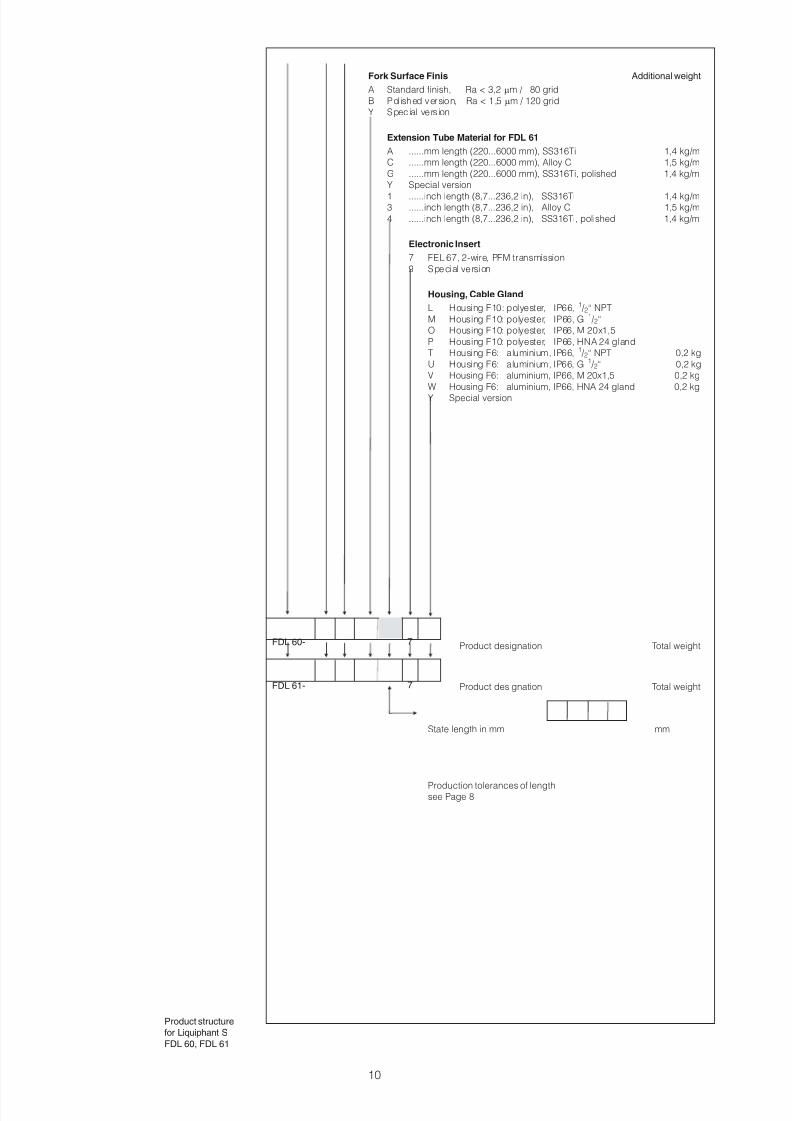
Fork Surface Finis Additional weight
A Standard finish, Ra < 3,2 mm / 80 grid
B Pol ished version, Ra < 1,5 mm / 120 grid
Y Special version
Extension Tube Material for FDL 61
A ......mm length (220...6000 mm), SS316Ti 1,4 kg/m
C ......mm length (220...6000 mm), Alloy C 1,5 kg/m
G ......mm length (220...6000 mm), SS316Ti, polished 1,4 kg/m
Y Special version
1 ......inch length (8,7...236,2 in), SS316Ti 1,4 kg/m3 ......inch length (8,7...236,2 in), Alloy C 1,5 kg/m
4 ......inch length (8,7...236,2 in), SS316Ti, polished 1,4 kg/m
Electronic Insert
7 FEL 67, 2-wire, PFM transmission
9 Special version
Housing, Cable Gland
L Housing F10: polyester, IP66, 1 /2“ NPT
M Housing F10: polyester, IP66, G 1 /2“O Housing F10: polyester, IP66, M 20x1,5
P Housing F10: polyester, IP66, HNA 24 gland
T Housing F6: aluminium, IP66, 1 /2“ NPT 0,2 kg
U Housing F6: aluminium, IP66, G 1 /2“ 0,2 kg
V Housing F6: aluminium, IP66, M 20x1,5 0,2 kg
W Housing F6: aluminium, IP66, HNA 24 gland 0,2 kg
Y Special version
Product designation Total weight
Product designation Total weight
State length in mm mm
Production tolerances of lengthsee Page 8
Product structure
for Liquiphant S
FDL 60, FDL 61
FDL 60-
FDL 61-
7
7
8/6/2019 Ti 223 Fen
http://slidepdf.com/reader/full/ti-223-fen 11/12
Technical Datafor Nivotester FTL 670
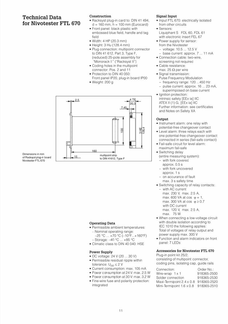
Construction
· Racksyst plug-in card to: DIN 41 494,d = 160 mm, h = 100 mm (Eurocard)
· Front panel: black plastic withembossed blue field, handle and tag
field· Width: 4 HP (20.3 mm)· Height: 3 Hu (128.4 mm)· Plug connection: multipoint connector
to DIN 41 612, Part 3, Type F,
(reduced) 25-pole assembly for“Monorack II” (“Racksyst II”)
· Coding holes in the multipointconnector: Pos. 2 and 11
· Protection to DIN 40 050:Front panel IP20, plug-in board IP00
· Weight: 200 g
Operating Data
· Permissible ambient temperatures:– Nominal operating range:
–25 °C ... +70 °C (–10°F...+160°F)
– Storage: –40 °C ... +85 °C· Climatic class to DIN 40 040: HSE
Power Supply
· DC voltage: 24 V (20 ... 30 V)· Permissible residual ripple within
tolerance: Upp £ 2 V· Current consumption: max. 105 mA· Power consumption at 24 V: max. 2.5 W· Power consumption at 30 V: max. 3.2 W· Fine-wire fuse and polarity protection:
integrated
Signal Input
· Input FTL 670: electrically isolatedfrom other circuits
· Sensors:Liquiphant S FDL 60, FDL 61
with electronic insert FEL 67· Power supply for sensor:
from the Nivotester
– voltage: 10.5 ... 12.5 V
– base current: approx. 7 ... 11 mA· Connection cable: two-wire,
screening not required· Cable resistance:
max. 25 W per wire· Signal transmission:
Pulse Frequency Modulation
– frequency range: 120 ...450 Hz
– pulse current: approx. 16 ... 23 mA,superimposed on base current
· Ignition protection:
intrinsic safety [EEx ia] IICATEX II (1) G, [EEx ia] IIC
Further information: see certificatesand Notes on Safety XA
Output
· Instrument alarm: one relay with
potential-free changeover contact· Level alarm: three relays each with
one potential-free changeover contactconnected in series (fail-safe contact)
· Fail-safe circuit for level alarm:
maximum fail-safe· Switching delay
(entire measuring system):
– with fork coveredapprox. 0.5 s
– with fork uncoveredapprox. 1 s
– on accurance of fault
max. 3 s safety time· Switching capacity of relay contacts:
– with AC current
max. 230 V, max. 2.5 A,max. 600 VA at cos j = 1,
max. 300 VA at cos j ³ 0.7
– with DC currentmax. 120 V, max. 2.5 A,
max. 75 W· When connecting a low-voltage circuit
with double isolation according to
IEC 1010 the following applies:Total of voltages of relay output and
power supply max. 300 V· Function and alarm indicators on front
panel: 7 LEDs
Accessories for Nivotester FTL 670
Plug-in point kit 25/2,consisting of multipoint connector,
coding pins, isolating cap, guide rails
Connection: Order No.:
Wire-wrap 1 x 1 918365-2500
Solder connection 918365-2530Maxi-Termipoint 2.4 x 0.8 918365-2520
Mini-Termipoint 1.6 x 0.8 918365-2510
11
2,5
15
160
4 TE
20,3
7,45
100
3HE
128,4
Dimensions in mm
of Racksyst plug-in board
Nivotester FTL 670
multipoint strip
to DIN 41612, Type F
8/6/2019 Ti 223 Fen
http://slidepdf.com/reader/full/ti-223-fen 12/12
Order Specifications Liquiphant S FDL 60, FDL 61
· Product designation based onstructure, page 9/10
· Length for FDL 61 in mm· Accessories
Nivotester FTL 670
· Order No. 016501-0040· Accessories
SupplementaryDocumentation
Accessories
Monorack IITechnical Information TI 183F/00/en
Monorack Protective HousingTechnical Information TI 099F/00/en
19" Assembly Rack System-Information Racksyst
SI 008F/00/en
Project Information SD 041F/00/en
Racksyst Field Housing
Technical Information PI 026Project Information PI 003
Overvoltage Protector HAW 262Technical Information TI 108F/00/en
Overvoltage Protector HAW 262 ZFor explosion hazardous areas
Technical Information TI 092F/00/de
Other accessories on request
TI 223F/00/en/04.04
CCS/CV8
Certificates
Notes on Safety to ATEX(KEMA 97 ATEX 4490)
for Liquiphant S FDL 60, FDL 61
Operating Instructions XA027F/00/a3
Notes on Safety to ATEX
(PTB 00 ATEX 2008)for Nivotester FTL 670
Operating Instructions XA069F/00/a3
Special German Certificates on request
05.02/PT1
Endress+Hauser
GmbH+Co. KG
Instruments
International
P.O. Box 2222
D-79574 Weil am Rhein
Germany
Tel. (076 21) 975-02
Fax (07621) 975-345
http://www.endress.com
Hauser+EndressThe Power of Know How