THX120-CCP - vetusmarine.americommerce.com PDFs/THX… · THX120-CCP Thru-Hull ... should the light...
13
Colour-CHANGE Lights THX120-CCP Thru-Hull Installation and Operation Guide THX120-CCP
-
Upload
phamnguyet -
Category
Documents
-
view
212 -
download
0
Transcript of THX120-CCP - vetusmarine.americommerce.com PDFs/THX… · THX120-CCP Thru-Hull ... should the light...
Colour-CHANGE Lights
THX120-CCP Thru-Hull
Installation and Operation Guide
THX120-CCP

Page 2
Congratulations! You have purchased a LUMISHORE advanced technology LED underwater light. Every care has been taken to ensure your Thru-Hull Colour Change
Plus light arrives in perfect condition, so please enjoy the ultimate experience in underwater lighting.
Please read the following pages before attempting installation to ensure complete understanding of the LUMISHORE LED lights.
LUMISHORE Thru-Hull Hi-Intensity LED lights are designed for those owners who prefer the integrity of a thru-hull installation using the most powerful, efficient, and
cost effective underwater LED lighting systems on the market today. Available in a variety of colour and power levels, the LUMISHORE Thru-Hull is suitable for many
sizes and types of watercraft, including Sports Boats, Cruisers, Yachts, and Super Yachts. LUMISHORE Thru-Hull LED lights come with a compact electronic driver
module to ensure trouble free operation for years to come.
LUMISHORE’s ColourChange system provides the customer with the ultimate choice of colour to match water conditions, attract fish with the Fishing Strobe modes,
or just set the right mood. Our proprietary HICOB technology optimizes the underwater viewing experience and gives the boat owner a choice of millions of
controllable colour options. The system comes with six preset colour (Blue, Cyan, White, Green, Magenta, and Red), four Fishing Strobe modes, personal colour
mixing, and colour cycling modes. The unit is also DMX-enabled for integration with sound systems.
FEATURES
• THX120-CCP Thru-Hull mount, requires 1" entry hole (transom mounting only)
• 6 preset colours: Blue. Cyan, White, Green, Magenta, and Red
• Colour mix, cycle, strobe, and music integration modes
• HICOB Array with an intensity of 8980 Fixture Lumens (White)
• 120 Watt HICOB LED array, equivalent to 600 Watt halogen lamp
• Lens: Toughened BK7 Borosilicate, 90° beam angle
• Marine-grade aluminium bronze housings
• Over-voltage/current, reverse polarity, and thermal rollback protection
PACKING LIST
If any of the following items are missing, email or call LUMISHORE using the information in provided in Product Support section.
Two THX120-CCP Colour Change lights with Driver Modules, Colour Controller, Junction box, terminal strip, Installation and Operation Guide
ACCESSORIES
ISS-120: Delrin Plastic Isolation Sleeve
THX-CCP-WIFI: Wireless DMX iPad or iPhone interface
TABLE OF CONTENTS
Number Section Page
1.0 BEFORE YOU START 3
2.0 THX120-CCP THRU-HULL LIGHTS 3
2.1 Materials and Dimensions 3
3.0 LIGHT INSTALLATION 4
4.0 OPTIONAL DELRIN ISOLATION SLEEVE 5
5.0 CONTROLLER INSTALLATION 6
6.0 DRIVER INSTALLATION 7
7.0 ELECTRICAL CONNECTIONS 7
7.1 Junction box 7
7.2 Cable Size (gauge) 8
7.3 Connection example 9
8.0 CONTROLLER OPERATION 10
8.1 Keys 10
8.2 Operation (Colour-SELECT, Colour-CYCLE, Fishing Strobe and Colour-MIX 10
9.0 MAINTENANCE 11
10.0 PRODUCT SUPPORT INQUIRIES 11
11.0 SPECIFICATIONS 11
12.0 TROUBLESHOOTING 11
Notes 12

Page 3
1.0 BEFORE YOU START
High Intensity LED light – Do not stare into the led module at close proximity.
Always ensure that the vessel’s power source and battery are disconnected or isolated prior to installation.
Both electrical and mechanical installation should be carried out by a qualified professional, to ensure installation with the utmost care and caution. If in
doubt please contact LUMISHORE. Refer to Product Support Section
The Driver supplies voltage and current to the Thru-Hull lights. Under no circumstances should the light cable be cut and connected directly to voltage.
Always use a suitable fuse or circuit breaker to protect the complete system.
The LUMISHORE Thru-hull light is only designed to be operated underwater. If the light is operated out of water for more than 5 minutes it will become
hot and switch itself off.
The LUMISHORE Thru-Hull may be installed into GRP (Glass Reinforced Plastic, Fiberglas) and wooden Hulls. To mount in an aluminium or steel hull the
light will need to be used with the optional Delrin Plastic Isolation Sleeve.
The light should be 6”- 10” (150-250mm) below the surface line of the water.
For Best results install the lights between 2.6 Feet (0.8m) and 6.5 Feet (2m) apart.
Never try to install or remove the light module with the vessel in the water.
All LUMISHORE products should have the appropriate bonding strap and electronic protection.
Do not over tighten the Retaining Bolts. A force of 3nM on each bolt should not be exceeded.
The Thru-Hull electronics have been fitted with an over-temperature cut off feature. Three flashes of the light output indicates an over-temp condition.
The unit will continue to flash until the light has returned to a safe operating temperature.
Lights should not be exposed to any temperatures in excess of 150°F (65°C). For example, next to hot engine components or where exhaust emissions
could be expelled onto the light while underway.
Note: Before mounting the Drivers and Lights, record the serial for future reference. The serial number is located on the light cable and on the rear of the driver.
2.0 THX120-CCP LIGHTS
Bonding Attention: LUIMISHORE lights should be bonded to the vessel’s DC bonding system to ensure protection from electrolytic/galvanic corrosion. All bonding
connections should be fully checked prior to returning the vessel to the water. LUMISHORE lights have integrated circuitry to protect lights from external issues, but
these are dependent upon the correct bonding. Failure to bond the lights properly and maintain the appropriate protection will invalidate the LUMISHORE
warranty.
Location – positioning will be dependent on both external and internal obstacles; consideration should also be given to installation wiring and internal access within the vessel. Ideally the light modules should be installed 6” to 10” (150-250mm) below the surface water line and spaced between 2.6 to 6.5Feet (0.8-2meters) apart.
Select a flat surface; make sure that both the internal and external surface of the hull are even and parallel. It may be necessary to sand or grind the surface.
A hole will be drilled to allow the cable to be inserted; care must be taken to ensure there is unrestricted access inside the hull.
The light is temperature sensitive and must not be located close to the exhaust
If multiple lights are installed, each light should be evenly spaced to ensure the best water illumination.
The number of lights and the spacing on your vessel will depend on a few factors: vessel size, location of lights, and water clarity.
2.1 Materials and Dimensions:
Required 1” (25mm) hole saw, 3M 4200 sealant (or equivalent) , 5mm Allen wrench, bonding strap and connections, and rag(s) for cleanup
Note: The cable must remain intact (do not cut/splice).
Supplied with 3 meters (9Feet) of cable
Dimensions
Sealant and Bonding

Page 4
3.0 LIGHT INSTALLATION
1. Double check for internal obstacles before drilling a 1 inch (26mm) perpendicular hole through the hull. 2. The exposed inner hull surface must be properly sealed to prevent water intrusion into the hull before the light module is secured in place. 3. Before inserting the light, ensure that the hull surface is free from dirt and grease; remove any existing anti-foul from the hull surface.
Note: Do not use an alcohol-based solvent as this may have an adverse effect on the sealant.
4. Using an approved adhesive (3M 4200 Marine or similar), apply liberally a continuous bead of sealant around the entire circumference of the sealant groove, on the base of the stem, and on the shaft of the light.
5. Carefully feed the control cable through the 1 inch (26mm) hole. Care must be taken to avoid getting sealant onto the connector and internal pins. 6. Gently insert the stem of the Light Module through the hole in the hull. 7. Apply gentle, even pressure with a slight circular motion until the Light module is flush with the hull surface.
!! IMPORTANT: Ensure that each light module has correct vertical and horizontal alignment with the hull. Ensure the LUMISHORE logo within the light module is at the top.
8. From inside the vessel, feed the supplied washer down the shaft of the light module. Screw the locking nut in place and tighten the retaining bolts so that they
are hand tight. (less than 1nM) – Do not tighten fully at this stage, excess pressure will push all of the sealant out. 9. Remove excess sealant that is squeezed from behind the light. 10. Allow the sealant to cure according to the sealant manufacturer’s instructions. Once fully cured, use a 5mm Allen wrench to re-tighten each retaining bolt
(force less than 3nM). Care should be taken not to exceed this force as damage to the light module or hull of the vessel may occur. 11. Attach the vessel’s bonding protection to the bonding bolt on the Locking Nut.
!! IMPORTANT: Before launching the vessel the sealant should be checked to ensure it is fully cured in accordance with the manufacturer’s instructions.

Page 5
4.0 OPTIONAL DELRIN ISOLOATION SLEEVE
Assembly of the Isolation Sleeve should be carried out just prior to installation of the light to the vessel.
NB: the hole cut out required for the isolation sleeve is 1.3’ (32mm).
1. After drilling the 1.3” (32MM) hole, measure the thickness of the hull, ensure that the isolation shaft sleeve is less than the hull thickness. If the shaft sleeve is too long, cut to length using the radial grooves as a guide. (Refer to the assembly diagram above).
2. Before assembling the isolation sleeve, ensure that the light and sleeve surfaces are free from dirt and grease. Note: Do not use an alcohol-based solvent as this may have an adverse effect on the sealant.
3. Using an approved adhesive (3M 4200 Marine or similar), apply liberally a continuous bead of sealant around the entire circumference of the sealant groove, on the base of the stem, and on the shaft of the light.
4. Slide the isolation sleeve down the light’s shaft so that it sits firmly against the back of the light, push the sleeve onto the back of the light until the two surfaces are flush. At this point any excess sealant can be removed using a soft cloth and suitable cleaner.
5. Place the Delrin isolation washer sleeve over the aluminium bronze washer. 6. Using the isolation sleeve sealing rings for the marine adhesive, the light module is now ready to install onto the vessel. 7. During installation and from inside the vessel, apply sealant from the rear around the shaft to ensure that there is no potential contact
between the shaft and the hull.
Isolation washer sleeve
Light Module
Vessel Hull
Isolation sleeve should be less than Hull thickness – Use a
sharp knife to cut to length if required.
NB: Apply additional sealant between shaft and hull
Delrin Washer
Locking Nut and
Retaining Bolts
Delrin Isolation Sleeve Radial grooves
Light Module
Sealing Rings
Isolation Sleeve
Sealing Rings
Light’s Shaft
1.3” (32MM) hole

Page 6
5.0 CONTROLLER INSTALLATION
Note: ONE Controller maybe connected to up to fourteen lights. Controllers may not be wired in parallel for dual station operation.
INPUT VOLTAGE RANGE: 10.5-31VDC
Mode Typical Max Current Per Device
Colour Controller (Standby)
<0.05 Amps
Colour controller (All modes)
<0.10 Amps
RED WIRE: Positive Voltage BLACK WIRE: Negative Voltage YELLOW WIRE: Data Signal DMX Input Blue wire = DMX (-), White wire = DMX (+) Green wire = DMX Ground DMX512 is a standard for digital communication. LUMISHORE added this function to control lights via iPad or iPhone.
The Colour Controller has been designed with both Proud or Flush mount options and can
be mounted inside a cabin, outside within the cockpit, or on the dashboard of the vessel.
IMPORTANT: Ensure correct electrical cable polarity. Incorrect installation will invalidate warranty. · Select a suitable flat surface that is accessible from behind. · Determine whether the colour controller will be proud or flush mount. · For flush mount option remove (and save for future use) the spacer by unscrewing the three M2x20mm Spacer screws.
· Ensure there are no obstructions and there is adequate clearance behind the surface to allow for the Colour Controller cable entry and positioning. (Ensure the chosen position also has easy cable routing access to the IP66 Junction box that is provided)
· For external installations or where water may access the unit it is recommended that an appropriate marine sealant be used between the back of the Colour Controller and the surface.
Proud mount
1. Drill a 26mm (1 inch) hole through the mounting surface. 2. Feed the Colour Controller and cable through the hole. Using the locknut,
adjust until hand tight. (Do not exceed 1Nm torque force) Surface Mount
1. Drill a 76mm (3inch) hole through the mounting surface. 2. Feed the Colour Controller and cable through the hole, using the 25mm locknut
and mounting bracket for flush mount, adjust until hand tight. (Do not exceed 1Nm torque force)
Page 7
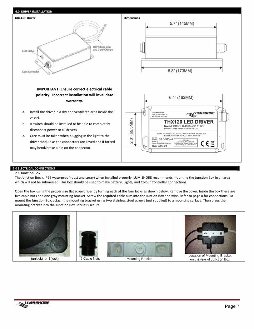
6.0 DRIVER INSTALLATION
UIX-CCP Driver
IMPORTANT: Ensure correct electrical cable
polarity. Incorrect installation will invalidate
warranty.
a. Install the driver in a dry and ventilated area inside the
vessel.
b. A switch should be installed to be able to completely
disconnect power to all drivers.
c. Care must be taken when plugging in the light to the
driver module as the connectors are keyed and if forced
may bend/brake a pin on the connector.
Dimensions
7.0 ELECTRICAL CONNECTIONS
7.1 Junction Box The Junction Box is IP66 waterproof (dust and spray) when installed properly. LUMISHORE recommends mounting the Junction Box in an area which will not be submersed. This box should be used to make battery, Lights, and Colour Controller connections. Open the box using the proper size flat screwdriver by turning each of the four locks as shown below. Remove the cover. Inside the box there are five cable nuts and one gray mounting bracket. Screw the required cable nuts into the Juntion Box and wire. Refer to page 8 for connections. To mount the Junction Box, attach the mounting bracket using two stainless steel screws (not supplied) to a mounting surface. Then press the mounting bracket into the Junction Box until it is secure.
-(unlock) or 1(lock)
5 Cable Nuts
Mounting Bracket
Location of Mounting Bracket on the rear of Junction Box

Page 8
7.2 Cable size (Gauge) LUMISHORE lights have advanced electronic systems which maintain the illumination output of the LEDs to protect them from under current or voltage.
Note: Current draw per module with a light connected: 12VDC – 7.5A / 24VDC – 3.75A
Proper wire cable size must be considered when installing the lights.
Compute the gauge of the cable needed at 12VDC or 24VDC.
Cable lengths referenced in the Conductor Size tables are from the source to the lights and back to the source.
Calculate the total current draw of all drivers that are connected to the terminal strip and use the chart below to find cable size from power source to
terminal strip. Use the same size wire from the terminal strip to each driver to extend the 3.5-foot cable attached to each driver.

Page 9
7.3 Connection Example

Page 10
8.0 CONTROLLER OPERATION
8.1 KEYS PWR – Standby Power
a. Press PWR once to turn the lights ON, PWR ON will momentarily be shown on the display. b. Press again turn lights OFF (Standby mode), PWR OFF will be momentarily shown on the display. Note: If the PWR key is pressed to enter standby mode or if power is switched off, the controller will remember its last function.
MODE – Mode Function Select
Each press this button cycles through 12 pre-programmed settings. The selected number and mode is displayed on the LCD screen.
MIX – When selected allows red, green and blue to be customized independently.
Note: If the PWR key is pressed to enter standby mode or if power is switched off at the source the Colour Controller will remember its last function state and revert back to this mode when power is resumed.
UP/DOWN – Used with MODE selections to adjust brightness, control colour change, and strobe repetition, plus change colours in MIX Mode.
8.2 OPERATION Colour-Select Mode
a. Press the MODE key to select a light colour (RED, GREEN, BLUE, MAGENTA, CYAN or WHITE) which is shown on the Colour Controller’s LCD display. Colour-Cycle Mode
a. Press the MODE key until the LCD screen on the Colour Controller shows CYCLE mode. b. Press the UP or DOWN key to increase or decrease how fast the lights change from one colour to another. 1 = fast (30 second cycle) to 10 = slow (60
minute) colour cycle. Fishing Strobe Mode (colours and repetition rate) This mode is used to attract fish. The Colour Controller has two colour selections (Green and Blue), 2 Strobe modes for each light colour, and 10 repetition rates.
a. Press the MODE key repeatedly until the display shows Fish Mode 1 (Green blinking), Fish Mode 2 (Green random blinking) / Fish Mode 3 (blue blinking) or Fish Mode 4 (Blue random blinking)
b. After the Fish Mode is shown, press the UP or DOWN key to increase or decrease the repetition rate of the strobe. 1 = fast, 10=slow strobe. c. To exit the Fish Strobe Mode, press the MODE key to select another function.
MIXING MODE
a. Press the MIX key repeatedly until the display shows Green, Blue, or Red. b. After the light colour is shown on the LCD, press the UP or DOWN key to increase or decrease the amount of colour to be mixed, (0 to 100%) from the
desired colour. c. To exit the Mixing Mode, press the MODE key to and select another function.

Page 11
9.0 MAINTENANCE
The locking nut and retaining bolts should be inspected on a regular basis to ensure they are kept tight. LUMISHORE recommends general
inspection of the light module, driver, and cable attachments every month.
The glass lens should be kept clean with a plastic scraper or soft brush. Regular cleaning of the lens will ensure that the Light module delivers
maximum optical output. Do not use an abrasive cloth or cleaning agent as permanent damage to the lens may occur.
To prolong device lifetime and prevent marine growth build up, a good quality antifouling system should be used to coat the external body of
the device. This should be renewed regularly. A transparent anti-foul should also be used on the lens surface.
10.0 PRODUCT SUPPORT INQUIRIES
If you have questions or comments, please email [email protected] or call:
USA call (941)405-3302, United Kingdom +44(0)208 144 1694, France +33(0)493 582 537.
11.0 SPECIFICATIONS
Specifications are subject to change without notice.
LUMISHORE Ltd warrants the Colour-Change to be free from defects in
workmanship and materials for a period of 2 years starting from the date
of original purchase.
Misuse, abuse, improper installation, neglect, improper shipping, damage
caused by disasters such as fire, flood and lightning, installation by
unqualified personnel, unauthorized repair or modification will void this
warranty.
For the avoidance of confusion and doubt, non-compliance with all
installation and maintenance instructions in this document constitute non-
conformance with warranty terms. Should your light be defective during
this period, please contact your dealer as soon as you become aware of
the defect.
Full warranty details are available at www.lumishore.com
12.0 WARRANTY INFORMATION
13.0 TROUBLESHOOTING
TROUBLESHOOTING DRIVER STATUS INDICATOR - The Driver module may have an External or Internal LED which can help to troubleshoot problems. To see the LED inside the driver
Module, remove the 4 screws and pry open the Driver module box:
LED External LED Status Internal LED Status Comment
Solid LED Power on Power on Driver is receiving voltage
Rapid blinking: Receiving data from Colour Controller NA Proper operation
Flashing two times: Low Voltage to Driver Light not connected Confirm proper voltage in the junction box
Flashing three times: Light temp too high Light temp too high Could happen when light is out of the water or next to exhaust
Flashing four times: Drive temp too high NA Driver is mounted to close to an engine or exhaust
Flashing five times: light not connected NA Light is not connected or cable is cut or pinched
Problem: One or more lights do not match other lights in color
1. Select each color and see if any look strange. If so, most likely the light
connector is not completely seated onto the driver or has bent pin.
2. Remove the plug from the driver and:
a. Confirm there are no bent pins
b. Reconnect the light into the driver. Make sure to completely screw down
the light connector onto the driver connector.
3. Redo the yellow wire connections between the controller and the yellow
wire on the Driver.
Procedure to re-set a driver
Apply power to the Driver and select Red colour using the Colour Change
Controller
Remove the fuse from the Driver of the light which is not working
Wait 1 minute, Re-install the fuse
This should re-set the driver and the light will turn on
Cycle through all colours using the Colour Change Controller
If the light shuts down when white is selected (highest current draw).
Re- check the power cable size to the lights and/or the condition of the
batteries and charging system.

Page 12
Notes Page:

THANK YOU
FOR PURCHASING Colour-CHANGE LIGHTS!
Scan with your smart phone
to link to
LUMISHORE
THX120-CCP home page
Lumishore USA 7137 24th Court East Sarasota, FL 34243 www.lumishore.com [email protected]
Lumishore UK Unit 11, Technium 1 King's Road Swansea SA1 8PH United Kingdom