
Thru Tubing Catalog.
61
Thru Tubing Solutions is a company dedicated to the coiled tubing and snubbing industry. We are committed to providing excellent service to the oilfield industry, specializing in working downhole tools under pressure during various fishing and drilling operations. Our commitment to you, the customer, is a solutions based company with safety and service our primary goals. Thru Tubing Solutions’ engineering department has developed a complete line of snubbing and thru tubing tools including a patented sealed bearing mud motor. Our engineering capabilities allow quick response time for “hot jobs,” providing custom engineered products available to field operations – often with same day results. Thru Tubing Solutions’ quality inspection facility maintains conformity of all manufactured equipment. We also have equipment to test performance and metallurgy specifications to ensure our customers always receive the best equipment in the industry. Mission Statement Engineering Solutions i
-
Upload
doankhuong -
Category
Documents
-
view
249 -
download
2
Transcript of Thru Tubing Catalog.

Thru Tubing Solutions is a company dedicated to the coiled
tubing and snubbing industry. We are committed to providing
excellent service to the oilfield industry, specializing in working
downhole tools under pressure during various fishing and drilling
operations. Our commitment to you, the customer, is a solutions
based company with safety and service our primary goals.
Thru Tubing Solutions’ engineering department has developed a
complete line of snubbing and thru tubing tools including a
patented sealed bearing mud motor.
Our engineering capabilities allow quick response time for “hot
jobs,” providing custom engineered products available to field
operations – often with same day results.
Thru Tubing Solutions’ quality inspection facility
maintains conformity of all manufactured equipment.
We also have equipment to test performance and
metallurgy specifications to ensure our customers
always receive the best equipment in the industry.
Mission Statement
Engineering Solutions
i

Company Locations
Corporate Headquarters 11515 S. Portland Avenue
Oklahoma City, OK 73170
405-692-1900 (office)
405-692-1911 (fax)
www.ThruTubing.com Email: [email protected]
TEXAS 11683 Hwy 105E
Conroe, TX 77306
936-756-9351 (office)
936-756-9327 (fax)
6769 Interstate Highway 37
Corpus Christi, TX 78409
361-883-4600 (office)
361-883-4602 (fax)
1138 W. Harrison Road
Longview, TX 75604
903-758-5822 (office)
903-758-8155 (fax)
15201 CR 122
Odessa, TX 79765
432-563-5400 (office)
855-291-0932 (fax)
ARKANSAS 1 Landon Lane
Greenbrier, AR 72058
501-679-0448 (office)
501-679-0488 (fax)
OKLAHOMA 1501 E. 20th Street
Elk City, OK 73644
580-225-6977 (office)
580-225-7077 (fax)
225 SW Haileyville Ave.
McAlester, OK 74501
918-429-7700 (office)
770-308-7192 (fax)
WYOMING 1706 Decora Drive
Rock Springs, WY 82901
307-382-5744 (office)
307-382-5733 (fax)
COLORADO 1400 16th Street, Suite 400
Denver, CO 80202
720-932-8117 (office)
720-932-8217 (fax)
LOUISIANA 305 Turn Row
Lafayette, LA 70508
337-289-9696 (office)
337-289-9416 (fax)
NORTH DAKOTA 4920 Highway 83 N., Suite 1
Minot, ND 58702
701-839-0167 (office)
701-839-0178 (fax)
CANADA 7969-49th Avenue
Red Deer, AB T4P 2V5
403-346-5550 (office)
403-346-5575 (fax)
International Locations
#106, 6902 - 98th Street
Clairmont, AB T0H 0W0
780-830-1990 (office)
780-830-7997 (fax)
United States
ii
PENNSYLVANIA 570 Vista Park Drive
Pittsburgh, PA 15205
412-787-8060 (office)
412-787-8063 (fax)
MEXICO Ave. San Rafael Lote # 27B
Parque Moll Industrial
Reynosa, Tamaulipas 88756
52-899-141-0866 (office)
243 Grey Fox Drive, Suite 3
Montoursville, PA 17754
570-546-0323 (office)
570-546-2331 (fax)
14090 SW Freeway, Suite 300
Sugar Land, TX 77478
281-340-2060 (office)
877-354-1051 (fax)
313 North American Ave #1
Cheyenne, WY 82009
307-632-7734 (office)
307-632-7748 (fax)
OMAN
106 Rumaillah Building, Rumaillah Street Watayyah
Ruwi, Muscat, Sultanate of Oman 112
855-252-5887 (office)
Block # 252 Plot # 1091
Bldg. # 496 Way 5207
Ghala, Sultanate of Oman
855-252-5887 (office)
ARGENTINA Parque Industrial Neuquen MZA R
Neuquen, Argentina Q8300AYU
855-252-5887 (office)
Juana Manso 555 - 2º E
Puerto Madero
Ciudad Autónoma de Buenos Aires, Argentina C1107CBK
855-252-5887 (office)
CHINA South Section, Fuzhou Rd
Guanghan City, Sichuan Province
China 618300
855-252-5887 (office)
No 7 Guanghua Road
Hanwei Plaza (West Wing) Room 11 B 5
Beijing, China 100004
855-252-5887 (office)
Gaona #100 Col
Las Granjas
Poza Rica, Veracruz Z.C. 93327
(satellite office)
1106 5th Street
Estevan, SK S4A 0Z4
306-634-4001 (office)
306-634-4204 (fax)

Table of Contents Rotating Services
• Titan Motor 1 • Carbide Mill 2 • Bits 3 • Wash Pipe & Shoes 4 • 2-Bladed Underreamer 5 • Bit Thruster 6
Coiled Tubing Conveyed Support Tools • External Slip Type CT Connector 7 • Dimple Connectors 8 • Anti-Rotation Roll-On Connector 9 • Dual Back Pressure Valve 10 • Back Pressure Float Valve 11 • Hydraulic Disconnect 12 • Motor Head Assembly 13 • Circulating Sub 15 • HydraSet™ CT Jar 16 • HZ Impact Jar 17 • Achiever Vibrating Tool 18 • XRV™ – X-Tended Reach Vibratory Tool 19 • Lockable Swivel 20 • Safety Union 21 • Torque-Thru Sealed Knuckle Joint 22 • Hydraulic Setting Tool 23 • Venturi Junk Basket 24 • Boot Basket 25 • Circulating Junk Basket 26 • Nipple Locator 27 • Bow Spring Centralizer 28 • Weight Bar 29
Abrasive Cutting & Perforating Technology
• High Velocity Abrasive Perforator 30 • High Velocity Abrasive Cutter 31
iii

Table of Contents Continued
Snubbing & Tubing Accessory Equipment
• Pump-Off Check Valve 41
• Pump-Off Bit Sub 42
• Sliding Sleeve Bit Sub 44
• Snubbing Back Pressure Valve 45
• Relief Valve 46
• Profile Nipple 47
• Pump-Thru Lock 48
Wash Tool Accessories
• Roll-On Connector 49
• Back Pressure Valve 50
• Sealed Knuckle Joint 51
• Wash Nozzle 52
• Pump-Off Wash Nozzle 53
• Spinning Wash Tool 54
E-Coil Equipment
• Surface Bulkhead 55
• Cablehead 56
iv
E-Wrench™ 57
Running & Retrieval Services
• Overshot 32
• Continuous Tubing Overshot 33
• Cutting Overshot 34
• Overshot Pack-Off Sub 35
• GS Spear 36
• JDC Overshot 37
• Pump-Thru Wire Grab 38
• Pump-Thru Rope Spear 39
• Deployment Bar 40

1
O.D. Max. Torque* Flow Range* Connection
in
mm
ft-lbs
Nm
bpm
Lpm
1.70
43.2
180
244
0.5 – 1.2
80 – 191 1” AM MT
2.13
54.0
412
559
0.5 – 1.4
80 – 223 1-1/2” AM MT
2.88
73.0
1,020
1,383
0.5 – 3.0
80 – 477 2-3/8” PAC
Titan Motor
The high performance Titan motor was designed exclusively
for the workover/coiled tubing market. It provides many hours
of reliable service under demanding operating conditions,
such as repeated jarring and side loading from working in
horizontal wells.
The sealed bearing pack incorporates a patented bearing
section that has no traditional roller or ball bearings, which
can become damaged when jarred upon. It utilizes a set of
self lubricated sleeve and washer bearings that operate in a
sealed “oil bath”. This motor design has proven itself with
several years of very dependable and economical service.
• Thrust Washer Bearings
• Mud Lube or Sealed Bearing Pack
• Hot Hole and N2 Applications
• Ability to Withstand Jar Impact
• Robust Side Loading Strength
All motors are specially “fit” for every job to ensure the best
results for any given scenario. Contact a Thru Tubing
Solutions representative to discuss your specific needs.
*Max. Torque and Flow Range are dependent on specific
motor selection and can vary with different configurations.

2
Carbide Mill
The Carbide Mill has become the standard for normal
cleanouts. This economical mill can have any combination of
shapes and sizes to meet customer needs.
Mill designs can be comprised of several features including:
• Standard and reverse clutch
• Flat, convex or concave bottom
• Tapered, step, string or watermelon profiles
• Crushed carbide, Star Cut carbide or carbide inserts
• Straight or Twister mill bodies
We recommend contacting a Thru Tubing Solutions
representative for determining the proper mill for a given
situation.
• Custom Sizing
• Cement Removal
• Cast Iron Bridge Plug Removal
• Composite Plug Removal
• Scale Drilling
• Open Hole Drilling

3
MD Diamond Bit
Roller Cone Bit
TSP Bit
Bits
Thru Tubing Solutions can provide roller cone style bits as
well as a complete line of diamond bits through it’s third-party
vendors.
• Standard Connections
• Wide Size Range
• Natural and PDC Diamond
We recommend contacting a Thru Tubing Solutions
representative for determining the proper bit for a given
situation.

4
Crown bottom
Cutlip bottom
Wavy bottom
Wash Pipe & Shoes
The carbide dressed shoes are used to wash over
obstructions including Bridge Plugs, packers, locks (prongs),
coiled tubing, wireline tool strings, coiled tubing tool strings,
etc. Shoes are available in many different designs, however,
wash pipe may be necessary for longer obstructions. We
recommend contacting a fishing tool supervisor to
accommodate your exact shoe and wash pipe requirements.
• Custom Sizes Available
• High Tensile Alloys Available

5
O.D. Length Tensile Torque *Max. Span Connection
in
mm
ft
m
lbs
kg
ft-lbs
Nm
in
mm
1.70
43.2
1.35
0.41
62,500
28,350
460
624
4.51
114.7 1” AM MT
2.13
54.0
1.99
0.61
88,288
40,047
994
1,348
5.88
149.4 1-1/2” AM MT
2.88
73.0
2.52
0.77
161,900
73,437
1,937
2,626
7.00
177.8 2-3/8” PAC
*Max. Blade Spans shown are limited to maintaining tool O.D. Larger
sizes are available.
2-Bladed Underreamer
The 2-Bladed Underreamer is used to drill obstructions such
as cement, sand, scale and bridge plugs below a restriction.
This tool is designed to work with a motor or threaded tubing.
The Underreamer blades are actuated by pump pressure
forcing a piston to expand the blades into their operating
position. The blades are continuously cleaned as fluid flows
through the tool. Once the pump is shut off, the blades can
retract back into the body. This design utilizes a fully
contained pivot pin that secures the blades with greater
reliability than other designs.
• Unique Custom Blade Design
• Interchangeable Mill
• Blade Cleaning Flow
We recommend contacting a Thru Tubing Solutions
representative for determining the exact tool for a given
situation.

6
O.D. Length Tensile Torque Connection
in
mm
ft
m
lbs
kg
ft-lbs
Nm
1.75
44.5
1.85
0.56
7,000
3,175
532
721 1” AM MT
2.19
55.6
2.15
0.66
45,300
20,548
1,460
1,979 1-1/2” AM MT
2.88
73.0
2.53
0.77
13,680
6,205
1,650
2,237 2-3/8” PAC
Bit Thruster
The hydraulically actuated bit thruster rotates as it hammers
up and down helping to eliminate any obstruction it comes in
contact with. This tool has the option to run in a non-rotating
mode as well which can be useful when shifting sliding
sleeves.
• Rotary Impact Tool
• Non-Rotating Option

7
Coil O.D. O.D. I.D.* Length Tensile Torque Connection
in in
mm
in
mm
ft
m
lbs
kg
ft-lbs
Nm
1.00 1.70
43.2
0.69
17.5
1.02
0.31
25,000
11,340
460
624 1” AM MT
1.25 1.70
43.2
0.75
19.1
0.99
0.30
15,000
6,804
460
624 1” AM MT
1.25 2.13
54.0
1.00
25.4
1.27
0.39
30,000
13,608
944
1,280 1-1/2” AM MT
1.50 2.13
54.0
1.00
25.4
1.27
0.39
30,000
13,608
944
1,280 1-1/2” AM MT
1.50 2.88
73.0
1.13
28.7
1.49
0.45
45,000
20,412
1,500
2,034 2-3/8” PAC
1.50 3.06
77.7
1.38
35.1
1.68
0.51
52,000
23,587
1,500
2,034 2-3/8” 8 Rd Box
1.75 2.88
73.0
1.13
28.7
1.60
0.49
50,000
22,680
1,500
2,034 2-3/8” PAC
1.75 3.06
77.7
1.38
35.1
1.79
0.55
50,000
22,680
1,500
2,034 2-3/8” 8 Rd Box
2.00 2.88
73.0
1.38
35.1
1.64
0.50
52,000
23,587
1,500
2,034 2-3/8” PAC
2.00 3.06
77.7
1.69
42.9
1.83
0.56
45,000
20,412
1,500
2,034 2-3/8” 8 Rd Box
2.38 3.25
82.5
1.38
35.1
1.77
0.54
60,000
27,216
1,500
2,034 2-3/8” PAC
2.88 3.88
98.4
1.38
35.1
2.16
0.66
60,000
27,216
2,000
2,712 2-3/8” PAC
External Slip Type
Coiled Tubing Connector
The Coiled Tubing Connector is designed to allow a means of
connecting a bottom hole assembly to the end of coiled
tubing. This slip type connector is the ideal method for
transfer of both tensile and torque from the coiled tubing to
the bottom hole assembly.
• Slip Type
• Full I.D.
• Torque Thru
*Tools can be equipped with premium threads for a larger I.D.
8
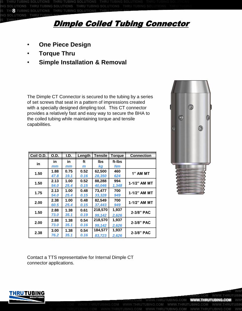
Dimple Coiled Tubing Connector
The Dimple CT Connector is secured to the tubing by a series
of set screws that seat in a pattern of impressions created
with a specially designed dimpling tool. This CT connector
provides a relatively fast and easy way to secure the BHA to
the coiled tubing while maintaining torque and tensile
capabilities.
Contact a TTS representative for Internal Dimple CT
connector applications.
• One Piece Design
• Torque Thru
• Simple Installation & Removal
Coil O.D. O.D. I.D. Length Tensile Torque Connection
in in
mm
in
mm
ft
m
lbs
kg
ft-lbs
Nm
1.50 1.88
47.8
0.75
19.1
0.52
0.16
62,500
28,350
460
624 1” AM MT
1.50 2.13
54.0
1.00
25.4
0.52
0.15
88,288
40,046
994
1,348 1-1/2” AM MT
1.75 2.13
54.0
1.00
25.4
0.48
0.15
73,477
33,328
700
949 1-1/2” AM MT
2.00 2.38
60.5
1.00
25.4
0.48
0.15
82,549
37,443
700
949 1-1/2” AM MT
1.50 2.88
73.0
1.38
35.1
0.61
0.19
218,570
99,142
1,937
2,626 2-3/8” PAC
2.00 2.88
73.0
1.38
35.1
0.54
0.16
218,570
99,142
1,937
2,626 2-3/8” PAC
2.38 3.00
76.2
1.38
35.1
0.54
0.16
184,577
83,723
1,937
2,626 2-3/8” PAC

9
Coil O.D. O.D. I.D. Length Connection
in in
mm
in
mm
ft
m
1.00 1.25
31.8
0.63
15.9
0.49
0.15 7/8” AM MT
1.25 1.25
31.8
0.63
15.9
0.49
0.15 7/8” AM MT
1.50 1.50
38.1
0.69
17.5
0.54
0.16 1” AM MT
1.50 1.94
49.3
0.69
17.5
0.63
0.19 1-1/2” AM MT
1.75 1.75
44.5
0.75
19.1
0.58
0.18 1” AM MT
1.75 1.94
49.3
0.75
19.1
0.63
0.19 1-1/2” AM MT
2.00 2.00
50.8
0.75
19.1
0.63
0.19 1” AM MT
2.00 2.00
50.8
0.75
19.1
0.63
0.19 1-1/2” AM MT
Anti-Rotation Roll-On Connector
The Anti-Rotation Roll-On Connector (AROC) is an
improvement on standard roll-on connectors. The AROC
provides superb torque thru capabilities while maintaining a
slick OD and simple installation requirements.
• Torque Thru
• Slick OD

10
O.D. I.D. Length Tensile Torque Connection
in
mm
in
mm
ft
m
lbs
kg
ft-lbs
Nm
1.70
43.2
0.69
17.5
1.29
0.39
39,850
18,076
460
624 1” AM MT
2.13
54.0
1.00
25.4
1.70
0.52
70,630
32,037
944
1,280 1-1/2” AM MT
2.88
73.0
1.00
25.4
1.41
0.43
188,980
85,720
4,011
5,438 2-3/8” PAC
Dual Back Pressure Valve
The Dual Back Pressure Valve is designed to provide a
means of shutting-off the coiled tubing from within the well.
This tool can be used to simply prevent flow up the bottom
hole assembly.
• Maintains Well Control
• Large I.D. for Ball Passage
• Dual for Back-Up

11
Back Pressure Float Valve
The Back Pressure Float Valve is primarily used with jointed
pipe operations where continuous flushing, due to pipe
manipulation, can stir up debris and prevent most types of
valves from sealing properly. This tool is very tolerant of
debris laden fluids and provides an additional safety barrier
aside from typical valves included in the BHA.
• Utilizes Industry Standard Plunger
Valve Cartridge
• Provides Metal-to-Metal and
Elastomeric Seal
• Debris Tolerant
O.D. Length Tensile Torque Connection
in
mm
ft
m
lbs
Kg
ft-lbs
Nm
2.88
73.0
1.33
0.41
163,653
74,232
4,489
6,086 2-3/8” PAC
Back Pressure Float Valve – Box Up
O.D. Length Tensile Torque Connection
in
mm
ft
m
lbs
Kg
ft-lbs
Nm
3.06
77.2
1.10
0.34
218,570
99,142
4,489
6,086 2-3/8” PAC
Float Valve Bit Sub – Pin Up

12
O.D. I.D. Length Tensile Torque Connection
in
mm
in
mm
ft
m
lbs
kg
ft-lbs
Nm
1.70
43.2
0.45
11.5
1.43
0.44
43,000
19,505
625
847 1” AM MT
2.13
54.1
0.53
13.5
1.74
0.53
60,000
27,216
944
1,280 1-1/2” AM MT
2.88
73.0
0.69
17.5
2.24
0.68
115,200
52,254
3,086
4,184 2-3/8” PAC
Hydraulic Disconnect
The Hydraulic Disconnect is an essential piece of equipment
used for releasing the coiled tubing from the bottom hole
assembly if it has become stuck while in the wellbore.
Features include “hidden” internal shear screws that are fully
retained and cannot come loose. This design transmits
torque by use of internal splines that are far more durable
than standard external “castles” which are more susceptible
to damage.
• Transmits Torque
• Standard G.S. Type Internal Fishing
Profile
• Impact Resistant to Jarring

13
Coil O.D. O.D. I.D. Length Tensile Torque Connection
in in
mm
in
mm
ft
m
lbs
kg
ft-lbs
Nm
1.25 1.70
43.2
0.45
11.5
2.59
0.79
15,000
6,804
625
847 1” AM MT
1.25 2.13
54.0
0.53
13.5
2.95
0.90
30,000
13,608
944
1,280 1-1/2” AM MT
1.50 2.13
54.0
0.53
13.5
2.95
0.90
30,000
13,608
944
1,280 1-1/2” AM MT
1.50 2.88
73.0
0.69
17.5
3.62
1.10
45,000
20,412
1,500
2,034 2-3/8” PAC
1.75 2.88
73.0
0.69
17.5
3.73
1.14
50,000
22,680
1,500
2,034 2-3/8” PAC
2.00 2.88
73.0
0.69
17.5
3.77
1.15
52,000
23,587
1,500
2,034 2-3/8” PAC
Motor Head Assembly
The Motor Head Assembly serves as a multi-function tool.
This tool was developed to be run primarily with a downhole
motor. The Motor Head Assembly combines the coiled tubing
connector, dual back pressure valve, and hydraulic
disconnect into one compact tool. Utilizing this tool in the
bottom hole assembly greatly shortens the overall length of
the complete tool string. A shorter bottom hole assembly
requires less lubricator, allowing for a much safer rig up of the
coiled tubing injector head. The components can also be
separated into different configurations depending on specific
requirements.
• Slip Type Connector
• Dual Flapper Valve
• Standard Fishing Profile
• No Exposed Shear Screws
Other configurations on next page.
Complete MHA (CTC, BPV & HD)

14
Motor Head Assembly
Coil O.D. O.D. I.D. Length Tensile Torque Connection
in in
mm
in
mm
ft
m
lbs
kg
ft-lbs
Nm
1.25 1.70
43.2
0.69
17.5
1.95
0.59
15,000
6,804
460
624 1” AM MT
1.25 2.13
54.0
1.00
25.4
2.46
0.75
30,000
13,608
944
1,280 1-1/2” AM MT
1.50 2.13
54.0
1.00
25.4
2.46
0.75
30,000
13,608
944
1,280 1-1/2” AM MT
1.50 2.88
73.0
1.00
25.4
2.89
0.88
45,000
20,412
1,500
2,034 2-3/8” PAC
1.75 2.88
73.0
1.00
25.4
3.00
0.91
50,000
22,680
1,500
2,034 2-3/8” PAC
2.00 2.88
73.0
1.00
25.4
1.64
0.50
52,000
23,587
1,500
2,034 2-3/8” PAC
CT Connector & Back Pressure Valve
O.D. I.D. Length Tensile Torque Connection
in
mm
in
mm
ft
m
lbs
kg
ft-lbs
Nm
1.70
43.2
0.45
11.5
1.80
0.55
39,850
18,076
460
624 1” AM MT
2.13
54.0
0.53
13.5
2.20
0.67
60,000
27,216
944
1,280 1-1/2” AM MT
2.88
73.0
0.69
17.5
2.74
0.84
115,200
52,254
3,086
4,184 2-3/8” PAC
Back Pressure Valve & Hyd. Disconnect
O.D. I.D. Length Tensile Torque Connection
in
mm
in
mm
ft
m
lbs
kg
ft-lbs
Nm
2.88
73.0
0.56
14.2
3.40
1.04
144,000
65,317
1,900
2,576 2-3/8” PAC
Hyd. Disconnect & Circulating Sub

15
O.D. I.D. Length Tensile Torque Connection
in
mm
in
mm
ft
m
lbs
kg
ft-lbs
Nm
1.70
43.2
0.38
9.5
0.83
0.25
50,000
22,680
459
622 1” AM MT
2.13
53.9
0.44
11.1
1.15
0.35
88,288
40,047
994
1,348 1-1/2” AM MT
2.88
73.0
0.56
14.3
1.58
0.48
188,980
85,720
1,937
2,626 2-3/8” PAC
3.13
79.5
0.56
14.3
1.78
0.54
281,160
127,532
4,600
6,237 2-3/8” REG
4.20
106.7
0.81
20.6
2.57
0.78
405,000
183,705
1,650
2,237 3-1/2” PH-6
O.D. I.D. Length Tensile Torque Connection
in
mm
in
mm
ft
m
lbs
kg
ft-lbs
Nm
1.70
43.2
0.38
9.7
0.83
0.25
62,500
28,350
460
624 1” AM MT
2.13
53.9
0.44
11.1
1.15
0.35
88,288
40,047
994
1,348 1-1/2” AM MT
2.88
73.0
0.56
14.3
1.58
0.48
188,980
85,720
1,937
2,626 2-3/8” PAC
Circulating Sub
The Circulating Sub, normally run above a downhole motor, is
designed to provide a means of circulation to the annulus
upon activation. This tool utilizes a drop ball for actuation.
• Saves Wear on Motor
• Circulating Path
• Dual Option Available with Rupture
Disk
Dual Circulating Sub
Diverting Circulating Sub

16
O.D. I.D. Length Tensile Torque Connection
in
mm
in
mm
ft
m
lbs
kg
ft-lbs
Nm
2.88
73.0
0.88
22.2
5.26
1.60
201,900
91,580
2,465
3,342 2-3/8” PAC
HydraSet™ CT Jar
The HydraSet™ CT Jar is used to free immobilized tool
strings in the wellbore. The innovative design of this tool
allows continual pumping through the jar during the firing and
reset process. An overbalanced section in the assembly
provides operators the option to reset the jar hydraulically by
increasing the differential pressure within the tool thus,
reducing cycling fatigue on coiled tubing. Additional
overbalanced sections can be added to the assembly to
adjust the differential pressure required to reset the jar for
subsequent impacts. The rugged design and hydraulic assist
feature make this tool ideal for use with extended reach tools
and in long lateral well sections where it may be difficult to
apply enough set-down weight to operate conventional jarring
tools.
• Engineered for Horizontal Applications
• Low Reset Force Requirement
• Hydraulic Reset Option/Assist
• High Impact Ratio
• Rugged, Compact Design
• Permits Circulation During Operation
HydraSet™ Bi-Directional CT Jar
HydraSet™ CT Jar
O.D. I.D. Length Tensile Torque Connection
in
mm
in
mm
ft
m
lbs
kg
ft-lbs
Nm
2.88
73.0
0.88
22.2
9.05
2.76
201,900
91,580
2,465
3,342 2-3/8” PAC

17
HZ Impact Jar
The HZ Impact Jar can be fired up or down multiple times
simply by pushing or pulling on the immobilized tool string. A
very low re-cocking force makes this design ideal for
horizontal wells where pushing capabilities are limited. The
jarring impact can easily be controlled by varying the applied
force. No pre-setting or adjustments are needed before
tripping in the hole or prior to jarring. A large thru bore is
incorporated allowing ball actuated tools to be run below the
jar.
• Low Re-Cocking Force
• Engineered for Horizontal Applications
• Neutral Position
• High Impact
HZ Impact Jar O.D. I.D. Length Tensile Torque Connection
in
mm
in
mm
ft
m
lbs
kg
ft-lbs
Nm
1.70
43.2
0.56
14.2
6.10
1.86
52,400
23,768
355
481 1” AM MT
2.13
54.0
0.69
17.5
6.10
1.86
91,302
41,414
628
851 1-1/2” AM MT
O.D. I.D. Length Tensile Torque Connection
in
mm
in
mm
ft
m
lbs
kg
ft-lbs
Nm
1.70
43.2
0.56
14.2
5.95
1.81
52,400
23,768
355
481 1” AM MT
2.13
54.0
0.69
17.5
5.94
1.81
91,302
41,414
628
851 1-1/2” AM MT
2.88
73.0
0.88
22.4
4.30
1.31
211,535
95,951
2,465
3,342 2-3/8” PAC
HZ Bumper Jar

18
O.D. Length Tensile Torque Connection
in
mm
ft
m
lbs
kg
ft-lbs
Nm
2.19
55.6
3.65
1.11
73,256
33,228
994
1,348 1” AM MT
2.88
73.0
2.54
0.77
188,980
85,720
1,937
2,626 1-1/2” AM MT
4.75
120.7
6.41
1.95
538,368
244,200
16,414
22,250 2-3/8” PAC
Achiever Vibrating Tool
Thru Tubing Solutions’ Achiever Vibrating Tool is used
primarily in horizontal wells where friction can cause the
coiled tubing to friction lock due to helical buckling as the tool
string is pushed further into laterals. This patent pending
design allows operators to reach their targeted depths with
much less resistance.
• No External Moving Parts
• Low Maintenance Cost
• Shorter Length Than Competitors
• N2 Compatible
• Operates in High Temperatures

19
O.D. Length Tensile Torque Flow Rate Connection
in
mm
ft
m
lbs
kg
ft-lbs
Nm
bpm
Lpm
1.69
43.2
1.20
0.37
53,679
24,348
460
624
1
159 1” AM MT
2.13
54.0
1.39
0.42
84,005
38,104
994
1,348
1.5
238 1-1/2” AM MT
2.88
73.0
1.65
0.50
159,271
72,244
2,300
3,118
2
318 2-3/8” PAC
2.88
73.0
1.65
0.50
159,271
72,244
2,300
3,118
3
477 2-3/8” PAC
3.50
88.9
2.79
0.85
273,000
123,831
4,400
5,966
4
636 2-7/8” PH-6
3.50
88.9
2.79
0.85
273,000
123,831
4,400
5,966
5
795 2-7/8” PH-6
XRV™ – X-Tended Reach Vibratory Tool
Thru Tubing Solutions’ XRV™ is a dynamic excitation tool
that enables coiled tubing to reach depths that were
previously unobtainable. Designed without any moving parts
or elastomers, this tool can handle virtually any environment,
chemical or temperature.
The XRV™ is the shortest, most reliable friction reducing tool
on the market.
• Unlimited Temperature Range
• Wide Range of Operational Flow Rates
• Uses No Elastomers
• N2 Compatible

20
O.D. I.D. Length Tensile Torque Connection
in
mm
in
mm
ft
m
lbs
kg
ft-lbs
Nm
1.70
43.2
0.53
13.5
1.30
0.40
21,000
9,525
418
567 1” AM MT
2.13
54.0
0.81
20.6
1.28
0.39
22,300
10,115
937
1,270 1-1/2” AM MT
2.88
73.2
1.00
25.4
1.67
0.51
59,300
26,898
1,760
2,386 2-3/8” PAC
Lockable Swivel
The Lockable Swivel was designed to allow for long bottom
hole assemblies to be made up to the coiled tubing
connector. This tool allows for rotation at the swivel instead
of rotating the entire bottom hole assembly.
• Sealed Assembly
• Torque Thru Capabilities
• Optional Locking Mechanism

21
O.D. I.D. Length Tensile Torque Connection
in
mm
in
mm
ft
m
lbs
kg
ft-lbs
Nm
2.88
73.2
1.00
25.4
1.75
0.53
132,300
60,010
2,110
2,861 2-3/8” PAC
4.75
120.7
2.00
50.8
2.67
0.81
343,000
155,582
8,600
11,660 3-1/2” IF
Safety Union
The Safety Union was designed to allow for long assemblies
to be made up without wrenches overhead, providing for a
safer working environment and limiting exposure under the
injector head.
• Safer/Easier Way to Make-Up Tools
• Eliminates Over-Head Wrenching
• Limited Time Under Injector Head

22
O.D. I.D. Length Tensile Torque Connection
in
mm
in
mm
ft
m
lbs
kg
ft-lbs
Nm
1.70
43.2
0.53
13.5
0.95
0.29
45,000
20,412
308
418 1” AM MT
2.13
54.0
0.59
15.0
1.16
0.35
70,600
32,024
532
721 1-1/2” AM MT
2.88
73.2
0.78
20.0
1.67
0.51
130,991
59,417
1,140
1,546 2-3/8” PAC
Torque-Thru Sealed Knuckle Joint
The Torque-Thru Sealed Knuckle Joint will allow for torque to
be transmitted through the tool while providing some flexibility
to a ridged bottom hole assembly and reducing any
unnecessary side loads. The Knuckle Joint is also sealed to
allow fluid to pass through for washing or operating any
hydraulic tools below it.
• Sealed
• 360 Degree Articulation
• Torque Thru Capabilities

23
Nom. O.D. I.D. Length Tensile Torque Connection
in
mm
in
mm
ft
m
lbs
kg
ft-lbs
Nm
1-11/16 Go 1.81
45.9
0.31
7.9
3.63
1.12
24,681
11,195 N/A 1” AM MT
#5 1.81
45.9
0.31
7.9
3.32
1.01
24,681
11,195 N/A 1” AM MT
#10 3.13
79.5
0.44
11.2
2.44
0.74
61,000
27,669
350
475 2-3/8” PAC
#20 3.81
96.7
0.44
11.2
2.50
0.76
115,000
52,163
1,025
1,390 2-3/8” PAC
Hydraulic Setting Tool
Thru Tubing Solutions’ Hydraulic Setting Tool is the shortest
on the market making it ideal for horizontal applications. The
unique flow-thru feature allows for washing away any
sediment or debris that could prevent a plug from sealing or
engaging properly.
• Short Tool Length
• Compatible with Standard Plugs
• Flow Thru Capabilities
• Can be Run with Perforators

24
O.D. I.D. Length Tensile Torque Connection
in
mm
in
mm
ft
m
lbs
kg
ft-lbs
Nm
1.70
43.2
1.13
29.0
3.84
1.17
49,811
22,594
460
624 1” AM MT
2.13
54.0
1.50
38.1
4.39
1.34
70,630
32,037
994
1,348 1-1/2” AM MT
2.88
73.0
2.00
50.8
4.32
1.32
115,000
52,163
2,110
2.861 2-3/8” PAC
Venturi Junk Basket
The Venturi Junk Basket works by pumping fluid or nitrogen
down the coiled tubing creating a venturi action. This causes
suction at the bottom of the tool pulling debris into the basket
where it is trapped. Finger grabs hold the debris until it can
be removed from the well bore. The Venturi Basket may also
be run with a motor.
• Removes Loose Debris
• Various Extension Lengths
• Milling Option Available

25
O.D. I.D. Length Tensile Torque Connection
in
mm
in
mm
ft
m
lbs
kg
ft-lbs
Nm
1.70
43.2
0.50
12.7
2.37
0.72
61,400
27,851
460
624 1” AM MT
2.13
54.0
0.50
12.7
2.49
0.76
88,288
40,047
994
1,348 1-1/2” AM MT
2.88
73.0
0.63
16.0
2.51
0.77
188,980
85,720
1,937
2,626 2-3/8” PAC
Boot Basket
The Boot Basket is used to collect debris that is too large to
be carried out of the hole by normal circulation. The Boot
Basket is designed to create a change in velocity around the
upper end of the tool, allowing debris to fall into the cavity
between the skirt and mandrel.
• Collects Loose Debris
• Solid Construction
• Full Flow Thru
26
Nom O.D. Length Tensile Torque Connection
in
mm
ft
m
lbs
kg
ft-lbs
Nm
3.50 3.60
91.4
4.91
1.50
62,500
28,350
460
624 2-3/8” PAC
3.63 3.88
98.6
4.91
1.50
62,500
28,350
460
624 2-3/8” PAC
4.00 4.50
114.3
5.87
1.79
88,288
40,047
994
1,348 2-3/8” PAC
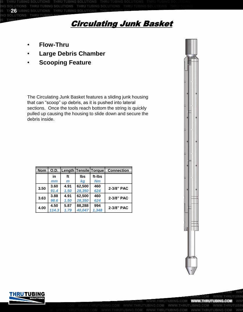
Circulating Junk Basket
The Circulating Junk Basket features a sliding junk housing
that can “scoop” up debris, as it is pushed into lateral
sections. Once the tools reach bottom the string is quickly
pulled up causing the housing to slide down and secure the
debris inside.
• Flow-Thru
• Large Debris Chamber
• Scooping Feature

27
Nipple Locator
The Nipple Profile Locator gives a simple means of depth
location. Run on coiled tubing or slickline, the nipple profile
locator gives an overpull when passing through a standard
nipple. Depth location can then be correlated back to the
coiled tubing counter wheel.
• Bi-Directional Indication
• Torque Thru
• Flow Thru
O.D. I.D. Length Tensile Torque Connection
in
mm
in
mm
ft
m
lbs
kg
ft-lbs
Nm
1.70
43.2
0.69
17.5
1.74
0.53
49,100
22,271
1,340
1,817 1” AM MT
2.13
54.0
0.81
20.6
2.00
0.61
31,000
14,061
1,320
1,790 1-1/2” AM MT

28
O.D. I.D. Length Tensile Torque Connection
in
mm
in
mm
ft
m
lbs
kg
ft-lbs
Nm
1.70
43.2
0.56
14.2
3.75
1.14
34,900
15,830
507
687 1” AM MT
2.13
54.0
0.56
14.2
3.75
1.14
42,340
19,205
1,043
1,414 1-1/2” AM MT
2.88
73.2
1.00
25.4
4.00
1.22
95,990
43,540
3,370
4,569 2-3/8” PAC
O.D. I.D. Length Tensile Torque Connection
in
mm
in
mm
ft
m
lbs
kg
ft-lbs
Nm
1.70
43.2
0.56
14.2
4.92
1.50
56,600
25,673
507
687 1” AM MT
2.13
54.0
0.56
14.2
5.13
1.56
99,680
45,214
1,043
1,414 1-1/2” AM MT
2.88
73.2
1.00
25.4
5.25
1.60
200,800
91,081
3,370
4,569 2-3/8” PAC
Bow Spring Centralizer
The Bow Spring Centralizer is used to centralize the BHA
inside larger tubing or casing after it has passed through a
restricted ID. The Centralizer is designed for the springs to
be at constant maximum expansion.
• Centralizes Tool String
• Flow Thru Capabilities
• Large Expansion
Hydraulic Type
Mechanical Type

29
Weight Bar
The use of a weight bar can increase the amount of impact
applied at the fish while running in tandem with a Jar and
Accelerator.
• Added Impact While Jarring
• Custom Made
• Allows Greater Hammer Effect
O.D. I.D. Length Tensile Torque Connection
in
mm
in
mm
ft
m
lbs
kg
ft-lbs
Nm
1.70
43.2
0.75
19.1
5.00
1.52
62,500
28,350
460
624 1” AM MT
1.70
43.2
0.75
19.1
10.00
3.05
62,500
28,350
460
624 1” AM MT
2.13
54.0
1.00
24.5
5.00
1.52
88,288
40,047
994
1,348 1-1/2” AM MT
2.13
54.0
1.00
24.5
10.00
3.05
88,288
40,047
994
1,348 1-1/2” AM MT
2.88
73.0
1.38
34.9
5.00
1.52
188,980
85,720
1,937
2,626 2-3/8” PAC
2.88
73.0
1.38
34.9
10.00
3.05
188,980
85,720
1,937
2,626 2-3/8” PAC

30
High Velocity Abrasive Perforator
The High Velocity Abrasive Perforating Tool has special port
design and positioning for directing an abrasive fluid through
tubing or casing into the formation. Running this tool with a
special mixture of abrasive fluids accomplishes a complete
perforation of the well. Because of the design of the Abrasive
Perforating System, multiple perforations are possible on a
single trip in the hole. Case histories have shown over 200
perforations on a single trip. Custom tool designs are
available to provide the desired perforations per foot.
Not only is this system a viable alternative to TCP or
conventional wireline perforating, but it can also perforate
wells where other systems are not an option. The system
has proven successful in perforating drill collars, drill pipe,
and multiple casing strings in a single trip.
We recommend contacting a Thru Tubing Solutions
representative to determine the exact configuration for a
given situation.
• Multiple Zone Perforation on One Trip
• Heavy Wall Perforation
• Horizontal Well Applications
• Custom Sizes Available

31
High Velocity Abrasive Cutter
The High Velocity Abrasive Cutting Tool has special port
positioning for directing an abrasive fluid jet stream into the ID
of the pipe to be severed. Running this tool with the Titan
down hole motor and a special mixture of abrasive fluids
accomplishes a complete severing of the tubular. As this tool
rotates below the motor, the abrasive fluids penetrate and
sever the tube where the jet stream makes contact. The
result is a clean cut without any flaring of the tubular.
We recommend contacting a Thru Tubing Solutions
representative for determining the exact tool for a given
situation.
• Ability to Cut Tubing, Casing,
Completion Components, Drill Pipe &
Drill Collars
• Horizontal Well Applications
• Clean Cut, No Flared Ends After Cut
• Custom Sizes Available

32
Overshot
Thru Tubing Solutions specializes in restricted I.D. fishing
with a wide assortment of overshots. Sizes range from 1-
21/32” to 4-1/8” O.D. (specialty overshots available upon
request).
• Specialty Bowls and Grapples
• Standard and Oversize Guides
• Premium Thread Top Subs
• Series 10, 20, 70 & 150

33
O.D. I.D. Length Tensile Torque Catch Range Connection
in
mm
in
mm
ft
m
lbs
kg
ft-lbs
Nm in
1.86
47.2
1.31
33.4
2.05
0.62
31,300
14,197
1,010
1,369 1” to 1-1/4” 1-1/4” CS
2.06
52.3
1.31
33.4
2.45
0.75
65,000
29,484
800
1,085 1” to 1-1/4” 1-1/4” CS
2.70
68.6
1.81
46.1
2.46
0.75
62,000
28,123
2,250
3,051 1” to 1-3/4” 2-3/8” CS
3.13
79.3
1.88
47.8
2.83
0.86
84,000
38,102
2,950
4,000 1” to 1-3/4” 2-3/8” CS
3.38
85.7
2.13
53.9
2.64
0.80
91,000
41,322
4,560
6,182 1” to 2” 2-7/8” CS
Continuous Tubing Overshot
The continuous tubing overshot is used to retrieve coiled
tubing or threaded pipe. This overshot is a non-releasable
tool designed to swallow large sections without dulling
grapples.
• Wide Catch Range
• Swallow Large Sections of Tubing
• Coiled Tubing or Threaded Pipe

34
O.D. I.D. Length Tensile Torque Catch Range Connection
in
mm
in
mm
ft
m
lbs
kg
ft-lbs
Nm in
2.06
52.4
1.31
33.4
1.96
0.60
65,000
29,484
1,360
1,844 1” to 1-1/4” 1-1/2” CS
2.50
63.5
1.56
39.7
2.98
0.91
74,000
33,566
2,440
3,308 1-1/2” 2-1/16” CS
2.70
68.6
1.81
46.1
3.25
0.99
62,000
28,123
2,250
3,051 1-1/4” to 1-3/4” 2-3/8” CS
3.38
85.7
2.13
53.9
2.90
0.88
91,000
41,280
4,580
6,210 1-3/4” to 2” 2-7/8” CS
Cutting Overshot
The Snipper Overshot is used to cut and retrieve coiled
tubing that has been parted, stuck or abandoned in the well
bore. Once the appropriate overpull is reached screws are
sheared causing the blades to sever the coiled tubing. A
clean fishing neck is left looking up.
• Retrieve Cut Segment
• Reduced Overpull and Necking of Coil
• Leaves Clean Cut
• Coiled Tubing or Threaded Pipe

35
Overshot Pack-Off Sub
The Pack-off Sub is designed to be run above the Continuous
Tubing or Cutting Overshot. The Pack-off Sub creates a seal
between the work string and the fish. Circulation can then be
maintained through the fish.
• Tubing or Coiled Tubing
• 5000 psi
• Maintain String Pressure Integrity
O.D. I.D. Length Tensile Torque Catch Range Connection
in
mm
in
mm
ft
m
lbs
kg
ft-lbs
Nm in
1.86
47.2
1.30
33.0
1.03
0.31
69,000
31,298
1,010
1,369 1” to 1-1/4” 1-1/4” CS
2.06
52.3
1.30
33.0
1.18
0.36
52,000
23,587
1,258
1,706 1” to 1-1/4” 1-1/4” CS
2.70
68.6
1.81
46.1
1.30
0.40
47,200
21,410
2,160
2,929 1” to 1-3/4” 2-3/8” CS
3.13
79.3
1.81
46.1
1.67
0.51
90,400
41,005
3,890
5,274 1” to 1-3/4” 2-3/8” CS
3.38
85.7
2.09
53.2
1.48
0.45
102,000
46,266
4,770
6,468 1-1/2” to 2” 2-7/8” CS

36
GS Profile O.D. I.D. Length Tensile Connection
Nom. in
mm
in
mm
ft
m
lbs
kg
2 1.81
46.1
0.19
4.8
1.76
0.54
31,200
14,152 1” AM MT
2-1/2 2.13
53.9
0.25
6.4
2.13
0.65
45,400
20,593 1-1/2” AM MT
3 2.88
73.0
0.25
6.4
2.77
0.84
68,000
30,844 2-3/8” PAC
GS Profile O.D. I.D. Length Connection
Nom. in
mm
in
mm
ft
m
2 1.75
44.5
0.19
4.8
0.97
0.30 1” AM MT
2-1/2 2.16
54.9
0.31
7.8
0.99
0.30 1-1/2” AM MT
3 2.88
73.0
0.50
12.7
1.01
0.31 2-3/8” PAC
GS Spear
The GS Spear is used to retrieve a device with an internal
fishing neck profile. The Spear is designed to withstand high
side and tensional loads during a jarring operation. Thru
Tubing Solutions utilizes two types of GS spears. Both
mechanical and hydraulic spears have special applications
depending on well conditions.
• Continuous Flow Thru
• Withstands High Tensile Forces
• Jar Down to Release (Mechanical)
• Flow Release Type (Hydraulic)
Mechanical Type
Hydraulic Type

37
GS Profile O.D. Length Tensile Connection
Nom. in
mm
ft
m
lbs
kg
2 1.81
46.1
1.76
0.54
31,200
14,152 1” AM MT
2-1/2 2.13
53.9
2.13
0.65
45,400
20,593 1-1/2” AM MT
3 2.88
73.0
2.77
0.84
68,000
30,844 2-3/8” PAC
GS Profile O.D. Length Connection
Nom. in
mm
ft
m
2 1.88
47.2
1.20
0.37 1” AM MT
2-1/2 2.25
57.2
1.23
0.37 1-1/2” AM MT
3 2.80
71.0
1.25
0.38 2-3/8” PAC
JDC Overshot
The JDC Overshot is available in both hydraulic and
mechanical versions. These tools are used to latch an
external fishing neck found on some locks and probes.
Utilizing coiled tubing, fluid is pumped through the tool. Sand
or debris can then be circulated out of the way, exposing the
fishing neck. Once the fishing neck is latched, over-pull is
applied. Jars may also be utilized to assist in removing the
fish.
• Hydraulic and Mechanical Versions
• Withstands High Jar Impacts
• Pump Through Capabilities
Mechanical Type
Hydraulic Type

38
O.D. I.D. Length Tensile Connection
in
mm
in
mm
ft
m
lbs
kg
2.13
54.0
0.75
19.1
2.47
0.75
63,900
28,985 1” AM MT
2.25
57.2
0.75
19.1
2.48
0.76
101,600
46,085 1” AM MT
3.63
92.2
1.38
34.9
3.15
0.96
188,980
85,720 2-3/8” PAC
4.50
114.2
1.38
34.9
3.25
0.99
188,980
85,720 2-3/8” PAC
Pump-Thru Wire Grab
The Wire Grab is used as a means of removing lost slickline,
electric line, or braided line in the well bore. The barbs on
the tool entangle with the lost wire allowing the wire to be
retrieved.
We recommend contacting a Thru Tubing Solutions
representative to determine the exact configuration for a
given situation.
• Retrieve Lost Wireline
• Pump Thru

39
Pump-Thru Rope Spear
The Rope Spear is used as a means of removing lost
slickline, electric line, or braided line in the well bore. The
barbs on the tool entangle with the lost wire allowing the wire
to be retrieved.
We recommend contacting a Thru Tubing Solutions
representative to determine the exact configuration for a
given situation.
• Retrieve Lost Wireline
• Pump Thru
O.D. I.D. Length Tensile Connection
in
mm
in
mm
ft
m
lbs
kg
2.88
73.0
0.75
19.1
3.80
1.16
132,500
60,101 2-3/8” PAC
3.50
88.9
0.75
19.1
3.80
1.16
132,500
60,101 2-3/8” PAC

40
Deployment Bar
The deployment bar is used to deploy long bottom hole
assemblies into and out of the well. A deployment bar in the
bottom hole assembly allows the capability of closing the
BOP rams and slips for adding or removing a segment of the
bottom hole assembly. This limits the amount of lubricator
needed.
• Deploy Long Bottom Hole Assemblies
• O.D. to Match Coil O.D.
Dep. O.D. O.D. I.D. Length Tensile Torque Connection
in in
mm
in
mm
ft
m
lbs
kg
ft-lbs
Nm
1.25 1.70
43.2
0.75
19.1
10.00
3.05
62,500
28,350
460
624 1” AM MT
1.50 1.70
43.2
0.75
19.1
10.00
3.05
62,500
28,350
460
624 1” AM MT
1.25 2.13
54.0
0.75
19.1
1.27
0.39
70,630
32,037
944
1,280 1-1/2” AM MT
1.50 2.13
54.0
0.75
19.1
1.27
0.39
24,000
10,886
400
542 1-1/2” AM MT
1.75 2.13
54.0
0.75
19.05
1.27
0.39
24,000
10,886
400
542 1-1/2” AM MT
1.50 2.88
73.0
1.13
28.7
1.49
0.45
105,400
47,809
1,220
1,654 2-3/8” PAC
1.75 2.88
73.0
1.13
28.7
1.60
0.49
50,000
22,680
1,200
1,627 2-3/8” PAC
2.00 2.88
73.0
1.38
35.1
1.64
0.50
65,000
29,484
2,300
3,118 2-3/8” PAC

41
O.D. Length Tensile Torque Connection
in
mm
ft
m
lbs
kg
ft-lbs
Nm
3.06
77.8
1.02
0.31
143,461
65,073
2,975
4,034 2-3/8” 8 Rd
3.06*
77.8
1.02
0.31
199,320
90,410
3,813
5,170 2-3/8” 8 Rd
3.06
77.8
1.02
0.31
143,000
64,864
1,900
2,576 2-3/8” CS
3.68
93.3
1.29
0.39
143,461
65,073
2,975
4,034 2-7/8” 8 Rd
Pump-Off Check Valve
The Pump-Off Check Valve was developed primarily for the
snubbing and workover industry. This tool allows for
circulating sand and solids while tripping tubing in the hole
under pressure. Upon landing tubing at surface, a ball is
dropped and pumped down to the tool. This causes the
aluminum insert locking mechanism to shear and release.
Once released a full I.D. is left in the production tubing.
• Drop Ball for Actuation
• Flapper or Ball Check Valve
• Aluminum Insert
• Standard Tubing Connections
* Flapper Style Check Valve I.D. – 0.97 in (24.6 mm)

42
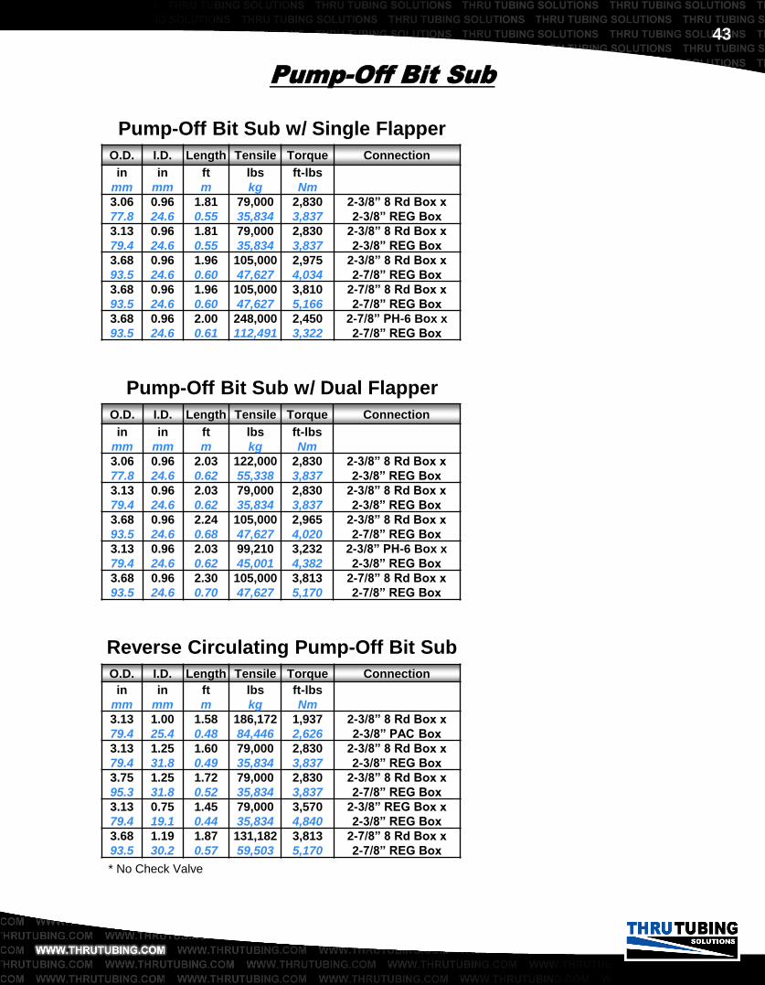
Pump-Off Bit Sub
The Pump-Off Bit Sub was developed for the Snubbing and
Workover Industry. This tool is used in conjunction with a Bit
or Mill to complete a workover operation. Upon completing
the drilling operation and landing the tubing at surface, a ball
is dropped and or pumped to the tool. As a result, pressure is
generated causing the locking mechanism to shear and
release. The bottom sub then separates and the well is ready
for production.
Thru Tubing Solutions offers four different styles of bit sub:
single flapper, double flapper, ball check and reverse
circulating.
• Drop Ball Actuated
• Torque Thru
• Balanced Piston
• Standard Connections
• High Tensile Strength
Other styles listed on next page.
O.D. Length Tensile Torque Connection
in
mm
ft
m
lbs
kg
ft-lbs
Nm
2.20
55.9
1.29
0.39
50,000
22,680
994
1,348
1-1/4” 10 Rd Box x
1-1/2” AM MT Box
3.13
79.4
1.85
0.56
79,000
35,834
2,830
3,837
2-3/8” 8 Rd Box x
2-3/8” REG Box
3.68
93.5
1.96
0.60
131,208
59,515
2,975
4,034
2-3/8” 8 Rd Box x
2-7/8” REG Box
3.68
93.5
1.96
0.60
131,208
59,515
3,813
5,170
2-7/8” 8 Rd Box x
2-7/8” REG Box
Pump-Off Bit Sub w/ Ball Check Valve
43
O.D. I.D. Length Tensile Torque Connection
in
mm
in
mm
ft
m
lbs
kg
ft-lbs
Nm
3.06
77.8
0.96
24.6
1.81
0.55
79,000
35,834
2,830
3,837
2-3/8” 8 Rd Box x
2-3/8” REG Box
3.13
79.4
0.96
24.6
1.81
0.55
79,000
35,834
2,830
3,837
2-3/8” 8 Rd Box x
2-3/8” REG Box
3.68
93.5
0.96
24.6
1.96
0.60
105,000
47,627
2,975
4,034
2-3/8” 8 Rd Box x
2-7/8” REG Box
3.68
93.5
0.96
24.6
1.96
0.60
105,000
47,627
3,810
5,166
2-7/8” 8 Rd Box x
2-7/8” REG Box
3.68
93.5
0.96
24.6
2.00
0.61
248,000
112,491
2,450
3,322
2-7/8” PH-6 Box x
2-7/8” REG Box
Pump-Off Bit Sub
O.D. I.D. Length Tensile Torque Connection
in
mm
in
mm
ft
m
lbs
kg
ft-lbs
Nm
3.13
79.4
1.00
25.4
1.58
0.48
186,172
84,446
1,937
2,626
2-3/8” 8 Rd Box x
2-3/8” PAC Box
3.13
79.4
1.25
31.8
1.60
0.49
79,000
35,834
2,830
3,837
2-3/8” 8 Rd Box x
2-3/8” REG Box
3.75
95.3
1.25
31.8
1.72
0.52
79,000
35,834
2,830
3,837
2-3/8” 8 Rd Box x
2-7/8” REG Box
3.13
79.4
0.75
19.1
1.45
0.44
79,000
35,834
3,570
4,840
2-3/8” REG Box x
2-3/8” REG Box
3.68
93.5
1.19
30.2
1.87
0.57
131,182
59,503
3,813
5,170
2-7/8” 8 Rd Box x
2-7/8” REG Box
O.D. I.D. Length Tensile Torque Connection
in
mm
in
mm
ft
m
lbs
kg
ft-lbs
Nm
3.06
77.8
0.96
24.6
2.03
0.62
122,000
55,338
2,830
3,837
2-3/8” 8 Rd Box x
2-3/8” REG Box
3.13
79.4
0.96
24.6
2.03
0.62
79,000
35,834
2,830
3,837
2-3/8” 8 Rd Box x
2-3/8” REG Box
3.68
93.5
0.96
24.6
2.24
0.68
105,000
47,627
2,965
4,020
2-3/8” 8 Rd Box x
2-7/8” REG Box
3.13
79.4
0.96
24.6
2.03
0.62
99,210
45,001
3,232
4,382
2-3/8” PH-6 Box x
2-3/8” REG Box
3.68
93.5
0.96
24.6
2.30
0.70
105,000
47,627
3,813
5,170
2-7/8” 8 Rd Box x
2-7/8” REG Box
Pump-Off Bit Sub w/ Dual Flapper
* No Check Valve
Pump-Off Bit Sub w/ Single Flapper
Reverse Circulating Pump-Off Bit Sub

44
O.D. I.D. Length Tensile Torque Connection
in
mm
in
mm
ft
m
lbs
kg
ft-lbs
Nm
3.67
93.2
0.97
24.6
1.88
0.57
199,320
90,410
3,049
4,134
2-7/8” EUE Box x
2-7/8” API REG Box
3.67
93.2
1.00
25.4
2.09
0.64
199,320
90,410
3,049
4,134
2-7/8” EUE Box x
2-7/8” API REG Box
3.67
93.2
0.97
24.6
1.83
0.56
136,940
62,115
2,975
4,034
2-3/8” EUE Box x
2-7/8” REG Box
Sliding Sleeve Bit Sub
The Sliding Sleeve Bit Sub was developed for the Snubbing
and Workover Industry. This tool is used in conjunction with a
Bit or Mill to complete a workover operation. Upon completing
the drilling operation and landing the tubing at surface, a ball
is dropped and or pumped to the tool. As a result, pressure is
generated causing the sleeve mechanism to shear. The inner
sleeve shifts down, exposing ports and the well is ready for
production without pumping anything into the bottom of the
well.
• Drop Ball Actuated
• Torque Thru
• Balanced Piston
• Standard Connections
• High Tensile Strength

45
O.D. I.D. Length Tensile Torque Connection
in
mm
in
mm
ft
m
lbs
kg
ft-lbs
Nm
1.60
40.6
0.58
14.7
1.07
0.33
70,000
31,752
500
678 1” CS
1.93
49.0
0.69
17.5
1.34
0.41
100,000
45,359
800
1,085 1-1/4” CS
2.18
55.3
1.00
25.4
1.42
0.43
120,000
54,431
1,000
1,356 1-1/2” CS
2.33
59.2
1.00
25.4
1.42
0.43
103,000
46,720
1,100
1,491 2-1/16” CS
2.92
74.3
1.00
25.4
1.72
0.52
237,000
107,501
3,400
4,610 2-3/8” PH-6
3.51
89.2
1.00
24.6
1.91
0.58
336,000
152,407
6,061
8,218 2-7/8” PH-6
4.31
109.5
1.00
25.4
1.57
0.48
285,000
129,274
3,800
5,152 3-1/2” PH-6
2.19
55.6
0.63
15.9
1.09
0.33
124,000
56,246
1,579
2,141 1-1/4” REG
3.13
79.4
1.00
25.4
1.78
0.54
298,999
135,624
3,232
4,382 2-3/8” REG
3.06
77.8
1.00
25.4
1.78
0.54
186,172
84,446
3,709
5,029 2-3/8” 8 Rd
3.67
93.2
1.00
25.4
2.00
0.61
199,320
90,410
3,813
5,170 2-7/8” 8 Rd
3.38
85.7
1.00
25.4
1.78
0.54
287,000
130,181
6,200
8,406 2-3/8” IF
4.75
120.7
1.00
25.4
1.41
0.43
538,368
244,000
1,281
1,737 3-1/2” IF
Snubbing Back Pressure Valve
The Snubbing Back Pressure Valve was designed to provide
a dependable method of well control. This tool is typically run
close to the bottom of the string to prevent fluid or gas from
entering the tubing string. The dual flappers allow for a ball to
pass through the tool and are more reliable than old style ball
checks or dart-type floats.
• Dual Flappers
• Two Piece Construction
• Teflon Seats
• Standard and Premium Connections
• No Ball and Seats to Wash Out

46
Relief Valve
The Relief Valve is designed to safely bleed pressure from
below a lock or back pressure valve. The plunger breaks the
seal of a flapper style check valve as it is threaded into the
main housing. The relief valve can be retro-fitted to
accommodate any TTS flapper type back pressure valve.
We recommend contacting a Thru Tubing Solutions
representative for determining the exact configuration for a
given situation.
• Safe Means of Relieving Pressure
• Jam Nut Pressure Seal
• Large By-Pass Area

47
Profile Nipple
Thru Tubing Solutions has a wide variety of both tubing and
drill pipe nipples. We specialize in high pressure dual flapper
style locks. Contact a TTS representative for profile and plug
specifications and recommendations.
• 8 Round and Premium Threads
• Drill Pipe Connections
• Wide Range of Profiles
Size & Profile Seal Bore No Go I.D.
Nom. in
mm
in
mm
1.710 „R‟ / „RN‟ 1.710
43.4
1.560
39.6
2.125 „R‟ / „RN‟ 2.125
53.8
1.937
49.2
2.188 „R‟ / „RN‟ 2.188
55.6
2.010
51.1
2.313 „R‟ / „RN‟ 2.313
58.7
2.131
54.1
2.563 „R‟ / „RN‟ 2.563
65.1
2.329
59.2
1.500 „X‟ / „XN‟ 1.500
38.1
1.448
36.8
1.875 „X‟ / „XN‟ 1.875
47.6
1.791
45.5
2.313 „X‟ / „XN‟ 2.313
58.7
2.205
56.0

48
Size & Profile No Go O.D. Min ID Eq. Flow Area
Nom. in
mm
in
mm
in2
cm2
1.710 „R‟ / „RN‟ 1.700
43.2
0.57
14.5
.049
0.32
2.125 „R‟ / „RN‟ 2.115
53.7
0.69
17.5
.028
0.18
2.188 „R‟ / „RN‟ 2.175
55.2
0.69
17.5
.049
0.32
2.313 „R‟ / „RN‟ 2.300
58.4
0.69
25.4
.049
0.32
2.563 „R‟ / „RN‟ 2.550
64.8
1.00
25.4
.041
0.26
1.500 „X‟ / „XN‟ 1.490
37.8
0.57
11.9
.014
0.09
1.875 „X‟ / „XN‟ 1.865
47.4
0.69
17.5
.028
0.18
2.313 „X‟ / „XN‟ 2.300
58.4
0.69
25.4
.014
0.09
Pump-Thru Lock
The Pump-Thru Lock is used primarily in the Snubbing
industry and provides the capability of setting, changing or
removing flow control equipment such as a Slickline Back
Pressure Valve. It utilizes locking keys that provide a positive
anchor within a nipple profile. This tool can either be run in
place or set and pulled via slickline. The Pump-Thru Lock
relies on a standard nipple profile and is capable of handling
many hours of continuous pumping.
• Slickline Set and Retrieved
• Utilizes Standard Nipple Profiles
• Equalizing Feature
• Dual Flappers

49
Coil O.D. O.D. I.D. Length Connection
in in
mm
in
mm
ft
m
1.25 1.25
31.8
0.63
16.0
0.13
0.04 7/8” AM MT
1.50 1.50
38.1
0.75
19.1
0.15
0.05 1” AM MT
1.75 1.75
44.5
0.75
19.1
0.15
0.05 1” AM MT
1.75 1.94
49.3
1.00
25.4
0.15
0.05 1-1/2” AM MT
2.00 2.00
50.8
1.00
25.4
0.17
0.05 1-1/2” AM MT
2.38 2.38
60.3
1.00
25.4
0.54
0.16 1-1/2” AM MT
2.63 2.63
66.7
1.38
35.1
0.50
0.15 2-3/8” PAC
Roll-On Connector
The coiled tubing roll-on connector is used as a simple
means of connecting the coiled tubing to a bottom hole
assembly. The roll-on connector is attached to the coiled
tubing by a method known as “crimping” the OD of the coiled
tubing.
The coiled tubing roll-on connector is available in a variety
of coiled tubing O.D. and weight configurations. The
connectors may also be customized to meet your
specifications.
• Keeps BHA Same O.D. as Coil
• Simple Installation

50
O.D. I.D. Length Tensile Torque Connection
in
mm
in
mm
ft
m
lbs
kg
ft-lbs
Nm
1.25
31.8
0.47
11.9
0.88
0.27
27,601
12,520
254
344 7/8” AM MT
1.50
38.1
0.58
14.7
1.08
0.33
62,500
28,350
460
624 1” AM MT
1.75
44.5
0.69
17.5
1.03
0.31
62,500
28,350
460
624 1” AM MT
2.00
50.8
1.00
25.4
1.17
0.36
66,600
30,209
898
1,218 1-1/2” AM MT
O.D. Length Tensile Torque Connection
in
mm
ft
m
lbs
kg
ft-lbs
Nm
1.25
31.8
0.59
0.18
27,601
12,520
327
443 7/8” AM MT
1.50
38.1
0.61
0.19
62,500
28,350
460
624 1” AM MT
1.75
44.5
0.61
0.19
62,500
28,350
460
624 1” AM MT
2.00
50.8
0.93
0.28
88,288
40,047
994
1,348 1-1/2” AM MT
Back Pressure Valve
The coiled tubing back pressure valve is run as a down hole
safety valve, preventing the flow upward inside of the coiled
tubing string. All of the internal components are replaceable,
allowing for simple redress of the complete back pressure
valve.
The coiled tubing back pressure valve is also available in a
variety of different styles and may also be customized to
meet your specifications.
• Replaceable Inserts
• Dual Flappers
• AM MT and Mini MT Connections
• Can Accommodate Downhole Screen
Ball Type Check Valve
Flapper Type Check Valve

51
O.D. I.D. Length Tensile Connection
in
mm
in
mm
ft
m
lbs
kg
1.25
31.8
0.44
11.2
0.86
0.26
27,601
12,520 7/8” AM MT
1.50
38.1
0.50
12.7
1.01
0.31
43,643
19,796 1” AM MT
1.75
44.5
0.50
12.7
1.10
0.34
26,250
11,907 1” AM MT
2.00
50.8
0.88
22.2
1.18
0.36
62,000
28,123 1-1/2” AM MT
Sealed Knuckle Joint
The coiled tubing sealed knuckle joint is used as a simple
point of flexibility in a rigid bottom hole assembly. Having this
component in the tool string maintains a sealed bottom hole
assembly, yet allows for movement below the knuckle joint.
• 360 Degree Articulation
• High Tensile

52
O.D. Length Connection
in
mm
ft
m
1.25
31.8
0.19
0.06 7/8” AM MT
1.50
38.1
0.28
0.09 1” AM MT
1.75
44.5
0.29
0.09 1” AM MT
2.00
50.8
0.29
0.09 1-1/2” AM MT
2.13
53.9
0.42
0.13 1-1/2” AM MT
2.88
73.0
0.71
0.22 2-3/8” PAC
Wash Nozzle
The coiled tubing wash nozzle is used to clean the inside of
well tubulars. While flowing through the wash nozzle a jetting
action occurs allowing for the removal of fill from within the
well bore. Selecting the appropriate nozzle configuration
along with appropriate velocity at the nozzle, allows removal
of residue such as salt, sand, mud, rust, and scale from the
well bore.
• High Velocity Nozzles
• Variety of Port Angles and Sizes
The coiled tubing wash nozzle is available in many
configurations. The nozzles may also be customized to meet
your specifications. We recommend contacting a Thru
Tubing Solutions representative for determining the exact tool
for a given situation.

53
O.D. Length Tensile Torque Connection
in
mm
ft
m
lbs
kg
ft-lbs
Nm
1.25
31.8
0.69
0.21
27,601
12,520
327
443 7/8” AM MT
1.50
38.1
0.77
0.23
62,500
28,350
460
624 1” AM MT
1.75
44.5
1.00
0.30
62,500
28,350
460
624 1” AM MT
2.00
50.8
1.16
0.35
88,288
40,047
994
1,348 1-1/2” AM MT
O.D. Length Tensile Torque Connection
in
mm
ft
m
lbs
kg
ft-lbs
Nm
1.50
38.1
1.01
0.31
29,726
13,484
334
453 1” AM MT
2.12
53.8
1.41
0.43
88,288
40,047
994
1,348 1-1/2” AM MT
Pump-Off Wash Nozzle
The pump-off wash nozzle allows for washing debris, such as
sand and solids while circulating the well bore. This tool
utilizes a ball check valve that prevents flow into the coiled
tubing string. Upon landing the string at the appropriate
depth, a ball is pumped down to the tool activating the
release mechanism. All of the internal components are then
pumped out leaving the coiled tubing ready for production.
• Balanced Piston
• High Velocity Nozzle
• Positive Lock Mechanism
Dual Flapper Type
Ball Type Check Valve

54
O.D. Length Flow Range Connection
in
mm
ft
m
bpm
Lpm
1.69
42.9
0.82
0.24
0.7 – 1.3
111 – 207 1” AM MT
2.13
53.9
1.33
0.41
0.8 – 2.0
127 – 318 1-1/2” AM MT
2.50
63.5
1.33
0.41
1.0 – 3.0
160 – 480 1-1/2” AM MT
2.87
73.0
1.30
0.39
1.0 – 3.0
160 – 480 2-3/8” PAC
Spinning Wash Tool
The Spinning Wash Tool was developed specifically for
Coiled tubing down hole operations. This tool features a
nozzle head that rotates by means of water jet reaction
force. Its rotational speed is controlled by a high-pressure
water swivel with a viscous brake. The water jets were
designed to clean irregular surfaces without damaging tubular
goods. The Spinning Wash Tool is used to clean Calcium
Carbonate Scale, Barium Sulfate Scale, Water Scale,
Asphaltine and paraffin plugs.
• Self Rotating
• Interchangeable Heads
• Stainless Steel Construction
• Standard Connections
• Controlled Viscous Brake

55
Surface Bulkhead
The E-Coil Surface Bulkhead is used to terminate the logging
cable inside the reel on an e-coil coiled tubing unit. This
device provides a high pressure, fluid-tight point for the
logging conductors to transition from the inside of the coiled
tubing to the cable going to the collector ring.
• Rated to 15,000 PSI
• Single or Multi-Conductor Cable
56
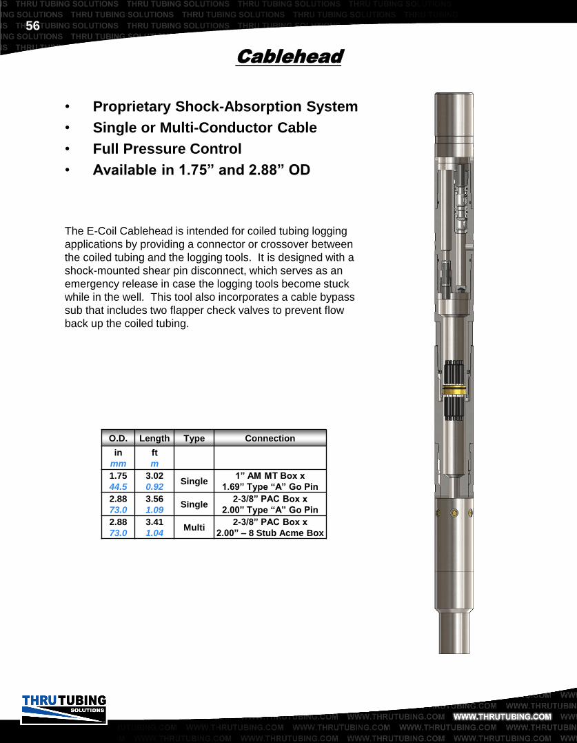
Cablehead
The E-Coil Cablehead is intended for coiled tubing logging
applications by providing a connector or crossover between
the coiled tubing and the logging tools. It is designed with a
shock-mounted shear pin disconnect, which serves as an
emergency release in case the logging tools become stuck
while in the well. This tool also incorporates a cable bypass
sub that includes two flapper check valves to prevent flow
back up the coiled tubing.
• Proprietary Shock-Absorption System
• Single or Multi-Conductor Cable
• Full Pressure Control
• Available in 1.75” and 2.88” OD
O.D. Length Type Connection
in
mm
ft
m
1.75
44.5
3.02
0.92 Single
1” AM MT Box x
1.69” Type “A” Go Pin
2.88
73.0
3.56
1.09 Single
2-3/8” PAC Box x
2.00” Type “A” Go Pin
2.88
73.0
3.41
1.04 Multi
2-3/8” PAC Box x
2.00” – 8 Stub Acme Box

57
E-Wrench™
• Eliminates Over and Under Torqueing
• Durable Construction
• Features TTS “Jaw Locking System”
• Quality Tested and Inspected
The E-Wrench™ is a portable torque measurement system
which comes complete with a 7” Android tablet ready for use
on location. The E-Wrench™ provides traceability for the
make-up of tubing conveyed bottom hole assemblies to
ensure tools are run according to specifications. Audio and
visual cues indicate when the targeted torque is reached,
preventing over and under torqueing the downhole tools.
The TTS Jaw Locking System enables the E-Wrench™ to
grip the tools securely while making and breaking joints. This
patent pending safety feature allows a single operator to
perform these tasks and reduces the tendency of the
wrenches to reactively bounce off the tool during breakout.
A water tight chamber and vibration isolation grommets keep
the electronics well protected, making the E-Wrench™
suitable for harsh oilfield conditions.