Three Years Operation of Ocean Nutrient Enhancer TAKUMI in ...
6
Three Years Operation of Ocean Nutrient Enhancer TAKUMI in Sagami Bay Kazuyuki Ouchi Ouchi Ocean Consultant, Inc Karuizawa Nagano Pref. Japan ABSTRACT TAKUMI the prototype of Ocean Nutrient Enhancer, which upwells and discharges Deep Ocean Water (DOW) in the euphotic layer and increases a primary production in the sea, was set up in Sagami bay in May 2003. Since then, TAKUMI has been continuously upwelling the DOW of 100,000m3/day from the 200m depth, even in the case of rough sea condition. In this paper, the design concept and three years operation experience of TAKUMI is reported briefly. It seems that TAKUMI is the world first successful device for artificial upwelling and increasing primary production in the real sea. KEY WORDS: Deep Ocean Water; Primary Production; Upwelling; Floating Structure; Riser Pipe; Density Current INTRODUCTION To increase a primary production in the sea, Upwelling and discharging a Deep Ocean Water (DOW) which has very rich nutrient salts into the euphotic surface layer has been proposed by many oceanologists as a “Fishing ground of artificial DOW upwelling” (Liu, 1999). Table 1 shows the comparison of the area and the productions in the sea in case of the ocean, the coastal and the upwelling area (Ryther, 1969). The world half fish production is made in the upwelling area which is only 0.1% of the whole sea area, for example, offshore Peru, Canary Islands, etc. But, so far, there are no successful means to make it artificially, because of the problems of the large amount of upwelling DOW, the dilution of nutrient salts in the sea, enduring the rough sea condition, the strength of very long riser pipe for upwelling, etc. Table 1. Production in the Sea MARINO-FORUM 21, a subsidiary of The Fisheries Agency of Japanese Government, established the budget of about USD 6 million and organized the research and development project to create Ocean Nutrient Enhancer (ONE for short) which upwelles and discharges DOW into the euphotic layer to increase primary production of the sea and make a fishing ground. The project started in April 2000, and the term has five years. The device was named TAKUMI. The members and their roles for the project are shown in Table 2. Table 2. Members of TAKUMI Project Member Company Role Ouchi Ocean Consultant Project Manager IHI Marine United Floating Construction JFE Engineering Riser Pipe Nakashima Propeller Pump & Diesel Generator Japan Radio Corporation Electronic Apparatus System Intech Data Processing Zenilite Buoy Light & Signal Mitsubishi Heavy Industries Mooring Design Toa Corporation Set-up Work Mitsui OSK Techno-Trade Operation & Maintenance The featuring technologies of TAKUMI as a prototype of Ocean Nutrient Enhancer are as follows. 1) Density Current Generator; The way of rising DOW and putting it into the euphotic layer. 2) Rotational Flow in Sagami Bay; Choice of the setting point of TAKUMI to avoid the thinning of nutrient salts. Sea Area Primary Production Fish Production Area 10^6 km3 Ratio(%) 10^9 tonC/year Ratio(%) 10^6 ton/year Ratio(%) Ocean 336 90.0 16.3 81.5 0.16 0.07 Coastal 36 9.9 3.6 18.0 120.00 49.97 Upwelling 0.36 0.1 0.19 0.5 120.00 49.97 Total 372 100.0 20.0 100.0 240.16 100.00 3) Submersed Spar Type Floating Structure and Steel Riser Pipe; Configuration of the floating structure and riser pipe to withstand against rough sea condition of the open ocean. 4) Upending; Proper way of setting up in the actual sea. In this paper, the above technology concept is evaluated through three years running operation of TAKUMI in Sagami Bay. ISOPE-2007-OMS-52 Ouchi 6
Transcript of Three Years Operation of Ocean Nutrient Enhancer TAKUMI in ...
Three Years Operation of Ocean Nutrient Enhancer TAKUMI in Sagami Bay
Kazuyuki Ouchi Ouchi Ocean Consultant, Inc
Karuizawa Nagano Pref. Japan
ABSTRACT
TAKUMI the prototype of Ocean Nutrient Enhancer, which upwells and discharges Deep Ocean Water (DOW) in the euphotic layer and increases a primary production in the sea, was set up in Sagami bay in May 2003. Since then, TAKUMI has been continuously upwelling the DOW of 100,000m3/day from the 200m depth, even in the case of rough sea condition. In this paper, the design concept and three years operation experience of TAKUMI is reported briefly. It seems that TAKUMI is the world first successful device for artificial upwelling and increasing primary production in the real sea. KEY WORDS: Deep Ocean Water; Primary Production; Upwelling; Floating Structure; Riser Pipe; Density Current INTRODUCTION
To increase a primary production in the sea, Upwelling and discharging a Deep Ocean Water (DOW) which has very rich nutrient salts into the euphotic surface layer has been proposed by many oceanologists as a “Fishing ground of artificial DOW upwelling” (Liu, 1999). Table 1 shows the comparison of the area and the productions in the sea in case of the ocean, the coastal and the upwelling area (Ryther, 1969). The world half fish production is made in the upwelling area which is only 0.1% of the whole sea area, for example, offshore Peru, Canary Islands, etc. But, so far, there are no successful means to make it artificially, because of the problems of the large amount of upwelling DOW, the dilution of nutrient salts in the sea, enduring the rough sea condition, the strength of very long riser pipe for upwelling, etc.
Table 1. Production in the Sea
MARINO-FORUM 21, a subsidiary of The Fisheries Agency of Japanese Government, established the budget of about USD 6 million and organized the research and development project to create Ocean Nutrient Enhancer (ONE for short) which upwelles and discharges DOW into the euphotic layer to increase primary production of the sea and make a fishing ground. The project started in April 2000, and the term has five years. The device was named TAKUMI. The members and their roles for the project are shown in Table 2.
Table 2. Members of TAKUMI Project
Member Company Role Ouchi Ocean Consultant Project Manager IHI Marine United Floating Construction JFE Engineering Riser Pipe Nakashima Propeller Pump & Diesel Generator Japan Radio Corporation Electronic Apparatus System Intech Data Processing Zenilite Buoy Light & Signal Mitsubishi Heavy Industries Mooring Design Toa Corporation Set-up Work Mitsui OSK Techno-Trade Operation & Maintenance
The featuring technologies of TAKUMI as a prototype of Ocean
Nutrient Enhancer are as follows. 1) Density Current Generator;
The way of rising DOW and putting it into the euphotic layer. 2) Rotational Flow in Sagami Bay;
Choice of the setting point of TAKUMI to avoid the thinning of nutrient salts. Sea Area Primary Production Fish Production
Area
10^6
km3 Ratio(%)
10^9
tonC/year Ratio(%)
10^6
ton/year Ratio(%)
Ocean 336 90.0 16.3 81.5 0.16 0.07
Coastal 36 9.9 3.6 18.0 120.00 49.97
Upwelling 0.36 0.1 0.19 0.5 120.00 49.97
Total 372 100.0 20.0 100.0 240.16 100.00
3) Submersed Spar Type Floating Structure and Steel Riser Pipe; Configuration of the floating structure and riser pipe to withstand against rough sea condition of the open ocean.
4) Upending; Proper way of setting up in the actual sea.
In this paper, the above technology concept is evaluated through three years running operation of TAKUMI in Sagami Bay.
ISOPE-2007-OMS-52 Ouchi 6
OUTLINE OF TAKUMI The principal particulars of TAKUMI is as follows.
Total Height abt. 213m Maximum Breadth 16.8m Draft (Operation) abt. 205m Draft(Maintenance) abt. 185m Displacement (Operation) abt. 1,700t Diameter of Riser Pipe 1.0m Length of Riser Pipe 175m Diameter of Column 2.5m Diameter of Ring Nozzle 10m Depth of Ring Nozzle abt. 20m
Sunlight
Ocean Nutrient Enhancer
Density Current with Nutrient Salt
Euphotic Zone
Deep Ocean Water
SunlightSunlight
Ocean Nutrient EnhancerOcean Nutrient Enhancer
Density Current with Nutrient SaltDensity Current with Nutrient Salt
Euphotic ZoneEuphotic Zone
Deep Ocean WaterDeep Ocean Water
Knot
20’
35oN
34o40’
139o00’E 20’ 40’
Knot
20’
35oN
34o40’
139o00’E 20’ 40’
Mooring System Single Point Catenary Depth of Mooring abt. 1,000m Diameter of Impeller 2.35m Speed of Impeller abt. 40rpm Output of Diesel Generator (Max.) 115kw DOW Rising Capacity abt. 100,000m3/day Surface Suction Capacity abt. 200,000m3/day Discharge Capacity abt. 300,000m3/day The mission of TAKUMI is to rise up nutrient salts and to let them
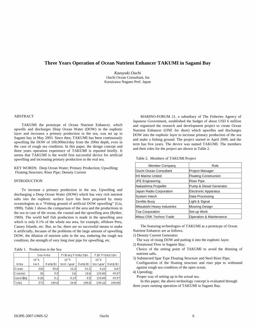
stay in the euphotic region in order to enhance the reaction of photosynthesis. If we only pump up and discharge DOW in a surface euphotic layer the mass of cold and heavy DOW descends back to the deep layer, so that we need some adjustment to avoid DOW descending. The principle of Density Current Generator which was proposed by the authors (Ouchi, et al. 1998) is the solution of letting the DOW stay horizontally in the euphotic layer as a density current. The concept and outline of Density Current Generator which makes average density water by mixing the lower and upper water and discharges it by a special impeller into the same density layer in the stratified water as shown in Fig.1.
Fig .1 Outline of Density Current Generator TAKUMI
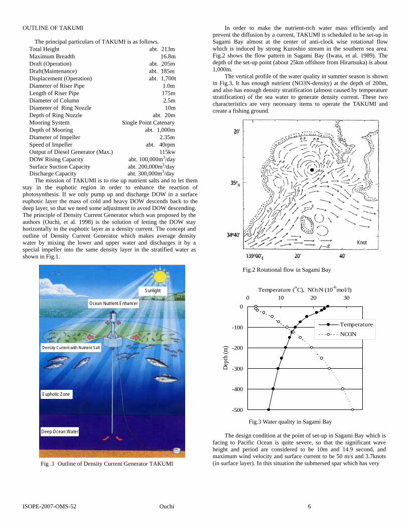
In order to make the nutrient-rich water mass efficiently and prevent the diffusion by a current, TAKUMI is scheduled to be set-up in Sagami Bay almost at the center of anti-clock wise rotational flow which is induced by strong Kuroshio stream in the southern sea area. Fig.2 shows the flow pattern in Sagami Bay (Iwata, et al. 1989). The depth of the set-up point (about 25km offshore from Hirartsuka) is about 1,000m.
The vertical profile of the water quality in summer season is shown in Fig.3. It has enough nutrient (NO3N-density) at the depth of 200m, and also has enough density stratification (almost caused by temperature stratification) of the sea water to generate density current. These two characteristics are very necessary items to operate the TAKUMI and create a fishing ground.
Fig.2 Rotational flow in Sagami Bay
-500
-400
-300
-200
-100
00 10 20 30
Temperature (oC), NO3N (10-6mol/l)
Dept
h (m
)
Temperature
NO3N
Fig.3 Water quality in Sagami Bay
The design condition at the point of set-up in Sagami Bay which is facing to Pacific Ocean is quite severe, so that the significant wave height and period are considered to be 10m and 14.9 second, and maximum wind velocity and surface current to be 50 m/s and 3.7knots (in surface layer). In this situation the submersed spar which has very
ISOPE-2007-OMS-52 Ouchi 6
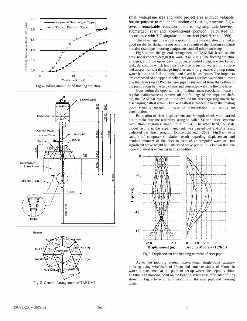
small waterplane area and wind project area is much valuable for the purpose to reduce the motion of floating structure. Fig.4 reveals remarkable reduction of the rolling amplitude between submerged spar and conventional pontoon, calculated in accordance with 3-D singular point method (Nojiri, et al. 1980).
Roll
Ampl
itude
/Wav
e Amp
litud
e (de
g/m)
Proposed Submerged Type
Typical Pontoon Type
The advantage of very little motion of the floating structure makes good results for designing not only the strength of the floating structure but also riser pipe, mooring equipments, and all other outfittings.
Fig.5 shows the general arrangement of TAKUMI based on the provisional concept design (Ogiwara, et al. 2001). The floating structure arranges, from the upper deck to down, a control room, a water ballast tank, the column which has the sluice pipe of suction water from surface and access trunk, a discharge impeller and a ring nozzle, a pump room,
MaintenPum
Moorin
ISOPE-20
05
10
15
20
25
0.
0.
0.
0.
0.2.5
2.0
1.5
1.0
0.5
0.0
0.000 5 10 15 20Wave Period (s)
water ballast and fuel oil tanks, and fixed ballast space. The impellers are composed of an upper impeller that draws surface water and a lower one that draws up DOW. The riser pipe is suspended from the bottom of the pump room by the two chains and connected with the flexible hose.
B
ancp Ro
g C
Flex
07-O
Fig.4 Rolling amplitude of floating structure
Dep
th (m
)
0
-40
0
- 20
- 60
0 2.0-2.0 1.0 2.00 3.0Displacement (m) Bending M oment (106Nm)
-8
1
1
Dep
th (m
)
0
0
0
- 20
- 60
Dep
th (m
)
0
0
0
- 20
- 60
0 2.0-2.0 1.0 2.00 3.0Displacement (m) Bending M oment (106Nm)
0 2.0-2.0 1.0 2.00 3.0Displacement (m) Bending M oment (106Nm)
-4-4
-8-8
11
11
Considering the opportunities of maintenance, especially in case of regular maintenance to remove off bio-foulings of the impeller, shaft, etc, the TAKUMI rises up to the level of the discharge ring nozzle by discharging ballast water. The fixed ballast is needed to keep the floating body standing upright in case of transportation for setting up construction.
Control Room 80
00
6000 45
00
Estimation of riser displacement and strength check were carried out to make sure the reliability, using so called Marine Riser Dynamic Simulation Program (Kitakoji, et al. 1994). The other hand, the scale model testing in the experiment tank was carried out and this result endorsed the above program (Kobayashi, et.al, 2002). Fig.6 shows a sample of computer simulation result regarding displacement and bending moment of the riser in case of an irregular wave of 10m significant wave height and 10second wave period. It is known that one node vibration is occurring in this condition.
As to the mooring system, conventional single-point catenary mooring using wire/chain of 56mm and concrete sinker of 80tons in water is considered at the point of set-up where the depth is about 1,000m. The mooring point on the floating structure is off-center of it as shown in Fig.5. to avoid an interaction of the riser pipe and mooring chain.
ottom
Pump Rm
7391
Operation Draft
e
Suction MouthSluice Pipe
BrackePumppp
Access Trunk
om
hain
ible
Rise
r Pipe
WB 3500
20
000
2925
5 13
500
500
7500
30
00 1500
6000
1500 255
2000
00
16800
Fig.6 Displacement and bending moment of riser pipe
Fig. 5 General Arrangement of TAKUMI
MS-52 Ouchi 6
Setting up operation of TAKUMI is very difficult at the open ocean such as Sagami Bay because the working ship and barge cannot work continuously owing to the high wave and strong ship motion. So that the pre-fabrication and the elimination of the onsite work such as welding fabrication etc. is highly recommended to keep the safety, reliability, and cost effectiveness for the setting up operation.
An upending, the free fall of horizontally laying riser pipe whose end is supported, and instantly making the riser pipe vertical pendant, seems to be the key technology for the setting up operation. In order to know the possibility of upending of pre-fabricated long riser pipe of 200m, a study to find the way of upending was carried out by using computer simulation (Morikawa, et al. 1992). The acceptable case which is small deflection and weak bending stress was found. From the results of such simulations, it was known that the upending is possible if the pipe is fitted with some floaters in proper position. as shown in Fig.7.
There are no upending experiences of such a long steel pipe whose inner space is filled with water. The confirmation tank test of upending using a scale model is needed to make the setting up plan for the safety operation, anyway.
OPERATION OF
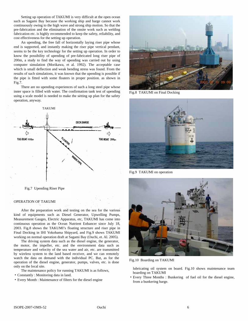
After the prekind of equipmeMeasurement Gaucontinuous operat2003. Fig.8 showFinal Docking in working on norma
The driving the motor, the itemperature and vby wireless systewatch the data ooperation of the donly on the local s
The maintena・Constantly : Mo・Every Month : M
Fig.8 TAKUMI on Final Docking
Fig.7 Upe
ISOPE-2007-OMS
TAKUMI
TAKUMI
paration work and testing on the sea for the various nts such as Diesel Generator, Upwelling Pumps, ges, Electric Apparatus, etc, TAKUMI has come into ion as the Ocean Nutrient Enhancer since July 18, s the TAKUMI’s floating structure and riser pipe in IHI Yokohama Shipyard, and Fig.9 shows TAKUMI l operation draft at Sagami Bay (Ouchi, et. Al. 2005). system data such as the diesel engine, the generator, mpeller, etc. and the environment data such as elocity of the sea water and air, etc. are transmitted
m to the land based receiver, and we can remotely n demand with the individual PC. But, as for the iesel engine, generator, pumps, valves, etc. is done ite. nce policy for running TAKUMI is as follows, nitoring data in land. aintenance of filters for the diesel engine
Fig.9 TAKUMI on operation
nding Riser Pipe
Fig.10 Boarding on TAKUMI
lubricating oil system on board. Fig.10 shows maintenance team boarding on TAKUMI
・Every Three Months : Bunkering of fuel oil for the diesel engine, from a bunkering barge.
-52 Ouchi 6
・Every Year: Inspection and maintenance for underwater apparatuses such as impeller, submerged motor, flexible joint, etc. by lifting up
TAKUMI discharging the water ballast. TAKUMI has been working more than three years since July 2003
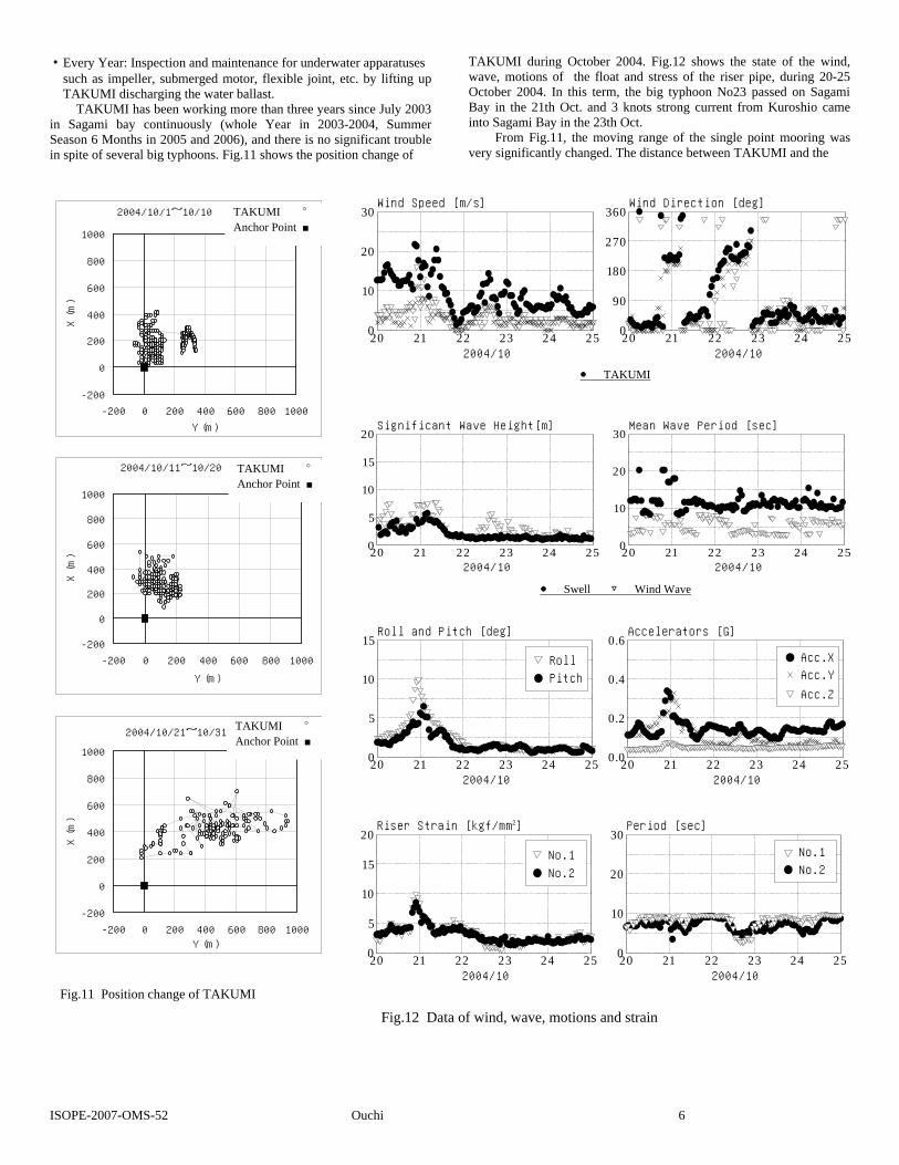
in Sagami bay continuously (whole Year in 2003-2004, Summer Season 6 Months in 2005 and 2006), and there is no significant trouble in spite of several big typhoons. Fig.11 shows the position change of
TAKUMI during October 2004. Fig.12 shows the state of the wind, wave, motions of the float and stress of the riser pipe, during 20-25 October 2004. In this term, the big typhoon No23 passed on Sagami Bay in the 21th Oct. and 3 knots strong current from Kuroshio came into Sagami Bay in the 23th Oct.
From Fig.11, the moving range of the single point mooring was very significantly changed. The distance between TAKUMI and the
20 21 22 23 24 250
5
10
15
20
20 21 22 23 24 250
10
20
30
2004/10
Significant Wave Height[m]
2004/10
Sw
Wi
Mean Wave Period [sec]
20 21 22 23 24 250
10
20
30
20 21 22 23 24 250
90
180
270
360
2004/10
Wind Speed [m/s]
2004/10
TA
MI
TS
Wind Direction [deg]2004/10/1~10/10
-200
0
200
400
600
800
1000
-200 0 200 400 600 800 1000
Y (m)
X (m)
「拓海」
アンカー点
2004/10/11~10/20
-200
0
200
400
600
800
1000
-200 0 200 400 600 800 1000
Y (m)
X (m)
「拓海」
アンカー点
2004/10/21~10/31
-200
0
200
400
600
800
1000
-200 0 200 400 600 800 1000Y (m)
X (m)
「拓海」
アンカー点
20 21 22 230
5
10
15
2004/10
Roll and Pitch [deg]
20 21 22 230
5
10
15
20
2004/10
Riser Strain [kgf/mm2]
TAKUMI ○
Anchor Point ■
TAKUMI ○
Anchor Point ■
TAKUMI ○
Anchor Point ■
Fig.11 Position change of TAKUMI
Fig.12 Data of wind, wav
● TAKUMI
ISOPE-2007-OMS-52 Ouchi
● Swell ▽ Wind Wave
24 25 20 21 22 23 24 250.0
0.2
0.4
0.6
2004/10
Acc.X
Acc.Y
Acc.Z
Accelerators [G]
Pitch
Roll
24 25 20 21 22 23 24 250
10
20
30
2004/10
No.1
No.2
Period [sec]
No.2
No.1
e, motions and strain
6
anchor point which is usually about 200-400m is almost 1,000m because of rough sea and strong current condition.
From Fig.12, the rolling motion of TAKUMI was less than 10°in case of about 8m significant wave height and 18 second wave period in the 21th Oct. It is almost same order which we estimated as shown in Fig.4. As for the strain of the riser pipe of about 100m depth on the same time, the stress level of less than 10kgf/mm2 was observed. It agreed with the riser pipe design.
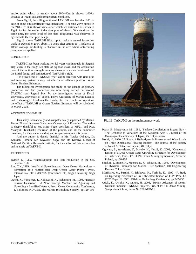
Fig.13 shows TAKUMI lifted up to make a annual inspection work in December 2004, about 1.5 years after setting-up. Thickness of 10mm average bio-fouling is observed in the area where anti-fouling paint was not applied. CONCLUSION
TAKUMI has been working for 3.5 years continuously in Sagami Bay, even in the rough sea state of typhoon class, and the acquisition data of the motion, strength, moving characteristics, etc. endorsed that the initial design and estimation of TAKUMI is right.
It is proved that a TAKUMI type floating structure with riser pipe and mooring system is very suitable for an offshore platform as an Ocean Nutrient Enhancer.
The biological investigation and study on the change of primary production and fish production are now being carried out around TAKUMI and Sagami Bay, by the investigation team of Kochi University, University of Tokyo, Tokyo University of Marine Science and Technology, Hiroshima University, etc. The conclusion report on the effect of TAKUMI as Ocean Nutrient Enhancer will be scheduled in March 2008. ACKNOWLEDGEMENT
This study is financially and sympathetically supported by Marino-Forum 21 and Japanese Government’s Agency of Fisheries. The author is deeply thankful to Mr. Shiro Yuge; president of MF21, and Prof. Masayuki Takahashi; chairman of the project, and all the committee members, for their understanding and support to submit this paper.
And the author is deeply thankful to Mr. Yutaka Ohkawa, Dr. Kenkichi Tamura, Mr. Kiyokazu Yago, and Dr. Katsuya Maeda of National Maritime Research Institute, for their effort of data acquisition and analysis on TAKUMI. REFERENCES Ryther, J., 1969, “Photosynthesis and Fish Production in the Sea,
Science, 166 Liu, C.K.,1999, “Artificial Upwelling and Open Ocean Mariculture –
Formation of a Nutrient-rich Deep Ocean Water Plume”, Proc., International OTEC/DOWA Conference ’99, Saga University, Saga Japan
Ouchi, K., Yamatogi, T., Kobayashi, K., Nakamura, M., 1998, “Density Current Generator – A New Concept Machine for Agitating and Upwelling a Stratified Water -, Proc., Ocean Community Conference, 1, Baltimore MD USA, The Marine Technology Society, pp.129-136
Fig.13 TAKUMI on the maintenance work
Iwata, S., Matsuyama, M., 1989, “Surface Circulation in Sagami Bay – The Response to Variations of the Kuroshio Axis -, Journal of the Oceanographical Society of Japan, 45, Tokyo Japan
Nojiri, N., 1980, “A Study of Hydrodynamic Pressures and Wave Loads on Three-Dimensional Floating Bodies”, The Journal of the Society of Naval Architects of Japan, 148, Tokyo
Ogiwara, S., Awashima, Y., Miyabe, H., Ouchi, K., 2001, “Conceptual Design of a Deep Ocean Water Upwelling Structure for Development of Fisheries”, Proc., 4th ISOPE Ocean Mining Symposium, Szczecin Poland, pp150-157
Kitakoji,Y., Inoue, K., Matsunaga, K., Ohkusu, M., 1994, “Development of Dynamic Simulator for Marine Riser System”, IHI Engineering Review, Tokyo Japan
Morikawa, M., Suzuki, H., Ishikawa, K., Yoshida, K., 1992 “A Study on Upending Procedure of Pre-Fabricated Tendon of TLP” Proc. Of OTC, Paper No.6901, Offshore Technology Conference, pp.247-255
Ouchi, K., Otsuka, K., Omura, H., 2005, “Recent Advances of Ocean Nutrient Enhancer TAKUMI Project”, Pric. of ISOPE Ocean Mining Symposium, China, Paper No.2005-KO-01
ISOPE-2007-OMS-52 Ouchi 6