A Practical Three-dimensional Dosimetry System for Radiation Therapy
Travis J. McCaw
Medical Radiation Research Center
Department of Medical Physics
University of Wisconsin, Madison, WI
NCCAAPM 2013 Fall Meeting
10 October 2013
Three-dimensional dosimetry of small fields
MedicalRadiationResearchCenter
� 3D dosimeters
� Fricke gel
� Polymer gel
� PRESAGE®
� Small field dosimetry
� Alfonso formalism
� Applications for 3D dosimetry
� Radiochromic film stack dosimeter
2
Outline

� Radiation-induced conversion of ferrous ions to ferric ions
� Different NMR relaxation rates permit MR readout
� Incorporate ferrous sulphate solution into organic gel matrix to
measure spatial dose distribution
� Postexposure ionic diffusion introduces error
� High electrical conductivity strongly attenuates RF pulses during MR readout
3
Fricke gel• 3D
dosimeters
• Small field
dosimetry
• FSD
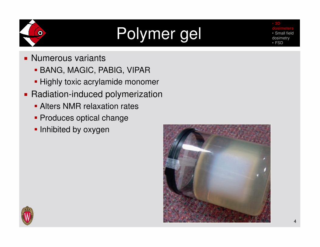
� Numerous variants
� BANG, MAGIC, PABIG, VIPAR
� Highly toxic acrylamide monomer
� Radiation-induced polymerization
� Alters NMR relaxation rates
� Produces optical change
� Inhibited by oxygen
4
Polymer gel• 3D
dosimeters
• Small field
dosimetry
• FSD
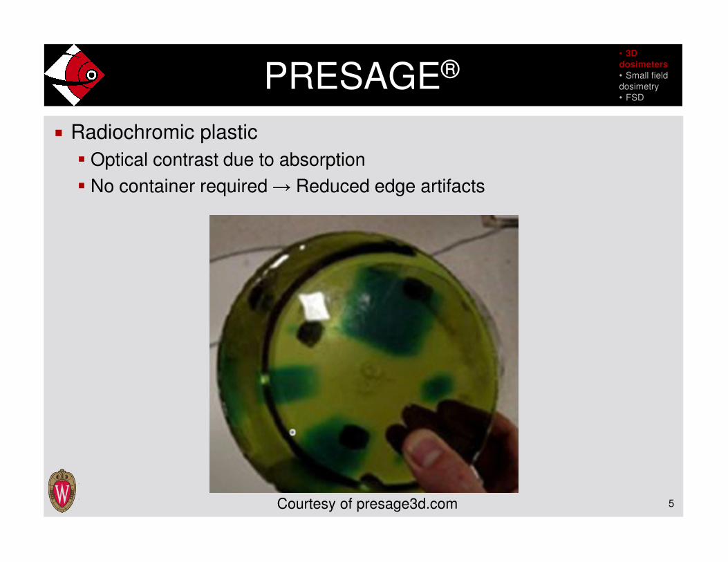
� Radiochromic plastic
� Optical contrast due to absorption
� No container required → Reduced edge artifacts
5
PRESAGE®
Courtesy of presage3d.com
• 3D
dosimeters
• Small field
dosimetry
• FSD

� How small is small?
� Field size
� Detector size
� Range of secondary electrons
� Source occlusion
� Breakdown of FWHM field size definition
� Reduced source output results in field size overestimation
� Loss of CPE with relatively large electron ranges
� Use of cavity theory
� Charged particle fluence perturbation by detector
� Dependent on energy and field size
6
Problems with small field dosimetry
I. J. Das, G. X. Ding, and A. Ahnesjö, Med. Phys. 35, 206-215 (2008).
• 3D
dosimeters
• Small field
dosimetry
• FSD
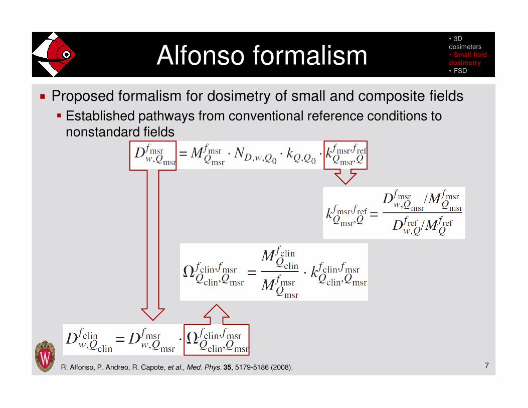
� Proposed formalism for dosimetry of small and composite fields
� Established pathways from conventional reference conditions to nonstandard fields
7
Alfonso formalism
R. Alfonso, P. Andreo, R. Capote, et al., Med. Phys. 35, 5179-5186 (2008).
• 3D
dosimeters
• Small field
dosimetry
• FSD

� Compared OF and profiles measured with gel, PinPoint chamber,
diode array and diamond detector
� Pros
� Tissue equivalence
� No fluence perturbation (gel is phantom and dosimeter)
� Good resolution
� No positioning errors due to measurement of full distribution
� Cons
� High uncertainty in smaller voxels
� Improves with larger voxels, but volume averaging increases
� Inconsistencies in preparation
� Differences in calibration and experimental geometries
8
Small-field polymer gel dosimetry
E. Pappas, I. Seimenis, A. Angelopoulos, et al., Phys. Med. Biol. 46, 783-797 (2001).E. Pappas, L. Petrokokkinos, A. Angelopoulos, et al., Med. Phys. 32, 1513-1520 (2005).E. Pappas, T. G. Maris, A. Papadakis, et al., Med. Phys. 33, 3700-3710 (2006).E. Pappas, T. G. Maris, F. Zacharopoulou, et al., Med. Phys. 35, 4640-4648 (2008).
• 3D
dosimeters
• Small field
dosimetry
• FSD

9
Profile measurements
E. Pappas, I. Seimenis, A. Angelopoulos, et al., Phys. Med. Biol. 46, 783-797 (2001).E. Pappas, L. Petrokokkinos, A. Angelopoulos, et al., Med. Phys. 32, 1513-1520 (2005).E. Pappas, T. G. Maris, A. Papadakis, et al., Med. Phys. 33, 3700-3710 (2006).E. Pappas, T. G. Maris, F. Zacharopoulou, et al., Med. Phys. 35, 4640-4648 (2008).
• 3D
dosimeters
• Small field
dosimetry
• FSD

10
Output factor measurements
E. Pantelis, C. Antypas, L. Petrokokkinos, et al., Med. Phys. 35, 2312-2320 (2008).E. Pantelis, A. Moutsatsos, K. Zourari, et al., Med. Phys. 37, 2369-2379 (2010).E. Pantelis, A. Moutsatsos, K. Zourari, et al., Med. Phys. 39, 4875-4885 (2012).
• 3D
dosimeters
• Small field
dosimetry
• FSD

11
Film stack dosimetry• 3D
dosimeters
• Small field
dosimetry
• FSD
� Previous investigations of radiochromic film stack dosimetry[1,2]
� Considered several characteristics:
� Water equivalence
� Energy dependence[3]
� Orientation dependence[4]
� Measurement uncertainty
1. S. Chiu-Tsao, T. L. Duckworth, N. S. Patel, et al., Med. Phys. 31, 201-207 (2004).2. S. Chiu-Tsao and M. F. Chan, Med. Phys. 36, 2074-2083 (2009).3. J. G. H. Sutherland and D. W. O. Rogers, Med. Phys. 37, 1110-1116 (2010).4. N. Suchowerska, P. Hoban, M. Butson, et al., Phys. Med. Biol. 46, 1391-1397 (2001).
12
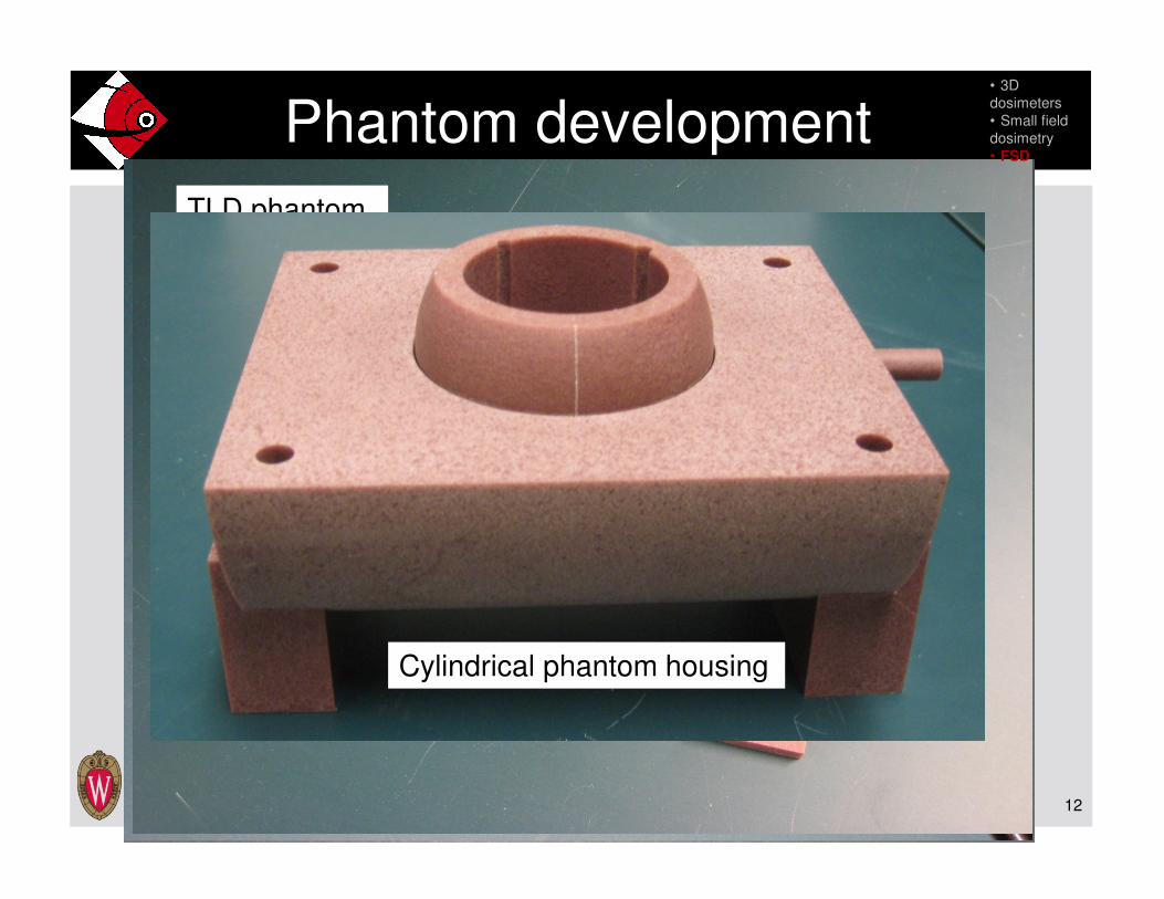
Phantom development
Film stack dosimeter phantomFilm and ionization chamber phantom
TLD phantom
Cylindrical phantom housing
• 3D
dosimeters
• Small field
dosimetry
• FSD

13
Film stack dosimeter• 3D
dosimeters
• Small field
dosimetry
• FSD
� Circular films with semicircular tabs on the outer diameter
� Tabs fix azimuthal orientation of films
� Films were laser cut[1] with a tolerance of 0.08 mm
� Positioning uncertainty within phantom of 0.19 mm
� 1 mm-thick Virtual Water™[2] spacers interleaved between films
� Reduces air gap created by film burr
� Film stack dosimeter specifications:
� 3.8 cm diameter
� 2.7 cm height
� 22 films and 21 spacers
� 0.02 mm air gaps
1. Laserage Technology Corporation®, Waukegan, IL2. Med-Cal, Inc., Verona, WI

� MCNP simulations used 6 MV point source
� Spectrum from BEAMnrc model of UWMRRC linac
� Orientation dependence
� Simulated dose to cylindrical volume at center of film stack
� Rotated source about longitudinal axis of tally volume
� Investigated the impact of air gap size
� Water equivalence
� Simulated PDD in a cylindrical water phantom for comparison with film stack dosimeter measurements
14
FSD characterization: Simulations• 3D
dosimeters
• Small field
dosimetry
• FSD
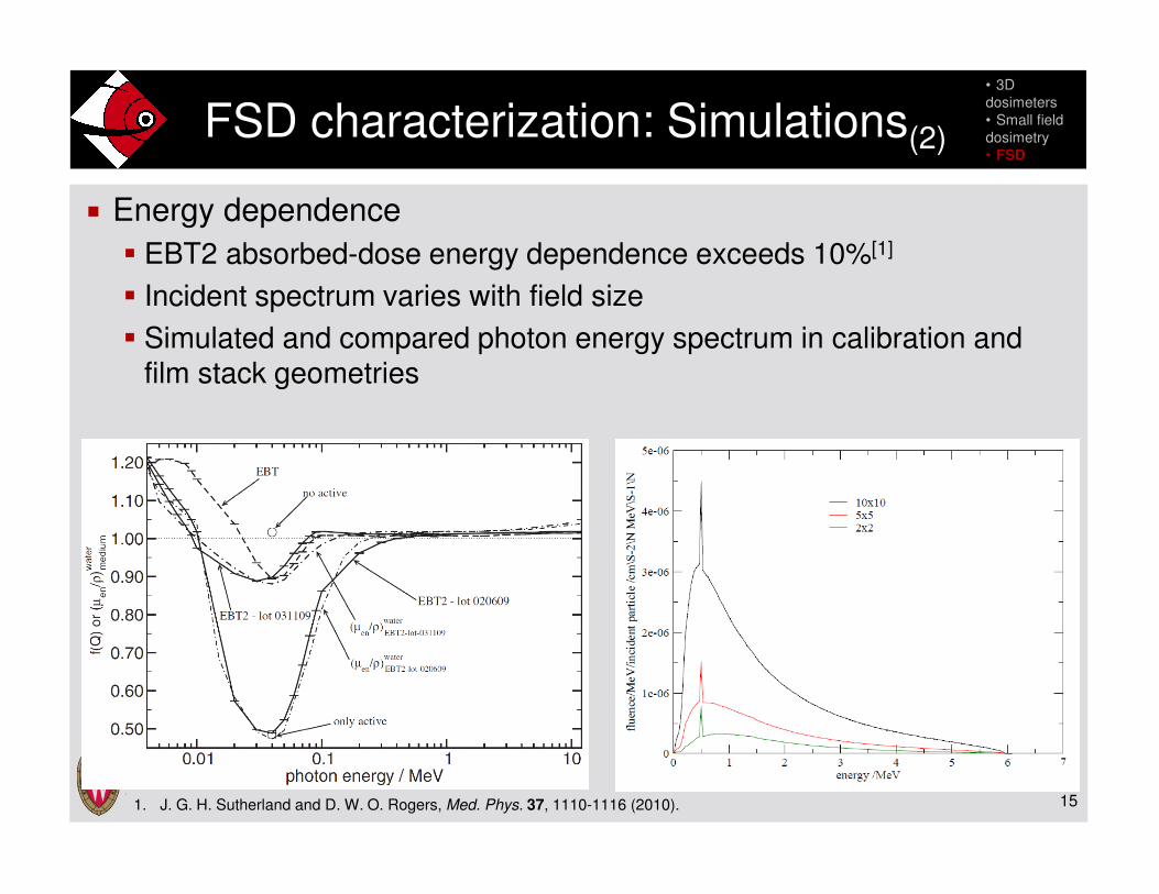
� Energy dependence
� EBT2 absorbed-dose energy dependence exceeds 10%[1]
� Incident spectrum varies with field size
� Simulated and compared photon energy spectrum in calibration and film stack geometries
15
FSD characterization: Simulations(2)
• 3D
dosimeters
• Small field
dosimetry
• FSD
1. J. G. H. Sutherland and D. W. O. Rogers, Med. Phys. 37, 1110-1116 (2010).
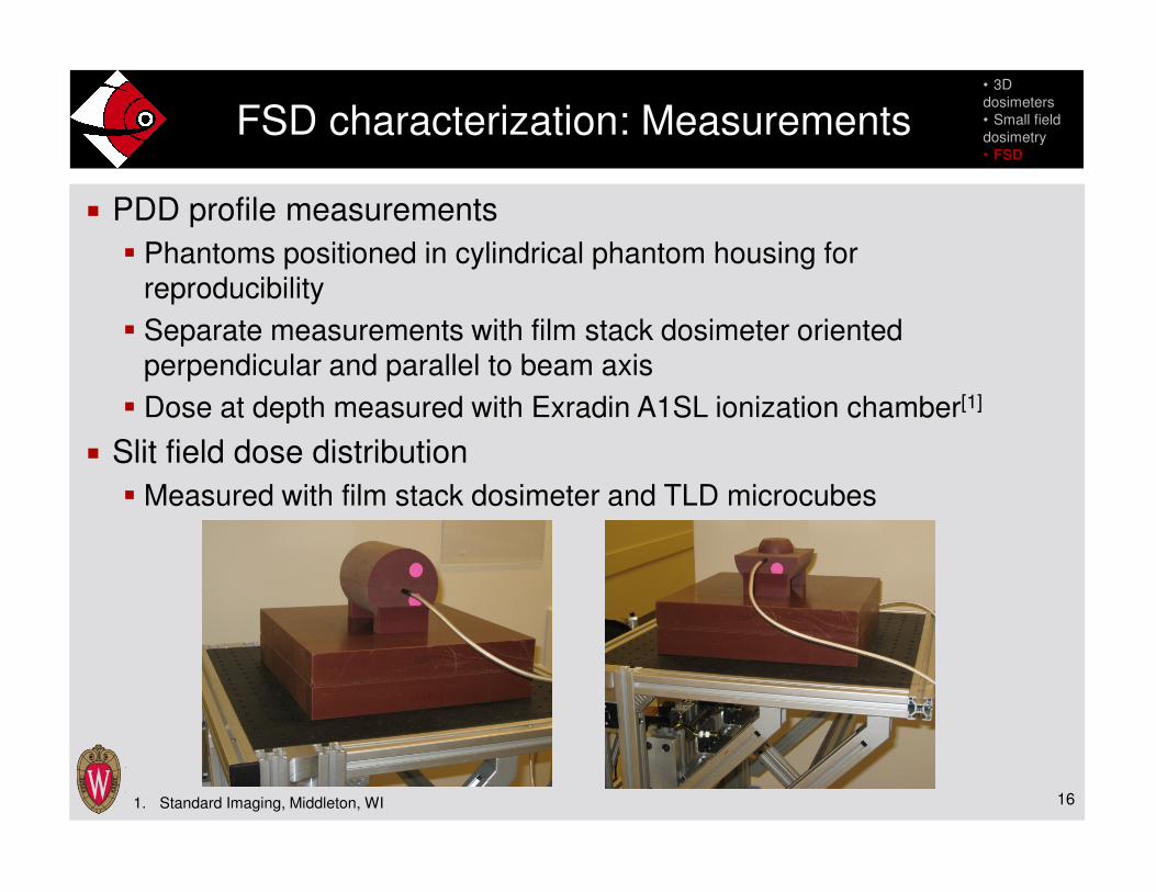
� PDD profile measurements
� Phantoms positioned in cylindrical phantom housing for reproducibility
� Separate measurements with film stack dosimeter oriented perpendicular and parallel to beam axis
� Dose at depth measured with Exradin A1SL ionization chamber[1]
� Slit field dose distribution
� Measured with film stack dosimeter and TLD microcubes
16
FSD characterization: Measurements• 3D
dosimeters
• Small field
dosimetry
• FSD
1. Standard Imaging, Middleton, WI

17
Film dosimetry• 3D
dosimeters
• Small field
dosimetry
• FSD
� Films were read with Epson® Expression® 10000XL flatbed scanner[1]
� Immediately before and seven days after exposure
� Masks center films in scan bed and reduce extra-film scatter
� Elevated films to eliminate Newton’s ring artifacts
� Monitored scanner stability with neutral-density filters
1. Epson America, Long Beach, CA

� Orientation dependence less than 1.5% for smaller air gaps
� Under-response of 3% at parallel incidence for larger air gaps
� Statistical uncertainty of 0.5% (k = 1)
18
Results: Orientation dependence
T. McCaw, J. Micka, and L. DeWerd, Med. Phys. 40, 223 (2013)
• 3D
dosimeters
• Small field
dosimetry
• FSD

� Simulated PDD profile converted to dose using ion chamber
measurement
� Film stack measurements normalized to max simulated dose
� Measurements and simulation agree within 2%
19
Results: Water equivalence• 3D
dosimeters
• Small field
dosimetry
• FSD
T. McCaw, J. Micka, and L. DeWerd, Med. Phys. 40, 223 (2013)

� Visibly different photon energy spectra in calibration and film stack
geometries
� Resulting absorbed-dose energy response less than 0.1%
20
Results: Energy dependence• 3D
dosimeters
• Small field
dosimetry
• FSD

21
Slit field measurement geometry• 3D
dosimeters
• Small field
dosimetry
• FSD
0
z
x
y
22
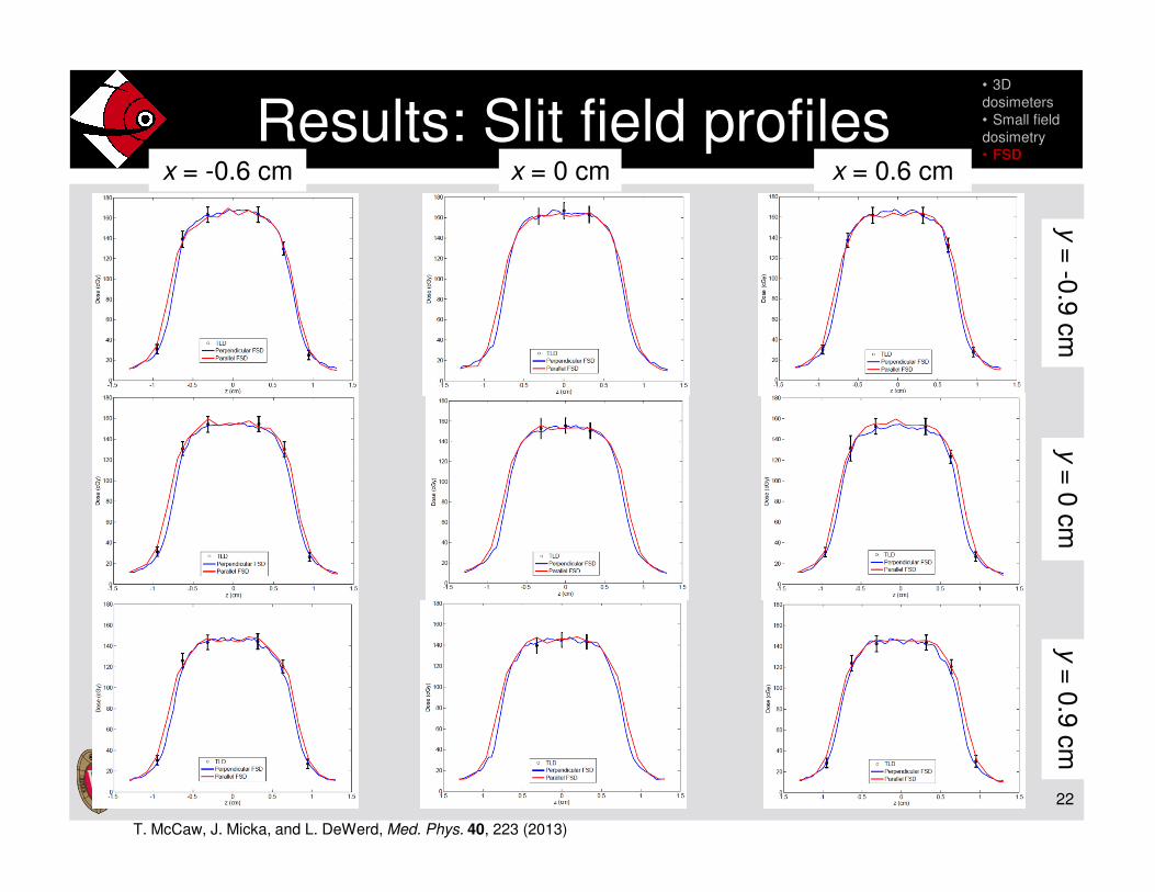
Results: Slit field profiles• 3D
dosimeters
• Small field
dosimetry
• FSD
x = 0.6 cmx = -0.6 cm x = 0 cm
y=
-0.9
cm
y=
0.9
cm
y=
0 c
m
T. McCaw, J. Micka, and L. DeWerd, Med. Phys. 40, 223 (2013)
23
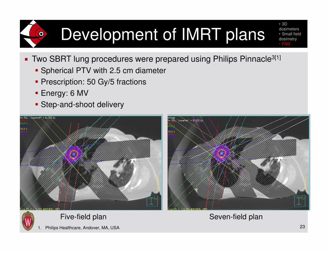
� Two SBRT lung procedures were prepared using Philips Pinnacle3[1]
� Spherical PTV with 2.5 cm diameter
� Prescription: 50 Gy/5 fractions
� Energy: 6 MV
� Step-and-shoot delivery
Development of IMRT plans
Five-field plan Seven-field plan
1. Philips Healthcare, Andover, MA, USA
• 3D
dosimeters
• Small field
dosimetry
• FSD
24
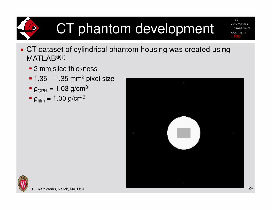
� CT dataset of cylindrical phantom housing was created using
MATLAB®[1]
� 2 mm slice thickness
� 1.35 1.35 mm2 pixel size
� ρCPH = 1.03 g/cm3
� ρfilm = 1.00 g/cm3
CT phantom development
1. MathWorks, Natick, MA, USA
• 3D
dosimeters
• Small field
dosimetry
• FSD
25
� Reduced prescribed MU by a factor of 5 for a dose at isocenter
of ~2-3 Gy
� Initial DQA of plans performed with Delta4 diode array detector[1]
� 99% passing rate using gamma criteria[2] of 3% and 3 mm
� Two measurements of each plan were made with the film stack
dosimeter
� Seven-field plan also measured with TLD phantom
� Compared measured and calculated dose distributions
� 1 1 1 mm3 calculated dose grid resolution
IMRT DQA measurements
1. ScandiDos, Uppsala, Sweden2. D. A. Low, W. B. Harms, S. Mutic, and J. A. Purdy, Med. Phys. 25, 656-661 (1998)
• 3D
dosimeters
• Small field
dosimetry
• FSD

26
Seven-field results
… Exposure 1
__ Pinnacle
Transverse plane
Sagittal plane
Coronal plane
• 3D
dosimeters
• Small field
dosimetry
• FSD
T. McCaw, J. Micka, and L. DeWerd, Med. Phys. Int. 1, 242 (2013)

� Gamma analysis of film stack measurements using criteria of
3%/3 mm
� Greater than 97% agreement with calculation
� Consistent with TLD and Delta4 measurements
� Repeatability
� Five-field plan: 96% of points agree within 5%
� Seven-field plan: 93% of points agree within 5%
� Overall film measurement uncertainty is 5.3% (k = 2)
27
IMRT QA analysis• 3D
dosimeters
• Small field
dosimetry
• FSD
T. McCaw, J. Micka, and L. DeWerd, Med. Phys. Int. 1, 242 (2013)
� Polymer gel has strengths and weaknesses for small field
dosimetry
� Tissue equivalence, good resolution, no fluence perturbation
� Poor reproducibility, high uncertainty
� Radiochromic film stack dosimeter provides an alternative 3D
dosimeter
� Maintains strengths of gel dosimeter
� Improved reproducibility and uncertainty
28
Conclusions

� Dr. Larry DeWerd
� John Micka
� Ben Palmer
� Cliff Hammer
� Scott Johnson (Med-Cal, Inc.)
� Dr. Jennifer Smilowitz
� UWMRRC students and staff
� UWADCL customers for their continued support of our research
program
29
Acknowledgements