
Three-Dimensional Digital Colour Camera - Intech
16
14 Three-Dimensional Digital Colour Camera Yung-Sheng Chen 1 , I-Cheng Chang 2 , Bor-Tow Chen 3 and Ching-Long Huang 3 1 Department of Electrical Engineering, Yuan Ze University, Chungli, 2 Department of Computer Science and Information Engineering National Dong Hwa University, Hualien, 3 Opto Electronics & Systems Laboratories, Industrial Technology Research Institute, Hsinchu, Taiwan, ROC 1. Introduction Digital colour camera now has been a popular consumer equipment, has widely used in our daily life, and is highly suited for the next generation of cellular phones, personal digital assistants and other portable communication devices. The main applications of digital colour camera are used to take a digital picture for personal use, picture editing and desktop publishing, high-quality printing, and image processing for advanced academic research. The digital picture is a two-dimensional (2D) form with three-colour components (Red, Green, Blue). The most of efforts for a digital camera producer are focusing on the improvements of image compression, image quality, image resolution, and optical/ digital zooming. However, consider the wide field of computer vision, the depth for a captured object may be another very useful and helpful information, such as surface measurement, virtual reality, object modelling and animation, it will be valuable if the depth information can be obtained while a picture is being captured. In other words, three-dimensional (3D) imaging devices promise to open a very wide variety of applications, particularly, those involving a need to know the precise 3D shape of the human body, e.g. e-commerce (clothing), medicine (assessment, diagnosis), anthropometry (vehicle design), post- production (virtual actors) and industrial design (workspace design) (Siebert & Marshall, 2000). To achieve this significant function, a novel 3-D digital colour camera has been successfully developed by Industrial Technology Research Institute, Opto Electronics & Systems Laboratories (ITRI-OES), in Taiwan. In this article, the previous works, algorithms, structure of our 3D digital colour camera, and 3D results, will be briefly presented. To obtain 3D information of a given object, the approach may be considered in between a passive scheme and an active scheme. The widely known passive scheme is stereovision, which is useful to measure surfaces with well-defined boundary edges and vertexes. An algorithm to recognize singular points may be used to solve the problem of correspondence between points on both image planes. However the traditional stereoscopic system becomes rather inefficient to measure continuous surfaces, where there are not many reference points. It has also several problems in textural surfaces or in surfaces with lots of discontinuities. Under such an environment, the abundance of reference points can produce Source: Image Processing, Book edited by: Yung-Sheng Chen, ISBN 978-953-307-026-1, pp. 572, December 2009, INTECH, Croatia, downloaded from SCIYO.COM www.intechopen.com
Transcript of Three-Dimensional Digital Colour Camera - Intech

14
Three-Dimensional Digital Colour Camera
Yung-Sheng Chen1, I-Cheng Chang2,
Bor-Tow Chen3 and Ching-Long Huang3 1Department of Electrical Engineering, Yuan Ze University, Chungli,
2Department of Computer Science and Information Engineering
National Dong Hwa University, Hualien, 3Opto Electronics & Systems Laboratories,
Industrial Technology Research Institute, Hsinchu,
Taiwan, ROC
1. Introduction
Digital colour camera now has been a popular consumer equipment, has widely used in our
daily life, and is highly suited for the next generation of cellular phones, personal digital
assistants and other portable communication devices. The main applications of digital
colour camera are used to take a digital picture for personal use, picture editing and desktop
publishing, high-quality printing, and image processing for advanced academic research.
The digital picture is a two-dimensional (2D) form with three-colour components (Red,
Green, Blue). The most of efforts for a digital camera producer are focusing on the
improvements of image compression, image quality, image resolution, and optical/ digital
zooming. However, consider the wide field of computer vision, the depth for a captured
object may be another very useful and helpful information, such as surface measurement,
virtual reality, object modelling and animation, it will be valuable if the depth information
can be obtained while a picture is being captured. In other words, three-dimensional (3D)
imaging devices promise to open a very wide variety of applications, particularly, those
involving a need to know the precise 3D shape of the human body, e.g. e-commerce
(clothing), medicine (assessment, diagnosis), anthropometry (vehicle design), post-
production (virtual actors) and industrial design (workspace design) (Siebert & Marshall,
2000). To achieve this significant function, a novel 3-D digital colour camera has been
successfully developed by Industrial Technology Research Institute, Opto Electronics &
Systems Laboratories (ITRI-OES), in Taiwan. In this article, the previous works, algorithms,
structure of our 3D digital colour camera, and 3D results, will be briefly presented.
To obtain 3D information of a given object, the approach may be considered in between a
passive scheme and an active scheme. The widely known passive scheme is stereovision,
which is useful to measure surfaces with well-defined boundary edges and vertexes. An
algorithm to recognize singular points may be used to solve the problem of correspondence
between points on both image planes. However the traditional stereoscopic system becomes
rather inefficient to measure continuous surfaces, where there are not many reference
points. It has also several problems in textural surfaces or in surfaces with lots of
discontinuities. Under such an environment, the abundance of reference points can produce
Source: Image Processing, Book edited by: Yung-Sheng Chen, ISBN 978-953-307-026-1, pp. 572, December 2009, INTECH, Croatia, downloaded from SCIYO.COM
www.intechopen.com

Image Processing
246
matching mistakes. Thus, an active system based on a structured light concept will be useful
(Siebert & Marshall, 2000; Rocchini et al., 2001; Chen & Chen, 2003). In our 3D camera
system, the constraint that codifies the pattern projected on the surface has been simplified
by using a random speckle pattern, the correspondence problem can be solved by a local
spatial-distance computation scheme (Chen & Chen, 2003) or a so-called compressed image
correlation algorithm (Hart, 1998).
In our original design, the 3D camera system includes a stereoscopic dual-camera setup, a
speckle generator, and a computer capable of high-speed computation. Figure 1(a) shows
the first version of our 3D camera system including two CCD cameras needing a distance of
10 cm between its 2 lenses, and a video projector, where the used random speckle pattern in
Fig. 1(b) is sent from the computer and projected via the video projector on the measuring
object. Each of two cameras takes the snapshot from its own viewpoint, and can do the
simultaneous colour image capturing. A local spatial-distance computation scheme or a
compressed image correlation (CIC) algorithm then finds some specific speckles on the two
camera images. Each of the selected speckles would have its position shown twice, one on
each image. After establishing the statistic correlation of the corresponding vectors on the
two images, the 3D coordinates of the spots on the object surface will be known from the 3D
triangulation.
(a) (b)
Fig. 1. (a) Our original 3D measurement system. (b) The used random speckle pattern, which
is sent from the computer and projected via the video projector.
Not only the traditional stereoscopic systems (Siebert & Marshall, 2000; Rocchini et al., 2001)
but also the above mentioned system (Chen & Chen, 2003) are all not easy to be used
friendly and popularly due to large system scale, complicated operations, and
expensiveness. Hence, to achieve the valuable features (portable, easy operation,
inexpensiveness) as possessed by a 2D digital camera, we present a novel design which can
be applied to a commercial digital still camera (DSC), and make the 2D camera be able to
capture 3D information (Chang et al., 2002). The proposed 3D hand-held camera (the second
version of our 3D measurement system) contains three main components: a commercial
DSC (Nikon D1 camera body), a patented three-hole aperture lens (Huang, 2001; Chen &
Huang, 2002), and a flash. The flash projects the speckle pattern onto the object and the
camera captures a single snapshot at the same time. Accordingly, our 3-D hand-held camera
www.intechopen.com

Three-Dimensional Digital Colour Camera
247
design integrating together the speckle generating projector and the colour digital camera
makes the system be able to move around freely when taking pictures.
The rest of this article is organized as follows. Section 2 reviews briefly our previous works.
Section 3 presents algorithms for improving 3D measurements. The structure of our novel
3D camera is described in Section 4. Finally a conclusion is given in Section 5. Because the
found 3D information should be visualized for the use, all the 3D results are currently
manipulated and displayed by our TriD system (TriD, 2002), which is a powerful and
versatile modelling tool for 3D captured data, developed by ITRI-OES in Taiwan.
2. Previous works
Our original 3D measurement system shown in Fig. 1(a) includes two CCD cameras and a
video projector, where the used random speckle pattern shown in Fig. 1(b) is sent from the
computer and projected via the video projector onto the object to be measured. In this
system, to solve the correspondence problem of measuring a 3D surface, the random speckle
pattern was adopted to simplify the constraint that codifies the pattern projected on the
surface and the technique of spatial distance computation was applied to find the
correspondence vector (or the correlation vector used in the later of this article).
To effectively perform the correspondence vector finding task, the binarization for the
captured image is used in our 3D system developments. The following is our adaptive
thresholding method for binarization.
Let a grey block image be defined as G having the size of m m× . The correspondence
problem is based on the local matching between two binary block images. Therefore it is
important to determine the thresholding value TH, for obtaining the binary block image B.
To overcome the uneven-brightness and out-of-focus problem arising from the lighting
environment and different CCD cameras, the brightness equalization and image
binarization are used. Let 2m be the total number of pixels of a block image, and cdf(z), z =
0~255 (the grey value index, where each pixel is quantized to a 8-bit data) be the cumulative
distribution function of G, then a thresholding controlled by the percentile p = 0~100% is
defined
{ }2| ( )p p pTH z cdf z pm= ≈ (1)
Thus for a percentile p each grey block image G will have a thresholding value pTH to
obtain its corresponding binary block image B, and we have
1 if ( , )
( , )0 otherwise
pg x y THB x y
≥⎧= ⎨⎩ (2)
where 1 and 0 denote the nonzero (white) pixel and the zero (black) pixel, respectively. Note
here that the higher the p is, the smaller the data amount having nonzero pixels.
In our previous work, our distance computation approach for finding correspondence
vectors is simply described as follows. Let 0 0,
l
x yB , x0 = 0, s, 2s, …; and y0 = 0, s, 2s, …, be a
binary block image in the left-captured image starting at the location (x0, y0), where s is the
sampling interval from the captured image. The searched block image, 0 0,
r
u vB starting at the
location (u0, v0) in the right-captured image, will be in the range of u0 in [x0- xR , x0+ xR ] and
www.intechopen.com
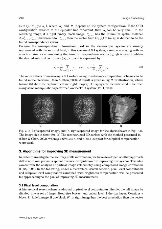
Image Processing
248
v0 in [y0- yR , y0+ yR ], where xR and yR depend on the system configuration. If the CCD
configuration satisfies to the epipolar line constraint, then yR can be very small. In the
searching range, if a right binary block image ,f f
r
u vB has the minimum spatial distance
d(0 0,
l
x yB , ,f f
r
u vB ) between it to 0 0,
l
x yB , then the vector from (x0, y0) to (uf, vf) is defined to be the
found correspondence vector.
Because the corresponding information used in the stereoscopic system are usually
represented with the subpixel level, in this version of 3D system, a simple averaging with an
area A of size w w× containing the found correspondence results (uf, vf)s is used to obtain
the desired subpixel coordinate ( *
fu , *
fv ) and is expressed by
* *
( , ) ( , )
1 1 and
f f f f
f f f f
u v A u v A
u u v vN N∀ ∈ ∀ ∈
= =∑ ∑ (3)
The more details of measuring a 3D surface using this distance computation scheme can be
found in the literature (Chen & Chen, 2003). A result is given in Fig. 2 for illustration, where
(a) and (b) show the captured left and right images; (c) displays the reconstructed 3D surface
along some manipulations performed on the TriD system (TriD, 2000).
(a) (b) (c)
Fig. 2. (a) Left captured image, and (b) right captured image for the object shown in Fig. 1(a).
The image size is 640 480× . (c) The reconstructed 3D surface with the method presented in
(Chen & Chen, 2003), where p = 65%, s = 4, and a 5 5× support for subpixel compensation
were used.
3. Algorithms for improving 3D measurement
In order to investigate the accuracy of 3D information, we have developed another approach
different to our previous spatial distance computation for improving our system. This idea
comes from the analysis of partical image velocimetry using compressed image correlation
(Hart, 1998). In the following, under a hierarchical search scheme, pixel level computation
and subpixel level computation combined with brightness compensation will be presented
for approaching to the goal of improving 3D measurement.
3.1 Pixel level computation
A hierarchical search schem is adopted in pixel level computation. First let the left image be
divided into a set of larger fixed-size blocks, and called level 1 the top layer. Consider a
block 1
lB in left image, if one block 1
rB in right image has the best correlation then the vector
www.intechopen.com

Three-Dimensional Digital Colour Camera
249
1V from the coordinate of 1
lB to that of 1
rB is found. Based on the facility of coarse-to-fine,
the next search is confined to the range indicated by 1V in right image and the execution
time can be further reduced. Hence next, let the block image 1
lB in level 1 be further divided
into four subblocks, this is the level 2. Consider the subblock 2
lB in 1
lB having the same
coordinate, by the vector 1V , the correlation process is further performed only on the
neighboring subblocks centered at the coordinate of 1
rB . The best correlation conducting the
vector 2V from the coordinate of 2
lB to one subblock 2
rB is found. Continue this process, if
the best match is found and ended at level n, then the final vector of best correlation may be
expressed as
1
n
i
i
V V=
=∑ (4)
In order to reduce the computation time of correlation, a so-called correlation error function
for an M N× image is used and defined as follows (Hart, 1998).
( )
( ), , , ,
1 1,
, ,
1 1
M N
m n m i n j m n m i n j
m ni j M N
m n m i n j
m n
I I I I
I I
φ +Δ +Δ +Δ +Δ= =Δ Δ+Δ +Δ= =
+ − −=
+∑∑
∑∑ (5)
This function only uses addition and subtraction, thus the time reduction is expectable. Note
here that the processed images Is are binarized after adaptive thresholding as described in
Section 2, thus the information of Is are only either 1 or 0.
3.2 Subpixel level computation In order to increase the accuracy of the correspondence finding, two schemes are combined
for achieving this purpose. One is grey scale interpolation, the other is brightness
compensation. For grey scale interpolation, a linear scheme is performed on the third layer
of right image. In our study, the block size of the third layer is 8 8× . The processing includes
two steps as follows.
Step 1. Use the pixel grey levels in vertical direction to interpolate the subpixel grey level,
e.g., 3-point interpolation, between two neighboring pixels.
Step 2. Based on the pixel and subpixel grey levels found in Step 1 to interpolate the
subpixel grey leves in horizontal direction. In this case, the 3-point interpolation is
aslo considered as example.
A comparision among pixel level, subpixel level, and after interpolation is illustrated in Fig.
3(a)-(c), respectively. Here we observe the image in Fig. 3(c) that the smoothness is
improved greatly within the middle image but the randomness becomes more serious at
two sides. It results from the ununiform brightness between the two CCD cameras. Hence a
brightness compensation schem is presented to solve this problem.
As mentioned before for correlation error function in (5), the used correlation function (CF)
may be redefined as
1 2 1 2
1 2
,I I I I
CFI I
+ − −= + (6)
www.intechopen.com

Image Processing
250
(a) (b) (c)
(d) (e)
Fig. 3. Correlation results of (a) pixel level, (b) subpixel level, and (c) after interpolation.
Further improved results using interpolation with (d) BC 32, and (e) BC 64.
where
21 2
1 2
1
1 2
2if ,
2otherwise.
II I
I ICF
I
I I
⎧ ≥⎪ +⎪= ⎨⎪⎪ +⎩ (7)
Consider (7), if two block images I1 and I2 have different brightness, the correlation from I1 to
I2 will be different to that from I2 to I1. Furthermore, it will be dominated by the block image
having lower grey level distribution. As a result, the more uniform the two block image
distribution, the higher accuracy the correlation; and vice versa. To compensate such
ununiform brightness between two block images and reduce the error, a local compensation
factor (LCF) is introduced as
( , ) left block
( , ) right block
( , )
,( , )
i i
j j
i i
x y
j j
x y
P x y
LCFP x y
∈
∈= ∑
∑ (8)
thus now (6) is modified as below and named CF with brightness compensation (BC).
1 2 1 2
1 2
BC
I LCF I I LCF ICF
I LCF I
+ × − − ×= + × (9)
According to (9), results in Fig. 3(d) and 3(e) show that a good quality can be obtained. Here
BC 32 means that 32 feature points are used in the subcorrelation. In our experiments, the
accuracy can be increased 0.2-0.3 mm by the scheme of interpolation with brightness
compensation; however a trade-off is that 4-5 times of computational time will be spent.
3.3 Results Consider the two captured images shown in Fig. 2(a) and 2(b) respectively, three
reconstructed results using pixel level computation, subpixel level computation, and the
www.intechopen.com

Three-Dimensional Digital Colour Camera
251
further improvement by interpolation with BC are shown in Fig. 4(a), 4(b), and 4(c),
respectively. Obviously, the later result shows a better performance.
(a) (b) (c)
Fig. 4. Reconstructed results using (a) pixel level computation, (b) subpixel level
computation, and (c) the further improvement by interpolation with BC.
In order to further increase the accuracy of reconstructing 3D object, a suitable method is to
use a high resolution CCD system for capturing more data for an object. For example, in our
system, Fig. 5(a) shows a normal resolution result with 652 512× , whereas Fig. 5(b) shows a
high resolution result with 1304 1024× . Their specifications are listed in Table 1.
For a high resolution CCD system, due to more data to be processed we present a simplified
procedure to solve the time-consuming problem. Consider the case of 1304 1024× , the
processing procedure is as follows.
Step 1. Down sampling. The image is reduced to a 652 512× resolution.
Step 2. Pixel level correlation with 3 levels is performed on the 652 512× image. In this
step, the coarse 80 64× correlation vectors are obtained at the lowest level.
Step 3. Lift the lowest level in pixel level correlation from 8 8× to 16 16× each block, and
further perform the pixel level computation on the original 1304 1024× image. Thus
there are 160 128× correlation vectors to be output in this step.
Step 4. Based on the correlation vectors obtained in steps 3 and 4, the subpixel level
correlation is performed to produce the final results.
(a) (b)
Fig. 5. Examples of (a) normal resolution, and (b) high resolution.
www.intechopen.com

Image Processing
252
System specification Normal resolution system High resolution system
Baseline (mm) 70 100
Lens (mm) 600 700
Object-CCD Distance (mm) 35 28
View Range (mm×mm) 83 × 62a 180 × 150
Image Density Resolution 7.7 × 7.7b 7.2 × 6.8
a “View Range” is defined as the (object width) × (object height). b “Image Density Resolution” is defined as (image width/ object width)×(image
height/ object height), thus the unit is (pixel/ mm) ×(pixel/ mm).
Table 1. Comparison between a normal and a high resolution CCD system in our study.
(a) (b) (c)
Fig. 6. Four test objects in (a), and their results with different views in (b) and (c).
www.intechopen.com

Three-Dimensional Digital Colour Camera
253
For further demonstrating the quality of our algorithms, four objects in Fig. 6(a) and their
reconstructed results in Fig. 6(b) and 6(c) are given. Note here that these results are only
obtained from one view, thus they can be regarded as a 2.5D range image data. If multiple
views are adopted and manipulated by our TriD system, the totally 3D result can be
generated and illustrated in Fig. 7. As a result, a set of effective algorithms have been
successfully developed for our 3D measurement system.
(a) (b) (c)
(d) (e) (f)
Fig. 7. Reconstructed 3D result of a doll. (a)(b) Speckled images. (c) 2.5D range image data
using the speckled images. (d)-(f) Complete 3D result using many 2.5D range data.
4. 3-D Camera
The proposed 3D hand-held camera contains three main components: a commercial DSC
(Nikon D1 camera body), a patented three-hole aperture lens (Huang, 2001; Chen & Huang,
2002), and a flash as shown in Fig. 8(a). The flash projects the speckle pattern onto the object
and the camera captures a single snapshot at the same time. To embed the 3D information in
one captured image, we devise a novel lens containing three off-axis apertures, where each
aperture was attached one colour filter as depicted in Fig. 8(b), so that a captured image
carries the information from three different viewing directions. Since the three different
images can be extracted from filtering the captured image with red, green, and blue
component, respectively, the depth information may be obtained from these images by
using the algorithms introduced in Section 3.
For the sake of illustrating the principle of our tri-aperture structure, an example of lens
with two apertures is depicted in Fig. 8(c). Three points, P1, P2, and P3 are set on the central
www.intechopen.com

Image Processing
254
axis, where P2 is located at focal plane; P1 and P3 located at a far and near points with
respect to the lens. The rays reflected from P2 pass through aperture A and B will intersect
at the same location on the image plane, whereas P1 or P3 will image two different points.
Accordingly the depth information of P1 and P3 may be computed from the disparity of
their corresponding points on the image plane.
Lens
Apertures with
color filters
Sensor
(a) (b)
(c)
Fig. 8. (a) The newly designed version is based on a commercial digital camera (Nikon D1
camera body), a patented ring-aperture (three-hole aperture) lens depicted in (b), and a flash
projecting a speckle pattern. (c) Example of lens with two apertures.
Fig. 9. Colour composition and decomposition
www.intechopen.com

Three-Dimensional Digital Colour Camera
255
(a) (b) (c) (d)
(e) (f) (g) (h)
Fig. 10. (a) Image from tri-aperture lens. (b)-(d) R, G and B component obtained by
separating the image from tri-aperture lens. (e) Range data. (f) Grey textured 2.5D image.
(g)-(h) Colour textured 2.5D image with different view angles.
To extract the depth information from the single image, the image should be separated
based on the colour filter. The colour composition and decomposition in Fig. 9 and an
example shown in Fig. 10 are given for illustration. In Fig. 10(a), the image shows a mixture
of R, G, B colour pixels since it merges the images from different dircection and colour
filters. After colour separation process, three distinguished images based on R, G, B
components are obtained as shown in Fig. 10(b)-10(d). Based on our depth computation
algorithm embedded in TriD system, the range data is obtained as Fig. 10(e) shows. If a grey
image is applied, we can obtain a grey textrued 2.5D image as Fig. 10(f) using a rendering
process in TriD. Similarly, once a colour image is fed into our system, a colour textured 2.5D
image may also be obtained as shown in Fig. 10(g) and 10(h) with different view angles.
Note here that in this processing, a cross-talk problem may be rised, i.e., G and B
components may corrupt the R-filtering image for example. In our study, this problem may
be solved by increasing image intensity while an image is being captured.
The processing stages of our acquisition system using the proposed 3D camera are as
follows. The camera captures two images of the target. The first snap gets speckled image
(for 3D information computation), which will be spilt into three images based on the colour
decomposition described before. Then the correlation process is used to compute depth
www.intechopen.com

Image Processing
256
information. The second snap gets original image (as a texture image) for further model
rendering. For example, the human face of one author (Chang, I. C.) of this article is used for
modelling. The speckled and texture images are captured and shown in Fig. 11(a) and 11(b),
respectively. After the TriD software system, a face 3D model and its mesh model are
obtained as shown in Fig. 11(c) and 11(d), respectively. This result demonstrates the
feasibility of our 3-D hand-held camera system.
(a) (b)
(c) (d)
Fig. 11. The speckled image (a) and texture image (b) taken by our 3D hand-held camera
system. The 3D face mode (c) and its mesh model (d) manipulated by our TriD system.
As described above, using the typical digital camera with our patented three-hole aperture
lens along with a high accuracy calculation, the entire 3D image capturing process can now
be done directly with a single lens in our 3D camera system. The three-hole aperture
provides more 3D information than the dual-camera system because of their multi-view
property. The depth resolution can therefore be increased considerably. Currently this 3D
camera system has reached precision of sub-millimetre. The main system specifications are
listed in Table 2. As a result, our 3D hand-held camera design integrating together the
speckle generating projector and the colour digital camera makes the system be able to
move around freely when taking pictures.
www.intechopen.com

Three-Dimensional Digital Colour Camera
257
Light source (flash) White-light random speckle pattern
CCD resolution 2000×1312
Measuring distance 500 ~ 800 mm
Measuring range 360 mm (X) × 240 mm (Y) × 80 mm (Z)
Resolution 0.18 mm (X) × 0.18 mm (Y)
Image capturing speed 1/ 30 second capturing time and 20 second processing time
Colour R, G, B each 8 bits
Software Plug-in module in TriD system
Table 2. System specifications in our 3-D hand-held camera design.
5. Conclusion
Three-dimensional information wanted has been an important topic and interested to many
real applications. However, it is not easy to obtain the 3D information due to several
inherent constraints on real objects and imaging devices. In this article, based on our study
in recent years, we present effective algorithms using random speckle pattern projected on
an object to obtain the useful correspondence or correlation vectors and thus reconstruct the
3D information for an object. Original two CCD cameras system has also been moved to a
novel 3D hand-held camera containing a DSC, a patented three-hole aperture lens and a
flash projecting random speckle pattern. Based on the manipulations of our TriD software
system, our experiments have confirmed the feasibility of the proposed algorithms and 3D
camera. This result guides us to a new era of portable 3D digital colour camera.
6. References
Chang, I. C.; Huang, C. L. & Hsueh, W. J. (2002). Novel three-dimensional hand-held camera
based on three-aperture lens, Proceedings of SPIE on Photonics Asia: Electronic
Imaging and Multimedia Technology III, Vol. 4925, pp. 655-662, Shanghai, China, Oct.
15-17, 2002.
Chen, B. T. & Huang, C. L. (2002). Device and methodology of capturing three-dimensional
data using single len, Patent number 154398, Taiwan, ROC, 2002–2021.
Chen, Y. S. & Chen, B. T. (2003). Measuring of a three-dimensional surface by use of a spatial
distance computation, Applied Optics, Vol. 42, No. 11, pp. 1958-1972.
Hart, D. P. (1998). High-speed PIV analysis using compressed image correlation, Journal of
Fluids Engineering, Vol. 120, pp. 463-470.
Huang, C. L. (2001). Three-dimensional capturing device using single lens, Patent number
139230, Taiwan, ROC, 2001-2020.
Rocchini, C.; Cignoni, P.; Montani, C.; Pingi, P. & Scopigno, R. (2001). A low cost 3D scanner
based on structured light, Computer Graphics Forum, Proceedings of
EUROGRAPHICS, Vol. 20, pp. 299-308.
Siebert, J. P. & Marshall, S. J. (2000). Human body 3D imaging by speckle texture projection
photogrammetry, Sensor Review, Vol. 20, pp. 218-226.
www.intechopen.com

Image Processing
258
(2002). TriD: Technical Report for 3D Human Modeling & Animation Application, ver. 2.0, Opto-
Electronics & Systems Laboratories, Industrial Technology Research Institute,
Taiwan, ROC.
www.intechopen.com

Image ProcessingEdited by Yung-Sheng Chen
ISBN 978-953-307-026-1Hard cover, 516 pagesPublisher InTechPublished online 01, December, 2009Published in print edition December, 2009
InTech EuropeUniversity Campus STeP Ri Slavka Krautzeka 83/A 51000 Rijeka, Croatia Phone: +385 (51) 770 447 Fax: +385 (51) 686 166www.intechopen.com
InTech ChinaUnit 405, Office Block, Hotel Equatorial Shanghai No.65, Yan An Road (West), Shanghai, 200040, China
Phone: +86-21-62489820 Fax: +86-21-62489821
There are six sections in this book. The first section presents basic image processing techniques, such asimage acquisition, storage, retrieval, transformation, filtering, and parallel computing. Then, some applications,such as road sign recognition, air quality monitoring, remote sensed image analysis, and diagnosis of industrialparts are considered. Subsequently, the application of image processing for the special eye examination and anewly three-dimensional digital camera are introduced. On the other hand, the section of medical imaging willshow the applications of nuclear imaging, ultrasound imaging, and biology. The section of neural fuzzypresents the topics of image recognition, self-learning, image restoration, as well as evolutionary. The finalsection will show how to implement the hardware design based on the SoC or FPGA to accelerate imageprocessing.
How to referenceIn order to correctly reference this scholarly work, feel free to copy and paste the following:
Yung-Sheng Chen, I-Cheng Chang, Bor-Tow Chen and Ching-Long Huang (2009). Three-Dimensional DigitalColour Camera, Image Processing, Yung-Sheng Chen (Ed.), ISBN: 978-953-307-026-1, InTech, Availablefrom: http://www.intechopen.com/books/image-processing/three-dimensional-digital-colour-camera

© 2009 The Author(s). Licensee IntechOpen. This chapter is distributedunder the terms of the Creative Commons Attribution-NonCommercial-ShareAlike-3.0 License, which permits use, distribution and reproduction fornon-commercial purposes, provided the original is properly cited andderivative works building on this content are distributed under the samelicense.